

Mitsubishi FR-A720-00330-N4, FR-A720-03460-NA, FR-A740-00170-N4, FR-A720-00030, FR-A760-00017 Installation Manualline
...
INVERTER
FR-A700
INSTALLATION GUIDELINE
FR-A720-00030 to 03460-NA
FR-A740-00015 to 09620-NA
FR-A720-00030 to 00330-N4
FR-A740-00015 to 00170-N4
FR-A760-00017 to 06630-NA
Thank you for choosing this Mitsubishi Inverter.
Please read through this Installation Guideline and a CD-ROM enclosed to operate this inverter correctly.
Do not use this product until you have a full knowledge of the equipment, safety information and
instructions.
Please forward this Installation Guideline and the CD-ROM to the end user.
CONTENTS
INSTALLATION OF THE INVERTER AND INSTRUCTIONS................. 1
1
OUTLINE DIMENSION DRAWING ......................................................... 3
2
WIRING.................................................................................................... 6
3
PRECAUTIONS FOR USE OF THE INVERTER................................... 22
4
FAILSAFE OF THE SYSTEM WHICH USES THE INVERTER ............ 24
5
PARAMETER LIST................................................................................ 25
6
TROUBLESHOOTING........................................................................... 33
7
700
This section is specifically about safety matters
Do not attempt to install, operate, maintain or inspect the inve rter
until you have read through this Installation Gu ideline and
appended documents careful ly and can use the equipment
correctly. Do not use the inverter until you h ave a full knowledge
of the equipment, safety inform ation and instructions. In this
Installation Guideline, the safety instruction level s are classified
into "WARNING" and "CAUTION".
WARNING
CAUTION
The level may even lead to a ser ious consequence
CAUTION
according to conditions. Both ins truction levels must be followed
because these are imp ortant to personal safety.
1. Electric Shoc k Prevention
• While power is ON or when the inverter is running, do not open
the front cover. Otherwise you may get an electric shock.
• Do not run the inverter with the front cover or wiring cover
removed.
Otherwise you may access the exposed high-voltage terminals
or the charging part of the circuitry and get an electric shock.
• Even if power is off, do not remove the front cover except for
wiring or periodic inspection. You may access the charged
inverter circuits and get an electric shock.
• Before wiring, inspection or switching EMC filter ON/OFF
connector, power must be switched OFF. To confirm that, LED
indication of the operation panel must be checked. (It must be
OFF.) Any person who is involved in wiring, inspection or
switching EMC filter ON/OFF connector shall wait for at least 10
minutes after the power supply has been switched OFF and
check that there are no residual voltage using a tester or the like.
The capacitor is charged with high voltage for some time after
power OFF, and it is dangerous.
• This inverter must be earthed (grounded). Earthing (grounding)
must conform to the requirements of national and local safety
regulations and electrical code (NEC section 250, IEC 536 class
1 and other applicable standards).
A neutral-point earthed (grounded) power supply for 400V class
inverter in compliance with EN standard must be used.
• Any person who is involved in wiring or inspection of this
equipment shall be fully competent to do the work.
• The inverter must be installed before wiring. Otherwise you may
get an electric shock or be injured.
• Setting dial and key operations must be performed with dry
hands to prevent an electric shock. Otherwise you may get an
electric shock.
• Do not subject the cables to scratches, excessive stress, heavy
loads or pinching. Otherwise you may get an electric shock.
• Do not replace the cooling fan while power is on. It is dangerous
to replace the cooling fan while power is on.
• Do not touch the printed circuit board with wet hands. You may
get an electric shock.
• When measuring the main circuit capacitor capacity (Pr. 259
Main circuit capacitor life measuring = "1"), the DC voltage is
applied to the motor for 1s at powering off. Never touch the
motor terminal, etc. right after powering off to prevent an electric
shock.
Incorrect handling may ca use hazardous
condition s, resulting in death o r severe
injury.
Incorrect handling may ca use hazardous
conditions, resulting in medium or slight
injury, or may cause only material damage.
WARNING
2. Fire Prevention
• Inverter must be installed on a nonflammable wall without holes
(so that nobody touches the inverter heatsink on the rear side,
etc.). Mounting it to or near flammable material can cause a fire.
• If the inverter has become faulty, the inverter power must be
switched OFF. A continuous flow of large current could cause a fire.
• When using a brake resistor, a sequence that will turn OFF
power when a fault signal is output must be configured.
Otherwise the brake resistor may excessively overheat due to
damage of the brake transistor and such, causing a fire.
• Do not connect a resistor directly to the DC terminals P/+ and N/
-. Doing so could cause a fire.
CAUTION
3. Injury Prevention
LD, ND (initial
setting), HD *3
SLD
CAUTION
CAUTION
-10°C to +50°C (14°F to 122°F)
(non-freezing)
-10°C to +40°C (14°F to 104°F)
(non-freezing)
Indoors (free from corrosive gas,
flammable gas, oil mist, dust and dirt)
Maximum 1000m (3280.80feet) above
sea level for standard operation. After
that derate by 3% for every extra 500m
(1640.40feet) up to 2500m (8202feet)
(91%). 5.9m/s
(directions of X, Y, Z axes)
*2
*2 (-4°F to 149°F)
2
or less at 10 to 55Hz
*5
• The voltage applied to each terminal must be the ones specified in
the Instruction Manual. Otherwise burst, damage, etc. may occur.
• The cables must be connected to the correct terminals. Otherwise
burst, damage, etc. may occur.
• Polarity must be correct. Otherwise burst, damage, etc. may occur.
• While power is ON or for some time after power-OFF, do not touch
the inverter since the inverter will be extrem ely hot. Doing so can
cause burns.
4. Additional Instructions
Also the following points must be noted to prevent an accidental failure,
injury, electric shock, etc.
(1) Transportation and installation
• The product must be transported in correct method that
corresponds to the weight. Failure to do so may lead to injuries.
• Do not stack the boxes containing inverters higher than the
number recommended.
• The product must be installed to the position where withstands
the weight of the product according to the information in the
Instruction Manual.
• Do not install or operate the inverter if it is damaged or has parts
missing. This can result in breakdowns.
• When carrying the inverter, do not hold it by the front cover or
setting dial; it may fall off or fail.
• Do not stand or rest heavy objects on the product.
• The inverter mounting orientation must be correct.
• Foreign conductive bodies must be prevented to enter the
inverter. That includes screws and metal fragments or other
flammable substance such as oil.
• As the inverter is a precision instrument, do not drop or subject it
to impact.
• The inverter must be used under the following environment:
Otherwise the inverter may be damaged.
Surrounding
air
temperat ure
*1
Ambient humidity 90% RH or less (non-condensing)
Storage temperature -20°C to +65°C
Atmosphere
Environment
Altitude, vibration
*1 For the FR-A760-00840 or less, the Surrounding air temperature is -10°C to +40°C
(14°F to 104°F)
*2 For the FR-A760-00061 or less with SLD set, the temperature is -10°C to +30°C
(14°F to 86 °F)
*3 For the FR-A760-01040 or more with HD set, the temperature is -10°C to +40°C
(14°F to 104°F)
*4 Temperature applicable for a short time, e.g. in transit.
2
*5 2.9m/s
or less for the FR-A740-03250 (FR-A760-02210) or more.
A-1
(2) Wiri ng
• Do not install a power factor correction capacitor, surge
suppressor or capacitor type filter on the inverter output side.
These devices on the inverter output side may be overheated or
burn out.
• The connection orientation of the output cables U, V, W to the
motor affects the rotation direction of the motor.
(3) Test operat ion and adj ustment
• Before starting operation, each parameter must be confirmed
and adjusted. A failure to do so may cause some machines to
make unexpected motions.
(4) Operat ion
• Any person must stay away from the equipment when the retry
function is set as it will restart suddenly after trip.
• Since pressing key may not stop output depending on the
function setting status, separate circuit and switch that make an
emergency stop (power OFF, mechanical brake operation for
emergency stop, etc.) must be provided.
• OFF status of the start signal must be confirmed before resetting
the inverter fault. Resetting inverter alarm with the start signal
ON restarts the motor suddenly.
• The inverter must be used for three-phase induction motors.
Connection of any other electrical equipment to the inverter
output may damage the equipment.
• Performing pre-excitation (LX signal and X13 signal) under
torque control (Real sensorless vector control) may start the
motor running at a low speed even when the start command
(STF or STR) is not input. The motor may also run at a low
speed when the speed limit value = 0 with a start command
input. It must be confirmed that the motor running will not cause
any safety problem before performing pre-excitation.
• Do not modify the equipment.
• Do not perform parts removal which is not instructed in this
manual. Doing so may lead to fault or damage of the inverter.
CAUTION
CAUTION
WARNING
• The electronic ther mal relay function does not guarantee
protection of the mo tor from overheating. It is rec ommended to
install both an external thermal and PTC thermistor for
overheat protection.
• Do not use a mag netic contactor on the inverter in put for
frequent starting/stopp ing of the inverter. Otherwise the life of
the inverter decreases.
• The effect of electr omagnetic interference must be reduced by
using a noise filte r or by other means. Other wise nearby
electronic equipment may be affected.
• Appropriate measures must be taken to suppress harmonics.
Otherwise power s upply harmonics from th e inverter may heat/
damage the power fac tor correction capacitor and g enerator.
• When driving a 400 V/600V class motor by the inverter, the
motor must be an insulation -enhanced motor or measures
must be taken to suppress sur ge voltage. Surge voltage
attributable to the wiring constants m ay occur at the motor
terminals, deteriorat ing the insulation of the motor.
• When parameter clear or all parameter clear is performed, the
required parameters mu st be set again before start ing
operations because all parameters return to the in itial value.
• The inverter can b e easily set for high-speed ope ration. Before
changing its setting, the performances of the motor and
machine must be ful ly examined.
• Stop status cannot be hold by the inverter's brake functio n. In
addition to the inverter's brak e function, a holding device must
be installed to ensure sa fety.
• Before running an inverter which had b een stored for a long
period, inspection and t est operation must be perfo rmed.
• For preventio n of damage due to static electricity, nearby metal
must be touched before touchi ng this product to eliminate
static electricity from you r body.
(5) Emergency stop
• A safety backup s uch as an emergency brake must be
provided to prevent hazar dous condition to the machine and
equipment in case of i nverter failure.
• When the break er on the inverter input side trips, the wiring
must be checked for fault (short circuit), and internal parts of
the inverter for a damage, etc. The c ause of the trip must be
identified and removed before turning ON the power of the
breaker.
• When any protectiv e function is activated, appropriate
corrective action m ust be taken, and the inverter mu st be reset
before resuming oper ation.
(6) Maintenance, inspection and parts replacement
• Do not carry out a megger (insulation resistance) test on the
control circuit of the inverter. It will cause a failure.
(7) Disposing of the inverter
• The inverter must be treated as industrial waste.
General instructions
Many of the diagrams and drawings in this Installation Guideline
show the inverter without a cover or partially op en for
explanation. Never operate the inverter in this manner. The cover
must be always reinstalled and the instruction in this Installation
Guideline must be followed when oper ating the inverter.
CAUTION
CAUTION
CAUTION
CAUTION
A-2
INVERTER AND INSTRUCTIONS
INSTALLATION OF THE
1
INSTALLATION OF THE INVERTER AND INSTRUCTIONS
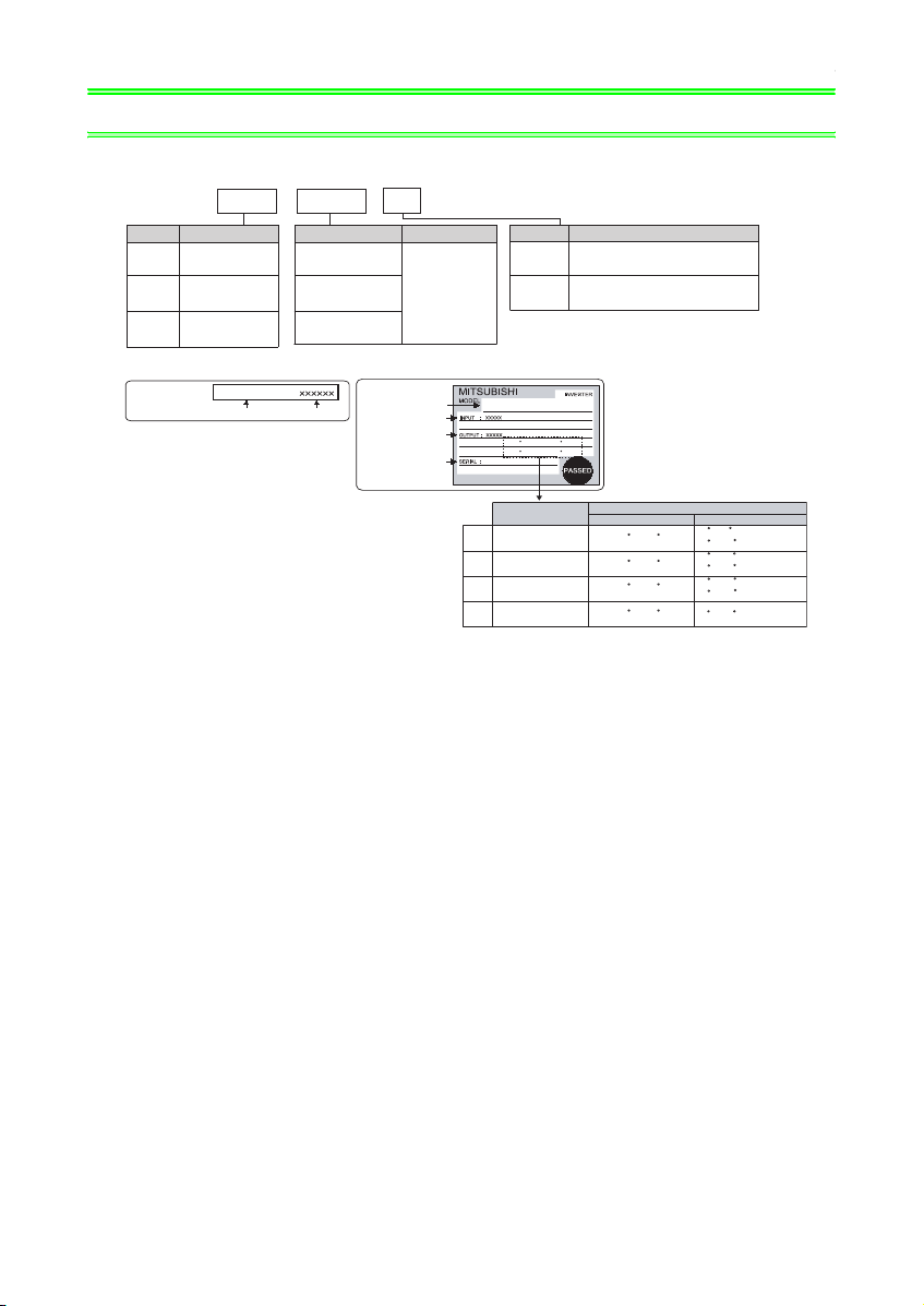
• Inverter Model
FR --A720
Symbol
Voltage Class
Three-phase
A720
200V class
Three-phase
A740
400V class
Three-phase
A760
600V class
Capacity plate
Capacity plate
Inverter model
FR-A720-00175-NA
00175 NA
Symbol
200V class
00030 to 03460
400V class
00015 to 03250
600V class
00017 to 04020
Serial number
-
Type number
Displays the
rated current
Rating plate
Rating plate
Inverter model
Input rating
Output rating
Serial number
Symbol
U.S. Specifications
NA
N4
U.S. Specifications (UL Type 1)
FR-A720-00175-NA
ND (50 C) XXA
LD (50 C) XXA
SLD (40 C) XXA
HD (50 C) XXA
Specifications
Overload current
110% 60s, 120% 3s
SLD
LD
120% 60s, 150% 3s
150% 60s, 200% 3s
ND
200% 60s, 250% 3s
HD
rating
Surrounding air temperature
FR-A720/A740 FR-A760
40 C (104 F)
50 C (122 F)
50 C (122 F)
50 C (122 F)
30 C (86 F) (00061 or less)
40 C (104 F) (00120 or more)
40 C (104 F) (00840 or less)
50 C (122 F) (01040 or more)
40 C (104 F) (00840 or less)
50 C (122 F) (01040 or more)
40 C (104 F)
1
INSTALLATION OF THE INVERTER
)
AND INSTRUCTIONS
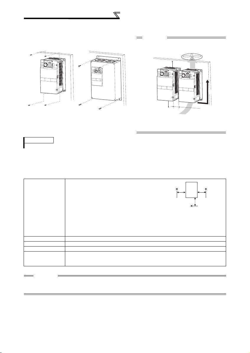
• Installation of the inverter
Note - Some inverter models may be installed ou tside an enclosure. See Appendix 2 for detai ls.
Installation on the enclosure
FR-A720-00900 or less
FR-A740-00440 or less
FR-A760-00330 or less
FR-A720-01150 or more
FR-A740-00570 or more
FR-A760-00550 or more
CAUTION
• When encasing multiple inverters, install them i n
parallel as a cooling measure.
• Install the inverter vertically.
10cm(3.94inches)
or more
*2
Vertical
Fix six positions for the FR-A740-03250 to
06830 (FR-A760-02210 to 06630) and fix
eight positions for the FR-A740-07700 to
09620.
10cm(3.94inches)
*2
or more
*1 1cm or more for FR-A720-00175
(FR-A740-00090, FR-A760-00061) or less
10cm or more for FR-A720-02880
(FR-A740-01440, FR-A760-01040) or more
*2 20cm or more for FR-A720-02880
(FR-A740-01440, FR-A760-01040) or more
5
c
m(1.97
i
nc
h
es) o
r
mor
e
*
1
REMARKS
To use an enclosed brake resistor for the FR-A760-00061 or less, refer to page 8.
• General Precaution
The bus capacitor discharge time is 10 minutes. Before starting wiring or inspection, switch power off, wait for more
than 10 minutes, and check for residual voltage between terminal P/+ and N/- with a meter etc., to avoid a hazard
of electrical shock.
• Environment
Before installation, check that the environment meets following specifications.
Surrounding air
temperature
Ambient humidity
Storage tempera ture
Ambience
Altitude, vibration
2
*1 2.9m/s
or less for the FR-A740-03250 (FR-A760-02210) or more
CAUTION
• Install the inverter on a strong surface securely and vertically with bolts.
• Leave enough clearances and take cooling measures.
• Avoid places where the inverter is subjected to direct sunlight, high temperature and high humidity.
• Install the inverter on a non-combustible wall surface.
FR-A720/A740
LD, ND (initial setting),HD:
-10°C to + 50°C (14°F to 122°F) (non-freezing)
SLD: -10°C to + 40°C (14°F to 104°F) (non-freezing)
FR-A760
LD, ND (initial setting):
-10°C to +40°C (14°F to 104°F) (non-freezing) (00840 or less)
-10°C to +50°C (14°F to 122°F) (non-freezing) (01040 or more)
HD:
-10°C to + 40°C (14°F to 104°F) (non-freezing)
SLD:
-10°C to +30°C (14°F to 86°F) (non-freezing) (00061 or less)
-10°C to +40°C (14°F to 104°F) (non-freezing) (00120 or more)
5cm
(1.97inches)
Measurement
position
Inverter
Measurement
position
5cm
(1.97inches
5cm
(1.97inches)
90%RH or less (non-condensing)
-20°C to +65°C (-4°F to 149°F)
Indoors (No corrosive and flammable gases, oil mist, dust and dirt.)
Maximum 1000m (3280.80feet) above sea level for standard operation. After that derate by 3% for
every extra 500m (1640.40feet) up to 2500m (8202feet) (91%).
5.9m/s2 or less at 10 to 55Hz (directions of X, Y, Z axes) *1
2
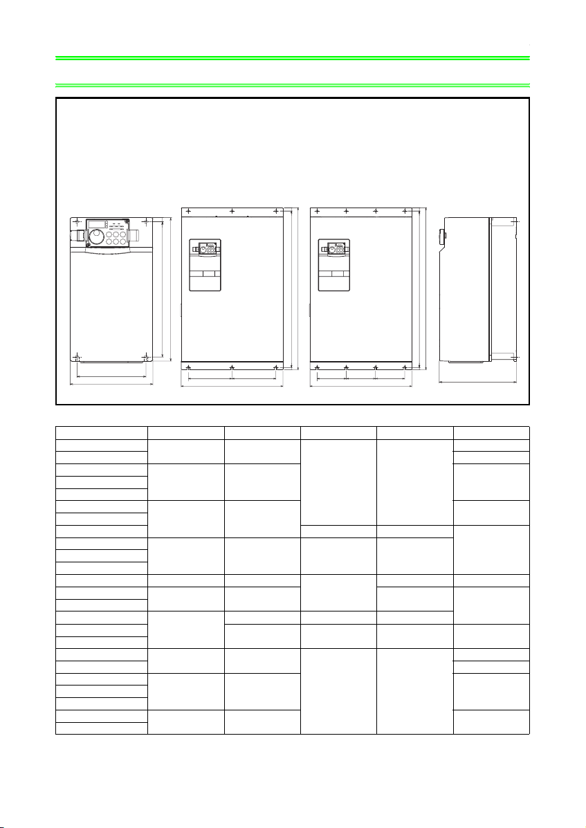
OUTLINE DIMENSION DRAWING
2 OUTLINE DIMENSION DRAWING
FR-A720-00030 to
03460-NA
FR-A740-00015 to
02600-NA
FR-A720-00030 to
00330-N4
FR-A740-00015 to
00170-N4
FR-A760-00017 to
01520-NA
FR-A740-03250 to 06830-NA
FR-A760-02020 to 04020-NA
FR-A740-07700 to 09620-NA
FR-A760-04960, 06630-NA
H
H1
W1
W
W1 W1
W
H
H1
W1 W1 W1
W
H
H1
D
(Unit:mm(inches))
• 200V class
Inverter Model W W1 H H1 D
FR-A720-00030-NA
FR-A720-00050-NA 125 (4.92)
FR-A720-00080-NA
FR-A720-00175-NA
FR-A720-00240-NA
FR-A720-00330-NA
FR-A720-00460-NA 300 (11.81) 285 (11.22)
FR-A720-00610-NA
FR-A720-00900-NA
FR-A720-01150-NA 325 (12.8) 270 (10.63)
FR-A720-01450-NA
FR-A720-01750-NA
FR-A720-02150-NA
FR-A720-02880-NA
FR-A720-03460-NA
FR-A720-00030-N4
FR-A720-00050-N4 137 (5.39)
FR-A720-00080-N4
FR-A720-00175-N4
FR-A720-00240-N4
FR-A720-00330-N4
110 (4.33) 95 (3.74)
150 (5.91) 125 (4.92) 140 (5.51)FR-A720-00110-NA
220 (8.66) 195 (7.68)
250 (9.84) 230 (9.06) 400 (15.75) 380 (14.96)FR-A720-00760-NA
435 (17.13) 380 (14.96) 525 (20.67)
260 (10.24) 245 (9.65)
530 (20.87) 195 (7.68)
550 (21.65)
410 (16.14) 700 (27.56) 675 (26.57)
465 (18.31)
110 (4.33) 95 (3.74)
150 (5.91) 125 (4.92) 152 (5.98)FR-A720-00110-N4
220 (8.66) 195 (7.68) 182 (7.17)
400 (15.75) 740 (29.13) 715 (28.15) 360 (14.17)
260 (10.24) 245 (9.65)
110 (4.33)
170 (6.69)
190 (7.48)
250 (9.84)
122 (4.80)
3
OUTLINE DIMENSION DRAWING
• 400V class
Inverter Model W W1 H H1 D
FR-A740-00015-NA
FR-A740-00025-NA
FR-A740-00040-NA
FR-A740-00060-NA
FR-A740-00090-NA
FR-A740-00120-NA
FR-A740-00170-NA
FR-A740-00230-NA
FR-A740-00310-NA
FR-A740-00380-NA
FR-A740-00440-NA
FR-A740-00570-NA 325 (12.8) 270 (10.63) 550 (21.65) 530 (20.87) 195 (7.68)
FR-A740-00710-NA
FR-A740-01100-NA
FR-A740-01440-NA
FR-A740-01800-NA
FR-A740-02160-NA
FR-A740-02600-NA
FR-A740-03250-NA
FR-A740-03610-NA
FR-A740-04320-NA
FR-A740-05470-NA
FR-A740-06100-NA
FR-A740-06830-NA
FR-A740-07700-NA
FR-A740-09620-NA
FR-A740-00015-N4
FR-A740-00025-N4
FR-A740-00040-N4
FR-A740-00060-N4
FR-A740-00090-N4
FR-A740-00120-N4
FR-A740-00170-N4
150 (5.91) 125 (4.92)
260 (10.24) 245 (9.65)
220 (8.66) 195 (7.68)
300 (11.81) 285 (11.22) 190 (7.48)
250 (9.84) 230 (9.06) 400 (15.75) 380 (14.96) 190 (7.48)
435 (17.13) 380 (14.96) 550 (21.65) 525 (20.67) 250 (9.84)FR-A740-00860-NA
620 (24.41) 595 (23.43) 300 (11.81)
465 (18.31) 400 (15.75)
740 (29.13) 715 (28.15) 360 (14.17)
498 (19.6) 200 (7.87)
1010 (39.76) 985 (38.78) 380 (14.96)
680 (26.77) 300 (11.81)FR-A740-04810-NA
790 (31.1) 315 (12.4) 1330 (52.36) 1300 (51.18)
995 (39.17) 300 (11.81) 1580 (62.2) 1550 (61.02)FR-A740-08660-NA
150 (5.91) 125 (4.92)
260 (10.24) 245 (9.65)
220 (8.66) 195 (7.68) 182 (7.17)
140 (5.51)
170 (6.69)
440 (17.32)
152 (5.98)
4
OUTLINE DIMENSION DRAWING
• 600V class
Inverter Model W W1 H H1 D
FR-A760-00017-NA
FR-A760-00061-NA
FR-A760-00120-NA
FR-A760-00220-NA 300 (11.81) 285 (11.22) 190 (7.48)
FR-A760-00330-NA 250 (9.84) 230 (9.06) 400 (15.75) 380 (14.96) 190 (7.48)
FR-A760-00550-NA
FR-A760-00840-NA
FR-A760-01040-NA
FR-A760-01520-NA
FR-A760-02210-NA
FR-A760-03040-NA 680 (26.77) 300 (11.81)
FR-A760-04020-NA 790 (31.1) 315 (12.4) 1330 (52.36) 1300 (51.18)
FR-A760-06630-NA
zWhen an enclosed brake resistor is used (FR-A760 only)
150 (5.91) 125 (4.92)
220 (8.66) 195 (7.68)
435 (17.13) 380 (14.96) 550 (21.65) 525 (20.67) 250 (9.84)
465 (18.31) 400 (15.75) 620 (24.41) 595 (23.43) 300 (11.81)FR-A760-01310-NA
498 (19.6) 200 (7.87)
995 (39.17) 300 (11.81) 1580 (62.20) 1550 (61.02)
FR-A760-00017 to 00061-NA
260 (10.24) 245 (9.65)
1010 (39.76) 985 (38.78) 380 (14.96)FR-A760-02550-NA
140 (5.51)FR-A760-00040-NA
170 (6.69)
440 (17.32)FR-A760-04960-NA
195 (7.68)
220 (8.66)
260 (10.23)
245 0.3 (9.64 0.01)
160 (6.29)
(Unit:mm(inches))
5
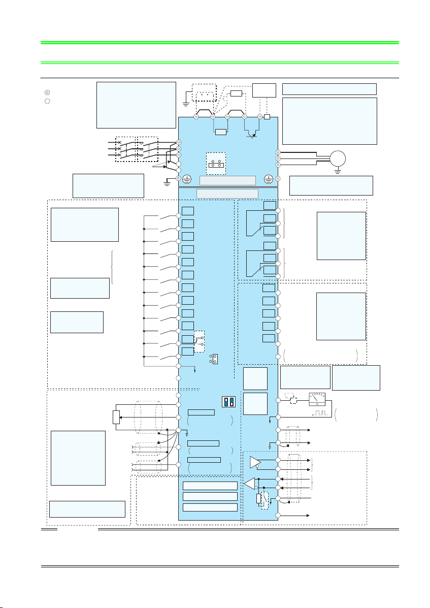
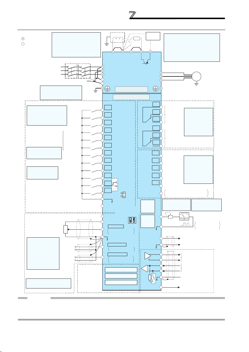
Terminal connection diagram (FR-A720/740)
3WIRING
3.1 Terminal connection diagram (FR-A720/740)
Sink logic
*1. DC reactor (FR-HEL)
Main circuit terminal
Control circuit terminal
Three-phase AC
Control input signals (No voltage input allowed)
Terminal functions vary with
the input terminal
assignment (Pr. 178 to Pr. 189)
(Refer to the Instruction
Manual)
*3. JOG terminal can be used
as pulse train input terminal.
Use Pr. 291 to select
JOG/pulse.
Be sure to connect the DC reactor
supplied with the FR-A720-02880 (FRA740-01440) or more.
When using the FR-A720-02150 (FRA740-01100) with LD or SLD set,
always use a DC reactor (option).
When a DC reactor is connected to the
FR-A720-02150 (FR-A740-01100) or
less, remove the jumper across P1-P/+.
MCCB
power supply
*2. To supply power to the
control circuit separately,
remove the jumper across
R1/L11 and S1/L21.
Forward
rotation
Reverse
rotation
Start self-
holding selection
Multi-speed
selection
High speed
Middle
speed
Low speed
Jog mode
Jumper
start
start
MC
*2
Earth
(Ground)
Second function selection
*4. AU terminal can be
used as PTC input
terminal.
Terminal 4 input selection
Selection of automatic restart
(Common for external power supply transistor)
Output stop
Reset
(Current input selection)
after instantaneous
power failure
Contact input common
24VDC power supply
Frequency setting signal (Analog)
1/2W1k
*6
3
Ω
1
Auxiliary
input
Terminal
4 input
(Current
input)
2
(+)
(-)
(+)
(-)
Connector
for plug-in option
connection
Frequency setting
potentiometer
*
Terminal input specifications
5.
can be changed by analog
input specifications
switchover (Pr. 73, Pr. 267).
Set the voltage/current input
switch in the OFF position to
select voltage input (0 to 5V/0
to10V) and ON to select
current input (4 to 20mA).
(Refer to the Instruction
Manual)
*6
. It is recommended to use 2W1kΩ
when the frequency setting signal
is changed frequently.
CAUTION
· To prevent a malfunction due to noise, keep the signal cables more than 10cm (3.94inches) away from the power cables. Also separate the main
circuit wire of the input side and the output side.
· After wiring, wire offcuts must not be left in the inverter.
Wire offcuts can cause an alarm, failure or malfunction. Always keep the inverter clean.
When drilling mounting holes in an enclosure etc., take care not to allow chips and other foreign matter to enter the inverter.
· Set the voltage/current input switch correctly. Different setting may cause a fault, failure or malfunction.
*1
Jumper
Earth
(Ground)
P1
R/L1
S/L2
T/L3
R1/L11
S1/L21
Main circuit
Control circuit
STF
STR
STOP
RH
RM
RL
JOG
*3
RT
MRS
RES
*4
AU
AU
PTC
CS
SD
PC
*5
10E(+10V)
10(+5V)
0 to 5VDC
2
0 to 10VDC
0 to 20mADC
5
(Analog common)
±
10VDC
0 to
1
0 to ±5VDC
4 to 20mADC
4
0 to 5VDC
0 to 10VDC
Option connector 1
Option connector 2
Option connector 3
R
*8
Jumper
Jumper
PX PR N/-P/+
R
ON
EMC filter
ON/OFF
connecter
OFF
SINK
SOURCE
Voltage/current
input switch
2
4
ON
OFF
(Initial value)
selected
*5
(Initial value)
selected
*5
(Initial value)
*5
selected
*9
PU
connector
USB
connector
Terminating
resistor
*7. A CN8 connector (for MT-BU5) is provided with
Brake unit
(Option)
the FR-A720-02880 (FR-A740-01440) or more.
*8. Brake resistor (FR-ABR)
Remove the jumper across terminal PR-PX
when connecting a brake resistor.
(FR-A720-00030 to 00330 (FR-A740-00015 to 00170))
CN8
Terminal PR is provided for the
*7
to 00900 (FR-A740-00015 to 00440)
Install a thermal relay to prevent an overheat
and burnout of the brake resistor.
(Refer to the Instruction Manual)
U
V
W
*9.The FR-A720-00030 and 00050
are not provided with the EMC
filter ON/OFF connector. (Always on)
C1
B1
Relay output 1
(Fault output)
A1
C2
B2
Relay output 2
A2
RUN
Running
SU
Up to frequency
IPF
Instantaneous
power failure
OL
Overload
FU
Frequency detection
SE
Open collector output common
Sink
/source common
*
10. It is not necessary
when calibrating the
indicator from the
operation panel.
+
FM
*11
Calibration
resistor *10
SD
AM
5
(+)
(-)
TXD+
TXD-
RXD+
RXD-
SG
VCC
5V
FR-A720-00030
.
Motor
IM
Earth (Ground)
Relay output
Terminal functions
vary with the output
terminal assignment
(Pr. 195, Pr. 196)
(Refer to the
Instruction Manual)
Open collector output
Terminal functions
vary with the output
terminal assignment
(Pr. 190 to Pr. 194)
(Refer to t he
Instruction Manual)
*11. FM terminal can
be used for pulse
train output of open
collector output
using Pr. 291.
-
Indicator
(Frequency meter, etc.)
Moving-coil type
1mA full-scale
Analog signal output
(0 to 10VDC)
RS-485 terminals
Data transmission
Data reception
GND
(Permissible load
current 100mA)
6
WIRING
3.2 Terminal connection diagram (FR-A760)
Sink logic
Main circuit terminal
Control circuit terminal
Control input signals (No voltage input allowed)
Terminal functions vary with
the input terminal
assignment (Pr. 178 to Pr. 189)
(Refer to the Instruction
Manual)
*3. JOG terminal can be used
as pulse train input terminal.
Use Pr. 291 to select
JOG/pulse.
*4. AU terminal can be
used as PTC input
terminal.
(Common for external power supply transistor)
Frequency setting signal (Analog)
*
Terminal input specifications
5.
can be changed by analog
input specifications
switchover (Pr. 73, Pr. 267).
Set the voltage/current input
switch in the OFF position to
select voltage input (0 to 5V/0
to10V) and ON to select
current input (4 to 20mA).
(Refer to the Instruction
Manual)
*6
. It is recommended to use 2W1kΩ
when the frequency setting signal
is changed frequently.
CAUTION
· To prevent a malfunction due to noise, keep the signal cables more than 10cm (3.94inches) away from the power cables. Also separate the main
circuit wire of the input side and the output side.
· After wiring, wire offcuts must not be left in the inverter.
Wire offcuts can cause an alarm, failure or malfunction. Always keep the inverter clean.
When drilling mounting holes in an enclosure etc., take care not to allow chips and other foreign matter to enter the inverter.
· Set the voltage/current input switch correctly. Different setting may cause a fault, failure or malfunction.
*1. DC reactor
Be sure to connect the DC reactor
supplied with the FR-A760-01040 or more.
When using the FR-A760-00840 with LD
or SLD set, always use a DC reactor
(option).
When a DC reactor is connected to the
FR-A760-00840 or less, remove the
jumper across P1-P/+.
MCCB
Three-phase AC
power supply
*2. To supply power to the
control circuit separately,
remove the jumper across
R1/L11 and S1/L21.
Forward
rotation
Reverse
rotation
Start self-
holding selection
Multi-speed
selection
High speed
Low speed
Jog mode
Second function selection
Output stop
Terminal 4 input selection
(Current input selection)
Selection of automatic restart
after instantaneous
power failure
Contact input common
24VDC power supply
1/2W1k
*6
3
Ω
1
Auxiliary
input
Terminal
4 input
(Current
input)
2
Frequency setting
potentiometer
Jumper
start
start
Middle
speed
Reset
(+)
(-)
(+)
(-)
Connector
for plug-in option
connection
MC
*2
Earth
(Ground)
*1
Jumper
Earth
(Ground)
P1
R/L1
S/L2
T/L3
R1/L11
S1/L21
Main circuit
Control circuit
STF
STR
STOP
RH
RM
RL
JOG
*3
RT
MRS
RES
*4
AU
AU
PTC
CS
SD
SOURCE
PC
*5
Voltage/current
10E(+10V)
10(+5V)
0 to 5VDC
2
0 to 10VDC
0 to 20mADC
5
(Analog common)
±
10VDC
0 to
1
0 to ±5VDC
4 to 20mADC
4
0 to 5VDC
0 to 10VDC
Option connector 1
Option connector 2
Option connector 3
Jumper
SINK
input switch
4
ON
OFF
(Initial value)
selected
(Initial value)
selected
(Initial value)
selected
R
*7
PX PR N/-P/+
2
*5
*5
*5
Brake unit
(Option)
C1
B1
A1
C2
B2
A2
RUN
SU
IPF
OL
FU
PU
connector
USB
connector
TXD+
TXD-
RXD+
RXD-
Terminating
VCC
resistor
*7. Brake resistor (Accessories)
The brake resistor is provided with the FRA760-00017 to 00061. Connect the accessory
brake resistor to P/+-PR.
Terminal PR is provided for the
.
to 00330
Install a thermal relay to prevent an overheat
and burnout of the brake resistor.
(Refer to the Instruction Manual)
U
V
W
Relay output 1
(Alarm output)
Terminal functions
vary with the output
terminal assignment
(Pr. 195, Pr. 196)
(Refer to the
Instruction Manual)
Relay output 2
Running
Up to frequency
Instantaneous
power failure
Overload
Frequency detection
SE
*
8. It is not necessary
FM
*9
Calibration
resistor *8
SD
AM
5
Open collector output
Terminal functions
vary with the output
terminal assignment
(Pr. 190 to Pr. 194)
(Refer to the
Instruction Manual)
Open collector output common
Sink
/source common
when calibrating the
indicator from the
operation panel.
+
(+)
(-)
RS-485 terminals
Data transmission
Data reception
SG
GND
(Permissible load
5V
current 100mA)
FR-A760-00017
Motor
IM
Earth (Ground)
Relay output
*9. FM terminal can be
used for pulse train
output of open collector
output using Pr. 291.
-
Indicator
(Frequency meter, etc.)
Moving-coil type
1mA full-scale
Analog signal output
(0 to 10VDC)
7
WIRING
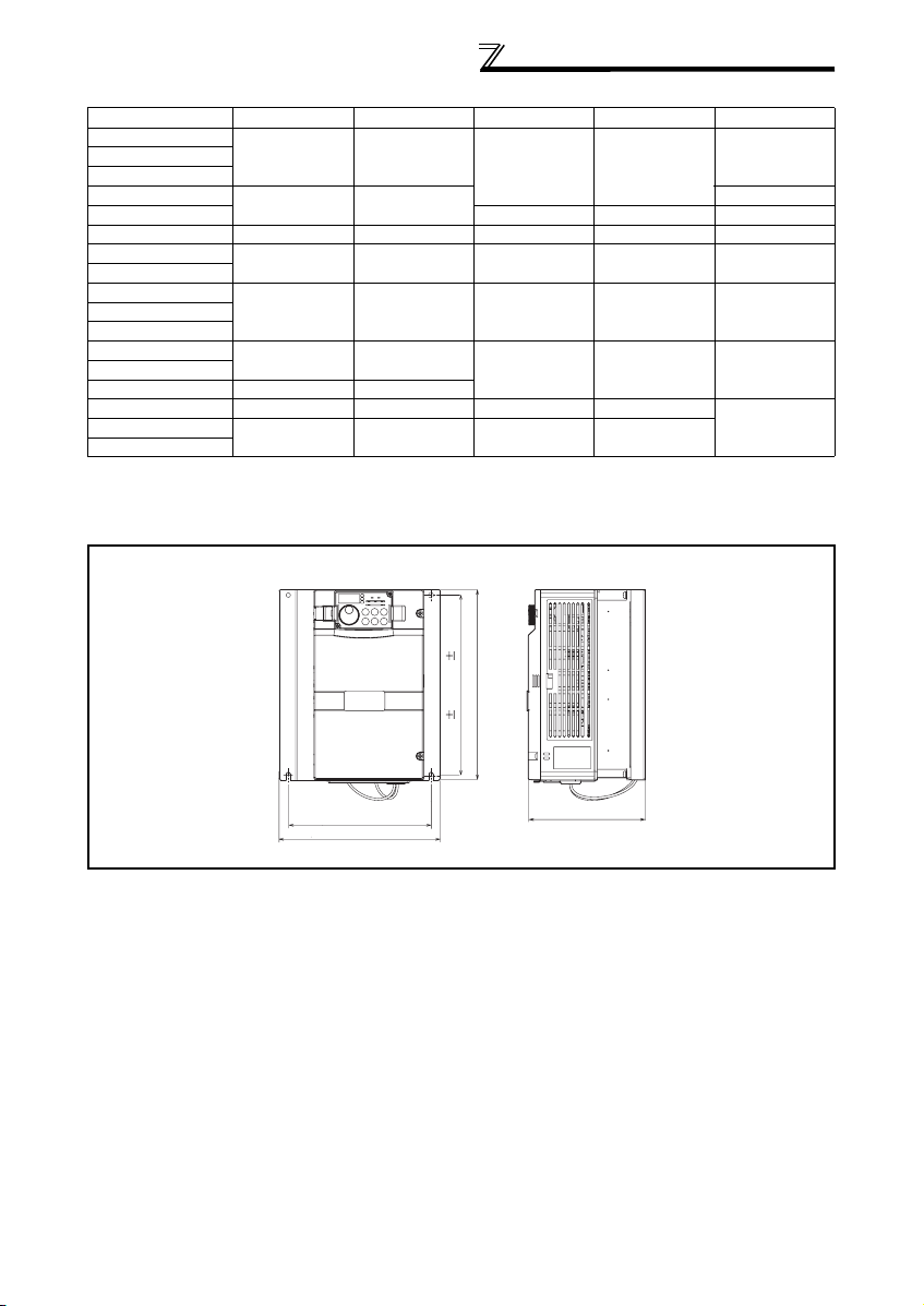
3.3 Connection of provided brake resistor (FR-A760 only)
Connecting the brake resistor enclosed with the unit to the FR-A760-00017 to 00061 will improve regeneration
capability.
(1) Installation procedure
Connect the brake resistor to the inverter with provided screws.
REMARKS
Connecting the brake resistor changes the protective structure to OPEN type (NEMA1).
(2) Connection
Wiring cover and Handling (FR-A760-00061 or less)
1) Remove the wiring cover of the inverter. Punch out a knockout by firmly tapping it with such as a hammer. Remove
any sharp edges and burrs from knockout holes of the wiring cover.
Wiring cover
8
WIRING
2)Attach protective bushes provided to the wiring cover and cut with nippers or a cutter before running the cables.
Connect the wire with red sleeve to PR terminal. Connect the wire with transparent sleeve to P/+.
Protective bushes
(Accessory)
(Red sleeve)
To PR terminal.
(Transparent sleeve)
To P/+ terminal.
(3) Installation of the inverter
CAUTION
When handling the wiring cover, care must be taken not to cut fingers or hands with sharp edges and burrs.
Avoid wire offcuts and other foreign matter from entering the inverter.
WARNING
Do not wire without using protective bushes. Otherwise, the cable sheathes may be scratched by the wiring
cover edges, resulting in a short circuit or ground fault.
9
WIRING
r
3.4 Main circuit terminal
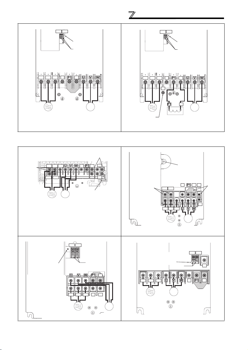
(1) Terminal layout and wiring
200V class
FR-A720-00030, 00050-NA/N4 FR-A720-00080, 00110, 00175-NA/N4
Screw size (M4)
R/L1
T/L3
Jumper
S/L2
Jumper
PR
Jumper
Screw size (M4)
R/L1 S/L2 T/L3
Jumper
PR
P/+
N/-
N/-
R1/L11
S1/L21
IM
Power supply
FR-A720-00240, 00330-NA/N4
Jumper
Screw size
Motor
As this is an inside cover fixing screw,
do not remove it.
*
R1/L11 S1/L21
(M5)
R/L1 S/L2 T/L3
P/+
*
Screw size
(M4)
Charge lamp
N/-
PX
P/+
Charge lamp
*
PR
PX
*
FR-A720-00460-NA
Jumpe
R1/L11 S1/L21
Power
supply
Charge lamp
Screw size (M5)
IM
Motor
R/L1 S/L2 T/L3
IM
Power supply
* Screw size of terminal R1/L11, S1/L21, PR, and PX is M4.
FR-A720-00610, 00760, 00900-NA FR-A720-01150, 01450, 01750-NA
Screw size
(00610:M6, 00760, 00900:M8)
Charge lamp
R/L1 S/L2 T/L3
Power supply
Motor
Screw size (M5)
Screw size (M4)
Jumper
IM
Motor
R1/L11 S1/L21
N/-
Jumper
P/+
R1/L11 S1/L21
Screw size
(M4)
PR
Screw size
(01150:M8, 01450, 01750:M10)
Screw size
(M4)
R1/L11 S1/L21
Screw size
Power supply
Screw size (M5)
Charge lamp
Jumper
(M4)
Jumper
PX
Charge lamp
Jumper
P/+
N/-
PR
IM
Motor
10
Screw size (M6)
N/-
R/L1 S/L2 T/L3
Power
supply
01450/01750:M8)
Jumper
Screw size
(01150:M6,
P/+
IM
Motor
WIRING
r
FR-A720-02150-NA
R1/L11 S1/L21
Screw size (M4)
Charge lamp
Jumper
Screw size (M12)
R/L1 S/L2 T/L3
Power supply
* When using the inverter with LD or SLD set, remove a jumper
between P/+ and P1 and connect a DC reactor (FR-HEL-75K
option).
N/-
P/+
Jumper *
Screw size (M8)
IM
Motor
FR-A720-02880, 03460-NA
R1/L11 S1/L21
R/L1 S/L2 T/L3
Power supply
Screw size (M12)
(for option)
P/+
400V class
FR-A740-00015 to 00090-NA/N4 FR-A740-00120, 00170-NA/N4
(M4)
Jumper
PR
P/+
N/-
PX
Charge lamp
Jumper
Screw size
R1/L11 S1/L21
(M4)
R/L1 S/L2 T/L3
Jumper
Screw size (M4)
R/L1 S/L2 T/L3
R1/L11 S1/L21
Power
supply
IM
Motor
Screw size
Screw size (M4)
N/-
Screw size
(M10)
DC reactor
Charge lamp
Jumper
Screw size (M12)
P/+
P/+
IM
Motor
Charge lamp
N/-
P/+
PR
Jumpe
PX
Power supply
FR-A740-00230, 00310-NA FR-A740-00380, 00440-NA
R1/L11 S1/L21
Screw size
(M4)
Charge lamp
Screw size (M5)
R/L1 S/L2 T/L3
Power supply
Screw size (M5)
Jumper
Jumper
N/-
Screw size (M6)
P/+
PR
IM
Motor
Charge lamp
R/L1 S/L2 T/L3
Power supply
Screw size (M6)
IM
Motor
Screw size
(M4)
Screw size (M4)
Jumper
IM
Motor
R1/L11 S1/L21
N/-
Jumper
PR
P/+
11
 Loading...