

Mitsubishi FR-A720-02880-NA, FR-A720-55K, FR-A740-55K, FR-A740-01100-NA, FR-A740-01800-EC Instruction Manual
...
INVERTER
Plug-in option
PRE-OPERATION INSTRUCTIONS
1
FR-A7NS
INSTRUCTION MANUAL
SSCNET III communication function
INSTALLATION
WIRING
SSCNET III COMMUNICATION
STATUS
INVERTER SETTING AND
DISPLAY
RESTRICTIONS ON THE
FUNCTIONS
PRECAUTIONS
ALARM INDICATION DEFINITIONS
AND CORRECTIVE ACTIONS
TROUBLESHOOTING
2
3
4
5
6
7
8
9
Thank you for choosing this Mitsubishi Inverter plug-in option.
This instruction manual gives handling information and
precautions for use of this equipment. Incorrect handling might
cause an unexpected fault. Before using the equipment, please
read this manual carefully to use the equipment to its optimum.
Please forward this manual to the end user.
This section is specifically about
safety matters
Do not attempt to install, operate, maintain or inspect this
product until you have read through this instruction manual and
appended documents carefully and can use the equipment
correctly. Do not use this product until you have a full
knowledge of the equipment, safety information and
instructions.
In this instruction manual, the safety instruction levels are
classified into "WARNING" and "CAUTION".
Assumes that incorrect handling may
WARNING
CAUTION
Note that even the level may lead to a serious
consequence according to conditions. Please follow the
instructions of both levels because they are important to
personnel safety.
cause hazardous conditions, resulting
in death or severe injury.
Assumes that incorrect handling may
cause hazardous conditions, resulting
in medium or slight injury, or may
cause physical damage only.
CAUTION
SAFETY INSTRUCTIONS
1. Electric Shock Prevention
WARNING
• While power is on or when the inverter is running, do not
open the front cover. You may get an electric shock.
• Do not run the inverter with the front cover or wiring cover
removed. Otherwise, you may access the exposed highvoltage terminals and charging part and get an electric shock.
• If power is off, do not remove the front cover except for wiring
or periodic inspection. You may access the charged inverter
circuits and get an electric shock.
• Before starting wiring or inspection, check to make sure that
the indication of the inverter operation panel is off, wait for at
least 10 minutes after the power supply has been switched off,
and check that there are no residual voltage using a tester or
the like. The capacitor is charged with high voltage for some
time after power off and it is dangerous.
• Any person who is involved in the wiring or inspection of this
equipment should be fully competent to do the work.
• Always install the plug-in option before wiring. Otherwise,
you may get an electric shock or be injured.
• Do not touch the plug-in option with wet hands. Otherwise
you may get an electric shock.
• Do not subject the cables to scratches, excessive stress,
heavy loads or pinching. Otherwise you may get an electric
shock.
A-1

2. Injury Prevention
3) Usage
CAUTION
• Apply only the voltage specified in the instruction manual to
each terminal. Otherwise, burst, damage, etc. may occur.
• Ensure that the cables are connected to the correct terminals.
Otherwise, burst, damage, etc. may occur.
• Always make sure that polarity is correct to prevent damage, etc.
Otherwise, burst, damage may occur.
• While power is on or for some time after power-off, do not touch
the inverter as it is hot and you may get burnt.
3. Additional Instructions
Also note the following points to prevent an accidental failure,
injury, electric shock, etc.
1) Transportation and mounting
CAUTION
• Do not install or operate the plug-in option if it is damaged or
has parts missing.
• Do not stand or rest heavy objects on the product.
• Check that the mounting orientation is correct.
• Prevent other conductive bodies such as screws and metal
fragments or other flammable substance such as oil from
entering the inverter.
2) Trial run
CAUTION
• Before starting operation, confirm and adjust the parameters.
A failure to do so may cause some machines to make
unexpected motions.
WARNING
• Do not modify the equipment.
• Do not perform parts removal which is not instructed in this
manual. Doing so may lead to fault or damage of the inverter.
CAUTION
• When parameter clear or all parameter clear is performed,
reset the required parameters before starting operations.
Each parameter returns to the initial value.
• For prevention of damage due to static electricity, touch
nearby metal before touching this product to eliminate static
electricity from your body.
4) Maintenance, inspection and parts replacement
CAUTION
• Do not test the equipment with a megger (measure insulation
resistance).
5) Disposal
CAUTION
• Treat as industrial waste.
6) General instruction
All illustrations given in this manual may have been drawn with
covers or safety guards removed to provide in-depth
description. Before starting operation of the product, always
return the covers and guards into original positions as specified
and operate the equipment in accordance with the manual.
A-2

CONTENTS
1 PRE-OPERATION INSTRUCTIONS 1
1.1 Inverter Type ......................................................................................................................................1
1.2 Unpacking and Product Confirmation .............................................................................................2
1.2.1 Packing confirmation ......................................................................................................................................7
1.2.2 Parts ...............................................................................................................................................................8
1.3 Caution................................................................................................................................................9
1.4 Operation Overview .........................................................................................................................10
2 INSTALLATION 12
2.1 Pre-Installation Instructions ...........................................................................................................12
2.2 Shaft number Setting.......................................................................................................................13
2.3 Installation Procedure .....................................................................................................................14
3 WIRING 16
3.1 System configuration (when FR-A7AP is used)............................................................................16
3.2 Wiring example (when FR-A7AP is used)......................................................................................18
3.3 SSCNET III cable ..............................................................................................................................20
3.3.1 SSCNET III cable laying...............................................................................................................................24
3.4 Wiring................................................................................................................................................26
4 SSCNET III COMMUNICATION STATUS 32
I

5 INVERTER SETTING AND DISPLAY 35
5.1 Parameter List ..................................................................................................................................35
5.2 Operation Mode Setting ..................................................................................................................36
5.2.1 Operation mode indication............................................................................................................................36
5.2.2 Operation mode switchover method.............................................................................................................37
5.3 Operation at Communication Error Occurrence...........................................................................40
5.3.1 Alarm and measures ....................................................................................................................................40
5.4 Inverter Reset ...................................................................................................................................41
5.5 Setting SSCNET III communication function ................................................................................42
5.5.1 Pr.499 SSCNET III operation selection........................................................................................................42
5.5.2 Pr.379 SSCNET III rotation direction selection.............................................................................................47
5.5.3 Pr.449 SSCNET III input filter setting ...........................................................................................................48
5.5.4 Pr.52 DU/PU main display data selection.....................................................................................................48
5.5.5 Pr.185 JOG terminal function selection........................................................................................................49
5.5.6 Pr.800 Control method selection..................................................................................................................49
6 RESTRICTIONS ON THE FUNCTIONS 50
6.1 Function Restriction List.................................................................................................................50
6.2 Inverter Parameter List ....................................................................................................................53
6.3 Inverter I/O Terminal Function List ................................................................................................69
6.3.1 Input terminal function..................................................................................................................................69
6.3.2 Output terminal function ...............................................................................................................................72
II

7 PRECAUTIONS 74
8 ALARM INDICATION DEFINITIONS AND CORRECTIVE ACTIONS 75
9 TROUBLESHOOTING 79
III
1 PRE-OPERATION INSTRUCTIONS
1.1 Inverter Type
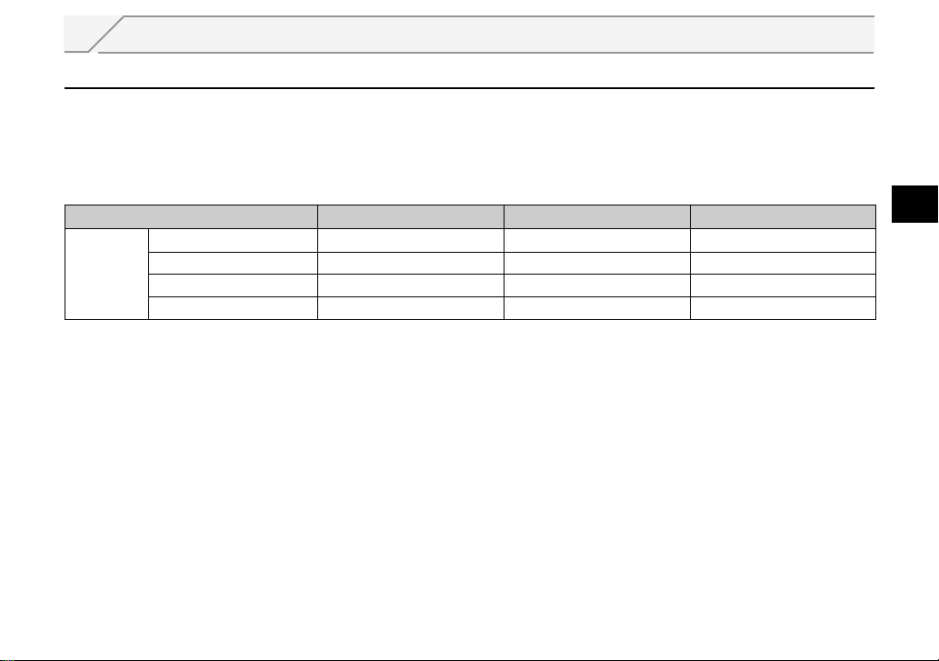
The inverter type, 55K and 75K stated in this Instruction Manual differs according to each -NA, -EC, -CH(T)
versions. Refer to the following correspondence table for each inverter type. (Refer to the instruction manual
of each inverter for the inverter type.)
For example, "for the 75K or more" indicates "for the FR-A740-01440-NA or more" in the case of FR-A740
of NA version.
NA EC CH
FR-A720-55K FR-A720-02150-NA
A700
FR-A720-75K FR-A720-02880-NA
FR-A740-55K FR-A740-01100-NA FR-A740-01800-EC FR-A740-55K-CHT
FR-A740-75K FR-A740-01440-NA FR-A740-02160-EC FR-A740-75K-CHT
1
1
PRE-OPERATION INSTRUCTIONS
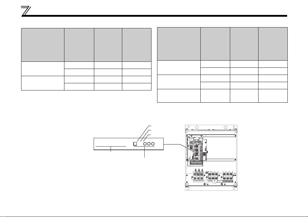
1.2 Unpacking and Product Confirmation
Take the plug-in option out of the package, check the unit name, and confirm that the product is as you
ordered and intact.
This product is a plug-in option for the FR-A700 series inverter assembled in and after January 2007.
Refer to the table below to check the SERIAL (Serial No.) indicated on the inverter rating plate or package.
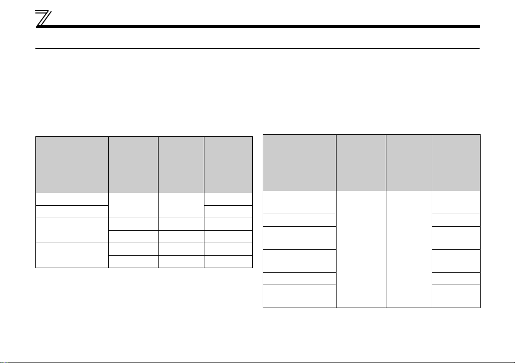
(1) NA specification
z200V class
Label on
Inverter Type
FR-A720-00030-NA
FR-A720-00050-NA P71
FR-A720-00080/
00110-NA
FR-A720-00175-NA
Product
Package
Identification
Symbol
Without G5
Without G5 Q71
<G> G7 D71
Without G5 R71
<G> G7 D71
Lower Third
and Second
Number of
TC Number
on Rating
Plate
SERIAL
(Upper
Three
Numbers of
SERIAL)
Q71
Label on
Inverter Type
FR-A720-00240/
00330-NA
FR-A720-00460-NA P71
FR-A720-00610 to
00900-NA
FR-A720-01150 to
01750-NA
FR-A720-02150-NA P71
FR-A720-02880/
03460-NA
Product
Package
Identification
Symbol
Without G5
Lower Third
and Second
Number of
TC Number
on Rating
Plate
SERIAL
(Upper
Three
Numbers of
SERIAL)
Q71
R71
Q71
M71
2
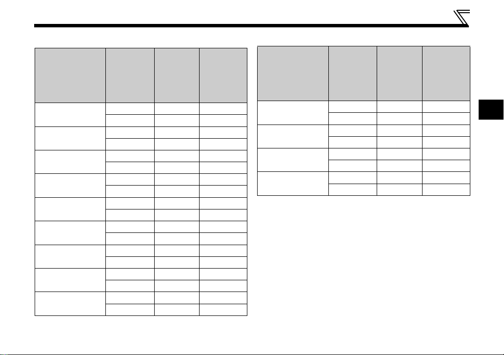
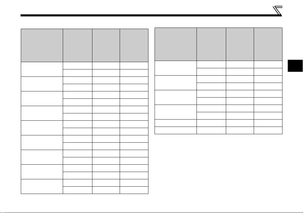
z400V class
Inverter Type
FR-A740-00015 to
00310-NA
FR-A740-00380/
00440-NA
FR-A740-00570 to
00860-NA
FR-A740-01100-NA
FR-A740-01440
to 02660-NA
FR-A740-03250-NA
FR-A740-03610-NA
FR-A740-04320/
04810-NA
FR-A740-05470-NA
Label on
Product
Package
Identification
Symbol
Without G5 Q71
<G> G7 E71
Without G5 Q71
<G> G7 F71
Without G5 P71
<G> G7 E71
Without G5 P71
<G> G7 D71
Without G5 M71
<G> G7 E71
Without G5 N71
<G> G7 F71
Without G5 M71
<G> G7 F71
Without G5 M71
<G> G7 E71
Without G5 N71
<G> G7 E71
Lower Third
and Second
Number of
TC Number
on Rating
Plate
Numbers of
SERIAL
(Upper
Three
SERIAL)
PRE-OPERATION INSTRUCTIONS
Inverter Type
FR-A740-06100-NA
FR-A740-06830-NA
FR-A740-07700/
08600-NA
FR-A740-09620-NA
Label on
Product
Package
Identification
Symbol
Without G5 M71
<G> G7 D71
Without G5 J71
<G> G7 D71
Without G5 M71
<G> G7 D71
Without G5 N71
<G> G7 D71
Lower Third
and Second
Number of
TC Number
on Rating
Plate
Numbers of
SERIAL
(Upper
Three
SERIAL)
1
3
PRE-OPERATION INSTRUCTIONS
(2) EC specification
Label on
Product
Inverter Type
Package
Identification
Symbol
FR-A740-00023 to
00126-EC
FR-A740-00170/
00250-EC
* For the FR-A740-00770 to 12120-EC
Check the SERIAL indicated on the Serial number sticker shown below.
Without G5 or G6 M71
<G> G7 or G8 F71
Without G5 or G6 N71
<G> G7 or G8 F71
Serial number sticker example
The SERIAL consists of 1 version symbol, 2 numeric characters
or 1 numeric character and 1 alphabet letter indicating year and
month, and 3 numeric characters indicating control number.
Month is indicated as 1 to 9, X (October), Y (November), and Z
(December).
To check the SERIAL, the front cover must be removed.
For the removal of the front cover, refer to the inverter manual.
Lower Third
and Second
Number of
TC Number
on Rating
Plate
FR-CA70-EC 71
SERIAL
(Upper
Three
Numbers of
SERIAL)
SERIAL
Control unit type
SERIAL (Serial No.)
Symbol
Yea r
Month
Inverter Type
FR-A740-00310/
00380-EC
FR-A740-00470/
00620-EC
FR-A740-00770 to
12120-EC*
Label on
Product
Package
Identification
Symbol
Lower Third
and Second
Number of
TC Number
on Rating
Plate
Numbers of
Without G5 or G6 M71
<G> G7 or G8 F71
Without G5 N71
<G> G7 G71
VUW
SERIAL
(Upper
Three
SERIAL)
L71 or F71
4
(3) CHT specification
Label on
Inverter Type
FR-A740-0.4K/
0.75K-CHT
FR-A740-1.5K to
15K-CHT
FR-A740-18.5K/
22K-CHT
FR-A740-30K to
45K-CHT
FR-A740-55K-CHT
FR-A740-75K to
132K-CHT
FR-A740-160K-CHT
FR-A740-185K-CHT
FR-A740-220K/
250K-CHT
Product
Package
Identification
Symbol
Without G5 or G6 S71
<G> G7 or G8 E71
Without G5 or G6 T71
<G> G7 or G8 E71
Without G5 or G6 U71
<G> G7 or G8 F71
Without G5 or G6 Q71
<G> G7 or G8 E71
Without G5 or G6 Q71
<G> G7 or G8 D71
Without G5 M71
<G> G7 E71
Without G5 N71
<G> G7 F71
Without G5 M71
<G> G7 F71
Without G5 M71
<G> G7 E71
Lower Third
and Second
Number of
TC Number
on Rating
Plate
SERIAL
(Upper
Three
Numbers of
SERIAL)
PRE-OPERATION INSTRUCTIONS
Inverter Type
FR-A740-280K-CHT
FR-A740-315K-CHT
FR-A740-355K-CHT
FR-A740-400K-CHT
FR-A740-450K-CHT
FR-A740-500K-CHT
Label on
Product
Package
Identification
Symbol
Without G5 N71
<G> G7 E71
Without G5 M71
<G> G7 D71
Without G5 K71
<G> G7 D71
Without G5 M71
<G> G7 D71
Without G5 M71
Without G5 N71
Lower Third
and Second
Number of
TC Number
on Rating
Plate
Numbers of
SERIAL
(Upper
Three
SERIAL)
1
5
PRE-OPERATION INSTRUCTIONS
z SERIAL number check
Refer to the inverter manual for the location of the rating plate.
Rating plate example
Symbol Year Month Control number
The SERIAL consists of 1 version symbol, 2 numeric characters or 1 numeric character
and 1 alphabet letter indicating year and month, and 6 numeric characters indicating
control number.
Month is indicated as 1 to 9, X (October), Y (November), and Z (December).
7 1 {{{{{{
SERIAL (Serial No.)
TC{{{A{{{G{{ TC number
Label on the product package
Inverter Type
Identification Symbol
71
Bar code
SERIAL (Serial No.)
The SERIAL (Serial No.) indicated on the
label of the product package consists of
six digits including the first three digits of
the control number and a symbol.
Input rating
6
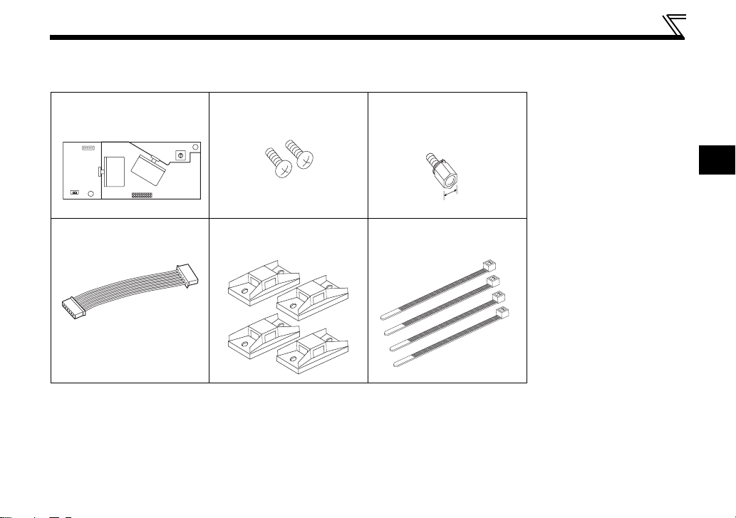
1.2.1 Packing confirmation
Check the enclosed items.
Plug-in option
......................................... 1
Mounting screw (M3 × 6mm)
............ 2 (Refer to page 13.)
0
1
F
2
E
3
D
4
C
5
B
6
A
7
9
8
PRE-OPERATION INSTRUCTIONS
Hex-head screw for option
mounting (5.5mm)
............. 1 (Refer to page 13.)
1
5.5mm
FR-A7AP connection cable
............ 1 (Refer to page 14.)
Cable clamp
............ 4 (Refer to page 31.)
Cable tie
............ 4 (Refer to page 31.)
Microsoft and Windows are registered trademark or trademark of Microsoft Corporation in the United States and/or
other countries.
®
The formal name of Windows
The formal name of Windows
2000 is Microsoft® Windows® 2000 operating system.
®
XP is Microsoft® Windows® XP operating system.
Company and product names herein are the trademarks or registered trademarks of their respective owners.
7
PRE-OPERATION INSTRUCTIONS
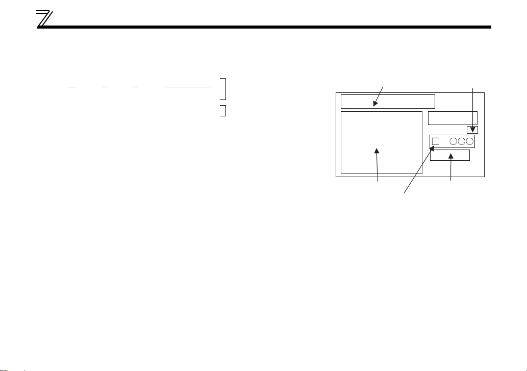
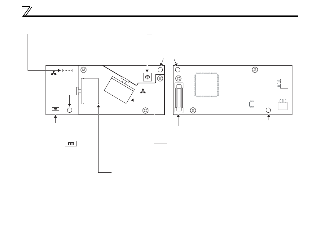
1.2.2 Parts
FR-A7AP connector
Use this connector to connect to the FR-A7AP/
FR-A7AL. Connecting to the FR-A7AP/FR-A7AL
enables the inverter to receive encoder feedback
data.
(Refer to page 14.)
Front view Rear view
FR-A7NS_B
Shaft number switch
Set the shaft number.
(Refer to page 12.)
Mounting
hole
0
1
2
F
3
E
4
D
5
C
6
B
7
A
9
8
Mounting
hole
1
2
O
N
SW1
Switch for manufacturer
setting
Do not change from initially-
1
set status (1: ).
8
O
N
FR-A7NS
2
FR-A7NS_T
Connector
Connect to the inverter option connector.
SSCNET III cable connector (CN1A)
Connect the servo system controller, the preceding
axis inverter or the servo amplifier.
SSCNET III cable connector (CN1B)
(Refer to page 26.)
Connect the following axis inverter or the servo amplifier.
For the final axis, puts a cap.
Mounting hole
(Refer to page 26.)

PRE-OPERATION INSTRUCTIONS
1.3 Caution
(1) Refer to the following manuals or software HELP for full information on the servo system controller.
y Q173DCPU/Q172DCPU user's manual ................................................... IB-0300133
y Q173DCPU/Q172DCPU motion controller (SV13/SV22)
programming manual (real mode version)................................................ IB-0300136
y Q173DCPU/Q172DCPU motion controller
programming manual (common mode version)........................................ IB-0300134
y Q173DCPU/Q172DCPU motion controller (SV13/SV22)
programming manual (Motion SFC version)............................................. IB-0300135
y Q173DCPU/Q172DCPU motion controller (SV22)
programming manual (virtual mode version)............................................ IB-0300137
(2) Servo System Controller NETwork ΙΙΙ is abbreviated to SSCNET ΙΙΙ in this manual.
1
9

PRE-OPERATION INSTRUCTIONS
1.4 Operation Overview
In communication with the Mitsubishi servo system controller, the inverter operation (speed control or
position control or torque control under vector control with encoder) or monitoring can be performed from a
program on the servo system controller.
Application of optical communication method greatly improved the communication speed and noise
resistance of the SSCNET ΙΙΙ as compared with the conventional SSCNET. In addition, 50m of the
maximum wiring length between stations is realized.
Servo system controller
Motion control
Position command
Speed command
Torque command
Control command
Emergency stop
Monitor data
Parameter
*1 When the emergency stop signal is input, the inverter shuts off the output and the motor coasts.
*2 Please contact your sales representative when performing torque control.
*2
*1
SSCNETΙΙΙ
interface
FR-A700
FR-A7NS
SSCNETΙΙΙ
interface
FR-A7AP/
FR-A7AL
Encoder
interface
Torque command
Speed command
Position
command
Current
monitor
Speed monitor/feedback pulse monitor
Position
control
Speed
control
Emergency stop
output shutoff
Torque
*2
control
IM
Encoder
10

PRE-OPERATION INSTRUCTIONS
CAUTION
y Mounting both the FR-A7NS and FR-A7AP/FR-A7AL and performing vector control enables SSCNET ΙΙΙ
communication.
When operating the inverter with the FR-A7NS mounted and without FR-A7AP/FR-A7AL, option alarm
(E.OPT) occurs. (Refer to page 77.) Also option alarm (E.OPT) occurs when the FR-A7AP and FR-A7NS are not
connected with the FR-A7AP connection cable (the FR-A7AL and FR-A7NS are not connected with the FRA7NS connection cable) during a stop of the inverter. (Refer to page 77.) (In those conditions, however, option
fault (E.OPT) does not occur when Pr.800 Control method selection = "9" (vector control test operation) (refer to
page 49) or when Pr.499 SSCNET III operation selection = "9999" (operation invalid). (refer to page 42))
y An alarm such as overcurrent shut off (E.OC3) and position error large (E.OD) may occur depending on the
status of the motor current and droop pulses during inverter operation.
1
11
2 INSTALLATION
2.1 Pre-Installation Instructions
Make sure that the input power of the inverter is off.
CAUTION
With input power on, do not install or remove the plug-in option. Otherwise, the inverter and
plug-in option may be damaged.
For prevention of damage due to static electricity, touch nearby metal before touching this
product to eliminate static electricity from your body.
12
INSTALLATION
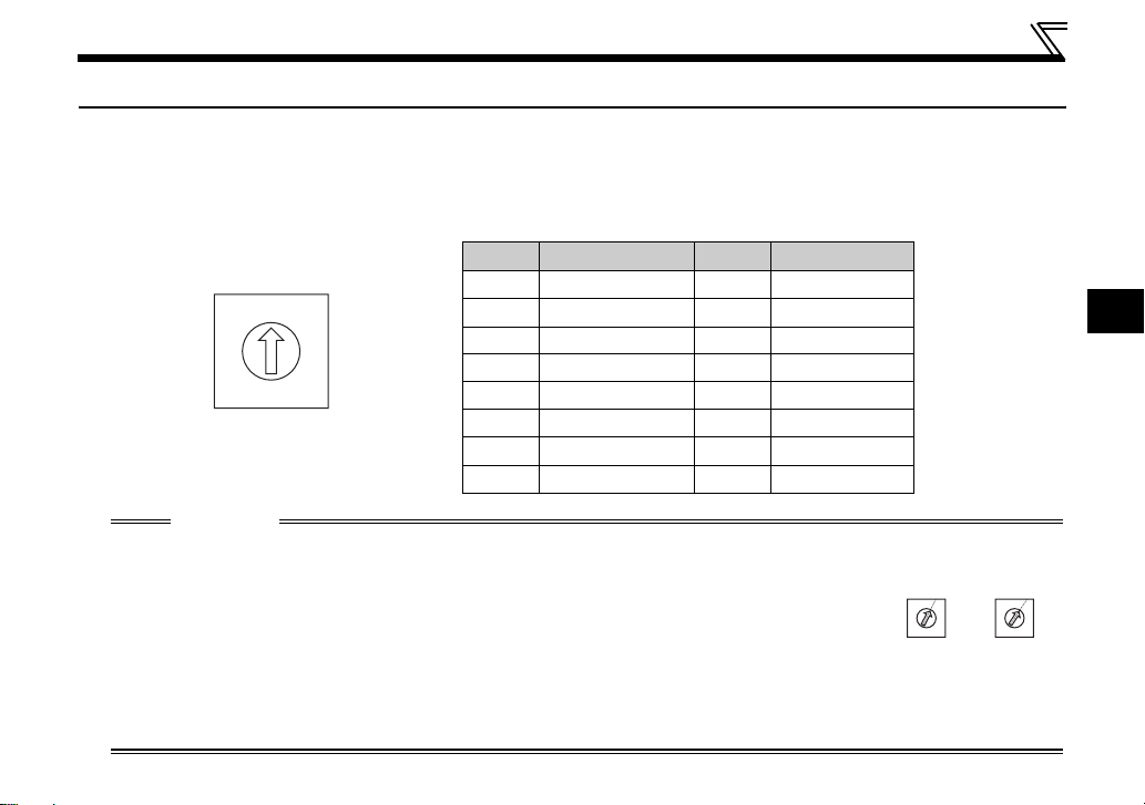
2.2 Shaft number Setting
ySetting with shaft number switch
Set the shaft number between "0H to FH" using shaft number switches on the FR-A7NS (refer to page 4).
The setting is reflected at the next power-on or inverter reset.
Set the arrow (×) of the corresponding switches to the number and alphabet to set a desired shaft
number.
No. Definition No. Definition
0 1st axis 8 9th axis
0
1
F
2
E
3
C
D
4
5
B
6
7
A
8
9
Initial status
CAUTION
y Set the shaft number switch to the switch number (alphabet) position correctly. If
the switch is set between numbers, normal data communication can not be
made.
y You cannot set the same shaft number to other devices on the network. (Doing so disables proper
communication.)
y Set the inverter shaft number before switching on the inverter and do not change the setting while
power is on. Otherwise you may get an electric shock.
1 2nd axis 9 10th axis
2 3rd axis A 11th axis
3 4th axis B 12th axis
4 5th axis C 13th axis
5 6th axis D 14th axis
6 7th axis E 15th axis
7 8th axis F 16th axis
Good
example
1
0
F
2
E
3
D
4
5
C
B
6
7
A
8
9
example
Bad
0
F
E
D
C
B
A
9
2
1
2
3
4
5
6
7
8
13
INSTALLATION
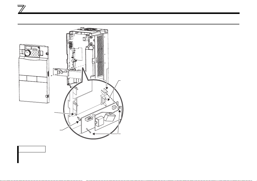
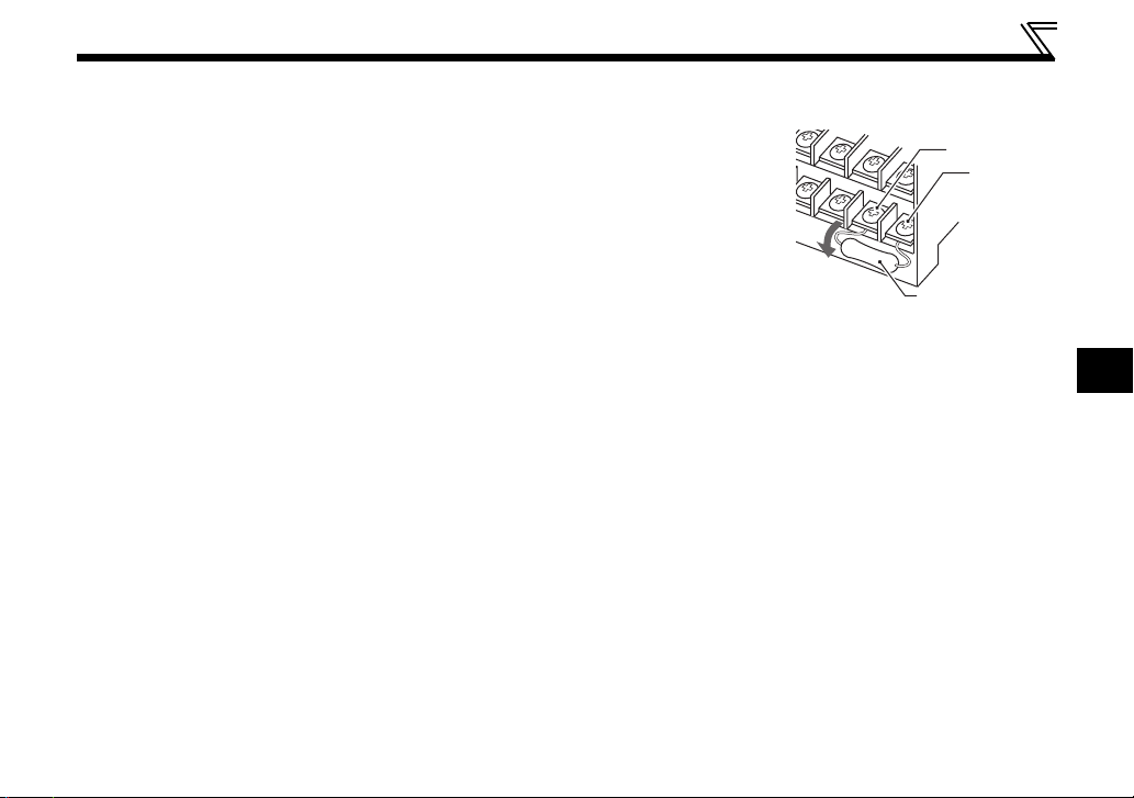
2.3 Installation Procedure
1)Remove the inverter front cover.
1)
Screw hole for
option mounting
Inverter side
option
connector
3)
Screw hole for
option mounting
(on earth plate)
Hex-head screw
for option mounting
REMARKS
y Remove a plug-in option after removing two screws on both left and right sides.
(The plug-in option is easily removed if the control circuit terminal block is removed before.)
2)
4) Mounting
screws
2)Mount the hex-head screw for option
mounting into the inverter screw hole
(on earth plate). (size 5.5mm,
tightening torque 0.56N⋅m to 0.75N⋅m)
3)Securely fit the connector of the plug-in
option to the inverter connector along
the guides.
4)Securely fix the both right and left sides
of the plug-in option to the inverter with
the accessory mounting screws.
(Tightening torque 0.45N⋅m to
0.55N⋅m) If the screw holes do not lineup, the connector may not have been
plugged snugly. Check for loose
plugging.
14
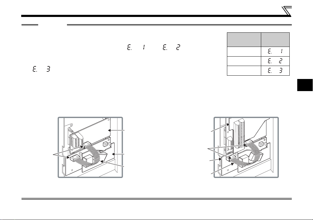
INSTALLATION
CAUTION
y When using this option unit, mount it in the "option connector 3 (lowermost
connector)" of the inverter.
If it is fitted in option connector 1 or 2, " " or " " (option alarm)
is displayed and the inverter will not function. In addition, when the inverter can
not recognize that the option is mounted due to improper installation, etc.,
" " (option alarm) is displayed even if the option is fitted in the option
connector 3.
y Mount the FR-A7AP/FR-A7AL to the "option connector 2" of the inverter.
y After mounting both of the FR-A7NS and FR-A7AP/FR-A7AL, connect each external connector using the FR-
A7AP connection cable (Refer to page 3) / FR-A7NS connection cable (enclosed in FR-A7AL, refer to the instruction
manual of FR-A7AL.) respectively.
Mounting
Position
Connector 1
Connector 2
Connector 3
Error
Display
2
When using FR-A7AP
FR-A7AP
External
connector
y Take care not to drop a hex-head screw for option mounting or mounting screw during mounting and removal.
y Pull out the option straight to remove. Otherwise, the connector may be damaged.
FR-A7NS
FR-A7AP
connection
cable
FR-A7AL
External
connector
FR-A7NS
FR-A7NS
connection
cable
When using FR-A7AL
15
3 WIRING
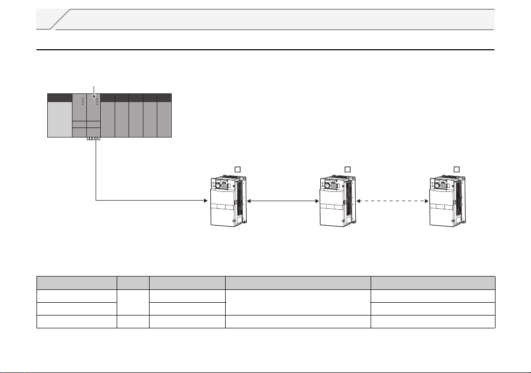
3.1 System configuration (when FR-A7AP is used)
zConnecting with the motion controller
Motion controller
(Q173DCPU/Q172DCPU)
Inverter
FR-A700 series
+ FR-A7NS + FR-A7AP
(or servo amplifier
MR-J3- B)
SSCNET ΙΙΙ cable *2 SSCNET ΙΙΙ cable *2 SSCNET ΙΙΙ cable *2
1st axis 2nd axis 16th axis *1
*1 The maximum number of inverter (or servo amplifier) connected differs depending on the type of motion controller
(Q173DCPU/Q172DCPU).
*2 For the distance between electrodes of SSCNET ΙΙΙ cable, refer to the following table.
Cable Model Name Type Cable Length (m) Distance Between Electrodes (m)
MR-J3BUSM
MR-J3BUSM-A 5 to 20 Standard cable outside panel
MR-J3BUSM-B HPCF 30 to 50 50 Long-distance cable
POF
0.15 to 3
20
Inverter
FR-A700 series
+ FR-A7NS + FR-A7AP
(or servo amplifier
MR-J3- B)
Inverter
FR-A700 series
+ FR-A7NS + FR-A7AP
(or servo amplifier
MR-J3- B)
Applications
Standard code inside panel
16
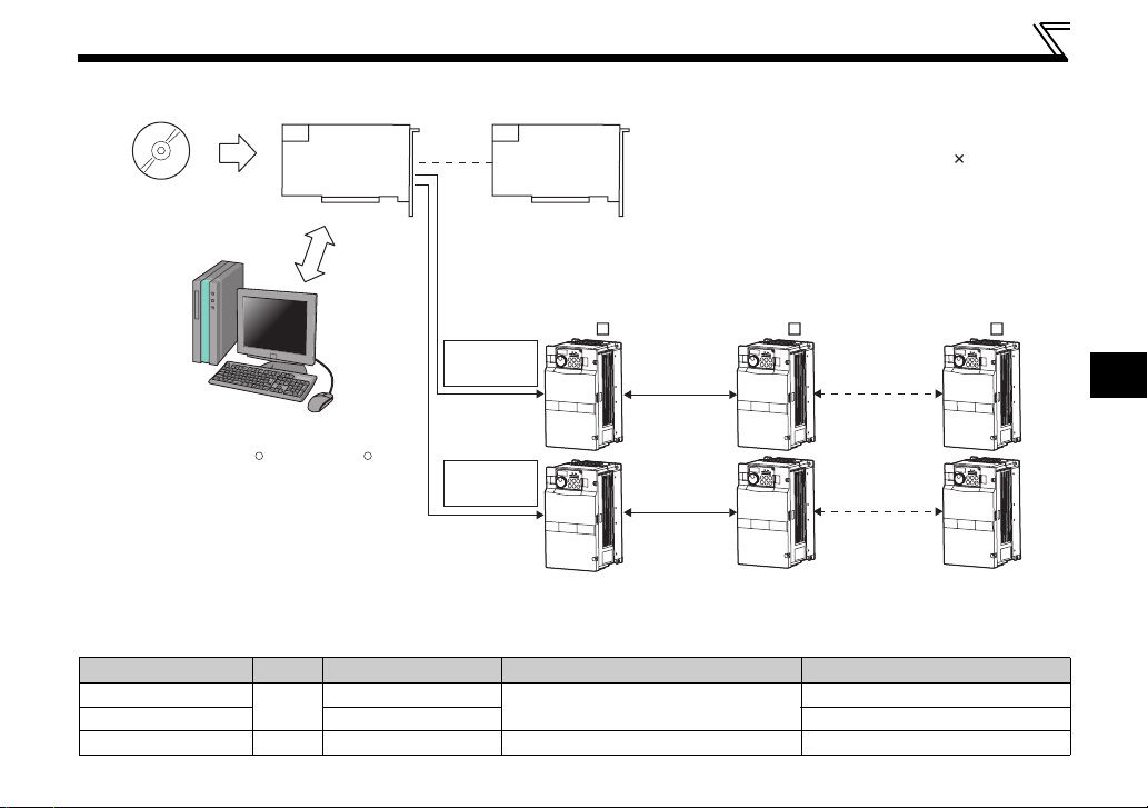
zConnecting with the motion board
Motion board(Q111BD-SSC/Q110BD-SSC)
Inverter OS software
(For the A7NS)
WIRING
Number of mountable boards:
4 boards maximum (128 axis total (32 axis 4 boards))
Specify board ID using the board ID setting switch of the
motion board.
PCI bus
Personal computer
(PC/AT compatible)
(Windows 2000 /Windows XP )
R R
Inverter
FR-A700 series
+ FR-A7NS + FR-A7AP
(or servo amplifier
MR-J3- B)
SSCNET ΙΙΙ
(Line 1)
SSCNET ΙΙΙ
cable *2
SSCNET ΙΙΙ
(Line 2)
SSCNET ΙΙΙ
cable *2
SSCNET ΙΙΙ
cable *2
SSCNET ΙΙΙ
cable *2
1st axis 2nd axis 16th axis *1
Inverter
FR-A700 series
+ FR-A7NS + FR-A7AP
(or servo amplifier
MR-J3- B)
SSCNET ΙΙΙ
cable *2
SSCNET ΙΙΙ
cable *2
Inverter
FR-A700 series
+ FR-A7NS + FR-A7AP
(or servo amplifier
MR-J3- B)
*1 The maximum number of inverter (or servo amplifier) connected differs depending on the type of motion board
(Q111BD-SSC/Q110BD-SSC).
*2 For the distance between electrodes of SSCNET ΙΙΙ cable, refer to the following table.
Cable Model Name Type Cable Length (m)
MR-J3BUSM
MR-J3BUSM-A 5 to 20 Standard cable outside panel
POF
0.15 to 3
Distance Between Electrodes (m)
20
Application
Standard code inside panel
MR-J3BUSM-B HPCF 30 to 50 50 Long-distance cable
17
3
WIRING
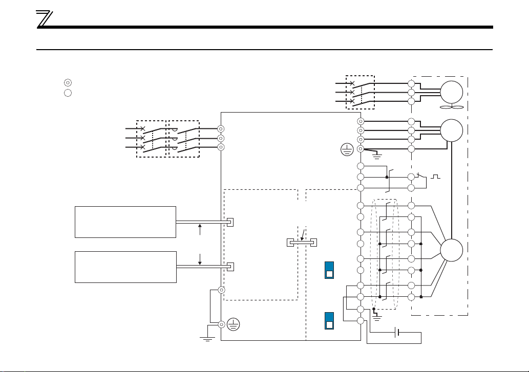
3.2 Wiring example (when FR-A7AP is used)
zVector control dedicated motor (SF-V5RU, SF-THY), 12V complementary
*1
*2
CS(OH)
PA1
PA2
PB1
PB2
PZ1
Differential
PZ2
resistor
ON
OFF
MCCB
W
PC
SD
PG
SD
PG
SD
*8*6
Sink logic
Main circuit terminal
Control circuit terminal
Three-phase
AC power supply
Servo system controller,
preceding axis inverter
(servo amplifier)
Following axis inverter
(servo amplifier)
MCCB
MC
SSCNET ΙΙΙ
cable
Three-phase
AC power supply
R/L1
S/L2
T/L3
SSCNET ΙΙΙ unit
FR-A7NS
SSCNET III
cable connector
(CN1A)
FR-A7AP
connector
SSCNET III
cable connector
(CN1B)
Earth terminal
Inverter
External
thermal
relay input
FR-A7AP
FR-A7AP
connection
cable
Complementary
Terminating
U
V
SF-V5RU, SF-THY
A
B
C
U
V
W
E
Earth
Thermal relay
(Ground)
2W1kΩ
*5
(+) (-) 12VDC power supply
G1
G2
A
B
C
D
F
G
S
R
protector
*3
FAN
IM
Encoder
*4
*7
18
WIRING
*1 For the fan of the 7.5kW or less dedicated motor, the power supply is single phase. (200V/50Hz, 200 to 230V/
60Hz)
*2 Assign OH (external thermal input) signal to the terminal CS. (Set "7" in Pr. 186 )
Connect a 2W1kΩ resistor between the terminal PC and CS (OH). Install the
resistor pushing against the bottom part of the terminal block so as to avoid a
contact with other cables.
Refer to FR-A700 Instruction Manual (Applied) for details of Pr.186 CS terminal
function selection.
CS(OH)
PC
Control circuit
terminal block
Resistor (2W1kΩ)
*3 The pin number differs according to the encoder used.
Speed control and torque control are properly performed even without connecting Z phase.
*4 Connect the encoder so that there is no looseness between the motor and motor shaft. Speed ratio should be 1:1.
*5 Earth (Ground) the shielded cable of the encoder cable to the enclosure with a P clip, etc.
(Refer to FR-A7AP Instruction Manual.)
*6 For the complementary, set the terminating resistor selection switch to off position.
(Refer to FR-A7AP Instruction Manual.)
*7 A separate power supply of 5V/12V/15V/24V is necessary according to the encoder power specification.
*8 For terminal compatibility of the FR-JCBL, FR-V7CBL and FR-A7AP, refer to FR-A7AP Instruction Manual.
19
3

WIRING
3.3 SSCNET III cable
Use our optional SSCNET ΙΙΙ connection cables.
(1) Cable type
Cable Model Name *1 Type Cable Length (m) Flex Life Application
MR-J3BUSM
MR-J3BUSM-A 5, 10, 20 Standard
MR-J3BUSM-B *2 HPCF 30, 40, 50 Long flex
*1 in the type represents the cable length.
Symbol 015 03 05 1 3 5 10 20 30 40 50
Cable Length (m) 0.15 0.3 0.5 1 3 5 10 20 30 40 50
*2 For cable of 30m or less, contact our company.
POF
0.15, 0.3, 0.5, 1, 3 Standard
Standard code inside panel
Standard cable outside panel
Long-distance cable
20
 Loading...