

Page 1

INVERTER
FR-A701
INSTRUCTION MANUAL (BASIC)
FR-A721-5.5K to 55K
FR-A741-5.5K to 55K
Thank you for choosing this Mitsubishi Inverter.
This Instruction Manual is intended for users who "just want to run the inverter".
If you are going to utilize functions and performance, refer to the FR-A701 Series Instruction Manual (Applied) [IB0600337ENG]. The Instruction Manual (Applied) is separately available from where you purchased the inverter or
your Mitsubishi sales representative.
CONTENTS
1
OUTLINE ....................................................................................................... 1
1.1 Product checking and parts identification .........................................................................1
1.2 Inverter and peripheral devices.........................................................................................2
1.3 Method of removal and reinstallation of the front cover....................................................4
1.4 Installation of the inverter and enclosure design ..............................................................6
2
WIRING........................................................................................................ 12
2.1 Terminal connection diagram......................................................................................... 12
2.2 Main circuit terminal specifications................................................................................. 13
2.3 Control circuit specifications........................................................................................... 20
2.4 Connection of motor with encoder (vector control) ........................................................ 28
3
PRECAUTIONS FOR USE OF THE INVERTER......................................... 35
3.1 EMC and leakage currents ............................................................................................ 35
3.2 Power-off and magnetic contactor (MC)........................................................................ 41
3.3 Inverter-driven 400V class motor ................................................................................... 42
3.4 Precautions for use of the inverter ................................................................................. 43
3.5 Failsafe of the system which uses the inverter .............................................................. 45
4
DRIVING THE MOTOR ............................................................................... 47
4.1 Step of operation ............................................................................................................47
4.2 Operation panel (FR-DU07)........................................................................................... 48
4.3 Before operation.............................................................................................................56
4.4 Start/stop from the operation panel (PU operation mode)............................................. 83
4.5 Start and stop using terminals (External operation)....................................................... 92
4.6 Parameter List .............................................................................................................. 100
5
TROUBLESHOOTING .............................................................................. 141
5.1 Reset method of protective function ............................................................................ 141
5.2 List of fault or alarm display ......................................................................................... 142
5.3 Causes and corrective actions..................................................................................... 143
5.4 Correspondences between digital and actual characters............................................ 159
5.5 Check and clear of the faults history..................................................................... 160
5.6 Check first when you have a trouble............................................................................ 162
6
PRECAUTIONS FOR MAINTENANCE AND INSPECTION..................... 170
6.1 Inspection item ............................................................................................................. 170
6.2 Measurement of main circuit voltages, currents and powers ...................................... 177
7
SPECIFICATIONS..................................................................................... 182
7.1 Rating ........................................................................................................................... 182
7.2 Common specifications ................................................................................................ 184
7.3 Outline dimension drawings......................................................................................... 185
7.4 Installation of the heatsink portion outside the enclosure for use................................ 194
701
1
2
3
4
5
6
7
Page 2
This Instruction Manual (Basic) provides handling information and precautions for use of the equipment.
Please forward this Instruction Manual (Basic) to the end user.
This section is specifically about safety matters
Do not attempt to install, operate, maintain or inspect the
inverter until you have read through the Instruction Manual
and appended documents carefully and can use the
equipment correctly. Do not use this product until you have
a full knowledge of the equipment, safety information and
instructions.
In this Instruction Manual, the safety instruction levels are
classified into "WARNING" and "CAUTION".
WARNING
CAUTION
CAUTION
The level may even lead to a serious
consequence according to conditions. Both instruction
levels must be followed because these are important to
personal safety.
Incorrect handling may cause
hazardous conditions, resulting in
death or severe injury.
Incorrect handling may cause
hazardous conditions, resulting in
medium or slight injury, or may cause
only material damage.
1. Electric Shock Prevention
WARNING
z While power is ON or when the inverter is running, do not
open the front cover. Otherwise you may get an electric
shock.
z Do not run the inverter with the front cover or wiring cover
removed. Otherwise you may access the exposed highvoltage terminals or the charging part of the circuitry and
get an electric shock.
z Even if power is OFF, do not remove the front cover
except for wiring or periodic inspection. You may
accidentally touch the charged inverter circuits and get an
electric shock.
z Before wiring or inspection, power must be switched OFF.
To confirm that, LED indication of the operation panel
must be checked. (It must be OFF.) Any person who is
involved in wiring or inspection shall wait for at least 10
minutes after the power supply has been switched OFF
and check that there are no residual voltage using a tester
or the like. The capacitor is charged with high voltage for
some time after power OFF, and it is dangerous.
z
This inverter must be earthed (grounded). Earthing
(grounding) must conform to the requirements of national
and local safety regulations and electrical code (NEC section
250, IEC 536 class 1 and other applicable standards).
A neutral-point earthed (grounded) power supply for 400V
class inverter in compliance with EN standard must be used.
z Any person who is involved in wiring or inspection of this
equipment shall be fully competent to do the work.
z The inverter must be installed before wiring. Otherwise
you may get an electric shock or be injured.
z Setting dial and key operations must be performed with
dry hands to prevent an electric shock.
z Do not subject the cables to scratches, excessive stress,
heavy loads or pinching. Otherwise you may get an
electric shock.
z Do not change the cooling fan while power is ON. It is
dangerous to change the cooling fan while power is ON.
z Do not touch the printed circuit board or handle the
cables with wet hands. Otherwise you may get an electric
shock.
z When measuring the main circuit capacitor capacity, the
DC voltage is applied to the motor for 1s at powering OFF.
Never touch the motor terminal, etc. right after powering
OFF to prevent an electric shock.
2. Fire Prevention
CAUTION
z Inverter must be installed on a nonflammable wall without
holes (so that nobody touches the inverter heatsink on the
rear side, etc.). Mounting it to or near flammable material
can cause a fire.
z If the inverter has become faulty, the inverter power must
be switched OFF. A continuous flow of large current could
cause a fire.
3.Injury Prevention
CAUTION
z The voltage applied to each terminal must be the ones
specified in the Instruction Manual. Otherwise burst,
damage, etc. may occur.
z The cables must be connected to the correct terminals.
Otherwise burst, damage, etc. may occur.
z Polarity must be correct. Otherwise burst, damage, etc.
may occur.
z While power is ON or for some time after power-OFF, do
not touch the inverter as they will be extremely hot. Doing
so can cause burns.
4. Additional Instructions
Also the following points must be noted to prevent an
accidental failure, injury, electric shock, etc.
(1) Transportation and Mounting
CAUTION
z The product must be transported in correct method that
corresponds to the weight. Failure to do so may lead to
injuries.
z Do not stack the boxes containing inverters higher than
the number recommended.
z The product must be installed to the position where
withstands the weight of the product according to the
information in the Instruction Manual.
z Do not install or operate the inverter if it is damaged or
has parts missing.
z When carrying the inverter, do not hold it by the front
cover or setting dial; it may fall off or fail.
z Do not stand or rest heavy objects on the product.
z The inverter mounting orientation must be correct.
z Foreign conductive objects must be prevented from
entering the inverter. That includes screws and metal
fragments or other flammable substance such as oil.
z As the inverter is a precision instrument, do not drop or
subject it to impact.
z The inverter must be used under the following
environment. Otherwise the inverter may be damaged.
Surrounding
air
temperature
Ambient
humidity
Storage
temperature
Atmosphere
Environment
Altitude/
vibration
∗1 Temperature applicable for a short time, e.g. in transit.
-10°C to +50°C (non-freezing)
90%RH or less (non-condensing)
-20°C to +65°C *1
Indoors (free from corrosive gas, flammable gas,
oil mist, dust and dirt)
Maximum 1,000m above sea level for standard
operation.
2
or less at 10 to 55Hz (directions of X, Y, Z
5.9m/s
axes)
(2) Wiring
CAUTION
z Do not install a power factor correction capacitor or surge
suppressor/capacitor type filter on the inverter output
side. These devices on the inverter output side may be
overheated or burn out.
z The connection orientation of the output cables U, V, W to
the motor affects the rotation direction of the motor.
A-1
Page 3
(3) Trial run
CAUTION
z Before starting operation, each parameter must be
confirmed and adjusted. A failure to do so may cause
some machines to make unexpected motions.
(4) Usage
WARNING
z Any person must stay away from the equipment when the
retry function is set as it will restart suddenly after trip.
z Since pressing key may not stop output depending
on the function setting status, separate circuit and switch
that make an emergency stop (power OFF, mechanical
brake operation for emergency stop, etc.) must be
provided.
z OFF status of the start signal must be confirmed before
resetting the inverter fault. Resetting inverter alarm with
the start signal ON restarts the motor suddenly.
z
The inverter must be used for three-phase induction motors.
Connection of any other electrical equipment to the
inverter output may damage the equipment.
z Performing pre-excitation (LX signal and X13 signal)
under torque control (Real sensorless vector control) may
start the motor running at a low speed even when the start
command (STF or STR) is not input. The motor may also
run at a low speed when the speed limit value = 0 with a
start command input. It must be confirmed that the motor
running will not cause any safety problem before
performing pre-excitation.
z Do not modify the equipment.
z
Do not perform parts removal which is not instructed in this
manual. Doing so may lead to fault or damage of the product.
(5) Emergency stop
CAUTION
z A safety backup such as an emergency brake must be
provided to prevent hazardous condition to the machine
and equipment in case of inverter failure.
z When the breaker on the inverter input side trips, the
wiring must be checked for fault (short circuit), and
internal parts of the inverter for a damage, etc. The cause
of the trip must be identified and removed before turning
ON the power of the breaker.
z When any protective function is activated, appropriate
corrective action must be taken, and the inverter must be
reset before resuming operation.
(6) Maintenance, inspection and parts replacement
CAUTION
z Do not carry out a megger (insulation resistance) test on
the control circuit of the inverter. It will cause a failure.
(7) Disposal
CAUTION
z The inverter must be treated as industrial waste.
General instruction
Many of the diagrams and drawings in this Instruction
Manual (Basic) show the inverter without a cover or partially
open for explanation. Never operate the inverter in this
manner. The cover must be always reinstalled and the
instruction in this Instruction Manual (Basic) must be
followed when operating the inverter.
CAUTION
z The electronic thermal relay function does not guarantee
protection of the motor from overheating. It is
recommended to install both an external thermal and PTC
thermistor for overheat protection.
z Do not use a magnetic contactor on the inverter input for
frequent starting/stopping of the inverter. Otherwise the
life of the inverter decreases.
z The effect of electromagnetic interference must be
reduced by using a noise filter or by other means.
Otherwise nearby electronic equipment may be affected.
z When driving a 400V class motor by the inverter, the
motor must be an insulation-enhanced motor or measures
must be taken to suppress surge voltage. Surge voltage
attributable to the wiring constants may occur at the
motor terminals, deteriorating the insulation of the motor.
z When parameter clear or all parameter clear is performed,
the required parameters must be set again before starting
operations because all parameters return to the initial value.
z The inverter can be easily set for high-speed operation.
Before changing its setting, the performances of the
motor and machine must be fully examined.
z Stop status cannot be hold by the inverter's brake
function. In addition to the inverter’s brake function, a
holding device must be installed to ensure safety.
z Before running an inverter which had been stored for a long
period, inspection and test operation must be performed.
z For prevention of damage due to static electricity, nearby
metal must be touched before touching this product to
eliminate static electricity from your body.
A-2
Page 4

— CONTENTS —
1OUTLINE 1
1.1 Product checking and parts identification .............................................................. 1
1.2 Inverter and peripheral devices..............................................................................2
1.2.1 Peripheral devices ..................................................................................................................... 3
1.3 Method of removal and reinstallation of the front cover......................................... 4
1.4 Installation of the inverter and enclosure design.................................................... 6
1.4.1 Inverter installation environment................................................................................................ 6
1.4.2 Cooling system types for inverter enclosure.............................................................................. 9
1.4.3 Inverter placement ................................................................................................................... 10
2WIRING 12
2.1 Terminal connection diagram...............................................................................12
2.2 Main circuit terminal specifications ...................................................................... 13
2.2.1 Specification of main circuit terminal ....................................................................................... 13
2.2.2 Terminal arrangement of the main circuit terminal, power supply and the motor wiring ......... 14
2.2.3 Cables and wiring length ......................................................................................................... 16
2.2.4 When connecting the control circuit and the main circuit separately
to the power supply ................................................................................................................. 19
2.3 Control circuit specifications ................................................................................ 20
2.3.1 Control circuit terminals ........................................................................................................... 20
2.3.2 Changing the control logic ....................................................................................................... 23
2.3.3 Control circuit terminal layout .................................................................................................. 25
2.3.4 Wiring instructions ................................................................................................................... 25
2.3.5 When connecting the operation panel using a connection cable ............................................ 26
2.3.6 RS-485 terminal block ............................................................................................................. 26
2.3.7 Communication operation........................................................................................................ 27
2.3.8 USB connector ........................................................................................................................ 27
CONTENTS
2.4 Connection of motor with encoder (vector control) .............................................. 28
3 PRECAUTIONS FOR USE OF THE INVERTER 35
3.1 EMC and leakage currents ..................................................................................35
3.1.1 Leakage currents and countermeasures ................................................................................. 35
3.1.2 EMC measures ........................................................................................................................ 37
3.1.3 Power supply harmonics ......................................................................................................... 39
3.1.4 Harmonic suppression guideline .............................................................................................39
3.2 Power-off and magnetic contactor (MC) ..............................................................41
3.3 Inverter-driven 400V class motor ......................................................................... 42
3.4 Precautions for use of the inverter ....................................................................... 43
3.5 Failsafe of the system which uses the inverter .................................................... 45
I
Page 5

4 DRIVING THE MOTOR 47
4.1 Step of operation.................................................................................................. 47
4.2 Operation panel (FR-DU07)................................................................................. 48
4.2.1 Parts of the operation panel (FR-DU07) .................................................................................. 48
4.2.2 Basic operation (factory setting) .............................................................................................. 49
4.2.3 Operation lock (Press [MODE] for an extended time (2s)) ...................................................... 50
4.2.4 Monitoring of output current and output voltage ...................................................................... 51
4.2.5 First priority monitor ................................................................................................................. 51
4.2.6 Setting dial push ...................................................................................................................... 51
4.2.7 Changing the parameter setting value..................................................................................... 52
4.2.8 Parameter clear, all parameter clear .......................................................................................53
4.2.9 Parameter copy and parameter verification............................................................................. 54
4.3 Before operation ..................................................................................................56
4.3.1 Simple mode parameter list ..................................................................................................... 56
4.3.2 Overheat protection of the motor by the inverter (Pr. 9) .......................................................... 57
4.3.3 When the rated motor frequency is 50Hz (Pr. 3) .................................................................... 58
4.3.4 Increase the starting torque (Pr. 0) ......................................................................................... 59
4.3.5 Limit the maximum and minimum output frequency (Pr. 1, Pr. 2) ........................................... 60
4.3.6 Change acceleration and deceleration time (Pr. 7, Pr. 8)........................................................ 61
4.3.7 Selection of the start command and frequency command locations (Pr. 79) .......................... 62
4.3.8 Large starting torque and low speed torque are necessary (Advanced magnetic
flux vector control, Real sensorless vector control) (Pr. 71, Pr. 80, Pr. 81, Pr. 800) ............. 63
4.3.9 Higher accuracy operation using a motor with encoder (Vector control)
(Pr.71, Pr.80, Pr.81, Pr.359, Pr.369, Pr.800) .......................................................................... 66
4.3.10 Exhibiting the best performance of the motor performance (offline auto tuning)
(Pr. 71, Pr. 83, Pr. 84, Pr. 96) .............................................................................................. 71
4.3.11 High accuracy operation unaffected by the motor temperature
(online auto tuning) (Pr. 95) ................................................................................................ 76
4.3.12 To perform high accuracy/fast response operation (gain adjustment of Real
sensorless vector control and vector control) (Pr. 818 to Pr. 821, Pr. 880) .......................... 77
4.4 Start/stop from the operation panel (PU operation mode) ...................................83
4.4.1 Setting the set frequency to operate (example: performing operation at 30Hz) ...................... 83
4.4.2 Use the setting dial like a potentiometer to perform operation. ............................................... 85
4.4.3 Setting the frequency by switches (three-speed setting) ......................................................... 86
4.4.4 Setting the frequency by analog input (voltage input) ............................................................. 88
4.4.5 Setting the frequency by analog input (current input) .............................................................. 90
4.5 Start and stop using terminals (External operation) ............................................. 92
4.5.1 Setting the frequency by the operation panel (Pr. 79 = 3) ....................................................... 92
4.5.2 Setting the frequency by switches (three-speed setting) (Pr. 4 to Pr. 6) ................................. 94
4.5.3 Setting the frequency by analog input (voltage input) ............................................................. 96
4.5.4 Changing the frequency (60Hz, initial value) at the maximum voltage input
(5V, initial value) ...................................................................................................................... 97
4.5.5 Setting the frequency by analog input (current input) .............................................................. 98
4.5.6 Changing the frequency (60Hz, initial value) at the maximum current input
(at 20mA, initial value) ............................................................................................................. 99
4.6 Parameter List.................................................................................................... 100
4.6.1 List of parameters classified by the purpose ......................................................................... 100
4.6.2 Parameter list ........................................................................................................................ 103
II
Page 6

5 TROUBLESHOOTING 141
5.1 Reset method of protective function .................................................................. 141
5.2 List of fault or alarm display ...............................................................................142
5.3 Causes and corrective actions...........................................................................143
5.4 Correspondences between digital and actual characters .................................. 159
5.5 Check and clear of the faults history.................................................................. 160
5.6 Check first when you have a trouble.................................................................. 162
5.6.1 Motor does not start............................................................................................................... 162
5.6.2 Motor or machine is making abnormal acoustic noise........................................................... 164
5.6.3 Inverter generates abnormal noise........................................................................................ 164
5.6.4 Motor generates heat abnormally.......................................................................................... 165
5.6.5 Motor rotates in the opposite direction .................................................................................. 165
5.6.6 Speed greatly differs from the setting .................................................................................... 165
5.6.7 Acceleration/deceleration is not smooth ................................................................................ 166
5.6.8 Motor current is too large....................................................................................................... 166
5.6.9 Speed does not accelerate .................................................................................................... 167
5.6.10 Motor and machine vibrate .................................................................................................... 167
5.6.11 Speed varies during operation............................................................................................... 168
5.6.12 Operation mode is not changed properly .............................................................................. 169
5.6.13 Operation panel (FR-DU07) display is not operating............................................................. 169
5.6.14 Power lamp is not lit .............................................................................................................. 169
5.6.15 Unable to write parameter setting.......................................................................................... 169
CONTENTS
6 PRECAUTIONS FOR MAINTENANCE AND INSPECTION 170
6.1 Inspection item...................................................................................................170
6.1.1 Daily inspection ..................................................................................................................... 170
6.1.2 Periodic inspection ................................................................................................................ 170
6.1.3 Daily and periodic inspection................................................................................................. 171
6.1.4 Display of the life of the inverter parts ................................................................................... 172
6.1.5 Checking the inverter and converter modules ....................................................................... 173
6.1.6 Cleaning ................................................................................................................................ 174
6.1.7 Replacement of parts ............................................................................................................ 174
6.2 Measurement of main circuit voltages, currents and powers............................. 177
6.2.1 Measurement of powers ........................................................................................................ 179
6.2.2 Measurement of voltages and use of PT ............................................................................... 179
6.2.3 Measurement of currents....................................................................................................... 180
6.2.4 Use of CT and transducer ..................................................................................................... 180
6.2.5 Measurement of inverter input power factor .......................................................................... 180
6.2.6 Measurement of converter output voltage (across terminals P/+ and N/-) ............................ 181
6.2.7 Measurement of inverter output frequency ............................................................................ 181
6.2.8 Insulation resistance test using megger ................................................................................ 181
6.2.9 Pressure test ......................................................................................................................... 181
III
Page 7

7 SPECIFICATIONS 182
7.1 Rating................................................................................................................. 182
7.1.1 Inverter rating ........................................................................................................................ 182
7.1.2 Motor rating ........................................................................................................................... 183
7.2 Common specifications...................................................................................... 184
7.3 Outline dimension drawings...............................................................................185
7.3.1 Inverter outline dimension drawings ...................................................................................... 185
7.3.2 Dedicated motor outline dimension drawings ........................................................................ 190
7.4 Installation of the heatsink portion outside the enclosure for use ...................... 194
7.4.1 Protrusion of heatsink ............................................................................................................ 194
APPENDICES 196
Appendix 1 Main differences and compatibilities with the FR-A700 series ................. 196
Appendix 2 Instructions for compliance with the EU Directives (400V class only)..... 197
Appendix 3 Instructions for UL and cUL Compliance................................................. 199
Appendix 4 Control mode-based parameter (function) correspondence
table and instruction code list ................................................................... 201
<Abbreviations>
DU: Operation panel (FR-DU07)
PU: Operation panel (FR-DU07) and parameter unit (FR-PU04, FR-PU07)
Inverter: Mitsubishi inverter FR-A701 series
FR-A701: Mitsubishi inverter FR-A701 series
Pr.: Parameter Number (Number assigned to function)
PU operation: Operation using the PU (FR-DU07/FR-PU04/FR-PU07)
External operation: Operation using the control circuit signals
Combined operation: Combined operation using the PU (FR-DU07/FR-PU04/FR-PU07) and external operation
Standard motor: SF-JR
Constant-torque motor: SF-HRCA
Vector dedicated motor: SF-V5RU
<Trademarks>
ONWORKS
L
DeviceNet is a registered trademark of ODVA (Open DeviceNet Vender Association, Inc.).
Company and product names herein are the trademarks and registered trademarks of their respective owners.
REMARKS
⋅ For differences and compatibility between the FR-A701 series and FR-A700 series, refer to page 196.
®
is registered trademarks of Echelon Corporation in the U.S.A. and other countries.
IV
Page 8
Product checking and parts identification
1 OUTLINE
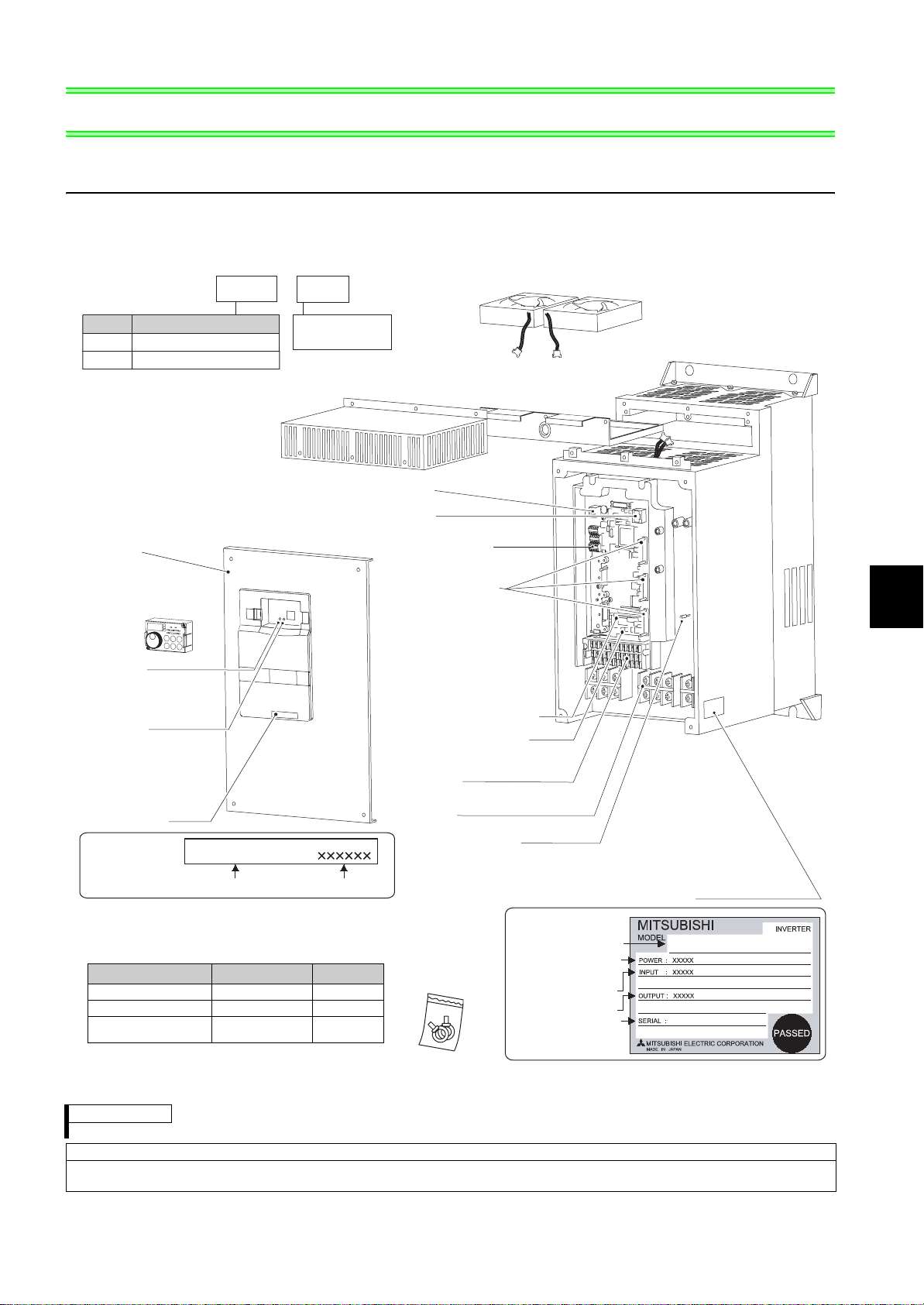
1.1 Product checking and parts identification
Unpack the inverter and check the capacity plate on the front cover and the rating plate on the inverter side face to
ensure that the product agrees with your order and the inverter is intact.
• Inverter Model
--
FR
A721
5.5
K
Cooling fan
(Refer to page 175)
Symbol
A721
Front cover
(Refer to page 4)
Operation panel
(FR-DU07)
Power lamp
Lit when the control circuit
(R1/L11, S1/L21) is supplied
with power.
Alarm lamp
Lit when the inverter is
in the alarm status
(major fault).
Capacity plate
Capacity plate
Voltage Class
Three-phase 200V class
Three-phase 400V classA741
(Refer to page 48)
FR-A721-5.5K
Inverter Model
Indicate inverter
capacity (kW)
Serial number
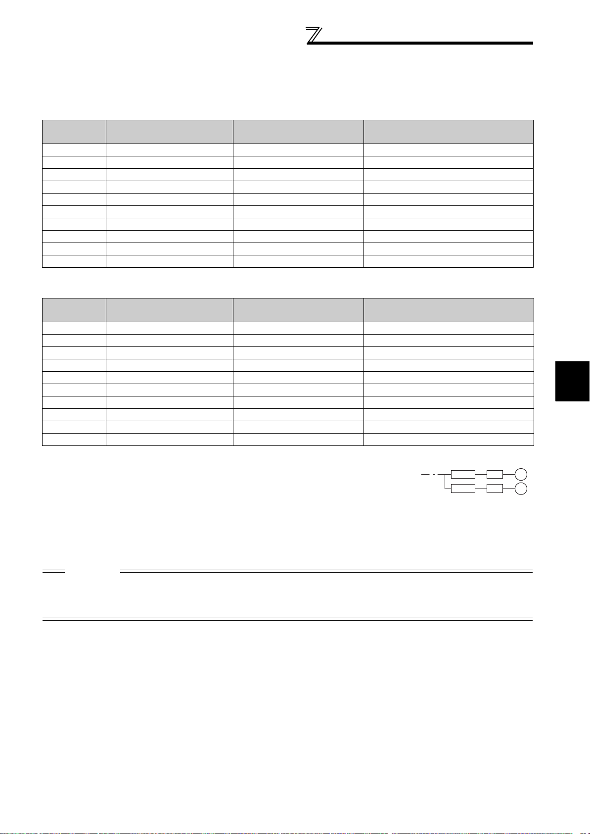
• Accessory
· Eyebolt for hanging the inverter
Capacity Eyebolt size Quantity
11K , 1 5 K M8 2
18.5K to 30K M10 2
37K to 55K M12 2
* The 5.5K and 7.5K are not provided with eyebolts.
(Refer to page 175)
USB connector
(Refer to page 337)
PU connector
(Refer to page 22)
RS-485 terminals
(Refer to page 26)
Connector for plug-in
option connection
(Refer to the Instruction Manual
of options.)
There are three connection
connectors and they are called
connector 1, connector 2, and
connector 3 from the top.
Voltage/current input switch
(Refer to page 12)
AU/PTC switchover switch
(Refer to Chapter 4 of the
Instruction Manual (Applied).)
Control circuit
terminal block
Main circuit
terminal block
(Refer to page 20)
Charge lamp
Lit when power is supplied
to the main circuit
Fan blockFan cover
(Refer to page 175)
(Refer to page 13)
Rating plate
Inverter Model
Applied motor
Output rating
Serial number
1
OUTLINE
(Refer to page 13)
Rating plate
FR-A721-5.5K
capacity
Input rating
REMARKS
For removal and reinstallation of covers, refer to page 4.
Harmonic suppression guideline (when inverters are used in Japan)
All models of general-purpose inverters used by specific consumers are covered by "Harmonic suppression guideline for consumers
who receive high voltage or special high voltage". (For details, refer to page 39 .)
1
Page 9
Inverter and peripheral devices
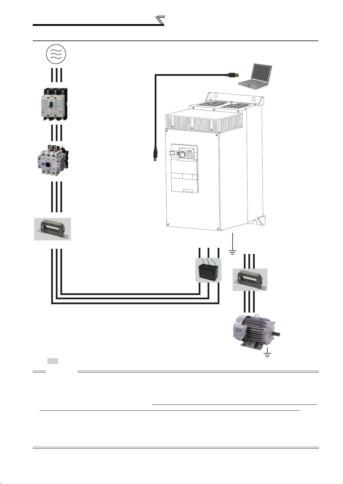
1.2 Inverter and peripheral devices
Three-phase AC power supply
Use within the permissible power supply
specifications of the inverter.
(Refer to page 182)
Moulded case circuit breaker (MCCB) or
earth leakage circuit breaker (ELB), fuse
The breaker must be selected carefully
since an in-rush current flows in the inverter
at power on.
(Refer to page 3)
Magnetic contactor (MC)
Install the magnetic contactor to ensure
safety. Do not use this magnetic contactor
to start and stop the inverter. Doing so will
cause the inverter life to be shorten.
(Refer to page 3)
USB connector
A personal computer and an inverter
can be connected with a
USB (Ver1. 1) cable.
(Refer to page 27)
Inverter (FR-A701)
The life of the inverter is
influenced by surrounding air
temperature. The surrounding
air temperature should be as low
as possible within the
permissible range. This must be
noted especially when the
inverter is installed in an
enclosure. (Refer to page 6)
Wrong wiring might lead to
damage of the inverter. The
control signal lines must be kept
fully away from the main circuit
to protect them from noise.(Refer
to page 12)
EMC filter (ferrite core)
(FR-BLF)
Install a noise filter to reduce the electromagnetic
noise generated from the inverter.
Effective in the range from about 1MHz to 10MHz.
When more wires are passed through, a more
effective result can be obtained. The total number of
wires passed through should be 4T or more.
EMC filter (capacitor)
(FR-BIF)
Reduces the radio noise.
Devices connected to the output
Do not install a power factor correction capacitor, surge suppressor or radio noise filter on the output
side of the inverter. When installing a moulded case circuit breaker on the output side of the inverter,
contact each manufacturer for selection of the moulded case circuit breaker.
Earth (Ground)
To prevent an electric shock, always earth (ground) the motor and inverter.
: Install these options as required.
R/L1 S/L2 T/L3
Earth
(Ground)
UWV
Earth (Ground)
EMC filter (ferrite core)
(FR-BLF)
Install a noise filter to
reduce the
electromagnetic noise
generated from the
inverter.
Effective in the range
from about 1MHz to
10MHz. A wire should be
wound four turns at a
maximum.
Motor
CAUTION
·
Do not install a power factor correction capacitor, surge suppressor or radio noise filter on the inverter output side. This will cause the
inverter to trip or the capacitor, and surge suppressor to be damaged. If any of the above devices are connected, immediately remove them.
· This inverter has a built-in AC reactor (FR-HAL) and a circuit type specified in Harmonic suppression guideline in Japan is threephase bridge (capacitor smoothed) and with reactor (AC side). (Refer to page 39) Do not use an AC reactor (FR-HAL) of a standalone option except following purpose. (Note that overload protection of the converter may operate when a thyristor load is
connected in the power supply system. To prevent this, always install an optional stand-alone AC reactor (FR-HAL).) A DC
reactor (FR-HEL) can not be connected to the inverter.
· Electromagnetic wave interference
The input/output (main circuit) of the inverter includes high frequency components, which may interfere with the communication
devices (such as AM radios) used near the inverter. In this case, connecting a capacitor type filter will reduce electromagnetic
wave interference.
· Refer to the instruction manual of each option and peripheral devices for details of peripheral devices.
2
Page 10
Inverter and peripheral devices
1.2.1 Peripheral devices
Check the inverter model of the inverter you purchased. Appropriate peripheral devices must be selected according to
the capacity. Refer to the following list and prepare appropriate peripheral devices:
200V class
Motor Output
(kW)
*1
5.5 FR-A721-5.5K 40A S-N20, N21
7.5 FR-A721-7.5K 50A S-N25
11 FR-A721-11K 75A S-N35
15 FR-A721-15K 100A S-N50
18.5 FR-A721-18.5K 125A S-N50
22 FR-A721-22K 150A S-N65
30 FR-A721-30K 175A S-N80
37 FR-A721-37K 225A S-N125
45 FR-A721-45K 300A S-N150
55 FR-A721-55K 350A S-N180
400V class
Motor Output
(kW)
*1
5.5 FR-A741-5.5K 20A S-N11, N12
7.5 FR-A741-7.5K 30A S-N20, N21
11 FR-A741-11K 40A S-N20, N21
15 FR-A741-15K 50A S-N20, N21
18.5 FR-A741-18.5K 60A S-N25
22 FR-A741-22K 75A S-N25
30 FR-A741-30K 100A S-N50
37 FR-A741-37K 125A S-N50
45 FR-A741-45K 150A S-N65
55 FR-A741-55K 175A S-N80
*1 Selections for use of the Mitsubishi 4-pole standard motor with power supply voltage of 200VAC/400VAC 50Hz.
*2 Select the MCCB according to the inverter power supply capacity.
Install one MCCB per inverter.
For the use in the United States or Canada, provide the appropriate UL and cUL listed Class RK5 or Class T
type fuse or UL 489 molded case circuit breaker (MCCB) that is suitable for branch circuit protection.
(Refer to page 199.)
*3 Magnetic contactor is selected based on the AC-1 class. The electrical durability of magnetic contactor is 500,000 times. When the magnetic
contactor is used for emergency stop during motor driving, the electrical durability is 25 times.
When using the MC for emergency stop during motor driving or using on the motor side during commercial-power supply operation, select the MC
with class AC-3 rated current for the motor rated current.
Applicable Inverter Model Breaker Selection*2 Input Side Magnetic Contactor*3
Applicable Inverter Model Breaker Selection*2 Input Side Magnetic Contactor*3
MCCB INV
MCCB INV
IM
IM
1
OUTLINE
CAUTION
· When the inverter capacity is larger than the motor capacity, select an MCCB and a magnetic contactor according to the
inverter model and cable according to the motor output.
· When the breaker on the inverter input side trips, check for the wiring fault (short circuit), damage to internal parts of the
inverter, etc. Identify the cause of the trip, then remove the cause and power on the breaker.
3
Page 11
Method of removal and reinstallation of
the front cover
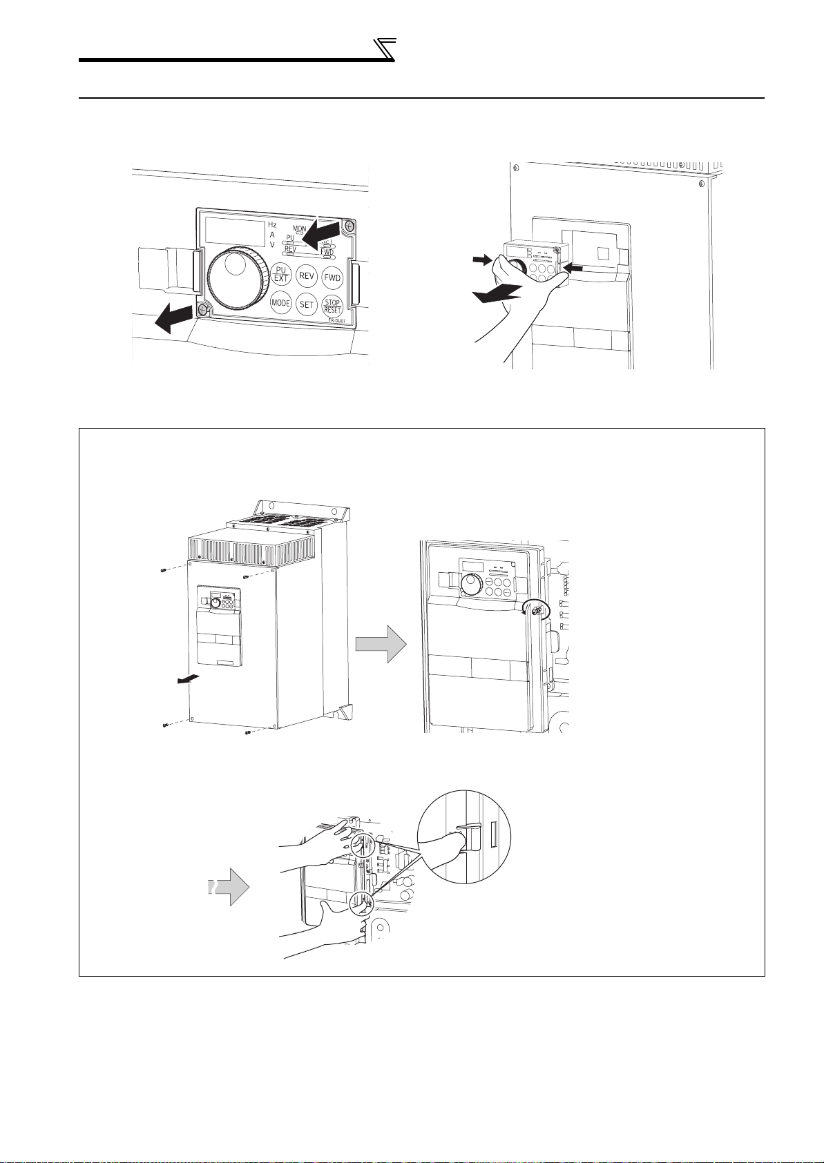
1.3 Method of removal and reinstallation of the front cover
•Removal of the operation panel
1) Loosen the two screws on the operation panel.
(These screws cannot be removed.)
When reinstalling the operation panel, insert it straight to reinstall securely and tighten the fixed screws of the
operation panel.
2) Push the left and right hooks of the operation panel
and pull the operation panel toward you to remove.
•Removal of the front cover
1) Remove installation screws on the front cover
1 to remove the front cover 1.
Front cover 1
3) Pull the front cover 2 toward you to remove by pushing an installation hook on the right side
using left fixed hooks as supports.
2) Loosen the installation screws of the
front cover 2.
Front cover 2
Installation hook
4
Page 12
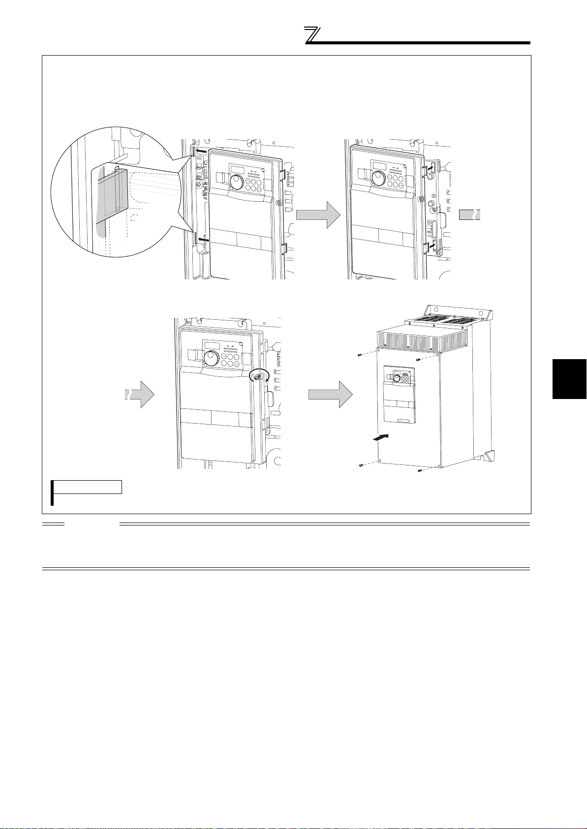
•Reinstallation of the front cover
1) Insert the two fixed hooks on the left side of the
front cover 2 into the sockets of the inverter.
3) Fix the front cover 2 with the installation screws. 4) Fix the front cover 1 with the installation
Method of removal and reinstallation of
the front cover
2) Using the fixed hooks as supports, securely press the
front cover 2 against the inverter.
(Although installation can be done with the operation
panel mounted, make sure that a connector is
securely fixed.)
Front cover 2 Front cover 2
screws.
Front cover 2
Front cover 1
REMARKS
· For the 55K, the front cover 1 is separated into two parts.
CAUTION
1. Fully make sure that the front cover has been reinstalled securely. Always tighten the installation screws of the front cover.
2. The same serial number is printed on the capacity plate of the front cover and the rating plate of the inverter. Before
reinstalling the front cover, check the serial numbers to ensure that the cover removed is reinstalled to the inverter from where
it was removed.
1
OUTLINE
5
Page 13
Installation of the inverter and enclosure
design
1.4 Installation of the inverter and enclosure design
When an inverter enclosure is to be designed and manufactured, heat generated by contained equipment, etc., the
environment of an operating place, and others must be fully considered to determine the enclosure structure, size and
equipment layout. The inverter unit uses many semiconductor devices. To ensure higher reliability and long period of
operation, operate the inverter in the ambient environment that completely satisfies the equipment specifications.
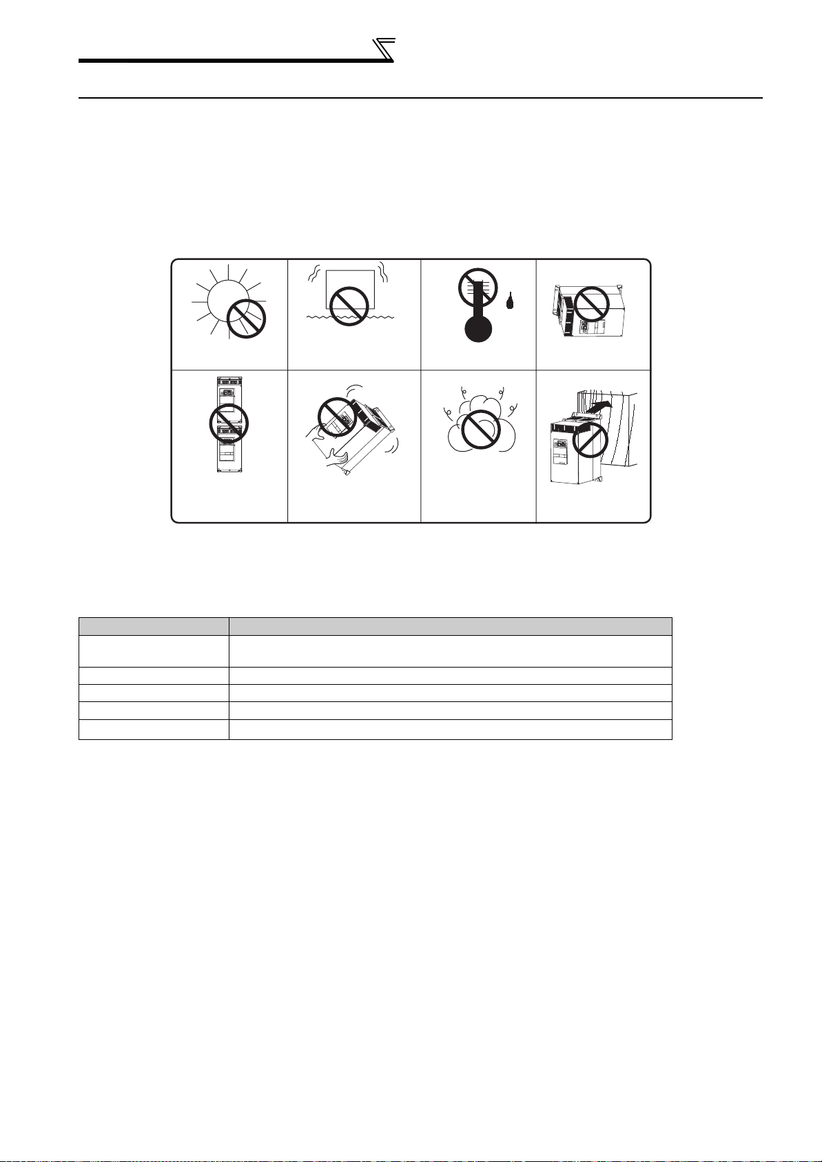
1.4.1 Inverter installation environment
The inverter consists of precision mechanical and electronic parts. Never install or handle it in any of the following
conditions as doing so could cause an operation fault or failure.
Vibration (5.9m/s2 or more
Direct sunlight
at 10 to 55Hz (directions of
X, Y, Z axes))
High temperature,
high humidity
Horizontal placement
Vertical mounting
(When installing two or
more inverters, install
them in parallel.)
Transportation by
holding the front cover
Oil mist, flammable
gas, corrosive gas,
fluff, dust, etc.
Mounting to
combustible material
As the inverter installation environment should satisfy the standard specifications indicated in the following table,
operation in any place that does not meet these conditions not only deteriorates the performance and life of the
inverter, but also causes a failure. Refer to the following points and take adequate measures.
Environmental standard specifications of inverter
Item Description
Surrounding air
temperature
Ambient humidity 90% RH maximum (non-condensing)
Atmosphere Free from corrosive and explosive gases, dust and dirt
Maximum Altitude 1,000m or less
Vibration
-10°C to +50°C (non-freezing)
2
5.9m/s
or less at 10 to 55Hz (directions of X, Y, Z axes)
6
Page 14

Installation of the inverter and enclosure
design
(1) Temperature
The permissible surrounding air temperature of the inverter is between -10°C and +50°C. Always operate the inverter
within this temperature range. Operation outside this range will considerably shorten the service lives of the
semiconductors, parts, capacitors and others. Take the following measures so that the surrounding air temperature of
the inverter falls within the specified range.
1) Measures against high temperature
• Use a forced ventilation system or similar cooling system. (Refer to page 9.)
• Install the enclosure in an air-conditioned electrical chamber.
• Block direct sunlight.
• Provide a shield or similar plate to avoid direct exposure to the radiated heat and wind of a heat source.
• Ventilate the area around the enclosure well.
2) Measures against low temperature
• Provide a space heater in the enclosure.
• Do not power off the inverter. (Keep the start signal of the inverter off.)
3) Sudden temperature changes
• Select an installation place where temperature does not change suddenly.
• Avoid installing the inverter near the air outlet of an air conditioner.
• If temperature changes are caused by opening/closing of a door, install the inverter away from the door.
(2) Humidity
Normally operate the inverter within the 45 to 90% range of the ambient humidity. Too high humidity will pose problems
of reduced insulation and metal corrosion. On the other hand, too low humidity may produce a spatial electrical
breakdown. The insulation distance specified in JEM1103 "Control Equipment Insulator" is defined as humidity 45 to
85%.
1) Measures against high humidity
• Make the enclosure enclosed, and provide it with a hygroscopic agent.
• Take dry air into the enclosure from outside.
• Provide a space heater in the enclosure.
2) Measures against low humidity
What is important in fitting or inspection of the unit in this status is to discharge your body (static electricity)
beforehand and keep your body from contact with the parts and patterns, besides blowing air of proper humidity into
the enclosure from outside.
3) Measures against condensation
Condensation may occur if frequent operation stops change the in-enclosure temperature suddenly or if the outsideair temperature changes suddenly.
Condensation causes such faults as reduced insulation and corrosion.
• Take the measures against high humidity in 1).
• Do not power off the inverter. (Keep the start signal of the inverter off.)
1
OUTLINE
(3) Dust, dirt, oil mist
Dust and dirt will cause such faults as poor contact of contact points, reduced insulation or reduced cooling effect due
to moisture absorption of accumulated dust and dirt, and in-enclosure temperature rise due to clogged filter.
In the atmosphere where conductive powder floats, dust and dirt will cause such faults as malfunction, deteriorated
insulation and short circuit in a short time.
Since oil mist will cause similar conditions, it is necessary to take adequate measures.
Countermeasures
• Place in a totally enclosed enclosure.
Take measures if the in-enclosure temperature rises. (Refer to page 9.)
• Purge air.
Pump clean air from outside to make the in-enclosure pressure higher than the outside-air pressure.
7
Page 15

Installation of the inverter and enclosure
design
(4) Corrosive gas, salt damage
If the inverter is exposed to corrosive gas or to salt near a beach, the printed board patterns and parts will corrode or
the relays and switches will result in poor contact.
In such places, take the measures given in Section (3).
(5) Explosive, flammable gases
As the inverter is non-explosion proof, it must be contained in an explosion proof enclosure.
In places where explosion may be caused by explosive gas, dust or dirt, an enclosure cannot be used unless it
structurally complies with the guidelines and has passed the specified tests. This makes the enclosure itself expensive
(including the test charges).
The best way is to avoid installation in such places and install the inverter in a non-hazardous place.
(6) Highland
Use the inverter at the altitude of within 1000m.
If it is used at a higher place, it is likely that thin air will reduce the cooling effect and low air pressure will deteriorate
dielectric strength.
(7) Vibration, impact
The vibration resistance of the inverter is up to 5.9m/s2 at 10 to 55Hz frequency (directions of X, Y, Z axes) and 1mm
amplitude.
Vibration or impact, if less than the specified value, applied for a long time may make the mechanism loose or cause
poor contact to the connectors.
Especially when impact is imposed repeatedly, caution must be taken as the part pins are likely to break.
Countermeasures
• Provide the enclosure with rubber vibration isolators.
• Strengthen the structure to prevent the enclosure from resonance.
• Install the enclosure away from sources of vibration.
8
Page 16
Installation of the inverter and enclosure
design
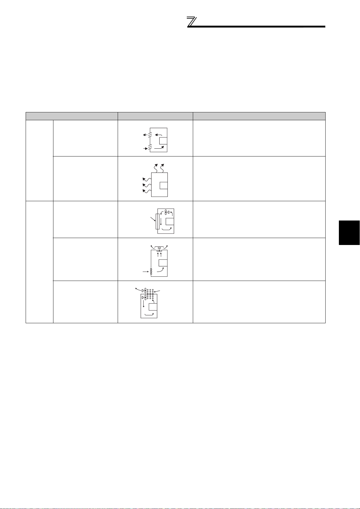
1.4.2 Cooling system types for inverter enclosure
From the enclosure that contains the inverter, the heat of the inverter and other equipment (transformers, lamps,
resistors, etc.) and the incoming heat such as direct sunlight must be dissipated to keep the in-enclosure temperature
lower than the permissible temperatures of the in-enclosure equipment including the inverter.
The cooling systems are classified as follows in terms of the cooling calculation method.
1) Cooling by natural heat dissipation from the enclosure surface (Totally enclosed type)
2) Cooling by heat sink (Aluminum heatsink, etc.)
3) Cooling by ventilation (Forced ventilation type, pipe ventilation type)
4) Cooling by heat exchanger or cooler (Heat pipe, cooler, etc.)
Cooling System Enclosure Structure Comment
Natural
cooling
Forced
cooling
Natural ventilation
(Enclosed, open type)
Natural ventilation (Totally
enclosed type)
Heatsink cooling
Forced ventilation
Heat pipe Totally enclosed type for enclosure downsizing.
Heatsink
INV
INV
INV
INV
Heat
pipe
INV
Low in cost and generally used, but the enclosure size
increases as the inverter capacity increases. For
relatively small capacities.
Being a totally enclosed type, the most appropriate for
hostile environment having dust, dirt, oil mist, etc. The
enclosure size increases depending on the inverter
capacity.
Having restrictions on the heatsink mounting position
and area, and designed for relative small capacities.
For general indoor installation. Appropriate for enclosure
downsizing and cost reduction, and often used.
1
OUTLINE
9
Page 17
Installation of the inverter and enclosure
design
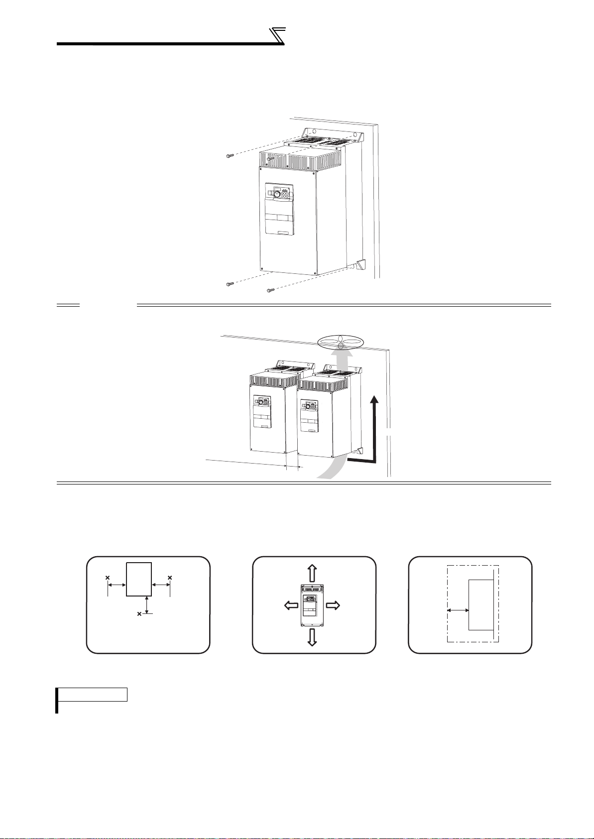
1.4.3 Inverter placement
(1) Installation of the Inverter
Installation on the enclosure
CAUTION
⋅ When encasing multiple inverters, install them in parallel as a cooling measure.
⋅ Install the inverter vertically.
Vertical
Refer to the clearances below.
(2) Clearances around the inverter
To ensure ease of heat dissipation and maintenance, leave at least the shown clearances around the inverter. At least the
following clearances are required under the inverter as a wiring space, and above the inverter as a heat dissipation space.
Surrounding air temperature and humidity
Measurement
position
Inverter
5cm
Measurement
position
5cm
5cm
Temperature: -10°C to 50°C
Ambient humidity: 90% RH
5cm
or more
10cm or more
5cm
or more
10cm or more
maximum
Leave enough clearances and take
cooling measures.
REMARKS
For replacing the cooling fan, 30cm of space is necessary in front of the inverter. Refer to page 175 for fan replacement.
Clearances (side)Clearances (front)
5cm
Inverter
or
more
(3) Inverter mounting orientation
Mount the inverter on a wall as specified. Do not mount it horizontally or any other way.
10
Page 18
Installation of the inverter and enclosure
design
(4) Above the inverter
Heat is blown up from inside the inverter by the small fan built in the unit. Any equipment placed above the inverter
should be heat resistant.
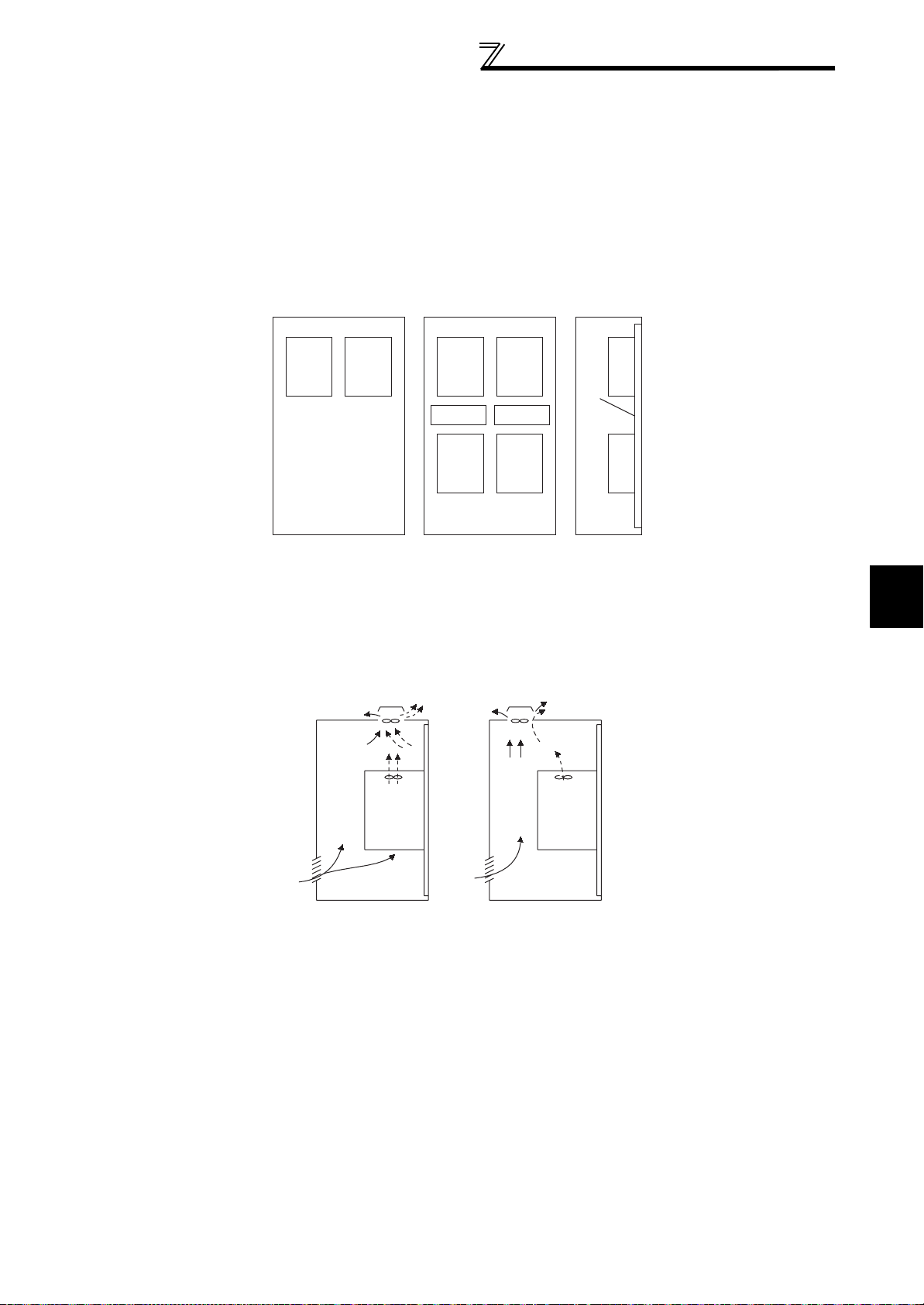
(5) Arrangement of multiple inverters
When multiple inverters are placed in the same enclosure, generally arrange them horizontally as shown in the figure
below (a). When it is inevitable to arrange them vertically to minimize space, take such measures as to provide guides
since heat from the bottom inverters can increase the temperatures in the top inverters, causing inverter failures.
When mounting multiple inverters, fully take caution not to make the surrounding air temperature of the inverter higher
than the permissible value by providing ventilation and increasing the enclosure size.
InverterInverterInverter Inverter
Guide Guide
Inverter
Enclosure Enclosure
(a) Horizontal arrangement (b) Vertical arrangement
Arrangement of multiple inverters
Inverter
Guide
(6) Placement of ventilation fan and inverter
Heat generated in the inverter is blown up from the bottom of the unit as warm air by the cooling fan. When installing a
ventilation fan for that heat, determine the place of ventilation fan installation after fully considering an air flow. (Air
passes through areas of low resistance. Make an airway and airflow plates to expose the inverter to cool air.)
Inverter Inverter
1
OUTLINE
<Good example> <Bad example>
Placement of ventilation fan and inverter
11
Page 19
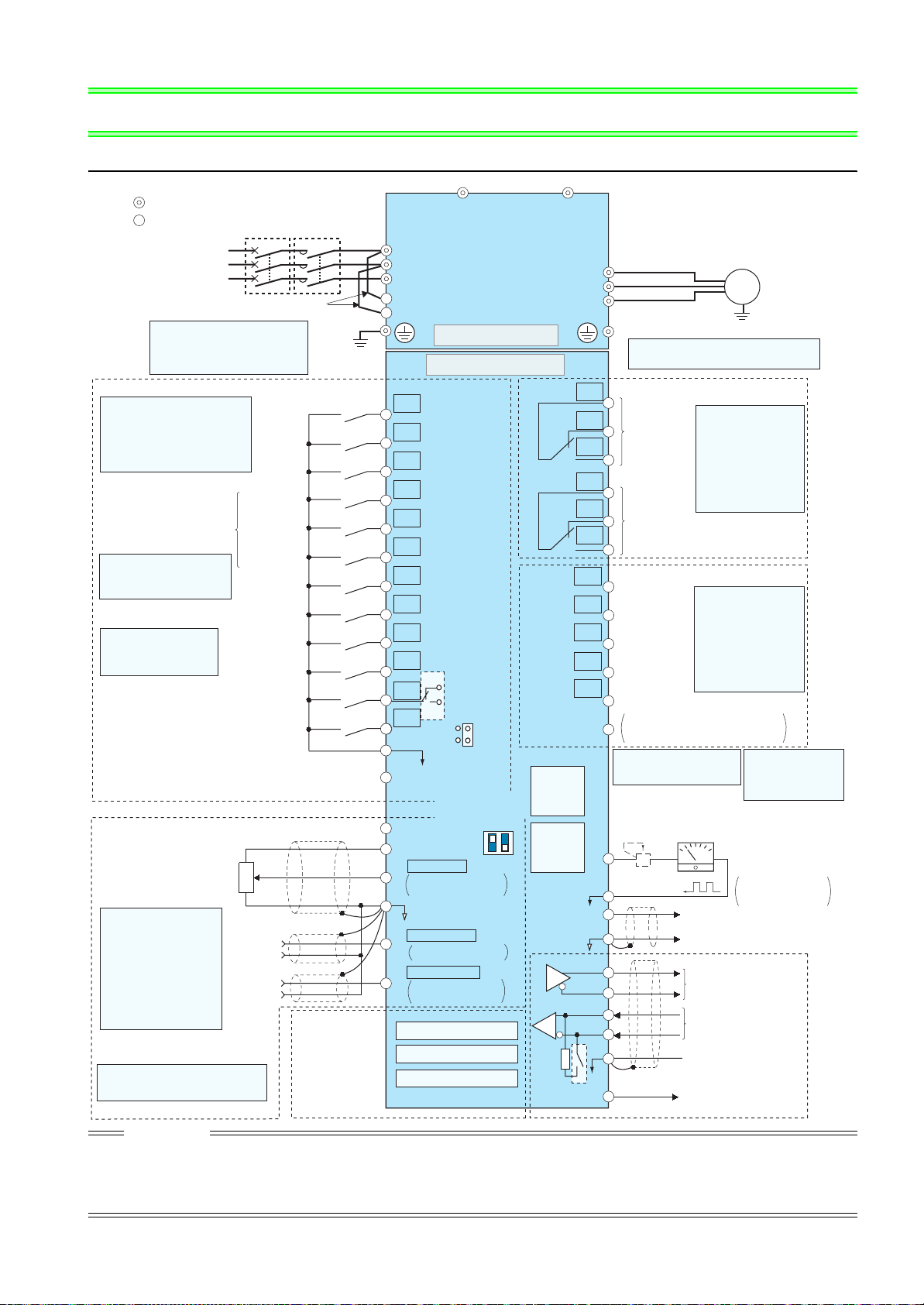
Terminal connection diagram
2 WIRING
2.1 Terminal connection diagram
Sink logic
Main circuit terminal
Control circuit terminal
MCCB
MC
*6 *6
R/L1
Three-phase AC
power supply
Jumper
*1. To supply power to the
control circuit separately,
remove the jumper across
R1/L11 and S1/L21.
Control input signals (No voltage input allowed)
Terminal functions vary with
the input terminal
assignment (Pr. 178 to Pr. 189)
(Refer to Chapter 4 of the Instruction
Manual (Applied))
Forward
rotation
start
Reverse
rotation
start
Start self-
holding selection
High speed
Multi-speed
selection
*2. JOG terminal can be used
as pulse train input terminal.
Use Pr. 291 to select
JOG/pulse.
Middle
speed
Low speed
Jog operation
Second function selection
*3. AU terminal can be
used as PTC input
terminal.
Terminal 4 input selection
(Current input selection)
Selection of automatic restart
Output stop
Reset
after instantaneous
power failure
Contact input common
24VDC power supply
(Common for external power supply transistor)
Frequency setting signal (Analog)
Frequency setting
potentiometer
1/2W1k
*
Terminal input specifications
4.
can be changed by analog
input specifications
switchover (Pr. 73, Pr. 267).
Set the voltage/current input
switch in the OFF position to
select voltage input (0 to 5V/0
to10V) and ON to select
current input (4 to 20mA).
(Refer to Chapter 4 of the
Instruction Manual (Appl ied))
*5
3
Ω
1
Auxiliary
input
Terminal
4 input
(Current
input)
2
(+)
(-)
(+)
(-)
Connector
for plug-in option
connection
*5
. It is recommended to use 2W1kΩ
when the frequency setting signal
is changed frequently.
*1
Earth
(Ground)
S/L2
T/L3
R1/L11
S1/L21
Main circuit
Control circuit
STF
STR
STOP
RH
RM
RL
JOG
*2
RT
MRS
RES
*3
AU
AU
PTC
CS
SD
PC
10E(+10V)
10(+5V)
2
5
1
4
Option connector 1
Option connector 2
Option connector 3
SOURCE
*4
Voltage/current
input switch
ON
OFF
0 to 5VDC
0 to 10VDC
0 to 20mADC
(Initial value)
selectable
(Analog common)
±
10VDC
0 to
0 to ±5VDC
selectable
4 to 20mADC
0 to 5VDC
0 to 10VDC
selectable
SINK
2
4
*4
(Initial value)
*4
(Initial value)
*4
CAUTION
· To prevent a malfunction due to noise, keep the signal cables more than 10cm away from the power cables. Also separate the main circuit wire
of the input side and the output side.
· After wiring, wire offcuts must not be left in the inverter.
Wire offcuts can cause an alarm, failure or malfunction. Always keep the inverter clean.
When drilling mounting holes in an enclosure etc., take care not to allow chips and other foreign matter to enter the inverter.
· Set the voltage/current input switch correctly. Different setting may cause a fault, failure or malfunction.
N/-P/+
C1
B1
A1
C2
B2
A2
RUN
SU
IPF
OL
FU
SE
PU
connector
USB
connector
FM
SD
AM
TXD+
TXD-
RXD+
RXD-
SG
Terminating
VCC
resistor
U
V
W
*6. Do not connect any options to P/+ and
N/-.
Relay output 1
(Fault output)
Terminal functions
vary with the output
terminal assignment
(Pr. 195, Pr. 196)
(Refer to Chapter 4 of the
Instruction Manual
(Applied))
Relay output 2
Open collector output
Running
Up to frequency
Instantaneous
power failure
Overload
Terminal functions
vary with the output
terminal assignment
(Pr. 190 to Pr. 194)
(Refer to Chapter 4 of the
Instruction Manual
(Applied))
Frequency detection
Open collector output common
/source common
Sink
*
7. It is not necessary when
calibrating the indicator
from the operation panel.
*8
5
Calibration
resistor *7
+
-
(+)
Analog signal output
(0 to 10VDC)
(-)
RS-485 terminals
Data transmission
Data reception
GND
(Permissible load
5V
current 100mA)
Motor
IM
Earth (Ground)
Relay output
*8. FM terminal can be
used for pulse train
output of open
collector output
using Pr.291.
Indicator
(Frequency meter, etc.)
Moving-coil type
1mA full-scale
12
Page 20

2.2 Main circuit terminal specifications
2.2.1 Specification of main circuit terminal
Main circuit terminal specifications
Termina l
Symbol
R/L1,
S/L2,
T/L3
U, V, W Inverter output Connect a three-phase squirrel-cage motor.
R1/L11,
S1/L21
P/+, N/- DC terminal Do not connect any options.
Termina l N ame Description
AC power input Connect to the commercial power supply.
Connected to the AC power supply terminals R/L1 and S/L2. To retain the
fault display and fault output, remove the jumpers from terminals R/L1-R1/
L11 and S/L2-S1/L21 and apply external power to these terminals.
Do not turn off the power supply for control circuit (R1/L11, S1/L21) with the
Power supply for
control circuit
Earth (Ground)
main circuit power (R/L1, S/L2, T/L3) on. Doing so may damage the
inverter. The circuit should be configured so that the main circuit power (R/
L1, S/L2, T/L3) is also turned off when the power supply for control circuit
(R1/L11, S1/L21) is off.
The following power supply capacities are required to supply power
separately from R1/L11 and S1/L21:
90VA for 15K or lower, 100VA for 18.5K or higher
For earthing (grounding) the inverter chassis. Must be earthed
(grounded).
2
WIRING
13
Page 21
Main circuit terminal specifications
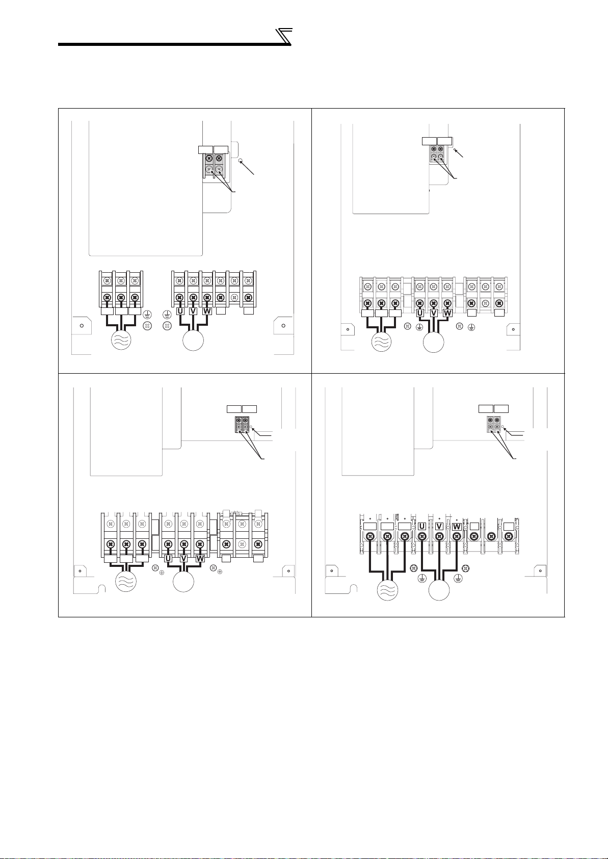
2.2.2 Terminal arrangement of the main circuit terminal, power supply and the motor wiring
200V class
FR-A721-5.5K, 7.5K FR-A721-11K, 15K
R1/L11 S1/L21
Screw size
(M4)
Screw size (M5)
R/L1 S/L2 T/L3
N/-
Charge lamp
Jumper
Screw size (M5 for 11K, M6 for 15K)
P/+
IM
Power supply
FR-A721-18.5K to 45K FR-A721-55K
Motor
Power supply
Screw size (M4)
R1/L11 S1/L21
Charge
lamp
Jumper
Screw size
R/L1 S/L2 T/L3
(M4)
R1/L11 S1/L21
Charge lamp
Jumper
N/- P/+
IM
Motor
Screw size (M4)
R1/L11 S1/L21
Charge
lamp
Jumper
Screw size
(18.5K/22K/30K: M8, 37K/45K: M10)
R/L1 S/L2
Power supply
T/L3
IM
Motor
Screw size
(M6 for 18.5K, 22K and
30K M8 for 37K and 45K)
N/-
P/+
Screw size (M12)
R/L1 S/L2 T/L3
Power supply
IM
Motor
N/-
Screw size (M8)
P/+
14
Page 22
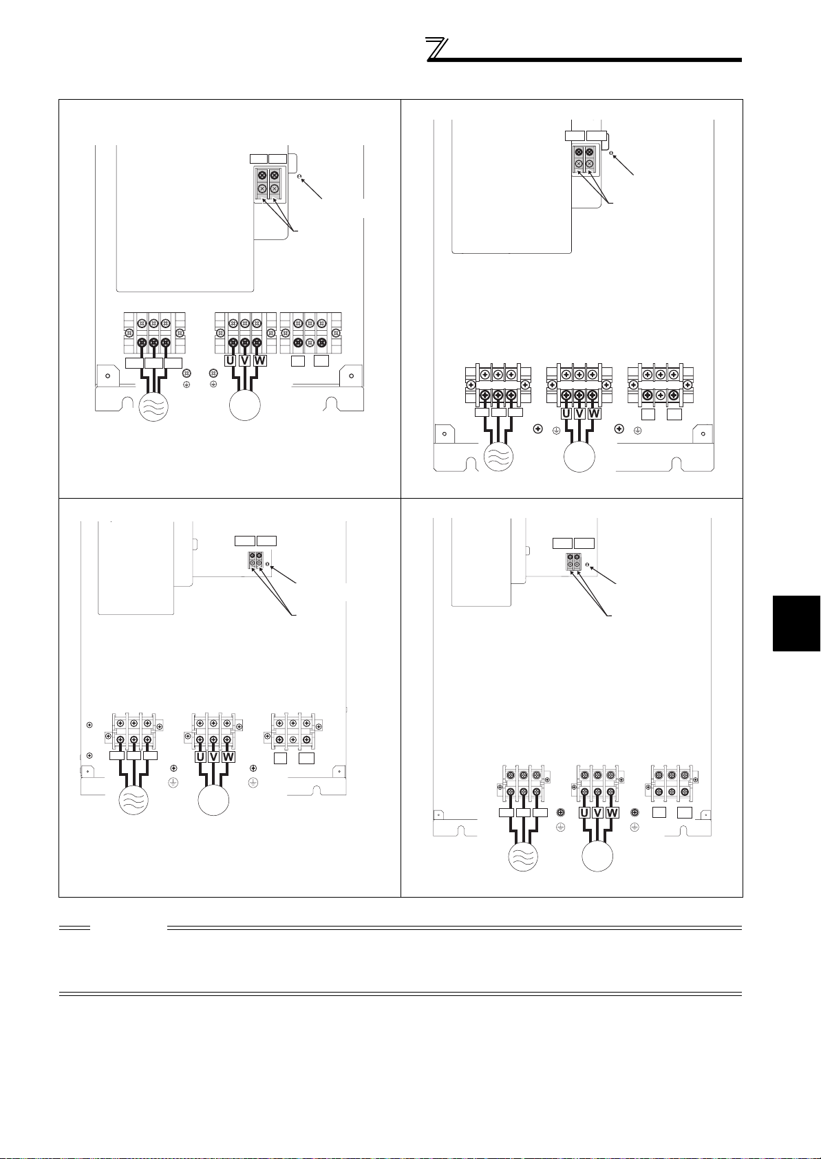
400V class
FR-A741-5.5K, 7.5K FR-A741-11K, 15K
Screw size (M4)
R1/L11
S1/L21
Charge lamp
Jumper
Screw size (M4)
Main circuit terminal specifications
S1/L21
R1/L11
Screw size (M4)
Charge lamp
Jumper
P/+
R/L1 S/L2 T/L3
N/-
IM
Power supply
FR-A741-18.5K to 45K FR-A741-55K
Screw size (M6 for 18.5K to 30K
M8 for 37K and 45K)
Motor
Screw size (M4)
S1/L21
R1/L11
Charge lamp
Jumper
Screw size (M5)
R/L1 S/L2 T/L3
Power supply
IM
Motor
S1/L21
R1/L11
P/+
N/-
Screw size (M4)
Charge lamp
Jumper
2
WIRING
R/L1 S/L2 T/L3
Power supply
IM
Motor
N/-
P/+
R/L1 S/L2 T/L3
Screw size (M8)
N/-
P/+
IM
Power supply
CAUTION
· The power supply cables must be connected to R/L1, S/L2, T/L3. (Phase sequence needs not to be matched.) Never connect
the power cable to the U, V, W of the inverter. Doing so will damage the inverter.
· Connect the motor to U, V, W. At this time, turning ON the forward rotation switch (signal) rotates the motor in the
counterclockwise direction when viewed from the motor shaft.
Motor
15
Page 23

Main circuit terminal specifications
2.2.3 Cables and wiring length
(1) Applicable cable size
Select the recommended cable size to ensure that a voltage drop will be 2% or less.
If the wiring distance is long between the inverter and motor, a main circuit cable voltage drop will cause the motor
torque to decrease especially at the output of a low frequency.
The following table indicates a selection example for the wiring length of 20m.
200V class (when input power supply is 220V)
Earthing
cable
Cable Sizes
AWG/MCM *2
R/L1,
S/L2,
U, V, W
T/L3
PVC, etc. (mm2) *3
R/L1,
S/L2,
T/L3
U, V, W
Earthing
cable
Applicable Inverter
Model
Terminal
Screw
Size *4
Tightening
Torque N · m
Crimping
Ter min al
R/L1,
S/L2,
T/L3
U, V, W
HIV, etc. (mm2) *1
R/L1,
S/L2,
T/L3
U, V, W
FR-A721-5.5K M5 2.5 5.5-5 5.5-5 5.5 5.5 5.5 10 10 6 6 6
FR-A721-7.5K M5 2.5 14-5 8-5 14 8 5.5 6 8 16 10 16
FR-A721-11K M5 2.5 14-5 14-5 14 14 14 6 6 16 16 16
FR-A721-15K M6 4.4 22-6 22-6 22 22 14 4 4 25 25 16
FR-A721-18.5K M8(M6) 7.8 38-8 38-8 38 38 22 2 2 35 35 25
FR-A721-22K M8(M6) 7.8 38-8 38-8 38 38 22 2 2 35 35 25
FR-A721-30K M8(M6) 7.8 60-8 60-8 60 60 22 1/0 1/0 50 50 25
FR-A721-37K M10(M8) 14.7 80-10 80-10 80 80 22 3/0 3/0 70 70 35
FR-A721-45K M10(M8) 14.7 100-10 100-10 100 100 38 4/0 4/0 95 95 50
FR-A721-55K M12(M8) 24.5 100-12 100-12 100 100 38 4/0 4/0 95 95 50
*1 The cable size is that of the cable (HIV cable (600V class 2 vinyl-insulated cable) etc.) with continuous maximum permissible temperature of
75°C. Assumes that the surrounding air temperature is 50°C or less and the wiring distance is 20m or less.
*2 The recommended cable size is that of the cable (THHW cable) with continuous maximum permissible temperature of 75°C. Assumes that the
surrounding air temperature is 40°C or less and the wiring distance is 20m or less.
(Selection example for use mainly in the United States.)
*3 For the 15K or lower, the recommended cable size is that of the cable (PVC cable) with continuous maximum permissible temperature of 70°C.
Assumes that the surrounding air temperature is 40°C or less and the wiring distance is 20m or less.
For the 18.5K or higher, the recommended cable size is that of the cable (XLPE cable) with continuous maximum permissible temperature of 90°C.
Assumes that the surrounding air temperature is 40°C or less and wiring is performed in an enclosure.
(Selection example for use mainly in Europe.)
*4 The terminal screw size indicates the terminal size for R/L1, S/L2, T/L3, U, V, W, and a screw for earthing (grounding).
A screw for earthing (grounding) of the 18.5K or
higher
is indicated in ( ).
400V class (when input power supply is 440V)
Earthing
Cable
Cable Sizes
AWG/MCM *2
R/L1,
S/L2,
U, V, W
T/L3
PVC, etc. (mm2) *3
R/L1,
S/L2,
T/L3
90°C
U, V, W
. Assumes that
Earthing
Cable
75°C
75°C
Crimping
Terminal
R/L1,
S/L2,
T/L3
U, V, W
HIV, etc. (mm2) *1
R/L1,
S/L2,
T/L3
U, V, W
Applicable Inverter
Model
Ter min al
Screw
Size *4
Tightening
Tor q u e N·m
FR-A741-5.5K M4 1.5 2-4 2-4 2 2 3.5 12 14 2.5 2.5 4
FR-A741-7.5K M4 1.5 5.5-4 5.5-4 3.5 3.5 3.5 12 12 4 4 4
FR-A741-11K M5 2.5 5.5-5 5.5-5 5.5 5.5 8 10 10 6 6 10
FR-A741-15K M5 2.5 8-5 8-5 8 8 8 8 8 10 10 10
FR-A741-18.5K M6 4.4 14-6 8-6 14 8 14 6 8 16 10 16
FR-A741-22K M6 4.4 14-6 14-6 14 14 14 6 6 16 16 16
FR-A741-30K M6 4.4 22-6 22-6 22 22 14 4 4 25 25 16
FR-A741-37K M8 7.8 22-8 22-8 22 22 14 4 4 25 25 16
FR-A741-45K M8 7.8 38-8 38-8 38 38 22 1 2 50 50 25
FR-A741-55K M8 7.8 60-8 60-8 60 60 22 1/0 1/0 50 50 25
*1 The cable size is that of the cable (HIV cable (600V class 2 vinyl-insulated cable) etc.) with continuous maximum permissible temperature of
Assumes that the surrounding air temperature is
*2 For the 45K or lower, the recommended cable size is that of the cable (THHW cable) with continuous maximum permissible temperature of
Assumes that the surrounding air temperature is
For the 55K, the recommended cable size is that of the cable (THHN cable) with continuous maximum permissible temperature of
the surrounding air temperature is
(Selection example for use mainly in the United States.)
*3 For the 45K or lower, the recommended cable size is that of the cable (PVC cable) with continuous maximum permissible temperature of 70°C. Assumes
that the ambient temperature is 40°C or less and the wiring distance is 20m or less.
For the 55K, the recommended cable size is that of the cable (XLPE cable) with continuous maximum permissible temperature of 90°C. Assumes that
the ambient temperature is 40°C or less and wiring is performed in an enclosure.
(Selection example for use mainly in Europe.)
40°C
50°C
or less and the wiring distance is 20m or less.
40°C
or less and the wiring distance is 20m or less.
or less and wiring is performed in an enclosure.
.
.
16
Page 24

The line voltage drop can be calculated by the following formula:
Main circuit terminal specifications
Line voltage drop [V]=
3 × wire resistance[mΩ/m] × wiring distance[m] × current[A]
1000
Use a larger diameter cable when the wiring distance is long or when it is desired to decrease the voltage drop (torque
reduction) in the low speed range.
CAUTION
· Tighten the terminal screw to the specified torque.
A screw that has been tighten too loosely can cause a short circuit or malfunction.
A screw that has been tighten too tightly can cause a short circuit or malfunction due to the unit breakage.
· Use crimping terminals with insulation sleeve to wire the power supply and motor.
(2) Notes on earthing (grounding)
z Always earth (ground) the motor and inverter.
1)Purpose of earthing (grounding)
Generally, an electrical apparatus has an earth (ground) terminal, which must be connected to the ground before
use.
An electrical circuit is usually insulated by an insulating material and encased. However, it is impossible to
manufacture an insulating material that can shut off a leakage current completely, and actually, a slight current flow
into the case. The purpose of earthing (grounding) the case of an electrical apparatus is to prevent operator from
getting an electric shock from this leakage current when touching it.
To avoid the influence of external noises, this earthing (grounding) is important to audio equipment, sensors,
computers and other apparatuses that handle low-level signals or operate very fast.
2)Earthing (grounding) methods and earthing (grounding) work
As described previously, earthing (grounding) is roughly classified into an electrical shock prevention type and a
noise-affected malfunction prevention type. Therefore, these two types should be discriminated clearly, and the
following work must be done to prevent the leakage current having the inverter's high frequency components from
entering the malfunction prevention type earthing (grounding):
(a) If possible, use (l) independent earthing (grounding) in figure below for the inverter. If independent earthing
(grounding) is not available, use (ll) joint earthing (grounding) in the figure below which the inverter is
connected with the other equipment at an earthing (grounding) point. The (lll) common earthing (grounding)
as in the figure below, which inverter shares a common earth (ground) cable with the other equipment, must
be avoided.
A leakage current including many high frequency components flows in the earth (ground) cables of the
inverter and inverter-driven motor. Therefore, use the independent earthing (grounding) and separated the
earthing (grounding) cable of the inverter from equipments sensitive to EMI.
In a high building, it may be effective to use the EMI prevention type earthing (grounding) connecting to an
iron structure frame, and electric shock prevention type earthing (grounding) with the independent earthing
(grounding) together.
(b) This inverter must be earthed (grounded). Earthing (Grounding) must conform to the requirements of national
and local safety regulations and electrical codes. (NEC section 250, IEC 536 class 1 and other applicable
standards).
Use a neutral-point earthed (grounded) power supply for 400V class inverter in compliance with EN standard.
(c) Use the thickest possible earth (ground) cable. The earth
indicated in the table on the previous page.
(d) The grounding point should be as near as possible to the inverter, and the ground wire length should be as
short as possible.
(e) Run the earth (ground) cable as far away as possible from the I/O wiring of equipment sensitive to noises and
run them in parallel in the minimum distance.
(ground) cable should be of not less than the size
2
WIRING
Inverter
(I) Independent earthing (grounding).......Best
Other
equipment
Inverter
(II) Joint earthing (grounding).......Good
Other
equipment
Inverter
(III) Joint earthing (grounding).......Not allowed
Other
equipment
17
Page 25
Main circuit terminal specifications
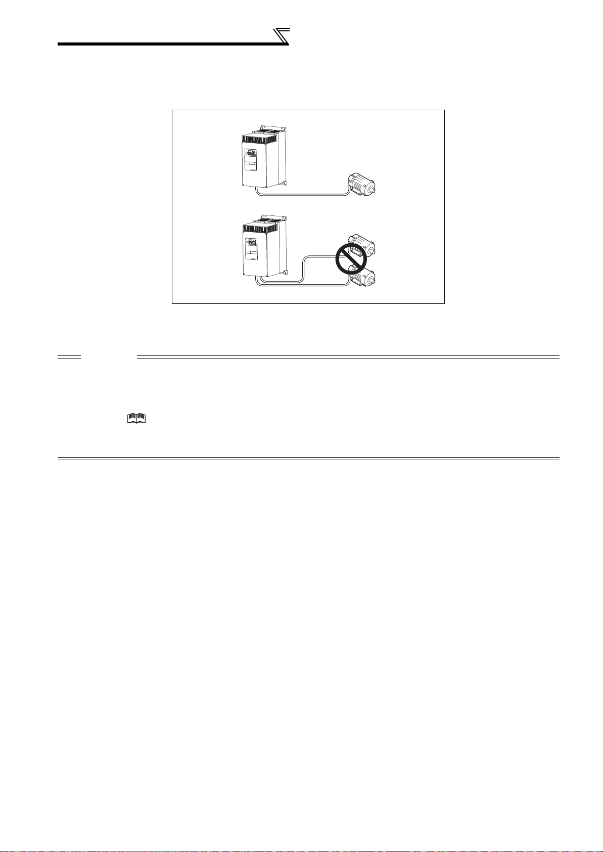
(3) Total wiring length
The overall wiring length for the connection to a single motor or multiple motors should be within 500m (with unshielded
wires).
(The wiring length should be within 100m for the operation under vector control or when using shielded wires.)
Total wiring length
500m or less
300m
300m
300m + 300m = 600m
When driving a 400V class motor by the inverter, surge voltages attributable to the wiring constants may occur at
the motor terminals, deteriorating the insulation of the motor.
Refer to page 42 for measures against deteriorated insulation.
CAUTION
· Especially with the long-distance wiring and the wiring with shielded wires, the inverter may be affected by a charging current
caused by the stray capacitance from the wiring, leading to a malfunction of the overcurrent protective function or the fast response
current limit function, or an inverter fault. It may also lead to a malfunction or fault of the equipment connected on the inverter output
side. Stray capacitance from the wiring varies with its wiring conditions. The overall wiring length specified above is only a reference
value. If the fast-response current limit function malfunctions, disable this function. (For Pr. 156 Stall prevention operation selection, refer
to Chapter 4 of the Instruction Manual (Applied).)
· For explanation of the surge voltage suppression filter (FR-ASF-H/FR-BMF-H) and sine wave filter (MT-BSL/BSC), refer to the
manual of each option.
· Do not connect a surge voltage suppression filter (FR-ASF-H/FR-BMF-H) during the operation under vector control.
(4) Cable size of the control circuit power supply (terminal R1/L11, S1/L21)
· Terminal screw size: M4
· Cable size: 0.75mm
· Tightening torque: 1.5N·m
2
to 2mm
2
18
Page 26
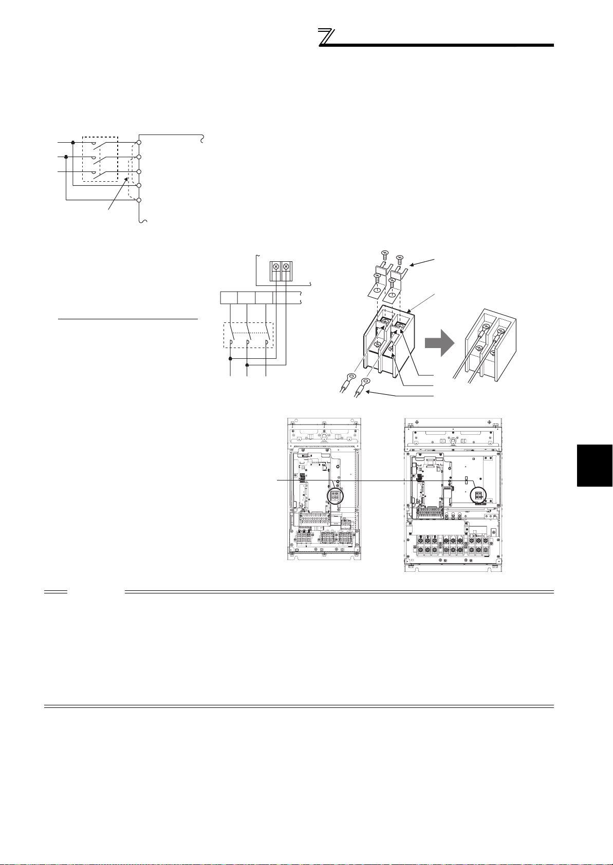
Main circuit terminal specifications
2.2.4 When connecting the control circuit and the main circuit separately to the power supply
<Connection diagram> When fault occurs, opening of the electromagnetic contactor (MC) on the
MC
Remove the jumper
R/L1
S/L2
T/L3
R1/L11
S1/L21
Inverter
inverter power supply side results in power loss in the control circuit,
disabling the fault output signal retention. Terminals R1/L11 and S1/L21 are
provided to hold a fault signal. In this case, connect the power supply
terminals R1/L11 and S1/L21 of the control circuit to the input side of the MC.
Do not connect the power cable to incorrect terminals. Doing so may
damage the inverter.
1)Remove the upper screws.
2)Remove the lower screws.
3)Pull the jumper toward you to
remove.
Connect the separate power supply
4)
cable for the control circuit to the
upper terminals (R1/L11, S1/L21).
R1/
L11
T/L3
S/L2
R/L1
MC
Main power supply
Power supply
terminal block for
the control circuit
S1/
L21
Power supply
terminal block
for the control circuit
FR-A721-5.5K to 15K
FR-A741-5.5K to 15K
3)
Power supply terminal block
for the control circuit
R1/L11
1)
2)
4)
FR-A721-18.5K to 55K
FR-A741-18.5K to 55K
S1/L21
2
CAUTION
· Do not turn off the control power (terminals R1/L11 and S1/L21) with the main circuit power (R/L1, S/L2, T/L3) on. Doing so may
damage the inverter. Make up a circuit which will switch off the main circuit power supply terminals R/L1, S/L2, T/L3 when the
control circuit power supply terminals R1/L11, S1/L21 are switched off.
· Be sure to use the inverter with the jumpers across terminals R/L1 and R1/L11 and across terminals S/L2 and S1/L21 removed
when supplying power from other sources. The inverter may be damaged if you do not remove the jumper.
· The voltage should be the same as that of the main control circuit when the control circuit power is supplied from other than the
input side of the MC.
· When separate power is supplied from R1/L11 and S1/L21, the power capacity necessary for the 15K or lower is 90VA, for the
18.5K or higher is 100VA.
· If the main circuit power is switched OFF (for 0.1s or more) then ON again, the inverter resets and a fault output will not be held.
WIRING
19
Page 27
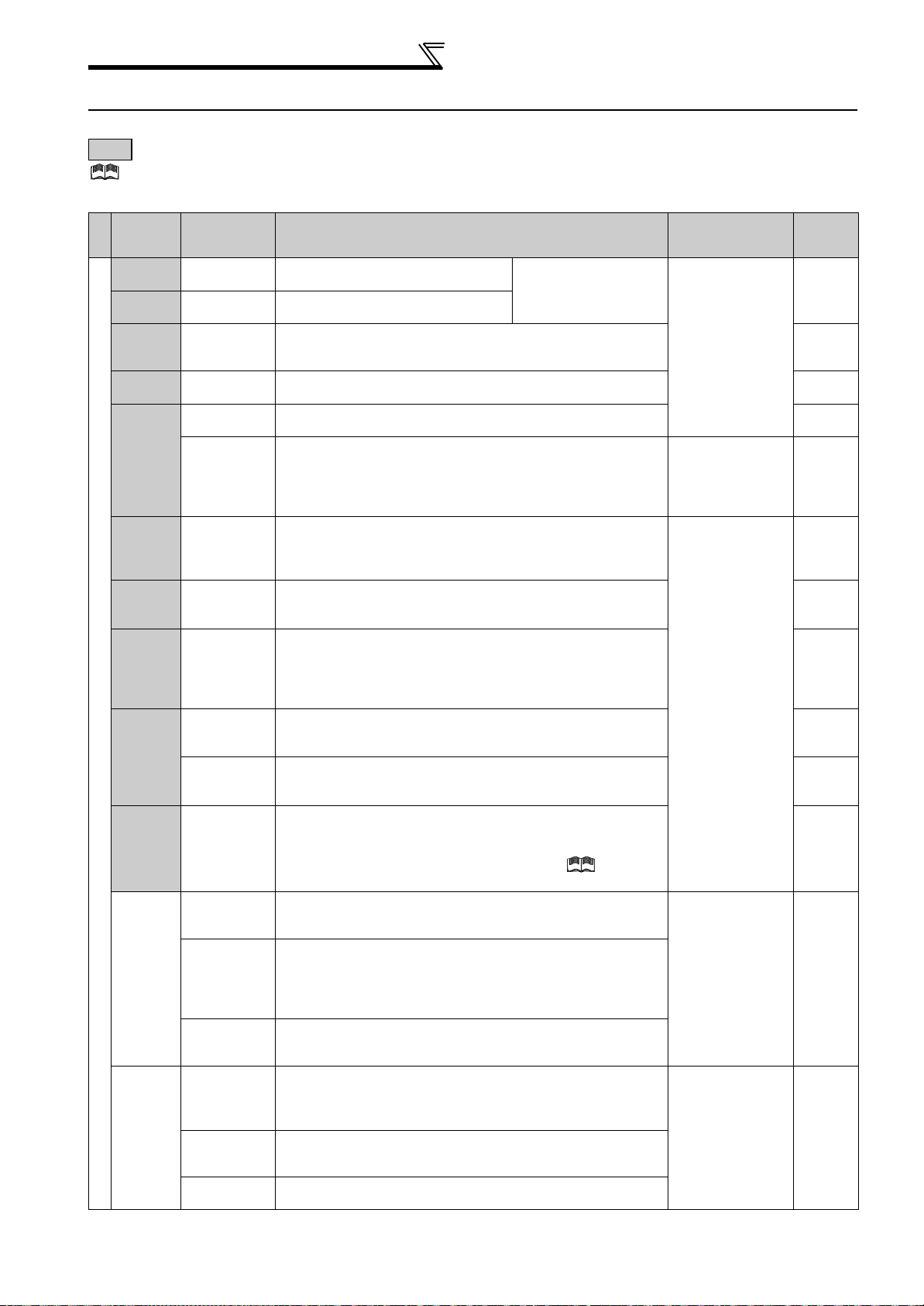
Control circuit specifications
2.3 Control circuit specifications
2.3.1 Control circuit terminals
indicates that terminal functions can be selected using Pr. 178 to Pr. 196 (I/O terminal function selection) (Refer to Chapter 4 of
the Instruction Manual (Applied).)
(1) Input signals
Terminal
Symbol
Type
STF
STR
STOP
RH,
RM, RL
JOG
RT
MRS Output stop
RES Reset
AU
Contact input
CS
SD
PC
Ter minal
Name
Forward
rotation start
Reverse
rotation start
Start selfholding
selection
Multi-speed
selection
Jog mode
selection
Pulse train
input
Second
function
selection
Terminal 4
input
selection
PTC input
Selection of
automatic
restart after
instantaneous
power failure
Contact input
common (sink)
(initial setting)
External
transistor
common
(source)
24VDC power
supply
common
External
transistor
common (sink)
(initial setting)
Contact input
common
(source)
24VDC power
supply
Description
Turn ON the STF signal to start forward
rotation and turn it OFF to stop.
Turn ON the STR signal to start reverse
rotation and turn it OFF to stop.
Turn ON the STOP signal to self-hold the start signal. *2
Multi-speed can be selected according to the combination of RH,
RM and RL signals.
Turn ON the JOG signal to select Jog operation (initial setting)
and turn ON the start signal (STF or STR) to start Jog operation.
JOG terminal can be used as pulse train input terminal. To use as
pulse train input terminal, the Pr. 291 setting needs to be changed.
k
(maximum input pulse: 100
Turn ON the RT signal to select second function.
When the second function such as "second torque boost" and
"second V/F (base frequency)" are set, turning on the RT signal
selects these functions.
Turn ON the MRS signal (20ms or more) to stop the inverter output.
Use to shut off the inverter output when stopping the motor by
electromagnetic brake.
Used to reset fault output provided when fault occurs.
Turn ON the RES signal for more than 0.1s, then turn it OFF.
Initial setting is for reset always. By setting Pr. 75, reset can be set
to enabled only at fault occurrence. Recover about 1s after reset
is cancelled.
Terminal 4 is valid only when the AU signal is turned ON. (The
frequency setting signal can be set between 4 and 20mADC.)
Turning the AU signal ON makes terminal 2 (voltage input) invalid.
AU terminal is used as PTC input terminal (thermal protection of
the motor). When using it as PTC input terminal, set the AU/PTC
switch to PTC.
When the CS signal is left ON, the inverter restarts automatically
at power restoration. Note that restart setting is necessary for this
operation. In the initial setting, a restart is disabled.
(Refer to Pr. 57 Restart coasting time in Chapter 4 of
Instruction Manual (Applied).)
Common terminal for contact input terminal (sink logic) and terminal
FM.
When connecting the transistor output (open collector output),
such as a programmable controller, when source logic is
selected, connect the external power supply common for
transistor output to this terminal to prevent a malfunction caused
by undesirable currents.
Common output terminal for 24VDC 0.1A power supply (PC
terminal).
Isolated from terminals 5 and SE.
When connecting the transistor output (open collector output), such
as a programmable controller, when sink logic is selected, connect
the external power supply common for transistor output to this
terminal to prevent a malfunction caused by undesirable currents.
Common terminal for contact input terminal (source logic).
Can be used as 24VDC 0.1A power supply.
pulses/s)
When the STF and STR
signals are turned ON
simultaneously, the stop
command is given.
the
Rated
Specifications
Input resistance
4.7kΩ
Voltage at opening:
21 to 27VDC
Contacts at shortcircuited: 4 to
6mADC
Input resistance
2kΩ
Contacts at shortcircuited: 8 to
13mADC
Input resistance
4.7kΩ
Voltage at opening:
21 to 27VDC
Contacts at shortcircuited: 4 to
6mADC
--------------- ----- —
Power supply
voltage range 19.2
to 28.8VDC
Permissible load
current 100mA
Refer to
page
92
94
*2
*2
*2
*2
141
98
*2
*2
24
20
Page 28
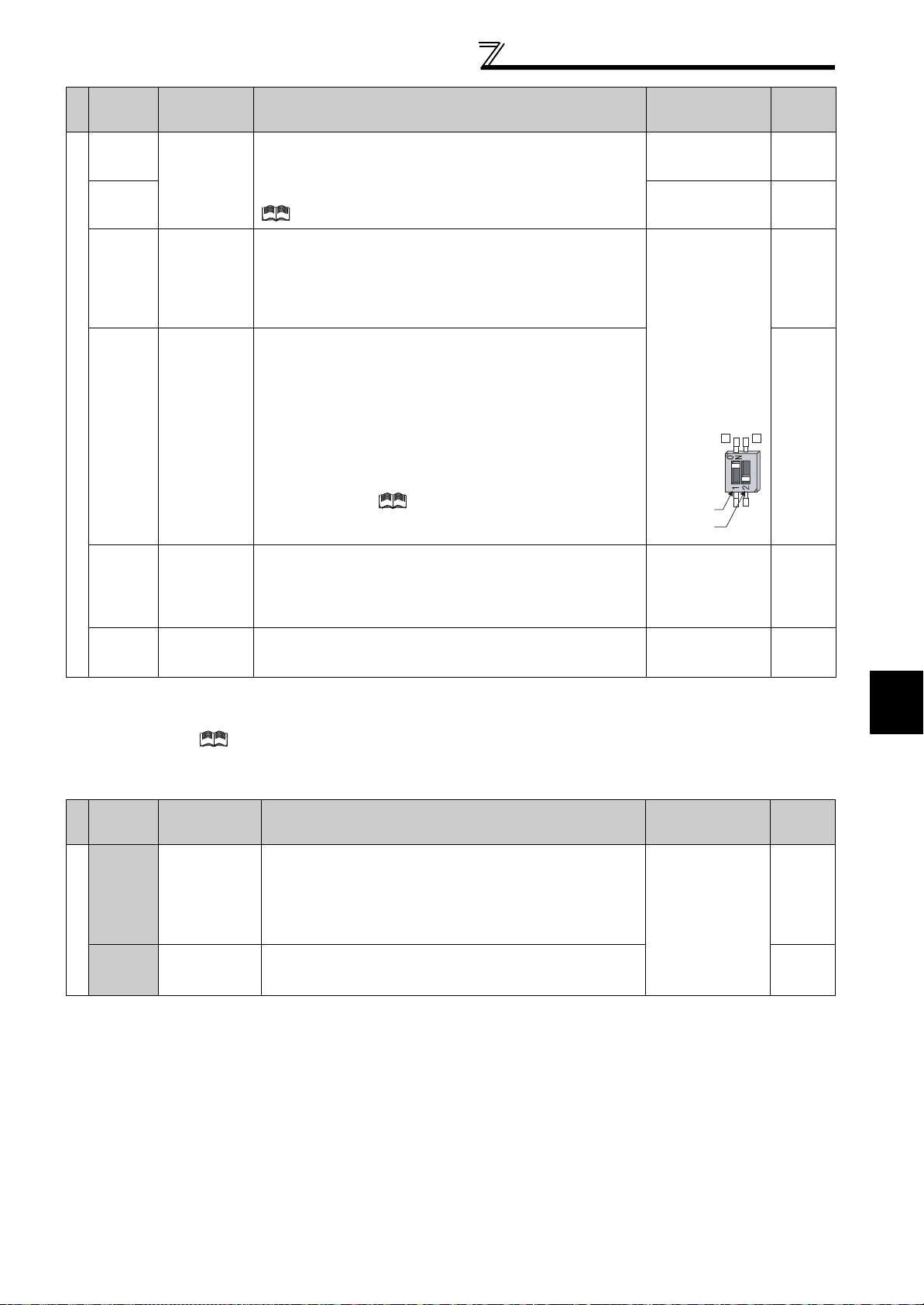
Control circuit specifications
Terminal
Symbol
Typ e
10E
10
2
4
Frequency setting
1
5
*1 Set Pr. 73, Pr. 267, and a voltage/current input switch correctly, then input an analog signal in accordance with the setting.
Applying a voltage signal with voltage/current input switch ON (current input is selected) or a current signal with switch OFF (voltage input is
selected) could cause component damage of the inverter or analog circuit of signal output devices.
*2 Refer to Chapter 4 of
Terminal
Name
Frequency
setting power
supply
Frequency
setting
(voltage)
Frequency
setting
(current)
Frequency
setting
auxiliary
Frequency
setting
common
the Instruction Manual (Applied).
Description
When connecting the frequency setting potentiometer at an initial
status, connect it to terminal 10.
Change the input specifications of terminal 2 when connecting it
to terminal 10E. (Refer to Pr. 73 Analog input selection in Chapter 4 of
the Instruction Manual (Applied).)
Inputting 0 to 5VDC (or 0 to 10V, 0 to 20mA) provides the
maximum output frequency at 5V (10V, 20mA) and makes input
and output proportional. Use Pr. 73 to switch from among input 0
to 5VDC (initial setting), 0 to 10VDC, and 0 to 20mA.
Set the voltage/current input switch in the ON position to select
current input (0 to 20mA).
Inputting 4 to 20mADC (or 0 to 5V, 0 to 10V) provides the
maximum output frequency at 20mA makes input and output
proportional. This input signal is valid only when the AU signal is
ON (terminal 2 input is invalid).
Use Pr. 267 to switch from among input 4 to 20mA (initial setting),
0 to 5VDC, and 0 to 10VDC.
Set the voltage/current input switch in the OFF position to select
voltage input (0 to 5V/0 to 10V).
(Refer to Chapter 4 of the Instruction Manual (Applied).) Use Pr.
858 to switch terminal functions.
Inputting 0 to ±5 VDC or 0 to ±10VDC adds this signal to terminal
2 or 4 frequency setting signal. Use Pr. 73 to switch between the
input 0 to ±5VDC and 0 to ±10VDC (initial setting).
Use Pr. 868 to switch terminal functions.
Common terminal for frequency setting signal (terminal 2, 1 or 4)
and analog output terminal AM. Do not earth (ground).
*1
*1
Rated
Specifications
10VDC
Permissible load
current 10mA
5VDC
Permissible load
current 10mA
Voltage input:
Input resistance
10kΩ ± 1kΩ
Maximum
permissible voltage
20VDC
Current input:
Input resistance
245Ω ± 5Ω
Maximum
permissible current
30mA
Voltage/current
input switch
switch1
switch2
Input resistance
10kΩ ± 1kΩ
Maximum
permissible voltage
± 20VDC
4
------------- ------- ------
2
Refer to
page
*2
88, 96
88, 96
90, 98
*2
2
(2) Output signals
Terminal
Symbol
Type
A1,
B1,
C1
Relay
A2,
B2,
C2
Terminal
Name
Relay output 1
(alarm output)
Relay output 2 1 changeover contact output *2
Description
1 changeover contact output indicates that the inverter
protective function has activated and the output stopped.
Fault: No conduction between B and C (conduction between A
and C)
Normal: Conduction between B and C (No conduction between
A and C)
Rated
Specifications
Contact capacity:
230VAC 0.3A
(Power factor=0.4)
30VDC 0.3A
Refer to
page
*2
WIRING
21
Page 29

Control circuit specifications
Terminal
Symbol
Typ e
RUN
SU
OL
Open collector
IPF
FU
SE
FM
Pulse
AM
Analog
Terminal
Name
Inverter
running
Up to
frequency
Overload
warning
Instantaneous
power failure
Frequency
detection
Open collector
output common
For meter
NPN open
collector output
Analog signal
output
Description
Rated
Specifications
Refer to
page
Switched low when the inverter output frequency is equal to or
higher than the starting frequency (initial value 0.5Hz). Switched
high during stop or DC injection brake operation.
Switched low when the output
frequency reaches within the range of
±10% (initial value) of the set frequency.
Switched high during acceleration/
deceleration and at a stop. *1
Switched low when stall prevention is
activated by the stall prevention
function. Switched high when stall
prevention is cancelled.
*1
Switched low when an instantaneous
power failure and under voltage
protections are activated.
*1
Switched low when the inverter output
frequency is equal to or higher than the
*1
Alarm code (4bit)
output
Permissible load
24VDC (27VDC
maximum) 0.1A
(A voltage drop is
2.8V maximum
when the signal is
on.)
*1 Low is when the
open collector
output transistor is
ON (conducts).
High is when the
transistor is OFF
(does not
conduct).
preset detected frequency and high
when less than the preset detected
frequency.
*1
C o m m o n t e r m i n a l f o r t e r m i n a l s R U N , S U , O L , I P F, F U -------------------- -----
Permissible load
current 2mA
1440pulses/s at
60Hz
Maximum output
pulse: 50kpulses/s
Permissible load
current : 80mA
Output signal 0 to
10VDC
Permissible load
current 1mA
(load impedance
Select one e.g. output frequency from
monitor items. Not output during
inverter reset.
The output signal is proportional to the
magnitude of the corresponding
monitoring item.
To set a full-scale value for monitoring
the output frequency and the output
current, set Pr. 56 and Pr.158.
*2
Output item:
Output frequency
(initial setting)
Signals can be output
from the open
collector terminals by
setting Pr. 291.
Output item:
Output frequency
(initial setting)
10kΩ or more)
Resolution 8 bit
*2
*2
*2
*2
*2
*2
*2
*2
*2 Refer to Chapter 4 of the Instruction Manual (Applied).
(3) Communication
Type
RS-485
USB
Terminal
Symbol
--------------- -----
TXD+
TXD-
RXD+
RXD-
RS-485 terminals
SG
--------------- -----
Terminal
Name
PU
connector
Inverter
transmission
terminal
Inverter
reception
terminal
Earth (Ground)
USB
connector
With the PU connector, communication can be made through RS-485.
(for connection on a 1:1 basis only)
. Conforming standard : EIA-485 (RS-485)
. Transmission format : Multidrop link
. Communication speed : 4800 to 38400bps
. Overall length : 500m
With the RS-485 terminals, communication can be made through RS-485.
Conforming standard : EIA-485 (RS-485)
Transmission format : Multidrop link
Communication speed : 300 to 38400bps
Overall length : 500m
The FR Configurator can be used by connecting the inverter to the personal
computer through USB.
Interface:Conforms to USB1.1
Transmission speed:12Mbps
Connector:USB B connector (B receptacle)
Description
Refer to
page
26
26
27
22
Page 30
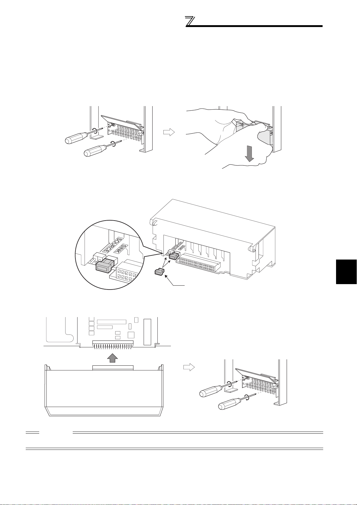
Control circuit specifications
2.3.2 Changing the control logic
The input signals are set to sink logic (SINK) when shipped from the factory.
To change the control logic, the jumper connector on the back of the control circuit terminal block must be moved to the
other position.
(The output signals may be used in either the sink or source logic independently of the jumper connector position.)
1) Loosen the two installation screws in both ends of the control circuit terminal block. (These screws cannot be
removed.)
Pull down the terminal block from behind the control circuit terminals.
2) Change the jumper connector set to the sink logic (SINK) on the rear panel of the control circuit terminal block to
source logic (SOURCE).
Jumper connector
3) Using care not to bend the pins of the inverter's control circuit connector, reinstall the control circuit terminal block
and fix it with the mounting screws.
CAUTION
1. Make sure that the control circuit connector is fitted correctly.
2. While power is ON, never disconnect the control circuit terminal block.
2
WIRING
23
Page 31

Control circuit specifications
r
4)Sink logic and source logic
⋅ In sink logic, a signal switches ON when a current flows from the corresponding signal input terminal.
Terminal SD is common to the contact input signals. Terminal SE is common to the open collector output signals.
⋅ In source logic, a signal switches ON when a current flows into the corresponding signal input terminal.
Terminal PC is common to the contact input signals. Terminal SE is common to the open collector output signals.
Current flow concerning the input/output signal
when sink logic is selected
Sink logic
Current
STF
STR
SD
Inverter
RUN
SE
R
R
TB1
-
+
TB17
24VDC
Current flow
DC input (sink type)
<Example: QX40>
R
R
Sink
connector
Current flow concerning the input/output signal
when source logic is selected
Source logic
PC
Current
STF
R
STR
R
Inverter
RUN
SE
+
24VDC
Current flow
DC input (source type)
<Example: QX80>
TB1
R
-
TB18
Source
connecto
R
• When using an external power supply for transistor output
⋅ Sink logic type
Use terminal PC as a common terminal, and perform
wiring as shown below. (Do not connect terminal SD of
the inverter with terminal 0V of the external power
supply. When using terminals PC and SD as a 24VDC
power supply, do not install a power supply in parallel in
the outside of the inverter. Doing so may cause a
malfunction due to undesirable currents.)
QY40P type transistor
output unit
Constant
voltage
circuit
TB1
TB2
TB17
TB18
24VDC
STF
STR
Inverter
24VDC
(SD)
PC
SD
Current flow
⋅ Source logic type
Use terminal SD as a common terminal, and perform
wiring as shown below. (Do not connect terminal PC of
the inverter with terminal +24V of the external power
supply. When using terminals PC and SD as a 24VDC
power supply, do not install an external power supply in
parallel with the inverter. Doing so may cause a
malfunction in the inverter due to undesirable currents.)
PC
STF
STR
24VDC
SD
Inverter
24VDC
(SD)
QY80 type transistor
output unit
Constant
voltage
circuit
Fuse
TB1
TB2
TB17
TB18
Current flow
24
Page 32

2.3.3 Control circuit terminal layout
Terminal screw size: M3.5
Tightening torque: 1.2N·m
Control circuit specifications
A1 B1 C1 A2 B2 C2 10E 10 2 5 4
AURTRHRMRL
FM
MRS
STOP
1AMSDRES
PCCSJOGSTRSTFSDSDFUOLIPFSURUNSE
(1) Common terminals of the control circuit (SD, 5, SE)
Terminals SD, 5, and SE are all common terminals (0V) for I/O signals and are isolated from each other. Do not earth
(ground) these terminals.
Avoid connecting the terminal SD and 5 and the terminal SE and 5.
Terminal SD is a common terminal for the contact input terminals (STF, STR, STOP, RH, RM, RL, JOG, RT, MRS, RES,
AU, CS) and frequency output signal (FM).
The open collector circuit is isolated from the internal control circuit by photocoupler.
Terminal 5 is a common terminal for frequency setting signal (terminal 2, 1 or 4) and analog output terminal AM.
It should be protected from external noise using a shielded or twisted cable.
Terminal SE is a common terminal for the open collector output terminal (RUN, SU, OL, IPF, FU).
The contact input circuit is isolated from the internal control circuit by photocoupler.
(2) Signal inputs by contactless switches
The contacted input terminals of the inverter (STF, STR, STOP, RH,
RM, RL, JOG, RT, MRS, RES, AU, CS) can be controlled using a
transistor instead of a contacted switch as shown on the right.
STF, etc
+24V
Inverter
SD
External signal input using transistor
2.3.4 Wiring instructions
1) It is recommended to use the cables of 0.75mm2 gauge for connection to the control circuit terminals.
If the cable gauge used is 1.25mm
the cables are run improperly, resulting in an operation panel contact fault.
2) The wiring length should be 30m(200m for terminal FM) maximum.
3) Use two or more parallel micro-signal contacts or twin contacts to
prevent a contact faults when using contact inputs since the
control circuit input signals are micro-currents.
4) Use shielded or twisted cables for connection to the control circuit terminals and run them away from the main and
power circuits (including the 200V relay sequence circuit).
5) Do not apply a voltage to the contact input terminals (e.g. STF) of the control circuit.
6) Always apply a voltage to the fault output terminals (A, B, C) via a relay coil, lamp, etc.
2
or more, the front cover may be lifted when there are many cables running or
Micro signal contacts Twin contacts
2
WIRING
25
Page 33

Control circuit specifications
2.3.5 When connecting the operation panel using a connection cable
Having an operation panel on the enclosure surface is convenient. With a connection cable, you can mount the
operation panel (FR-DU07) to the enclosure surface, and connect it to the inverter.
Parameter unit connection cable
(FR-CB2)(option)
Operation panel(FR-DU07)
Operation panel connection connector
(FR-ADP)(option)
CAUTION
Do not connect the PU connector to the computer's LAN port, FAX modem socket or telephone connector.
The inverter and machine could be damaged due to differences in electrical specifications.
REMARKS
⋅ Refer to page 4 for removal method of the operation panel.
· Overall wiring length when the operation panel is connected: 20m maximum
· Refer to the following when fabricating the cable on the user side.
Commercially available product examples (as of January 2010)
Product Type Manufacturer
1) Communication cable
2) RJ-45 connector 5-554720-3 Tyco Electronics
⋅ The inverter can be connected to the computer and FR-PU04/FR-PU07.
SGLPEV-T (Cat5e/300m)
24AWG × 4P
Mitsubishi Cable Industries, Ltd.
2.3.6 RS-485 terminal block
⋅ Conforming standard: EIA-485(RS-485)
⋅ Transmission format: Multidrop link
⋅ Communication speed: MAX 38400bps
⋅ Overall length: 500m
⋅ Connection cable:Twisted pair cable
(4 pairs)
OPEN
100Ω
Terminating resistor switch
Factory-set to "OPEN".
Set only the terminating resistor switch of the
remotest inverter to the "100Ω" position.
26
TXD
RDA1
RDB1
(RXD1+)
(RXD1-)
SDA1
(TXD1+)
(TXD1-)
P5S
(VCC)SG(GND)
RDA2
(RXD2+)
SDB1
SDA2
(TXD2+)
P5S
(VCC)SG(GND)
RDB2
(RXD2-)
SDB2
(TXD2-)
RXD
VCC
Page 34

2.3.7 Communication operation
Using the PU connector or RS-485 terminal, you can
perform communication operation from a personal
computer etc. When the PU connector is connected
with a personal, FA or other computer by a
communication cable, a user program can run and
monitor the inverter or read and write to parameters.
For the Mitsubishi inverter protocol (computer link
operation), communication can be performed with the
PU connector and RS-485 terminal.
For the Modbus-RTU protocol, communication can
be performed with the RS-485 terminal.
For further details, refer to Chapter 4 of the
Instruction Manual (Applied).
Programmable controller
Inverter Inverter Inverter
2.3.8 USB connector
A personal computer and an inverter can be connected with a USB (Ver1. 1) cable.
You can perform parameter setting and monitoring with the FR Configurator.
•USB communication specifications
Control circuit specifications
Multidrop link
(32 inverters maximum
are connectable)
Interface
Transmission speed
Wiring length Maximum 5m
Connector
Power supply
Removal of cover
Place a flat-blade screwdriver,
etc. in a slot and push up the
cover to open.
Conforms to USB1.1
12Mbps
USB B connector (B receptacle)
Self-power supply
USB cable
USB connector
2
WIRING
27
Page 35

Connection of motor with encoder (vector control)
2.4 Connection of motor with encoder (vector control)
Orientation control and encoder feedback control, and speed control, torque control and position control by full-scale
vector control operation can be performed using a motor with encoder and a plug-in option FR-A7AP.
(1) Structure of the FR-A7AP
LED1
LED2
LED3
Mounting
hole
Terminal
block
SW1
Front view Rear view
4
SW2
3
2
N
1
O
SW3
2
N
1
O
FR-A7AP
Mounting
hole
Terminating resistor selection
switch (SW2)
Switch ON/OFF of the internal
terminating resistor.
(Refer to page 29.)
CON2 connector
Not used.
Encoder specification selection switch (SW1)
Used to change the specification of encoder
(differential line driver/complementary).
Switch for manufacturer
setting (SW3)
Do not change from initiallyset status (1, 2:OFF ).
2
N
1
O
Connector
Connect to the inverter
option connector.
Terminal layout
PA2
PB2
PZ2
SD
SD
PO
PIN and PO are
not used.
(Refer to page 29.)
(2) Terminals of the FR-A7AP
Terminal Terminal Name Description
PA1
Encoder A-phase signal input terminal
PA2 Encoder A-phase inverse signal input terminal
PB1
PB2
Encoder B-phase signal input terminal
Encoder B-phase inverse signal input terminal
A-, B- and Z-phase signals are input from the encoder.
PZ1 Encoder Z-phase signal input terminal
PZ2
PG
SD
PIN
PO
Encoder Z-phase inversion signal input terminal
Encoder power supply (positive side) input terminal
Encoder power supply ground terminal
Not used.
Input terminal for the encoder power supply.
Connect the external power supply (5V, 12V, 15V, 24V) and the
encoder power cable.
Mounting
hole
PA1
PB1
PZ1
PG
PG
PIN
28
Page 36

(3) Switches of the FR-A7AP
• Encoder specification selection switch (SW1)
Select either differential line driver or complementary
It is initially set to the differential line driver. Switch its position according
to output circuit.
Connection of motor with encoder (vector control)
4
2
SW2
N
3
1
O
2
Differential line
driver (initial status)
Complementary
N
SW3
1
O
FR-A7AP
SW1
• Terminating resistor selection switch (SW2)
Select ON/OFF of the internal terminating resistor. Set the switch to ON
(initial status) when an encoder output type is differential line driver and
Internal terminating
resistor-ON
(initial status)
4
2
SW2
N
3
1
O
2
N
SW3
1
O
set to OFF when complementary.
ON : with internal terminating resistor (initial status)
SW1
OFF : without internal terminating resistor
REMARKS
· Set all switches to the same setting (ON/OFF).
· If the encoder output type is differential line driver, set the terminating resistor
switch to the "OFF" position when sharing the same encoder with other unit (NC
(numerical controller), etc.) or a terminating resistor is connected to other unit.
Internal terminating resistor-OFF
• Motor used and switch setting
Motor
Mitsubishi standard motor with encoder
Mitsubishi high efficiency motor with
encoder
Mitsubishi constant-torque motor with
encoder
SF-JR Differential ON 5V
SF-HR Differential ON 5V
Others
SF-JRCA Differential ON 5V
SF-HRCA Differential ON 5V
Others
Encoder Specification
Selection Switch (SW1)
*1 *1 *1
*1 *1 *1
Vector control dedicated motor SF-V5RU Complimentary OFF 12V
Other manufacturer motor with encoder –
*1 *1 *1
*1 Set according to the motor (encoder) used.
*2 Choose a power supply (5V/12V/15V/24V) for encoder according to the encoder used.
Terminating Resistor
Selection Switch (SW2)
Power
Specifications
FR-A7AP
*2
2
CAUTION
SW3 switch is for manufacturer setting. Do not change the setting.
• Encoder specification
Item Encoder for SF-JR/HR/JRCA/HRCA Encoder for SF-V5RU
Resolution 1024 Pulse/Rev 2048 Pulse/Rev
Power supply
voltage
Current
consumption
Output signal form
5VDC±10% 12VDC±10%
150mA 150mA
A, B phases (90° phase shift)
Z phase: 1 pulse/rev
A, B phases (90° phase shift)
Z phase: 1 pulse/rev
Output circuit Differential line driver 74LS113 equivalent Complimentary
Output voltage
H level: 2.4V or more
L level: 0.5V or less
H level: "Power supply for encoder-3V" or more
L level: 3V or less
CAUTION
Encoder with resolution of 1000 to 4096 pulse/rev is recommended.
WIRING
29
Page 37

Connection of motor with encoder (vector control)
Wh
ithout i
(4) Encoder Cable
SF-JR/HR/JRCA/HRCA Motor with Encoder SF-V5RU, SF-THY
Earth cable
*
60mm
FR-A701
(FR-A7AP)
PA1
PA2
PB1
PB2
PZ1
PZ2
PG
SD
F-DPEVSB 12P 0.2mm
Approx. 140mm
L
Type Length L (m)
FR-JCBL5 5
FR-JCBL15 15
FR-JCBL30 30
Encoder
C
R
A
N
B
P
H
K
2
2mm
2
MS3057-12A
MS3106B20-29S
Positioning keyway
A
B
M
C
N
L
T
K
S
J
MS3106B20-29S
(As viewed from wiring side)
D
P
E
R
F
H
G
Inverter side
Earth cable
60mm
⋅ A P clip for earthing (grounding) a
shielded cable is provided.
FR-A701
(FR-A7AP)
F-DPEVSB 12P 0.2mm
11m m
PA1
PA2
PB1
PB2
PZ1
PZ2
PG
SD
2mm
2
Encoder side
connector
2
L
Type Length L (m)
FR-V7CBL5 5
FR-V7CBL15 15
FR-V7CBL30 30
Encoder
A
B
C
D
F
G
S
R
MS3057-12A
MS3106B20-29S
Positioning keyway
A
M
B
N
L
K
(As viewed from wiring side)
C
D
P
T
S
J
MS3106B20-29S
E
R
F
H
G
* As the terminal block of FR-A7AP is an insertion type, earthing cables need to be modified. (See below)
• When using the dedicated encoder cable (FR-JCBL, FR-V5CBL, etc.) for the conventional motor, cut the crimpling
terminal of the encoder cable and strip its sheath to make its cables loose.
Also, protect the shielded cable of the twisted pair
Wire stripping size
shielded cable to ensure that it will not make contact with
the conductive area.
Wire the stripped wire after twisting it to prevent it from
becoming loose. In addition, do not solder it.
5mm
Use a blade terminal as necessary.
REMARKS
Information on blade terminals
Commercially available product examples (as of January 2010)
zPhoenix Contact Co.,Ltd.
Terminal Screw
Size
Wire Size (mm2)
with insulation sleeve without insulation sleeve
M2 0.3, 0.5 AI 0,5-6WH A 0,5-6
Blade Terminal Model
Blade terminal
crimping tool
CRIMPFOX 6
zNICHIFU Co.,Ltd.
Terminal Screw
Size
M2
Wire Size (mm2)
0.3 to 0.75 BT 0.75-7 VC 0.75 NH 67
en using the blade terminal (w
Blade terminal product
number
nsulation sleeve),
Insulation product
number
Blade terminal
crimping tool
use care so that the twisted wires do not come out.
30
Page 38

Connection of motor with encoder (vector control)
Connection terminal compatibility table
Motor SF-V5RU, SF-THY SF-JR/HR/JRCA/HRCA (with Encoder)
Encoder cable FR-V7CBL FR-JCBL
PA1 PA PA
PA2 Keep this open. PAR
PB1 PB PB
FR-A7AP terminal
(5) Wiring
• Speed control
Standard motor with encoder (SF-JR), 5V differential line driver
PB2 Keep this open. PBR
PZ1 PZ PZ
PZ2 Keep this open. PZR
PG PG 5E
SD SD AG2
Vector control dedicated motor
(SF-V5RU, SF-THY),
12V complementary
Three-phase
AC power supply
Forward rotation start
Reverse rotation start
Contact input common
Frequency command
Frequency setting
potentiometer
1/2W1k
Torque limit
command
( 10V)
(+)
(-)
• Torque control
Standard motor with encoder (SF-JR), 5V differential line driver
Three-phase
AC power supply
Forward rotation start
Reverse rotation start
Contact input common
Speed limit command
Frequency setting
potentiometer
1/2W1k
Torque command
( 10V)
SF-JR motor
MCCB
R/L1
S/L2
T/L3
Inverter
U
V
W
with encoder
U
V
W
Three-phase
AC power
IM
E
STF
FR-A7AP
STR
SD
PA1
PA2
PB1
PB2
10
2
5
1
Differential
PZ1
PZ2
Complementary
Terminating
resistor ON
OFF
*4
PG
SD
PG
SD
*6
3
2
Ω
1
Earth
(Ground)
*1
C
R
A
N
B
P
H
K
*3
5VDC power supply *5
(-)
(+)
Encoder
*2
*7
supply
MCCB MC
Inverter
External
thermal
relay input
FR-A7AP
Differential
Complementary
Terminating
resistor
ON
OFF
*8
CS(OH)
PA1
PA2
PB1
PB2
PZ1
PZ2
*4
U
V
W
PC
2W1kΩ
SD
PG
SD
PG
SD
*6
SF-V5RU, SF-THY
OCR
A
B
C
U
V
W
E
Earth
Thermal relay
(Ground)
protector
G1
G2
*1
A
B
C
D
F
G
S
R
*3
12VDC power supply *5
(-)
(+)
FAN
IM
Encoder
*2
2
Vector control dedicated motor
(SF-V5RU, SF-THY),
WIRING
12V complementary
(+)
(-)
MCCB
R/L1
S/L2
T/L3
Inverter
U
V
W
SF-JR motor
with encoder
U
V
W
Three-phase
AC power
IM
E
STF
FR-A7AP
STR
SD
PA1
PA2
PB1
PB2
10
2
5
1
Differential
PZ1
PZ2
Complementary
Terminating
resistor ON
OFF
*4
PG
PG
SD
SD
*6
3
2
Ω
1
Earth
(Ground)
*3
(+)
*1
C
R
A
N
B
P
H
K
5VDC
(-)
power supply
Encoder
*2
*5
*7
supply
MCCB MC
Inverter
External
thermal
relay input
FR-A7AP
Differential
Complementary
Terminating
resistor
ON
OFF
*8
CS(OH)
PA1
PA2
PB1
PB2
PZ1
PZ2
*4
U
V
W
PC
2W1kΩ
SD
PG
SD
PG
SD
*6
SF-V5RU, SF-THY
OCR
A
B
C
U
V
W
E
Earth
Thermal relay
(Ground)
protector
G1
G2
*1
A
B
C
D
F
G
S
R
*3
12VDC power supply *5
(-)
(+)
FAN
IM
Encoder
*2
31
Page 39

Connection of motor with encoder (vector control)
• Position control
Vector control dedicated motor (SF-V5RU, SF-THY), 12V complementary
Positioning unit
MELSEQ-Q QD75P1
FLS
RLS
DOG
STOP
CLEAR
PULSE F
PULSE R
CLEAR COM
PULSE COM
RDY COM
COM
READY
Torque limit command
(
±
10V)
Three-phase AC
Three-phase AC
power supply
Forward stroke end
Reverse stroke end
Pre-excitation/servo on
Clear signal
Pulse train
Sign signal
24VDC power supply
Preparation ready signal
(+)
(-)
power supply
MCCB
MCCB MC
*7
R/L1
Inverter
S/L2
T/L3
External thermal
relay input
STF
FR-A7AP
STR
LX *
9
CLR
*9
JOG
*10
Differential
NP *
9
line driver
PC
SE
Complementary
Terminating
resistor
RDY
*11
5
OFF
1
CS(OH)
*8
ON
*4 *6
PA1
PA1
PA2
PA2
PB1
PB1
PB2
PB2
PZ1
PZ1
PZ2
PZ2
PC
SD
PG
SD
PG
SD
U
V
W
2W1kΩ
SF-V5RU, SF-THY
OCR
A
B
C
U
V
W
E
Earth
(ground)
G1
G2
A
B
C
D
F
G
S
R
*3
12VDC
(-)
(+)
power supply
Thermal
protector
*1
FAN
IM
Encoder
*2
*5
*1 The pin number differs according to the encoder used.
Speed control, torque control, and position control by pulse train input are properly performed without the connection of
the Z-phase.
*2 Connect the encoder so that there is no looseness between the motor and motor shaft. Speed ratio should be 1:1.
*3 Earth (Ground) the shielded cable of the encoder cable to the enclosure with a P clip, etc. (Refer to page 33.)
*4 For the complementary, set the terminating resistor selection switch to off position. (Refer to page 29.)
*5 A separate power supply of 5V/12V/15V/24V is necessary according to the encoder power specification.
*6 For terminal compatibility of the FR-JCBL, FR-V7CBL and FR-A7AP, refer to page 31.
*7 For the fan of the 7.5kW or less dedicated motor, the power supply is single phase. (200V/50Hz, 200 to 230V/60Hz)
*8 Assign OH (external thermal input) signal to the terminal CS. (Set "7" in Pr. 186 )
Connect a 2W1kΩ resistor between the terminal PC and CS (OH). Install the
resistor pushing against the bottom part of the terminal block so as to avoid a
contact with other cables.
CS(OH)
PC
Control circuit
terminal block
Refer to Chapter 4 of the Instruction Manual (Applied) for details of Pr. 186 CS
terminal function selection.
*9 Assign the function using Pr. 178 to Pr. 184, Pr. 187 to Pr. 189 (input terminal function
selection).
Resistor (2W1kΩ)
*10 When position control is selected, terminal JOG function is invalid and the simple position pulse train input terminal
becomes valid.
*11 Assign the function using Pr. 190 to Pr. 194 (output terminal function selection).
32
Page 40

Connection of motor with encoder (vector control)
e
(6) Instructions for encoder cable wiring
• Use twisted pair shield cables (0.2mm2 or larger) to connect the FR-A7AP and position detector. Cables to terminals PG
and SD should be connected in parallel or be larger in size according to the cable length.
To protect the cables from noise, run them away from any source of noise (e.g. the main circuit and power supply voltage).
Wiring Length Parallel Connection Larger-Size Cable
Within 10m At least two cables in parallel
Within 20m At least four cables in parallel
Cable gauge
2
0.2mm
Within 100m * At least six cables in parallel
* When differential line driver is set and a wiring length is 30m or more
The wiring length can be extended to 100m by slightly increasing the power by 5V (approx. 5.5V) using six or more cables with gauge size of 0.2mm
in parallel or a cable with gauge size of 1.25mm2 or more. Note that the voltage applied should be within power supply specifications of encoder.
• To reduce noise of the encoder cable, earth (ground) the encoder
shielded cable to the enclosure (as near as the inverter) with a P clip or
U clip made of metal.
REMARKS
· For details of the optional encoder dedicated cable (FR-JCBL/FR-V7CBL), refer
to page 30.
· The FR-V7CBL is provided with a P clip for earthing (grounding) shielded cable.
(7) Parameter for encoder (Pr. 359, Pr. 369)
Parameter
Number
Name
Initial
Value
Setting
Range
0.4mm2 or larger
2
0.75mm
1.25mm
Earthing (grounding) example using a P clip
or larger
2
or larger
Encoder cable
Shield
P clip
Description
2
0
359
Encoder rotation
direction
1
1
369
Number of encoder
pulses
1024 0 to 4096
The above parameters can be set when the FR-A7AP (option) is mounted.
(8) Motor for vector control and parameter setting
Pr. 9
Motor Name
Mitsubishi standard
motor
Mitsubishi constanttorque motor
Mitsubishi vector
control dedicated
motor
Other manufacturer's
standard motor
SF-JR
SF-HR
Others
SF-JRCA 4P
SF-HRCA
Others
SF-V5RU
(1500r/min series)
SF-V5RU
(except for 1500r/
min series)
SF-THY 0
—
Electronic thermal
O/L relay
Motor rated current
Motor rated current
Motor rated current
Motor rated current
Motor rated current
Motor rated current
0 *3 30 Motor capacity 4 1 2048
0 *3 13 *1 Motor capacity 4 1 2048
*3 33 *1 Motor capacity 4 1 2048
Motor rated current
Other manufacturer's
constant-torque
—
Motor rated current
motor
Values in the bolded frame are initial values.
*1 Offline auto tuning is necessary. (Refer to page 71)
*2 Set this parameter according to the motor (encoder) used.
*3 Use thermal protector input provided with the motor.
Pr. 71
Applied motor
Motor capacity
0 Motor capacity
40 Motor capacity
3 *1 Motor capacity
1 Motor capacity 4 1 1024
50 Motor capacity
13 *1 Motor capacity
3 *1 Motor capacity
13 *1 Motor capacity
CW
Encoder
A
CCW
A
Encoder
Forward rotation is clockwise
rotation when viewed from A.
Forward rotation is counterclockwis
rotation when viewed from A.
Set the number of encoder pulses output.
Set the number of pulses before it is multiplied by 4.
Pr. 80
Pr. 81
Number of motor
poles
Number of motor poles
Number of motor poles
Number of motor poles
Number of motor poles
Number of motor poles
Number of motor poles
Number of motor poles
Pr. 359
Encoder rotation
direction
1 1024
1 1024
*2 *2
1 1024
*2 *2
*2 *2
*2 *2
Pr. 369
Number of
encoder pulses
2
WIRING
♦Parameters referred to♦
• Vector control (speed control, torque control, position control), orientation control, encoder feedback control
Refer to Chapter 4 of the Instruction Manual (Applied).
33
Page 41

Connection of motor with encoder (vector control)
(9) Combination with a vector control dedicated motor
Refer to the table below when using with a vector control dedicated motor.
• Combination with the SF-V5RU
Vol ta ge 200V class 400V class
Rated speed
Base frequency 50Hz
Maximum speed
Motor capacity
3.7kW 112M SF-V5RU3K FR-A721-5.5K — — —
5.5kW 132S SF-V5RU5K FR-A721-7.5K 132S SF-V5RUH5K FR-A741-7.5K
7.5kW 132M SF-V5RU7K FR-A721-11K 132M SF-V5RUH7K FR-A741-11K
11kW 160M SF-V5RU11K FR-A721-15K 160M SF-V5RUH11K FR-A741-15K
15kW 160L SF-V5RU15K FR-A721-18.5K 160L SF-V5RUH15K FR-A741-18.5K
18.5kW 180M SF-V5RU18K FR-A721-22K 180M SF-V5RUH18K FR-A741-22K
22kW 180M SF-V5RU22K FR-A721-30K 180M SF-V5RUH22K FR-A741-30K
30kW 200L
37kW 200L
45kW 200L *2 SF-V5RU45K FR-A721-55K 200L *2 SF-V5RUH45K FR-A741-55K
Motor frame
number
*2 SF-V5RU30K FR-A721-37K 200L *2 SF-V5RUH30K FR-A741-37K
*2 SF-V5RU37K FR-A721-45K 200L *2 SF-V5RUH37K FR-A741-45K
Motor model Inverter model
• Combination with the SF-V5RU1, 3, 4 and SF-THY
SF-V5RU1 (1:2) SF-V5RU3 (1:3) SF-V5RU4 (1:4)
Vol ta ge 200V class
Rated speed
Base
frequency
Maximum
speed
Motor
capacity
3.7kW 132S SF-V5RU3K1 FR-A721-5.5K 132M SF-V5RU3K3 FR-A721-5.5K 160L SF-V5RU3K4 FR-A721-7.5K
5.5kW 132M SF-V5RU5K1 FR-A721-7.5K 160M SF-V5RU5K3 FR-A721-7.5K 180L SF-V5RU5K4 FR-A721-7.5K
7.5kW 160M SF-V5RU7K1 FR-A721-11K 160L SF-V5RU7K3 FR-A721-11K 200L SF-V5RU7K4 FR-A721-11K
11k W 160L
15kW 180M
18.5kW 180L
22kW 200L
30kW 200L*3
37kW 225S
45kW
Models surrounded by black borders and 400V class are developed upon receipt of order.
Motor
frame
number
250MD
*1 The maximum speed is 2400r/min.
*2 80% output in the high-speed range. (The output is reduced when the speed is 2400r/min or more.)
*3 90% output in the high-speed range. (The output is reduced when the speed is 1000r/min or more.)
1000r/min 1000r/min 500r/min
33.33Hz 33.33Hz 16.6Hz
2000r/min 3000r/min 2000r/min
Motor
model
SF-V5RU11K1
SF-V5RU15K1
SF-V5RU18K1
SF-V5RU22K1
SF-V5RU30K1
SF-V5RU37K1
SF-THY FR-A721-55K
Inverter
model
FR-A721-15K 180M
FR-A721
FR-A721-22K 200L
FR-A721-30K 200L
FR-A721-37K 225S*1
FR-A721-45K
-18.5K
Motor
frame
number
180L
250MD
*1 SF-THY FR-A721-45K
250MD
*1 SF-THY FR-A721-55K
1500r/min
3000r/min
Motor
model
SF-V5RU11K3
SF-V5RU15K3
SF-V5RU18K3
SF-V5RU22K3
SF-V5RU30K3
Motor frame
number
Inverter
model
FR-A721-15K 225S
FR-A721
-18.5K
FR-A721-22K
FR-A721-30K
FR-A721-37K
Motor model Inverter model
Motor
frame
number
225S
250MD
280MD
280MD
280MD
280MD
Motor
Inverter
model
SF-V5RU11K4
SF-V5RU15K4
SF-THY FR-A721-22K
SF-THY FR-A721-30K
SF-THY FR-A721-37K
SF-THY FR-A721-45K
SF-THY FR-A721-55K
FR-A721-15K
FR-A721-22K
model
34
Page 42

EMC and leakage currents
3 PRECAUTIONS FOR USE OF THE INVERTER
3.1 EMC and leakage currents
3.1.1 Leakage currents and countermeasures
Capacitances exist between the inverter I/O cables, other cables and earth and in the motor, through which a leakage
current flows. Since its value depends on the static capacitances, carrier frequency, etc., low acoustic noise operation
at the increased carrier frequency of the inverter will increase the leakage current. Therefore, take the following
measures. Select the earth leakage circuit breaker according to its rated sensitivity current, independently of the carrier
frequency setting.
(1) To-earth (ground) leakage currents
Leakage currents may flow not only into the inverter's own line but also into the other lines through the earth (ground)
cable, etc. These leakage currents may operate earth (ground) leakage circuit breakers and earth leakage relays
unnecessarily.
z Suppression technique
⋅ If the carrier frequency setting is high, decrease the Pr. 72 PWM frequency selection setting. Note that motor noise
increases. Selecting Pr. 240 Soft-PWM operation selection makes the sound inoffensive.
⋅ By using earth leakage circuit breakers designed for harmonic and surge suppression in the inverter's own line and
other line, operation can be performed with the carrier frequency kept high (with low noise).
z To-earth (ground) leakage currents
⋅ Take caution as long wiring will increase the leakage current. Decreasing the carrier frequency of the inverter
reduces the leakage current.
⋅ Increasing the motor capacity increases the leakage current. The leakage current of the 400V class is larger than
that of the 200V class.
(2) Line-to-line leakage currents
Harmonics of leakage currents flowing in static capacitances between the inverter output cables may operate the
external thermal relay unnecessarily. When the wiring length is long (50m or more) for the 400V class small-capacity
model (7.5K or lower), the external thermal relay is likely to operate unnecessarily because the ratio of the leakage
current to the rated motor current increases.
z Line-to-line leakage current data example (200V class)
Motor Capacity
(kW)
3.7 12.8 440 630
5.5 19.4 490 680
7.5 25.6 535 725
Rated Motor
Current(A)
Wiring length 50m Wiring length 100m
Leakage Currents(mA)
⋅Motor SF-JR 4P
⋅Carrier frequency: 14.5kHz
⋅Used wire: 2mm
Cabtyre cable
2
, 4cores
3
*The leakage currents of the 400V class are about twice as large.
MCCB MC
Power
supply
z Measures
⋅ Use Pr. 9 Electronic thermal O/L relay.
⋅ If the carrier frequency setting is high, decrease the Pr. 72 PWM frequency selection setting. Note that motor noise
increases. Selecting Pr. 240 Soft-PWM operation selection makes the sound inoffensive. To ensure that the motor is
protected against line-to-line leakage currents, it is recommended to use a temperature sensor to directly detect
motor temperature.
z Installation and selection of moulded case circuit breaker
Install a moulded case circuit breaker (MCCB) on the power receiving side to protect the wiring of the inverter input
side. Select the MCCB according to the inverter input side power factor (which depends on the power supply voltage,
output frequency and load). Especially for a completely electromagnetic MCCB, one of a slightly large capacity must
be selected since its operation characteristic varies with harmonic currents. (Check it in the data of the corresponding
breaker.) As an earth leakage circuit breaker, use the Mitsubishi earth leakage circuit breaker designed for
harmonics and surge suppression.
Inverter
Thermal relay
Line-to-line static
capacitances
Line-to-line leakage currents path
Motor
IM
35
PRECAUTIONS FOR USE OF THE INVERTER
Page 43

EMC and leakage currents
r
(3) Selection of rated sensitivity current of earth leakage circuit breaker
When using the earth leakage circuit breaker with the inverter circuit, select its rated sensitivity current as follows,
independently of the PWM carrier frequency:
⋅ Breaker designed for harmonic and surge suppression
Rated sensitivity current:
IΔn ≥ 10 × (Ig1 + Ign + Igi + Ig2 + Igm)
⋅ Standard breaker
Rated sensitivity current:
IΔn ≥ 10 × {Ig1 + Ign + Igi + 3 × (Ig2 + Igm)}
Example of leakage current of
cable path per 1km during the
commercial power supply operation
when the CV cable is routed in
metal conduit
(200V 60Hz)
120
100
80
60
40
20
0
Leakage currents (mA)
23.5
8142230386080
5.5
Cable size (mm2)
100
150
Leakage current example of
three-phase induction moto
during the commercial
power supply operation
(200V 60Hz)
2. 0
1. 0
0. 7
0. 5
0. 3
0. 2
0. 1
Leakage currents (mA)
1. 5 3.7
7. 5 152211373055
2. 2
Motor capacity (kW)
455.5 18. 5
<Example>
5.5mm
ELB
Ig1 Ign
Noise
filter
2 ×
5m 5.5mm
Inverter
Igi
2 ×
40m
IM
Ig2 Igm
3φ
200V
5.5kW
Leakage current Ig1 (mA) 33 ×
Leakage current Ign (mA) 0 (without noise filter)
Leakage current Igi (mA) 1
Leakage current Ig2 (mA) 33 ×
Motor leakage current Igm (mA) 0.29
Total leakage current (mA) 2.78 6.00
Rated sensitivity current (mA) (≥ Ig × 10) 30 100
Ig1, Ig2: Leakage currents in wire path during commercial
power supply operation
Ign: Leakage current of inverter input side noise filter
Igm: Leakage current of motor during commercial power
supply operation
Igi: Leakage current of inverter unit
Example of leakage current per 1km during
the commercial power supply operation
when the CV cable is routed in metal conduit
(Three-phase three-wire delta
connection 400V60Hz)
120
100
80
60
40
20
0
23.5
8142230386080
size (mm2)
100
150
leakage currents (mA)
For " " connection, the amount of leakage current is appox.1/3 of the above value.
5.5
Cable
Leakage current example of threephase induction motor during the
commercial power supply operation
(Totally-enclosed fan-cooled
type motor 400V60Hz)
2. 0
1. 0
0. 7
0. 5
0. 3
0. 2
0. 1
1. 5 3.7
leakage currents (mA)
7. 5 152211373055
2. 2
Motor capacity (kW)
455.5 18. 5
Breaker Designed
for Harmonic and
Standard Breaker
Surge Suppression
5m
1000m
40m
1000m
= 0.17
= 1.32
CAUTION
⋅ Install the earth leakage circuit breaker (ELB) on the input side of the inverter.
⋅ In the connection earthed-neutral system, the sensitivity current is blunt against an earth (ground) fault in the inverter output
side. Earthing (Grounding) must conform to the requirements of national and local safety regulations and electrical codes. (NEC
section 250, IEC 536 class 1 and other applicable standards)
Use a neutral-point earthed (grounded) power supply for 400V class inverter in compliance with EN standard.
⋅ When the breaker is installed on the output side of the inverter, it may be unnecessarily operated by harmonics even if the
effective value is less than the rating. In this case, do not install the breaker since the eddy current and hysteresis loss will
increase, leading to temperature rise.
⋅ The following models are standard breakers....BV-C1, BC-V, NVB, NV-L, NV-G2N, NV-G3NA and NV-2F earth leakage relay
(except NV-ZHA), NV with AA neutral wire open-phase protection
The other models are designed for harmonic and surge suppression....NV-C/NV-S/MN series, NV30-FA, NV50-FA, BV-C2,
earth leakage alarm breaker (NF-Z), NV-ZHA, NV-H
36
Page 44

EMC and leakage currents
3.1.2 EMC measures
Some electromagnetic noises enter the inverter to malfunction it and others are radiated by the inverter to malfunction
peripheral devices. Though the inverter is designed to have high immunity performance, it handles low-level signals, so
it requires the following basic techniques. Also, since the inverter chops outputs at high carrier frequency, that could
generate electromagnetic noises. If these electromagnetic noises cause peripheral devices to malfunction, EMI
measures should be taken to suppress noises. These techniques differ slightly depending on EMI paths.
1) Basic techniques
⋅ Do not run the power cables (I/O cables) and signal cables of the inverter in parallel with each other and do not
bundle them.
⋅ Use twisted shield cables for the detector connecting and control signal cables and connect the sheathes of the
shield cables to terminal SD.
⋅ Earth (Ground) the inverter, motor, etc. at one point.
2) Techniques to reduce electromagnetic noises that enter and malfunction the inverter (Immunity measures))
When devices that generate many electromagnetic noises (which use magnetic contactors, magnetic brakes, many
relays, for example) are installed near the inverter and the inverter may be malfunctioned by electromagnetic noises,
the following measures must be taken:
⋅ Provide surge suppressors for devices that generate many electromagnetic noises to suppress electromagnetic
noises.
⋅ Fit data line filters (page 38) to signal cables.
⋅ Earth (Ground) the shields of the detector connection and control signal cables with cable clamp metal.
3) Techniques to reduce electromagnetic noises that are radiated by the inverter to malfunction peripheral devices (EMI
measures)
Inverter-generated electromagnetic noises are largely classified into those radiated by the cables connected to the
inverter and inverter main circuits (I/O), those electromagnetically and electrostatically induced to the signal cables of
the peripheral devices close to the main circuit power supply, and those transmitted through the power supply cables.
Inverter generated
electromagnetic
noise
Air propagated
electromagnetic
noise
Electromagnetic
induction noise
Electrostatic
induction noise
Electrical path
propagated noise
Noise directly
radiated from inverter
Noise radiated from
power supply cable
Noise radiated from
motor connection cable
Path 4), 5)
Path 6)
Noise propagated through
power supply cable
Noise from earth (ground)
cable due to leakage
current
Path 1)
Path 2)
Path 3)
Path 7)
Path 8)
7)
Instrument Receiver
2)
1)
3)
Motor
5)
Inverter
IM
Telephone
7)
Sensor
power supply
1)
6)
4)
3)
8)
Sensor
3
37
PRECAUTIONS FOR USE OF THE INVERTER
Page 45

EMC and leakage currents
Propagation Path Measures
When devices that handle low-level signals and are liable to malfunction due to electromagnetic noises,
e.g. instruments, receivers and sensors, are contained in the enclosure that contains the inverter or when
their signal cables are run near the inverter, the devices may be malfunctioned by air-propagated
electromagnetic noises. The following measures must be taken:
(1) Install easily affected devices as far away as possible from the inverter.
1) 2) 3)
4) 5) 6)
7)
8)
(2) Run easily affected signal cables as far away as possible from the inverter and its I/O cables.
(3) Do not run the signal cables and power cables (inverter I/O cables) in parallel with each other and do
not bundle them.
(4) Insert common mode filters into I/O and capacitors between the input lines to suppress cable-
radiated noises.
(5) Use shield cables as signal cables and power cables and run them in individual metal conduits to
produce further effects.
When the signal cables are run in parallel with or bundled with the power cables, magnetic and static
induction noises may be propagated to the signal cables to malfunction the devices and the following
measures must be taken:
(1) Install easily affected devices as far away as possible from the inverter.
(2) Run easily affected signal cables as far away as possible from the I/O cables of the inverter.
(3) Do not run the signal cables and power cables (inverter I/O cables) in parallel with each other and do
not bundle them.
(4) Use shield cables as signal cables and power cables and run them in individual metal conduits to
produce further effects.
When the power supplies of the peripheral devices are connected to the power supply of the inverter in
the same line, inverter-generated noises may flow back through the power supply cables to malfunction
the devices. In such a case, installing the common mode filter (FR-BLF) to the power cables (output
cable) of the inverter will prevent malfunction.
When a closed loop circuit is formed by connecting the peripheral device wiring to the inverter, leakage
currents may flow through the earth (ground) cable of the inverter to malfunction the device. In such a
case, disconnection of the earth (ground) cable of the device may cause the device to operate properly.
z Data line filter
Data line filter is effective as an EMC measure. Provide a data line filter for the detector cable, etc.
z EMC measures
Install common mode filter (FR-BLF)
on inverter input side.
Inverter
power
supply
Install capacitor type FR-BIF filter
on inverter input side.
Separate inverter and power
line by more than 30cm (at
least 10cm) from sensor circuit.
Control
power
supply
Do not earth (ground)
enclosure directly.
Do not earth (ground) control cable.
Enclosure
FRBLF
FRBIF
Power
supply
for sensor
Decrease
carrier frequency
Inverter
FRBLF
Use a twisted pair shielded cable
Do not earth (ground) shield but
connect it to signal common cable.
Install common mode filter (FR-BLF)
on inverter output side.
Motor
IM
Use 4-core cable for motor
power cable and use one
cable as earth (ground) cable.
Sensor
38
Page 46

EMC and leakage currents
3.1.3 Power supply harmonics
The inverter may generate power supply harmonics from its converter circuit to affect the power generator, power
capacitor etc. Power supply harmonics are different from noise and leakage currents in source, frequency band and
transmission path. Take the following countermeasure suppression techniques.
This inverter has a built-in AC reactor (FR-HAL) and a circuit type specified in Harmonic suppression guideline in Japan
is three-phase bridge (capacitor smoothed) and with reactor (AC side).
3.1.4 Harmonic suppression guideline
Harmonic currents flow from the inverter to a power receiving point via a power transformer. The harmonic suppression
guideline was established to protect other consumers from these outgoing harmonic currents.
The three-phase 200V input specifications 3.7kW or less are previously covered by "Harmonic suppression guideline
for household appliances and general-purpose products" and other models are covered by "Harmonic suppression
guideline for consumers who receive high voltage or special high voltage". However, the general-purpose inverter has
been excluded from the target products covered by "Harmonic suppression guideline for household appliances and
general-purpose products" in January 2004. Later, this guideline was repealed on September 6, 2004. All capacities of
all models are now target products of "Harmonic suppression guideline for consumers who receive high voltage or
special high voltage" (hereinafter referred to as "Guideline for specific consumers").
"Guideline for specific consumers"
This guideline sets forth the maximum values of harmonic currents outgoing from a high-voltage or especially highvoltage consumer who will install, add or renew harmonic generating equipment. If any of the maximum values is
exceeded, this guideline requires that consumer to take certain suppression measures.
Table 1 Maximum Values of Outgoing Harmonic Currents per 1kW Contract Power
Received Power
Vol tage
6.6kV 3.5 2.5 1.6 1.3 1.0 0.9 0.76 0.70
22kV 1.8 1.3 0.82 0.69 0.53 0.47 0.39 0.36
33kV 1.2 0.86 0.55 0.46 0.35 0.32 0.26 0.24
5th 7th 11th 13th 17th 19th 23rd Over 23rd
(1) Application of the harmonic suppression guideline for specific consumers
Install, add or renew
equipment
Calculation of equivalent
Equal to or less
than reference
capacity
Above reference
capacity
capacity total
Equivalent
capacity total
Calculation of outgoing
harmonic current
Not more than
harmonic current upper
limit?
Equal to or less
than upper limit
Harmonic suppression
measures unnecessary
More than upper limit
Harmonic suppression
measures necessary
3
39
PRECAUTIONS FOR USE OF THE INVERTER
Page 47

EMC and leakage currents
Table 2 Conversion factors for FR-A701 series
Class Circuit Type Conversion Factor (Ki)
3
Table 3 Equivalent Capacity Limits
Received Power Voltage Reference Capacity
6.6kV 50kVA
22/33kV 300kVA
66kV or more 2000kVA
Reactor 5th 7th 11th 13th 17th 19th 23rd 25th
Used (AC side) 38 14.5 7.4 3.4 3.2 1.9 1.7 1.3
1)Calculation of equivalent capacity P0 of harmonic generating equipment
The "equivalent capacity" is the capacity of a 6-pulse converter converted from the capacity of consumer's harmonic
generating equipment and is calculated with the following equation. If the sum of equivalent capacities is higher than
the limit in Table 3, harmonics must be calculated with the following procedure:
Three-phase bridge
(Capacitor smoothing)
With reactor (AC side) K32 = 1.8
Table 4 Harmonic content (Values of the fundamental current is 100%)
P0 = Σ (Ki × Pi) [kVA]
Ki: Conversion factor(According to Table 2)
Pi: Rated capacity of harmonic generating equipment
i : Number indicating the conversion circuit type
* [kVA]
* Rated capacity: Determined by the capacity of the applied
motor and found in Table 5. It should be noted that the rated
capacity used here is used to calculate generated harmonic
amount and is different from the power supply capacity
required for actual inverter drive.
2)Calculation of outgoing harmonic current
Outgoing harmonic current = fundamental wave current (value converted from received power voltage)
× operation
ratio × harmonic content
⋅ Operation ratio: Operation ratio = actual load factor × operation time ratio during 30 minutes
⋅ Harmonic content: Found in Table 4.
Table 5 Rated capacities and outgoing harmonic currents of inverter-driven motors
Rated Current
Applied
Motor
(kW)
5.5 19.1 9.55 579 6.77 220.0 83.96 42.85 19.69 18.53 11.00 9.843 7.527
7.5 25.6 12.8 776 9.07 294.9 112.5 57.42 26.38 24.83 14.74 13.19 10.09
11 36.9 18.5 1121 13.1 426.0 162.5 82.95 38.11 35.87 21.30 19.06 14.57
15 49.8 24.9 1509 17.6 573.4 218.8 111.7 51.31 48.29 28.67 25.65 19.62
18.5 61.4 30.7 1860 21.8 706.8 269.7 137.6 63.24 59.52 35.34 31.62 24.18
22 73.1 36.6 2220 25.9 843.6 321.9 164.3 75.48 71.04 42.18 37.74 28.86
30 98.0 49.0 2970 34.7 1129 430.7 219.8 101.0 95.04 56.43 50.49 38.61
37 121 60.4 3660 42.8 1391 530.7 270.8 124.4 117.1 69.54 62.22 47.58
45 147 73.5 4450 52.1 1691 645.3 329.3 151.3 142.4 84.55 75.65 57.85
55 180 89.9 5450 63.7 2071 790.3 403.3 185.3 174.4 103.6 92.65 70.85
(A)
200V 400V 5th 7th 11th 13th 17th 19th 23rd 25th
Fundamental
Wave Current
Converted
from 6.6kV
(mA)
Rated
Capacity
(kVA)
Outgoing Harmonic Current Converted from 6.6kV (mA)
(With reactor, 100% operation ratio)
3)Harmonic suppression technique requirement
If the outgoing harmonic current is higher than the maximum value per 1kW (contract power) × contract power, a
harmonic suppression technique is required.
4)Harmonic suppression techniques
No. Item Description
Installation of power factor
1
improving capacitor
Transformer multi-phase
2
operation
Passive filter
3
(AC filter)
4 Active filter
When used with a series reactor, the power factor improving capacitor has an effect of
absorbing harmonic currents.
Use two transformers with a phase angle difference of 30° as in - , - combination
to provide an effect corresponding to 12 pulses, reducing low-degree harmonic currents.
A capacitor and a reactor are used together to reduce impedances at specific frequencies,
producing a great effect of absorbing harmonic currents.
This filter detects the current of a circuit generating a harmonic current and generates a
harmonic current equivalent to a difference between that current and a fundamental wave
current to suppress a harmonic current at a detection point, providing a great effect of
absorbing harmonic currents.
40
Page 48

Power-off and magnetic contactor (MC)
3.2 Power-off and magnetic contactor (MC)
(1) Inverter input side magnetic contactor (MC)
On the inverter input side, it is recommended to provide an MC for the following purposes.
( Refer to page 3 for selection.)
1) To release the inverter from the power supply when the fault occurs or when the drive is not functioning (e.g.
emergency stop operation).
To prevent any accident due to an automatic restart at restoration of power after an inverter stop made by a power failure
2)
3) To separate the inverter from the power supply to ensure safe maintenance and inspection work
The inverter's input side MC is used for the above purpose, select class JEM1038-AC3MC for the inverter input side
current when making an emergency stop during normal operation.
REMARKS
Since repeated inrush currents at power on will shorten the life of the converter circuit (switching life is about 500,000 times.),
frequent starts and stops of the MC must be avoided. Turn ON/OFF the inverter start controlling terminals (STF, STR) to run/stop
the inverter.
• Inverter start/stop circuit example
As shown on the left, always use the start signal (ON or
To the
OFF of STF (STR) signal) to make a start or stop.
motor
*1 When the power supply is 400V class, install a step-down
transformer.
*2 Connect the power supply terminals R1/L11, S1/L21 of the
control circuit to the input side of the MC to hold an alarm
signal when the inverter's protective circuit is activated. At
this time, remove jumpers across terminals R/L1-R1/L11
and S/L2-S1/L21. (Refer to page 19 for removal of the
jumper.)
Operation preparation
OFF
Start/Stop
MC
Start
Stop
Power
supply
ON
MC
RA
MC
RA
MCCB
MC
R/L1
S/L2
T/L3
R1/L11
T
*1
S1/L21
RA
U
V
W
*2
Inverter
C1
B1
A1
STF(STR)
SD
(2) Handling of the inverter output side magnetic contactor
Switch the magnetic contactor between the inverter and motor only when both the inverter and motor are at a stop.
When the magnetic contactor is turned ON while the inverter is operating, overcurrent protection of the inverter and
such will activate. When an MC is provided to switch to a commercial power supply, for example, it is recommended to
use bypass-inverter switchover function Pr. 135 to Pr. 139 (
Chapter 4 of the Instruction Manual (Applied)).
3
41
PRECAUTIONS FOR USE OF THE INVERTER
Page 49

Inverter-driven 400V class motor
3.3 Inverter-driven 400V class motor
In the PWM type inverter, a surge voltage attributable to wiring constants is generated at the motor terminals.
Especially for a 400V class motor, the surge voltage may deteriorate the insulation. When the 400V class motor is
driven by the inverter, consider the following measures:
Measures
z
It is recommended to take either of the following measures:
(1) Rectifying the motor insulation and limiting the PWM carrier frequency according to the wiring length
For the 400V class motor, use an insulation-enhanced motor
Specifically,
1)Specify the "400V class inverter-driven insulation-enhanced motor".
2)For the dedicated motor such as the constant-torque motor and low-vibration motor, use the "inverter-driven,
dedicated motor".
3)Set Pr. 72 PWM frequency selection as indicated below according to the wiring length
50m or less 50m to 100m exceeding 100m
Pr. 72 PWM frequency selection 15 (14.5kHz) or less 9 (9kHz) or less 4 (4kHz) or less
(2) Suppressing the surge voltage on the inverter side
Connect the surge voltage suppression filter (FR-ASF-H/FR-BMF-H) on the inverter output side.
.
Wiring Length
CAUTION
· For explanation of surge voltage suppression filter (FR-ASF-H/FR-BMF-H), refer to the manual of each option.
· Do not perform Real sensorless vector control and vector control with a surge voltage suppression filter (FR-ASF-H) connected.
· A surge voltage suppression filter (FR-ASF-H/FR-BMF-H) can be used under V/F control and Advanced magnetic flux vector
control.
42
Page 50

Precautions for use of the inverter
3.4 Precautions for use of the inverter
The FR-A701 series is a highly reliable product, but incorrect peripheral circuit making or operation/handling method
may shorten the product life or damage the product.
Before starting operation, always recheck the following items.
(1) Use crimping terminals with insulation sleeve to wire the power supply and motor.
(2) Application of power to the output terminals (U, V, W) of the inverter will damage the inverter. Never perform
such wiring.
(3) After wiring, wire offcuts must not be left in the inverter.
Wire offcuts can cause an alarm, failure or malfunction. Always keep the inverter clean. When drilling mounting holes in
an enclosure etc., take care not to allow chips and other foreign matter to enter the inverter.
(4) Use cables of the size to make a voltage drop 2% maximum.
If the wiring distance is long between the inverter and motor, a main circuit cable voltage drop will cause the motor torque
to decrease especially at the output of a low frequency.
Refer to page
(5) The overall wiring length should be within 500m with unshielded wires (within 100m for the operation under
vector control or when using shielded wires).
Especially for long distance wiring, the fast-response current limit function may decrease or the equipment connected to
the output side may malfunction or become faulty under the influence of a charging current due to the stray capacity of
the wiring. Therefore, note the overall wiring length. (Refer to page 18.)
16 for the recommended cable sizes.
(6) Electromagnetic wave interference
The input/output (main circuit) of the inverter includes high frequency components, which may interfere with the
communication devices (such as AM radios) used near the inverter. In this case, connecting a capacitor type filter will
reduce electromagnetic wave interference.
(7) Do not install a power factor correction capacitor, surge suppressor or capacitor type filter on the inverter
output side.
This will cause the inverter to trip or the capacitor, and surge suppressor to be damaged. If any of the above devices is
installed, immediately remove it.
(8) For some short time after the power is switched off, a high voltage remains in the smoothing capacitor.
When accessing the inverter for inspection, wait for at least 10 minutes after the power supply has been switched off, and
then make sure that the voltage across the main circuit terminals P/+-N/- of the inverter is not more than 30VDC using a
tester, etc. The capacitor is charged with high voltage for some time after power off and it is dangerous.
(9) A short circuit or earth (ground) fault on the inverter output side may damage the inverter modules.
· Fully check the insulation resistance of the circuit prior to inverter operation since repeated short circuits caused by
peripheral circuit inadequacy or an earth (ground) fault caused by wiring inadequacy or reduced motor insulation
resistance may damage the inverter modules.
· Fully check the to-earth (ground) insulation and inter-phase insulation of the inverter output side before power-on.
Especially for an old motor or use in hostile atmosphere, securely check the motor insulation resistance etc.
(10) Do not use the inverter input side magnetic contactor to start/stop the inverter.
Since repeated inrush currents at power ON will shorten the life of the converter circuit (switching life is about 500,000
times), frequent starts and stops of the MC must be avoided.
Always use the start signal (ON/OFF of STF and STR signals) to start/stop the inverter.
(Refer to page
12)
3
(11) Do not apply a voltage higher than the permissible voltage to the inverter I/O signal circuits.
Application of permissible voltage to the inverter I/O signal circuit and incorrect polarity may damage the I/O terminal.
Especially check the wiring to prevent the speed setting potentiometer from being connected incorrectly to short
terminals 10E-5.
(12) Provide electrical and mechanical interlocks for MC1
and MC2 which are used for bypass operation.
When the wiring is incorrect or if there is an electronic
bypass circuit as shown on the right, the inverter will be
damaged by leakage current from the power supply due to
arcs generated at the time of switch-over or chattering
caused by a sequence error.
(Commercial operation can not be performed with the vector
dedicated motor (SF-V5RU, SF-THY).)
Power
supply
R/L1
S/L2
T/L3
Inverter
U
V
W
Undesirable current
MC1
MC2
Interlock
IM
PRECAUTIONS FOR USE OF THE INVERTER
43
Page 51

Precautions for use of the inverter
(13) If the machine must not be restarted when power is restored after a power failure, provide a magnetic contactor
in the inverter's input side and also make up a sequence which will not switch on the start signal.
If the start signal (start switch) remains on after a power failure, the inverter will automatically restart as soon as the
power is restored.
(14) Inverter input side magnetic contactor (MC)
On the inverter input side, connect a MC for the following purposes. (Refer to page 4 for selection.)
1)To release the inverter from the power supply when a fault occurs or when the drive is not functioning (e.g. emergency
stop operation). For example, MC avoids overheat or burnout of the brake resistor when heat capacity of the resistor is
insufficient or brake regenerative transistor is damaged with short while connecting an optional brake resistor.
2)To prevent any accident due to an automatic restart at restoration of power after an inverter stop made by a power
failure
3)To separate the inverter from the power supply to ensure safe maintenance and inspection work.
The inverter's input side MC is used for the above purpose, select class JEM1038-AC3 MC for the inverter input
side current when making an emergency stop during normal operation.
(15) Handling of inverter output side magnetic contactor
Switch the magnetic contactor between the inverter and motor only when both the inverter and motor are at a stop. When
the magnetic contactor is turned ON while the inverter is operating, overcurrent protection of the inverter and such will
activate. When MC is provided for switching to the commercial power supply, for example, switch it ON/OFF after the
inverter and motor have stopped.
(16) A motor with encoder is necessary for vector control. In addition, connect the encoder directly to the backlash-
free motor shaft. (An encoder is not necessary for Real sensorless vector control.)
(17) Countermeasures against inverter-generated EMI
If electromagnetic noise generated from the inverter causes frequency setting signal to fluctuate and motor rotation
speed to be unstable when changing motor speed with analog signal, the following countermeasures are effective.
· Do not run the signal cables and power cables (inverter I/O cables) in parallel with each other and do not bundle them.
· Run signal cables as far away as possible from power cables (inverter I/O cables).
· Use shield cables as signal cables.
· Install a ferrite core on the signal cable (Example: ZCAT3035-1330 TDK).
(18) Instructions for overload operation
When performing an operation of frequent start/stop with the inverter, rise/fall in the temperature of the transistor element
of the inverter will repeat due to a continuous flow of large current, shortening the life from thermal fatigue. Since thermal
fatigue is related to the amount of current, the life can be increased by reducing current at locked condition, starting
current, etc. Decreasing current may increase the life. However, decreasing current will result in insufficient torque and
the inverter may not start. Therefore, choose the inverter which has enough allowance for current (up to 2 rank larger in
capacity).
(19) Make sure that the specifications and rating match the system requirements.
44
Page 52

Failsafe of the system which uses the
inverter
3.5 Failsafe of the system which uses the inverter
When a fault occurs, the inverter trips to output a fault signal. However, a fault output signal may not be output at an inverter
fault occurrence when the detection circuit or output circuit fails, etc. Although Mitsubishi assures best quality products,
provide an interlock which uses inverter status output signals to prevent accidents such as damage to machine when the
inverter fails for some reason and at the same time consider the system configuration where failsafe from outside the inverter,
without using the inverter, is enabled even if the inverter fails.
(1) Interlock method which uses the inverter status output signals
By combining the inverter status output signals to provide an interlock as shown below, an inverter alarm can be
detected.
No.
Interlock Method Check Method Used Signals Refer to Page
Inverter protective
1)
function operation
2) Inverter running status Operation ready signal check
3) Inverter running status
4) Inverter running status
Operation check of an alarm contact
Circuit error detection by negative logic
Logic check of the start signal and
running signal
Logic check of the start signal and output
current
Fault output signal
(ALM signal)
Operation ready signal
(RY signal)
Start signal
(STF signal, STR signal)
Running signal (RUN signal)
Start signal
(STF signal, STR signal)
Output current detection signal
(Y12 signal)
Refer to Chapter 4 of the Instruction
Manual (Applied)
Refer to Chapter 4 of the Instruction
Manual (Applied)
Refer to Chapter 4 of the Instruction
Manual (Applied)
Refer to Chapter 4 of the Instruction
Manual (Applied)
1) Check by the output of the inverter fault signal
When the fault occurs and trips the inverter, the fault output
signal (ALM signal) is output (ALM signal is assigned to
terminal A1B1C1 in the initial setting).
Check that the inverter functions properly.
In addition, negative logic can be set (on when the inverter is
normal, off when the fault occurs).
2) Checking the inverter operating status by the inverter
operation ready completion signal
Operation ready signal (RY signal) is output when the
inverter power is ON and the inverter becomes operative.
Check if the RY signal is output after powering on the
inverter.
3) Checking the inverter operating status by the start signal
input to the inverter and inverter running signal.
The inverter running signal (RUN signal) is output when the
inverter is running (RUN signal is assigned to terminal RUN
in the initial setting).
Check if RUN signal is output when inputting the start signal
to the inverter (forward signal is STF signal and reverse
signal is STR signal). For logic check, note that RUN signal
is output for the period from the inverter decelerates until
output to the motor is stopped, configure a sequence
considering the inverter deceleration time
(when output
at NC contact)
Power
supply
ALM
RES
STF
RH
Pr. 13 Starting frequency
Output frequency
RY
RUN
Inverter fault occurrence
(output shutoff)
Output frequency
ON
OFF
OFF
ON
Reset processing
(about 1s)
Reset ON
ON OFF
ON OFF
ON
DC injection brake
operation point
DC injection
brake operation
Reset
processing
ON OFF
ON OFF
Time
3
Time
45
PRECAUTIONS FOR USE OF THE INVERTER
Page 53

Failsafe of the system which uses the
inverter
4) Checking the motor operating status by the start signal input to the inverter and inverter output current detection signal.
The output current detection signal (Y12 signal) is output when the inverter operates and currents flows in the motor.
Check if Y12 signal is output when inputting the start signal to the inverter (forward signal is STF signal and reverse
signal is STR signal). Note that the current level at which Y12 signal is output is set to 150% of the inverter rated current
in the initial setting, it is necessary to adjust the level to around 20% using no load current of the motor as reference with
Pr. 150 Output current detection level.
For logic check, as same as the inverter running signal (RUN signal), the inverter outputs for the period from the inverter
decelerates until output to the motor is stopped, configure a sequence considering the inverter deceleration time.
Output
Signal
ALM 99 199
RY 11 111
RUN 0 100
Y12 12 112
Pr. 190 to Pr. 196 Setting
Positive logic Negative logic
y When using various signals, assign functions to Pr.190 to Pr.
196 (output terminal function selection) referring to the table on
the left.
CAUTION
y Changing the terminal assignment using Pr. 190 to Pr. 196 (output terminal function selection) may affect the other functions. Set
parameters after confirming the function of each terminal.
(2) Backup method outside the inverter
Even if the interlock is provided by the inverter status signal, enough failsafe is not ensured depending on the failure
status of the inverter itself. For example, when the inverter CPU fails, even if the interlock is provided using the inverter
fault output signal, start signal and RUN signal output, there is a case where a fault output signal is not output and RUN
signal is kept output even if an inverter fault occurs.
Provide a speed detector to detect the motor speed and current detector to detect the motor current and consider the
backup system such as checking up as below according to the level of importance of the system.
1) Start signal and actual operation check
Check the motor running and motor current while the start signal is input to the inverter by comparing the start signal to
the inverter and detected speed of the speed detector or detected current of the current detector. Note that the motor
current runs as the motor is running for the period until the motor stops since the inverter starts decelerating even if the
start signal turns OFF. For the logic check, configure a sequence considering the inverter deceleration time. In addition, it
is recommended to check the three-phase current when using the current detector.
2) Command speed and actual operation check
Check if there is no gap between the actual speed and commanded speed by comparing the inverter speed command
and detected speed of the speed detector.
Controller
System failure
Inverter
To the alarm detection sensor
Sensor
(speed, temperature,
air volume, etc.)
46
Page 54

Step of operation
Step of operation
p
4 DRIVING THE MOTOR
4.1 Step of operation
The inverter needs frequency command and start command. Frequency command (set frequency) determines the
rotation speed of the motor. Turning ON the start command starts the motor to rotate.
Refer to the flow chart below to perform setting.
: Initial setting
Frequency
(Hz)
Frequency
command
Start command with
on the operation panel (PU)
How to
give a frequency
command?
Frequency command
Inverter
output
frequency
Time
ON
(S)
Step of operation
o
Installation/mounting
Wiring of the power
supply and motor
System examination
How
to give a start
command?
{Refer to page 10}
{Refer to page 14}
{Refer to page 63, 66}
Start command using the PU connector and RS-485
terminal of the inverter and plug-in option (Communication)
Refer to Chapter 4 of
Connect a switch, relay, etc.
to the control circuit
terminal block of the inverter
to give a start command. (External)
the Instruction Manual (Applied) .
How to
give a frequency
command?
Set from the
PU (FR-DU07/
FR-PU04/
FR-PU07).
(PU)
{Refer to page 83} {Refer to page 86} {Refer to page 90} {Refer to page 88}
Change frequency
with ON/OFF switches
connected to terminals
(multi-speed setting)
(External) (External) (External)
{Refer to page 92} {Refer to page 94} {Refer to page 98} {Refer to page 96}
Perform frequency
setting by a current
output device
(Connection across
terminals 4-5)
Set from the
PU (FR-DU07/
FR-PU04/
FR-PU07).
(PU) (External) (External) (External)
Change of frequency
with ON/OFF switches
connected to terminals
(multi-speed setting)
Perform frequency
setting by a voltage
output device
(Connection across
terminals 2-5)
Perform frequency
setting by a current
output device
(Connection across
terminals 4-5)
Perform frequency
setting by a voltage
output device
(Connection across
terminals 2-5)
CAUTION
Check the following items before powering ON the inverter.
· Check that the inverter is installed correctly in a correct place. (Refer to page 10)
· Check that wiring is correct. (Refer to page 12)
· Check that no load is connected to the motor.
·When protecting the motor from overheat by the inverter, set Pr.9 Electronic thermal O/L relay (Refer to
page 57)
· When the rated frequency of the motor is 50Hz, set Pr.3 Base frequency (Refer to page 58)
4
DRIVING THE MOTOR
47
Page 55

Operation panel (FR-DU07)
4.2 Operation panel (FR-DU07)
4.2.1 Parts of the operation panel (FR-DU07)
Operation mode indicator
PU: Lit to indicate PU operation mode.
EXT: Lit to indicate External operation mode.
NET: Lit to indicate Network operation mode.
Unit indicator
· Hz: Lit to indicate frequency.
· A: Lit to indicate current.
· V: Lit to indicate voltage.
(Flicker when the set frequency monitor is
displayed.)
Rotation direction indicator
FWD: Lit during forward rotation
REV: Lit during reverse rotation
Lit: Forward/reverse operation
Flickering: When the frequency command is not
given even if the forward/reverse
command is given.
When the MRS signal is input.
Monitor indicator
Lit to indicate monitoring mode.
Monitor (4-digit LED)
Shows the frequency, parameter
number, etc.
Setting dial
(Setting dial: Mitsubishi inverter
dial)
Used to change the
frequency setting and
parameter settings.
Mode
switchover
Used to change
each setting mode.
No function
Start command
forward rotation
Start command
reverse rotation
Stop operation
Used to stop Run command.
Fault can be reset when
protective function is activated
(fault).
Used to set each setting.
If pressed during operation, monitor
changes as below;
Running
frequency
* Energy saving monitor is displayed when the
energy saving monitor of Pr. 52 is set.
Output
current
Output
voltage
*
48
Operation mode switchover
Used to switch between the PU and External operation mode.
When using External operation mode (operation using a separately connected
frequency setting potentiometer and start signal), press this key to light up the
EXT indicator. (Change the Pr.79 setting to use the combined mode.)
PU: PU operation mode
EXT: External operation mode
Page 56

4.2.2 Basic operation (factory setting)
Operation mode switchover
At power-ON (External operation mode)
Operation panel (FR-DU07)
PU Jog operation mode
PU operation mode
(output frequency monitor)
Monitor/frequency setting
Parameter setting mode
Parameter settingFaults history
(Refer to page 52)
Output current monitor
Value change
Value change
(Example)
and frequency flicker.
Frequency setting has been
written and completed!!
Output voltage monitor
Display the present
setting
(Example)
Parameter and a setting value
flicker alternately.
Parameter write is completed!!
Parameter clear All parameter
[Operation for displaying faults history]
Past eight faults can be displayed.
(The latest fault is ended by ".".)
When no fault history exists, is displayed.
clear
(Refer to page 160)
Parameter copy
Fault clear
4
DRIVING THE MOTOR
49
Page 57

Operation panel (FR-DU07)
Turn until appears.
4.2.3 Operation lock (Press [MODE] for an extended time (2s))
Operation using the setting dial and key of the operation panel can be invalid to prevent parameter change, and
unexpected start or frequency setting.
· Set "10 or 11" in Pr. 161, then press for 2s to make the setting dial and key operation invalid.
· When the setting dial and key operation are invalid, appears on the operation panel.
If dial and key operation is attempted while dial and key operation are invalid, appears. (When dial or key
is not touched for 2s, the monitor display appears.)
· To make the setting dial and key operation valid again, press for 2s.
POINT
Set "10 or 11" (key lock valid) in Pr.161 Frequency setting/key lock operation selection.
Operation
1.Screen at power-ON
The monitor display appears.
2.Press to choose the PU
operation mode.
3.Press to choose the parameter
setting mode.
4.
(Pr. 161)
5.Press to read the currently set value.
" " (initial value) appears.
6.Turn to change it to the setting
value " ".
7.Press to set.
Display
PU indicator is lit.
The parameter
number read
previously
appears.
Flicker ··· Parameter setting complete!!
8.Press for 2s to show the key lock.
Stop and reset with .
CAUTION
Release the operation lock to release the PU stop by key operation.
50
Press for 2s.
Functions valid even in the operation lock status
Page 58

Operation panel (FR-DU07)
4.2.4 Monitoring of output current and output voltage
POINT
Monitor display of output frequency, output current, and output voltage can be changed by pushing during
monitoring mode.
Operation
Display
1.Press during operation to choose the output
frequency monitor
2.Independently of whether the inverter is running
in any operation mode or at a stop, the output
current monitor appears by pressing .
3.Press to show the output voltage monitor.
4.2.5 First priority monitor
Hold down for 1s to set monitor description to be appeared first in the monitor mode.
(To return to the output frequency monitor, hold down for 1s after displaying the output frequency monitor.)
4.2.6 Setting dial push
Push the setting dial ( ) to display the set frequency currently set.
51
4
DRIVING THE MOTOR
Page 59

Operation panel (FR-DU07)
Turn to change it to the set
value " ".
4.2.7 Changing the parameter setting value
Changing example Change the Pr. 1 Maximum frequency .
Operation
1.Screen at power-ON
The monitor display appears.
2.Press to choose the PU operation
mode.
3.Press to choose the parameter
setting mode.
4. Pr. 1) appears.
5.Press to read the currently set value.
" "(initial value) appears.
6.
7.Press to set.
· By turning , you can read another parameter.
· Press to show the setting again.
· Press twice to show the next parameter.
· Press twice to return the monitor to frequency monitor.
Display
PU indicator is lit.
The parameter
number read
previously appears.
Flicker ··· Parameter setting complete!!
to
For details refer to page 143.
REMARKS
The number of digits displayed on the operation panel (FR-DU07) is four.
If the values to be displayed have five digits or more including decimal places, the fifth or later numerals can not be displayed nor
set.
(Example) When Pr. 1
When 60Hz is set, 60.00 is displayed.
When 120Hz is set, 120.0 is displayed and second decimal place is not displayed nor set.
are displayed ... Why?
appears. ...... Write disable error
appears. ...... Write error during operation
appears. ...... Calibration error
appears. ..... Mode designation error
52
Page 60

Operation panel (FR-DU07)
r
4.2.8 Parameter clear, all parameter clear
POINT
· Set "1" in Pr. CL parameter clear or ALLC all parameter clear to initialize all parameters. (Parameters are not cleared
when "1" is set in Pr. 77 Parameter write selection. )
· Refer to the parameter list on page 103 and later for parameters to be cleared with this operation.
Operation
1.
Screen at power-ON
The monitor display appears.
2.
Press to choose the PU operation
mode.
3.
Press to choose the parameter
setting mode.
4.
Turn until " ", " "
appears.
5.
Press to read the currently set value.
" "(initial value) appears.
6.
Turn clockwise to change it to
the setting value of " ".
7.
Press to set.
· Turn to read another parameter.
Display
PU indicator is lit.
The parameter
number read
previously appears.
Parameter clear All parameter clear
Parameter clear
Flicker ··· Parameter setting complete!!
All parameter clea
· Press to show the setting again.
· Press twice to show the next parameter.
and are displayed alternately ... Why?
The inverter is not in PU operation mode.
1. Press .
is lit and the monitor (4-digit LED) displays "0" (Pr. 79 = "0" (initial value)).
2. Carry out operation from step 6 again.
4
DRIVING THE MOTOR
53
Page 61

Operation panel (FR-DU07)
4.2.9 Parameter copy and parameter verification
PCPY Setting Description
0 Cancel
1 Copy the source parameters to the operation panel.
2 Write the parameters copied to the operation panel into the destination inverter.
3 Verify parameters in the inverter and operation panel. (Refer to page 55.)
REMARKS
· When the copy destination inverter is not the FR-A701 series or parameter copy write is performed after parameter copy read is
stopped, "model error ( )" is displayed.
· Refer to the
· When the power is turned OFF or an operation panel is disconnected, etc. during parameter copy write, perform write again or
check the values by parameter verification.
· Initial settings of certain parameters are different for different capacities, so some parameter settings may be automatically
changed when parameter copy is performed from a different-capacity inverter. After performing a parameter copy from a
different-capacity inverter, check the parameter settings. (Refer to the parameter list (page 103) for the parameters with different
initial settings for different capacities.)
(1) Parameter copy
Parameter settings can be copied to multiple inverters.
parameter list on page 103 and later for availability of parameter copy.
Operation
1.Connect the operation panel to the
copy source inverter.
• Connect it during a stop.
2.Press to choose the parameter
setting mode.
3.Turn until (parameter copy)
appears.
4.Press to to read the currently set value.
" "(initial value) appears.
5.Turn to change it to the setting value
" ".
6.Press to copy the source parameters
to the operation panel.
7.Connect the operation panel to the
copy source inverter.
Display
The parameter
number previously
read appears.
Flickers for about 30s
About 30s later
Flicker ··· Parameter copy complete!!
54
8.After performing steps 2 to 5,
turn to change it to " ".
9.Press to write the parameters copied to
the operation panel to the destination inverter.
10.When copy is completed,
" " and " " flicker.
Flicker ··· Parameter copy complete!!
11.After writing the parameter values to the copy
destination inverter, always reset the inverter,
e.g. switch power OFF once, before starting operation.
The frequency flickers
for about 30s
Page 62

appears...Why? Parameter read error. Perform operation from step 3 again.
appears...Why? Parameter write error. Perform operation from step 8 again.
(2) Parameter verification
Whether same parameter values are set in other inverters or not can be checked.
Operation panel (FR-DU07)
Operation
1.Move the operation panel to the
inverter to be verified.
• Move it during a stop.
2.Screen at power-ON
The monitor display appears.
3.Press to choose the parameter
setting mode.
4.Turn until (parameter copy)
appears.
5.Press to read the currently set
value.
" "(initial value) appears.
6.Turn to change it to the set value
" "(parameter copy verification mode).
7.Press to read the parameter setting
of the verified inverter to the operation panel.
Display
The parameter
number read
previously appears.
Flickers for about 30s
• If different parameters exist, different
parameter numbers and flicker.
• Hold down to verify.
8.It there is no difference, " " and " "
flicker to complete verification.
Flicker ··· Parameter verification complete!!
flickers ... Why?
Set frequencies, etc. may be different. Check set frequencies.
Flickering
4
DRIVING THE MOTOR
55
Page 63

Before operation
4.3 Before operation
4.3.1 Simple mode parameter list
For simple variable-speed operation of the inverter, the initial setting of the parameters may be used as they are. Set
the necessary parameters to meet the load and operational specifications. Parameter setting, change and check can
be made from the operation panel (FR-DU07). For details of parameters, refer to Chapter 4 of the Instruction
Manual (Applied).
POINT
Only simple mode parameter can be displayed using Pr.160 User group read selection. (All parameters are displayed
with the initial setting.) Set Pr. 160 User group read selection as required. (Refer to page 52 for parameter change.)
Pr. 160 Description
9999 Only the simple mode parameters can be displayed.
0
(Initial Value)
1 Only the parameters registered in the user group can be displayed.
Simple mode and extended mode parameters can be displayed.
Parameter
Number
0 Torque boost 0.1% 3/2%*1 0 to 30%
1
2
3 Base frequency
4
6
7 Acceleration time
8 Deceleration time
9
79
125
126
160
Name
Maximum
frequency
Minimum
frequency
Multi-speed setting
(high speed)
Multi-speed setting
(middle speed)
Multi-speed setting
(low speed)
Electronic thermal
O/L relay
Operation mode
selection
Terminal 2
frequency setting
gain frequency
Terminal 4
frequency setting
gain frequency
User group read
selection
Incre
ments
0.01Hz 120Hz 0 to 120Hz
0.01Hz 0Hz 0 to 120Hz
0.01Hz 60Hz 0 to 400Hz
0.01Hz 60Hz 0 to 400Hz
0.01Hz 30Hz 0 to 400Hz
0.01Hz 10Hz 0 to 400Hz
0.1s 5/15s*2 0 to 3600s
0.1s 5/15s*2 0 to 3600s
0.01A
0.01Hz 60Hz 0 to 400Hz
0.01Hz 60Hz 0 to 400Hz
Initial
Value
Inverter
rated
current
1 0 0, 1, 2, 3, 4, 6, 7
1 0 0, 1, 9999
Range Applications
Set to increase a starting torque or when the
motor with a load will not rotate, resulting in an
alarm [OL] and a trip [OC1]
*1 The initial value differs according to the inverter
capacity. (7.5K or lower/11K or higher)
Set when the maximum output frequency need
to be limited.
Set when the minimum output frequency need
to be limited.
Set when the rated motor frequency is 50Hz.
Check the motor rating plate.
Set when changing the preset speed in the
parameter with a terminal.
Acceleration/deceleration time can be set.
*2 The initial value differs according to the inverter
capacity. (7.5K or lower/11K or higher)
0 to 500A
Protect the motor from overheat by the inverter.
Set the rated motor current.
Select the operation command location and
frequency command location.
Frequency for the maximum value of the
potentiometer (5V initial value) can be changed.
Frequency for the maximum current input
(20mA initial value) can be changed.
Parameter which can be read from the
operation panel and parameter unit can be
restricted.
Refer
to
Page
59
60
60
58
945
61
57
62
97
99
—
56
Page 64

4.3.2 Overheat protection of the motor by the inverter (Pr. 9)
Set the rated motor current in Pr. 9 Electronic thermal O/L relay to protect the motor from overheat.
Before operation
Parameter
Number
Name Initial Value Setting Range *2 Description
9 Electronic thermal O/L relay
*1 Refer to page 182 for the rated inverter current value.
*2 The minimum setting increments are 0.01A.
Changing example
Change the Pr. 9 Electronic thermal O/L relay setting to 22A according to the motor rated current.
(FR-A721-5.5K)
Operation
1.Screen at power-ON
The monitor display appears.
2.Press to choose PU operation
mode.
3.Press to choose the parameter
setting mode.
4.Turn until Pr. 9 Electronic
thermal O/L relay appears.
5.Press to show the present
set value.
(24A for FR-A721-5.5K)
6.Turn to change the set value
" ". (22A)
to
Inverter rated
current
*1
0 to 500A Set the rated motor current.
Display
PU indicator is lit.
The parameter number
read previously appears.
Refer to page
182 for initial
value of the
inverter rated
current.
7.Press to set.
Flicker ··· Parameter setting complete!!
· By turning , you can read another parameter.
· Press to show the setting again.
· Press twice to show the next parameter.
REMARKS
· Since a thermal protector is provided for a vector control dedicated motor (SF-V5RU), set "0" in Pr. 9.
CAUTION
· Protective function by electronic thermal relay function is reset by inverter power reset and reset signal input. Avoid
unnecessary reset and power-OFF.
· When two or more motors are connected to the inverter, they cannot be protected by the electronic thermal relay function.
Install an external thermal relay to each motor.
· When the difference between the inverter and motor capacities is large and the setting is small, the protective characteristics of
the electronic thermal relay function will be deteriorated. In this case, use an external thermal relay.
· A special motor cannot be protected by the electronic thermal relay function. Use an external thermal relay.
· PTC thermistor output built-in the motor can be input to the PTC signal (AU terminal). For details, refer to Chapter 4 of the
Instruction Manual (Applied).
4
DRIVING THE MOTOR
57
Page 65

Before operation
V/F
4.3.3 When the rated motor frequency is 50Hz (Pr. 3)
First, check the motor rating plate. If a frequency given on the rating plate is "50Hz" only, always set Pr. 3 Base frequency
to "50Hz". Leaving the base frequency unchanged from "60Hz" may make the voltage low and the torque insufficient. It
may result in an inverter trip (E.OC) due to overload.
Parameter
Number
3 Base frequency
Changing example Change Pr. 3 Base frequency to 50Hz according to the motor rated frequency.
Name Initial Value Setting Range Description
60Hz 0 to 400Hz
Operation
V/F
V/F
Set the frequency when the motor
rated torque is generated.
Display
1.Screen at power-ON
The monitor display appears.
2.Press to choose the PU operation
mode.
3.Press to choose parameter
setting mode.
PU indicator is lit.
The parameter
number
read previously
appears.
4.Turn until Pr. 3 Base frequency
appears.
5.Press to show the currently set
value. (60Hz)
6.Turn to change it to
the set value " ". (50Hz)
7.Press to set.
Flicker ··· Parameter setting complete!!
·
· Press to show the setting again.
· Press twice to show the next parameter.
REMARKS
· Pr. 3 is invalid and Pr.84 Rated motor frequency is valid under Advanced magnetic flux vector control, Real sensorless vector
control, and vector control.
58
Page 66

Before operation
V/F
P
P
P
4.3.4 Increase the starting torque (Pr. 0)
V/F
V/F
Set this parameter when "the motor with a load will not rotate", "an alarm [OL] is output, resulting in an inverter
trip due to [OC1], etc.
Parameter
Number
0 Torque boost
Changing example
Name Initial Value
7.5K or lower
11K or higher
When the motor with a load will not rotate,
increase the Pr. 0 value 1% by 1% unit by looking at
the motor movement. (The guideline is for about 10%
change at the greatest.)
3%
2%
Operation
Setting
Range
0 to 30%
Description
Motor torque in the low-frequency range can be
adjusted to the load to increase the starting motor
torque.
100%
Output
voltage
r. 0
Setting
r.46
range
r. 11 2
0
Output
frequency
(Hz)
Base
frequency
Display
1.Screen at power-ON
The monitor display appears.
2.Press to choose PU operation mode.
3.Press to choose the parameter
setting mode.
4. Pr. 0) appears.
5.Press to read the currently set value.
" "(initial value is 3% for the 5.5K)
appears.
6.Turn to change it to the set value
" ".
7.Press to set.
· By turning , you can read another parameter.
· Press to show the setting again.
· Press twice to show the next parameter.
PU indicator is lit.
The parameter
number read
previously appears.
The initial value
differs according
to the capacity.
Flicker ··· Parameter setting complete!!
4
REMARKS
· A too large setting may cause the motor to overheat, resulting in an overcurrent trip (OL (overcurrent alarm) then E.OC1
(overcurrent trip during acceleration)), overload trip (E.THM (motor overload trip), and E.THT (inverter overload trip)).
(When a fault occurs, release the start command, and decrease the Pr. 0 setting 1% by 1% to reset.)
POINT
If the inverter still does not operate properly after the above measures, adjust Pr. 80, Pr. 81 (Advanced magnetic flux
vector control), Pr.800 (Real sensorless vector control). The Pr.0 setting is invalid under Advanced magnetic flux
DRIVING THE MOTOR
vector control, Real sensorless vector control and vector control. (Refer to Chapter 4 of the Instruction Manual
(Applied).)
59
Page 67

Before operation
y
q
y
Turn to change it to the set
value " ".
4.3.5 Limit the maximum and minimum output frequency (Pr. 1, Pr. 2)
Motor speed can be limited.
Parameter
Number
Name Initial Value Setting Range Description
1 Maximum frequency
2 Minimum frequency
Changing example
Limit the frequency set by the potentiometer,
etc. to 60Hz maximum.
(Set "60"Hz in Pr. 1 Maximum frequency.)
1.Screen at power-ON
The monitor display appears.
2.Press to choose the PU operation
mode.
3.Press to choose the parameter
setting mode.
Operation
120Hz 0 to 120Hz Set the upper limit of the output frequency.
0Hz 0 to 120Hz Set the lower limit of the output frequency.
Clamped at the
Output frequency
(Hz)
Pr.1
Pr.18
Pr.2
Clamped at the
minimum fre
uenc
0
(4mA)
maximum frequenc
Frequency setting
5, 10V
(20mA)
Display
PU indicator is lit.
The parameter
number read
previously appears.
4. Pr. 1) appears.
5.Press to read the currently set value.
" "(initial value) appears.
6.
7.Press to set.
Flicker ··· Parameter setting complete!!
· By turning , you can read another parameter.
· Press to show the setting again.
· Press twice to show the next parameter.
REMARKS
· The output frequency is clamped by the Pr. 2 setting even if the set frequency is lower than the Pr. 2 setting (The frequency will
not decrease to the Pr. 2 setting.)
Note that Pr. 15 Jog frequency has higher priority than the minimum frequency.
· When the Pr. 1 setting is changed, frequency higher than the Pr. 1 setting can not be set by .
· When performing a high speed operation at 120Hz or more, setting of Pr. 18 High speed maximum frequency is necessary.
(Refer to Chapter 4 of the Instruction Manual (Applied).)
If the Pr. 2 setting is higher than the Pr. 13 Starting frequency value, note that the motor will run at the set frequency
according to the acceleration time setting by merely switching the start signal on, without entry of the command
frequency.
60
CAUTION
Page 68

Before operation
4.3.6 Change acceleration and deceleration time (Pr. 7, Pr. 8)
Set in Pr. 7 Acceleration time a larger value for a slower speed increase and a smaller value for a faster speed increase.
Set in Pr. 8 Deceleration time a larger value for a slower speed decrease and a smaller value for a faster speed decrease.
Parameter
Number
7 Acceleration time
8 Deceleration time
* Depends on the Pr. 21 Acceleration/deceleration time increments setting. The initial value for the setting range is "0 to 3600s" and setting increments is
"0.1s".
Name Initial Value Setting Range Description
7.5K or lower
11K or higher
7.5K or lower
11K or higher
5s
15s
5s
15
0 to 3600/360s
0 to 3600/360s
* Set the motor acceleration time.
* Set the motor deceleration time.
Changing example Change the Pr. 7 Acceleration time setting from "5s" to
"10s".
Operation
Pr.20
(60Hz)
Output
Acceleration
time
Display
(Hz)
frequency
Pr.7
Pr.44
Pr.110
Running
frequency
Deceleration
time
Time
Pr.8
Pr.45
Pr.111
1.Screen at power-ON
The monitor display appears.
2.Press to choose the PU operation
mode.
PU indicator is lit.
3.Press to choose the parameter
setting mode.
4. Pr. 7) appears.
5.Press to read the currently set value.
" "(initial value) appears.
6.Turn to change it to the set
value " ".
7.Press to set.
· By turning , you can read another parameter.
· Press to show the setting again.
· Press twice to show the next parameter.
The parameter
number read
previously appears.
The initial value
differs according
to the capacity.
4
Flicker ··· Parameter setting complete!!
61
DRIVING THE MOTOR
Page 69

Before operation
4.3.7 Selection of the start command and frequency command locations (Pr. 79)
Select the start command location and frequency command location.
Parameter
Number
Name
Initial
Val ue
Setting
Range
0
Description
Use External/PU switchover mode (press to switch
between the PU and External operation mode. (Refer to
page 83))
At power on, the inverter is in External operation mode.
LED Indication
: Off
: On
PU operation mode
External operation mode
NET operation mode
PU operation mode
1 Fixed to PU operation mode
External operation mode
Fixed to External operation mode
2
Operation can be performed by switching between the
external and NET operation mode.
NET operation mode
External/PU combined operation mode 1
Frequency command Start command
PU (FR-DU07/FR-PU04/
FR-PU07) setting or
3
external signal input (multispeed setting, across
terminals 4-5 (valid when
AU signal turns on)).
External signal input
(terminal STF, STR)
*1
External/PU combined
operation mode
79
Operation
mode
selection
0
External/PU combined operation mode 2
Frequency command Start command
4
External signal input
(Terminal 2, 4, 1, JOG,
multi-speed selection, etc.)
Input from the PU (FRDU07/FR-PU04/FR-PU07)
(, )
Switchover mode
6
Switch among PU operation, external operation, and
NET operation while keeping the same operating status.
PU operation mode
External operation mode (PU operation interlock)
X12 signal ON
*2
External operation mode
Operation mode can be switched to PU operation
7
mode.
(output stop during external operation)
X12 signal OFF
*2
NET operation mode
Operation mode can not be switched to the PU
operation mode.
*1 The priorities of the frequency commands when Pr. 79 = "3" are "Multi-speed operation (RL/RM/RH/REX) > PID control (X14) > terminal 4 analog
input (AU) > digital input from the operation panel".
*2 For the terminal used for the X12 signal (PU operation interlock signal) input, set "12" in Pr. 178 to Pr. 189 (input terminal function selection) to assign
functions.
For Pr. 178 to Pr. 189, refer to Chapter 4 of the Instruction Manual (Applied).
When the X12 signal is not assigned, function of the MRS signal switches from MRS (output stop) to PU operation interlock signal.
62
Page 70

Before operation
Magnetic flux
Sensorless
4.3.8 Large starting torque and low speed torque are necessary (Advanced magnetic flux vector control, Real sensorless vector control) (Pr. 71, Pr. 80, Pr. 81, Pr. 800)
Magnetic flux
Magnetic flux
Advanced magnetic flux vector control can be selected by setting the capacity, poles and type of the motor used in Pr.
80 and Pr. 81. Real sensorless vector control can be selected for applications requiring high accuracy and fast response
control. Perform offline auto tuning and online auto tuning when using Real sensorless vector control.
• What is Advanced magnetic flux vector control?
The low speed torque can be improved by providing voltage compensation to flow a motor current which meets the
load torque. Output frequency compensation (slip compensation) is made so that the motor actual speed
approximates a speed command value. Effective when load fluctuates drastically, etc.
Low-speed torque is improved as compared to V/F control. In addition, speed accuracy is improved when load is
applied.
• What is Real sensorless vector control?
This function enables vector control with a general-purpose motor without encoder. Low speed torque and speed
accuracy are improved as compared to Advanced magnetic flux vector control. Always perform offline auto tuning
and online auto tuning when using Real sensorless vector control.
Real sensorless vector control is suitable for the following applications.
· To minimize the speed fluctuation even at a severe load fluctuation
· To generate low speed torque
· To prevent machine from damage due to too large torque (torque limit)
· To perform torque control
Sensorless
Sensorless
Parameter
Number
Name
71 Applied motor
80 Motor capacity 9999
81 Number of motor poles 9999
800 Control method selection 20
* Use Pr. 178 to Pr. 189 to assign the terminals used for the X18 and MC signal. (Refer to Chapter 4 of the Instruction Manual (Applied).)
Initial
Value
0
Setting Range Description
0 to 8, 13 to 18, 30, 33, 34,
40, 43, 44, 50, 53, 54
0.4 to 55kW Set the applied motor capacity.
9999 V/F control
2, 4, 6, 8, 10 Set the number of motor poles.
12, 14, 16, 18, 20
9999 V/F control
0 to 5 Vector control (Refer to page 66)
9 Vector control test operation
10 Speed control
11 Torque control
12
20
By selecting a standard motor or constanttorque motor, thermal characteristic and
motor constants of each motor are set.
X18 signal-ON:V/F
control
*
MC signal-ON:torque
MC signal-OFF:speed
V/F control (Advanced magnetic flux vector
control)
Set 10 + number of
motor poles.
Real sensorless
vector control
*
POINT
If the following conditions are not satisfied, select V/F control since malfunction such as insufficient torque and uneven
rotation may occur.
· The motor capacity should be equal to or one rank lower than the inverter capacity.
· Motor to be used is either Mitsubishi standard motor (SF-JR 3.7kW or higher), high efficiency motor (SF-HR 3.7kW or
higher) or Mitsubishi constant-torque motor (SF-JRCA 4P, SF-HRCA 3.7kW or more). When using a motor other than
the above (other manufacturer's motor), perform offline auto tuning without fail. (Advanced magnetic flux vector control)
When performing Real sensorless vector control, offline auto tuning are necessary even when Mitsubishi motor is used.
· Single-motor operation (one motor run by one inverter) should be performed.
· The wiring length from inverter to motor should be within 30m. (Perform offline auto tuning in the state where actual
wiring work is performed when the wiring length exceeds 30m.)
CAUTION
· Uneven rotation slightly increases as compared to the V/F control. (It is not suitable for machines such as grinding machine and
wrapping machine which requires less uneven rotation at low speed.)
· Changing the terminal assignment using Pr. 178 to Pr. 189 (input terminal function selection) may affect the other functions.
Please make setting after confirming the function of each terminal.
· When Advanced magnetic flux vector control is performed with a surge voltage suppression filter (FR-ASF-H) connected,
output torque may decrease.
· Do not perform Real sensorless vector control with a surge voltage suppression filter (FR-ASF-H) connected.
4
DRIVING THE MOTOR
63
Page 71

Before operation
<Selection method of Advanced magnetic flux vector control>
Perform secure wiring. (Refer to page 12.)
Set the motor. (Pr. 71) (Refer to page 63.)
Motor Pr. 71 Setting *1 Remarks
Mitsubishi standard
motor
Mitsubishi high
efficiency motor
Mitsubishi constant-
torque motor
Other
manufacturer's
standard motor
Other
manufacturer's
constant-torque
motor
*1 For other settings of Pr. 71 , refer to Chapter 4 of the Instruction Manual (Applied).
*2 Refer to page 71 for offline auto tuning.
SF-JR 0 (initial value)
SF-HR 40
Others 3
SF-JRCA 4P 1
SF-HRCA 50
Others (SF-JRC, etc.) 13
−
−
13
Offline auto tuning is
necessary.
Offline auto tuning is
necessary.
3
Offline auto tuning is
necessary.
Offline auto tuning is
necessary.
*2
*2
*2
*2
Set the motor capacity and the number of motor poles according as required.
(Pr. 80, Pr. 81) (Refer to page 63.)
Set the motor capacity (kW) in
Pr. 80 Motor capacity
of motor poles (number of poles) in
control is performed when the setting is "9999" (initial value).
Set the run command. (Refer to page 83.)
Select the start command and speed command.
(1) Start command
1) Operation panel: Setting by pressing / of the
operation panel
2) External command: Setting by forward rotation or reverse
rotation command (terminal STF or STR)
(2)Speed command
1)
Operation panel: Setting by pressing of the operation panel
2) External analog command (terminal 2 or 4) :
Give a speed command using the analog signal input to
terminal 2 (or terminal 4).
3) Multi-speed command:
The external signals (RH, RM, RL) may also be used to give
speed command.
Test run
As required
· Perform offline auto tuning. (Pr.96) (refer to page 71).
· Select online auto tuning. (Pr.95) (refer to page
76).
Pr. 81 Number of motor poles
and set the number
. (V/F
REMARKS
· When higher accuracy operation is necessary, set Real sensorless vector control after performing offline auto tuning and select
Real sensorless vector control.
·Use Pr. 89 to adjust the motor speed fluctuation at load fluctuation. (Refer to Chapter 4 of the Instruction Manual (Applied).)
64
Page 72

<Selection method of Real sensorless vector control (speed control) >
Speed control is exercised to match the speed command and actual motor speed.
Perform secure wiring. (Refer to page 12.)
Set the motor. (Pr. 71) (Refer to page 64.)
Set "3" (standard motor) or "13" (constant-torque motor) in Pr. 71
Applied motor.
Set the motor capacity and the number of motor poles.
(Refer to page 75.)
Set the motor capacity (kW) in Pr. 80 Motor capacity and set the number of
motor poles (number of poles) in Pr. 81 Number of motor poles.
(V/F control is performed when the setting is "9999" (initial value).)
Select a control method
. (Refer to page 63)
Set "10" (speed control) or "12" (speed-torque switchover) in Pr. 800 and make
speed control valid.
Set the operation command. (Refer to page 83 )
Select the start command and speed command.
(1) Start command
1) Operation panel: Setting by pressing / of the operation panel
2) External command: Setting by forward rotation and reverse rotation
command (terminal STF or STR)
(2) Speed command
(Pr. 80, Pr. 81)
Before operation
1) Operation panel: Setting by turning of the operation panel
2) External analog command (terminal 2 or 4) :
Give a speed command using the analog signal input to terminal 2 (or
terminal 4).
3) Multi-speed command:
The external signals (RH, RM, RL) may also be used to give speed
command.
Set the torque limit. (Pr. 810)
(Refer to Chapter 4 of the Instruction Manual (Applied).)
Perform offline auto tuning. (Pr. 96) (Refer to page 71.)
Test run
As required
⋅ Easy gain tuning (Refer to page 77)
⋅ Select online auto tuning. (Pr. 95) (Refer to page 76)
⋅ Manual input speed control gain adjustment (Refer to page 79)
CAUTION
⋅ Make sure to perform offline auto tuning before performing Real sensorless vector control.
⋅ Speed command setting range is 0 to 120Hz for Real sensorless vector control.
⋅ The carrier frequencies are selectable from among 2k, 6k, 10k, 14kHz for Real sensorless vector control.
⋅ Torque control can not be performed in the low speed (approx. 10Hz or less) regeneration range and with light load at low speed
(approx. 20% or less of rated torque at approx. 5Hz or less). Choose vector control.
⋅ Performing pre-excitation (LX signal and X13 signal) under torque control may start the motor running at a low speed even when
the start command (STF or STR) is not input. The motor may run also at a low speed when the speed limit value = 0 with a start
command input. Perform pre-excitation after making sure that there will be no problem in safety if the motor runs.
⋅ Do not switch between the STF (forward rotation command) and STR (reverse rotation command) during operation under torque
control. Overcurrent trip (E.OC) or opposite rotation deceleration fault (E.11) occurs.
⋅ When the inverter is likely to start during motor coasting under Real sensorless vector control, set to make frequency search of
automatic restart after instantaneous power failure valid (Pr. 57 ≠ "9999", Pr. 162 = "10").
⋅ Enough torque may not be generated in the ultra-low speed range less than approx. 2Hz when performing Real sensorless
vector control.
The guideline of speed control range is as shown below.
Driving: 1:200 (2, 4, 6 poles) Can be used at 0.3Hz or more at rated 60Hz
1:30 (8, 10 poles) Can be used at 2Hz or more at rated 60Hz
Regeneration:1:12 (2 to 10 poles) Can be used at 5Hz or more at rated 60Hz
4
DRIVING THE MOTOR
65
Page 73

Before operation
Vector
4.3.9 Higher accuracy operation using a motor with encoder (Vector control) (Pr.71, Pr.80, Pr.81, Pr.359, Pr.369, Pr.800)
Full-scale vector control can be performed fitting the FR-A7AP/FR-A7AL (option) and using a motor with encoder.
Fast response/high accuracy speed control (zero speed control, servo lock), torque control, and position control
can be performed.
• What is vector control?
Excellent control characteristics when compared to V/F control and other control techniques, achieving the
control characteristics equal to those of DC machines.
It is suitable for applications below.
· To minimize the speed fluctuation even at a severe load fluctuation
· To generate low speed torque
· To prevent machine from damage due to too large torque (torque limit)
· To perform torque control or position control
· Servo-lock torque control which generates a torque at zero speed (i.e. status of motor shaft = stopped)
Vector
Vector
Parameter
Number
Name
71 Applied motor
80 Motor capacity
81 Number of motor poles 9999
359
369
Encoder rotation
direction
Number of encoder
pulses
800 Control method selection
* Use Pr. 178 to Pr. 189 to assign the terminals used for the X18 and MC signal. (Refer to Chapter 4 of the Instruction Manual (Applied).)
Initial
Value
0
9999
1
1024 0 to 4096
20
Setting Range Description
0 to 8, 13 to 18, 30,
33, 34, 40, 43, 44,
50, 53, 54
0.4 to 55kW Set the applied motor capacity.
9999 V/F control
2, 4, 6, 8, 10 Set the number of motor poles.
12, 14, 16, 18, 20 X18 signal-ON:V/F control *
9999 V/F control
0
1
0 Speed control
1 Torque control
2
3 Position control
4
5
9
10 to 12
20 V/F control (Advanced magnetic flux vector control)
By selecting a standard motor or constant-torque
motor, thermal characteristic and motor constants of
each motor are set.
Set 10 + number of
motor poles.
Encoder
Clockwise direction as viewed
from A is forward rotation
Encoder
Counter clockwise direction as
viewed from A is forward rotation
Set the number of pulses of the encoder.
Set the number of pulses before multiplied by four.
MC signal-ON:torque
MC signal-OFF:speed
MC signal-ON:position
MC signal-OFF:speed
MC signal-ON:torque
MC signal-OFF:position
Vector control test operation
(Refer to Chapter 4 of the Instruction Manual
(Applied).)
Real sensorless vector control
(Refer to page 64)
A
CCW
A
*
Vector control
*
*
CW
66
Page 74

Before operation
POINT
If the conditions below are not satisfied, malfunction such as insufficient torque and uneven rotation may occur.
· The motor capacity should be equal to or one rank lower than the inverter capacity.
· Motor to be used is any of Mitsubishi standard motor with encoder (SF-JR 3.7kW or higher), high efficiency motor
with encoder (SF-HR 3.7kW or higher) or Mitsubishi constant torque motor with encoder (SF-JRCA 4P, SF-HRCA
3.7kW or higher) or vector control dedicated motor (SF-V5RU (1500r/min series)). When using a motor other than
the above (other manufacturer's motor), perform offline auto tuning without fail.
· Single-motor operation (one motor run by one inverter) should be performed.
· Wiring length from inverter to motor should be within 30m. (Perform offline auto tuning in the state where wiring
work is performed when the wiring length exceeds 30m.)
CAUTION
· Changing the terminal assignment using Pr. 178 to Pr. 189 (input terminal function selection) may affect the other functions. Make
setting after confirming the function of each terminal.
· Do not perform vector control with a surge voltage suppression filter (FR-ASF-H/FR-BMF-H) connected.
67
4
DRIVING THE MOTOR
Page 75

Before operation
<Selection method of speed control>
Speed control is exercised to match the speed command and actual motor speed.
Perform secure wiring. (Refer to page 31.)
Mount the FR-A7AP/FR-A7AL (option).
Set the motor and encoder. (Pr. 71, Pr. 359, Pr. 369)
Set
Pr. 71 Applied motor, Pr. 359 Encoder rotation direction
Number of encoder pulses
(Refer to page 33.)
Set the motor capacity and the number of motor poles
(Pr. 80, Pr. 81) (Refer to page 66.)
Set the motor capacity (kW) in
of motor poles (number of poles) in
control is performed when the setting is "9999" (initial value).)
Select a control method. (Refer to page 66.)
Make speed control valid by selecting "0" (speed control), "2" (speedtorque switchover), or "4" (speed-position switchover) for
Set the run command. (Refer to page 85.)
Select the start command and speed command.
(1) Start command
according to the motor and encoder used.
Pr. 80 Motor capacity
Pr. 81 Number of motor poles
and
Pr. 369
and set the number
Pr. 800
. (V/F
.
1)Operation panel: Setting by pressing / of the
operation panel
2)External command: Setting by forward rotation or reverse
rotation command (terminal STF or STR)
(2)Speed command
1)
Operation panel: Setting by pressing of the operation panel
2)External analog command (terminal 2 or 4) :
Give a speed command using the analog signal input to
terminal 2 (or terminal 4).
3)Multi-speed command:
The external signals (RH, RM, RL) may also be used to give
speed command.
Set the torque limit. (Pr. 810)
(Refer to Chapter 4 of the Instruction Manual (Applied).)
Test run
As required
· Perform offline auto tuning. (Pr. 96) (refer to page 71).
· Select online auto tuning. (Pr. 95) (refer to page 76).
· Easy gain tuning (refer to page 77)
· Manual input speed control gain adjustment (refer to page 79)
CAUTION
⋅ Speed command setting range is 0 to 120Hz for vector control.
⋅ The carrier frequencies are selectable among 2k, 6k, 10k, and 14kHz for vector control.
68
Page 76

Before operation
<Selection method of torque control>
z Torque control is exercised to develop torque as set in the torque command.
z The motor speed becomes constant when the motor output torque and load torque are balanced.
For torque control, therefore, the speed is determined by the load.
z For torque control, the motor gains speed as the motor output torque becomes greater than the motor load.
To prevent overspeed, set the speed limit value so that the motor speed does not increase too high.
(Speed control is exercised during speed limit and torque control is disabled.)
z When speed limit is not set, the speed limit value setting is regarded as 0Hz to disable torque control.
Perform secure wiring. (Refer to page 31.)
Mount the FR-A7AP/FR-A7AL (option).
Set the motor and encoder. (Pr. 71, Pr. 359, Pr. 369)
Set
Pr. 71 Applied motor, Pr. 359 Encoder rotation direction
Number of encoder pulses
(Refer to page 33.)
Set the motor capacity and the number of motor poles. (Pr. 80, Pr. 81)
(Refer to page 66.)
Set the motor capacity (kW) in
of motor poles in
(V/F control is performed when the setting is "9999" (initial value).)
Select a control method. (Refer to page 66.)
Set either "1" (torque control), "2" (speed-torque switchover) or "5"
(position-torque switchover) in
according to the motor and encoder used.
Pr. 81 Number of motor poles
Pr. 80 Motor capacity
Pr. 800
and make torque control valid.
and set the number
.
and
Pr. 369
Set the torque command. (Pr. 804)
(Refer to Chapter 4 of the Instruction Manual (Applied).)
Set the speed limit. (Pr. 807)
(Refer to Chapter 4 of the Instruction Manual (Applied).)
Test run
As required
· Perform offline auto tuning. (Pr. 96) (refer to page 71).
· Select online auto tuning. (Pr. 95) (refer to page
· Manual input torque control gain adjustment (refer to Chapter 4 of the Instruction Manual (Applied))
CAUTION
⋅ The carrier frequencies are selectable among 2k, 6k, 10k, and 14kHz for vector control.
76).
4
69
DRIVING THE MOTOR
Page 77

Before operation
<Selection method of position control>
z In the position control, the speed command is calculated so that the difference between command pulse (or
parameter setting) and the number of feedback pulses from the encoder is zero to run the motor.
z This inverter can perform simple position feed by contact input, position control by inverter simple pulse input,
and position control by FR-A7AL pulse train input.
Perform secure wiring. (Refer to page 32.)
Mount the FR-A7AP/FR-A7AL (option).
Set the motor and encoder. (Pr. 71, Pr. 359, Pr. 369)
Set
Pr. 71 Applied motor, Pr. 359 Encoder rotation direction
Number of encoder pulses
(Refer to page 33.)
Set the motor capacity and the number of motor poles.
(Pr. 80, Pr. 81) (Refer to page 66.)
Set the motor capacity (kW) in
of motor poles (number of poles) in
control is performed when the setting is "9999" (initial value).)
Select a control method. (Refer to page 66.)
Make speed control valid by selecting "3" (position control) "4" (speedposition switchover) or "5" (position-torque switchover) for
according to the motor and encoder used.
Pr. 80 Motor capacity
Pr. 81 Number of motor poles
and set the number
and
Pr. 800
Pr. 369
. (V/F
.
Selection of position command source. (Pr. 419)
Position command by contact
input
Set "0" (initial value) in
Setting of parameter for position feed
(Pr. 465 to Pr. 494).
(Refer to Chapter 4 of the Instruction
Manual (Applied).)
Pr. 419
.
Position command by
inverter pulse train input
Set "2" in
Selection of command pulse form.
(Refer to Chapter 4 of the
Instruction Manual (Applied).)
Pr. 419
(Pr. 428)
.
Position command from the
positioning module of the
programmable controller
system (through FR-A7AL)
Set Pr. 419 = "1"
Refer to the Instruction Manual of
FR-A7AL.
Tes t ru n
As required
· Set the electronic gear. (refer to Chapter 4 of the Instruction Manual (Applied))
· Setting of positioning adjustment parameter (refer to Chapter 4 of the Instruction Manual
(Applied))
· Gain adjustment of position control (refer to Chapter 4 of the Instruction Manual (Applied))
CAUTION
⋅ The carrier frequencies are selectable among 2k, 6k, 10k, and 14kHz for vector control.
70
Page 78

Before operation
Magnetic flux
Sensorless
Vector
4.3.10 Exhibiting the best performance of the motor performance (offline auto tuning) (Pr. 71, Pr. 83, Pr. 84, Pr. 96)
Magnetic flux
Magnetic flux
The motor performance can be maximized with offline auto tuning.
• What is offline auto tuning?
When performing Advanced magnetic flux vector control, Real sensorless vector control or vector control, the
motor can be run with the optimum operating characteristics by automatically measuring the motor constants
(offline auto tuning) even when each motor constants differs, other manufacturer's motor is used, or the wiring
length is long. (30m or longer as reference)
Sensorless
Sensorless Vector
Vector
Parameter
Number
Name
71 Applied motor
83 Rated motor voltage 200/400V * 0 to 1000V
84 Rated motor frequency
96
Auto tuning setting/
status
Initial
Value
0
60Hz 10 to 120Hz Set the rated motor frequency (Hz).
0
Setting Range Description
0 to 8, 13 to 18,
30, 33, 34, 40,
43, 44, 50, 53, 54
0 Offline auto tuning is not performed
1
101 Offline auto tuning is performed with motor running
By selecting a standard motor or constant-torque
motor, thermal characteristic and motor constants
of each motor are set.
Set the rated motor voltage(V).
* The initial value differs according to the voltage
level. (200V/400V)
Offline auto tuning is performed without motor
running
POINT
· This function is valid only when a value other than "9999" is set in Pr. 80 and Pr. 81 and Advanced magnetic flux
vector control, Real sensorless vector control or vector control is selected.
· You can copy the offline auto tuning data (motor constants) to another inverter with the PU (FR-DU07/FR-PU07).
· Even when motors (other manufacturer's motor, SF-JRC, etc.) other than Mitsubishi standard motor (SF-JR
3.7kW or higher), high efficiency motor (SF-HR 3.7kW or higher), Mitsubishi constant-torque motor (SF-JRCA 4P,
SF-HRCA 3.7kW or higher) and vector control dedicated motor (SF-V5RU (1500r/min series)) are used or the
wiring length is long (30m or longer as reference), using the offline auto tuning function runs the motor with the
optimum operating characteristics.
· Tuning is enabled even when a load is connected to the motor. (As the load is lighter, tuning accuracy is higher.
Tuning accuracy does not change even if the inertia is large.)
· For the offline auto tuning, you can select either the motor non-rotation mode (Pr. 96 = "1") or rotation mode (Pr. 96
= "101").
· The rotation mode has higher tuning accuracy than the non-rotation mode.
· Reading/writing/copy of motor constants tuned by offline auto tuning are enabled.
· The offline auto tuning status can be monitored with the PU (FR-DU07/FR-PU07/FR-PU04).
· Do not use an inverter with a surge voltage suppression filter (FR-ASF-H) connected between the inverter and motor.
4
DRIVING THE MOTOR
71
Page 79

Before operation
(1) Before performing offline auto tuning
Check the following before performing offline auto tuning.
· Make sure Advanced magnetic flux vector control (Pr. 80, Pr. 81), Real sensorless vector control or vector control
(Pr. 800) is selected. (Refer to page 63 )
· A motor should be connected. Note that the motor should be at a stop at a tuning start.
· The motor capacity should be equal to or one rank lower than the inverter capacity.
· Motors such as high-slip motor, high-speed motor and special motor cannot be tuned. (The maximum frequency is
120Hz.)
· Even if tuning is performed without motor running (Pr. 96 Auto tuning setting/status = "1"), the motor may run slightly.
Therefore, fix the motor securely with a mechanical brake, or before tuning, make sure that there will be no
problem in safety if the motor runs. (Caution is required especially in vertical lift applications). Note that if the motor
runs slightly, tuning performance is unaffected.
· Note the following when selecting offline auto tuning performed with motor running (Pr. 96 Auto tuning setting/status =
"101").
Torque is not enough during tuning.
The motor may be run at nearly its rated speed.
The mechanical brake is open.
No external force is applied to rotate the motor.
· Offline auto tuning will not be performed properly if it is performed with a surge voltage suppression filter (FR-ASF-
H) connected between the inverter and motor. Remove it before starting tuning.
· When exercising vector control, use the encoder that is coupled directly to the motor shaft without looseness.
Speed ratio should be 1:1.
72
Page 80

Before operation
(2) Setting
1) Select the Advanced magnetic flux vector control, Real sensorless vector control or vector control.
2) Set "1" or "101" in Pr. 96 Auto tuning setting/status .
· When the setting is "1" . . . . . . . . Tuning is performed without motor running.
It takes approximately 25 to 120s
(Excitation noise is produced during tuning.)
*Tuning time differs according to the inverter capacity and motor type.
· When the setting is "101" . . . . . . Tuning is performed with motor running.
It takes approximately 40s until tuning is completed.
The motor runs at nearly its rated frequency.
3) Set the rated motor current (initial value is rated inverter current) in Pr. 9 Electronic thermal O/L relay.
4) Set the rated voltage of motor (initial value is 200V/400V) in Pr. 83 Rated motor voltage and rated frequency of motor
(initial value is 60Hz) in Pr. 84 Rated motor frequency .
(For a Japanese standard motor, etc. which has both 50Hz and 60Hz rated values, set 200V/60Hz or 400V/60Hz).)
For vector control dedicated motor SF-V5RU1 / V5RU3 / V5RU4, set as the following table.
Pr. 83 Setting Pr. 84 Setting
SF-V5RU1-30kW or less 160V
SF-V5RU1-37kW 170V
SF-V5RU3-22kW or less 160V
SF-V5RU3-30kW 170V
SF-V5RU4-3.7kW, 7.5kW 150V
SF-V5RU4-other than the above 160V
* until tuning is completed.
33.33Hz
16.67Hz
REMARKS
· When using the vector control dedicated motor SF-V5RU (1500r/min series) or SF-THY, setting 33 and 34 in Pr. 71 selects
internal constants appropriate for dedicated motors. Therefore, Pr. 83 and Pr. 84 settings are unnecessary.
· Perform auto tuning for SF-V5RU (except for 1500 r/min series) with setting 13 or 14 in Pr. 71 ( For perform auto tuning, set
Pr. 83 and Pr. 84)
· When Pr. 11 DC injection brake operation time = "0" or Pr.12 DC injection brake operation voltage = "0," offline auto tuning is
performed at the initial setting of Pr. 11 or Pr. 12.
· When the positioning control is selected (Pr. 800 = "3" or "5" (when MC signal is OFF)), offline auto tuning is not performed.
5) Set Pr. 71 Applied motor according to the motor used.
Motor Pr. 71 Setting *
Mitsubishi standard motor
Mitsubishi high efficiency motor
Mitsubishi constant-torque motor
Vector control dedicated motor
Other manufacturer's
standard motor
Other manufacturer's
constant-torque motor
* For other settings of Pr. 71, refer to Chapter 4 of the Instruction Manual (Applied).
SF-JR 3
SF-HR 43
Others 3
SF-JRCA 4P 13
SF-HRCA 53
Others (SF-JRC, etc.) 13
SF-V5RU (1500r/min series)
SF-THY
SF-V5RU (except for 1500r/min series) 13
33
−
−
13
3
4
73
DRIVING THE MOTOR
Page 81

Before operation
g
(3) Execution of tuning
CAUTION
· Before performing tuning, check the monitor display of the operation panel (FR-DU07) or parameter unit (FR-PU04/FRPU07) if the inverter is in the state ready for tuning. (Refer to 2) below) When the start command is turned ON under V/F
control, the motor starts.
1)When performing PU operation, press / of the operation panel.
For external operation, turn ON the start command (STF signal or STR signal). Tuning starts.
REMARKS
· The offline auto tuning starts when the inverter start conditions, including the ON status of the MRS signal, are met.
· To force tuning to end, use the MRS or RES signal or press of the operation panel.
(Turning the start signal (STF signal or STR signal) off also ends tuning.)
· During offline auto tuning, only the following I/O signals are valid: (initial value)
· Input signals <valid signal> STOP, OH, MRS, RT, CS, RES, STF, STR
· Output terminal RUN, OL, IPF, FM, AM, A1B1C1
Note that the progress status of offline auto tuning is output in fifteen steps from AM and FM when speed and output
frequency are selected.
· Do not perform ON/OFF switching of the second function selection signal (RT) during execution of offline auto tuning. Auto
tuning is not executed properly.
· Setting offline auto tuning (Pr. 96 Auto tuning setting/status = "1 or 101") will make pre-excitation invalid.
CAUTION
· When selecting offline auto tuning performed with motor running (Pr. 96 Auto tuning setting/status = "101"), caution must be
taken since the motor runs.
· Since the RUN signal turns on when tuning is started, caution is required especially when a sequence which releases a
mechanical brake by the RUN signal has been designed.
· When executing offline auto tuning, input the run command after switching on the main circuit power (R/L1, S/L2, T/L3) of the
inverter.
· When Pr.79 = "7," turn ON the X12 signal and select the PU operation mode to perform tuning.
2)Monitor is displayed on the operation panel (FR-DU07) and parameter unit (FR-PU07/FR-PU04) during tuning as
below.
Parameter Unit
(FR-PU07/FR-PU04) Display
Pr. 96 setting 1 101 1 101
(1) Setting
(2) Tuning in
progress
(3) Normal end
1
STOP PU
TUNE
STF
TUNE
COMPLETION
STF
2
FWD PU
STOP PU
3
101
STOP PU
TUNE
102
FWD PU
STF
TUNE
COMPLETION
STOP PU
STF
103
(4) Error end (when
the inverter
protective function
is activated)
TUNE
ERROR
STF
9
STOP PU
Operation Panel (FR-DU07) Display
Flickerin
Flickering
· Reference: Offline auto tuning time (when the initial value is set)
Offline Auto Tuning Setting Time
Non-rotation mode (Pr. 96 = "1")
Approximately 25 to 120s
(Tuning time differs according to the inverter capacity and motor type.)
Approximately 40s
Rotation mode (Pr. 96 = "101")
(Offline auto tuning time varies with the acceleration and deceleration time
settings as indicated below. Offline auto tuning time = acceleration time +
deceleration time + approx. 30s)
74
Page 82

Before operation
3)When offline auto tuning ends, press of the operation panel during PU operation. For external operation, turn
OFF the start signal (STF signal or STR signal).
This operation resets the offline auto tuning and the PU's monitor display returns to the normal indication.
(Without this operation, next operation cannot be started.)
REMARKS
· Do not change the Pr. 96 setting after completion of tuning (3 or 103).
If the Pr. 96 setting is changed, tuning data is invalid.
If the Pr. 96 setting is changed, tuning must be performed again.
4)If offline auto tuning ended in error (see the table below), motor constants are not set.
Perform an inverter reset and restart tuning.
Error Display Error Cause Remedy
8 Forced end
9 Inverter protective function operation Make setting again.
91
92
93
Current limit (stall prevention) function was
activated.
Converter output voltage reached 75% of
rated value.
Calculation error
A motor is not connected.
Set "1" or "101" in Pr. 96 and perform tuning
again.
Increase acceleration/deceleration time.
Set "1" in Pr. 156 .
Check for fluctuation of power supply voltage.
Check the motor wiring and make setting
again.
Set the rated current of the motor in Pr.9.
5)When tuning is ended forcibly by pressing or turning off the start signal (STF or STR) during tuning, offline
auto tuning does not end properly. (The motor constants have not been set.)
Perform an inverter reset and restart tuning.
6)When using the motor corresponding to the following specifications and conditions, reset Pr.9 Electronic thermal O/L
relay as below after tuning is completed.
a)When the rated power specifications of the motor is 200/220V (400/440V) 60Hz, set 1.1 times rated motor
current value in Pr.9.
b)When performing motor protection from overheat using a PTC thermistor or motor with temperature detector
such as Klixon, set "0" (motor overheat protection by the inverter is invalid) in Pr.9.
CAUTION
· The motor constants measured once in the offline auto tuning are stored as parameters and their data are held until the
offline auto tuning is performed again.
· An instantaneous power failure occurring during tuning will result in a tuning error.
After power is restored, the inverter goes into the normal operation mode. Therefore, when STF (STR) signal is on, the motor
runs in the forward (reverse) rotation.
· Any alarm occurs during tuning is handled as in the ordinary mode. Note that if a fault retry has been set, retry is ignored.
· The set frequency monitor displayed during the offline auto tuning is 0Hz.
CAUTION
Note that the motor may start running suddenly.
When the offline auto tuning is used in vertical lift application, e.g. a lifter, it may drop due to insufficient torque.
4
75
DRIVING THE MOTOR
Page 83

Before operation
Magnetic flux
Sensorless
Vector
4.3.11 High accuracy operation unaffected by the motor temperature (online auto tuning) (Pr. 95)
Magnetic flux
Magnetic flux
When online auto tuning is selected under Advanced magnetic flux vector control, Real sensorless vector control
or vector control, excellent torque accuracy is provided by temperature compensation even if the secondary
resistance value of the motor varies with the rise of the motor temperature.
Sensorless
Sensorless Vector
Vector
Parameter
Number
95
Name
Online auto tuning
selection
Initial
Value
0
Setting Range Description
0 Online auto tuning is not performed
1 Start-time online auto tuning
2 Magnetic flux observer (normal tuning)
(1) Start-time online auto tuning (setting is "1")
· By quickly tuning the motor constants at a start, high accuracy operation unaffected by the motor temperature and
stable operation with high torque down to ultra low speed can be performed.
· Make sure Advanced magnetic flux vector control (Pr. 80, Pr. 81 ), Real sensorless vector control or vector control (Pr.
800 ) is selected. (Refer to page 63.)
· Before performing online auto tuning, perform offline auto tuning without fail.
<Operation method>
1) Check that "3" or "103" (offline auto tuning completion) is set in Pr. 96 Auto tuning setting/status.
2) Set "1" (start-time online auto tuning) in Pr. 95 Online auto tuning selection.
Online auto tuning is performed from the next starting.
3) When performing PU operation, press / of the operation panel.
For external operation, turn ON the run command (STF signal or STR signal).
CAUTION
· For using start-time online auto tuning in elevator, examine the utilization of a brake sequence for the brake opening timing at a
start. Though the tuning ends in about a maximum of 500ms after a start, torque is not provided fully during that period.
Therefore, note that there may be a possibility of drop due to gravity.
It is recommended to perform tuning using a start time tuning signal (X28). (Refer to Chapter 4 of the Instruction Manual
(Applied).)
(2) Magnetic flux observer (normal tuning) (setting value is "2")
· When exercising vector control using a motor with encoder, it is effective for torque accuracy improvement.
The current flowing in the motor and the inverter output voltage are used to estimate/observe the magnetic flux in
the motor.
The magnetic flux of the motor is always (including during operation) detected with high accuracy so that an
excellent characteristic is provided regardless of the change in the temperature of the secondary resistance.
· Vector control (Pr. 80, Pr. 81, Pr. 800) should be selected. (Refer to page 75.)
CAUTION
· For the SF-V5RU, SF-JR (with encoder), SF-HR (with encoder), SF-JRCA (with encoder) or SF-HRCA (with encoder), it is not
necessary to perform offline auto tuning to select adaptive magnetic flux observer. (Note that it is necessary to perform offline
auto tuning for the wiring length resistance to be reflected on the control when the wiring length is long (30m or longer as
reference).
REMARKS
· Online auto tuning does not operate if the MRS signal is input, if the preset speed is less than the Pr. 13 Starting frequency (V/F
control or Advanced magnetic flux vector control), or if the starting conditions of the inverter are not satisfied, e.g. inverter error.
· Online auto tuning does not operate during deceleration or at a restart during DC brake operation.
· Invalid for jog operation.
· Automatic restart after instantaneous power failure overrides when automatic restart after instantaneous power failure is selected.
(Start-time online auto tuning is not performed at frequency search.)
Perform online auto tuning at a stop with the X28 signal when using automatic restart after instantaneous power failure together.
(Refer to Chapter 4 of the Instruction Manual (Applied) for details.)
· Zero current detection and output current detection are valid during online auto tuning.
· The RUN signal is not output during online auto tuning. The RUN signal turns on at a start.
· If the period from an inverter stop to a restart is within 4s, start-time tuning is performed but the tuning results are not reflected.
76
Page 84

Before operation
Sensorless
Vector
4.3.12 To perform high accuracy/fast response operation (gain adjustment of Real sensorless vector control and vector control) (Pr. 818 to Pr. 821, Pr. 880)
Sensorless
Sensorless Vector
Vector
The ratio of the load inertia to the motor inertia (load moment of inertia) is estimated in real time from the torque
command and speed during motor operation by vector control. As optimum gain of speed control and position
control are automatically set from the load inertia ratio and response level, time and effort of making gain
adjustment are reduced. (Easy gain tuning)
When the load inertia ratio cannot be estimated due to load fluctuation or Real sensorless vector control is
exercised, control gain is automatically set by manually inputting the load inertia ratio.
Make a manual input adjustment when vibration, noise or any other unfavorable phenomenon occurs due to
large load inertia or gear backlash, for example, or when you want to exhibit the best performance that matches
the machine.
Parameter
Number
818
819
Easy gain tuning
response level setting
Easy gain tuning
selection
820 Speed control P gain 1
821
880
Speed control integral
time 1
Load inertia ratio
Name Initial Value Setting Range Description
2 1 to 15
0 Without easy gain tuning
0
60% 0 to 1000%
0.333s 0 to 20s
7 times 0 to 200 times Set the load inertia ratio to the motor.
1
2 With load (Pr. 880) manual input, gain calculation
Set the response level.
1: Slow response to 15: Fast response
With load estimation, with gain calculation
(valid only during vector control)
Set the proportional gain for speed control.
(Increasing the value improves trackability in
response to a speed command change and
reduces speed variation with disturbance.)
Set the integral time during speed control.
(Decrease the value to shorten the time taken for
returning to the original speed if speed variation
with disturbance occurs.)
(1) Easy gain tuning execution procedure (Pr. 819 = "1" load inertia ratio automatic estimation)
Easy gain tuning (load inertia ratio automatic
estimation) is valid only in the speed control or
position control mode under vector control.
It is invalid under torque control, V/F control,
Advanced magnetic flux vector control and Real
sensorless vector control.
1) Set the response level using Pr. 818 Easy gain
tuning response level setting.
Refer to the diagram on the right and set the
response level.
Increasing the value will improve trackability
to the command, but too high value will
generate vibration. The relationship between
the setting and response level are shown on
the right.
Pr. 818 setting
Response level
Guideline of
mechanical resonance
frequency (Hz)
123456789101112131415
Slow
response
8 10 12 15 18 22 28 34 42 52 64 79 98 122 150
Large conveyor
Middle
response
General machine tool,
conveyor
Arm robot
Precision
machine tool
Fast
response
4
DRIVING THE MOTOR
77
Page 85

Before operation
2) Each control gain is automatically set from the load inertia ratio estimated during acceleration/deceleration
operation and the Pr. 818 Easy gain tuning response level setting value.
Pr. 880 Load inertia ratio is used as the initial value of the load inertia ratio for tuning. Estimated value is set in Pr.
880 during tuning.
The load inertia ratio may not be estimated well, e.g. it takes a long time for estimation, if the following
conditions are not satisfied.
· Time taken for acceleration/deceleration to reach 1500r/min is 5s or less.
· Speed is 150r/min or more.
· Acceleration/deceleration torque is 10% or more of the rated torque.
· Abrupt disturbance is not applied during acceleration/deceleration.
· Load inertia ratio is approx. 30 times or less.
· No gear backlash nor belt looseness is found.
3) Press or to estimate the load inertia ratio or calculate gain any time. (The operation command for
external operation is the STF or STR signal.)
(2) Easy gain tuning execution procedure (Pr. 819 = "2" load inertia manual input)
Easy gain tuning (load inertia ratio manual input) is valid only in the speed control mode under Real sensorless
vector control or in the speed control or position control mode under vector control.
1) Set the load inertia ratio to the motor in Pr. 880 Load inertia ratio.
2) Set "2" (with easy gain tuning) in Pr. 819 Easy gain tuning selection. Then, Pr. 820 Speed control P gain 1 and Pr. 821
Speed control integral time 1 are automatically set by gain calculation.
Operation is performed in a gain adjusted status from the next operation.
3) Perform a test run and set the response level in Pr. 818 Easy gain tuning response level setting. Increasing the value will
improve trackability to the command, but too high value will generate vibration. (When "2" (parameter write enabled
during operation) is set in Pr. 77 Parameter write selection , response level adjustment can be made during operation.)
REMARKS
· When "1 or 2" is set in Pr. 819 and then returned the Pr. 819 setting to "0" after tuning is executed, tuning results which are set in
each parameter remain unchanged.
· When good tuning accuracy is not obtained after executing easy gain tuning due to disturbance and such, perform fine
adjustment by manual input. Set "0" (without easy gain tuning) in Pr. 819.
(3) Parameters automatically set by easy gain tuning
The following table indicates the relationship between easy gain tuning function and gain adjustment parameter.
Easy Gain Tuning Selection (Pr. 819) Setting
0 1 2
a) Inertia estimation result (RAM) by
easy gain tuning is displayed.
b) Set the value in the following cases:
• Every hour after power-ON
Load inertia ratio
(Pr. 880)
Speed control P gain 1
(Pr. 820)
Speed control integral time 1
(Pr. 821)
Model speed control gain
(Pr. 828)
Position loop gain
(Pr. 422)
Manual input
Manual input
• When a value other than "1" is
set in Pr. 819
• When vector control is changed
to other control (V/F control etc.)
using Pr. 800
c) Write is enabled only during a stop
(manual input)
a) Tuning result (RAM) is displayed. a) Gain is calculated when "2" is
b) Set the value in the following cases:
• Every hour after power-on
• When a value other than "1" is
set in Pr. 819
• When vector control is changed
to other control (V/F control etc.)
using Pr. 800
c) Write (manual input) disabled c) Write (manual input) disabled
Manual input
set in Pr. 819 and the result is
set in the parameter.
b) When the value is read, the
tuning result (parameter
setting value) is displayed.
CAUTION
· Performing easy gain tuning with larger inertia than the specified value during vector control may cause malfunction such as
hunting. In addition, when the motor shaft is fixed with servo lock or position control, bearing may be damaged. To prevent these,
make gain adjustment by manual input without performing easy gain tuning.
78
Page 86

Before operation
(4) Manual input speed control gain adjustment
· Make adjustment when any of such phenomena as unusual machine vibration/noise, low response level and
overshoot has occurred.
Proportional gain
200rad/s
120rad/s
60%
(initial value)
100%
Pr. 820
Setting
· The response speed of a motor is equivalent to 120rad/s when
Pr.820 Speed control P gain 1 = "60% (initial setting)." Increasing the
setting value improves the response level, but setting too large of a
gain will produce vibration and/or unusual noise.
· Decreasing the Pr. 821 Speed control integral time 1 shortens the
return time taken at a speed change. However, a too short time will
generate an overshoot.
· When there is load inertia, the actual speed gain is as given below.
Load
fluctuation
Speed
Decreasing the integral time shortens the return time taken.
Actual speed gain = speed gain of motor without load ×
Since increasing the proportional gain enhances the
response level and decreases the speed fluctuation.
JM
JM+JL
JM: Inertia of the motor
JL: Motor shaft-equivalent load inertia
· Adjustment procedures are as below:
1)Check the conditions and simultaneously change the Pr. 820 value.
2)If you cannot make proper adjustment, change the Pr. 821 value and repeat step 1).
No.
1
2
3 Slow response
4
5
Phenomenon/
Condition
Load inertia
is large
Vibration/noise
generated from
mechanical system
Long return time
(response time)
Overshoot
or unstable
phenomenon occurs.
Adjustment Method
Set the Pr. 820 and Pr. 821 values a little higher.
Pr. 820
Pr. 821
Set the Pr. 820 value a little lower and the Pr. 821 value a little higher.
Pr. 820
Pr. 821
Set the Pr. 820 value a little higher.
Pr. 820
Set the Pr. 821 value a little lower.
Decrease the Pr. 821 value by half until just before an overshoot or the unstable phenomenon
does not occur, and set about 0.8 to 0.9 of that value.
Set the Pr. 821 value a little higher.
Increase the Pr. 821 value double by double until just before an overshoot or the unstable
phenomenon does not occur, and set about 0.8 to 0.9 of that value.
When a speed rise is slow, increase the value 10% by 10% until just before
vibration/noise is produced, and set about 0.8 to 0.9 of that value.
If an overshoot occurs, double the value until an overshoot does not occur, and
set about 0.8 to 0.9 of that value.
Decrease the value 10% by 10% until just before vibration/noise is not produced,
and set about 0.8 to 0.9 of that value.
If an overshoot occurs, double the value until an overshoot does not occur, and
set about 0.8 to 0.9 of that value.
When a speed rise is slow, increase the value 5% by 5% until just before
vibration/noise is produced, and set about 0.8 to 0.9 of that value.
4
REMARKS
· When making manual input gain adjustment, set "0" (without easy gain tuning) (initial value) in Pr. 819 Easy gain tuning
selection
.
DRIVING THE MOTOR
79
Page 87

Before operation
(5) When using a multi-pole motor (8 poles or more)
Specially when using a multi-pole motor with more than 8 poles under Real sensorless vector control or vector control,
adjust Pr. 820 Speed control P gain 1 and Pr. 824 Torque control P gain 1 according to the motor referring to the following
methods.
·For Pr. 820 Speed control P gain 1, increasing the setting value improves the response level, but a too large gain will
produce vibration and/or unusual noise.
·For Pr. 824 Torque control P gain 1, note that a too low value will produce current ripples, causing the motor to generate
sound synchronizing the cycle of current ripples.
Adjustment method
No. Phenomenon/Condition Adjustment Method
Set a higher value in Pr. 820 Speed control P gain 1 according to the motor
inertia.
The motor rotation is unstable in the low
1
speed range.
2 Speed trackability is poor. Set a higher value in Pr. 820 Speed control P gain 1.
Speed variation at the load fluctuation is
3
large.
Torque becomes insufficient or torque
ripple occurs at starting or in the low
4
speed range under Real sensorless
vector control.
Unusual motor and machine vibration,
5
noise or overcurrent occurs.
Overcurrent or overspeed (E.OS) occurs
6
at a start under Real sensorless vector
control.
Since the self inertia of a multi-pole motor tends to become large, make
adjustment to improve the unstable phenomenon, then make fine adjustment
in consideration of the response level using that setting as reference.
In addition, when performing vector control with encoder, gain adjustment
according to the inertia can be easily done using easy gain tuning (Pr. 819 = 1).
Increase the value 10% by 10% until just before vibration or unusual noise is
produced, and set about 0.8 to 0.9 of that value.
If you cannot make proper adjustment, increase the value of Pr. 821 Speed
control integral time 1 double by double and make adjustment of Pr. 820 again.
Set the speed control gain a little higher. (same as No. 1)
If the problem still persists after gain adjustment, increase Pr. 13 Starting
frequency or set the acceleration time shorter if the inverter is starting to avoid
continuous operation in the ultra low speed range.
Set a lower value in Pr. 824 Torque control P gain 1.
Decrease the value 10% by 10% until just before the phenomenon is
improved, and set about 0.8 to 0.9 of that value.
80
Page 88

(6) Troubleshooting (speed)
Phenomenon Cause Countermeasures
(1) The motor wiring is wrong (1) Wiring check
(2) Encoder specifications (encoder
(3) The encoder wiring is wrong. (3) Check that FWD is displayed when running the motor
Motor does not rotate.
1
(Vector control)
specification selection switch
FR-A7AP/FR-A7AL (option)) are
wrong
Before operation
Select V/F control (set "9999" in Pr. 80 or Pr. 81 ) and
check the rotation direction of the motor.
For the SF-V5RU (1500r/min series), set "160V
(320V)" in Pr. 19 Base frequency voltage, and set "50Hz"
in Pr. 3 Base frequency.
When the forward rotation signal is input,
the motor running in the counterclockwise
direction as viewed from the motor shaft is
normal. (If it runs in the clockwise direction,
the phase sequence of the inverter output
side wiring is incorrect.)
(2) Check the encoder specifications.
Check the encoder specifications selection switch
(FR-A7AP/FR-A7AL (option)) of differential/
complementary
in the counter-clockwise direction from outside during
a stop of the inverter with vector control setting.
If REV is displayed, the encoder phase sequence is
wrong.
Perform the correct wiring or match the Pr. 359 Encoder
rotation direction.
Pr. 359
Setting
Relationship between the Motor
and Encoder
Motor does not run at
correct speed. (Speed
2
command does not match
actual speed)
Speed does not rise to the
3
speed command.
(4) The Pr. 369 Number of encoder
pulses setting and the number of
encoder used are different.
(5) Encoder power specifications
are wrong. Or, power is not input.
(1) The speed command from the
command device is incorrect.
The speed command is
compounded with noise.
(2) The speed command value
does not match the inverterrecognized value.
(3) The number of encoder pulses
setting is incorrect.
(1) Insufficient torque.
Torque limit is actuated.
(2) Only P (proportional) control is
selected.
CW
0
1
(Initial value)
(4) The motor will not run if the parameter setting is
smaller than the number of encoder pulses used. Set
the Pr. 369 Number of encoder pulses correctly.
(5) Check the power specifications (5V/12V/15V/24V) of
encoder and input the external power supply.
(1) Check that a correct speed command comes from the
command device.
Decrease Pr. 72 PWM frequency selection.
(2) Readjust speed command bias/gain Pr. 125, Pr. 126, C2
to C7 and C12 to C15.
(3) Check the setting of Pr. 369 Number of encoder pulses.
(vector control)
(1) -1 Increase the torque limit value.
(Refer to torque limit of speed control on Chapter 4
of the Instruction Manual (Applied) )
(1) -2 Insufficient capacity
(2) When the load is heavy, speed deviation will occur
under P (proportional) control. Select PI control.
Encoder
Clockwise direction as viewed
from A is forward rotation
Encoder
Counter clockwise direction as
viewed from A is forward rotation
A
CCW
A
4
81
DRIVING THE MOTOR
Page 89

Before operation
Phenomenon Cause Countermeasures
4 Motor speed is unstable.
Motor or machine hunts
5
(vibration/noise is
produced).
Acceleration/deceleration
6
time does not match the
setting.
Machine operation is
7
unstable.
Speed fluctuates at low
8
speed.
(1) The speed command varies. (1) -1 Check that a correct speed command comes from
the command device. (Take measures against
noises.)
(1) -2 Decrease Pr. 72 PWM frequency selection.
(1) -3 Increase
(2) Insufficient torque. (2) Increase the torque limit value.
(Refer to torque limit of speed control on
(3) The speed control gains do not
match the machine. (mechanical
resonance)
(1) The speed control gain is high. (1) -1 Perform easy gain tuning. (Refer to page 77)
(2) The torque control gain is high. (2) Decrease the Pr. 824 value.
(3) The motor wiring is wrong. (3) Check the wiring
(1) Insufficient torque. (1) -1 Increase the torque limit value.
(2) Large load inertia. (2) Set the acceleration/deceleration time that meets the
(1) The speed control gains do not
match the machine.
(2) Slow response because of
improper acceleration/
deceleration time of the inverter.
(1) Adverse effect of high carrier
frequency.
(2) Low speed control gain. (2) Increase Pr. 820 Speed control P gain 1.
(3) -1 Perform easy gain tuning. (Refer to page 77 )
(3) -2 Adjust Pr. 820, Pr. 821. (Refer to page 79)
(3) -3 Perform speed feed forward/model adaptive speed
control.
(1) -2 Decrease Pr. 820 and increase Pr. 821.
(1) -3 Perform speed feed forward control and model
adaptive speed control.
(Refer to torque limit of speed control on
(1) -2 Perform speed feed forward control.
load.
(1) -1 Perform easy gain tuning. (Refer to page 77)
(1) -2 Adjust Pr. 820, Pr. 821. (Refer to page 79)
(1) -3 Perform speed feed forward control and model
adaptive speed control.
(2) Change the acceleration/deceleration time to an
optimum value.
(1) Decrease Pr. 72 PWM frequency selection.
Pr. 822 Speed setting filter 1. (Refer to Chapter 4 of
the Instruction Manual (Applied) )
the Instruction Manual (Applied
the Instruction Manual (Applied
) )
) )
Chapter 4 of
Chapter 4 of
82
Page 90

Start/stop from the operation panel (PU
operation mode)
4.4 Start/stop from the operation panel (PU operation mode)
POINT
From where is the frequency command given?
·
Operation at the frequency set in the frequency setting mode of the operation panel →Refer to 4.4.1 (Refer to page 83)
· Operation using the setting dial as the potentiometer →Refer to 4.4.2 (Refer to page 85)
· Change of frequency with ON/OFF switches connected to terminals →Refer to 4.4.3 (Refer to page 86)
· Frequency setting with a voltage output device →Refer to 4.4.4 (Refer to page 88)
· Frequency setting with a current output device →Refer to 4.4.5 (Refer to page 90)
4.4.1 Setting the set frequency to operate (example: performing operation at 30Hz)
POINT
Operation panel (FR-DU07) is used to give both of frequency and start commands in PU operation.
Operation panel
(FR-DU07)
Operation example
Performing operation at 30Hz.
Operation
1.Screen at power-ON
The monitor display appears.
2.Press to choose the PU
operation mode.
3.Turn to show the frequency " "
(30.00Hz) you want to set.
The frequency flickers for about 5s.
4.While the value is flickering,
press to set the frequency.
If you do not press , the value flickers for about 5s
and the display then returns to " " (0.00Hz).
At this time, return to "Step 3" and set the frequency again.
After the value flickered for about 3s,
the display returns to " " (monitor display).
5.Start acceleration constant speed
Press or to start running.
The frequency on the display increases
in Pr.7 Acceleration time, and " "
(30.00Hz) appears.
Display
PU indicator is lit.
Flickers for
about 5s
Flicker ··· Frequency setting complete!!
After 3s, the monitor display appears.
/
4
6.To change the set frequency, perform the operation in above steps 3 and 4.
(Starting from the previously set frequency.)
7.Deceleration Stop
Press to stop.
The frequency on the display decreases
in Pr. 8 Deceleration time, and the motor stops
rotating with " " (0.00Hz) displayed.
Stop
DRIVING THE MOTOR
83
Page 91

Start/stop from the operation panel (PU
operation mode)
Operation cannot be performed at the set frequency ... Why?
Did you carry out step 4 within 5s after step 3? (Did you press within 5s after turning ?)
The frequency does not change by turning ... Why?
Check to see if the operation mode selected is External operation mode. (Press to change to PU
operation mode.)
Operation does not change to the PU operation mode ... Why?
Check that "0" (initial value) is set in Pr. 79 Operation mode selection.
Check that the start command is not on.
Change acceleration time Pr. 7 (Refer to page 61)
Change deceleration time Pr. 8 (Refer to page 61)
For example, limit the motor speed to 60Hz maximum. Set "60Hz" in Pr. 1. (Refer to page 60)
REMARKS
· Press to show the set frequency.
· can also be used like a potentiometer to perform operation. (Refer to page 85)
84
Page 92

Start/stop from the operation panel (PU
4.4.2 Use the setting dial like a potentiometer to perform operation.
POINT
Set "1" (setting dial potentiometer mode) in Pr. 161 Frequency setting/key lock operation selection.
Operation example Change the frequency from 0Hz to 60Hz during operation
DisplayOperation
1. Screen at power-ON
The monitor display appears.
operation mode)
2. Press to choose PU operation mode.
PU indicator is lit.
3. Change Pr. 161 to the setting value " ".
(Refer to page 52 for change of the setting.)
4.Press (or ) to start the inverter.
5.Turn until " " appears.
The flickering frequency is the set frequency.
You need not press .
REMARKS
· If flickering "60.00" turns to "0.0", the Pr. 161 Frequency setting/key lock operation selection setting may not be "1".
· Independently of whether the inverter is running or at a stop, the frequency can be set by merely turning .
CAUTION
· When using setting dial, the frequency goes up to the set value of Pr. 1 Maximum frequency (initial value is 120Hz).
Adjust Pr. 1 Maximum frequency setting according to the application.
The frequency flickers for about 5s.
85
4
DRIVING THE MOTOR
Page 93

Start/stop from the operation panel (PU
Turn until (
Turn to change it to the
setting value " ".
operation mode)
4.4.3 Setting the frequency by switches (three-speed setting)
POINT
· Use the operation panel (FR-DU07) ( or ) to give a start command.
· Switch ON the RH, RM, or RL signal to give a frequency command. (Three-speed setting)
· Set "4" (External/PU combined operation mode 2) in Pr. 79 Operation mode selection.
[Connection diagram]
Inverter
High speed
Middle speed
Low speed
Operation example
RH
RM
RL
SD
Operation at low speed (10Hz)
1. Screen at power-ON
The monitor display appears.
2. Press to choose the parameter setting
mode.
3.
Pr. 79) appears.
Operation panel
(FR-DU07)
Speed 1
(High speed)
Speed 2
(Middle speed)
Output frequency (Hz)
ON
RH
RM
RL
ON
DisplayOperation
The parameter number
read previously appears.
Speed 3
(Low speed)
ON
4. Press to read the present set value.
" "(initial value) appears.
5.
6. Press to set.
7. Mode/monitor check
Press twice to change to monitor /
frequency monitor.
[PU] indicator and [EXT] indicator are lit.
8. Start
Turn ON the low-speed switch (RL).
Flicker ··· Parameter setting complete!!
Low speed
High speed
Middle speed
ON
86
Page 94

Start/stop from the operation panel (PU
Operation Display
operation mode)
9. Acceleration constant speed
Press or to start running.
The frequency on the display increases
in Pr.7 Acceleration time, and " "
(10.00Hz) appears.
/
10.Deceleration
Press to stop.
The frequency on the display decreases in
Pr. 8 Deceleration time, and the motor stops
rotating with " " (0.00Hz) displayed.
11. STOP
Turn OFF the low-speed switch (RL).
60Hz for the RH, 30Hz for the RM and 10Hz for the RL are not output when they are turned ON ... Why?
Check for the setting of Pr. 4, Pr. 5, and Pr. 6 once again.
Check for the setting of Pr. 1 Maximum frequency and Pr. 2 Minimum frequency once again.
(Refer to page 60.)
Check that Pr. 180 RL terminal function selection = "0", Pr. 181 RM terminal function selection = "1", Pr.
182 RH terminal function selection = "2" and Pr. 59 Remote function selection = "0". (all are initial values)
[FWD (or REV)] lamp is not lit ... Why?
Check that wiring is correct. Check the wiring once again.
Check for the Pr. 79 setting once again. (Pr. 79 must be set to "4".)
(Refer to page 62.)
Change the frequency of the terminals RL, RM, and RH. ... How?
Refer to page 94 to change the running frequency at each terminal in Pr. 4 Multi-speed setting (high
speed), Pr. 5 Multi-speed setting (middle speed), and Pr. 6 Multi-speed setting (low speed).
High speed
Middle speed
Low speed
OFF
Stop
REMARKS
· Initial values of terminals RH, RM, and RL are 60Hz, 30Hz, and 10Hz. (To change, set Pr. 4, Pr. 5, and Pr. 6.)
· In the initial setting, when two or more of multi-speed settings are simultaneously selected, priority is given to the set frequency
of the lower signal. For example, when RH and RM signals turn ON, RM signal (Pr. 5) has a higher priority.
· Maximum of 15-speed operation can be performed.
(Refer to the Chapter 4 of the Instruction Manual (Applied).)
4
DRIVING THE MOTOR
87
Page 95

Start/stop from the operation panel (PU
Turn until (
Turn to change it to
the setting value " ".
operation mode)
4.4.4 Setting the frequency by analog input (voltage input)
POINT
· Use the operation panel (FR-DU07) ( or ) to give a start command.
· Use the (frequency setting) potentiometer to give a frequency command.
(Connect terminals 2 and 5 to input a voltage.)
· Set "4" (External/PU combined operation mode 2) in Pr. 79 Operation mode selection.
[Connection diagram]
(The inverter supplies 5V of power to the frequency setting potentiometer.(Terminal 10)
Inverter
Operation panel
Frequency setting
potentiometer
Operation example Performing operation at 60Hz.
10
2
5
(FR-DU07)
)
1. Screen at powe-ON
The monitor display appears.
2. Press to choose the parameter setting
mode.
3.
Pr. 79) appears.
4. Press to read the present set value.
" "(initial value) appears.
5.
6. Press to set.
7. Mode/monitor check
Press twice to choose the
monitor/frequency monitor.
[PU] indicator and [EXT] indicator are lit.
DisplayOperation
The parameter number
read previously appears.
Flicker ··· Parameter setting complete!!
88
8. Start
Press or .
[FWD] or [REV] is flickering as no frequency
command is given.
9. Acceleration → constant speed
Turn the potentiometer (frequency setting
potentiometer) clockwise slowly to full.
The frequency value on the display
increases in Pr. 7 Acceleration time, and
" "(60Hz) appears.
/
Flickering
Page 96

Start/stop from the operation panel (PU
DisplayOperation
Deceleration
10.
Turn the potentiometer (frequency setting
potentiometer) counterclockwise slowly to full.
The frequency on the display decreases
in Pr. 8 Deceleration time, and the motor stops
rotating with " " (0.00Hz) displayed.
[FWD] indicator or [REV] indicator flickers.
Stop
11. Stop
Press .
indicator
[FWD]
Change the frequency (60Hz) of the maximum value of potentiometer (at 5V, initial value)
Adjust the frequency in Pr. 125 Terminal 2 frequency setting gain frequency. (Refer to page 97.)
Change the frequency (0Hz) of the minimum value of potentiometer (at 0V, initial value)
Adjust the frequency in calibration parameter C2 Terminal 2 frequency setting bias frequency. (Refer to
Chapter 4 of the Instruction Manual (Applied).)
or [REV] indicator turns OFF.
operation mode)
Flickering
89
4
DRIVING THE MOTOR
Page 97

Start/stop from the operation panel (PU
Turn until (
Turn to change it to the setting
alue "
".
operation mode)
4.4.5 Setting the frequency by analog input (current input)
POINT
· Use the operation panel (FR-DU07) ( or ) to give a start command.
· Input a current to give a frequency command. (Connect terminals 4 and 5 to input a current.)
· Switch ON the AU signal.
· Set "4" (External/PU combined operation mode 2) in Pr. 79 Operation mode selection.
[Connection diagram]
Inverter
AU signal
Current signal
source
(4 to 20mADC)
Operation example Performing operation at 60Hz.
AU
SD
4 (+)
5 (-)
Operation panel
(FR-DU07)
DisplayOperation
1.
Screen at power-ON
The monitor display appears.
2.
Press to choose the parameter setting mode.
3.
4.
Press to read the present set value.
" "(initial value) appears.
Pr. 79) appears.
5.
v
6.
7.
8.
Press to set.
Mode/monitor check
Press twice to choose the monitor/frequency
monitor.
[PU] indicator and [EXT] indicator are lit.
Start
Check that the terminal 4 input selection signal
(AU) is on.
Press or .
[FWD] or [REV] is flickering as no frequency
command is given.
The parameter number
read previously appears.
Flicker ··· Parameter setting complete!!
/
Flickering
90
Page 98

Start/stop from the operation panel (PU
operation mode)
DisplayOperation
9.
Acceleration → constant speed
Perform 20mA input.
The frequency on the display increases in Pr. 7
Acceleration time and
appears.
10.
Deceleration
Input 4mA or less.
The frequency on the
in Pr. 8 Deceleration time, and the motor stops
rotating with " " (0.00Hz) displayed.
[FWD] indicator or [EXT] indicator flickers.
11.
Stop
Press .
[FWD] indicator or [REV] indicator turns OFF.
" " (
display
60.00Hz)
decreases
REMARKS
Pr. 184 AU terminal function selection must be set to "4" (AU signal) (initial value). (Refer to Chapter 4 of the Instruction Manual
(Applied).)
Current signal
source
(20mADC)
Current signal
source
(4mADC)
Stop
Flickering
Change the frequency (60Hz) at the maximum value of potentiometer (at 20mA, initial value)
Adjust the frequency in Pr. 126 Terminal 4 frequency setting gain frequency. (Refer to page 99.)
Change the frequency (0Hz) at the minimum value of potentiometer (at 4mA, initial value)
Adjust the frequency in calibration parameter C5 Terminal 4 frequency setting bias frequency. (Refer to
Chapter 4 of the Instruction Manual (Applied).)
4
91
DRIVING THE MOTOR
Page 99

Start and stop using terminals (External
Turn until (
Turn to change it to the
".
operation)
4.5 Start and stop using terminals (External operation)
POINT
From where is the frequency command given?
· Operation at the frequency set in the frequency setting mode of the operation panel → Refer to 4.5.1(Refer to page 92)
· Give a frequency command by switch (multi-speed setting) → Refer to 4.5.2 (Refer to page 94)
· Perform frequency setting by a voltage output device → Refer to 4.5.3 (Refer to page 96)
· Perform frequency setting by a current output device → Refer to 4.5.5 (Refer to page 98)
4.5.1 Setting the frequency by the operation panel (Pr. 79 = 3)
POINT
· Switch ON the STF(STR) signal to give a start command.
· Use the operation panel (FR-DU07) ( ) to give a frequency command.
· Set “3” (External/PU combined operation mode 1) in Pr. 79 Operation mode selection.
[Connection diagram]
Inverter
Forward rotation
start
Reverse rotation
start
Operation example
Performing operation at 30Hz.
Operation
1.Screen at power-ON
The monitor display appears.
2.Press to choose the PU
operation mode.
3.Press to choose the parameter
setting mode.
4.
Pr. 79) appears.
STF
STR
SD
Operation panel
(FR-DU07)
Display
PU indicator is lit.
The parameter
number read
previously appears.
92
5.Press to read the present set value.
" "(initial value) appears.
6.
setting value "
7.Press to set.
Flicker ··· Parameter setting complete!!
8. Mode/monitor check
Press twice to choose the
monitor/frequency monitor.
[PU] indicator and [EXT] indicator are lit.
Page 100

Start and stop using terminals (External
operation)
Operation
9. Turn to show the selected
frequency, " " (30.00Hz).
The frequency flickers for about 5s.
10.While the value is flickering,
press to set the frequency.
If you do not press ,the value flickers
for about 5s and the display then returns
to (display) Hz.
At this time, return to "Step 8" and set
the frequency again.
After about 3s of flickering of the value,
the display goes back to " " (monitor display).
11.Start acceleration constant speed
Turn ON the start switch (STF or STR).
The frequency on the display increases
in Pr.7 Acceleration time, and " "
(30.00Hz) appears.
[FWD] indicator is lit during forward rotation,
and [REV] indicator is lit during reverse rotation.
CAUTION
When both of STF and STR signals are turned
ON, the motor cannot start.
If both are turned ON while the motor is
running, the motor decelerates to a stop.
Forward
rotation
ON
Display
Flickers for about 5s
Flicker ··· Frequency setting complete!!
After 3s, the monitor display appears.
Reverse
rotation
12.To change the set frequency, perform the operation in above steps 9 and 10.
(Starting from the previously set frequency.)
OFF
Forward
rotation
Reverse
rotation
Stop
13.Deceleration Stop
Turn OFF the start switch (STF or STR).
The frequency on the display
decreases in Pr. 8 Deceleration time,
and the motor stops rotating with
" " (0.00Hz) displayed.
REMARKS
· Pr. 178 STF terminal function selection must be set to "60" (or Pr. 179 STR terminal function selection must be set to "61").
(all are initial values)
· When Pr. 79 Operation mode selection is set to "3", multi-speed operation (refer to page 94) is also valid.
When the inverter is stopped by of the operation panel (FR-DU07), and are
displayed alternately.
1. Turn the start switch (STF or STR) OFF.
2. The display can be reset by .
4
Flickering
93
DRIVING THE MOTOR
 Loading...