

Mitsubishi Electric FR-A700, FR-A740 EC, FR-A700 EC Instruction Manual

MITSUBISHI ELECTRIC
FR-A700
Frequency Inverter
Instruction Manual
Art. No: 207935
17 11 2009
Ver s i on B
FR-A740 EC
MITSUBISHI ELECTRIC
INDUSTRIAL AUTOMATION


Version Changes / Additions / Corrections
A 11/2008 pdp-gb First Edition
B
B1
11/2009
09/2010
pdp-gb General:
Page 3-47:
Instruction Manual
Inverter FR-A700 EC
Art. no.: 207935
Various Corrections
Thermal Relay Type Name


m
Thank you for choosing this Mitsubishi inverter.
This instruction manual provides instructions for advanced use of the FR-A700 series inverters.
Incorrect handling might cause an unexpected fault. Before using the inverter, always read this
instruction manual to use the equipment to its optimum.
Safety instructions
Do not attempt to install, operate, maintain or inspect the inverter until you have read through
this instruction manual carefully and can use the equipment correctly. Do not use the inverter until you have a full knowledge of the equipment, safety information and instructions. In this instruction manual, the safety instruction levels are classified into "WARNING" and "CAUTION".
WARNING:
Assumes that incorrect handling may cause hazardous conditions, resulting in death
or severe injury.
b
CAUTION:
Assumes that incorrect handling may cause hazardous conditions, resulting in medium or slight injury, or may cause physical damage only.
Note that even the CAUTION level may lead to a serious consequence according to conditions.
Please follow strictly the instructions of both levels because they are important to personnel
safety.
FR-A700 EC I

m
Electric Shock Prevention
WARNING:
While power is on or when the inverter is running, do not open the front cover.
●
Otherwise you may get an electric shock.
●
Do not run the inverter with the front cover removed. Otherwise, you may access
the exposed high-voltage terminals or the charging part of the circuitry and get an
electric shock.
●
Even if power is off, do not remove the front cover except for wiring or periodic
inspection. You may access the charged inverter circuits and get an electric shock.
●
Before starting wiring or inspection, check to make sure that the operation panel
indicator is off, wait for at least 10 minutes after the power supply has been switched
off, and check that there are no residual voltage using a tester or the like. The
capacitor is charged with high voltage for some time after power off and it is
dangerous.
●
This inverter must be earthed. Earthing must conform to the requirements of
national and local safety regulations and electrical codes. (JIS, NEC section 250,
IEC 536 class 1 and other applicable standards)
●
Any person who is involved in the wiring or inspection of this equipment should
be fully competent to do the work.
●
Always install the inverter before wiring. Otherwise, you may get an electric shock
or be injured.
●
Perform setting dial and key operations with dry hands to prevent an electric shock.
Otherwise you may get an electric shock. Perform setting dial and key operations
with dry hands to prevent an electric shock. Otherwise you may get an electric
shock.
●
Do not subject the cables to scratches, excessive stress, heavy loads or pinching.
Otherwise you may get an electric shock.
●
Do not replace the cooling fan while power is on. It is dangerous to replace the
cooling fan while power is on.
●
Do no
t touch the printed circuit board with wet hands. You may get an electric shock.
b
Fire Prevention
CAUTION:
Mount the inverter to non-combustible surface such as metal or concrete. Mounting
●
it to or near combustible material can cause a fire.
●
If the inverter has become faulty, switch off the inverter power. A continuous flow
of large current could cause a fire.
●
When using a brake resistor, make up a sequence that will turn off power when an
alarm signal is output. Otherwise, the brake resistor may excessively overheat due
to damage of the brake transistor and such, causing a fire.
●
Do not connect a resistor directly to the DC terminals P, N. This could cause a fire
and destroy the inverter. The surface temperature of braking resistors can far
exceed 100°C for brief periods. Make sure that there is adequate protection against
accidental contact and a safe distance is maintained to other units and system
parts.
II
b
b
Injury Prevention
CAUTION:
Apply only the voltage specified in the instruction manual to each terminal. Other-
●
wise, burst, damage, etc. may occur.
●
Ensure that the cables are connected to the correct terminals. Otherwise, burst,
damage, etc. may occur.
●
Always make sure that polarity is correct to prevent damage, etc. Otherwise, burst,
damage, etc. may occur.
●
While power is on or for some time after power-off, do not touch the inverter as it
is hot and you may get burnt.
Additional Instructions
Also note the following points to prevent an accidental failure, injury, electric shock, etc.
Transportation and installation
CAUTION:
When carrying products, use correct lifting gear to prevent injury.
●
●
Do not stack the inverter boxes higher than the number recommended.
●
Ensure that installation position and material can withstand the weight of the
inverter. Install according to the information in the instruction manual.
●
Do not install or operate the inverter if it is damaged or has parts missing. This can
result in breakdowns.
●
When carrying the inverter, do not hold it by the front cover or setting dial; it may
fall off or fail.
●
Do not stand or rest heavy objects on the product.
●
Check the inverter mounting orientation is correct.
●
Prevent other conductive bodies such as screws and metal fragments or other
flammable substance such as oil from entering the inverter.
●
As the inverter is a precision instrument, do not drop or subject it to impact.
●
Use the inverter under the following environmental conditions. Otherwise, the
inverter may be damaged
Operating Condition FR-A740
LD (150%), ND (200%, initial
Ambient temperature
Ambient humidity 90% RH or less (non-condensing)
Storage temperature
Atmosphere
Altitude
Vibration
Temperature applicable for a short time, e.g. in transit.
2.9m/s² or less for the 04320 or more.
FR-A700 EC III
value) and HD (250%)
SLD (120%) −10°C to +40°C (non-freezing)
−10°C to +50°C (non-freezing)
−20°C to +65°C
Indoors (free from corrosive gas, flammable gas, oil
mist, dust and dirt)
Maximum 1000m above sea level for standard operation. After that derate by 3% for every extra 500m up
to 2500m (91%)
5.9m²
or less (conforming to JIS C 60068-2-6)

b
m
Wiring
CAUTION:
●
Do not install assemblies or components (e. g. power factor correction capacitors)
on the inverter output side, which are not approved from Mitsubishi.
●
The direction of rotation of the motor corresponds to the direction of rotation
commands (STF/STR) only if the phase sequence (U, V, W) is maintained.
Operation
WARNING:
When you have chosen the retry function, stay away from the equipment as it will
●
restart suddenly after an alarm stop.
●
The STOP/RESET key is valid only when the appropriate function setting has been
made. Prepare an emergency stop switch separately.
●
Make sure that the start signal is off before resetting the inverter alarm. A failure
to do so may restart the motor suddenly.
●
The inverter can be started and stopped via the serial port communications link or
the field bus. However, please note that depending on the settings of the
communications parameters it may not be possible to stop the system via these
connections if there is an error in the communications system or the data line. In
configurations like this it is thus essential to install additional safety hardware that
makes it possible to stop the system in an emergency (e.g. controller inhibit via
control signal, external motor contactor etc). Clear and unambiguous warnings
about this must be posted on site for the operating and service staff.
●
The load used should be a three-phase induction motor only. Connection of
anyother electrical equipment to the inverter output may damage the inverter as
well as equipment.
●
Performing pre-excitation (LX signal and X13 signal) under torque control (real
sensorless vector control) may start the motor running at a low speed even when
the start command (STF or STR) is not input. The motor may run also at alow speed
when the speed limit value = 0 with a start command input. Perform pre-excitation
after making sure that there will be no problem in safety if the motor runs.
●
Do not modify the equipment.
●
Do not perform parts removal which is not instructed in this manual. Doing so may
lead to fault or damage of the inverter.
IV

b
CAUTION:
●
The electronic thermal relay function does not guarantee protection of the motor
from overheating.
●
Do not use a magnetic contactor on the inverter input for frequent starting/stopping
of the inverter.
●
Use a noise filter to reduce the effect of electromagnetic interference and follow
the accepted EMC procedures for proper installation of frequency inverters. Otherwise nearby electronic equipment may be affected.
●
Take appropriate measures regarding harmonics. Otherwise this can endanger
compensation systems or overload generators.
●
Use a motor designed for inverter operation. (The stress for motor windings is
bigger than in line power supply).
●
When parameter clear or all clear is performed, set again the required parameters
before starting operations. Each parameter returns to the initial value.
●
The inverter can be easily set for high-speed operation. Before changing its setting,
fully examine the performances of the motor and machine.
●
The DC braking function of the frequency inverter is not designed to continuously
hold a load. Use an electro-mechanical holding brake on the motor for this purpose.
●
Before running an inverter which had been stored for a long period, always perform
inspection and test operation.
●
For prevention of damage due to static electricity, touch nearby metal before
touching this product to eliminate static electricity from your body.
b
b
Diagnosis and Settings
CAUTION:
Before starting operation, confirm and adjust the parameters. A failure to do so
●
may cause some machines to make unexpected motions.
Emergency stop
CAUTION:
Provide a safety backup such as an emergency brake which will prevent the
●
machine and equipment from hazardous conditions if the inverter fails.
●
When the breaker on the inverter primary side trips, check for the wiring fault (short
circuit), damage to internal parts of the inverter, etc. Identify the cause of the trip,
then remove the cause and power on the breaker.
●
When the protective function is activated (i. e. the frequency inverter switches off
with an error message), take the corresponding corrective action as described in
the inverter manual, then reset the inverter, and resume operation.
FR-A700 EC V

b
b
Maintenance, inspection and parts replacement
CAUTION:
●
Do not carry out a megger (insulation resistance) test on the control circuit of the
inverter.
Disposing the inverter
CAUTION:
Treat as industrial waste.
●
General instructions
Many of the diagrams and drawings in instruction manuals show the inverter without a cover, or
partially open. Never run the inverter in this status. Always replace the cover and follow this instruction manual when operating the inverter.
VI

Contents
1 Product Checking and Part Identification
1.1 Inverter Type . . . . . . . . . . . . . . . . . . . . . . . . . . . . . . . . . . . . . . . . . . . . . . . . . . .1-1
1.2 Description of the Case . . . . . . . . . . . . . . . . . . . . . . . . . . . . . . . . . . . . . . . . . . .1-2
1.2.1 Accessory . . . . . . . . . . . . . . . . . . . . . . . . . . . . . . . . . . . . . . . . . . . . . . . 1-3
2 Installation
2.1 Removal and reinstallation of the operation panel . . . . . . . . . . . . . . . . . . . . . . .2-1
2.2 Removal and reinstallation of the front cover . . . . . . . . . . . . . . . . . . . . . . . . . . .2-2
Contents
2.2.1 FR-A740-00023 to 00620-EC . . . . . . . . . . . . . . . . . . . . . . . . . . . . . . . .2-2
2.2.2 FR-A740-00770 to 12120-EC . . . . . . . . . . . . . . . . . . . . . . . . . . . . . . . .2-3
2.3 Mounting. . . . . . . . . . . . . . . . . . . . . . . . . . . . . . . . . . . . . . . . . . . . . . . . . . . . . . .2-5
2.4 Enclosure design . . . . . . . . . . . . . . . . . . . . . . . . . . . . . . . . . . . . . . . . . . . . . . . . 2-6
2.4.1 Inverter installation environment . . . . . . . . . . . . . . . . . . . . . . . . . . . . . .2-6
2.4.2 Inverter placement . . . . . . . . . . . . . . . . . . . . . . . . . . . . . . . . . . . . . . .2-10
2.4.3 Heatsink protrusion attachment (FR-A7CN) . . . . . . . . . . . . . . . . . . . .2-12
3 Wiring
3.1 Inverter and peripheral devices . . . . . . . . . . . . . . . . . . . . . . . . . . . . . . . . . . . . .3-1
3.1.1 Peripheral devices. . . . . . . . . . . . . . . . . . . . . . . . . . . . . . . . . . . . . . . . . 3-3
3.2 Terminal connection diagram . . . . . . . . . . . . . . . . . . . . . . . . . . . . . . . . . . . . . . .3-5
3.3 Main circuit connection. . . . . . . . . . . . . . . . . . . . . . . . . . . . . . . . . . . . . . . . . . . . 3-7
3.3.1 Specification of main circuit terminal. . . . . . . . . . . . . . . . . . . . . . . . . . .3-7
3.3.2 Terminal layout and wiring . . . . . . . . . . . . . . . . . . . . . . . . . . . . . . . . . .3-8
3.3.3 Separate power supply for the control circuit . . . . . . . . . . . . . . . . . . .3-16
3.4 Control circuit specifications. . . . . . . . . . . . . . . . . . . . . . . . . . . . . . . . . . . . . . . 3-19
3.4.1 Changing the control logic. . . . . . . . . . . . . . . . . . . . . . . . . . . . . . . . . . 3-24
3.4.2 Control circuit terminals. . . . . . . . . . . . . . . . . . . . . . . . . . . . . . . . . . . . 3-27
3.4.3 Wiring method . . . . . . . . . . . . . . . . . . . . . . . . . . . . . . . . . . . . . . . . . . .3-27
3.4.4 Wiring instructions. . . . . . . . . . . . . . . . . . . . . . . . . . . . . . . . . . . . . . . .3-29
3.5 Connecting the operation panel using a connection cable. . . . . . . . . . . . . . . . 3-30
FR-A700 EC VII

Contents
3.6 RS-485 terminal block . . . . . . . . . . . . . . . . . . . . . . . . . . . . . . . . . . . . . . . . . . .3-31
3.6.1 Communication operation . . . . . . . . . . . . . . . . . . . . . . . . . . . . . . . . . .3-32
3.6.2 USB communication specification. . . . . . . . . . . . . . . . . . . . . . . . . . . .3-33
3.7 Connection of motor with encoder (vector control). . . . . . . . . . . . . . . . . . . . . .3-34
3.8 Connection of stand-alone option units . . . . . . . . . . . . . . . . . . . . . . . . . . . . . .3-43
3.8.1 Magnetic contactors (MC) . . . . . . . . . . . . . . . . . . . . . . . . . . . . . . . . . .3-43
3.8.2 Connection of the dedicated external brake resistor (FR-ABR) . . . . .3-45
3.8.3 Connection of a brake unit . . . . . . . . . . . . . . . . . . . . . . . . . . . . . . . . .3-48
3.8.4 Connection of the high power factor converter (FR-HC, MT-HC) . . . .3-51
3.8.5 Connection of the power regeneration common converter FR-CV
(01800 or less) . . . . . . . . . . . . . . . . . . . . . . . . . . . . . . . . . . . . . . . . . .3-53
3.8.6 Connection of power regeneration converter (MT-RC)
(02160 or more) . . . . . . . . . . . . . . . . . . . . . . . . . . . . . . . . . . . . . . . . .3-54
3.8.7 Connection of the power improving DC reactor FR-HEL . . . . . . . . . .3-55
3.8.8 Installation of a reactor . . . . . . . . . . . . . . . . . . . . . . . . . . . . . . . . . . . .3-55
3.9 Electromagnetic compatibility (EMC) . . . . . . . . . . . . . . . . . . . . . . . . . . . . . . . .3-56
3.9.1 Leakage currents and countermeasures. . . . . . . . . . . . . . . . . . . . . . . 3-56
3.9.2 Inverter-generated noises and their reduction techniques . . . . . . . . .3-61
3.9.3 EMC filter . . . . . . . . . . . . . . . . . . . . . . . . . . . . . . . . . . . . . . . . . . . . . .3-64
3.9.4 Power supply harmonics . . . . . . . . . . . . . . . . . . . . . . . . . . . . . . . . . . .3-65
3.9.5 Inverter-driven 400V class motor . . . . . . . . . . . . . . . . . . . . . . . . . . . .3-66
4 Operation
4.1 Precautions for use of the inverter . . . . . . . . . . . . . . . . . . . . . . . . . . . . . . . . . . .4-1
4.2 Drive the motor. . . . . . . . . . . . . . . . . . . . . . . . . . . . . . . . . . . . . . . . . . . . . . . . . . 4-3
4.3 Operation panel FR-DU07 . . . . . . . . . . . . . . . . . . . . . . . . . . . . . . . . . . . . . . . . .4-4
4.3.1 Parts of the operation panel . . . . . . . . . . . . . . . . . . . . . . . . . . . . . . . . .4-4
4.3.2 Basic operation (factory setting) . . . . . . . . . . . . . . . . . . . . . . . . . . . . . . 4-6
4.3.3 Operation lock . . . . . . . . . . . . . . . . . . . . . . . . . . . . . . . . . . . . . . . . . . . .4-7
4.3.4 Monitoring of output current and output voltage . . . . . . . . . . . . . . . . . . 4-9
VIII
4.3.5 First priority monitor . . . . . . . . . . . . . . . . . . . . . . . . . . . . . . . . . . . . . . .4-9
4.3.6 Digital dial push. . . . . . . . . . . . . . . . . . . . . . . . . . . . . . . . . . . . . . . . . . .4-9
4.3.7 Change the parameter setting value . . . . . . . . . . . . . . . . . . . . . . . . . .4-10
4.3.8 Parameter clear. . . . . . . . . . . . . . . . . . . . . . . . . . . . . . . . . . . . . . . . . . 4-11
4.3.9 All parameter clear . . . . . . . . . . . . . . . . . . . . . . . . . . . . . . . . . . . . . . .4-12
4.3.10 Parameter copy an parameter verification . . . . . . . . . . . . . . . . . . . . .4-13
4.3.11 Parameter copy. . . . . . . . . . . . . . . . . . . . . . . . . . . . . . . . . . . . . . . . . .4-14
4.3.12 Parameter verification . . . . . . . . . . . . . . . . . . . . . . . . . . . . . . . . . . . . .4-16

5 Basic settings
5.1 Simple mode parameter list . . . . . . . . . . . . . . . . . . . . . . . . . . . . . . . . . . . . . . . .5-1
5.1.1 Overheat protection of the motor by the inverter. . . . . . . . . . . . . . . . . . 5-3
5.1.2 When the rated motor frequency is 60Hz (Pr. 3). . . . . . . . . . . . . . . . . . 5-5
5.1.3 Increase the starting torque (Pr. 0) . . . . . . . . . . . . . . . . . . . . . . . . . . . .5-6
5.1.4 Limit the maximum and minimum output frequency (Pr. 1, Pr. 2) . . . . .5-8
5.1.5 Change the acceleration/deceleration time (Pr. 7, Pr. 8) . . . . . . . . . .5-10
5.1.6 Operation mode (Pr. 79) . . . . . . . . . . . . . . . . . . . . . . . . . . . . . . . . . . .5-12
5.1.7 Large starting torque and low speed torque are necessary
(advanced magnetic flux vector control, real sensorless vector control)
(Pr. 9, Pr. 71, Pr. 80, Pr. 81, Pr. 800) . . . . . . . . . . . . . . . . . . . . . . . . .5-13
5.1.8 Higher accuracy operation using a motor with encoder (Vector control)
(Pr. 9, Pr. 71, Pr. 80, Pr. 81, Pr. 359, Pr. 369, Pr. 800). . . . . . . . . . . . 5-18
5.1.9 To exhibit the best performance of the motor performance
(offline auto tuning) (Pr. 9, Pr. 71, Pr. 83, Pr. 84, Pr. 96) . . . . . . . . . .5-24
Contents
5.1.10 High accuracy operation unaffected by the motor temperature
(online auto tuning) . . . . . . . . . . . . . . . . . . . . . . . . . . . . . . . . . . . . . .5-30
5.1.11 To perform high accuracy / fast response operation
(gain adjustment of real sensorless vector control)
(Pr. 818 to Pr. 821, Pr. 880) . . . . . . . . . . . . . . . . . . . . . . . . . . . . . . . .5-32
5.2 PU operation mode. . . . . . . . . . . . . . . . . . . . . . . . . . . . . . . . . . . . . . . . . . . . . .5-40
5.2.1 Set the set frequency to operate . . . . . . . . . . . . . . . . . . . . . . . . . . . . .5-41
5.2.2 Use the digital dial like a potentiometer to perform operation . . . . . . .5-42
5.2.3 Use switches to give the frequency command (multi-speed setting) .5-43
5.2.4 Perform frequency setting by analog voltage input . . . . . . . . . . . . . . .5-45
5.2.5 Perform frequency setting by analog current input . . . . . . . . . . . . . . .5-47
5.3 External operation . . . . . . . . . . . . . . . . . . . . . . . . . . . . . . . . . . . . . . . . . . . . . .5-49
5.3.1 Use the set frequency set by the operation panel (Pr. 79 = 3) . . . . . .5-49
5.3.2 Use switches to give a start command and a frequency command
(multi-speed setting) (Pr. 4 to Pr. 6) . . . . . . . . . . . . . . . . . . . . . . . . . .5-51
5.3.3 Perform frequency setting by analog voltage input . . . . . . . . . . . . . . .5-54
5.3.4 Change the frequency (50Hz) of the maximum value of
potentiometer (at 5V) . . . . . . . . . . . . . . . . . . . . . . . . . . . . . . . . . . . . .5-57
5.3.5 Perform frequency setting by analog current input . . . . . . . . . . . . . . .5-58
5.3.6 Change the frequency (50Hz) of the maximum value of
potentiometer (at 20mA) . . . . . . . . . . . . . . . . . . . . . . . . . . . . . . . . . . .5-60
FR-A700 EC IX

Contents
6 Parameter
6.1 Parameter overview . . . . . . . . . . . . . . . . . . . . . . . . . . . . . . . . . . . . . . . . . . . . . .6-1
6.2 Control mode . . . . . . . . . . . . . . . . . . . . . . . . . . . . . . . . . . . . . . . . . . . . . . . . . . 6-65
6.2.1 What is vector control? . . . . . . . . . . . . . . . . . . . . . . . . . . . . . . . . . . . . 6-66
6.2.2 Change the control method (Pr. 80, Pr. 81, Pr. 451, Pr. 800) . . . . . . .6-70
6.3 Speed control by real sensorless vector control, vector control . . . . . . . . . . . .6-76
6.3.1 Selection method of real sensorless vector control (speed control) . . 6-77
6.3.2 Torque limit level setting for speed control
(Pr. 22, Pr. 803, Pr. 810 to Pr. 817, Pr. 858, Pr. 868, Pr. 874) . . . . . . 6-80
6.3.3 To perform high accuracy/fast response operation
(gain adjustment of real sensorless vector control and vector control)
(Pr. 818 to Pr. 821, Pr. 830, Pr. 831, Pr. 880). . . . . . . . . . . . . . . . . . .6-88
6.3.4 Speed feed forward control, model adaptive speed control
(Pr. 828, Pr. 877 to Pr. 881) . . . . . . . . . . . . . . . . . . . . . . . . . . . . . . . .6-99
6.3.5 Torque biases (Pr. 840 to Pr. 848) . . . . . . . . . . . . . . . . . . . . . . . . . .6-102
6.3.6 Prevent the motor from overrunning (Pr. 285, Pr. 853, Pr. 873) . . . .6-107
6.3.7 Notch filter (Pr. 862, Pr. 863) . . . . . . . . . . . . . . . . . . . . . . . . . . . . . .6-109
6.4 Torque control by real sensorless vector control, vector control . . . . . . . . . .6-110
6.4.1 Setting procedure of real sensorless vector control (torque control). 6-110
6.4.2 Setting procedure of vector control (torque control) . . . . . . . . . . . . .6-112
6.4.3 Torque control . . . . . . . . . . . . . . . . . . . . . . . . . . . . . . . . . . . . . . . . . .6-113
6.4.4 Torque command (Pr. 803 to Pr. 806) . . . . . . . . . . . . . . . . . . . . . . .6-113
6.4.5 Speed limit (Pr. 807 to Pr. 809). . . . . . . . . . . . . . . . . . . . . . . . . . . . .6-117
6.4.6 Activation of torque control during start and stop processes . . . . . .6-121
6.4.7 Gain adjustment of torque control
(Pr. 824, Pr. 825, Pr. 834, Pr. 835) . . . . . . . . . . . . . . . . . . . . . . . . . .6-124
6.5 Position control by vector control . . . . . . . . . . . . . . . . . . . . . . . . . . . . . . . . . .6-127
6.5.1 Position control . . . . . . . . . . . . . . . . . . . . . . . . . . . . . . . . . . . . . . . . . 6-127
6.5.2 Conditional position feed function by contact input
(Pr. 419, Pr. 464 to Pr. 494) . . . . . . . . . . . . . . . . . . . . . . . . . . . . . . .6-131
6.5.3 Position control (Pr. 419, Pr. 428 to Pr. 430) by inverter
pulse train input. . . . . . . . . . . . . . . . . . . . . . . . . . . . . . . . . . . . . . . . .6-134
6.5.4 Setting of the electronic gear (Pr. 420, Pr. 421, Pr. 424) . . . . . . . . .6-137
6.5.5 Setting of positioning adjustment parameter (Pr. 426, Pr. 427) . . . .6-140
6.5.6 Gain adjustment of position control (Pr. 422, Pr. 423, Pr. 425). . . . . 6-141
6.5.7 Trouble shooting for when position control is not
exercised normally . . . . . . . . . . . . . . . . . . . . . . . . . . . . . . . . . . . . . .6-143
6.6 Adjustment of real sensorless vector control, vector control . . . . . . . . . . . . .6-144
6.6.1 Speed detection filter and torque detection filter
(Pr. 823, Pr. 827, Pr. 833, Pr. 837) . . . . . . . . . . . . . . . . . . . . . . . . . .6-144
6.6.2 Excitation ratio. . . . . . . . . . . . . . . . . . . . . . . . . . . . . . . . . . . . . . . . . . 6-146
X

6.7 Adjust the output torque of the motor (current). . . . . . . . . . . . . . . . . . . . . . . .6-147
6.7.1 Manual torque boost (Pr. 0, Pr. 46, Pr. 112) . . . . . . . . . . . . . . . . . . .6-147
6.7.2 Advanced magnetic flux vector control (Pr. 71, Pr. 80, Pr. 81,
Pr. 89, Pr. 450, Pr. 451, Pr. 453, Pr. 454, Pr. 569, Pr. 800) . . . . . . .6-150
6.7.3 Slip compensation (Pr. 245 to Pr. 247) . . . . . . . . . . . . . . . . . . . . . . .6-154
6.7.4 Stall prevention operation
(Pr. 22, Pr. 23, Pr. 48, Pr. 49, Pr. 66, Pr. 114, Pr. 115, Pr. 148,
Pr. 149, Pr. 154, Pr. 156, Pr. 157, Pr. 858, Pr. 868) . . . . . . . . . . . . .6-155
6.7.5 Multiple rating (SLD = Super Light Duty, LD = Light Duty,
ND = Normal Duty, HD = Heavy Duty) (Pr. 570). . . . . . . . . . . . . . . .6-166
6.8 Limit the output frequency . . . . . . . . . . . . . . . . . . . . . . . . . . . . . . . . . . . . . . .6-168
6.8.1 Maximum and minimum frequency (Pr. 1, Pr. 2, Pr. 18) . . . . . . . . . .6-168
6.8.2 Avoid mechanical resonance points (Frequency jump)
(Pr. 31 to Pr. 36) . . . . . . . . . . . . . . . . . . . . . . . . . . . . . . . . . . . . . . . .6-170
6.9 Set V/f pattern. . . . . . . . . . . . . . . . . . . . . . . . . . . . . . . . . . . . . . . . . . . . . . . . .6-172
6.9.1 Base frequency, voltage (Pr. 3, Pr. 19, Pr. 47) . . . . . . . . . . . . . . . . .6-172
Contents
6.9.2 Load pattern selection (Pr. 14) . . . . . . . . . . . . . . . . . . . . . . . . . . . . .6-175
6.9.3 Elevator mode (automatic acceleration/deceleration)
(Pr. 61, Pr. 64, Pr. 292) . . . . . . . . . . . . . . . . . . . . . . . . . . . . . . . . . . .6-178
6.9.4 Adjustable 5 points V/f (Pr. 71, Pr. 100 bis Pr. 109) . . . . . . . . . . . . . 6-181
6.10 Frequency setting by external terminals. . . . . . . . . . . . . . . . . . . . . . . . . . . . .6-183
6.10.1 Multi-speed setting operation . . . . . . . . . . . . . . . . . . . . . . . . . . . . . .6-183
6.10.2 Jog operation (Pr. 15, Pr. 16) . . . . . . . . . . . . . . . . . . . . . . . . . . . . . .6-186
6.10.3 Input compensation of multi-speed and remote setting (Pr. 28) . . . .6-190
6.10.4 Remote setting function (Pr. 59) . . . . . . . . . . . . . . . . . . . . . . . . . . . .6-191
6.11 Acceleration and deceleration . . . . . . . . . . . . . . . . . . . . . . . . . . . . . . . . . . . .6-195
6.11.1 Acceleration and deceleration time . . . . . . . . . . . . . . . . . . . . . . . . . .6-195
6.11.2 Starting frequency and start-time hold function. . . . . . . . . . . . . . . . . 6-199
6.11.3 Acceleration and deceleration pattern
(Pr. 29, Pr. 140 to Pr. 143, Pr. 380 to Pr. 383, Pr. 516 to Pr. 519) . . 6-201
6.11.4 Shortest acceleration/deceleration
(automatic acceleration/deceleration)
(Pr. 61 to Pr. 63, Pr. 292, Pr. 293) . . . . . . . . . . . . . . . . . . . . . . . . . .6-208
6.12 Selection and protection of a motor . . . . . . . . . . . . . . . . . . . . . . . . . . . . . . . .6-212
6.12.1 Motor protection from overheat
(Electronic thermal relay function) (Pr. 9) . . . . . . . . . . . . . . . . . . . . . 6-212
6.12.2 Applied motor (Pr. 71, Pr. 450) . . . . . . . . . . . . . . . . . . . . . . . . . . . . .6-218
6.12.3 Offline auto tuning
(Pr. 71, Pr. 80 to Pr. 84, Pr. 90 to Pr. 94, Pr. 96, Pr. 450,
Pr. 453 to Pr. 463, Pr. 684, Pr. 859, Pr. 860) . . . . . . . . . . . . . . . . . .6-222
6.12.4 Online auto tuning (Pr. 95, Pr. 574) . . . . . . . . . . . . . . . . . . . . . . . . .6-236
FR-A700 EC XI

Contents
6.13 Motor brake and stop operation . . . . . . . . . . . . . . . . . . . . . . . . . . . . . . . . . . .6-241
6.13.1 DC injection brake and zero speed control, servo lock
(LX signal, X13 signal, Pr. 10 to Pr. 12, Pr. 802, Pr. 850). . . . . . . . .6-241
6.13.2 Selection of a regenerative brake (Pr. 30, Pr. 70). . . . . . . . . . . . . . .6-247
6.13.3 Stop selection (Pr. 250). . . . . . . . . . . . . . . . . . . . . . . . . . . . . . . . . . . 6-255
6.13.4 Stop-on contact control function
(Pr. 6, Pr. 48, Pr. 270, Pr. 275, Pr. 276) . . . . . . . . . . . . . . . . . . . . . .6-257
6.13.5 Brake sequence function
(Pr. 278 to Pr. 285, Pr. 292)6-261
6.13.6 Orientation control (Pr. 350 bis Pr. 366, Pr. 369, Pr. 393,
Pr. 396 to Pr. 399). . . . . . . . . . . . . . . . . . . . . . . . . . . . . . . . . . . . . . .6-266
6.14 Function assignment of external terminals. . . . . . . . . . . . . . . . . . . . . . . . . . . 6-286
6.14.1 Input terminal function selection (Pr. 178 to Pr. 189) . . . . . . . . . . . .6-286
6.14.2 Inverter output shutoff signal (MRS signal, Pr. 17) . . . . . . . . . . . . . .6-290
6.14.3 Condition selection of function validity by the second function
selection signal (RT) and third function selection signal
(X9) (RT signal, X9 signal, Pr. 155) . . . . . . . . . . . . . . . . . . . . . . . . .6-292
6.14.4 Start signal selection (Terminal STF, STR, STOP, Pr. 250) . . . . . . .6-294
6.14.5 Output terminal function selection (Pr. 190 to Pr. 196) . . . . . . . . . . .6-298
6.14.6 Detection of output frequency
(SU, FU, FU2, FU3, LS, Pr. 41 to Pr. 43, Pr. 50, Pr. 116, Pr. 865) . .6-309
6.14.7 Output current detection function
(Y12, Y13, Pr. 150 to Pr. 153, Pr. 166, Pr. 167) . . . . . . . . . . . . . . . . 6-312
6.14.8 Detection of output torque (TU signal, Pr. 864). . . . . . . . . . . . . . . . . 6-314
6.14.9 Remote output function (REM, Pr. 495 to Pr. 497) . . . . . . . . . . . . . .6-315
6.15 Monitor display and monitor output signals . . . . . . . . . . . . . . . . . . . . . . . . . .6-318
6.15.1 Speed display and speed setting (Pr. 37, Pr. 144) . . . . . . . . . . . . . . 6-318
6.15.2 DU/PU monitor display selection (Pr. 52, Pr. 54, Pr. 158, Pr. 170,
Pr. 171, Pr. 268, Pr. 563, Pr. 564, Pr. 891) . . . . . . . . . . . . . . . . . . . .6-321
6.15.3 CA, AM terminal function selection
(Pr. 55, Pr. 56, Pr. 867, Pr. 869) . . . . . . . . . . . . . . . . . . . . . . . . . . . .6-330
6.15.4 Terminal CA, AM calibration
[C0 (Pr. 900), C1 (Pr. 901), C8 (Pr. 930) to C11 (Pr. 931)]. . . . . . . .6-333
6.16 Operation selection at power failure. . . . . . . . . . . . . . . . . . . . . . . . . . . . . . . . 6-337
6.16.1 Automatic restart
(Pr. 57, Pr. 58, Pr. 162 to Pr. 165, Pr. 299, Pr. 611) . . . . . . . . . . . . .6-337
XII
6.16.2 Power failure-time deceleration-to-stop function
(Pr. 261 to Pr. 266, Pr. 294) . . . . . . . . . . . . . . . . . . . . . . . . . . . . . . .6-346

6.17 Operation setting at alarm occurrence . . . . . . . . . . . . . . . . . . . . . . . . . . . . . .6-351
6.17.1 Retry function . . . . . . . . . . . . . . . . . . . . . . . . . . . . . . . . . . . . . . . . . .6-351
6.17.2 Alarm code output selection . . . . . . . . . . . . . . . . . . . . . . . . . . . . . . .6-355
6.17.3 Input/output phase failure protection selection (Pr. 251, Pr. 872) . . .6-356
6.17.4 lOverspeed detection (Pr. 374) . . . . . . . . . . . . . . . . . . . . . . . . . . . . .6-357
6.17.5 Encoder signal loss detection (Pr. 376) . . . . . . . . . . . . . . . . . . . . . .6-357
6.17.6 Fault definition (Pr. 875) . . . . . . . . . . . . . . . . . . . . . . . . . . . . . . . . . .6-358
6.18 Energy saving operation and energy saving monitor . . . . . . . . . . . . . . . . . . .6-359
6.18.1 Energy saving control and optimum excitation control (Pr. 60) ). . . . 6-359
6.18.2 Energy saving monitor (Pr. 891 to Pr. 899). . . . . . . . . . . . . . . . . . . .6-360
6.19 Motor noise, noise reduction . . . . . . . . . . . . . . . . . . . . . . . . . . . . . . . . . . . . .6-367
6.19.1 PWM carrier frequency and Soft-PWM control
(Pr. 72, Pr. 240, Pr. 260) . . . . . . . . . . . . . . . . . . . . . . . . . . . . . . . . . .6-367
6.20 Frequency/torque setting by analog input (terminals 1, 2 and 4) . . . . . . . . . .6-369
Contents
6.20.1 Function assignment of analog input terminal (Pr. 858, Pr. 868) . . .6-369
6.20.2 Analog input selection (Pr. 73, Pr. 267) . . . . . . . . . . . . . . . . . . . . . .6-371
6.20.3 Analog input compensation
(Pr. 73, Pr. 242, Pr. 243, Pr. 252, Pr. 253) . . . . . . . . . . . . . . . . . . . .6-377
6.20.4 Response level of analog input and noise elimination
(Pr. 74, Pr. 822, Pr. 826, Pr. 832, Pr. 836, Pr. 849) . . . . . . . . . . . . .6-380
6.20.5 Bias and gain of frequency setting voltage (current)
[Pr. 125, Pr. 126, Pr. 241, C2 (Pr. 902) to C7 (Pr. 905),
C12 (Pr. 917) bis C15 (Pr. 918)] . . . . . . . . . . . . . . . . . . . . . . . . . . . .6-382
6.20.6 Bias and gain of torque (magnetic flux) setting voltage (current)
[Pr. 241, C16 (Pr. 919) to C19 (Pr. 920),
C38 (Pr. 932) to C41 (Pr. 933)] . . . . . . . . . . . . . . . . . . . . . . . . . . . . .6-391
6.20.7 4mA input check of current input (Pr. 573) . . . . . . . . . . . . . . . . . . . . 6-400
6.21 Misoperation prevention and parameter setting restriction. . . . . . . . . . . . . . .6-403
6.21.1 Reset selection/disconnected
PU detection/PU stop selection (Pr. 75) . . . . . . . . . . . . . . . . . . . . . . 6-403
6.21.2 Parameter write selection (Pr. 77). . . . . . . . . . . . . . . . . . . . . . . . . . . 6-408
6.21.3 Reverse rotation prevention selection (Pr. 78) . . . . . . . . . . . . . . . . .6-411
6.21.4 User groups (Pr. 160, Pr. 172 to Pr. 174) . . . . . . . . . . . . . . . . . . . . .6-412
6.22 Selection of operation mode and operation location . . . . . . . . . . . . . . . . . . .6-415
6.22.1 Operation mode selection (Pr. 79) . . . . . . . . . . . . . . . . . . . . . . . . . .6-415
6.22.2 Operation mode at power on (Pr. 79, Pr. 340) . . . . . . . . . . . . . . . . .6-427
6.22.3 Operation command source and speed command source during
communication operation (Pr. 338, Pr. 339, Pr. 550, Pr. 551) . . . . .6-429
FR-A700 EC XIII

Contents
6.23 Communication operation and setting . . . . . . . . . . . . . . . . . . . . . . . . . . . . . . 6-437
6.23.1 PU connector . . . . . . . . . . . . . . . . . . . . . . . . . . . . . . . . . . . . . . . . . .6-437
6.23.2 RS-485 terminals . . . . . . . . . . . . . . . . . . . . . . . . . . . . . . . . . . . . . . .6-440
6.23.3 Initial settings and specifications of RS-485 communication
(Pr. 117 to Pr. 124, Pr. 331 to Pr. 337, Pr. 341, Pr. 549) . . . . . . . . .6-445
6.23.4 Communication EEPROM write selection (Pr. 342) . . . . . . . . . . . . .6-447
6.23.5 Mitsubishi inverter protocol (computer link communication) . . . . . . .6-448
6.23.6 Modbus-RTU communication
(Pr. 331, Pr. 332, Pr. 334, Pr. 343, Pr. 539, Pr. 549) . . . . . . . . . . . .6-467
6.23.7 Operation by PLC function
(Pr. 414 to Pr. 417, Pr. 498, Pr. 506 to 515) . . . . . . . . . . . . . . . . . . .6-486
6.23.8 USB communication (Pr. 547, Pr. 548) . . . . . . . . . . . . . . . . . . . . . . .6-487
6.24 Special operation . . . . . . . . . . . . . . . . . . . . . . . . . . . . . . . . . . . . . . . . . . . . . .6-488
6.24.1 PID control (Pr. 127 to Pr. 134, Pr. 575 to Pr. 577). . . . . . . . . . . . . . 6-488
6.24.2 Commercial power supply-inverter switchover function
(Pr. 57, Pr. 58, Pr. 135 to Pr. 139, Pr. 159). . . . . . . . . . . . . . . . . . . .6-502
6.24.3 Load torque high speed frequency control
(Pr. 4, Pr. 5, Pr. 270 bis Pr. 274). . . . . . . . . . . . . . . . . . . . . . . . . . . .6-509
6.24.4 Droop control (Pr. 286 to Pr. 288) . . . . . . . . . . . . . . . . . . . . . . . . . . .6-512
6.24.5 Frequency setting by pulse train input
(Pr. 291, Pr. 384 to Pr. 386) . . . . . . . . . . . . . . . . . . . . . . . . . . . . . . .6-514
6.24.6 Encoder feedback control
(Pr. 144, Pr. 285, Pr. 359, Pr. 367 to Pr. 369). . . . . . . . . . . . . . . . . .6-517
6.24.7 Traverse function (Pr. 592 to Pr. 597). . . . . . . . . . . . . . . . . . . . . . . .6-520
6.24.8 Regeneration avoidance function (Pr. 882 to Pr. 886) . . . . . . . . . . .6-523
6.25 Useful functions . . . . . . . . . . . . . . . . . . . . . . . . . . . . . . . . . . . . . . . . . . . . . . . 6-526
6.25.1 Cooling fan operation selection (Pr. 244) . . . . . . . . . . . . . . . . . . . . .6-526
6.25.2 Display of the life of the inverter parts (Pr. 255 to Pr. 259) . . . . . . . .6-527
6.25.3 Maintenance timer alarm (Pr. 503, Pr. 504) . . . . . . . . . . . . . . . . . . .6-531
6.25.4 Current average value monitor signal (Pr. 555 to Pr. 557) . . . . . . . . 6-532
6.25.5 Free parameters (Pr. 888, Pr. 889) . . . . . . . . . . . . . . . . . . . . . . . . . .6-536
6.26 Setting for the parameter unit, operation panel . . . . . . . . . . . . . . . . . . . . . . .6-537
6.26.1 PU display language selection (Pr. 145) . . . . . . . . . . . . . . . . . . . . . .6-537
XIV
6.26.2 Operation panel frequency setting/key lock operation selection
(Pr. 161) . . . . . . . . . . . . . . . . . . . . . . . . . . . . . . . . . . . . . . . . . . . . . .6-538
6.26.3 Buzzer control (Pr. 990) . . . . . . . . . . . . . . . . . . . . . . . . . . . . . . . . . .6-538
6.26.4 PU contrast adjustment (Pr. 991) . . . . . . . . . . . . . . . . . . . . . . . . . . .6-538

7 Troubleshooting
7.1 List of alarm display . . . . . . . . . . . . . . . . . . . . . . . . . . . . . . . . . . . . . . . . . . . . . .7-2
7.2 Causes and corrective actions . . . . . . . . . . . . . . . . . . . . . . . . . . . . . . . . . . . . . .7-5
7.3 Reset method of protective function. . . . . . . . . . . . . . . . . . . . . . . . . . . . . . . . . 7-23
7.4 LED display . . . . . . . . . . . . . . . . . . . . . . . . . . . . . . . . . . . . . . . . . . . . . . . . . . .7-24
7.5 Check and clear of the alarm history . . . . . . . . . . . . . . . . . . . . . . . . . . . . . . . . 7-25
7.6 Check first when you have troubles . . . . . . . . . . . . . . . . . . . . . . . . . . . . . . . . .7-27
7.6.1 Motor does not rotate as commanded . . . . . . . . . . . . . . . . . . . . . . . .7-27
7.6.2 Motor generates abnormal noise . . . . . . . . . . . . . . . . . . . . . . . . . . . .7-28
7.6.3 Motor generates heat abnormally . . . . . . . . . . . . . . . . . . . . . . . . . . . .7-28
7.6.4 Motor rotates in opposite direction . . . . . . . . . . . . . . . . . . . . . . . . . . .7-28
7.6.5 Speed greatly differs from the setting . . . . . . . . . . . . . . . . . . . . . . . . .7-28
Contents
7.6.6 Acceleration/deceleration is not smooth . . . . . . . . . . . . . . . . . . . . . . .7-29
7.6.7 Motor current is large . . . . . . . . . . . . . . . . . . . . . . . . . . . . . . . . . . . . .7-29
7.6.8 Speed does not increase . . . . . . . . . . . . . . . . . . . . . . . . . . . . . . . . . .7-29
7.6.9 Speed varies during operation . . . . . . . . . . . . . . . . . . . . . . . . . . . . . .7-29
7.6.10 Operation mode is not changed properly . . . . . . . . . . . . . . . . . . . . . .7-30
7.6.11 Operation panel (FR-DU07) display is not operating . . . . . . . . . . . . .7-30
7.6.12 POWER lamp is not lit. . . . . . . . . . . . . . . . . . . . . . . . . . . . . . . . . . . . . 7-30
7.6.13 Parameter write cannot be performed. . . . . . . . . . . . . . . . . . . . . . . . . 7-30
7.7 Meters and measuring methods. . . . . . . . . . . . . . . . . . . . . . . . . . . . . . . . . . . . 7-31
7.7.1 Measurement of powers . . . . . . . . . . . . . . . . . . . . . . . . . . . . . . . . . . . 7-32
7.7.2 Measurement of voltages and use of PT . . . . . . . . . . . . . . . . . . . . . .7-33
7.7.3 Measurement of currents . . . . . . . . . . . . . . . . . . . . . . . . . . . . . . . . . .7-33
7.7.4 Use of CT and transducer . . . . . . . . . . . . . . . . . . . . . . . . . . . . . . . . . .7-34
7.7.5 Measurement of inverter input power factor . . . . . . . . . . . . . . . . . . . . 7-34
7.7.6 Measurement of converter output voltage
(across terminals P/+ and N/–) . . . . . . . . . . . . . . . . . . . . . . . . . . . . . .7-34
FR-A700 EC XV

Contents
8 Maintenance and inspection
8.1 Inspection . . . . . . . . . . . . . . . . . . . . . . . . . . . . . . . . . . . . . . . . . . . . . . . . . . . . . .8-1
8.1.1 Daily inspection . . . . . . . . . . . . . . . . . . . . . . . . . . . . . . . . . . . . . . . . . . .8-1
8.1.2 Periodic inspection . . . . . . . . . . . . . . . . . . . . . . . . . . . . . . . . . . . . . . . .8-1
8.1.3 Daily and periodic inspection . . . . . . . . . . . . . . . . . . . . . . . . . . . . . . . .8-2
8.1.4 Display of the life of the inverter parts. . . . . . . . . . . . . . . . . . . . . . . . . .8-4
8.1.5 Checking the inverter and converter modules. . . . . . . . . . . . . . . . . . . . 8-7
8.1.6 Cleaning . . . . . . . . . . . . . . . . . . . . . . . . . . . . . . . . . . . . . . . . . . . . . . . .8-8
8.1.7 Replacement of parts . . . . . . . . . . . . . . . . . . . . . . . . . . . . . . . . . . . . . .8-8
8.1.8 Inverter replacement . . . . . . . . . . . . . . . . . . . . . . . . . . . . . . . . . . . . . .8-14
8.2 Measurements on the main circuit . . . . . . . . . . . . . . . . . . . . . . . . . . . . . . . . . .8-15
8.2.1 Insulation resistance test using megger . . . . . . . . . . . . . . . . . . . . . . .8-15
8.2.2 Pressure test . . . . . . . . . . . . . . . . . . . . . . . . . . . . . . . . . . . . . . . . . . . .8-15
8.2.3 Measurement of voltages and currents. . . . . . . . . . . . . . . . . . . . . . . .8-16
A Appendix
A.1 Specifications FR-A 740-00023 to -01160 . . . . . . . . . . . . . . . . . . . . . . . . . . . . A-1
A.2 Specifications FR-A 740-01800 to -12120 . . . . . . . . . . . . . . . . . . . . . . . . . . . . A-3
A.3 Common specifications . . . . . . . . . . . . . . . . . . . . . . . . . . . . . . . . . . . . . . . . . . A-5
A.4 Outline dimension drawings . . . . . . . . . . . . . . . . . . . . . . . . . . . . . . . . . . . . . . A-7
A.4.1 FR-A 740-00023 to -00126 . . . . . . . . . . . . . . . . . . . . . . . . . . . . . . . . A-7
A.4.2 FR-A 740-00170 to -00380 . . . . . . . . . . . . . . . . . . . . . . . . . . . . . . . . A-8
A.4.3 FR-A 740-00470 and -00620 . . . . . . . . . . . . . . . . . . . . . . . . . . . . . . . A-9
A.4.4 FR-A 740-00770 to -01160 . . . . . . . . . . . . . . . . . . . . . . . . . . . . . . . A-10
A.4.5 FR-A 740-01800 . . . . . . . . . . . . . . . . . . . . . . . . . . . . . . . . . . . . . . . . A-11
A.4.6 FR-A 740-02160 and -02600 . . . . . . . . . . . . . . . . . . . . . . . . . . . . . . A-12
A.4.7 FR-A 740-03250 and -3610 . . . . . . . . . . . . . . . . . . . . . . . . . . . . . . . A-13
A.4.8 FR-A 740-04320 and -04810 . . . . . . . . . . . . . . . . . . . . . . . . . . . . . . A-14
A.4.9 FR-A 740-05470, -06100 and -06830 . . . . . . . . . . . . . . . . . . . . . . . A-15
A.4.10 FR-A 740-07700 and -08660 . . . . . . . . . . . . . . . . . . . . . . . . . . . . . . A-16
A.4.11 FR-A 740-09620, -10940 and -12120 . . . . . . . . . . . . . . . . . . . . . . . A-17
XVI
A.4.12 DC reactors . . . . . . . . . . . . . . . . . . . . . . . . . . . . . . . . . . . . . . . . . . . A-18
A.4.13 Panel cutting for the heatsink protrusion attachment . . . . . . . . . . . . A-23
A.4.14 Operation panel FR-DU07 . . . . . . . . . . . . . . . . . . . . . . . . . . . . . . . . A-24
A.4.15 Operation panel FR-PU07 . . . . . . . . . . . . . . . . . . . . . . . . . . . . . . . . A-24
A.4.16 Parameter unit FR-PU04 . . . . . . . . . . . . . . . . . . . . . . . . . . . . . . . . . A-25
A.5 Parameter list with instruction codes . . . . . . . . . . . . . . . . . . . . . . . . . . . . . . . A-26
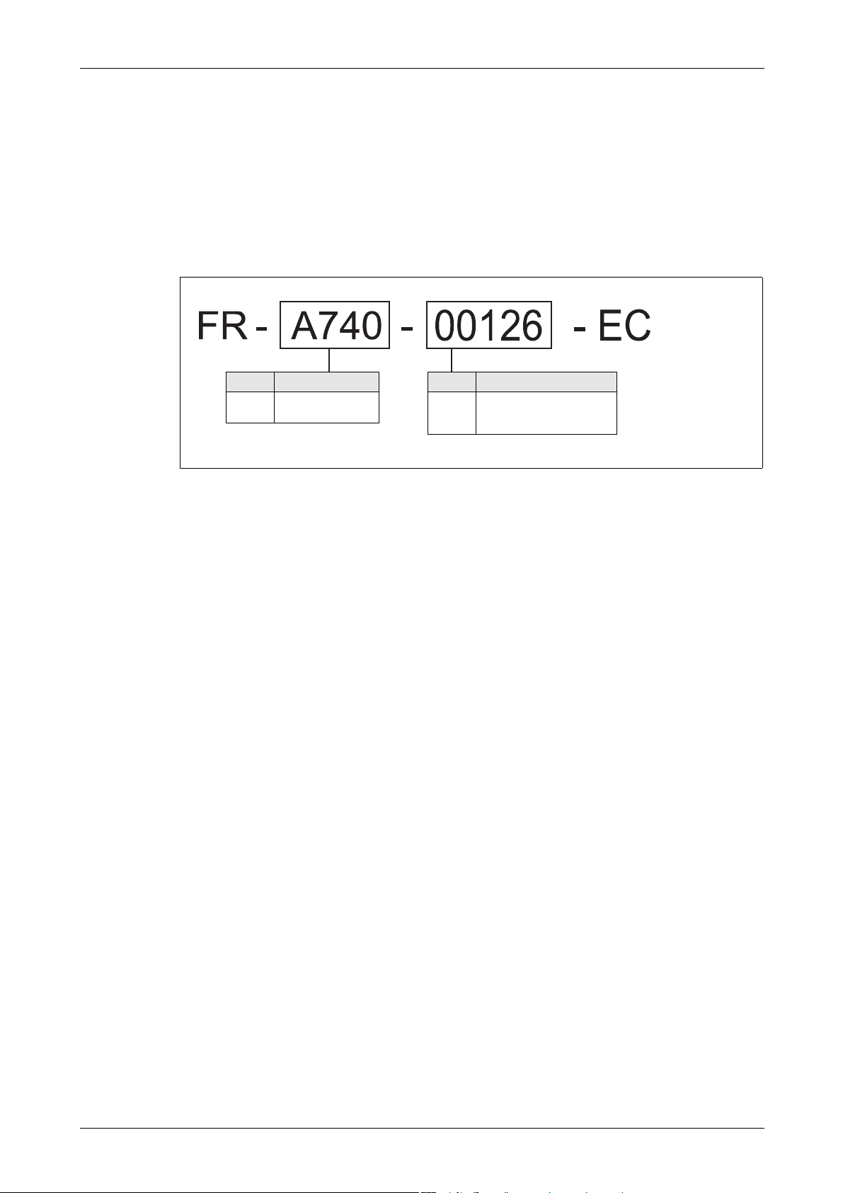
Product Checking and Part Identification Inverter Type
Symbol Voltage Class
A740
Three-phase
400V class
Symbol Type number
00023
to
12120
5-digit display
1 Product Checking and Part Identification
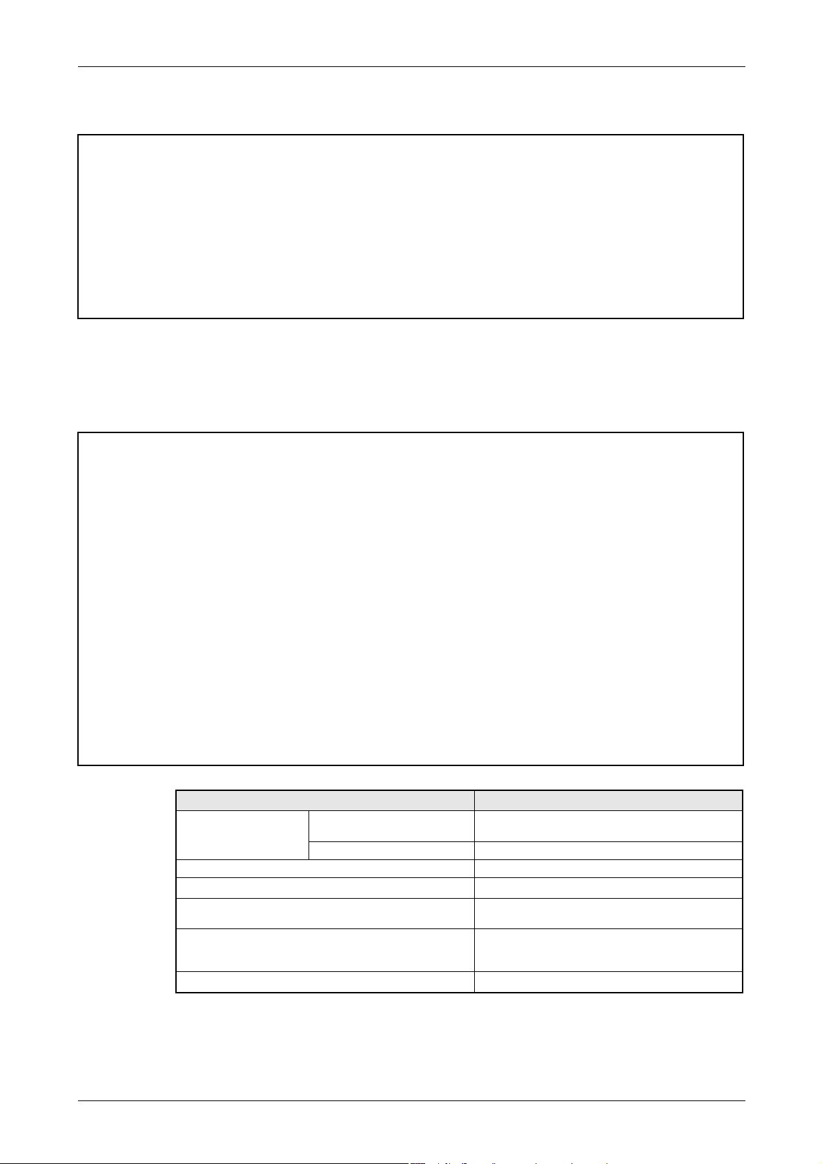
Unpack the inverter and check the capacity plate on the front cover and the rating plate on the
inverter side face to ensure that the product agrees with your order and the inverter is intact.
1.1 Inverter Type
I001410E
Fig. 1-1: Inverter type FR-A740 EC
FR-A700 EC 1 - 1

Description of the Case Product Checking and Part Identification
FR-A740-00126-EC
FR-A740-00126-EC
LD(50 C) XXA
SLD(40 C) XXA
ND(50 C) XXA
HD(50 C) XXA
Capacity plate
Capacity plate
Front cover
Inverter type
Input rating
Output rating
Serial number
Inverter type Serial number
RS-485 terminals
PU connector
(refer to section 3.5)
Rating plate
Comb shaped
wiring cover
(refer to section 2.3)
Control circuit
terminal block
(refer to section 3.4)
Main circuit
terminal block
(refer to section 3.3)
CHARGE lamp
Lit when power is
supplied to the
main circuit.
POWER lamp
Lit when the control circuit
(R1/L11, S1/L21) is supplied
with power
.
ALARM lamp
Lit when the inverter
is in the alarm status
(major fault)
(refer to chapter 7)
Connector with/without EMC filter
(refer to section 3.9.3)
AU/PTC-switchover
(refer to section 3.4)
Connector for plug-in option connection
(Refer to the instruction manual of options.)
Cooling fan
(refer to section 8.1.7)
Operation panel FR-DU07
(refer to section 4.3)
USB connector (refer to section 6.23.8)
Voltage/current input switch
(refer to section 3.1)
Overload capacity Ambient temperature
SLD 110% 60s, 120% 3s 40°C
LD 120% 60s, 150% 3s 50°C
ND 150% 60s, 200% 3s 50°C
HD 200% 60s, 250% 3s 50°C
1.2 Description of the Case
NOTE For removal and reinstallation of covers, refer to section 2.2.
1 - 2
Fig. 1-2: Appearance and Structure
I001411E

Product Checking and Part Identification Description of the Case
1.2.1 Accessory
Fan cover fixing screws
Capacity Screw Size[mm] Number
00083/00126 M3 × 35 1
00170 to 00380 M4 × 40 2
00470/00620 M4 × 50 1
Tab. 1-1: Fan cover fixing screws
NOTES The fan cover fixing screws are not delivered with models 00620 or less.
For removal and reinstallation of the cooling fans, refer to section 8.1.7.
DC reactor
For models 01800 or more the supplied DC reactor has to be installed.
Eyebolts
Two eyebolts (M8) for hanging the inverter are delivered with the models 00770 to
06830.
Jumper
A jumper is delivered with the model 01800 (refer to section 3.3.1).
FR-A700 EC 1 - 3

Description of the Case Product Checking and Part Identification
1 - 4
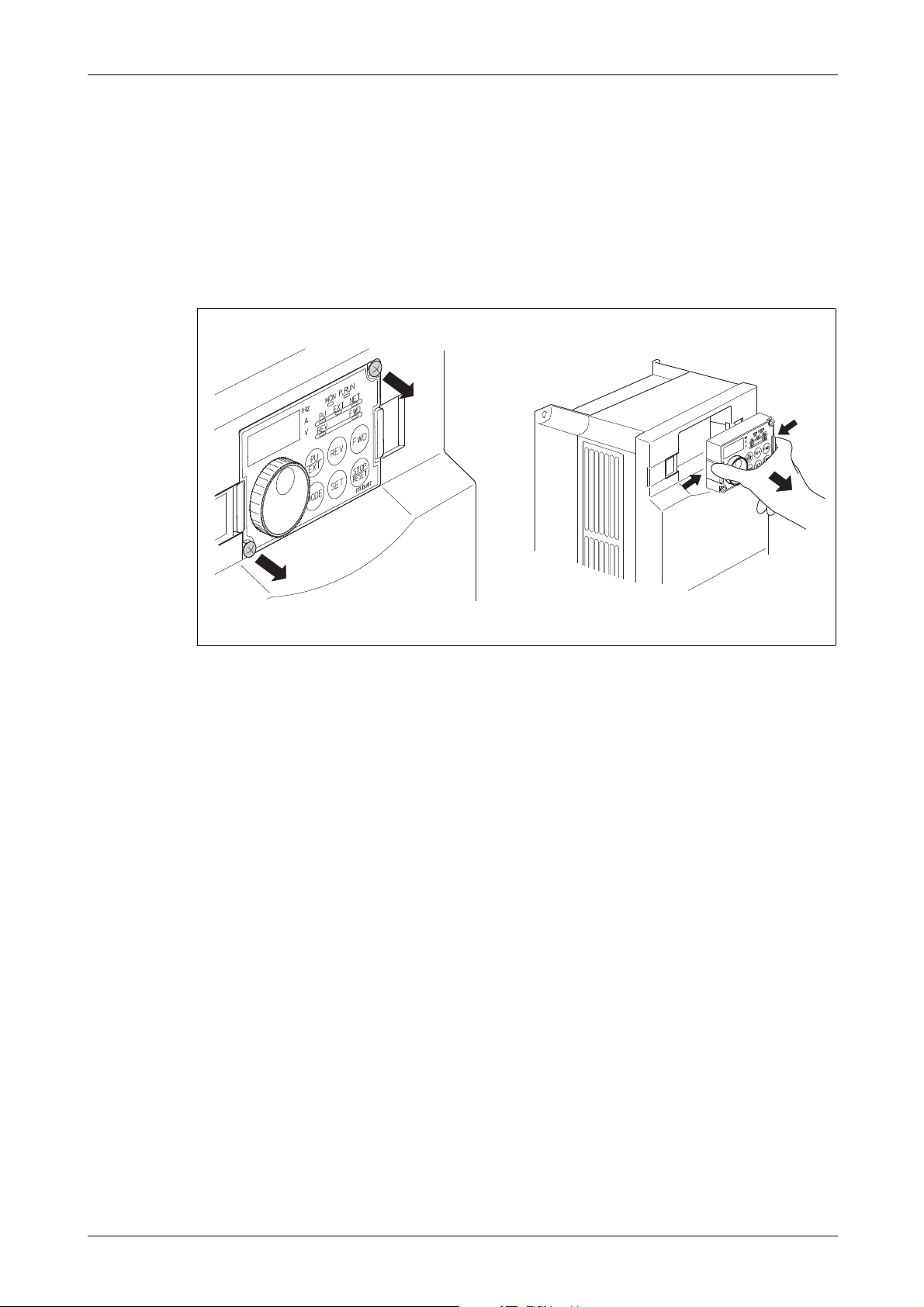
Installation Removal and reinstallation of the operation panel
Loosen the screws
Remove operation panel
2 Installation
2.1 Removal and reinstallation of the operation panel
Loosen the two screws on the operation panel. (These screws cannot be removed.)
Push the left and right hooks of the operation panel and pull the operation panel toward you
to remove.
I000991E
Fig. 2-1: Removal and reinstallation of the operation panel
When reinstalling the operation panel, insert it straight to reinstall securely and tighten the
fixed screws of the operation panel.
FR-A700 EC 2 - 1
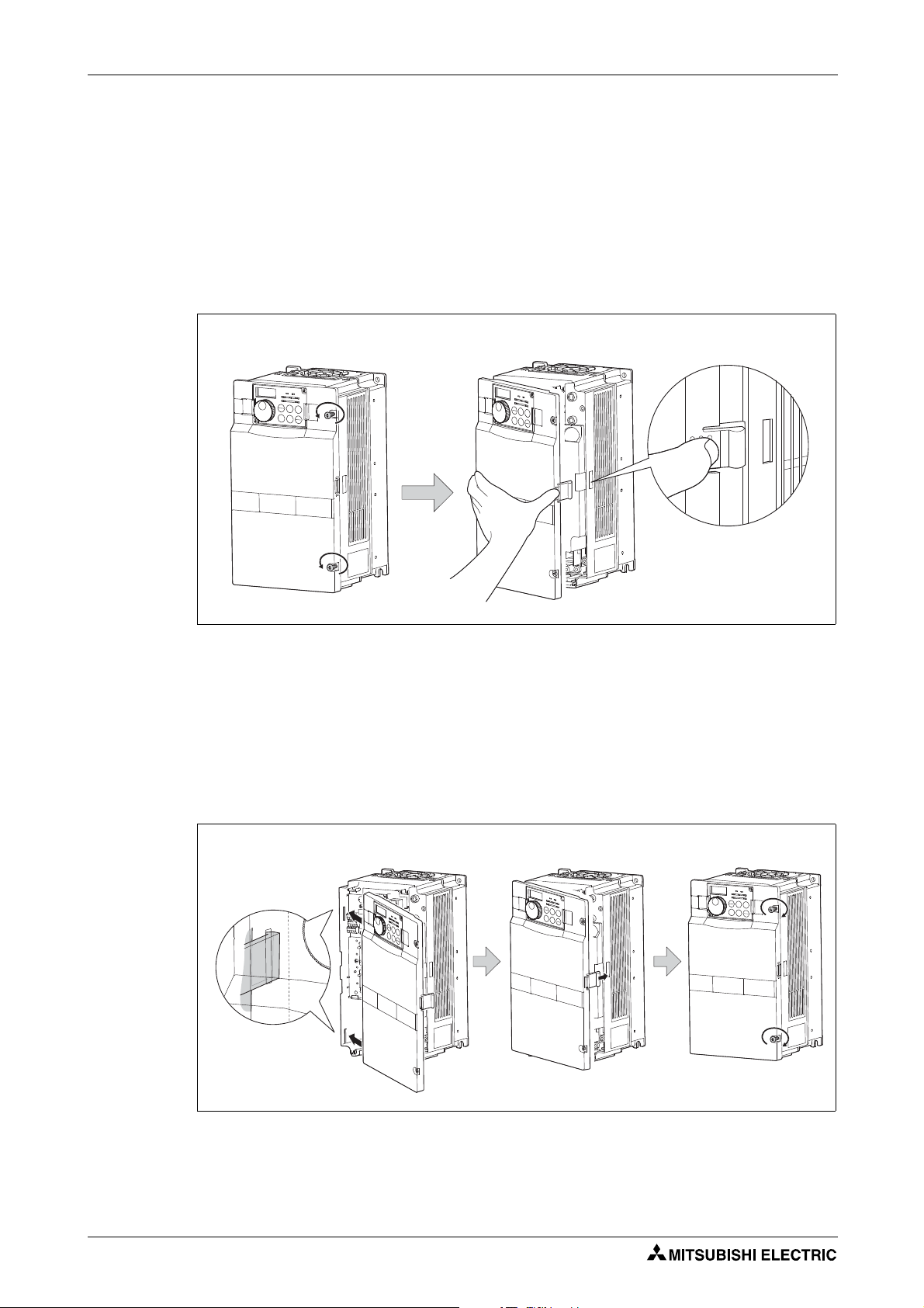
Removal and reinstallation of the front cover Installation
Loosen the screws
Remove front cover
Installation hook
Insert hooks into the sockets Press front cover against the inverter Tighten the installation screws
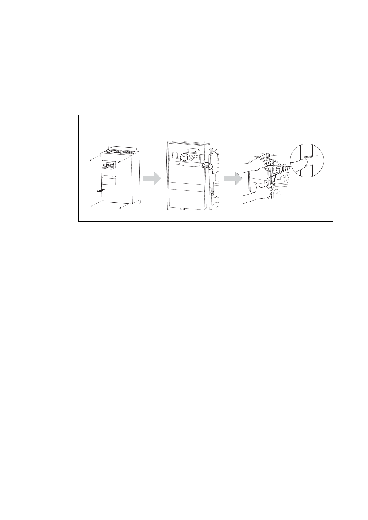
2.2 Removal and reinstallation of the front cover
2.2.1 FR-A740-00023 to 00620-EC
Removal
Loosen the installation screws of the front cover.
Pull the front cover toward you to remove by pushing an installation hook using left fixed
hooks as supports.
Fig. 2-2: Removal of the front cover
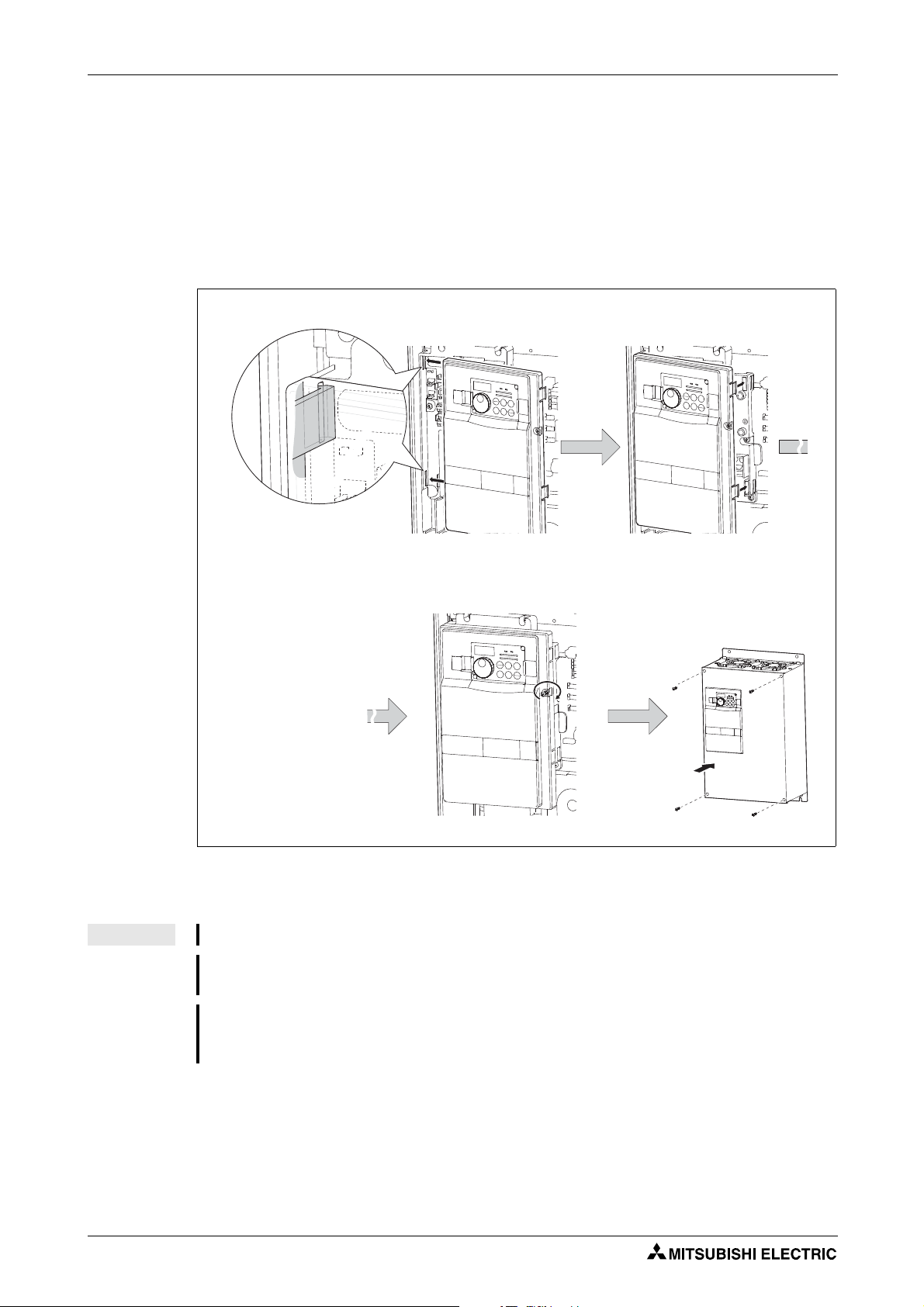
Reinstallation
Insert the two fixed hooks on the left side of the front cover into the sockets of the inverter.
Using the fixed hooks as supports, securely press the front cover against the inverter.
(Although installation can be done with the operation panel mounted, make sure that a
connector is securely fixed.)
Tighten the installation screws and fix the front cover.
I000992E
2 - 2
I000993E
Fig. 2-3: Reinstallation of the front cover
Installation Removal and reinstallation of the front cover
Loosen the screw of front
cover 1
Remove front cover
Installation hook
Front cover 1
Front cover 2
Loosen the screw of front
cover 2
2.2.2 FR-A740-00770 to 12120-EC
Removal
Loosen the installation screws of the front cover 1 to remove the front cover 1.
Loosen the installation screws of the front cover 2.
Pull the front cover 2 toward you to remove by pushing an installation hook on the right side
using left fixed hooks as supports.
Fig. 2-4: Removal of the front cover
I000994E
FR-A700 EC 2 - 3
Removal and reinstallation of the front cover Installation
Insert hooks into the sockets
Press front cover 2 against the inverter
Fix front cover 2 with the
installation screws
Fix front cover 1 with the
installation screws
Front cover 2
Front cover 1
Reinstallation
Insert the two fixed hooks on the left side of the front cover 2 into the sockets of the inverter.
Using the fixed hooks as supports, securely press the front cover 2 against the inverter.
(Although installation can be done with the operation panel mounted, make sure that a
connector is securely fixed.)
Fix the front cover 2 with the installation screws.
Fix the front cover 1 with the installation screws.
Fig. 2-5: Reinstallation of the front cover
NOTES For the FR-A740-04320 or more, the front cover 1 is separated into two parts.
Fully make sure that the front cover has been reinstalled securely. Always tighten the installation screws of the front cover.
The same serial number is printed on the capacity plate of the front cover and the rating
plate of the inverter. Before reinstalling the front cover, check the serial numbers to ensure
that the cover removed is reinstalled to the inverter from where it was removed.
I000995E
2 - 4

Installation Mounting
00023 to 00620 CAUTION:
When encasing multiple inverters, follow the
instructions on page 2-10.
00770 to 12120
R
e
f
e
r
t
o
F
i
g
.
2
-
8
:
Fix six positions for the FR-A740-04320
to 08660 and fix eight positions for the
FR-A740-09620 to 12120.
Direct sunlight
Vibration (≥ 5.9m/s²)
(2.9m/s² or more for the
04320 or more)
High temperature,
high humidity
Horizontal placement
Vertical mounting
(When installing two or more
inverters, install them in
parallel.)
Transportation by holding
the front cover
Oil mist, flammable gas,
corrosive gas, fluff, dust, etc.
Mounting to combustible
material
2.3 Mounting
I000997E
Fig. 2-6: Installation on the panel
The inverter consists of precision mechanical and electronic parts. Never install or handle it in
any of the following conditions as doing so could cause an operation fault or failure.
I000998E
Fig. 2-7: Conditions, that could cause an operation fault or failure
FR-A700 EC 2 - 5
Enclosure design Installation
2.4 Enclosure design
When an inverter enclosure is to be designed and manufactured, heat generated by contained
equipment, etc., the environment of an operating place, and others must be fully considered to
determine the enclosure structure, size and equipment layout. The inverter unit uses many
semiconductor devices. To ensure higher reliability and long period of operation, operate the inverter in the ambient environment that completely satisfies the equipment specifications.
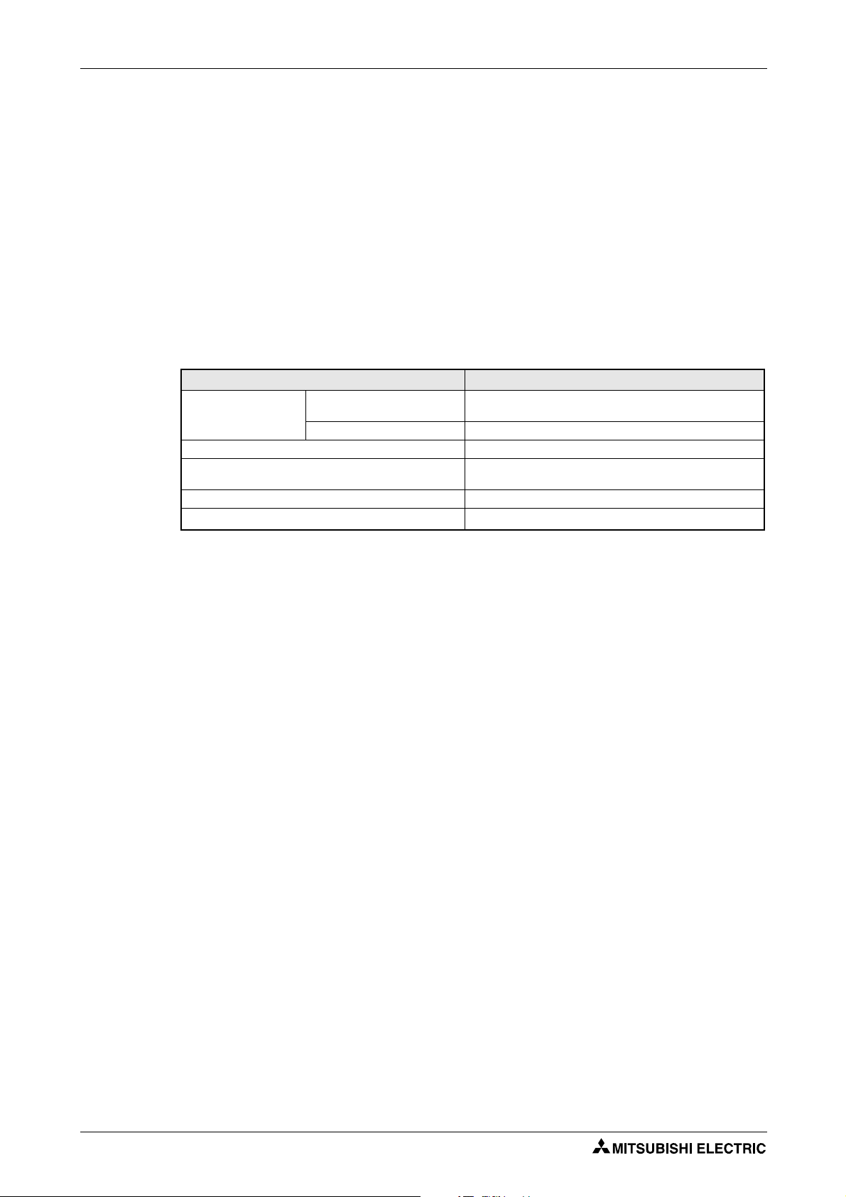
2.4.1 Inverter installation environment
As the inverter installation environment should satisfy the standard specifications indicated in
the following table, operation in any place that does not meet these conditions not only deteriorates the performance and life of the inverter, but also causes a failure. Refer to the following
points and take adequate measures.
Operating Condition FR-A740
LD (150%), ND (200%, initial
Ambient temperature
Ambient humidity 90% RH or less (non-condensing)
Atmosphere
Maximum altitude 1000m or less
Vibration 5.9m/s² or less (2.9m/s² or less for the 04320 or more.)
value) and HD (250%)
SLD (120%) −10°C to +40°C (non-freezing)
−10°C to +50°C (non-freezing)
Indoors (free from corrosive gas, flammable gas, oil mist,
dust and dirt)
Tab. 2-1: Environmental standard specifications of inverter
Temperature
The permissible ambient temperature of the inverter is between −10 and +50°C (when LD, ND
or HD is set) or −10 and +40°C (when SLD is set). Always operate the inverter within this temperature range. Operation outside this range will considerably shorten the service lives of the
semiconductors, parts, capacitors and others. Take the following measures so that the ambient
temperature of the inverter falls within the specified range.
● Measures against high temperature
– Use a forced ventilation system or similar cooling system. (Refer to page 2-9.)
– Install the enclosure in an air-conditioned electrical chamber.
– Block direct sunlight.
– Provide a shield or similar plate to avoid direct exposure to the radiated heat and wind
of a heat source.
– Ventilate the area around the enclosure well.
● Measures against low temperature
– Provide a space heater in the enclosure.
– Do not power off the inverter. (Keep the start signal of the inverter off.)
● Sudden temperature changes
2 - 6
– Select an installation place where temperature does not change suddenly.
– Avoid installing the inverter near the air outlet of an air conditioner.
– If temperature changes are caused by opening/closing of a door, install the inverter away
from the door.
 Loading...