

Mitsubishi Electric FR-A700-A1 Instruction Manual

INVERTER
FR-A700-A1
INSTRUCTION MANUAL
Dancer Control Function
Tension Control Function
CONTENTS
OUTLINE OF THE DEDICATED FUNCTIONS.............................................. 1
1
PARAMETER LIST ........................................................................................2
2
DANCER CONTROL/WINDING DIAMETER COMPENSATION ................14
3
3.1 Dedicated specification list ..................................................................................... 14
3.2 System configuration example ............................................................................... 15
3.3 Control block diagram............................................................................................. 15
3.4 Dedicated I/O signal ............................................................................................... 16
3.5 Parameter setting procedure for dancer control function ....................................... 19
3.6 Gain adjustment in actual operation ....................................................................... 22
3.7 Dancer control detail ............................................................................................... 25
3.8 Winding diameter compensation function .............................................................. 32
3.9 Main speed setting.................................................................................................. 43
3.10 Dedicated monitor function ..................................................................................... 49
3.11 Regeneration avoidance function (Pr. 882) ............................................................ 53
3.12 Operation command source and speed command source (Pr. 338, Pr. 339) ....... 53
1
2
TENSION CONTROL...................................................................................55
4
4.1 Dedicated function list............................................................................................. 55
4.2 System configuration example ............................................................................... 55
4.3 Block diagram of the control ................................................................................... 56
4.4 Dedicated I/O signal ............................................................................................... 56
4.5 Tension control parameter setting procedure......................................................... 57
4.6 Details of the tension control .................................................................................. 59
APPLICATION EXAMPLE...........................................................................67
5
5.1 Dancer control with winding diameter compensation for printers .......................... 67
5.2 Dancer control with winding diameter compensation for wiredrawing machine .... 70
5.3 Tension control for the winding operation of printers ............................................. 73
APPENDIX ................................................................................................... 74
6
6.1 Compatible plug-in options ..................................................................................... 74
6.2 Differences from the standard inverter ................................................................... 74
6.3 Parameter change when replacing FR-A500-A1 with FR-A700-A1 ...................... 75
6.4 Control mode-based parameter (function) correspondence and
instruction code....................................................................................................... 76
6.5 Index ....................................................................................................................... 80
3
4
5
6

—CONTENTS—
1 OUTLINE OF THE DEDICATED FUNCTIONS 1
2 PARAMETER LIST 2
3 DANCER CONTROL/WINDING DIAMETER COMPENSATION 14
3.1 Dedicated specification list ............................................................................................................. 14
3.2 System configuration example........................................................................................................ 15
3.3 Control block diagram...................................................................................................................... 15
3.4 Dedicated I/O signal ......................................................................................................................... 16
3.4.1 Input signal list ................................................................................................................................................... 16
3.4.2 Output signal list ................................................................................................................................................ 17
3.4.3 Analog input signals and pulse train input signals ............................................................................................. 18
3.5 Parameter setting procedure for dancer control function ............................................................ 19
3.6 Gain adjustment in actual operation............................................................................................... 22
3.6.1 Speed control P/I gain adjustment (Real sensorless vector control/Vector control) ..........................................22
3.6.2 Dancer PID gain adjustment.............................................................................................................................. 24
3.7 Dancer control detail ........................................................................................................................ 25
3.7.1 PID setting (Pr. 128 to Pr. 130, Pr. 134 to Pr. 137, Pr. 709, Pr. 710) ................................................................ 25
3.7.2 Dancer roll target position (Pr. 133, Pr. 702, Pr. 731)........................................................................................ 27
3.7.3 Adjustment of target position input (Pr. 708, C3, C4, C6, C7, C13, C15, C31, C33)......................................... 29
3.7.4 Measured value upper/lower limit detection signal (Pr. 131, Pr. 132) ............................................................... 29
3.7.5 PID gain switchover (Pr. 138, Pr. 270 to Pr. 278, Pr. 464 to Pr. 481, X89 signal, X90 signal) .......................... 29
3.7.6 Speed compensation (Pr. 706, Pr. 798) ............................................................................................................ 31
3.8 Winding diameter compensation function ..................................................................................... 32
3.8.1 Winding diameter calculation and compensation by winding diameter calculation ........................................... 32
3.8.2 Line speed input setting (Pr. 763 to Pr. 768) ..................................................................................................... 33
3.8.3 Setting at driving shaft (Pr. 762, Pr. 773, Pr. 774, X56 signal) .......................................................................... 34
3.8.4 Material thickness, maximum/minimum winding diameter setting
(Pr. 720 to Pr. 727, Pr. 752 to Pr. 755, X53 signal, X54 signal) ........................................................................ 35
3.8.5 Rotation speed at winding diameter calculated value activation (Pr. 797) ........................................................ 36
3.8.6 Storage and clear of winding diameter calculation result (Pr. 781 to Pr. 783, X55 signal)................................ 37
3.8.7 Sampling time and restricted increase of winding diameter (Pr. 707, Pr. 771, Pr. 772, Pr. 786)....................... 38
3.8.8 Filter treatment for compensated main rotation speed by winding diameter calculation (Pr. 769, Pr. 770)....... 38
3.8.9 Winding diameter calculation at start (Pr. 133, Pr. 712, Pr. 790 to Pr. 796)...................................................... 39
3.8.10 Storage and clear of winding/unwinding length (Pr. 279 to Pr. 281, X86 signal, Y53 signal) ............................ 42
3.9 Main speed setting ........................................................................................................................... 43
3.9.1 Input method of main speed command (Pr. 732) .............................................................................................. 43
3.9.2 Main speed command by analog input.............................................................................................................. 44
3.9.3 Main speed command by terminal JOG single-phase pulse train input
(Pr. 384 to Pr. 386, Pr. 703, Pr. 704) ................................................................................................................. 45
3.9.4 Acceleration/deceleration time setting (Pr. 756 to Pr. 761, X51 signal, X52 signal).......................................... 46
3.9.5 Speed control proportional gain selection based on winding diameter compensation result
(Pr. 775 to Pr. 780) ........................................................................................................................................... 47
3.9.6 Target winding diameter achieved signal (Pr. 750, Y52 signal)......................................................................... 48
3.10 Dedicated monitor function ............................................................................................................. 49
3.10.1 Dedicated monitor list ........................................................................................................................................ 49
3.10.2 Terminal 1 input voltage monitor ....................................................................................................................... 50
3.10.3 Winding diameter monitor.................................................................................................................................. 50
3.10.4 Line speed pulse monitor function..................................................................................................................... 50
CONTENTS
I

3.10.5 Multiple monitor (Pr. 52) .....................................................................................................................................50
3.10.6 Analog output signal for dancer tension setting (Pr. 718, Pr. 719, Pr. 733, Pr. 734,
Pr. 785, Pr. 787 to Pr. 789).................................................................................................................................51
3.11 Regeneration avoidance function (Pr. 882).................................................................................... 53
3.12 Operation command source and speed command source (Pr. 338, Pr. 339).............................. 53
4 TENSION CONTROL 55
4.1 Dedicated function list ..................................................................................................................... 55
4.2 System configuration example........................................................................................................ 55
4.3 Block diagram of the control ........................................................................................................... 56
4.3.1 Block diagram of the tension control ..................................................................................................................56
4.4 Dedicated I/O signal ......................................................................................................................... 56
4.4.1 Input signal list....................................................................................................................................................56
4.4.2 Output signal list .................................................................................................................................................56
4.5 Tension control parameter setting procedure ............................................................................... 57
4.6 Details of the tension control .......................................................................................................... 59
4.6.1 Winding diameter calculation during tension control (Pr. 797, X91 signal, Y51 signal)......................................59
4.6.2 Winding taper function (Pr. 717, Pr. 787, Pr. 788)..............................................................................................61
4.6.3 Inertia compensation function (Pr. 713 to Pr. 716, X57 signal, X58 signal, X59 signal).....................................62
4.6.4 Mechanical loss compensation (Pr. 739 to Pr. 749, Pr. 762) .............................................................................64
4.6.5 Stall operation signal (Pr. 737, Pr. 738, Pr. 760, X92 signal).............................................................................65
4.6.6 Tension control monitor output (Pr. 52) ..............................................................................................................66
5 APPLICATION EXAMPLE 67
5.1 Dancer control with winding diameter compensation for printers .............................................. 67
5.2 Dancer control with winding diameter compensation for wiredrawing machine ....................... 70
5.3 Tension control for the winding operation of printers.................................................................. 73
6 APPENDIX 74
6.1 Compatible plug-in options ............................................................................................................. 74
6.2 Differences from the standard inverter .......................................................................................... 74
6.3 Parameter change when replacing FR-A500-A1 with FR-A700-A1............................................... 75
6.4 Control mode-based parameter (function) correspondence and
instruction code ................................................................................................................................ 76
6.5 Index .................................................................................................................................................. 80
II
1
OUTLINE OF THE DEDICATED FUNCTIONS
1 OUTLINE OF THE DEDICATED FUNCTIONS
The following dedicated functions for winding and unwinding machine are added to FR-A700 series standard inverter. In this
supplementary instruction manual, specifications of the new functions are included. Refer to the FR-A700 Instruction Manuals
for functions not explained in this supplementary instruction manual.
This product is useful when difference between minimum diameter and maximum diameter is great and when feeding speed
is fast in winding machine with dancer roll.
The inverter torque is controlled by the tension control, inertia compensation and mechanical loss compensation. Thus,
dancer rolls and tension controllers are not required to roll up a sheet of paper when using this product.
This product is also useful for wiredrawing machine and to roll up paper in a printer.
• Dancer control function
• Winding diameter compensation function
• Tension control function
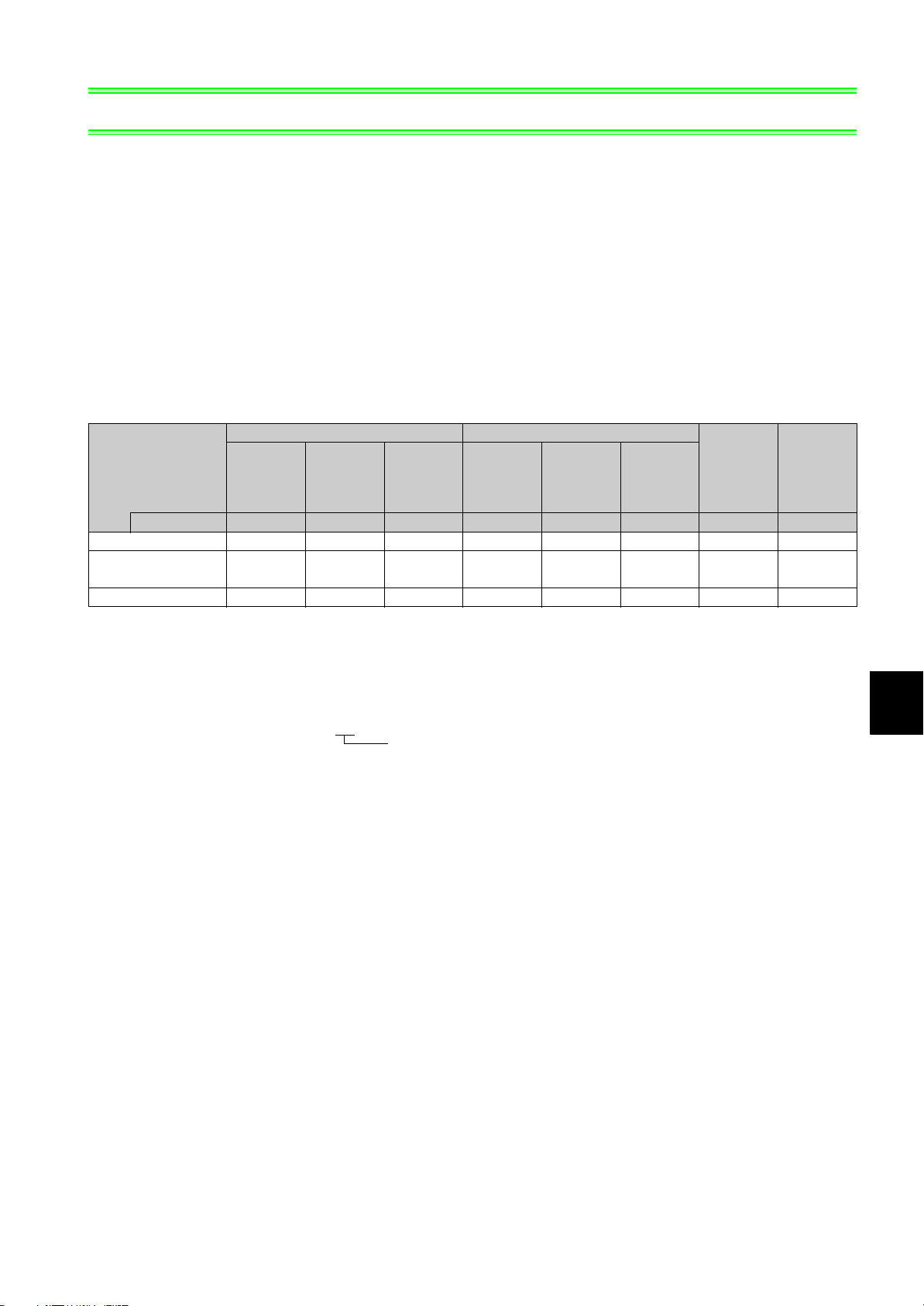
The following table shows valid control methods for each function.
Vector Control Real Sensorless Vector Control
Tensio n
Function
Pr.800 setting 0, 2 1, 2 6 10, 12 11, 12 16 20 20
Dancer control
Winding diameter
compensation function
Tension Control
Speed
Control
Torque
Control
control
(Torque
Control)
Speed
Control
Tor que
Control
Tension
control
(Torque
Control)
Advanced
Magnetic
Flux
Vec to r
Control
: available, : unavailable
V/F
Control
Inverters with dancer control function, winding diameter compensation function and tension control function are indicated with
"-A1" at the end of their model names.
[Example]
FR-A720-1.5K-A1
Inverters with dancer control function, winding
diameter compensation function and tension
control function (for every capacity)
1
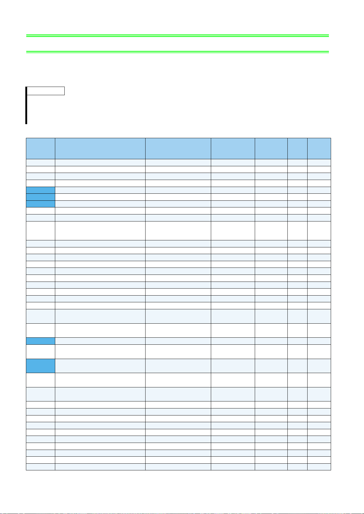
PARAMETER LIST
2 PARAMETER LIST
Set the necessary parameters to meet the load and operational specifications. Parameter setting, change and check can be
made from the operation panel (FR-DU07). For the parameters not described in this Instruction Manual, refer to the Instruction
Manual of FR-A700 series.
REMARKS
• The shaded parameters in the table allow their settings to be changed during operation even if "0" (initial value) is set in Pr. 77 Parameter
write selection.
• Refer to the page 76 for instruction codes for communication and availability of parameter clear, all clear, and parameter copy of each
parameter.
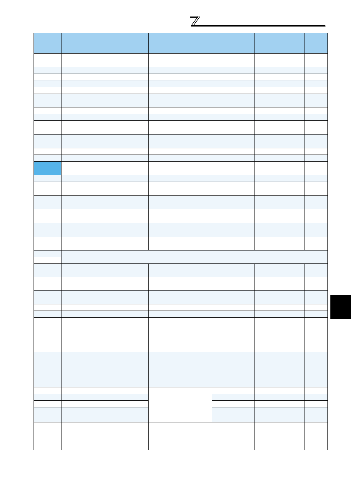
Parameter
Name Setting Range
Setting
Increments
0 Torque boost 0 to 30% 0.1% 6/4/3/2/1% *1 —
1 Maximum frequency 0 to 120Hz 0.01Hz 120/60Hz *2 —
2 Minimum frequency 0 to 120Hz 0.01Hz 0Hz —
3 Base frequency 0 to 400Hz 0.01Hz 60Hz —
4 Multi-speed setting (high speed) 0 to 400Hz 0.01Hz 60Hz —
5 Multi-speed setting (middle speed) 0 to 400Hz 0.01Hz 30Hz —
6 Multi-speed setting (low speed) 0 to 400Hz 0.01Hz 10Hz —
7 Acceleration time 0 to 3600/360s 0.1/0.01s 5/15s *3 —
8 Deceleration time 0 to 3600/360s 0.1/0.01s 5/15s *3 —
Minimum
9 Electronic thermal O/L relay 0 to 500/0 to 3600A *2 0.01
10 DC injection brake operation frequency 0 to 120Hz, 9999 0.01Hz 3Hz —
11 DC injection brake operation time 0 to 10s, 8888 0.1s 0.5s —
12 DC injection brake operation voltage 0 to 30% 0.1% 4/2/1% *4 —
13 Starting frequency 0 to 60Hz 0.01Hz 0.5Hz —
14 Load pattern selection 0 to 5 1 0 —
15 Jog frequency 0 to 400Hz 0.01Hz 5Hz —
16 Jog acceleration/deceleration time 0 to 3600/360s 0.1/0.01s 0.5s —
17 MRS input selection 0, 2, 4 1 0 —
18 High speed maximum frequency 120 to 400Hz 0.01Hz 120/60Hz *2 —
19 Base frequency voltage 0 to 1000V, 8888, 9999 0.1V 9999 —
20
21
22 Stall prevention operation level 0 to 400% 0.1% 150% —
23
24 to 27
28
29
30 Regenerative function selection 0, 1, 2, 10, 11, 20, 21 1 0 —
31 Frequency jump 1A 0 to 400Hz, 9999 0.01Hz 9999 —
32 Frequency jump 1B 0 to 400Hz, 9999 0.01Hz 9999 —
33 Frequency jump 2A 0 to 400Hz, 9999 0.01Hz 9999 —
34 Frequency jump 2B 0 to 400Hz, 9999 0.01Hz 9999 —
35 Frequency jump 3A 0 to 400Hz, 9999 0.01Hz 9999 —
36 Frequency jump 3B 0 to 400Hz, 9999 0.01Hz 9999 —
37 Speed display 0, 1 to 9998 1 0 —
41 Up-to-frequency sensitivity 0 to 100% 0.1% 10% —
42 Output frequency detection 0 to 400Hz 0.01Hz 6Hz —
Acceleration/deceleration reference
frequency
Acceleration/deceleration time
increments
Stall prevention operation level
compensation factor at double speed
Multi-speed setting (4 speed to 7
speed)
Multi-speed input compensation
selection
Acceleration/deceleration pattern
selection
1 to 400Hz 0.01Hz 60Hz —
0, 1 1 0 —
0 to 200%, 9999 0.1% 9999 —
0 to 400Hz, 9999 0.01Hz 9999 —
0, 1 1 0 —
0 to 5 1 0 —
/0.1
A *2
Initial
Value
Rated
inverter
current
Refer
to
Page
—
Customer
Setting
2
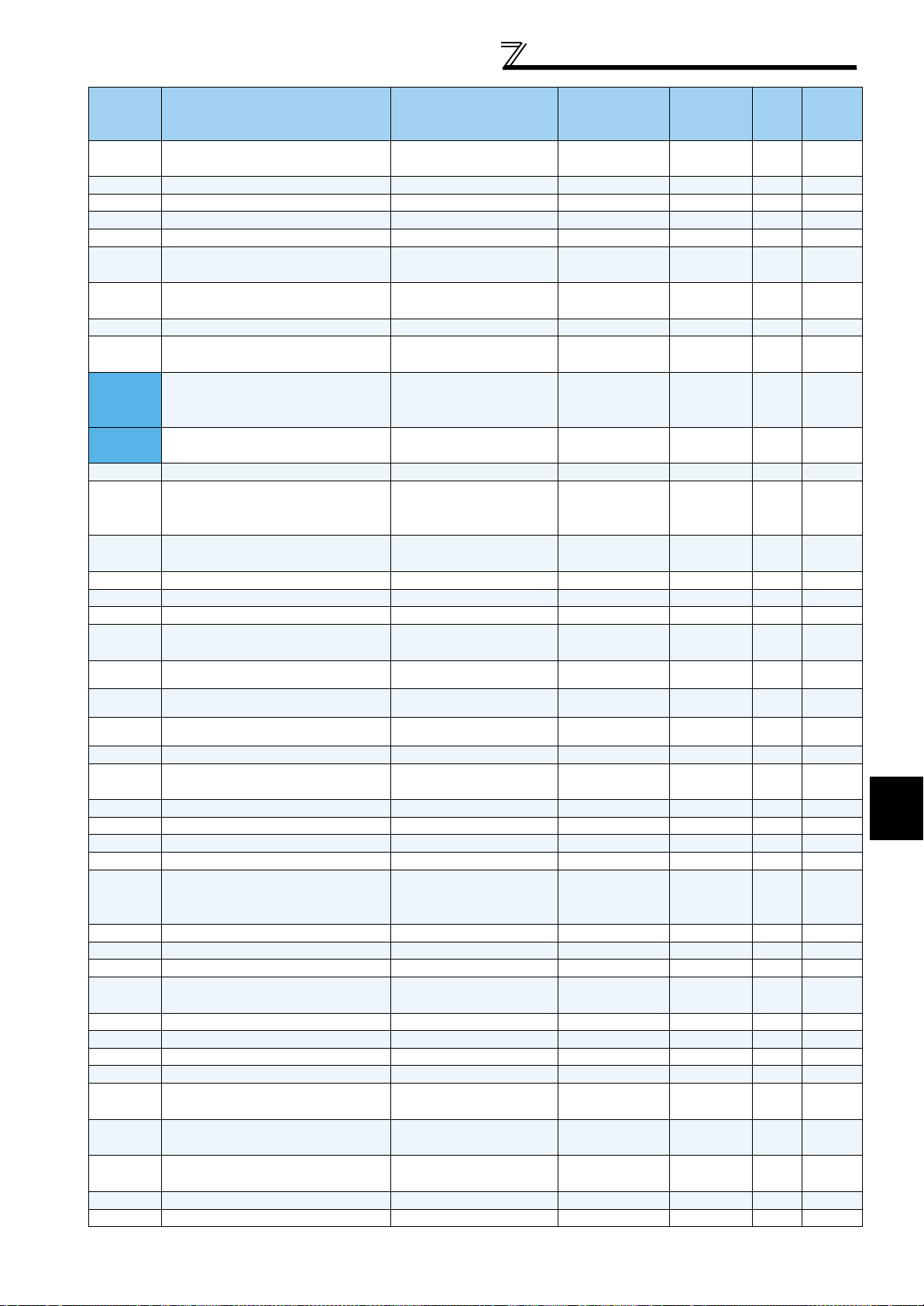
PARAMETER LIST
2
PARAMETER LIST
Minimum
Parameter
Name Setting Range
Setting
Increments
43
44 Second acceleration/deceleration time 0 to 3600/360s 0.1/0.01s 5s —
45 Second deceleration time 0 to 3600/360s, 9999 0.1/0.01s 9999 —
46 Second torque boost 0 to 30%, 9999 0.1% 9999 —
47 Second V/F (base frequency) 0 to 400Hz, 9999 0.01Hz 9999 —
48
49
50 Second output frequency detection 0 to 400Hz 0.01Hz 30Hz —
51 Second electronic thermal O/L relay
52 DU/PU main display data selection
54 FM terminal function selection
55 Frequency monitoring reference 0 to 400Hz 0.01Hz 60Hz —
56 Current monitoring reference 0 to 500/0 to 3600A *2 0.01/0.1A *2
57 Restart coasting time
58 Restart cushion time 0 to 60s 0.1s 1s —
59 Remote function selection 0, 1, 2, 3 1 0 —
60 Energy saving control selection 0, 4 1 0 —
61 Reference current
62 Reference value at acceleration 0 to 220%, 9999 0.1% 9999 —
Output frequency detection for reverse
rotation
Second stall prevention operation
current
Second stall prevention operation
frequency
0 to 400Hz, 9999 0.01Hz 9999 —
0 to 220% 0.1% 150% —
0 to 400Hz, 9999 0.01Hz 0Hz —
0 to 500A, 9999/
0 to 3600A, 9999
0, 5 to 14, 17, 18, 20, 21,
23 to 27, 32 to 35, 39 to 46,
52 to 57, 62 to 65, 100
1 to 3, 5 to 14, 17, 18, 21,
24, 32 to 34, 39 to 44, 46
0, 0.1 to 5s, 9999/
0, 0.1 to 30s, 9999
0 to 500A, 9999/
0 to 3600A, 9999
*2
*2
*2
0.01/0.1A *2 9999 —
1 0 49
1149
0.1s 9999 —
0.01/0.1A *2 9999 —
Initial
Value
Rated
inverter
current
Refer
to
Page
—
Customer
Setting
63 Reference value at deceleration 0 to 220%, 9999 0.1% 9999 —
64 Starting frequency for elevator mode 0 to 10Hz, 9999 0.01Hz 9999 —
65 Retry selection 0 to 5 1 0 —
66
67 Number of retries at fault occurrence 0 to 10, 101 to 110 1 0 —
68 Retry waiting time 0 to 10s 0.1s 1s —
69 Retry count display erase 0 1 0 —
70 Special regenerative brake duty 0 to 30%/0 to 10% *2 0.1% 0% —
71 Applied motor
72 PWM frequency selection 0 to 15/0 to 6, 25 *2 12—
73 Analog input selection 0 to 7, 10 to 17 1 1 —
74 Input filter time constant 0 to 8 1 1 —
75
76 Fault code output selection 0, 1, 2 1 0 —
77 Parameter write selection 0, 1, 2 1 0 —
78 Reverse rotation prevention selection 0, 1, 2 1 0 —
79 Operation mode selection 0, 1, 2, 3, 4, 6, 7 1 0 —
80 Motor capacity
81 Number of motor poles
82 Motor excitation current
83 Rated motor voltage 0 to 1000V 0.1V 200/400V *5 —
84 Rated motor frequency 10 to 120Hz 0.01Hz 60Hz —
Stall prevention operation reduction
starting frequency
Reset selection/disconnected PU
detection/PU stop selection
0 to 400Hz 0.01Hz 60Hz —
0, 1, 3 to 8, 13 to 18, 20, 23,
24, 30, 33, 34, 40, 43, 44,
50, 53, 54
0 to 3, 14 to 17 1 14 —
0.4 to 55kW, 9999/
0 to 3600kW, 9999
2, 4, 6, 8, 10, 12, 14, 16, 18,
20, 9999
0 to 500A, 9999/
0 to 3600A, 9999
*2
*2
1 0 —
0.01/0.1kW *2 9999 —
1 9999 —
0.01/0.1A *2 9999 —
3
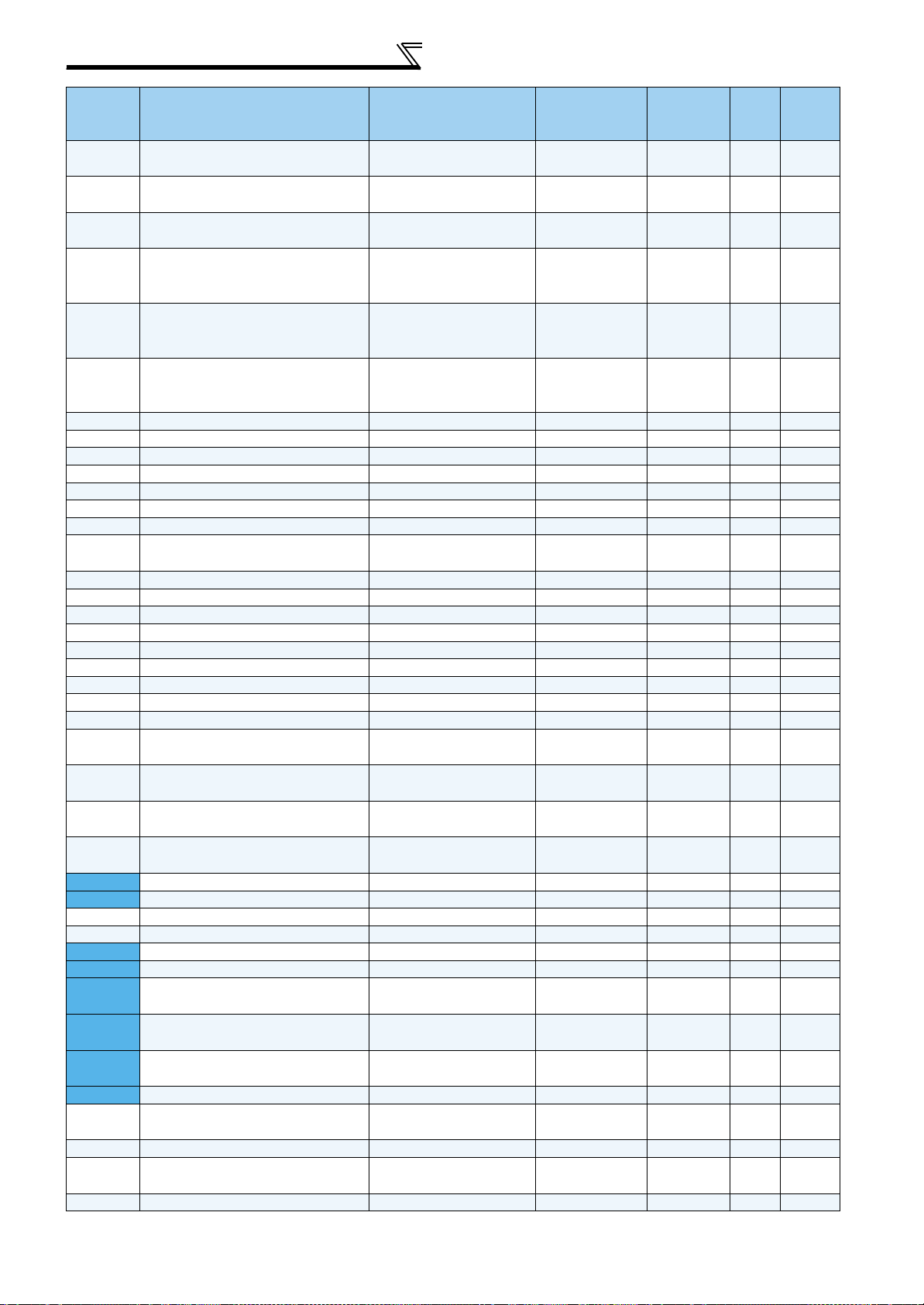
PARAMETER LIST
Parameter
89
90 Motor constant (R1)
91 Motor constant (R2)
92 Motor constant (L1)
93 Motor constant (L2)
94 Motor constant (X)
Speed control gain (advanced magnetic
flux vector)
Name Setting Range
0 to 200%, 9999 0.1% 9999 —
0 to 50, 9999/
0 to 400m, 9999
0 to 50, 9999/
0 to 400m, 9999
0 to 50(0 to 1000mH),
9999/0 to 3600m(0 to
400mH), 9999
0 to 50(0 to 1000mH),
9999/0 to 3600m(0 to
400mH), 9999
0 to 500(0 to 100%),
9999/0 to 100(0 to
100%), 9999
*2
*2
*2
*2
*2
Minimum
Setting
Increments
0.001/0.01m *2 9999 —
0.001/
*2
0.01m
0.001(0.1mH)/
0.01m(0.01mH)
*2
0.001(0.1mH)/
0.01m(0.01mH)
*2
0.01(0.1%)/
0.01(0.01%)
Initial
Value
9999 —
9999 —
9999 —
*2
9999 —
95 Online auto tuning selection 0 to 2 1 0 —
96 Auto tuning setting/status 0, 1, 101 1 0 —
110 Third acceleration/deceleration time 0 to 3600/360s, 9999 0.1/0.01s 9999 —
111 Third deceleration time 0 to 3600/360s, 9999 0.1/0.01s 9999 —
112 Third torque boost 0 to 30%, 9999 0.1% 9999 —
113 Third V/F (base frequency) 0 to 400Hz, 9999 0.01Hz 9999 —
114 Third stall prevention operation current 0 to 220% 0.1% 150% —
115
Third stall prevention operation
frequency
0 to 400Hz 0.01Hz 0 —
116 Third output frequency detection 0 to 400Hz 0.01Hz 60Hz —
117 PU communication station number 0 to 31 1 0 —
118 PU communication speed 48, 96, 192, 384 1 192 —
119 PU communication stop bit length 0, 1, 10, 11 1 1 —
120 PU communication parity check 0, 1, 2 1 2 —
121 Number of PU communication retries 0 to 10, 9999 1 1 —
122 PU communication check time interval 0, 0.1 to 999.8s, 9999 0.1s 9999 —
123 PU communication waiting time setting 0 to 150ms, 9999 1 9999 —
124 PU communication CR/LF selection 0, 1, 2 1 1 —
125
126
127
128 PID action selection
Terminal 2 frequency setting gain
frequency
Terminal 4 frequency setting gain
frequency
PID control automatic switchover
frequency
0 to 400Hz 0.01Hz 60Hz —
0 to 400Hz 0.01Hz 60Hz —
0 to 400Hz, 9999 0.01Hz 9999 —
10, 11, 40, 41, 50, 51, 60,
61
1 40 25
129 PID proportional band 0.1 to 1000%, 9999 0.1% 100% 25
130 PID integral time 0.1 to 3600s, 9999 0.1s 1s 25
131 PID upper limit 400 to 600%, 9999 0.1% 9999 29
132 PID lower limit 400 to 600%, 9999 0.1% 9999 29
133 Target dancer position 400 to 600%, 9999 0.01% 500% 27, 39
134 PID differential time 0.01 to 10.00s, 9999 0.01s 9999 26
135
136
137
PID proportional band for under-set
point value
PID integral time for under-set point
value
PID differential time for under-set point
value
0.1 to 1000%, 9999 0.1% 9999 26
0.1 to 3600s, 9999 0.1s 9999 26
0.01 to 10.00s, 9999 0.01s 9999 26
138 Integral control presence/absence 0 to 3 1 0 30
140
Backlash acceleration stopping
frequency
0 to 400Hz 0.01Hz 1Hz —
141 Backlash acceleration stopping time 0 to 360s 0.1s 0.5s —
142
Backlash deceleration stopping
frequency
0 to 400Hz 0.01Hz 1Hz —
143 Backlash deceleration stopping time 0 to 360s 0.1s 0.5s —
Refer
to
Page
Customer
Setting
4
PARAMETER LIST
2
PARAMETER LIST
Minimum
Parameter
Name Setting Range
Setting
Increments
144 Speed setting switchover
145 PU display language selection 0 to 7 1 0 —
148 Stall prevention level at 0V input 0 to 220% 0.1% 150% —
149 Stall prevention level at 10V input 0 to 220% 0.1% 200% —
150 Output current detection level 0 to 220% 0.1% 150% —
151
152 Zero current detection level 0 to 220% 0.1% 5% —
153 Zero current detection time 0 to 1s 0.01s 0.5s —
154
155
156 Stall prevention operation selection 0 to 31, 100, 101 1 0 —
157 OL signal output timer 0 to 25s, 9999 0.1s 0s —
158 AM terminal function selection
160 User group read selection 0, 1, 9999 1 0 —
161
162
165
166
167
168
169
170 Watt-hour meter clear 0, 10, 9999 1 9999 —
Output current detection signal delay
time
Voltage reduction selection during stall
prevention operation
RT signal function validity condition
selection
Frequency setting/key lock operation
selection
Automatic restart after instantaneous
power failure selection
Stall prevention operation level for
restart
Output current detection signal
retention time
Output current detection operation
selection
Parameter for manufacturer setting. Do not set.
0, 2, 4, 6, 8, 10, 102, 104,
106, 108, 110
0 to 10s 0.1s 0s —
0, 1 1 1 —
0, 10 1 0 —
1 to 3, 5 to 14, 17, 18, 21,
24, 32 to 34, 39 to 44, 46
0, 1, 10, 11 1 0 —
0, 1, 2, 10, 11, 12 1 0 —
0 to 220% 0.1% 150% —
0 to 10s, 9999 0.1s 0.1s —
0, 1 1 0 —
14—
1149
Initial
Value
Refer
to
Page
Customer
Setting
171 Operation hour meter clear 0, 9999 1 9999 —
172
173 User group registration 0 to 999, 9999 1 9999 —
174 User group clear 0 to 999, 9999 1 9999 —
178 STF terminal function selection
179 STR terminal function selection
180 RL terminal function selection 0 to 14, 16 to 18, 20,
181 RM terminal function selection 1 1 16
182 RH terminal function selection 1 2 16
183 RT terminal function selection 1 3 16
184 AU terminal function selection
User group registered display/batch
clear
9999, (0 to 16) 1 0 —
0 to 14, 16 to 18, 20,
22 to 28, 30, 32 to 35,
42 to 44, 51 to 60, 62,
64 to 67, 70, 71, 83 to 93,
9999
0 to 14, 16 to 18, 20,
23 to 28, 30, 32 to 35,
42 to 44, 51 to 59, 61, 62,
64 to 67, 70, 71, 83 to 93,
9999
23 to 28, 30, 32 to 35,
42 to 44, 51 to 59, 62,
64 to 67, 70, 71, 83 to 93,
9999
0 to 14, 16 to 18, 20,
23 to 28, 30, 32 to 35,
42 to 44, 51 to 59, 62 to 67,
70, 71, 74, 83 to 93, 9999
16016
1 61 16
1016
1416
5
PARAMETER LIST
Minimum
Parameter
Name Setting Range
Setting
Increments
185 JOG terminal function selection
186 CS terminal function selection 1 6 16
187 MRS terminal function selection 1 24 16
188 STOP terminal function selection 1 25 16
189 RES terminal function selection 1 62 16
190 RUN terminal function selection
191 SU terminal function selection 1 1 17
192 IPF terminal function selection 1 2 17
193 OL terminal function selection 1 3 17
194 FU terminal function selection 1 4 17
195 ABC1 terminal function selection
196 ABC2 terminal function selection 1 9999 17
232 to 239
240 Soft-PWM operation selection 0, 1 1 1 —
241 Analog input display unit switchover 0, 1 1 0 —
242
243
244 Cooling fan operation selection 0, 1 1 1 —
245 Rated slip 0 to 50%, 9999 0.01% 9999 —
246 Slip compensation time constant 0.01 to 10s 0.01s 0.5s —
247
251 Output phase loss protection selection 0, 1 1 1 —
252 Override bias 0 to 1000% 0.1% 50% 44
Multi-speed setting (8 speed to 15
speed)
Terminal 1 added compensation
amount (terminal 2)
Terminal 1 added compensation
amount (terminal 4)
Constant-power range slip
compensation selection
0 to 20, 22 to 28, 30,
32 to 35, 42 to 44, 62,
64 to 71, 74, 76, 83, 9999
0 to 8, 10 to 16, 25, 26,
30 to 35, 39, 41 to 47,
50 to 54, 64, 70, 85, 90, 91,
93 to 99, 100 to 108,
110 to 116, 125, 126,
130 to 135, 139, 141 to 147,
150 to 154, 164, 170, 185,
190, 191, 193 to 199, 9999
0 to 8, 10 to 16, 25, 26,
30 to 35, 39, 41 to 47,
50 to 54, 64, 70, 85, 90, 91,
94 to 99, 100 to 108,
110 to 116, 125, 126,
130 to 135, 139, 141 to 147,
150 to 154, 164, 170, 185,
190, 191, 194 to 199, 9999
0 to 400Hz, 9999 0.01Hz 9999 —
0 to 100% 0.1% 100% —
0 to 100% 0.1% 75% —
0, 9999 1 9999 —
1 5 16
1017
1 99 17
Initial
Value
Refer
to
Page
Customer
Setting
253 Override gain 0 to 1000% 0.1% 150% 44
255 Life alarm status display (0 to 15) 1 0 —
256 Inrush current limit circuit life display (0 to 100%) 1% 100% —
257 Control circuit capacitor life display (0 to 100%) 1% 100% —
258 Main circuit capacitor life display (0 to 100%) 1% 100% —
259 Main circuit capacitor life measuring 0, 1 1 0 —
261 Power failure stop selection 0, 1, 2, 11, 12 1 0 —
262
263 Subtraction starting frequency 0 to 120Hz, 9999 0.01Hz 60Hz —
264 Power-failure deceleration time 1 0 to 3600/ 360s 0.1/0.01s 5s —
265 Power-failure deceleration time 2 0 to 3600/ 360s, 9999 0.1/0.01s 9999 —
266
267 Terminal 4 input selection 0, 1, 2 1 0 —
268 Monitor decimal digits selection 0, 1, 9999 1 9999 —
269 Parameter for manufacturer setting. Do not set.
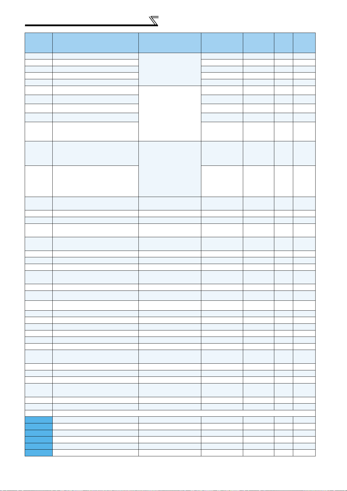
270 Dancer position A 400.1% to 600% 0.1% 600% 30
271 Dancer position B 400% to 599.9% 0.1% 400% 30
272 Dancer position C1 400.1% to 599.9%, 9999 0.1% 9999 30
273 Dancer position C2 400.1% to 599.9%, 9999 0.1% 9999 30
274 PID position gain A 0.1 to 1000%, 9999 0.1% 9999 30
275 PID position gain B 0.1 to 1000%, 9999 0.1% 9999 30
Subtracted frequency at deceleration
start
Power failure deceleration time
switchover frequency
0 to 20Hz 0.01Hz 3Hz —
0 to 400Hz 0.01Hz 60Hz —
6
PARAMETER LIST
2
PARAMETER LIST
Minimum
Parameter
Name Setting Range
Setting
Increments
276 PID position gain C1 0.1 to 1000%, 9999 0.1% 9999 30
277 PID position gain C2 0.1 to 1000%, 9999 0.1% 9999 30
278 PID position gain D 0.1 to 1000%, 9999 0.1% 9999 30
279 Winding/unwinding length detection 0 to 9999 1 1000 42
280 Winding/unwinding length unit 0, 1, 2, 3 1 0 42
281 Stored winding/unwinding length 0 to 9999 1 0 42
Overspeed detection frequency
285
286 Droop gain 0 to 100% 0.1% 0% —
287 Droop filter time constant 0 to 1s 0.01s 0.3s —
288 Droop function activation selection 0, 1, 2, 10, 11 1 0 —
291 Pulse train I/O selection 0, 1, 10, 11, 20, 21, 100 1 0 —
292 Automatic acceleration/deceleration 0, 1, 3, 5, 6, 11 1 0 —
293
294 UV avoidance voltage gain 0 to 200% 0.1% 100% —
299
331 RS-485 communication station number 0 to 31(0 to 247) 1 0 —
332 RS-485 communication speed
333 RS-485 communication stop bit length 0, 1, 10, 11 1 1 —
334
335 RS-485 communication retry count 0 to 10, 9999 1 1 —
336
337
338
339
340 Communication startup mode selection 0, 1, 2, 10, 12 1 0 —
341
342
343 Communication error count — 1 0 —
359 *6 Encoder rotation direction 0, 1 1 1 —
369 *6 Number of encoder pulses 0 to 4096 1 1024 —
374 Overspeed detection level 0 to 400Hz 0.01Hz 140Hz —
376 *6
380 Acceleration S-pattern 1 0 to 50% 1% 0 —
381 Deceleration S-pattern 1 0 to 50% 1% 0 —
382 Acceleration S-pattern 2 0 to 50% 1% 0 —
383 Deceleration S-pattern 2 0 to 50% 1% 0 —
384 Input pulse division scaling factor 0 to 250 1 0 45
385 Frequency for zero input pulse 0 to 400Hz 0.01Hz 0 45
386 Frequency for maximum input pulse 0 to 400Hz 0.01Hz 60Hz 45
428 *6 Command pulse selection 0 to 5 1 0 —
450 Second applied motor
451 Second motor control method selection 10, 11, 12, 20, 9999 1 9999 —
453 Second motor capacity
454 Number of second motor poles 2, 4, 6, 8, 10, 9999 1 9999 —
(Excessive speed deviation detection
frequency)
Acceleration/deceleration separate
selection
Rotation direction detection selection at
restarting
RS-485 communication parity check
selection
RS-485 communication check time
interval
RS-485 communication waiting time
setting
Communication operation command
source
Communication speed command
source
RS-485 communication CR/LF
selection
Communication EEPROM write
selection
Encoder signal loss detection enable/
disable selection
0 to 30Hz, 9999 0.01Hz 9999 —
0 to 2 1 0 —
0, 1, 9999 1 0 —
3, 6, 12, 24, 48, 96, 192,
384
0, 1, 2 1 2 —
0 to 999.8s, 9999 0.1s 0s —
0 to 150ms, 9999 1 9999 —
0, 1 1 0 —
0, 1, 2 1 0 —
0, 1, 2 1 1 —
0, 1 1 0 —
0, 1 1 0 —
0, 1, 3 to 8, 13 to 18, 20,
23, 24, 30, 33, 34, 40, 43,
44, 50, 53, 54, 9999
0.4 to 55kW, 9999/
0 to 3600kW, 9999
*2
1 96 —
1 9999 —
0.01kW/0.1kW *2 9999 —
Initial
Value
Refer
to
Page
Customer
Setting
7
PARAMETER LIST
Parameter
Name Setting Range
455 Second motor excitation current
0 to 500A, 9999/
0 to 3600A, 9999
Minimum
Setting
Increments
*2
0.01/0.1A *2 9999 —
Initial
Value
456 Rated second motor voltage 0 to 1000V 0.1V 200/400V*5 —
457 Rated second motor frequency 10 to 120Hz 0.01Hz 60Hz —
458 Second motor constant (R1)
459 Second motor constant (R2)
460 Second motor constant (L1)
461 Second motor constant (L2)
462 Second motor constant (X)
0 to 50, 9999/
0 to 400m, 9999
*2
0 to 50, 9999/
0 to 400m, 9999
*2
0 to 50(0 to 1000mH),
9999/0 to 3600m(0 to
400mH), 9999
*2
0 to 50(0 to 1000mH),
9999/0 to 3600m(0 to
400mH), 9999
*2
0 to 500(0 to 100%),
9999/0 to 100(0 to 100%),
9999
*2
0.001/0.01m *2 9999 —
0.001/
0.01m
*2
9999 —
0.001(0.1mH)/
9999 —
0.01m(0.01mH)
*2
0.001(0.1mH)/
0.01m(0.01mH)
*2
0.01(0.1%)/
0.01(0.01%)
*2
9999 —
9999 —
463 Second motor auto tuning setting/status 0, 1, 101 1 0 —
464 Second PID proportional band 0.1 to 1000%, 9999 0.1% 9999 29
465 Second PID integral time 0.1 to 3600s, 9999 0.1s 9999 29
466 Second PID differential time 0.01 to 10s, 9999 0.01s 9999 29
467
468
469
Second PID proportional band for
under-set point value
Second PID integral time for under-set
point value
Second PID differential time for under-
set point value
0.1 to 1000%, 9999 0.1% 9999 29
0.1 to 3600s, 9999 0.1s 9999 29
0.01 to 10s, 9999 0.01s 9999 29
470 Third PID proportional band 0.1 to 1000%, 9999 0.1% 9999 29
471 Third PID integral time 0.1 to 3600s, 9999 0.1s 9999 29
472 Third PID differential time 0.01 to 10s, 9999 0.01s 9999 29
473
474
475
Third PID proportional band for under-
set point value
Third PID integral time for under-set
point value
Third PID differential time for under-set
point value
0.1 to 1000%, 9999 0.1% 9999 29
0.1 to 3600s, 9999 0.1s 9999 29
0.01 to 10s, 9999 0.01s 9999 29
476 Fourth PID proportional band 0.1 to 1000%, 9999 0.1% 9999 29
477 Fourth PID integral time 0.1 to 3600s, 9999 0.1s 9999 29
478 Fourth PID differential time 0.01 to 10s, 9999 0.01s 9999 29
479
480
481
Fourth PID proportional band for under-
set point value
Fourth PID integral time for under-set
point value
Fourth PID differential time for under-
set point value
0.1 to 1000%, 9999 0.1% 9999 29
0.1 to 3600s, 9999 0.1s 9999 29
0.01 to 10s, 9999 0.01s 9999 29
495 Remote output selection 0, 1, 10, 11 1 0 —
496 Remote output data 1 0 to 4095 1 0 —
497 Remote output data 2 0 to 4095 1 0 —
503 Maintenance timer 0(1 to 9998) 1 0 —
504
Maintenance timer alarm output set
time
0 to 9998, 9999 1 9999 —
505 Speed setting reference 1 to 120Hz 0.01Hz 60Hz —
516 S-pattern time at a start of acceleration 0.1 to 2.5s 0.1s 0.1s —
517
S-pattern time at a completion of
acceleration
0.1 to 2.5s 0.1s 0.1s —
518 S-pattern time at a start of deceleration 0.1 to 2.5s 0.1s 0.1s —
519
539
S-pattern time at a completion of
deceleration
Modbus-RTU communication check
time interval
0.1 to 2.5s 0.1s 0.1s —
0 to 999.8s, 9999 0.1s 9999 —
Refer
to
Page
Customer
Setting
8
PARAMETER LIST
2
PARAMETER LIST
Minimum
Parameter
Name Setting Range
Setting
Increments
547
548
549 Protocol selection 0, 1 1 0 —
550
551
555 Current average time 0.1 to 1s 0.1s 1s —
556 Data output mask time 0 to 20s 0.1s 0s —
557
563 Energization time carrying-over times (0 to 65535) 1 0 —
564 Operating time carrying-over times (0 to 65535) 1 0 —
569 Second motor speed control gain 0 to 200%, 9999 0.1% 9999 —
571 Holding time at a start 0 to 10s, 9999 0.1s 9999 —
574 Second motor online auto tuning 0, 1 1 0 —
575 Output interruption detection time 0 to 3600s, 9999 0.1s 9999 —
576 Output interruption detection level 0 to 400Hz 0.01Hz 0Hz —
577 Output interruption cancel level 900 to 1100% 0.1% 1000% —
611 Acceleration time at a restart 0 to 3600s, 9999 0.1s 5/15s *2 —
665
684 Tuning data unit switchover 0, 1 1 0 —
702 Dancer position detection level 0 to 100% 0.01% 10% 27
703 Minimum number of input pulse 0 to 100kpps 0.01kpps 0kpps 45
704 Maximum number of input pulse 0 to 100kpps 0.01kpps 100kpps 45
706 Speed compensation gain 0 to 200% 0.1% 0% 31
707
708
709 Integral clamp (positive polarity) 0 to 100%, 9999 0.1% 9999 26
710 Integral clamp (negative polarity) 0 to 100%, 9999 0.1% 9999 26
711 Signal loss detection stationary time 0 to 100s, 9999 0.01s 9999 28
712
713 Initial inertia moment
714 Roll width 0 to 5000mm 1mm 0mm 62
715 Material specific gravity
716 Inertia compensation cushion time 0 to 360s 0.01s 0s 62
717 Tension command cushion time 0 to 360s 0.01s 0s 61
718 Dancer tension setting bias 0 to 200% 0.1% 0% 51
719 Dancer tension setting gain 0 to 200% 0.1% 100% 51
720 Maximum winding diameter 1 1 to 6553mm 1mm 2mm 35
721 Minimum winding diameter 1 1 to 6553mm 1mm 1mm 35
722 Maximum winding diameter 2 1 to 6553mm 1mm 2mm 35
723 Minimum winding diameter 2 1 to 6553mm 1mm 1mm 35
724 Maximum winding diameter 3 1 to 6553mm 1mm 2mm 35
725 Minimum winding diameter 3 1 to 6553mm 1mm 1mm 35
Parameter for manufacturer setting. Do not set.
NET mode operation command source
selection
PU mode operation command source
selection
Current average value monitor signal
output reference current
Regeneration avoidance frequency
gain
Sampling time for winding diameter
calculation
Filter time constant for dancer control
input
Initial winding diameter calculation
dead zone 2
0, 1, 9999 1 9999 —
1, 2, 3 1 2 —
0 to 500/0 to 3600A*2 0.01/0.1A*2
0 to 200% 0.1% 100% —
0.01 to 1s, 9999 0.01s 9999 38
0 to 5s 0.001s 0s 27
0 to 50%, 9999 0.1% 9999 40
0 to 500kg · m
0 to 20g/cm
2
3
0.01kg · m
0.001g/cm
2
3
Initial
Value
Rated
inverter
current
0kg · m
0g/cm
2
3
Refer
to
Page
—
62
62
Customer
Setting
726 Maximum winding diameter 4 1 to 6553mm 1mm 2mm 35
727 Minimum winding diameter 4 1 to 6553mm 1mm 1mm 35
728 Main speed analog gain 2 0 to 400Hz, 9999 0.01Hz 9999 44
729 Main speed analog gain 3 0 to 400Hz, 9999 0.01Hz 9999 44
730 Main speed analog gain 4 0 to 400Hz, 9999 0.01Hz 9999 44
731 Dancer signal input selection 3 to 6 1 5 27
732
Dancer main speed command input
selection
0 to 7 1 0 43
9
PARAMETER LIST
Minimum
Parameter
Name Setting Range
Setting
Increments
733 Taper setting analog input selection 3 to 6, 9999 1 9999 51
734 Dancer tension setting input selection 3 to 6, 9999 1 9999 51
737 Stall torque setting 0 to 200% 0.1% 20% 65
738 Speed limit for stall operation 0 to 60Hz 0.01Hz 1Hz 65
739 Mechanical loss setting frequency bias 400 to 600% 1% 500% 64
740 Mechanical loss setting frequency 1 0 to 400Hz, 9999 0.01Hz 9999 64
741 Mechanical loss 1 400 to 600% 1% 500% 64
742 Mechanical loss setting frequency 2 0 to 400Hz, 9999 0.01Hz 9999 64
743 Mechanical loss 2 400 to 600% 1% 500% 64
744 Mechanical loss setting frequency 3 0 to 400Hz, 9999 0.01Hz 9999 64
745 Mechanical loss 3 400 to 600% 1% 500% 64
746 Mechanical loss setting frequency 4 0 to 400Hz, 9999 0.01Hz 9999 64
747 Mechanical loss 4 400 to 600% 1% 500% 64
748 Mechanical loss setting frequency 5 0 to 400Hz, 9999 0.01Hz 9999 64
749 Mechanical loss 5 400 to 600% 1% 500% 64
750 Target winding diameter 1 to 6553mm 1mm 1mm 48
751 Dancer input offset 400 to 600% 0.01% 500% 16
752 Material thickness d1 0 to 20mm, 9999 0.001mm 9999 35
753 Material thickness d2 0 to 20mm 0.001mm 1mm 35
754 Material thickness d3 0 to 20mm 0.001mm 1mm 35
755 Material thickness d4 0 to 20mm 0.001mm 1mm 35
756 First acceleration time for main speed 0 to 3600s/360s 0.1s/0.01s 15s 46
757 First deceleration time for main speed 0 to 3600s/360s 0.1s/0.01s 15s 46
758
759
760 Third acceleration time for main speed 0 to 3600s/360s 0.1s/0.01s 15s 46, 65
761 Third deceleration time for main speed 0 to 3600s/360s 0.1s/0.01s 15s 46
762 Winding/unwinding selection 0, 1 1 0 34, 64
763 Line speed input selection 0 to 7 1 0 33
764 Pulse reference for line speed input 0.01 to 200 0.01kpps 30kpps 33
765 Voltage reference for line speed input 0.1 to 100% 0.1% 50% 33
766 Line speed reference 1 to 6553.4 0.1 1000 33, 49
767 Line speed unit 0, 1, 2, 3 1 0 33, 49
768 Line speed input filter time constant 0 to 5s 0.001s 0.025s 33
769 Filter treatment waiting time 0 to 100s 0.01s 0s 38
770 Filter time constant 0 to 100s 0.01s 0s 38
771 r-r' limit value (diameter) 0 to 9.998, 9999 0.001mm 1mm 38
772 r-r' limit disable time 0 to 100s 0.01s 0s 38
773 Gear ratio numerator (driver side) 1 to 65534 1 1 34
774 Gear ratio denominator (follower side) 1 to 65534 1 1 34
775
776
777 Speed control proportional gain 1 0 to 1000%, 9999 1% 9999 47
778 Speed control proportional gain 2 0 to 1000%, 9999 1% 9999 47
779 Speed control proportional gain 3 0 to 1000%, 9999 1% 9999 47
780 Speed control proportional gain 4 0 to 1000%, 9999 1% 9999 47
781 Winding diameter storage selection 0, 1 1 0 37
782 Stored winding diameter 1 to 6553 1mm 1mm 37
783
785 Terminal 4 function setting 1, 2, 9999 1 9999 44, 51
786
787 Taper ratio setting 0 to 100%, 9999 0.1% 0% 51, 61
788 Winding diameter at taper start 1 to 6553mm, 9999 1mm 9999 51, 61
789 Dancer tension setting 1 to 100, 9999 0.1 100.0 51
Second acceleration time for main
speed
Second deceleration time for main
speed
Speed control proportion term applied
diameter 1
Speed control proportion term applied
diameter 2
Operation time with stored winding
diameter
Number of averaging for winding
diameter calculation
0 to 3600s/360s 0.1s/0.01s 15s 46
0 to 3600s/360s 0.1s/0.01s 15s 46
1 to 99%, 9999 1% 9999 47
1 to 99%, 9999 1% 9999 47
0 to 100s 0.01s 0s 37
0 to 10 1 4 38
Initial
Value
Refer
to
Page
Customer
Setting
10

PARAMETER LIST
2
PARAMETER LIST
Minimum
Parameter
Name Setting Range
Setting
Increments
790
791
792 Accumulated amount 1 to 5000mm, 8888, 9999 1mm 160mm 39
793 Speed control P gain at a start 0 to 1000% 1% 60% 40
794 Speed control integral time at start 0 to 20s 0.001s 2s 40
795 Integral term limit at a start 0 to 100% 0.1% 2.5% 41
796 PID term limit at a start 0 to 100% 0.1% 2.5% 41
797
798 Speed compensation bias 0 to 200% 0.1% 60% 31
799 Winding diameter monitor reference 1 to 6553mm 1mm 1000mm 49
800 Control method selection 0, 1, 2, 6, 9 to 12, 16, 20 1 20 —
802 *6 Pre-excitation selection 0, 1 1 0 —
803
804 Torque command source selection 0 to 6 1 0 —
805 Torque command value (RAM) 600 to 1400% 1% 1000% —
806
807 Speed limit selection 0, 1, 2 1 0 —
808 Forward rotation speed limit 0 to 120Hz 0.01Hz 60Hz —
809 Reverse rotation speed limit 0 to 120Hz, 9999 0.01Hz 9999 —
810 Torque limit input method selection 0, 1 1 0 —
811 Set resolution switchover 0, 1, 10, 11 1 0 —
812 Torque limit level (regeneration) 0 to 400%, 9999 0.1% 9999 —
813 Torque limit level (3rd quadrant) 0 to 400%, 9999 0.1% 9999 —
814 Torque limit level (4th quadrant) 0 to 400%, 9999 0.1% 9999 —
815 Torque limit level 2 0 to 400%, 9999 0.1% 9999 —
816 Torque limit level during acceleration 0 to 400%, 9999 0.1% 9999 —
817 Torque limit level during deceleration 0 to 400%, 9999 0.1% 9999 —
818 Easy gain tuning response level setting 1 to 15 1 2 —
819 Easy gain tuning selection 0 to 2 1 0 —
820 Speed control P gain 1 0 to 1000% 1% 60% —
821 Speed control integral time 1 0 to 20s 0.001s 0.333s —
822 Speed setting filter 1 0 to 5s, 9999 0.001s 9999 —
823 *6 Speed detection filter 1 0 to 0.1s 0.001s 0.001s —
824 Torque control P gain 1 0 to 200% 1% 100% —
825 Torque control integral time 1 0 to 500ms 0.1ms 5ms —
826 Torque setting filter 1 0 to 5s, 9999 0.001s 9999 —
827 Torque detection filter 1 0 to 0.1s 0.001s 0s —
828 Model speed control gain 0 to 1000% 1% 60% —
830 Speed control P gain 2 0 to 1000%, 9999 1% 9999 —
831 Speed control integral time 2 0 to 20s, 9999 0.001s 9999 —
832 Speed setting filter 2 0 to 5s, 9999 0.001s 9999 —
833 *6 Speed detection filter 2 0 to 0.1s, 9999 0.001s 9999 —
834 Torque control P gain 2 0 to 200%, 9999 1% 9999 —
835 Torque control integral time 2 0 to 500ms, 9999 0.1ms 9999 —
836 Torque setting filter 2 0 to 5s, 9999 0.001s 9999 —
837 Torque detection filter 2 0 to 0.1s, 9999 0.001s 9999 —
840 *6 Torque bias selection 0 to 3, 9999 1 9999 —
841 *6 Torque bias 1 600 to 1400%, 9999 1% 9999 —
842 *6 Torque bias 2 600 to 1400%, 9999 1% 9999 —
843 *6 Torque bias 3 600 to 1400%, 9999 1% 9999 —
844 *6 Torque bias filter 0 to 5s, 9999 0.001s 9999 —
845 *6 Torque bias operation time 0 to 5s, 9999 0.01s 9999 —
846 *6 Torque bias balance compensation 0 to 10V, 9999 0.1V 9999 —
847 *6 Fall-time torque bias terminal 1 bias 0 to 400%, 9999 1% 9999 —
848 *6 Fall-time torque bias terminal 1 gain 0 to 400%, 9999 1% 9999 —
849 Analog input offset adjustment 0 to 200% 0.1% 100% —
Initial winding diameter calculation start
point
Initial winding diameter calculation
dead zone
Rotation speed at winding diameter
calculated value activation
Constant power range torque
characteristic selection
Torque command value
(RAM,EEPROM)
400% to 600% 0.01% 400% 39
0 to 50% 0.1% 1% 40
0 to 400Hz 0.01Hz 3Hz 36, 59
0, 1 1 0 —
600 to 1400% 1% 1000% —
Initial
Value
Refer
to
Page
Customer
Setting
11
PARAMETER LIST
Parameter
Name Setting Range
Minimum
Setting
Increments
Initial
Value
850 Brake operation selection 0, 1 1 0 —
853 *6 Speed deviation time 0 to 100s 0.1s 1s —
854 Excitation ratio 0 to 100% 1% 100% —
858 Terminal 4 function assignment 0, 1, 4, 9999 1 0 —
859 Torque current
860 Second motor torque current
0 to 500A, 9999/
0 to 3600A, 9999
0 to 500A, 9999/
0 to 3600A, 9999
*2
*2
0.01/0.1A*2 9999 —
0.01/0.1A*2 9999 —
862 Notch filter time constant 0 to 60 1 0 —
863 Notch filter depth 0 to 3 1 0 —
864 Torque detection 0 to 400% 0.1% 150% —
865 Low speed detection 0 to 400Hz 0.01Hz 1.5Hz —
866 Torque monitoring reference 0 to 400% 0.1% 150% —
867 AM output filter 0 to 5s 0.01s 0.01s —
868 Terminal 1 function assignment 0 to 6, 9999 1 0 —
872 Input phase loss protection selection 0, 1 1 0 —
873 *6 Speed limit 0 to 120Hz 0.01Hz 20Hz —
874 OLT level setting 0 to 200% 0.1% 150% —
875 Fault definition 0, 1 1 0 —
877
Speed feed forward control/model
adaptive speed control selection
0, 1, 2 1 0 —
878 Speed feed forward filter 0 to 1s 0.01s 0s —
879 Speed feed forward torque limit 0 to 400% 0.1% 150% —
880 Load inertia ratio 0 to 200times 0.1times 7times —
881 Speed feed forward gain 0 to 1000% 1% 0% —
882
883
884
885
Regeneration avoidance operation
selection
Regeneration avoidance operation
level
Regeneration avoidance at
deceleration detection sensitivity
Regeneration avoidance compensation
frequency limit value
0 to 3 1 0 53
300 to 800V 0.1V 380/760V *2 —
0 to 5 1 0 —
0 to 10Hz, 9999 0.01Hz 6Hz —
886 Regeneration avoidance voltage gain 0 to 200% 0.1% 100% —
888 Free parameter 1 0 to 9999 1 9999 —
Refer
to
Page
Customer
Setting
889 Free parameter 2 0 to 9999 1 9999 —
C0
(900)
C1
(901)
C2
(902)
C3
(902)
125
(903)
C4
(903)
C5
(904)
C6
(904)
126
(905)
C7
(905)
C12
(917)
FM terminal calibration — — — —
*7
AM terminal calibration — — — —
*7
Terminal 2 frequency setting bias
*7
frequency
Terminal 2 frequency setting bias 0 to 300% 0.1% 0% —
*7
Terminal 2 frequency setting gain
*7
frequency
Terminal 2 frequency setting gain 0 to 300% 0.1% 100% —
*7
Terminal 4 frequency setting bias
*7
frequency
Terminal 4 frequency setting bias 0 to 300% 0.1% 20% —
*7
Terminal 4 frequency setting gain
*7
frequency
Terminal 4 frequency setting gain 0 to 300% 0.1% 100% —
*7
Terminal 1 bias frequency (speed) 0 to 400Hz 0.01Hz 0Hz —
*7
0 to 400Hz 0.01Hz 0Hz —
0 to 400Hz 0.01Hz 60Hz —
0 to 400Hz 0.01Hz 0Hz —
0 to 400Hz 0.01Hz 60Hz —
12
PARAMETER LIST
2
PARAMETER LIST
Parameter
C13
*7
(917)
C14
(918)
*7
C15
*7
(918)
C16
*7
(919)
C17
*7
(919)
C18
*7
(920)
C19
*7
(920)
C38
*7
(932)
C39
*7
(932)
C40
*7
(933)
C41
*7
(933)
Minimum
Name Setting Range
Setting
Increments
Terminal 1 bias (speed) 0 to 300% 0.1% 0% —
Terminal 1 gain frequency (speed) 0 to 400Hz 0.01Hz 60Hz —
Terminal 1 gain (speed) 0 to 300% 0.1% 100% —
Terminal 1 bias command (torque/
magnetic flux)
Terminal 1 bias (torque/magnetic flux) 0 to 300% 0.1% 0% —
Terminal 1 gain command (torque/
magnetic flux)
Terminal 1 gain (torque/magnetic flux) 0 to 300% 0.1% 100% —
Terminal 4 bias command (torque/
magnetic flux)
Terminal 4 bias (torque/magnetic flux) 0 to 300% 0.1% 20% —
Terminal 4 gain command (torque/
magnetic flux)
Terminal 4 gain (torque/magnetic flux) 0 to 300% 0.1% 100% —
0 to 400% 0.1% 0% —
0 to 400% 0.1% 150% —
0 to 400% 0.1% 0% —
0 to 400% 0.1% 150% —
Initial
Value
989 Parameter copy alarm release 10/100 1 10/100 *2 —
990 PU buzzer control 0, 1 1 1 —
991 PU contrast adjustment 0 to 63 1 58 —
Pr.CL Parameter clear 0, 1 1 0 —
ALLC All parameter clear 0, 1 1 0 —
Er.CL Faults history clear 0, 1 1 0 —
PCPY Parameter copy 0 to 3 1 0 —
*1 Differ according to capacities. 6%: 0.4K, 0.75K, 4%: 1.5K to 3.7K, 3%: 5.5K, 7.5K, 2%: 11K to 55K, 1%: 75K or higher
*2 Differ according to capacities. (55K or lower/75K or higher)
*3 Differ according to capacities. (7.5K or lower/11K or higher)
*4 Differ according to capacities. 4% for 7.5K or higher, 2% for 11K to 55K, 1% for 75K or higher
*5 Differs according to the voltage class. (200V class/400V class)
*6 Setting can be made only when the FR-A7AP/FR-A7AL is mounted.
*7 The parameter number in parentheses is the one for use with the parameter unit (FR-PU04/FR-PU07).
Refer
to
Page
Customer
Setting
13

Dedicated specification list
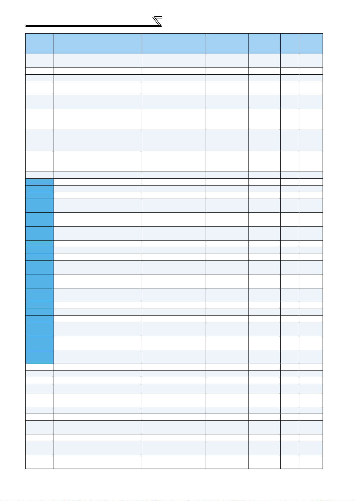
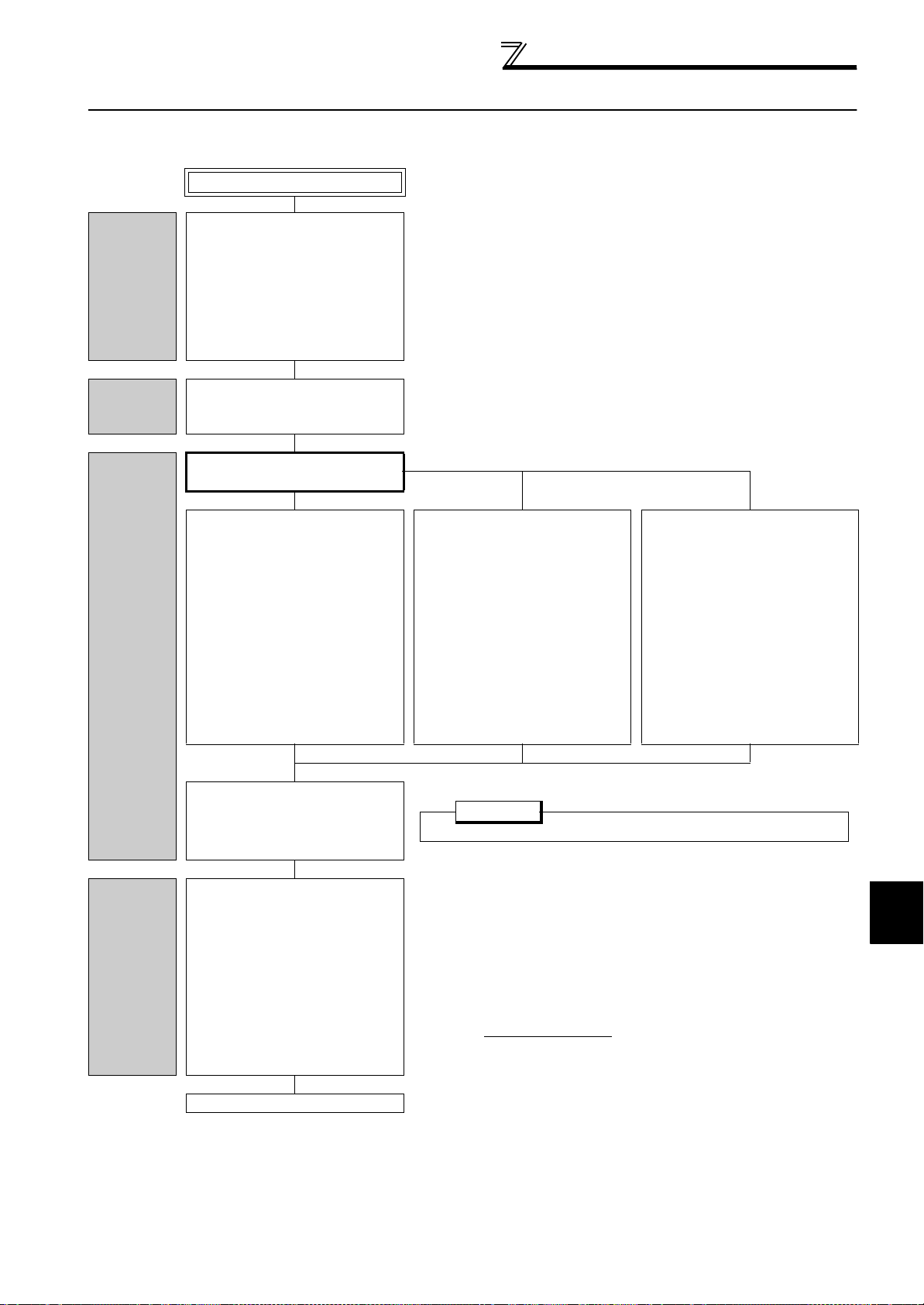
3 DANCER CONTROL/WINDING DIAMETER
COMPENSATION
3.1 Dedicated specification list
Item Description
PID control, PI control, P control, and PD control can be selected.
Gain switchover by dancer position is available. Gain switchover by external
terminal input is available.
Set a point with parameter.
Analog voltage 10V (terminal 1)
Available. Three patterns are selectable with external contact signal.
Calculation method by line speed detection and rotation speed of motor, and
calculation method by material thickness and rotation number of motor are
selectable.
Pulse train input (A/B phase, single phase) and analog input are selectable.
Available
Available. Four patterns are selectable with external signal.
Available. Straight movement (with three turns) against the roll diameter can be
performed.
Dancer/tension control selection, winding diameter compensation selection, PID
gain switchover, PID integral term reset (P control selection), speed
compensation gain selection, main speed acceleration/deceleration time
selection, winding diameter selection, winding diameter storage clear, winding/
unwinding selection.
Upper limit signal, lower limit signal, dancer roll position signal, signal loss
detection, initial winding diameter calculation completion, target winding diameter
achieved, winding/unwinding completion.
Set point, measured value, deviation, main speed, winding diameter, line speed,
compensation speed, winding length.
Dancer control
Winding
diameter
compensation
Common
Control method
Dancer roll position setting
Dancer roll position detection
signal
Main speed acceleration/
deceleration function
Additional function Material break detection
Constant line speed control Available
Winding diameter calculator
Line speed detection
Gear ratio setting
Maximum winding diameter/
minimum winding diameter
setting
Speed control proportional
gain compensation
Winding diameter storage Available
Dedicated input signal
Dedicated output signal
Dedicated monitor
14
3
DANCER CONTROL/WINDING DIAMETER COMPENSATION
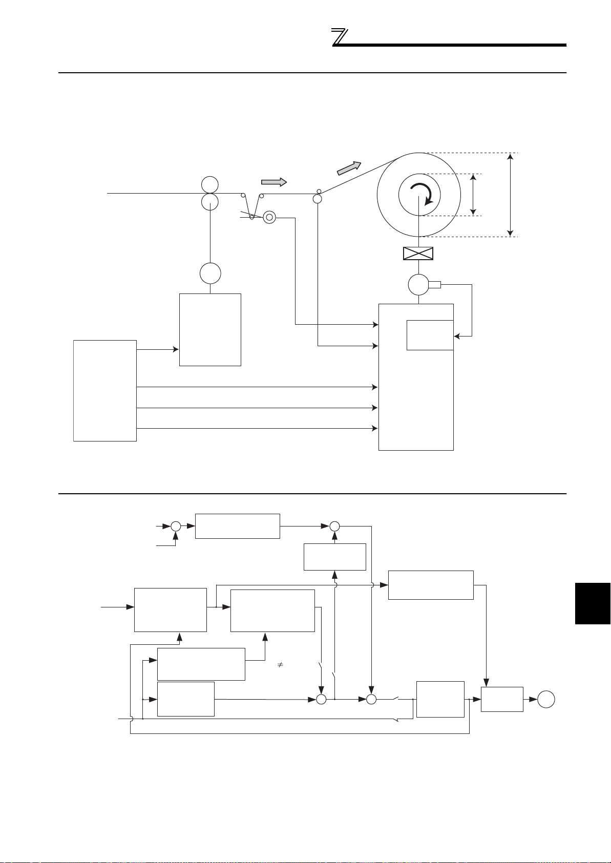
3.2 System configuration example
Vector Control
Dancer roll
(no-contact
potentiometer)
Dancer roll
position
(-10 to 10V)
Winding
IM
FR-A700
Encoder
IM
FR-A7AP
1
4
RL (X83)
Line speed *
Min.
diameter
Max. diameter
FR-A700-A1
2
Programmable
controller
Main speed setting
Line speed
STF/STR
Start signal
Dancer control selection (X83)
2
Feeder
Reduction gear
Line speed
detector
* Input line speed using line speed detector.
• Pr. 180 = "83"
• Pr. 762 = "0"
• Pr. 763 = "4"
• Pr. 267 = "1" or "2"
• Voltage/current input selection switch 1 = OFF
Winding diameter
calculation
X83-ON
X35
X83-OFF
Pr. 771 "9999"
Main speed
acceleration/
deceleration
Target line speed
calculation
Pr. 756, Pr. 757
PID calculation
Pr. 129, Pr. 130, Pr. 134
Winding diameter
Speed limit
+
+
+
+
X
IM
Line speed
Speed setting
Dancer roll position detection
Dancer roll set point
Pr. 133
-
+
Acceleration
/deceleration
processing
Pr. 7, Pr. 8
Speed
control
Speed control proportional
gain compensation
Main speed compensation
frequency calculation
based on winding diameter
Pr. 777 to Pr. 780
Speed
compensation gain
Pr. 706, Pr. 798
Pr. 773, Pr. 774
Pr. 720, Pr. 721,
Pr. 773, Pr. 774
Pr. 720, Pr. 721,
Pr. 773, Pr. 774
System configuration example
3.3 Control block diagram
15
Dedicated I/O signal
STF
X83
20ms or more
3.4 Dedicated I/O signal
3.4.1 Input signal list
Use contact input signals by assigning them to Pr. 178 to Pr. 189 (Input terminal function selection).
Pr. 178 to
Pr. 189
Typ e
setting
Dancer roll target position
Dancer roll position detection
Main speed setting
—
Analog/Pulse
Line speed detection
PID integral term reset
30
input
PID differential term
32
reset input
Offset displacement
33
storage
Integral term activation
34
signal
Speed compensation
35
gain
selection
Acceleration/
51
deceleration time
52 X52
selection
Minimum/maximum
53
winding diameter
54 X54
selection
Contact input
Stored winding diameter
55
clear
Winding/unwinding
56
selection
Dancer/tension control
83
function selection
Signal Description
— Set the target position with parameter. (Pr. 133) 27
Terminal 1
Terminal
2, etc.
Input dancer roll position detection signal. 29
Set the main speed which becomes the line speed. 43
Input detection signal of line speed. Input method can be selected from below.
Same as the main speed.
Pulse train input
—
(single-phase pulse from terminal JOG and FR-A7AL, encoder pulse* from
FR-A7AP/FR-A7AL)
Analog input (terminal 2, terminal 4)
* Encoder pulse train inputs are not available during vector control.
Turn ON X30 signal to reset integral term.
OFF: Does not reset integral term.
X30
ON: Resets integral term.
Integral term can be reset with MRS signal input when terminal is not assigned.
Turn ON X32 signal to reset differential term.
X32
OFF: Does not reset differential term.
ON: Resets differential term.
X33
Set an analog value, which is input to terminal 1, to
Turn X34 signal ON/OFF to enable/disable the control by integral term.
OFF: Disables integral term.
X34
ON: Enables integral term.
Integral term is enabled when X34 signal is not assigned.
Turn ON to select compensation by main rotation speed command.
OFF:Speed compensation gain does not change regardless of main speed.
X35
ON: Speed compensation gain changes with main speed.
Speed compensation gain changes with main speed when X35 signal is
not assigned.
X51
Acceleration/deceleration time of main speed can be switched. 46
X53
Select minimum/maximum winding diameter. 35
X55 Clears stored winding diameter calculation results. 37
X56 Select whether winding or unwinding shaft. 34
Select dancer control and winding diameter compensation function.
OFF: Normal operation.
ON:Activates dancer control and winding diameter compensation function.
Normal operation is performed when X83 signal is not assigned.
Always set when using dancer control and winding diameter
compensation function.
Turn ON/OFF the X83 in a stop status to switch between the dancer
control operation and normal operation. After turning ON the X83 signal,
X83
wait 20ms or longer to input a start command (STF/STR).
Pr. 751
as offset.
Refer
to
page
33
—
—
—
—
31
25, 32
16
Dedicated I/O signal
3
DANCER CONTROL/WINDING DIAMETER COMPENSATION
Pr. 178 to
Typ e
Pr. 189
Signal Description
setting
Select to enable/disable winding diameter compensation. When X84 is
Winding diameter
84
compensation selection
Dancer control
85
selection
Winding/unwinding
86
length clear
87
Contact input
Analog input gain
selection
88 X88
89
PID gain switchover
90 X90
ON, winding diameter compensation is disabled (winding diameter is
X84
retained), and only the dancer control operates.
(Input of X83 signal is necessary)
Select to enable/disable dancer control. When X85 signal is ON, dancer
X85
control is disabled, and only winding diameter compensation operates.
(Input of X83 signal is necessary)
X86 Clears measured winding/unwinding length. 42
X87
Changes the gain of analog input for main speed. 44
X89
PID gain can be switched with external terminal input. 29
Speed control
93
proportional gain
X93 Disables the settings of Pr. 777 to Pr. 780 (Speed control proportional gain). 47
disabled
3.4.2 Output signal list
Use output signals by assigning them to Pr. 190 to Pr. 196 (output terminal function selection).
Pr. 190 to Pr. 196
setting
Positive
Negative
logic
14 114 PID lower limit FDN
15 115
50 150
logic
PID upper limit FUP
Signal loss detection Y50 Output when dancer roll is in abnormal condition. 28
Winding diameter
51 151
52 152
53 153
54 154
calculation completion
Target winding diameter
Winding/unwinding
Dancer position
Signal Description
Output when dancer roll position goes lower than the setting in Pr. 132 PID
lower limit
Output when dancer roll position goes higher than the setting in Pr. 131
PID upper limit.
Output when winding diameter calculation is completed at an operation
Y51
at a start
achieved
completion
detection
start.
Output when winding diameter achieves the setting in Pr. 750 or becomes
longer for winding.
Y52
Output when winding diameter achieves the setting in Pr. 750 or becomes
shorter for unwinding.
Output when winding/unwinding length reaches the setting in Pr. 279 or
Y53
longer.
Output when dancer roll position is commanded, and the position of
Y54
dancer roll is within the set range of Pr. 702. This signal is also output when
inverter is at a stop.
Refer
to
page
25
32
Refer
to
page
29
29
41
48
42
27
17
Dedicated I/O signal
3.4.3 Analog input signals and pulse train input signals
Analog input
Function
Terminal 1
Pr. 868
Frequency (speed)
command
Frequency setting
auxiliary
Override 1
Magnetic flux command 1
Regenerative torque limit 2 2
Torque command 3, 4 3, 4
Stall prevention operation
level
Torque limit 4 4
Forward/reverse rotation
speed limit
Torque bias 6 6
10
0 1
4 4
5 5
Terminal 2
Terminal 4
Pr. 785
Terminal 6
(FR-A7AZ)
Pr. 406
Analog input
Function
Terminal 1 Terminal 2 Terminal 4
Dancer signal input selec-
tion
Pr. 731
Dancer main speed com-
mand input selection
Pr. 732
Line speed input selection
Pr. 763
Taper setting analog input
selection
Pr. 733
Dancer ten sion setting input
selection
Pr. 734
*1 Can be set when Pr. 291= "1, 11, 21, or 100".
*2 Setting Pr. 785 = "2" sets the taper ratio setting as the terminal 4 input regardless the Pr. 733 setting.
5346 27
5346
53461
534
5346 51
*2 6 51, 61
Terminal 6
FR-A7AZ
Single-phase pulse
train input
Terminal
JOG
FR-A7AL
Pr. 291
1, 11, 21,
100
: Setting available, : Setting not available
Single-phase pulse
train input
Terminal
JOG
1
*1
*1 7233
FR-A7AL
7243
Encoder
pulse train
input
FR-A7AP/
FR-A7AL
Encoder
pulse train
input
FR-A7AP/
FR-A7AL
: Setting not available
Refer to
page
Refer to the
Instruction
Manual
(Applied) of
FR-A700 series
Refer to
page
REMARKS
• While the dancer/tension control selection X83 signal is ON, the setting values of Pr. 731 to Pr. 734 and Pr. 763 have higher precedence
over the other assigned terminal settings such as Pr. 868, Pr. 785 = "1", and Pr. 406. (Example: When Pr. 731 = "5" and Pr. 868 = "0", the
terminal 1 is set to the dancer signal input.)
• For the taper setting analog input, the setting of Pr. 785 Terminal 4 function setting has higher precedence.
• While tension control is valid (Pr. 800 = "6 or 16"), the following parameter settings are invalid: Pr. 731 Dancer signal input selection,
Pr. 732 Dancer main speed command input selection, and Pr. 734 Dancer tension setting input selection.
• The dedicated-function parameters take the following precedence over each other. When several functions are assigned to a terminal,
input to the function of lower precedence is regarded as 0.
Terminal 4 function setting (Pr. 785 = "2") > Pr. 731 Dancer signal input selection > Pr. 763 Line speed input selection > Pr. 732 Dancer main speed
command input selection > Pr. 733 Taper setting analog input selection > Pr. 734 Dancer tension setting input selection.
18
Parameter setting procedure for dancer
3
DANCER CONTROL/WINDING DIAMETER COMPENSATION
POINT
Set X83 signal ON to activate dancer control.
*2 Maximum rotation number: max
Maximum number of rotation at the fastest line speed with minimum diameter
(maximum diameter) for winding (unwinding).
max =
V
max
r/min
Dmin (Dmax) Z
control function
3.5 Parameter setting procedure for dancer control function
The following flowchart shows the parameter setting example for the dancer control.
Start
Basic setting
Gain
adjustment of
speed control
Input signal
setting
Select control method according to
the application and the motor.
Applied motor selection (Pr. 71)
Motor capacity (Pr. 80)
Number of motor poles (Pr. 81)
Control method selection (Pr. 800)
Number of encoder pulses (Pr. 369)
Adjust gain of speed control.
Main speed setting
(Refer to page 43 )
Setting with analog input voltage
(terminal 2) *1
Set parameters below.
C2 Terminal 2 frequency setting bias
frequency = "0r/min"
Pr. 125 Terminal 2 frequency setting
gain frequency = "Maximum speed"
*2
C3 Terminal 2 frequency setting bias =
"0%"
C4 Terminal 2 frequency setting gain =
"100%"
Select any of V/F control, Advanced magnetic flux vector control, Real
sensorless vector control (speed control), or vector control (speed control) to
perform winding with dancer control.
Refer to page 22 for gain adjustment of speed control with Real sensorless
vector control/Vector control.
Setting with pulse train input
(terminal JOG)
Set parameters below according to
the input pulse frequency.
Pr. 384 Input pulse division scaling
"0"
factor
Pr. 385 Frequency for zero input pulse
= "0r/min"
Pr. 386 Frequency for maximum input
pulse = "Maximum speed"
Pr. 703 Minimum number of input
pulse = "0"
Pr.704 Maximum number of input pulse
= "Maximum number of pulses"
*1
Setting with digital input
(FR-A7AX)
Set parameters below according to
BCD and binary code signals.
Pr. 304 Digital input and analog input
compensation enable/disable selection
Pr. 300 BCD input bias
Pr. 301 BCD input gain
Pr. 302 BIN input bias
Pr. 303 BIN input gain
Pr. 305
Read timing operation selection
Pr. 329 Digital input unit selection
Assign X83 by setting "83" in any of
Input terminal function selection (Pr. 178
to Pr. 189).
Set action determined by polarity of
dancer roll position detection signal
Dancer
control
function
selection
(terminal 1 input
action selection
(Refer to page 25 )
Set Pr. 762 Winding/unwinding
selection. (Refer to page 34 )
For winding : Pr. 762 = "0"
For unwinding : Pr. 762 = "1"
*3) with Pr. 128 PID
See the next page.
Set Pr. 128 = "40" to accelerate when dancer roll position detection signal
(terminal 1 input
Set Pr. 128 = "41" to accelerate when dancer roll position detection signal
(terminal 1 input
*1 Use Pr. 732 to change the input terminal for the main speed commands.
*3 Use Pr. 731 to change the terminal for the dancer roll position detection.
*3) is negative.
*3) is positive.
19
Parameter setting procedure for dancer
Pr.133=
% at upper limit - % at lower limit
% at
lowest
2
POINT
Turn ON the start signal when
operation X83 is ON and main
speed = 0r/min, and move the
dancer roll up and down to
check compensation directions
of the dancer.
Pr. 763
setting
Line speed input signal
0
Without line speed input signal
(Main speed is the line speed.)
1 Single-phase pulse train input (terminal JOG)
2 Encoder pulse train input (FR-A7AP)
3 Analog Input (Terminal 2)
4 Analog Input (Terminal 4)
5 Analog Input (Terminal 1)
6 Analog Input (FR-A7AZ Terminal 6)
7 Single-phase pulse train input (FR-A7AL)
control function
Continued from the last page.
Acce
leration/
Deceleration
time setting
Target dancer
position
(Pr. 133)
setting
Operation
check
Set acceleration/deceleration time as
below.
(Refer to page 46)
Pr. 7 Acceleration time = "0s"
Pr. 8 Deceleration time = "0s"
Pr.
756 First acceleration time for main
= "Acceleration time of the line"
speed
Pr.757 First deceleration time for main
speed
= "Deceleration time of the line
Set Pr. 52 ="27" (monitor voltage % of
terminal 1 input).
And record,
Value when the dancer position is
at the upper limit
Value when the dancer position is
at the lower limit
Set the value obtained from
Alternatively, move the dancer roll to
the center position, and set the
monitored value of terminal 1 input
voltage % to Pr. 133.
Adjust the gain of dancer control (PID
control). (Refer to page 24 )
"
Pr. 756, Pr. 757:
When cushion time is considered in main speed command, set 0s.
Upper limit %
Target position
of
dancer roll
(Pr. 133)
Lower limit %
Refer to page 24 for gain adjustment of dancer control (PID control).
Dancer roll
upper limit
Dancer roll
lower limit
Compensation by winding
diameter calculation
(Winding/
Unwinding shafts)
Winding
diameter
calculator
setting
20
Gear ratio
setting
Set Pr. 763 Line speed input selection.
(Refer to page 33 )
Set gear ratio with Pr. 773 Gear ratio
numerator (driver side), Pr. 774 Gear
ratio denominator (follower side) when
a reduction gear is installed between
rolling shaft and motor output shaft.
(Refer to page 34 )
See next page
Perform winding
diameter
compensation
(Intermediate shafts)
Do not perform
winding diameter
compensation
Set
Pr. 771
r-r' limit value (diameter)
"9999" to inactivate winding diameter
calculator.
(Refer to page 38)
=
Test r un
3
DANCER CONTROL/WINDING DIAMETER COMPENSATION
Continued from the last page.
Input method for line speed
Parameter setting procedure for dancer
control function
Line speed
input
calibration
Winding
diameter
compensation
setting
Analog input
When Pr. 763 = "3,
4, 5 or 6"
For Pr. 765 Voltage reference for line
speed input, set an analog voltage
which is input to the inverter when the
line speed reaches the set speed in
Pr. 766.
(Refer to page 33)
Calibrate the line speed for the line
input signal according to the input
method of the line speed.
Set winding diameters.
Pr. 720 Maximum winding diameter 1 =
"Maximum diameter"
Pr. 721 Minimum winding diameter 1 =
"Minimum diameter"
(Refer to page 35)
Set a sampling time for the winding
diameter calculation.
Pr. 707 Sampling time for winding
diameter calculation = "0.01 to 1s"
Pr. 786 Number of averaging for winding
diameter calculation = "4"
(Refer to page 38)
Pulse train input
When Pr. 763 = "1, 2 or 7"
For Pr. 764 Pulse reference for line speed
input, set a pulse frequency which is
input when the line speed reaches the
set speed in Pr. 766.
(Refer to page 33)
Set a reference value for the line feeding speed in Pr. 766
Line speed reference. (Refer to page 33 )
Enter the same setting unit as Pr. 766 in Pr. 767 Line speed
unit . (Refer to page 33 )
Extend the sampling time and
increase the averaging count to
reduce fluctuation of winding diameter
compensation.
Without line
speed input signal
When Pr. 763= "0"
Set the maximum magnitude of value
obtained from winding diameter
calculation per sampling.
Set Pr. 771 r-r' limit value (diameter)
according to the material rolled up.
(Refer to page 38)
Test r un
REMARKS
If winding diameter compensation does not operate at low-speed operation, check the setting of Pr. 797 Rotation speed at winding diameter
calculated value activation (initial value is 3Hz).
21
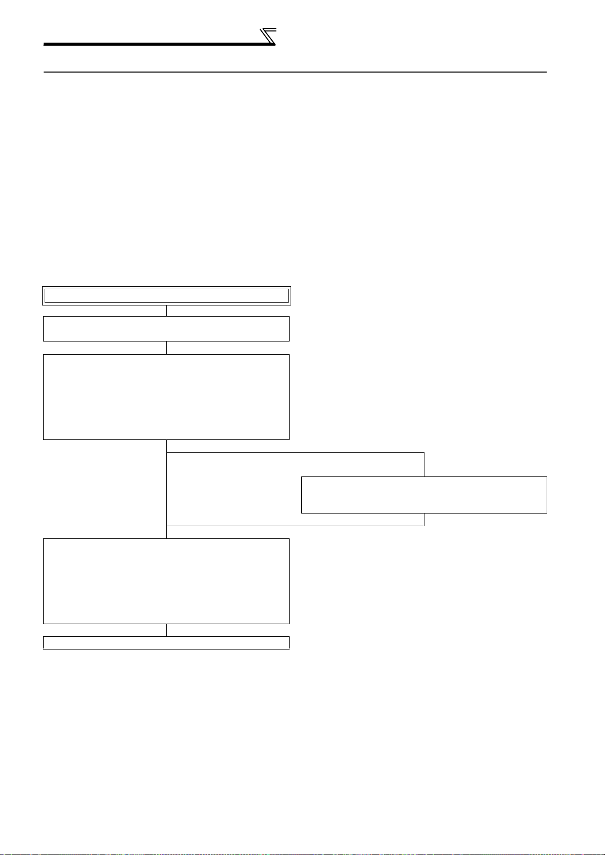
Gain adjustment in actual operation
3.6 Gain adjustment in actual operation
Prepare rolls of minimum, medium, and maximum diameters. (If a roll of medium diameter is not available, obtain P/I gain by
calculation.)
Adjust
• Speed control "P" gain, speed control "I" gain (Real sensorless vector control/Vector control)
• Dancer "PID" gain
3.6.1 Speed control P/I gain adjustment (Real sensorless vector control/Vector control)
Set "P" gain as high as possible without setting "I" gain as a basic principle so that inverter acting as a proportional amplifier
returns high response to the command from dancer roll.
Before sending material, adjust dancer roll by applying load to each spool shaft.
At this time, at least make adjustment with maximum diameter roll and minimum diameter roll.
Speed control P/I gain adjustment flowchart
Start
Set "0" in Pr. 821 Speed control integral time 1.
(Initial value is 0.333s)
Adjustment with the minimum-diameter roll
Increase Pr. 820 Speed control P gain 1 by 10% increments, and
adjust the gain to "the value of setting right before vibration/noise
is produced" "0.8 to 0.9" throughout minimum speed to
maximum speed.
Make a memo of the setting (A) in Pr. 820 Speed control P gain 1 at
this time.
Adjustment with the maximum-diameter roll
Increase Pr. 820 Speed control P gain 1 by 10% increments, and
adjust the gain to "the setting right before vibration/noise is
produced" "0.8 to 0.9" throughout minimum speed to maximum
speed.
Make a memo of the setting (B) in Pr. 820 Speed control P gain 1 at
this time.
See the next page.
Maximum-diameter roll is not
available
Perform "Dancer PID gain adjustment" (refer to page 24), and wind
to the maximum diameter while adjusting Pr. 820 Speed control P
gain 1.
22
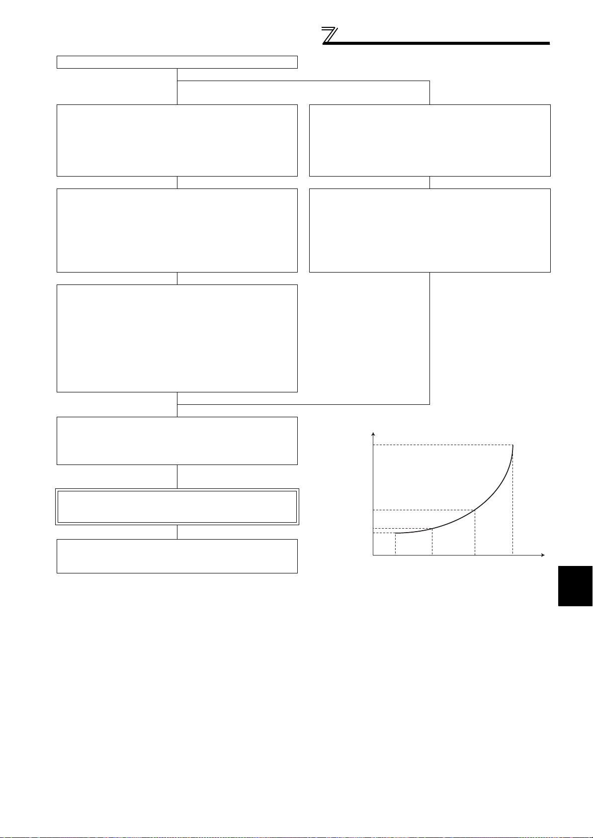
3
DANCER CONTROL/WINDING DIAMETER COMPENSATION
Continued from the last page.
P
P
P
P
Pr. 778 = /5 + Pr. 777
Pr.779 = 8 /15 + Pr. 777
However,
= Pr. 780 - Pr. 777
Gain adjustment in actual operation
Medium diameter roll is
available.
Adjustment at medium diameter roll 1
Increase Pr. 820 Speed control P gain 1 by 10% increments, and
adjust the gain to "the setting before vibration/noise is produced"
"0.8 to 0.9" throughout minimum speed to maximum speed.
Make a memo of the setting (C) in Pr. 820 Speed control P gain 1 at
this time.
Adjustment at medium diameter roll 2
Increase Pr. 820 Speed control P gain 1 by 10% increments, and
adjust the gain to "the value of setting before vibration/noise is
produced" "0.8 to 0.9" throughout minimum speed to maximum
speed.
Make a memo of the setting (D) in Pr. 820 Speed control P gain 1 at
this time.
Set medium diameters.
Medium diameter roll 1
Pr. 775 Speed control proportion term applied diameter 1
= (Medium diameter roll 1 - minimum diameter)
/(Maximum diameter - minimum diameter) 100 (%)
Medium diameter roll 2
Pr. 776 Speed control proportion term applied diameter 2
= (Medium diameter roll 2 - minimum diameter)
/(Maximum diameter - minimum diameter) 100 (%)
Medium diameter roll is not
available.
Obtain the setting(C) for Pr. 778 from the formula below.
Obtain the setting(D) for Pr. 779 from the formula below.
Refer to the memos you made, and set "A" to Pr. 777 Speed control
proportional gain 1, "C" to Pr. 778 Speed control proportional gain 2,
"D" to Pr. 779 Speed control proportional gain 3, and "B" to Pr. 780
Speed control proportional gain 4.
Speed control P/I gain adjustment
completed
Continue to dancer control PID gain
adjustment (page 24)
Calculation to obtain Pr. 778 and Pr. 779
r. 780
r. 779
r. 778
r. 777
Min. diameter Max. diameterX
1
X
2
23
 Loading...