

Mitsubishi Electric FR-A700, FR-A700-560K-79, FR-A700-355K-79 Installation Manuallines

INVERTER
FR-A700
INSTALLATION GUIDELINE
FR-A770-355K, 560K-79
Thank you for choosing this Mitsubishi Inverter.
Please read through this Installation Guideline enclosed to operate this inverter correctly.
Do not use this product until you have a full knowledge of the equipment, safety information and
instructions.
Please forward this Installation Guideline to the end user.
If you are going to utilize functions and performance, refer to the FR-A700 Instruction Manual (Applied) [IB0600226ENG].
CONTENTS
INSTALLATION OF THE INVERTER AND INSTRUCTIONS................. 1
1
SPECIFICATIONS................................................................................... 3
2
WIRING.................................................................................................... 8
3
PRECAUTIONS FOR USE OF THE INVERTER................................... 15
4
FAILSAFE OF THE SYSTEM WHICH USES THE INVERTER ............ 17
5
PARAMETER LIST................................................................................ 18
6
FR-A770 DEDICATED SPECIFICATIONS ........................................... 25
7
TROUBLESHOOTING........................................................................... 35
8
700
This section is specifically about safety matters
WARNING
CAUTION
CAUTION
WARNING
CAUTION
CAUTION
CAUTION
Environment
Surrounding
air
temperature
Pr.570 = "2"
(Initial value)
-10°C to +50°C (non-freezing)
Pr.570 = "102" -10°C to +40°C (non-freezing)
Ambient humidity 90% RH or less (non-condensing)
Storage temperature -20°C to +65°C
*1
Atmosphere
Indoors (free from corrosive gas,
flammable gas, oil mist, dust and dirt)
Altitude, vibration
Maximum 1000m above sea level for
standard operation. After that derate by
3% for every extra 500m up to 2500m
(91%). 2.9m/s
2
or less at 10 to 55Hz
(directions of X, Y, Z axes)
*1 Temperature applicable for a short time, e.g. in transit.
Do not attempt to install, operate, maintain or inspect the inve rter
until you have read through this Installation Gu ideline and
appended documents careful ly and can use the equipment
correctly. Do not use the inverter until you h ave a full knowledge
of the equipment, safety inform ation and instructions. In this
Installation Guideline, the safety instruction level s are classified
into "WARNING" and "CAUTION".
The level may even lead to a ser ious consequence
according to conditions. Both ins truction levels must be followed
because these are imp ortant to personal safety.
1. Electric Shoc k Prevention
While the inverter power is ON, do not open the front cover or
the wiring cover. Do not run th e inverter with the fron t cover or
the wiring cover removed. O therwise you may access the
exposed high voltage terminal s or the charging part of the
circuitry and get an elec tric shock.
Even if power is OFF, do not remove the front cover except for
wiring or periodic inspection. You may accidentally touch the
charged inverter circ uits and get an electric shock.
Before wiring, inspection or switching EMC filter ON/OFF
connector, power must be switched OFF. To confirm that, LED
indication of the operat ion panel must be checked. (It m ust be
OFF.) Any person who is involved in wiring, inspection or
switching EMC filter ON/OFF connec tor shall wait for at least
10 minutes after the power supply has bee n switched OFF and
check that there are no residual voltage using a tester or the
like. The capacitor is c harged with high voltage for som e time
after power OFF, and it is dangerous.
This inverter must be earthed (grounded). Earthing (grounding)
must conform to t he requirements of national and local safety
regulations and elec trical code (NEC sectio n 250, IEC 536
class 1 and other app licable standards).
A neutral-point earthe d (grounded) power sup ply for 400V
class inverter in comp liance with EN standard mus t be used.
Any person who is invol ved in wiring or inspection of this
equipment shall be full y competent to do the work.
The inverter must be installed before wiring. Otherwise you
may get an electric sho ck or be injured.
Setting dial and key operations must be performed with dry
hands to prevent an electric shock. Otherwise you may get an
electric shock.
Do not subject the cables to scratches, excessive stress,
heavy loads or pin ching. Otherwise you may get an electric
shock.
Do not replace the cool ing fan while power is ON. It is
dangerous to replace the cooling fan while power is ON.
Do not touch the printed circ uit board or handle the cables with
wet hands. Otherwise y ou may get an electric shock.
When measuring the mai n circuit capacitor capacity (Pr.259
Main circuit capacitor life measuring = "1"), the DC voltage is
applied to the motor for 1s at powe ring OFF. Never touch the
motor terminal, etc. ri ght after powering OFF to preven t an
electric shock.
A-1
Incorrect handling may ca use hazardous
condition s, resulting in death o r severe
injury.
Incorrect handling may ca use hazardous
conditions, resulting in medium or slight
injury, or may cause only material damage.
2. Fire Prevention
Inverter must be installed on a nonflammable wall without holes
(so that nobody touches the inverter heatsink on the rear side,
etc.). Mounting it to or near flammable material can cause a fire.
If the inverter has become faulty, the inverter power must be
switched OFF. A continuous flow of large current could cause a fire.
When using a brak e resistor, a sequence that will turn OFF
power when a fault signa l is output must be configur ed.
Otherwise the brak e resistor may overheat d ue to damage of
the brake transistor and possibly cause a fire.
Do not connect a resistor directly to the DC terminals P/+ and
N/-. Doing so could c ause a fire.
Daily and periodic inspections must be performed as instructed
in the Instruction Manual. If the product is used without receiving
any inspection, it may cause a burst, break, or fire.
3. Injury Prevention
The voltage applied to eac h terminal must be the ones
specified in the Instruction Manu al. Otherwise burst, damage,
etc. may occur.
The cables must be connected to the correct terminals.
Otherwise burst, damage, etc. may occur.
Polarity must be correct. Otherwi se burst, damage, etc. may
occur.
While power is ON or for some time after power -OFF, do not
touch the inverter since the inverte r will be extremely hot.
Doing so can cause burns.
4. Additional Instructions
Also the following points must be noted to prevent an accidental failure,
injury, electric shock, etc.
(1) Transportation and installation
The product must be transported in correct method that
corresponds to the weight. Failure to do so may lead to injuries.
Do not stack the boxes contai ning inverters higher than the
number recommended.
The product must be installe d to the position where withstands
the weight of the product according to the information in the
Instruct ion Manual.
Do not install or oper ate the inverter if it is damaged o r has
parts missing. This can res ult in breakdowns.
When carrying the inverter, do not hold it by the front cover or
setting dial; it may fa ll off or fail.
Do not stand or rest h eavy objects on the product .
The inverter mo unting orientation must be co rrect.
Foreign conduc tive objects must be preven ted from entering
the inverter. That includes screws and metal frag ments or
other flammable su bstance such as oil.
As the inverter is a prec ision instrument, do not drop or s ubject
it to impact.
The inverter must b e used under the following e nvironment:
Otherwise the inverter may be damaged.
If halogen-base d materials (fluorine, chlo rine, bromine, iodine,
etc.) infiltrate into a M itsubishi product, the product wi ll be
damaged. Halogen-ba sed materials are often inc luded in
fumigant, which is used to sterilize or disinfest wooden
packages. When packa ging, prevent residual fu migant
components from being infiltrated into Mitsubishi products, or
use an alternative steri lization or disinfection metho d (heat
disinfection, etc.) f or packaging. Sterilization of disinfection o f
wooden package shou ld also be performed b efore packaging
the product.
(2) Wiri ng
CAUTION
CAUTION
WARNING
CAUTION
CAUTION
CAUTION
CAUTION
Do not install a power factor correctio n capacitor, surge
suppressor or capacitor type filter on the inve rter output side.
These devices on the inverter output side may be overheated
or burn out.
The connection orientati on of the output cables U, V, W to the
motor affects the rotation direc tion of the motor.
(3) Test operat ion and adj ustment
Before starting operation, ea ch parameter must be confirmed
and adjusted. A failure to do so may cause some machines to
make unexpected mo tions.
(4) Operat ion
Any person must stay away from the equipment when the retry
function is set as it will res tart suddenly after trip.
Since pres sing key may not stop output depen ding on
the function setting s tatus, separate circuit and switch that
make an emergency stop (power OFF, mechanical brake
operation for emergen cy stop, etc.) must be prov ided.
OFF status of the start s ignal must be confirmed befor e
resetting the inverter fault . Resetting inverter alarm with the
start signal ON restarts the m otor suddenly.
The inverter must be u sed for three-phase inducti on motors.
Connection of any other el ectrical equipment to the inve rter
output may damage the equipment.
Performing pre-exci tation (LX signal and X13 signal) under
torque control (Real se nsorless vector control) ma y start the
motor running at a low speed even when the start comm and
(STF or STR) is not input. The motor may al so run at a low
speed when the speed limit value = 0 with a s tart command
input. It must be confirme d that the motor running will not
cause any safety probl em before performing pre-ex citation.
Do not modify the equi pment.
Do not perform parts remova l which is not instructed in thi s
manual. Doing so may lead to fault or damage of the inverter.
(5) Emergency stop
A safety backup s uch as an emergency brake must be
provided to prevent hazar dous condition to the machine and
equipment in case of i nverter failure.
When the break er on the inverter input side trips, the wiring
must be checked for fault (short circuit), and internal parts of
the inverter for a damage, etc. The c ause of the trip must be
identified and removed before turning ON the power of the
breaker.
When any protectiv e function is activated, appropriate
corrective action m ust be taken, and the inverter mu st be reset
before resuming oper ation.
(6) Maintenance, inspection and parts replacement
Do not carry out a megger (insulation resistance) test on the
control circuit of the inverter. It will cause a failure.
(7) Disposing of the inverter
The inverter must be treated as industrial waste.
General instructions
Many of the diagrams and drawings in this Installation Gui deline
show the inverter without a cover or partially open for
explanation. Never ope rate the inverter in this m anner. The
cover must be always r einstalled and the instructi on in this
Installation Guideline must be followed when operating the
inverter.
The electronic therma l relay function does not guar antee
Do not use a magnetic con tactor on the inverter input for
The effect of electromag netic interference must be r educed by
Appropriate measures must be taken to suppress harmonics.
When parameter cle ar or all parameter c lear is performed, the
The inverter can be ea sily set for high-speed operatio n. Before
Stop status cannot be hold by the inverter's brake function. In
Before running an i nverter which had been stored for a long
Static electricity in your body must be disch arged before you
protection of the moto r from overheating. It is reco mmended to
install both an external ther mal and PTC thermistor for
overheat protection.
frequent starting/stoppi ng of the inverter. Otherwise the life of
the inverter decrease s.
using a noise filter o r by other means. Other wise nearby
electronic equipmen t may be affected.
Otherwise power s upply harmonics from the inverter may heat/
damage the power fact or correction capacitor and ge nerator.
required parameters mu st be set again before s tarting
operations because all parameters return to the initial value.
changing its setting, th e performances of the moto r and
machine must be fully examined.
addition to the inverter's brak e function, a holding device must
be installed to ensure saf ety.
period, inspection and te st operation must be perfor med.
touch the product. Othe rwise the product may be d amaged.
A-2
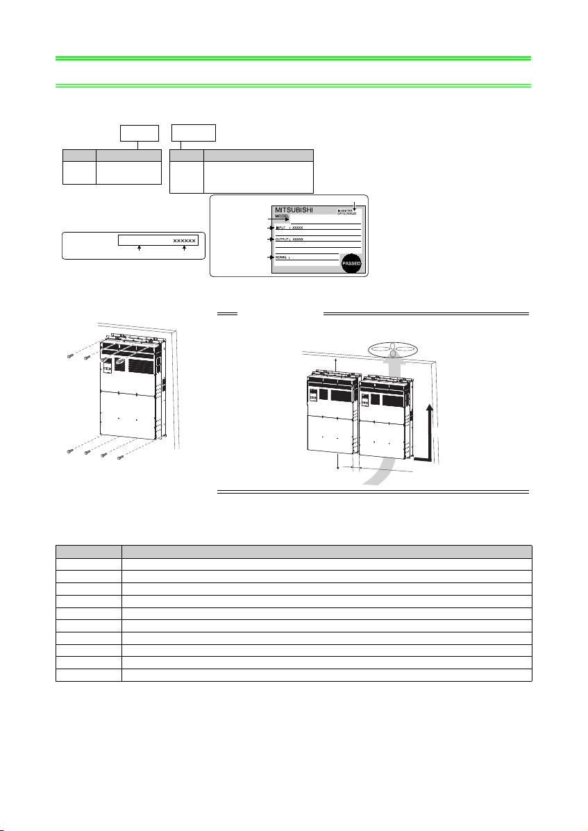
INSTALLATION OF THE INVERTER
Capacity plate
Inverter model
Serial number
Capacity plate
Rating plate
- 79
FR-A770-355K-79
355K
Symbol
355K,
560K
Displays
the inverter capacity [kW]
Model number
FR --A770
Symbol
A770
Voltage class
Three-phase
690V class
• Inverter Model
Rating plate
Inverter model
Input rating
Output rating
Serial number
FR-A770-355K-79
Production year and month
CAUTION
• When encasing multiple inverters, install them in parallel as a cooling measure.
• Install the inverter vertically.
10c
mor
mo
r
e
20cm or more
20cm or more
Vertical
AND INSTRUCTIONS
1
INSTALLATION OF THE INVERTER AND INSTRUCTIONS
• Installation of the inverter
Installation on the enclosure
• Compatible plug-in options
The options compatible with the FR-A770-79 are as shown below.
Model Function
FR-A7AX 16-bit digital input function
FR-A7AY Analog output function, Digital output function
FR-A7AR Relay output function
FR-A7AP Encoder feedback control, Vector control
FR-A7AL Orientation control, Encoder feedback control, Vector control, Position control, Encoder pulse division output
FR-A7AZ Bipolar analog output function, High-resolution analog input function, Motor thermistor interface
FR-A7NC CC-Link communication function
FR-A7NCE CC-Link IE Field Network communication function
FR-A7ND DeviceNet communication function
FR-A7NP Profibus-DP communication function
1
INVERTER AND INSTRUCTIONS
5cm 5cm
5cm
Measurement
position
Measurement
position
Inverter
MCCB INV
MCCB INV
IM
IM
INSTALLATION OF THE
• General precaution
The bus capacitor discharge time is 10 minutes. Before starting wiring or inspection, switch power OFF, wait for
more than 10 minutes, and check for residual voltage between terminal P/+ and N/- with a meter etc., to avoid a
hazard of electrical shock.
• Environment
Before installation, check that the environment meets following specifications.
Surrounding air
temperature
Pr.570 = "2" (Initial value):
-10°C to +50°C (non-freezing)
Pr.570 = "102":
-10°C to +40°C (non-freezing)
Ambient humidity
Storage tempera ture
Ambience
Altitude, vibration
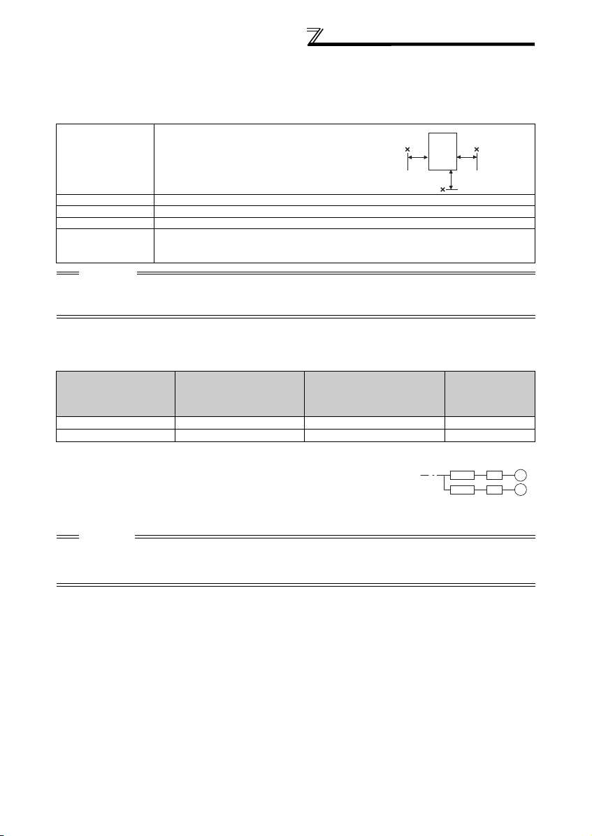
CAUTION
• Install the inverter on a strong surface securely and vertically with bolts.
• Leave enough clearance and take cooling measures.
• Avoid places where the inverter is subjected to direct sunlight, high temperature and high humidity.
• Install the inverter on a non-flammable wall surface.
• Peripheral devices
90%RH or less (non-condensing)
-20°C to +65°C
Indoors (No corrosive and flammable gases, oil mist, dust and dirt.)
Maximum 1000m above sea level for standard operation. After that derate by 3% for every extra
500m up to 2500m (91%).
2.9m/s2 or less at 10 to 55Hz (directions of X, Y, Z axes)
Check the inverter model of the inverter you purchased. Appropriate peripheral devices must be selected according
to the capacity. Refer to the following list and prepare appropriate peripheral devices:
Moulded Case Circuit Breaker
*2
or Earth Leakage
Motor Output (kW)
*1 Motor Output (kW) in the above table indicates values when using the 4-pole standard motor with power supply voltage of 690VAC 60Hz.
*2 Select the MCCB according to the power supply capacity. Install one MCCB per inverter.
*3 Magnetic contactor is selected based on the AC-3 class. The electrical durability of magnetic contactor is 500,000 times. When the
magnetic contactor is used for emergency stop during motor driving, the electrical durability is 25 times.
CAUTION
When the inverter capacity is larger than the motor capacity, select an MCCB and a magnetic contactor according to the
inverter model and cable and reactor according to the motor output.
When the breaker on the inverter primary side trips, check for the wiring fault (short circuit), damage to internal parts of the
inverter, etc. Identify the cause of the trip, then remove the cause and power on the breaker.
*1
Applicable Inverter Model
355 FR-A770-355K-79 500A 401A
560 FR-A770-560K-79 800A 611A
(MCCB)
Circuit Breaker (ELB)
(NF or NV type)
Input Side
Magnetic
Contactor
*3
2

SPECIFICATIONS
2
2 SPECIFICATIONS
2.1 Inverter rating
Model FR-A770-K-79 355 560
Pr.570 = "2"
Applicable motor capacity (kW) *4
Rated current (A)
Output
Power supply
Power supply voltage for control circuit *5 AC 380 to 480V 50/60Hz
Protective structure (JEM 1030) Open type (IP00)
*1 The % value of the overload current rating indicated is the ratio of the overload current to the inverter's rated output current. For repeated
duty, allow time for the inverter and motor to return to or below the temperatures under 100% load.
*2 The maximum output voltage dose not exceed the power supply voltage. The maximum output voltage can be changed within the setting
range. However, the pulse voltage value of the inverter output side voltage remains unchanged at about that of the power supply.
*3 The power supply capacity varies with the value of the power supply side inverter impedance (including those of the input reactor and cables).
*4 The applicable motor capacity indicated assumes that the output voltage is 660 to 690V.
*5 When connecting the control circuit separately from the main circuit power supply.
*6 Set Pr.570 = "102" for Vector control or Real sensorless vector control.
Overload current rating *1 150% 60s (inverse-time characteristics)
Rated voltage *2 Three-phase 600 to 690V
Output frequency range 0.2 to 400Hz
PWM carrier frequency 2kHz
Rated input AC voltage/frequency Three-phase 600 to 690V 50/60Hz
Permissible AC voltage fluctuation ±10%
Permissible frequency fluctuation ±5%
Power supply capacity (kVA) *3 463 730
Cooling system Forced air cooling
Approx.mass (kg) 380
(Initial value)
Pr.570 = "102" *6 315 500
Pr.570 = "2"
(Initial value)
Pr.570 = "102" *6 344 545
355 560
401 611
3
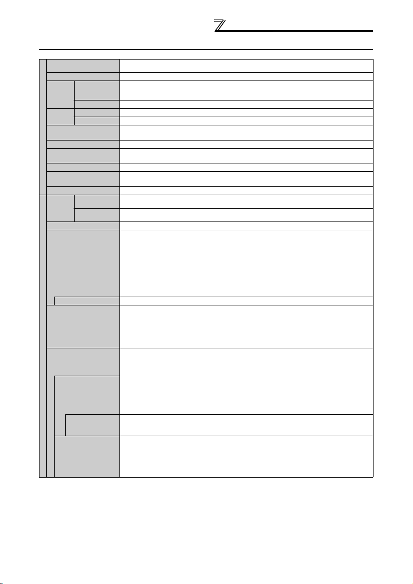
2.2 Common specifications
SPECIFICATIONS
Control method
Output frequency range
Frequency
Analog input
setting
resolution
Digital input
Analog input
Frequency
accuracy
Digital input
Voltage/frequency
characteristics
Torque boost
Control specifications
Acceleration/deceler ation
time setting
DC injection brake
Stall prevention operation
level
Torque limit level
Analog input
Frequency
setting
signal
Digital input
Start signal
Input signals
(twelve te rminals)
Pulse train input
Operational functions
Output signals
Open collector output
Operation specificatio ns
(5 terminals)
Relay output (2 terminals )
Operating status
When used with the
FR-A7AY, FR-A7AR
(option)
For meter
Analog output
(Max. 10VDC: one
terminal)
(Max. 20mADC: one
terminal)
High carrier frequency PWM control (V/F control, Advanced magnetic flux vector control and Real sensorless vector
control are available) / vector control
0.2 to 400Hz (The maximum frequency is 120Hz under Real sensorless vector control and vector control *1.)
0.015Hz/60Hz (terminal 2, 4: 0 to 10V/12bit)
0.03Hz/60Hz (terminal 2, 4: 0 to 5V/11bit, 0 to 20mA/about 11bit, terminal 1: 0 to ±10V/12bit)
0.06Hz/60Hz (terminal 1: 0 to ±5V/11bit)
0.01Hz
Within ±0.2% of the max. output frequency (25°C±10°C)
Within 0.01% of the set output frequency
Base frequency can be set from 0 to 400Hz Constant torque/variable torque pattern or adjustable 5 points V/F can be
selected
Manual torque boost
0 to 3600s (acceleration and deceleration can be set individually), linear or S-pattern acceleration/deceleration mode,
backlash measures acceleration/deceleration mode are available.
Operation frequency (0 to 120Hz), operation time (0 to 10s), operation voltage (0 to 30%) can be changed
Operation current level can be set (0 to 220% adjustable), whether to use the function or not can be selected
Torque limit value can be set (0 to 220% variable)
Terminal 2, 4: 0 to 10V, 0 to 5V, 4 to 20mA (0 to 20mA) can be selected
Terminal 1: -10 to +10V, -5 to +5V can be selected
Input using the setting dial of the operation panel or parameter unit
Four-digit BCD or 16-bit binary (when used with option FR-A7AX)
Forward and reverse rotation or start signal automatic self-holding input (3-wire input) can be selected.
The following signals can be assigned to
remote setting, stop-on-contact, second function selection, third function selection, terminal 4 input selection, JOG
operation selection, selection of automatic restart after instantaneous power failure, flying start, external thermal relay
input, PU operation/external inter lock signal, external DC injection brake operation start, PID control enable terminal,
brake opening completion signal, PU operation/External operation switchover, load pattern selection forward rotation
reverse rotation boost, V/F switchover, load torque high-speed frequency, S-pattern acceleration/deceleration C
switchover, pre-excitation, output stop, start self-holding selection, control mode switchover, torque limit selection,
start-time tuning start external input, torque bias selection 1, 2
reverse rotation command, inverter reset, PTC thermistor input, PID forward reverse operation switchover, PU-NET
operation switchover, NET-External operation switchover, command source switchover, simple position pulse train
sign, simple position droop pulse clear, magnetic flux decay output shutoff.
100kpps
Maximum/minimum frequency setting, frequency jump operation, external thermal relay input selection, polarity
reversible operation, automatic restart after instantaneous power failure operation, electronic bypass operation,
forward/reverse rotation prevention, remote setting, brake sequence, second function, third function, multi-speed
operation, stop-on-contact control, load torque high speed frequency control, droop control, regeneration avoidance,
slip compensation, operation mode selection, offline auto tuning function, online auto tuning function, PID control,
computer link operation (RS-485), motor end orientation
machine analyzer
The following signals can be assigned to Pr. 190 to Pr. 196 (output terminal function selection): inverter running, inverter
running/start command on, up-to-frequency, instantaneous power failure/undervoltage, overload warning, output
frequency (speed) detection, second output frequency (speed) detection, third output frequency (speed) detection,
electronic thermal relay function pre-alarm, PU operation mode, output current detection, zero current detection, PID
lower limit, PID upper limit, PID forward rotation reverse rotation output, electronic bypass MC1, electronic bypass
MC2, electronic bypass MC3, orientation complete
heatsink overheat pre-alarm, PID control activated, motor temperature detection
interruption, inverter operation ready, life alarm, power savings average value update timing, current average monitor,
fault output 1, 2, 3 (power-off signal), maintenance timer alarm, remote output, forward rotation output
rotation output
in-position completion
In addition to above, the following signal can be assigned to Pr.313 to Pr. 319 (extension output terminal function
selection): control circuit capacitor life, main circuit capacitor life, cooling fan life, inrush current limit circuit life. (only
positive logic can be set for extension terminals of the FR-A7AR)
The following signals can be assigned to
(analog output )
speed, motor torque, converter output voltage (steady or peak value), electronic thermal relay function load factor,
input power, output power, load meter, motor excitation current, reference voltage output, motor load factor,
saving effect, PID set point, PID measured value, motor output, torque command, torque current command, and
torque monitor, PLC function output.
*1, easy gain tuning, speed feed forward, and torque bias *1
*1, low speed detection, torque detection, regenerative status output *1, start-time tuning completion,
*1, alarm output and fault output.
: output frequency, motor current (steady or peak value), output voltage, frequency setting, operation
*1
Pr. 178 to Pr. 189 (input terminal function selection)
*1
, P/PI control switchover, forward rotation command,
*1, machine end orientation *2, pre-excitation, notch filter,
*1, orientation fault *1, brake opening request, fan fault output,
Pr. 54 CA terminal fun ction selection
and
: multi speed selection,
*3, during retry, PID output
*1, reverse
Pr. 158 AM terminal fun ction selection
power
4
SPECIFICATIONS
*1 Available only when the option (FR-A7AP/FR-A7 AL) is mounted.
*2 Available only when the option (FR-A7AL) is mounte d.
*3 Available only when the option (FR-A7AZ) is mounte d.
*4 Available only when the option (FR-A7AD) is mounted.
*5 Can be displayed only on the oper ation panel (FR-DU07).
*6 Can be displayed only on the paramete r unit (FR-PU07).
*7 Temperature applicable for a short period in transit, etc.
*8 This protective function is not availab le in the initial status.
*9 Set Pr.570 = "102" for Vector control or Real sens orless vector control.
Operation
Operating status
panel
(FR-DU07)
Parameter
Indication
unit
Fault reco rd
(FR-PU07)
Interactive
guidance
Protective/
warning
function
Environment
Protective
function
Warning function
Pr.570 = "2"
Surroundi ng
(Initial value)
air
temperature
Pr.570 = "102" *9
Ambient humidity
Storage temperature *7
Atmosphere
Altitude/vibration
The following operating status can be displayed: Output frequency, motor current (steady or peak value), output
voltage, frequency setting, running speed, motor torque, overload, converter output voltage (steady or peak value),
electronic thermal relay function load factor, input power, output power, load meter, motor excitation current, position
pulse, cumulative energization time, orientation status
energy saving effect, cumulative saving power, PID set point, PID measured value, PID deviation, inverter I/O
terminal monitor, input terminal option monitor
assignment status
temperature
Fault definition is displayed when a fault occurs, the output voltage/current/frequency/cumulative energization time
right before the fault occurs and past 8 fault records are stored.
Function (help) for operation guide *6
Overcurrent during acceleration, overcurrent during constant speed, overcurrent during deceleration, overvoltage
during acceleration, overvoltage during constant speed, overvoltage during deceleration, inverter protection thermal
operation, motor protection thermal operation, heatsink overheat, instantaneous power failure occurrence,
undervoltage, input phase loss
main circuit element overheat, output phase loss, external thermal relay operation
option fault, parameter error, PU disconnection, retry count excess
circuit, 24VDC power output short circuit, output current detection value excess
communication fault (inverter), USB fault, opposite rotation deceleration fault
large
fault
*8,
Fan fault, overcurrent stall prevention, overvoltage stall prevention, electronic thermal relay function pre-alarm, PU
stop, maintenance timer alarm
parameter copy alarm, speed limit indication
-10°C to +50°C (non-freezing)
-10°C to +40°C (non-freezing)
90%RH maximum (non-condensing)
-20°C to +65°C
Indoors (without corrosive gas, flammable gas, oil mist, dust and dirt etc.)
Maximum 1000m above sea level for standard operation. After that derate by 3% for every extra 500m up to 2500m
(91%). 2.9m/s
*6, torque command, torque current command, feed back pulse *1, motor output, motor
*3
*8, motor overload, output side earth (ground) fault overcurrent, output short circuit,
*1*8, overspeed *8, position error large *1*8, encoder phase error *1*8, signal loss detection *1*8, brake sequence
*8, parameter write error, copy operation error, operation panel lock, password locked,
2
or less at 10 to 55Hz (directions of X, Y, Z axes)
*1, actual operation time, motor load factor, cumulative power,
*5, output terminal option monitor *5, option fitting status *6, terminal
*8, CPU fault, operation panel power supply short
*8, PTC thermistor operation *8,
*8, inrush current limit circuit fault,
*8, analog input fault, speed deviation
5
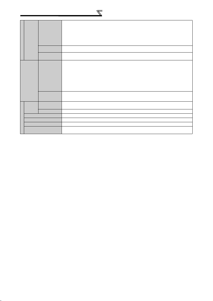
2.3 Outline dimension drawing
• FR-A770-355K, 560K-79
4-φ12 hole
15
1550
SPECIFICATIONS
1580
185
R/L1
S/L2
995
T/L3 P1
N/- P/+
300300300
UW
V
15
222 194
440
(Unit:mm)
4.54.5
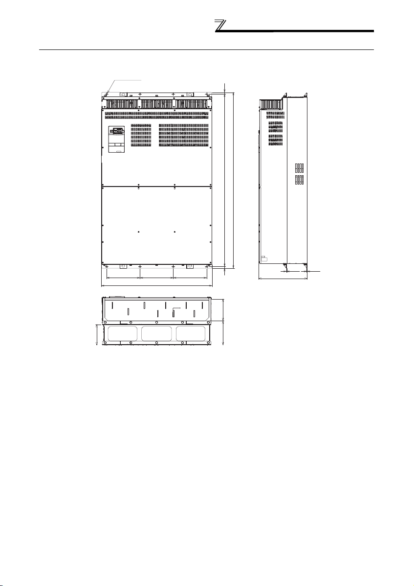
6
SPECIFICATIONS
P1
P1
Rating plate
4.5
405 10
445 10
450 10
390 max
Earth (ground) terminal
215 2
150 1
230 max
2-M12 eye nut
(2-φ30 hole)
(for M12 screw)
4-mounting hole
(for M10 screw)
P
P
2-terminal (for M16 bolt)
*1
*1 Remove the eye nut after installation of the product.
(Unit:mm)
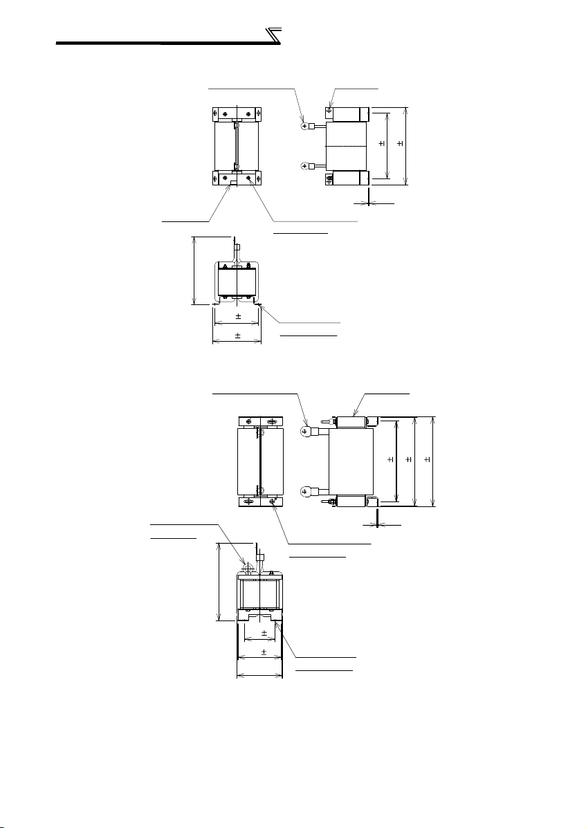
• FR-HEL-N355K
2-terminal (for M12 bolt)
2-φ20 hole
• FR-HEL-N560K
Rating plate
360 max
P1
P
215 1.5
240 2.5
P1
P
Earth (ground) terminal
(for M8 screw)
4-mounting hole
(for M10 screw)
324 5
4.5
(Unit:mm)
384 5
7

Terminal connection diagram
(Refer to the Instruction
Manual (Applied))
(Refer to the
Instruction Manual
(Applied))
(Refer to the
Instruction Manual
(Applied))
(Refer to the Instruction
Manual (Applied))
3 WIRING
3.1 Terminal connection diagram
Source logic
Main circuit terminal
Control circuit terminal
Three-phase AC
power supply
Control input signals (No voltage input allowed)
Terminal functions vary with
the input terminal
assignment (Pr. 178 to Pr. 189)
*3.JOG terminal can be used
as pulse train input terminal.
Use Pr. 291 to select
JOG/pulse.
*4. AU terminal can be
used as PTC input
terminal.
Selection of automatic restart
Frequency setting signal (Analog)
Frequency setting
potentiometer
*
Terminal input specifications
5.
can be changed by analog
input specifications
switchover (Pr. 73, Pr. 267).
Set the voltage/current input
switch in the OFF position to
select voltage input (0 to 5V/0
to10V) and ON to select
current input (4 to 20mA).
*6
. It is recommended to use 2W1k
when the frequency setting signal
is changed frequently.
CAUTION
· To prevent a malfunction due to noise, keep the signal cables more than 10cm away from the power cables. Also separate the main circuit wire of the
input side and the output side.
· After wiring, wire offcuts must not be left in the inverter.
Wire offcuts can cause an alarm, failure or malfunction. Always keep the inverter clean.
When drilling mounting holes in an enclosure etc., take care not to allow chips and other foreign matter to enter the inverter.
· Set the voltage/current input switch correctly. Different setting may cause a fault, failure or malfunction.
*1. DC reactor (FR-HEL)
Be sure to connect the DC
reactor supplied.
MCCB
Jumper
*2. To supply power to the
control circuit separately,
remove the jumper across
R1/L11 and S1/L21.
Forward
rotation
start
Reverse
rotation
start
Start self-
holding selection
Multi-speed
selection
High speed
Middle
speed
Low speed
Jog operation
Second function selection
Output stop
Reset
Terminal 4 input selection
(Current input selection)
after instantaneous
power failure
Contact input common
1/2W1k
*6
24VDC power supply
(Common for external power supply transistor)
3
2
1
(+)
Auxiliary
input
(-)
Terminal
(+)
4 input
(-)
(Current
input)
MC
*2
Earth
(Ground)
Connector
for plug-in option
connection
R/L1
S/L2
T/L3
T
R1/L11
S1/L21
STF
STR
STOP
RH
RM
RL
JOG
RT
MRS
RES
AU
PTC
CS
SD
PC
10E(+10V)
10(+5V)
0 to 5VDC
2
0 to 10VDC
0 to 20mADC
5
(Analog common)
0 to
1
0 to ±5VDC
4 to 20mADC
4
0 to 5VDC
0 to 10VDC
Option connector 1
Option connector 2
Option connector 3
*1
Earth
(Ground)
P1 P/+
Inrush
current
limit
circuit
Main circuit
Control circuit
*3
*4
AU
SINK
SOURCE
24V
*5
Voltage/current
input switch
2
4
ON
OFF
(Initial value)
selectable
*5
(Initial value)
±
10VDC
selectable
*5
(Initial value)
*5
selectable
N/-
C1
B1
A1
C2
B2
A2
RUN
SU
IPF
OL
FU
SE
PU
connector
CA
AM
TXD+
TXD-
RXD+
RXD-
Terminating
VCC
resistor
U
V
W
Relay output 1
(Fault output)
Relay output 2
Running
Open collector output
Up to frequency
Instantaneous
power failure
Overload
Frequency detection
Open collector output common
Sink
/
source common
(+)
(-)
(+)
5
(-)
Data transmission
Data reception
SG
GND
5V
Motor
IM
Earth (Ground)
Relay output
Terminal functions
vary with the output
terminal assignment
(Pr. 195, Pr. 196)
Terminal functions
vary with the output
terminal assignment
(Pr. 190 to Pr. 194)
Analog current output
(0 to 20mADC)
Analog signal output
(0 to 10VDC)
RS-485 terminals
(Permissible load
current 100mA)
8
WIRING
IM
R/L1 S/L2 T/L3
N/-
R1/L11 S1/L21
P/+
P/+
Jumper
Charge lamp
Motor
Power supply
DC reactor
3.2 Main circuit terminal
(1) Main circuit terminal specifications
Termi nal
Symbol
R/L1,
S/L2,
T/L3
U, V, W Inverter output Connect a three-phase squirrel-cage motor.
R1/L11,
S1/L21
P/+, P1
P/+, N/-
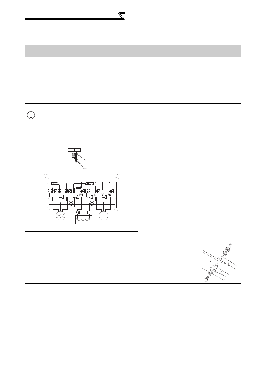
(2) Terminal layout and wiring
FR-A770-355K, 560K-79
Terminal Name Description
AC power input Connect to the commercial power supp ly.
Power supply for
control circu it
DC reactor
connection
-------------------- Non-connection
Earth (Ground) For earthing (grounding) the inverter chassis. Must be earthed (grounded).
Connected to the AC power supply terminals R/L1 and S/L2. To retain the fault display
and fault output, remove the jumpers across terminals R/L1 and R1/L11 and across S/
L2 and S1/L21 , and apply ext ernal power supply of 380 to 480VAC to these terminals.
Connect the DC re actor.
CAUTION
· The power supply cables must be connected to R/L1, S/L2, T/L3. (Phase sequence needs not to be
matched.) Never connect the power cable to the U, V, W of the inverter. Doing so will damage the
inverter.
· Connect the motor to U, V, W. At this time, turning ON the forward rotation switch (signal) rotates the
motor in the counterclockwise direction when viewed from the motor shaft.
· When wiring the inverter main circuit conductor, tighten a nut from the right side of the conductor.
When wiring two wires, place wires on both sides of the conductor. (Refer to the drawing on the right.)
For wiring, use bolts (nuts) provided with the inverter.
9

WIRING
3 × wire resistance[mΩ/m] × wiring distance[m] × current[A]
1000
(3) Applicable cable size
Select the recommended cable size to ensure that a voltage drop will be 2% max.
If the wiring distance is long between the inverter and motor, a main circuit cable voltage drop will cause the motor
torque to decrease especially at the output of a low frequency.
The following table indicates a selection example for the wiring length of 20m.
690V class
*2
Tightening
Torque
N·m
Applicable
Inverter Model
FR-A770-355K-79 M12(M10) 46 200-12 200-12 325-12 150-10 200 200 250 150
FR-A770-560K-79 M12(M10) 46 150-12 150-12 200-12 200-10 2 150 2150 2200 200
*1 The recommended cable size is that of the cable (LMFC (heat resistant flexible cross-linked polyethylene insulated cable) etc.) with continuous
maximum permissible temperature of 90°C. Assumes that the surrounding air temperature is 50°Cor less and wiring is performed in an
enclosure.
*2 The terminal screw size indica tes the terminal si ze for R/L1, S/L2 , T/L3, U, V, W, PR, PX, P/+, N/-, P1 , and a screw for earthing (grounding).
Ter min al
Screw Size
R/L1,
S/L2,
T/L3
Crimping Terminal
U, V, W P/+, P1
Earth
(Ground)
Cable
The line voltage drop can be calculated by the following formula:
Line voltage drop [V]=
Use a larger diameter cable when the wiring distance is long or when it is desired to decrease the voltage drop (torque
reduction) in the low speed range.
CAUTION
· Tighten the terminal screw to the specified torque.
A screw that has been tighten too loosely can cause a short circuit or malfunction.
A screw that has been tighten too tightly can cause a short circuit or malfunction due to the unit breakage.
· Use crimping terminals with insulation sleeve to wire the power supply and motor.
(4) Total wiring length
Connect one or more motors within a total wiring length of 500m.
(The wiring length should be 100m maximum for vector control.)
When driving a 690V class motor by the inverter, surge voltages attributable to the wiring constants may occur at the
motor terminals, deteriorating the insulation of the motor.
Take the following measure in this case.
Use a "690V class inverter-driven insulation-enhanc ed motor"
(5) Cable size of the control circuit power supply (terminal R1/L11, S1/L21)
· Terminal screw size: M4
· Cable size: 0.75mm
· Tightening torque: 1.5N·m
2
to 2mm
2
Cable Size (mm2) *1
R/L1,
S/L2,
U, V, W P/+, P1
T/L3
Earth
(Ground)
Cable
10
 Loading...