

Mitsubishi Electric FR-A5NPA Instruction Manual

C
MIT
SUBIS
C
FR-A5NPA
Frequency Inverter
Instruction Manual
HI ELECTRI
Art. no.: 146529
01 02 2003
Version B
IB(NA)-0600095-B
Profibus/DP
Communication Option
MITSUBISHI ELECTRI
INDUSTRIAL AUTOMATION
Thank you for choosing the Mitsubishi transistorized inverter option unit.
This instruction manual gives handling information and precautions for use of
this equipment. Incorrect handling might cause an unexpected fault. Before using
the equipment, please read this manual carefully to use the equipment to its
optimum.
This section is specifically about safety matters
Do not attempt to install, operate, maintain or inspect this product until you
have read through this instruction manual and appended documents carefully
and can use the equipment correctly. Do not use this product until you have a
full knowledge of the equipment, safety information and instructions.
In this instruction manual, the safety instruction levels are classified into
"WARNING" and "CAUTION".
WARNING
CAUTION
Note that the CAUTION level may lead t o a serious consequence according to
conditions. Please follow the instructions of both levels because they are
important to personnel safety.
Assumes that incorrect handling may cause
hazardous conditions, resulting in death or
severe injury.
Assumes that incorrect handling may cause
hazardous conditions, resulting in medium or
slight injury, or may cause physical damage only.
SAFETY INSTRUCTIONS
1. Electric Shock Prevention
WARNING
While power is on or when the inverter is running, do not open the front
••••
cover. You may get an electric shock.
Do not run the inverter with the front cover removed . Otherwise, you may
••••
access the exposed high-voltage terminals and charging part and get an
electric shock.
If power is off, do not remove the front cover except for wiring or periodic
••••
inspection. You may access the charged inverter circuits and get an electric
shock.
Before starting wiring or inspection, switch power off, wait for more than 10
••••
minutes, and check for no residual voltage with a tester or the like.
WARNING
Any person who is involved in the wiring or inspection of this equipment
••••
should be fully competent to do the work.
Always install the option unit before wiring. Otherwise, you may get an
••••
electric shock or be injured.
Handle this option unit with dry hands to prevent an electric shock.
••••
Do not subject the cables to scratches, excessive stress, heavy loads or
••••
pinching. Otherwise, you may get an electric shock.
While power is on, do not move the station number and baud rate setting
••••
switches. Doing so can cause an electric shock.
A-1
2. Injury Prevention
C
C
C
C
C
C
AUTION
•••• Apply only the voltage specified in the instruction manual to each terminal to
prevent burst, damage, etc.
•••• Ensure that the cables are connected to the correct terminals. Otherwise,
burst, damage, etc. may occur.
•••• Always make sure that polarity is correct to prevent burst, damage, etc.
•••• While power is on or for some time after power-off, do not touch the inverter
as it is hot and you may get burnt.
3. Additional instructions
Also note the following points to prevent an accidental failure, injury, electric
shock, etc.:
(1) Transportation and mounting
AUTION
•••• Do not install or operate the option unit if it is dama ge d or ha s part s missing.
•••• Do not stand or rest heavy objects on the product.
•••• Check that the mounti ng orientation is correct .
•••• Prevent screws, metal fragments or other conductive bodies or oil or other
flammable substance from entering the inverter.
(2) Test operation and adjustment
AUTION
•••• Before starting operation, confirm and adjust the parameters. A failure to do
so may cause some machines to make unexpected motions.
(3) Usage
WARNING
•••• Do not modify the equipm en t.
AUTION
•••• When parameter clear or all parameter clear is performed, each parameter
returns to the factory setting. Re-set the required parameters before starting
operation.
•••• For prevention of damage due to stati c electricity, touch nearby metal before
touching this product to eliminate static electricity from your body.
(4) Maintenance, inspection and parts replacement
AUTION
•••• Do not test the equipment with a megger (measure insulation resistance).
(5) Disposal
AUTION
•••• Treat as industrial waste.
(6) General instruction
All illustrations given in this manual may have been drawn with covers or safety
guards removed to provide in-depth description. Before starting operation of
the product, always return the covers and guards into original positions as
specified and operate the equipment in accordance with the manual.
A-2

CONTENTS
1. PRE-OPERATION INSTRUCTIONS 1
1.1 Unpacking and Product Confirmation...............................................1
1.2 Packing Confirmation........................................................................1
1.3 Structure...........................................................................................2
1.4 Inverter Specifications ......................................................................3
1.5 Communication Specification ...........................................................3
2. INSTALLATION 4
2.1 Pre-Installation Instructions ..............................................................4
2.2 Inverter Node Address Setting..........................................................4
2.3 Installation and Removal Procedure.................................................5
2.3.1 Profibus Communication Cable.................................................7
3. INVERTER SETTING 8
3.1 List of Dedicated Communication Parameters .................................8
3.2 Operation Mode................................................................................9
3.2.1 Operation mode indication.........................................................9
3.2.2 Operation mode switching .......................................................10
3.3 Operation and Speed Command Source........................................15
3.3.1 FR-A500/F500 series...............................................................15
3.3.2 FR-V500 series........................................................................17
3.4 Operation at Communication Error Occurrence .............................19
3.4.1 Operation selection at communication error occurrence (For the
3.4.2 Alarm and measures................................................................23
3.4.3 Inverter reset............................................................................24
3.5 Instructions .....................................................................................24
FR-A500/V500 series only)......................................................19
4. FUNCTION OVERVIEW 25
4.1 Function Overview..........................................................................25
4.1.1 Input from master module to inverter.......................................26
4.1.2 Output from inverter to master module....................................27
5. Profibus PROFILES 28
5.1 Profibus Device Data......................................................................28
5.2 Slave User Parameter ....................................................................30
5.3 Profibus Profiles..............................................................................31
5.3.1 ID definitions............................................................................31

5.3.2 Buffer memory map.................................................................32
5.3.3 Points to note...........................................................................32
6. BUFFER MEMORY DETAILS 33
6.1 FR-A500/F500 Series.....................................................................33
6.2 FR-V500 Series..............................................................................40
7. PARAMETER DEFINITIONS - A500/F500 SERIES 47
7.1 Outline of PNU................................................................................47
7.2 Profibus PNU..................................................................................48
7.2.1 Real-time monitor ....................................................................48
7.2.2 Parameter clear.......................................................................50
7.2.3 Operation mode read/write ......................................................50
7.2.4 Set frequency read ..................................................................50
7.2.5 Terminal input read..................................................................50
7.2.6 Inverter reset............................................................................50
7.2.7 Node address read ..................................................................51
7.2.8 Alarm history............................................................................51
7.2.9 PNU list read............................................................................52
7.3 Standard Parameters.....................................................................53
8. PARAMETER DEFINITIONS - V500 SERIES 56
8.1 Outline of PNU................................................................................56
8.2 Profibus PNU..................................................................................57
8.2.1 Real-time monitor ....................................................................57
8.2.2 Parameter clear.......................................................................59
8.2.3 Operation mode read/write ......................................................59
8.2.4 Set frequency read ..................................................................59
8.2.5 Terminal input read..................................................................60
8.2.6 Inverter reset............................................................................60
8.2.7 Node address read ..................................................................60
8.2.8 Alarm history............................................................................61
8.2.9 PNU list read............................................................................62
8.3 Standard Parameters......................................................................63
9. TROUBLESHOOTING 66

1. PRE-OPERATION INSTRUCTIONS
1.1 Unpacking and Product Confirmation
Take the option unit out of the package, check the unit name, and confirm
that the product is as you ordered and intact.
Note that the FR-A500/F500 series inverter and FR-V500 series inverter
have different functions when the option is fitted.
Please check the SERIAL number of the inverter when using the FR-V500
series.
• SERIAL number check
•This product may be used with the FR-V500 series manufactured in and
after May 2002. Any of the models may be used with this unit if its
SERIAL number indicated on the rating plate and package has
"!25!!!!!!" or later version. For details on the SERIAL number,
please contact your sales representative.
SERIAL is made up of 1 version symbol, 1 alphabet letter or numeric
character indicating month, and 7 numeric characters indicating year
and control number as shown below. (Only the first three digits of the
control number are printed on the package.)
!
Symbol Year Month Control number
1.2 Packing Confirmation
Make sure that the package includes the following
" Instruction manual.........................................................................1
" Mounting screws M3 × 6...............................................................2
2 5 !!!!!!
SERIAL number
1
PRE-OPERATION INSTRUCTIONS
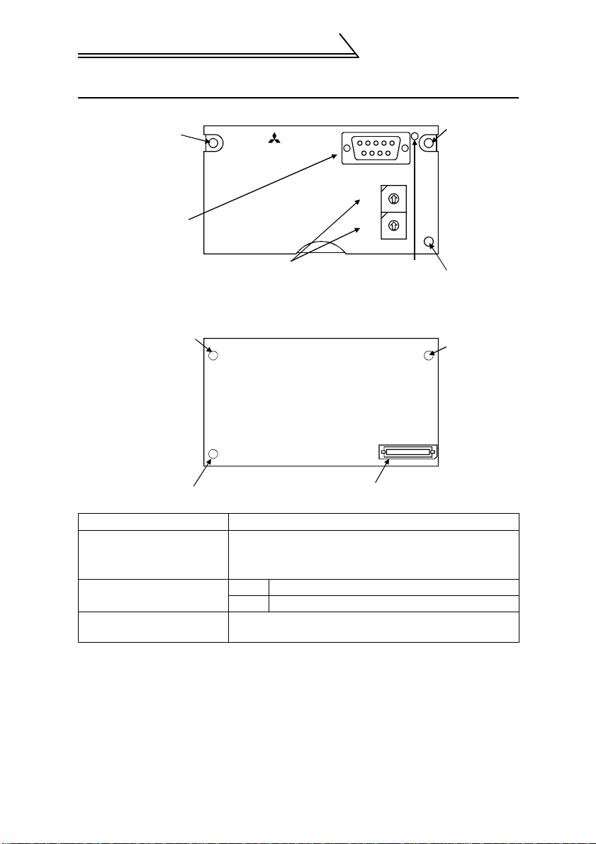
1.3 Structure
Mounting
hole
Profibus connector
(Dsub9 pin connector)
Node address switch Operating status
Mounting
hole
Option fixing hole
Name Function
Node address setting
switches
Operatin g st atus indica t or
LEDs (green)
Profibus connector
(Dsub9 pin connector )
Front view
FR-A5NPA
1
0
2
F
3
E
4
D
5
C
SW1
6
B
7
A
8
9
1
0
2
F
3
E
4
D
5
C
SW2
6
B
7
A
8
9
indicator LED
Mounting
hole
Option fixing hole
Rear view
Mounting
hole
connector
Used to set the inverter stat i on number between 0
and
7DH.
For details, refer to page 4.
off Communication stops
on During communicati on
Used to connect a Profibus cable for Profibus
communication (R efer to page 7.)
H
2

1.4 Inverter Specifications
PRE-OPERATION INSTRUCTIONS
Type
Number of node
occupied
Cable
When the option unit (FR -A5 N PA) is plugged in, the protective structure
*
(JEM1030) is open type (IP00).
Inverter inboard option, t o be connected with a connec to r
(can be mounted/dismounted to/from the inverter front face)
One inverter occupies one node.
For 12Mbps communi cati on
(compliant with EEIA-RS-48 5 st andard)
1.5 Communication Specification
Communication
speed
Wiring length 1200m
maximum
Wiring length 600m
maximum
Wiring length 200m
maximum
Wiring length 100m
maximum
9600bps, 19.2Kbps, 93. 75Kbps
187.5Kbps
500Kbps, 1.5Mbps
3Mbps, 6Mbps, 12Mb ps
3
2. INSTALLATION
2.1 Pre-Installation Instructions
Make sure that the input power of the inverter is off.
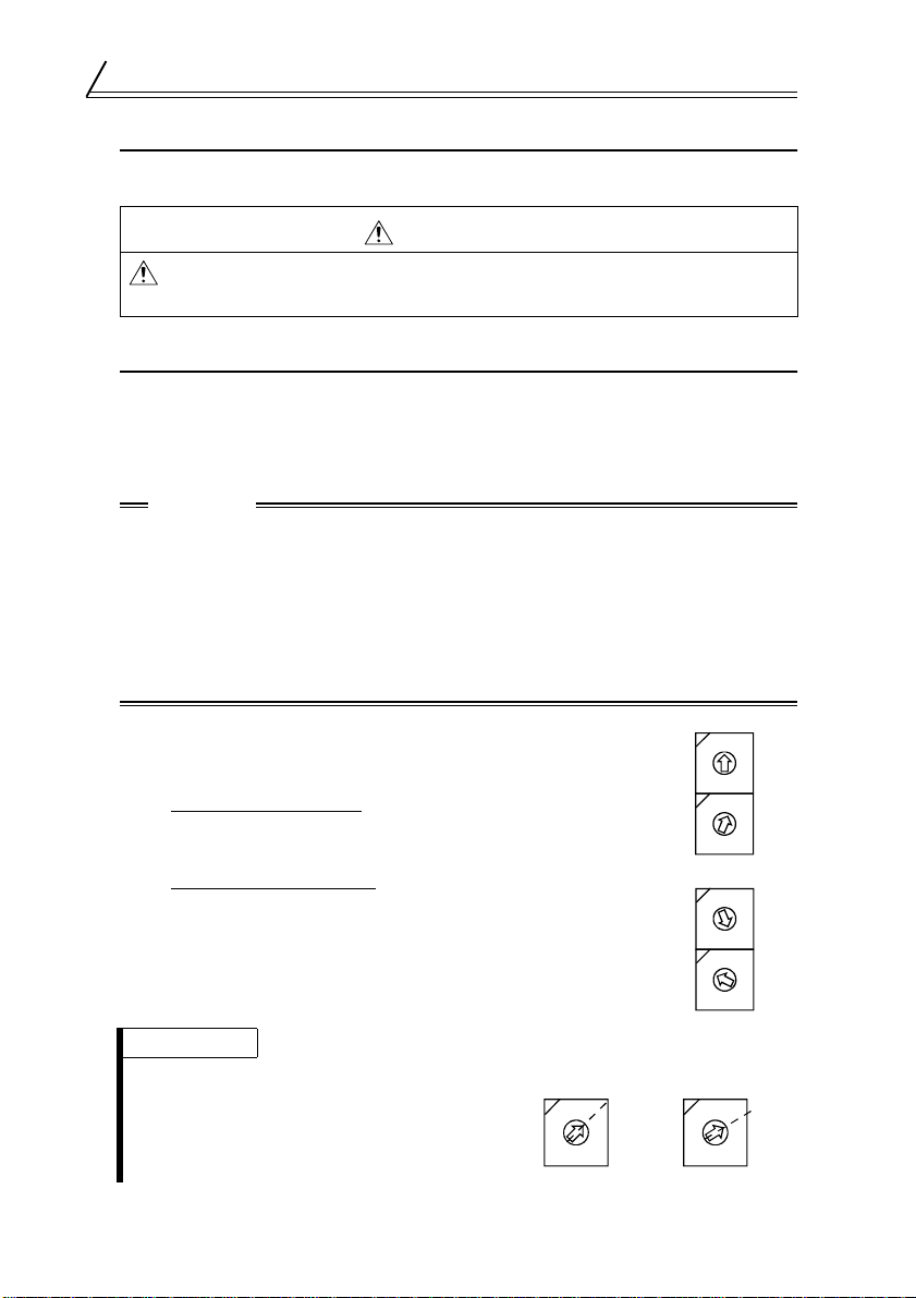
CAUTION
With input power on, do not install or remove the option unit.
Otherwise, the inverter and option unit may be damaged.
2.2 Inverter Node Address Setting
Set the node address of the inverter on the Profibus network.
Set the inverter node address before switching on the inverter and do not
change the setting while power is on.
The node address may be set between 0
CAUTION
1. Do not set the node address to 7E
2. Depending on the master module, 0
be used.
3. The node address changed while powering on the inverter is not
made valid. The node address setting is made valid either after
power is reapplied or when the RES signal turns on.
4. You cannot set the same node address to other devices on the
network. (Such setting disables normal communication.)
$ Set the arrow (%) of the corresponding switch to the
required numeral.
Example:
•For node address 1
:
H
Set (%) of SW1 to "0" and (%) of SW2 to "1".
H
and 7DH.
H
through FFH.
H
, 1H, 2H, 7CH, 7DH may not
SW1
SW2
1
0
2
F
3
E
4
D
5
C
6
B
7
A
8
9
1
0
F
2
3
E
4
D
5
C
6
B
7
A
8
9
•For node address 7D
:
H
Set (%) SW1 to "7" and the (%) SW2 to "D".
REMARKS
Set each node add ress switch to the
position of its numeral without error. If it is
set to any position between numerals,
normal data communication cannot be
made.
4
SW1
SW2
6
B
7
A
8
9
1
0
2
F
3
E
4
D
5
C
6
B
7
A
8
9
1
0
2
F
3
E
4
D
5
C
Bad exampleGood example
0
1
F
2
E
3
4
D
5
C
6
B
7
A
8
9
0
1
F
2
E
3
4
D
5
C
6
B
7
A
8
9
INSTALLATION
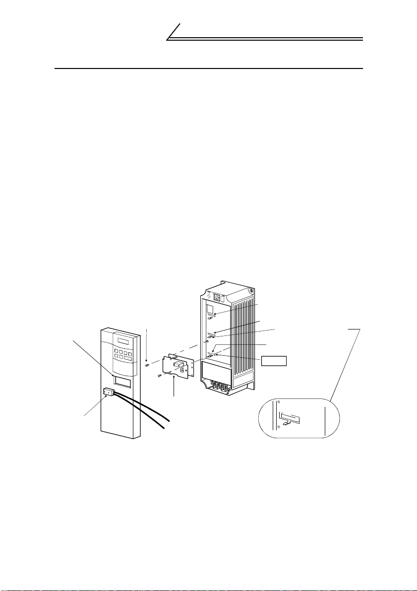
2.3 Installation and Removal Procedure
Mount the option unit to slot 3.
(1) Remove the front cover from the inverter and remove the DATA PORT
cover by pushing it from the back of the front cover.
(2) Securely insert the connector of the option unit far into the connector
of slot 3 in the inverter. At this time, fit the option fixing holes snugly.
For the position of slot 3, refer to the illustration below.
Also be sure to fit the unit into th e option fixing hook (For the FR-A500/
FR-F500 series, it is available in Aug., 2000).
(3) Securely fix the option unit to the inverter on both sides with the
accessory mounting screws. If the screw holes do not line up, the
connector may not have been plugged snugly. Check for loose
plugging.
(4) Reinstall the front cover of the inverter. (Refer to the inverter manual.)
(5) Connect a Profibus communication cable to the Profibus connector
(Dsub9 pin connector) of the option. (Refer to page 7 for a
communication cable.)
Inverter
(Without cover)
Slot 1
Accessory screw
(2 pcs.)
DATA PORT
Slot 2
Option fixing hook
Inverter side connector
Slot 3
Dsub9 pin
male
connector
Option unit
(FR-A5NPA)
Profibus communication
cable
The slots 1, 2, and 3 are provided
with an option fixing hook .
5

INSTALLATION
(6) To remove the option unit, remove the two left and right screws, and
then hold the option unit and pull its bottom toward you as shown in the
figure. (The option unit is fixed by the hook of the inverter.)
REMARKS
Perform wiring after the option unit (FR-A5NPA) was fitted and the inverter front
cover was mounted.
The option unit (FR-A5NPA) is valid only if it is fitted in slot 3.
When two or more co m m unication op t i on units are mou nted, "E.OPT" error is
displayed. Note that whe n th e r el ay output/computer link unit (FR- A5NR) is
mounted, only relay ou tp ut is act ivat ed.
6
INSTALLATION
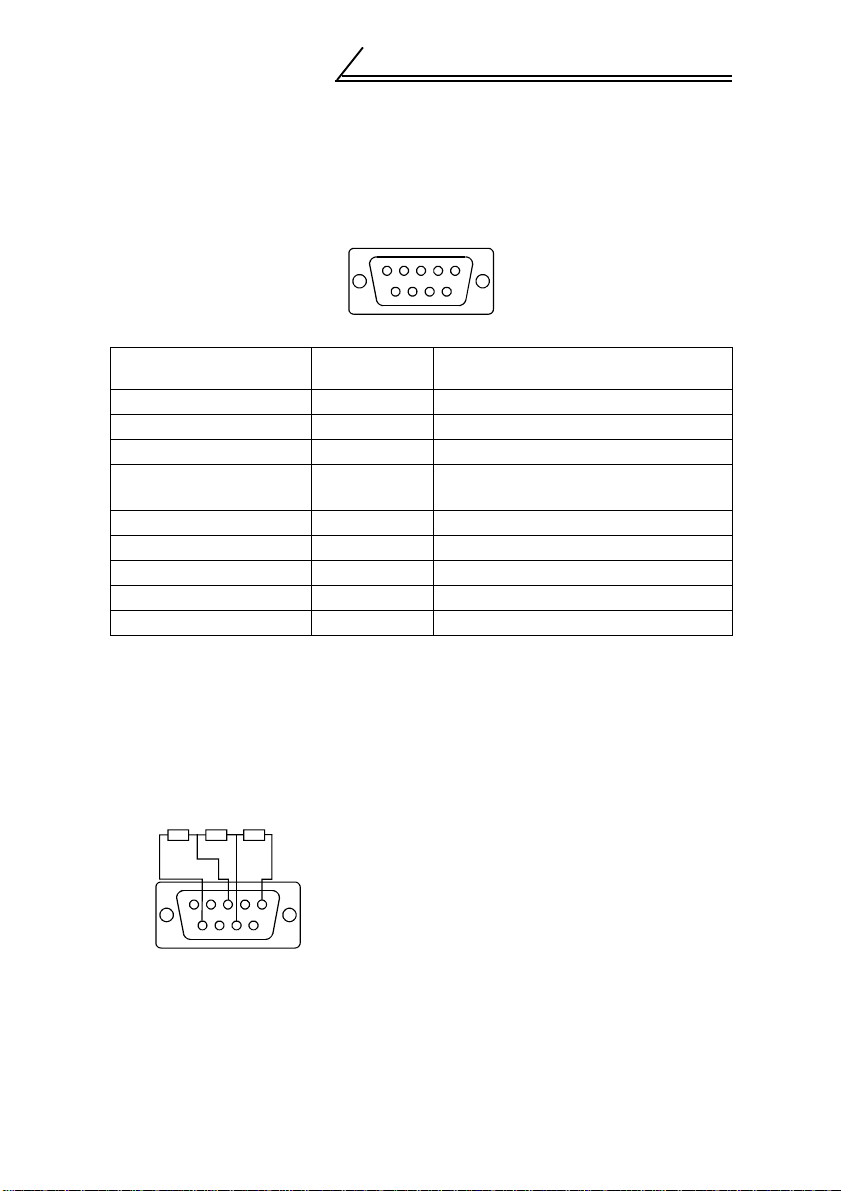
2.3.1 Profibus Communication Cable
Make a network communication cable using a Dsub9 pin male connector
and a cable supporting 12Mbps communication.
(1) Pin arrangement of a connector
12345
6789
Dsub9 pin type male
connector pin number
1 SHIELD Shield
2 N/C Unconnected
3 RxD/TxD+ Receive/transmit + dat a
4RTS *1
5 DGND *2 Data earth
6 +5VDC *2 Voltage output
7 N/C Unconnected
8 RxD/TxD- Receive/transmit - data
9 N/C Unconnected
*1 It may not be necessary depending on th e m aster module used.
*2 This signal is used to make the terminating r es is to r present.
Signal Application
Control signal (transm i ssion request
from the inverter)
(2) Terminating resistor
If the nodes at both ends of the network are the FR-A5NPA and
inverter, connect a connector with a built-in terminating resistor.
R1 R2 R3
12345
R1=390Ω±2% 1/4W
R2=220Ω±2% 1/4W
R3=390Ω±2% 1/4W
6789
7

3. INVERTER SETTING
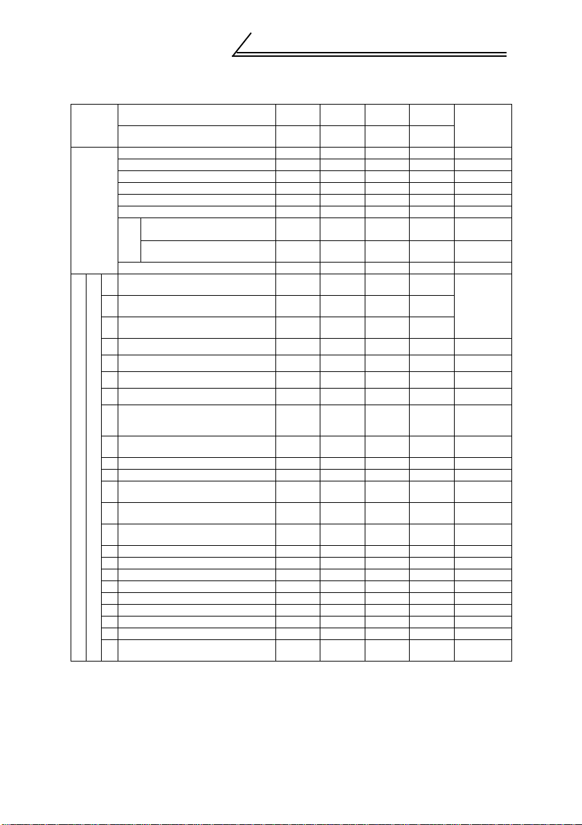
3.1 List of Dedicated Communication Parameters
When this option unit is mounted, extended functions of the following
parameters become available.
Perform setting as required.
FR-A500/F500 series parameter
Parameter
Number
338
339 Speed command source 0, 1 1 0 15
340
500
501
502
*1 Pr. 500 t o Pr. 50 2 are available only with the FR -A500 series.
Refer to the inverter manual for the availability of the par am eters.
Operation control
command source
Link startup mode
selection
Communication error
(*1)
recognition waiting time
Communication error
(*1)
occurrence count display
Communication error-time
(*1)
stop mode selection
Name
Setting
Range
0, 1 1 0 15
0 to 2 1 0 12
0 to
999.8s
0 to 2 1 0 21
Minimum
Setting
Increments
0.1s 0 19
01020
Factory
Setting
FR-V500 series parameter
Parameter
Number
338
339 Speed command source 0, 1 1 0 17
340
400
402
500
501
502
Operation control
command source
Link startup mode
selection
DI11 terminal function
selection
DI12 terminal function
selection
DI13 terminal function
selection
Communication erro r
recognition waiting time
Communication erro r
occurrence count display
Communication error-time
stop mode selection
Name
Setting
Range
0, 1 1 0 17
0 to 2 1 0 12
0 to 3, 5,
8 to 12,
14 to 16, 20,
22 to 27,
42 to 44,
9999
0 to 999.8s 0.1s 0 19
01020
0 to 2 1 0 21
Minimum
Setting
Increments
1 9999 —401
Factory
Setting
Refer
to
page
Refer
to
page
8
INVERTER SETTING
3.2 Operation Mode
The inverter mounted with the option unit (FR-A5NPA) has the following
operation modes:
(1) PU operation [PU] .................Controls the inverter from the keyboard
)) or
of the operation panel (FR-DU04(
-1
parameter unit (FR-PU04(V)) (referred
to as the "PU") installed to the inverter.
(2) External operation [EXT] .......Controls the inverter by switching on/off
external signals connected to the
control circuit terminals of the inverter.
(3) Network operation [NET].......Controls the inverter with instructions
from the Profibus master module via the
option unit (FR-A5NPA).
(The operation signal and running
frequency can be entered from the
control circuit terminals depending on
the Pr. 338 "operation control command
source" and Pr. 339 "speed command
source" setting.)
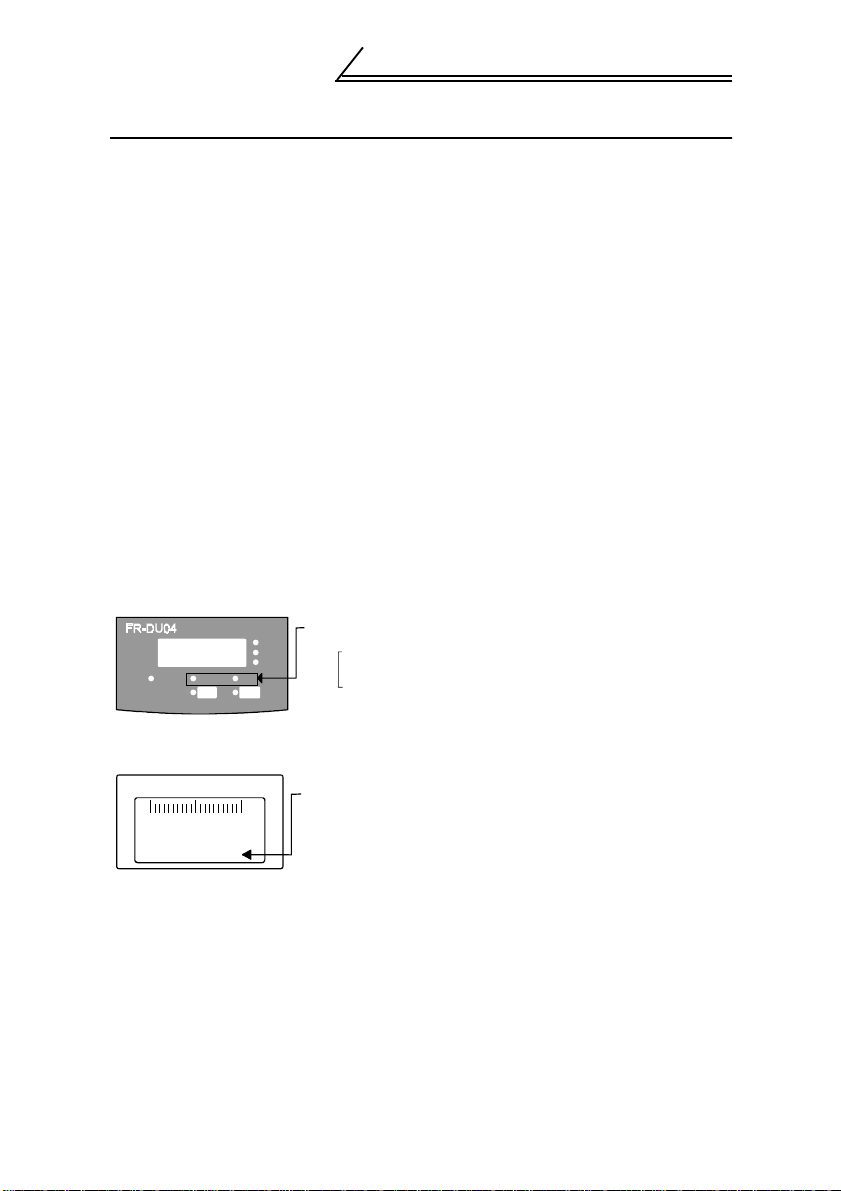
3.2.1 Operation mode indication
FR-DU04
(-1)
MON EXT PU
FR-PU04(V)
STF FWD PU
CONTROL PANEL
Hz
A
V
FWDREV
OL
Hz
Operation mode indication (lit)
PU : PU operation mode
EXT: External operation mode
Network operation mode
Operation mode indication
PU : PU operation mode
EXT: External operation mode
NET: Network operation mode
9

INVERTER SETTING
3.2.2 Operation mode switching
(1) Operation mode switching conditions
Before switching the operation mode, check that:
1) The inverter is at a stop;
2) Both the STF and STR signals are off; and
3) The Pr. 79 "operation mode selection" setting is correct.
(For setting, use the inverter's operation panel or optional
parameter unit.)
Pr. 79
Setting
0 PU or external operation
1 PU operation Disallowed
2 External operation Allowed
3, 4 E xt er na l/PU c om bi ned operation Disal l owed
5
6 Switch-over Allowed
7
8 PU or external (signal switching)
*1 Programmed operation is available o nl y wi th the FR -A 500 series.
Operation Mode Selection
*1
Programmed operation Disallowed
External operation
(PU operation interlock)
Switching to Network Operation
Mode
Disallowed when the PU mode is
selected. Allowed whe n th e external
mode is selected.
Allowed only in the external ope ra tio n
mode when the PU interlock signal
(X12) is on.
Allowed only in the external ope ra tio n
mode (X16 on).
10
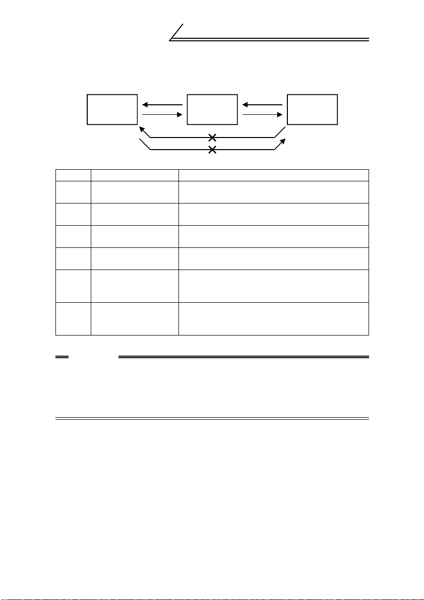
(2) Operation mode switching method
INVERTER SETTING
Switched via Profibus
master module
Network
operation
C
D
External
operation
F
Switched
from PU
A
PU operation
B
E
(Switching disallowed)
Symbol Switching Type Switching Method
PU operation
A
→ External operation
External operation
B
→ PU operatio n
External operation
C
→ Network o p eration
Network operation
D
→ External operation
PU operation
E
→ Network operation
Network operation
F
→ PU operatio n
Operate the external oper at i on key on the PU.
Operate the PU operation key on t he PU.
Switch to the network ope ra t io n m ode via
Profibus master module.
Switch to the external operation mode via
Profibus master module.
Switching disallowed. Allowed if external
operation is selected in A an d net w ork operation
is then selected in C. *1
Switching disallowed. Allowed if external
operation is selected in D and PU operation is
then selected in B. *1
*1 In the switch-over mode (Pr. 79 = 6), switching in E and F is allowed.
CAUTION
1. When "1" or "2" is set in Pr. 340 "link startup mode selection",
the operation mode is network operation at power on or inverter
reset.
2. When setting "1" or "2" in Pr. 340, the initial settings of the
inverter must be made without fail.
11

INVERTER SETTING
(3) Link startup mode selection (Pr. 340)
The operation mode at power on and at restoration from instantaneous
power failure can be selected.
To choose the network operation mode, set "1" or "2" in Pr. 340.
After the link has started, parameter write is enabled by the Profibus
master module.
Pr . 340
Setting
0
(Factory
Setting)
*1 Programmed operation is available only with the FR-A500 serie s.
Operation Mode
Pr. 79
PU or external
0
operation
1 PU operation Inverter operates in the PU operation mode.
External
2
operation
External/PU
3
combined
operation
External/PU
4
combined
operation
Programmed
1
5*
operation
6 Switch-over
PU operation
7
interlock
Operation mode
8
switch-over by the
external signal
Mode at Power On or at Restoration
from Instantaneous Pow er Failu re
Inverter operates in the ext er nal operation
mode.
Inverter operates in the ext er nal operation
mode.
Inverter operates in the external/PU combined
operation mode.
Input running frequency/running speed from
the PU and the start signal from outside .
Inverter operates in the external/PU combined
operation mode.
Input running frequency/running speed from
outside and the start sign al from th e PU.
Inverter operates in the programmed operation
mode.
Inverter operates in the ext er nal operation
mode.
Operation mode is swi t ched while running.
X12 signal ON .....Inverter operates in the
external operation mo de.
(Operation mode can be
switche d to the PU
operation mode from the
parameter unit.)
X12 signal OFF....Inver t er oper at e s in the
external operation mo de.
X16 signal ON .....Inverter operates in the
external operation mo de.
X16 signal OFF....Invert er oper at es in the PU
operation mode.
12

INVERTER SETTING
Pr . 340
Setting
2
1, (2*
)
*1 Programmed operation is available only with the FR-A500 serie s.
*2 When Pr. 340 = "2"
The inverter will resume the same operation state which was in before the
instantaneous powe r failure occurrence when value s ot her than "9999" are set
in Pr. 57 (with restart).
(This setting is mainly used for computer link option (FR-A5NR).)
Operation Mode
Pr. 79
PU or network
0
operation
1 PU operation Inverter operates in the PU operation mode.
Network
2
operation
External/PU
3
combined
operation
External/PU
4
combined
operation
Programmed
1
5*
operation
6 Switch-over
PU operation
7
interlock
Operation mode
8
switch-over by the
external signal
Mode at Power On or at Restoration
from Instantaneous Pow er Failu re
Inverter operates in the network operation mode.
(Profibus master module need not be used for
switching)
Inverter operates in the network operation mode.
(Profibus master module need not be used for
switching.)
Inverter operates in the external/PU combined
operation mode.
Input running frequency/running speed from
the PU and the start signal from outside .
Inverter operates in the external/PU combined
operation mode.
Input running frequency/running speed from
outside and the start sign al from th e PU.
Inverter operates in the programmed operation
mode.
Inverter operates in the network operation
mode.
Operation mode is swi t ched while running.
Refer to the inverter manual for details.
X12 signal ON .....Inverter operates in the
network operation mode.
(Operation mode can be
switched to the external
operation mode by the
Profibus master module.)
X12 signal OFF....Inver t er oper at e s in the
external operation mo de.
X16 signal ON .....Inverter operates in the
network operation mode.
(Operation mode can be
switched to the external
operation mode by the
Profibus master module.)
X16 signal OFF....Invert er oper at es in the PU
operation mode.
13

INVERTER SETTING
REMARKS
1. T he Pr. 340 value may be changed from the PU in any op er at io n m ode.
2. Computer programm ing, w hi ch has stopped due to an instant aneous power
failure or like during net w or k op eration, remains stoppe d even if power is
recovered.
3. When Pr. 340 = "2 ":
When a start command is given from the network with restart enabled (Pr. 57
≠ 9999), a start command during power off (including in st antaneous power
failure and power failure) is stored. Therefore, the inverter resumes operation
in the state before power i ng off at powering on again (power re st or at i on) .
14

INVERTER SETTING
3.3 Operation and Speed Command Source
In the network operation mode, commands from the external terminals and
Profibus master module are as listed below.
(For Pr. 180 and higher (input terminal function selection), assigned s ignals
differ depending on inverters. For details, refer to the inverter manual.)
3.3.1 FR-A500/F500 series
Control
location
selection
Fixed functions
Selective functions
Pr. 338 "operation control
command source"
Pr. 339 "speed command
source"
Forward rotation command (STF) NET NET External External
Reverse rotation command (STR) NET NET External External
Start self-holding s election (STOP) — — External External
Output stop (MRS)
Reset (RES)
Network operation frequency NET — NET —
to terminals)
2 — External — External
4 — External — External
(Functions equivalent
1
Low-speed operation com man d
0
(RL)
Middle-speed operation command
1
(RM)
High-speed operation com man d
2
(RH)
3 Second function selection (RT) NET NET External External
4 Current input selection (AU) —
5 Jog operation select ion (JOG ) — — External Exte rna l
Automatic restart after
6
instantaneous power failure
selection (CS)
7 External thermal relay input (OH) External External External External
8 15-speed selection (R EX ) NET External NET E xte rna l Pr. 59 = 0
9 Third function (X9) NET NET External External
FR-HC connection, FR-CV
10
connection (inverter operation
enable) (X10)
Pr. 180 to Pr. 186 settings
FR-HC connection, instantaneous
11
power failure detection (X11)
12 PU ope r at i on e xt e rn a l i n te r lo c k ( X1 2 ) External External External External
External DC injection braking start
13
(X13)
14 PID control valid terminal (X14) NET External NET External
Brake opening completion signal
15
(BRI)
PU operation-external oper ati o n
16
switching (X16)
0: NET 0: NET
0: NET
Combined Combined
Combined Combined Combined Combined
Compen
External External External External
External External External External
External External External External
External External External External
1: External
External
sation
NET External NET External P r. 59 = 0
NET External NET External P r. 59 = 0
NET External NET External P r. 59 = 0
Combined
NET NET External External
NET NET External External
1: External 1: External
0: NET
External External (*1, 2)
Compen
sation
—
1: Exte rnal
External
Combined
REMARKS
15

INVERTER SETTING
Control
location
selection
Selective functions
RH, RM,
RL, RT
selective
functions
Pr. 338 "operation control
command source"
Pr. 339 "speed command
source"
Load pattern selection-forward/
17
reverse rotation boost switching
(X17)
18 Magnetic flux-V/F switching (X18) NET NET External External
Load torque high-speed frequency
19
(X19)
S-pattern acceleration/
20
deceleration C selection terminal
(X20) *3
22 Orientation command (X22) *3 NET NET External External
Pr. 180 to Pr. 186 settings
23 Pre-excitation (LX) *3 NET NET External External
Remote setting (RH, RM, RL) NET External NET External Pr. 59 = 1, 2
Programmed operation group
selection (RH, RM, RL) *4
Stop-on-contact selection 0 (RL) *4 NET External NET External
Stop-on-contact sel ection 1 (RT) *4 NET NET External External
0: NET 0: NET
0: NET
1: External
NET NET External External
NET NET External External
NET NET External External
————
1: External 1: External
0: NET
1: Exte rnal
REMARKS
Pr. 79 = 5
Network
operation is
disabled
Pr. 270 = 1,
3
External : Contro l b y si gn al from external terminal is only valid.
NET : Control from Profibus mast er module
is only valid.
Combined : Cont rol from both externa l terminal and Profib us master module
is valid.
— : Control from both externa l terminal and Profib us master module
is invalid.
Compensation : Control by signal from external terminal is only valid if Pr. 28
"multi-speed input com pensation" setting is "1".
*1 If the FR -HC conne ction, FR-CV connect ion (inverter operation enable sign al)
(X10) is not assigned when "2" is set in Pr. 30 "regenerative function se le cti on"
(when the FR-HC or FR-CV is used) or if the PU op eration interlock signal
(X12) is not assigned when "7" (when the PU operation interlock function is set)
is set in Pr.79 "operation mode selection" , this function is also us ed by the
MRS terminal and the refore operation is only valid for the exter nal terminal,
independently of Pr. 338 and Pr. 339 settings.
*2 When the MRS signal is assigned to both netwo rk and external control, the
output stop command is as listed below:
Network External
Output Stop Command
Pr. 17 = 0 Pr. 17 = 2
ON ON Output stopped Output not stopped
ON OFF Output stopped Output stopped
OFF ON Output stopped Output stopped
OFF OFF Output not stopped Ou tp ut sto pp ed
*3 This settin g is v al id only when the FR- A5AP option is moun te d. ( T h e FR-A5AP
cannot be used with the FR- F 5 00 series.)
*4 Programmed operation is available o nl y wi th the FR -A 500 series.
16
INVERTER SETTING
3.3.2 FR-V500 series
Control
location
selection
Fixed functions
Selective functions
Pr. 180 to Pr. 183, Pr. 187 se ttings *1
Pr. 338 "operation control
command source"
Pr. 339 "speed command
Forward rotation command (STF) NET NET External External
Reverse rotation command (STR) NET NET External External
Reset (RES)
External thermal relay (OH) External External External External
Computer link operation speed NET — NET —
2 — External — External
to terminals)
1
(Functions equivalent
3 — External — External
Low-speed operation command,
0
Remote setting (setting clear) (RL)
Middle-speed op er ati on comma nd ,
1
Remote setti ng (de cel er at io n) ( RM )
High-speed operation c ommand,
2
Remote setting (acceleration) (RH )
3 Second funct ion selection (RT) NET NET External External
5 Jog operation selection (JOG) — — External External
8 15-speed selection (REX) NET External NET External
9 Third function (X9) NET NET External External
FR-HC connection, FR-CV
10
connection (inverter operation
enable) (X10)
FR-HC connection (instantaneous
11
power failure detection) (X11)
12 PU operation external interlock (X12) External External External External
14 PID control enable terminal (X14) NET External NET External
Brake sequence opening
15
completion signal (BRI)
PU-external operation sw itcho ver
16
(X16)
S-pattern acceleration/deceleration
20
C switchover (X20)
22 Orientation command(X22) NET NET External External
23 Pre-excitation/servo ON (LX) NET NET External External
24 Output stop (MRS)
25 Start self-holding selection (STOP) — — External External
26 Control mode changing (MC) NET NET External External
27 Torque restriction selection (TL) NET NET External External
42 Torque bias selection 1 (X42) NET NET External External
43 Torque bias selection 2 (X43) NET NET External External
P control selection (P/PI control
44
switchover) (X44 )
source"
Speed setting auxiliary
Magnetic flux command/
regeneration torque restriction
External : Control by signal from external terminal is only valid.
NET : Control from Profibus master module
Combined : Control from both e xter nal ter minal an d Prof ibus maste r mo dule is
valid.
— : Control from both ext ernal ter minal and Pr ofibus mas ter mo dule is
invalid.
Compensation : Control by signal from external terminal is only valid if Pr. 28 "multi-
speed input compensat i on" setting is 1.
0: NET 0: NET
0: NET
1: Exte rnal
Combined Combined Combined Combined
Compen
External External External External
External External External External
External External External External
External External External External
Combined Combined
External
sation
NET External NET External
NET External NET External
NET External NET External
NET NET External External
NET NET External External
NET NET External External
1: External 1: External
0: NET
1: External
Compen
External External *2
is only valid.
sation
External
REMARKS
Pr. 59 ≠ 0:
Remote
setting
17
 Loading...