

Mitsubishi FR-A5ND Instruction Manual

FR-A5ND
DeviceNetTM Communications
Option Unit
used with
A500(L) Series
Variable Frequency Drive
Instruction Manual
MITSUBISHI ELECTRIC
AUTOMATION

ii
MITSUBISHI ELECTRIC AUTOMATION
DeviceNet is a registered trademark of Open DeviceNet Vendor Association (ODVA).
DeviceNetManager is a trademark of Allen-Bradley Company Inc.
Windows, DOS and other product names may be trademarks or registered trademarks of
their respective companies.

FR-A5ND
DeviceNetCommunications Option Unit
iii
NOTES, CAUTIONS AND WARNINGS
NOTE: Notes are used to provide additional detail about a procedure. The
Note will always precede the text that the Note refers to.
CAUTION: Cautions provide additional detail where failure to observe the
Caution may result in damage to the equipment or slight injury
to the user.
WARNING: Warning provide additional information, where failure to observe
the Warning may result in death or severe injury
SAFETY INSTRUCTION
1. Electric Shock Prevention
WARNING: Do not open or remove the front cover while the Variable
Frequency Drive is running. You may get an electrical shock.
When necessary to perform inspections or when wiring the
unit, switch power off and wait at least 10 minutes and until
the bus charge light is off. Check for residual voltage.
Do not attempt to inspect or wire this unit unless fully com-
petent to perform the work.
Be sure hands are dry before operating any switches.
Be sure cables do not have scratches, excessive stress,
heavy loads or pinching to prevent electrical shock
2. Injury Prevention
CAUTION: Be sure all connections are in accordance with instructions
in this manual
Check that cables are properly connected before turning
equipment on.
After turning equipment off, wait at least 10 minutes and
until the bus charge light is off before removing cover. With
cover removed, charged components may be exposed.

iv
MITSUBISHI ELECTRIC AUTOMATION
3. Additional Cautions and Warnings
CAUTION: Do not install the option unit if it is damaged or has parts
missing
Check that option unit is securely fastened to the variable
frequency drive.
Do not stand or rest heavy objects on top of unit.
Do not allow metal fragments, conductive bodies, oil or other
flammable substance to enter the variable frequency drive.
Before starting operation, confirm and adjust the parameters.
Failure to do so may cause the machines to make unexpected motions.
When parameter clear or all parameter clear is performed,
each parameter returns to the factory setting. Reset the
required parameters before starting operation
For prevention of damage caused by static buildup, touch a
nearby metal object to remove static from your body.
Dispose of this product as general industrial waste.
WARNING: Do not modify this equipment

FR-A5ND
DeviceNetCommunications Option Unit
v
TABLE OF CONTENTS
Page
1. INTRODUCTION .............................................................................. 1
General ............................................................................................. 1
Description ....................................................................................... 1
2. INSTALLATION ................................................................................ 3
2.1. Pre-Installation Checks .............................................................. 3
2.2. Installation Procedures .............................................................. 4
2.3 Pre Network Connection Procedure ............................................ 8
2.4 Connection to Network ................................................................ 9
2.5 Changing Node Addresses ....................................................... 10
2.6 LED Status Indicator................................................................. 11
3. GETTING STARTED .......................................................................... 12
3.1. Introduction .............................................................................. 12
3.2. Basic Configuration .................................................................. 13
3.3. Loss of Communications ......................................................... 14
4. OPERATION ...................................................................................... 14
4.1. Operation Modes ..................................................................... 14
4.2. Operation Mode Selection ...................................................... 15
4.3. Functions Available in Operation Modes .................................. 16
4.4. Input from DeviceNet to VFD .................................................... 16
4.5. Output from VFD to DeviceNet ................................................. 17
4.6. Operation on Alarm Occurrence ............................................... 19
4.7. VFD Reset............................................................................... 19
4.8. Setting Frequency (f) Value...................................................... 19
4.9. Parameter Clear (Pr Clr) Commands ........................................ 19
4.10. Control Input Commands .......................................................... 20
5. FR-A5ND SPECIFIC PARAMETERS .................................................. 20
5.1. Prs.345 & 346 ......................................................................... 20
5.2. Other Option-Specific Parameters ........................................... 24
6. OBJECT MAP .................................................................................... 25
6.1. Class 0x01 - Identity Object..................................................... 25
6.2. Class 0x03 - DeviceNet Object ................................................ 26
6.3. Class 0x04 - Assembly Object ................................................ 27
6.4. Class 0x05 - DeviceNet Connection Object .............................. 31

vi
MITSUBISHI ELECTRIC AUTOMATION
6.5. Class 0x28 - Motor Data Object ............................................... 37
6.6. Class 0x29 - Control Supervisor Object .................................... 38
6.7. Class 0x2A - AC Drive Object .................................................. 39
6.8. Class 0x66 - A500(L) Extended Object I .................................. 43
6.9. Class 0x67 - A500(L) Extended Object II ................................. 49
6.10. Response Timing ................................................................... 55
6.11. Recommendation For Software Developers ............................ 55
7. A500(L) PARAMETERS ..................................................................... 56
8. TROUBLESHOOTING ....................................................................... 65
8.1. Inspecting Display On Parameter Unit And MNS
Status LED On A5ND ............................................................. 65
9. REFERENCES ................................................................................... 66
10. SPECIFICATIONS ........................................................................... 67
APPENDIX A ......................................................................................... 68
REVISIONS ........................................................................................... 69

FR-A5ND
DeviceNet Communications Option Unit
1
1. INTRODUCTION
GENERAL
The purpose of this manual is to provide general information, installation, and
operation procedures for the FR-A5ND DeviceNet option, used with the
FR-A500(L) Variable Frequency Drive, herein after referred to as the VFD.
Read this manual completely before installing, operating or servicing the
option unit.
This manual is intended for use by qualified personnel. Installation should
only be performed by qualified personnel. You must be able to operate and
program serial devices to use the equipment.
This option allows the VFD to be connected to a network adhering to the
DeviceNet communications protocol.
Illustrations provided in this manual may have covers or safety guards removed to provide a clear view. Before starting operation of the product be sure
to install covers and guards into the original position.
The following is a list of important features for the option unit
Data Rates of 125K baud, 250K baud, and 500K baud.
Up to 64 stations supported on a single network
Ability to add or remove stations without disrupting network operation.
Network access to all VFD parameters, Start/Stop commands, and moni-
tor data.
Passed ODVA Conformance Test in January, 1998
Designed and assembled in the U.S.A..
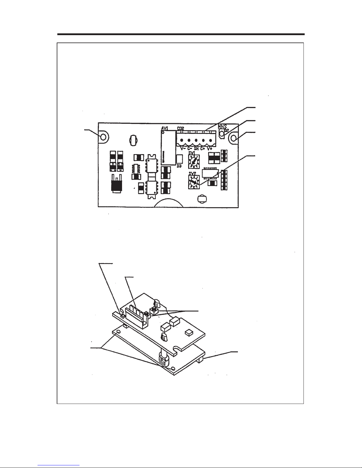
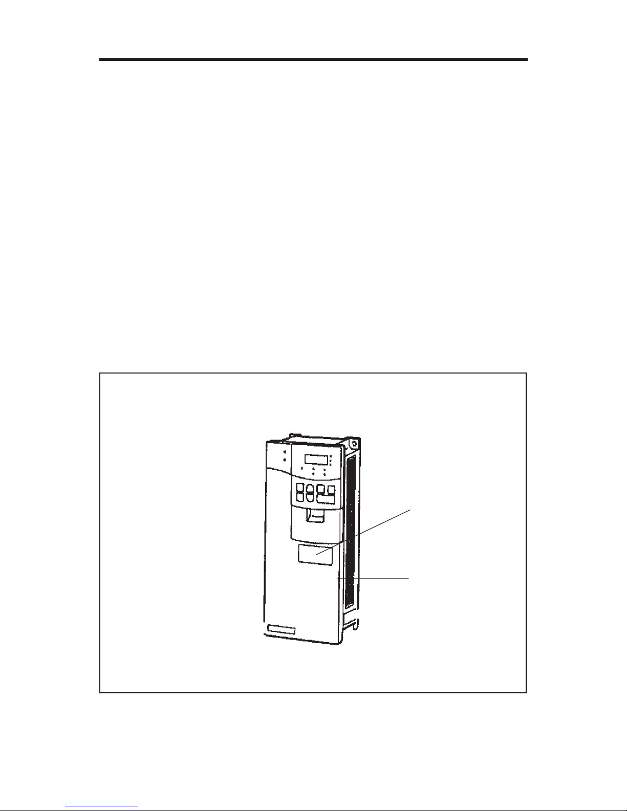
DESCRIPTION
The FR-A5ND option unit consists of two circuit boards as shown in Figure
1-1. The option unit is mounted in option port #3 on the VFD unit. Two station
switches, mounted on the top printed circuit board, allow the assigning of
station numbers from 0 to 63. An LED status light mounted next to the
DeviceNet connector provides status information on the communication link.
2
MITSUBISHI ELECTRIC AUTOMATION
Figure 1-1. FR-A5ND Option Unit
TOP VIEW
Mounting
Hole
DeviceNet
Connector
Status LED
Mounting
Hole
Station
Number
Switches
Status LED
DeviceNet Connector
Station Number Switches
Connector to
Inverter
Mounting
Holes

FR-A5ND
DeviceNet Communications Option Unit
3
2. INSTALLATION
Installation requires the removal of the VFD cover. The VFD top cover must
be removed to install the option unit. After installation, the top cover is reinstalled and connection to the DeviceNet bus is completed through a connector accessible through the top cover.
WARNING: Cover removal can expose charged components. Be sure the
proper procedures are followed when removing cover.
Remove cover following the procedure in the VFD manual.
2.1. Pre-Installation checks
dedulcnigniwollofehttahtyfireV
.deilppuserastnenopmoc
tinUnoitpODN5A-RF.1
8x3MswercsgnitnuomowT.2
)502M698PSV(
launaMnoitcurtsnI.3
.epytDFVehtyfireVotdengisedsitinunoitposihT
seireS)L(005Aehthtiwkrow
.)DFV(evirDycneuqerFelbairaV
htiwtinusihtesuottpmettatonoD
,002A,001A.g.e(DFVrehtoyna
sledomesehT.)seireSEdna,F,Z
rotcennocnoitpotnereffidaesu
ehtsecrofresuehtfidna
ebyamDFVeht,rotcennoc
.degamad
rewoptupniDFVehttahterusnE
.ffodenrutsi
tinunoitpoehtro/dnaDFVehT
htiwdellatsnifidegamadebyam
nasmrofrepDFVehT.norewop
norewoptaerudecorpnoitazilaitini
noitpoehtgnikcehcsedulcnitaht
retalnoitpoehtgniddA.trop
hcihwtcilfnocerawdrahasesuac
."3PO.E"mralaehtnitluserlliw
roDFVehtegamadyamdnA
.tinunoitpo
4
MITSUBISHI ELECTRIC AUTOMATION
2.2. Installation Procedure
Mounting Option Unit In VFD Option Port #3.
1. Verify that power has been turned off and that the VFD top cover has
been removed.
NOTE: The FR-A5ND option unit must be installed in Option Port #3 only.
An attempt to install in any other port may cause the VFD or the
option unit to be damaged.
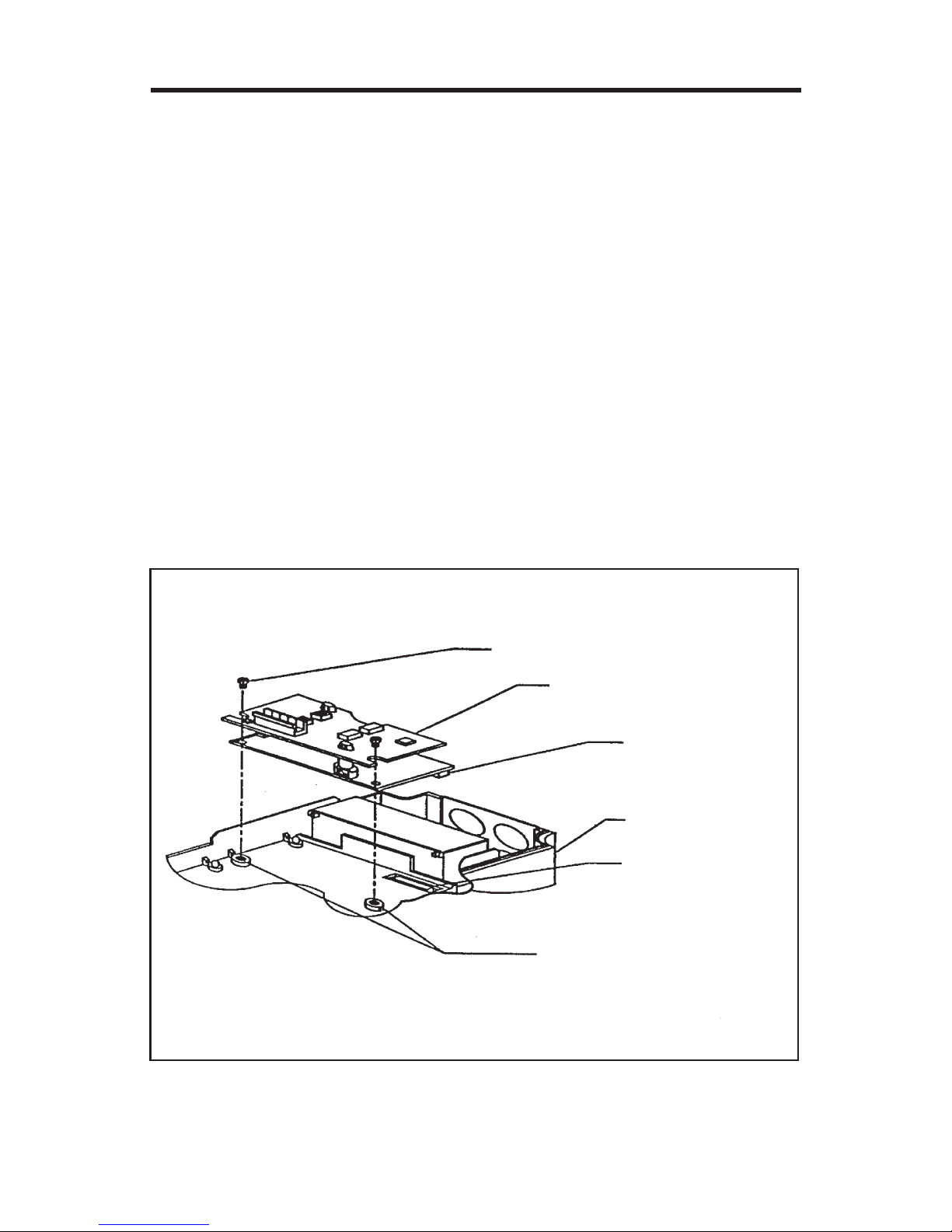
2. Using the two mounting holes for alignment reference, carefully insert
the option unit connector into the VFD connector as shown in Figure 21 and firmly press the unit into place.
NOTE: If screw holes in option unit do not line up with the VFD mounting
holes, check that connector has been correctly fitted.
3. Secure the option unit to the VFD with the two mounting screws.
4. Option unit is now mechanically installed as shown in Figure 2-2.
Figure 2-1. Option Unit aligned with Option Port #3
VSP896M205
3 x 8 mm Machine Screws
with Flat and Lock Washer
FR-A5ND Plug-in Option
Option to VFD
Connector
Mitsubishi
Inverter
VFD Option
Port 3
Machine Screw Inserts
FR-A5ND
DeviceNet Communications Option Unit
5
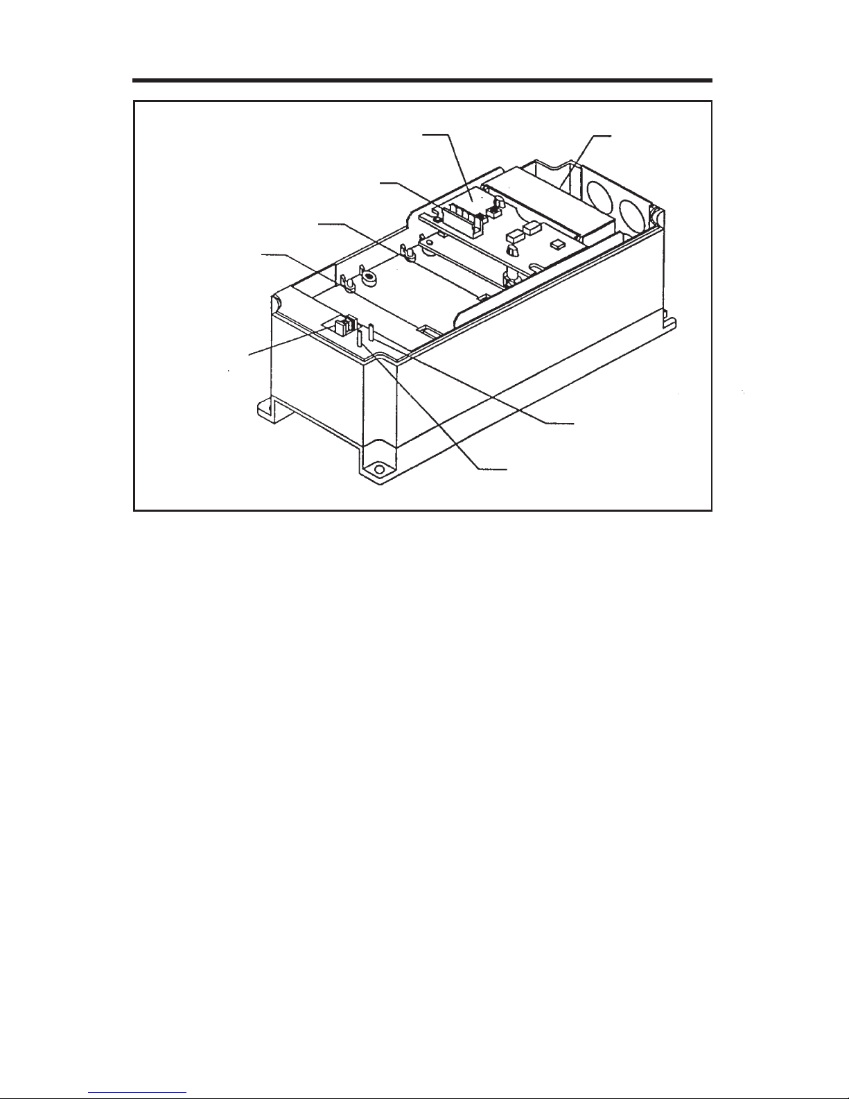
Figure 2-2. FR-A5ND Option Unit Installed in VFD
Constructing DeviceNet Drop Cable
A DeviceNet drop cable, Figure 2-3, is used to connect the FR-A5ND option
unit to the DeviceNet network. The drop cable consists of an ODVA approved
thin cable as well as an ODVA approved 5-pin connector that mates with
the FR-A5ND DeviceNet Option connector. Another connector compatible
with the networks trunk cable must also be selected by the user/installer.
Recommended parts are:
DeviceNet Thin Cable: Belden part number 3084A or equivalent.
5-Pin Connector for FR-A5ND: Phoenix Contact part number MSTBP 2.5/5ST-5.08 AB AU SO.
Terminal
Block
B
o
tto
m
Top
Alarm Lamp
Power Lamp
Parameter
Unit Port
VFD Option
Port 1
VFD Option Port 2
Connector to DeviceNet
Installed DeviceNet Option in Port 3
6
MITSUBISHI ELECTRIC AUTOMATION
NOTE: Maximum length of drop cable must not exceed 20 feet.
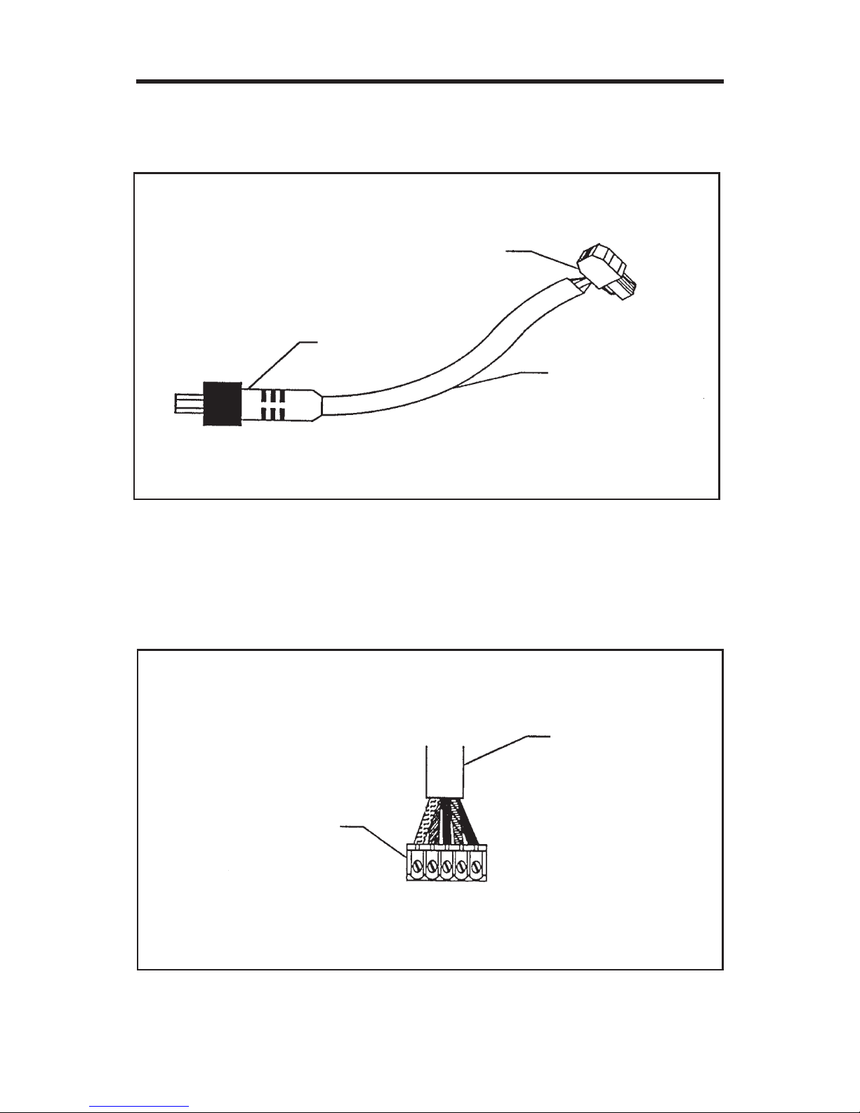
Figure 2-3. DeviceNet Cable
The DeviceNet option connector pin out connections are shown in Figure 2-4.
The function for each pin is listed in Table 2-1.
Figure 2-4. Connector Pin Out Diagram
DeviceNet Option Connector for FR-A5ND
To Netw ork
Trunk Cable
DeviceNet Thin
Drop Cable
DeviceNet Thin
Drop Cable
DeviceNet Option Connector
for FR-A5ND
V- V+C+C- S H

FR-A5ND
DeviceNet Communications Option Unit
7
Table 2-1. Pin Out Functions
1. Strip the insulation and shielding back 1.5 inches on the free wire end of
the drop cable to expose the four colored signal wires and the silver
shield wire.
2. Strip the insulation back about ¼ inch on the signal wires. And tin each
lead with solder.
3. Tin the end of the shield wire to prevent fraying.
4. Attach the connector to the DeviceNet cable as follow:
a. Using a flathead screwdriver (3.75 mm maximum width), insert the
screwdriver into the upper holes of the connector plug, Figure 2-4, to
open the clamps in the lower holes to allow wires to be inserted.
b. Install the signal wires into the Phoenix Contact connector plug as
shown in Figure 2-4. Be sure to match the wire colors to the correct
pin as shown in Table 2-1.
c. After all wires are properly inserted, turn the holding screws, Figure
2-4 clockwise to securely clamp the wires. When properly tightened,
wires should not be able to be pulled out
.oNniProloClangiS
1kcalB-V
2eulB-NAC
3eraBdleihS
4etihW+NAC
5deR+V
8
MITSUBISHI ELECTRIC AUTOMATION
2.3 Pre Network Connection Procedure
NOTE: Each Device on the network must be assigned a unique station
number between the values of 0 to 63
1. Set the two Station number switches , Figure 1-1, for a address between
0 and 63. Any number out of the range of 0 to 63 is automatically changed
to 63 by the option unit software.
2. Be sure that the FR-A5ND option unit is snugly inserted into the VFD
and the option unit connector is fully and firmly seated before proceeding.
3. Remove the option data port insert, Figure 2-5 from the VFD cover.
4. Reinstall the VFD cover making sure that option port opening is aligned
with the DeviceNet connector.
5. Connect the DeviceNet thin drop cable to the VFD by inserting the 5-pin
connector through the data port opening, into the DeviceNet standard
socket on the option unit.
Figure 2-5. VFD Data Port
Option Data Port
Inverter Cover

FR-A5ND
DeviceNet Communications Option Unit
9
2.4 Connection to Network
At this point the option unit should be installed in the VFD, the address
switches properly set, the cable constructed, and the connector connected
to the option unit through the option data port.
CAUTION: Do not connect cable to the network until told to do so.
1. Check that power is turned off to the VFD.
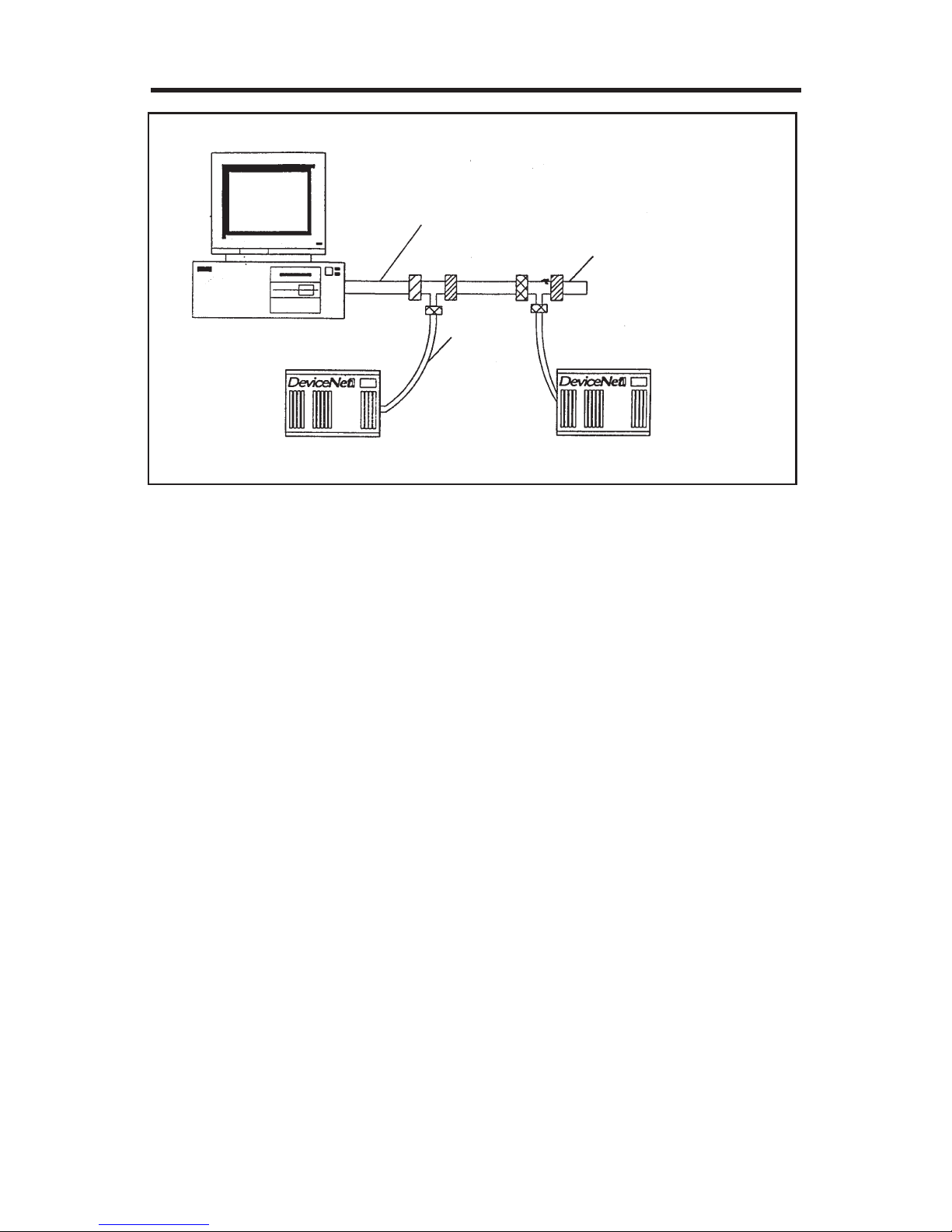
2. Make sure that the terminating resistor is installed at each end of the
trunk cable, as shown in Figure 2-6. These resistors must meet the
following requirements:
a) R = 121 ohms
b) 1% metal film
c) 0.25 Watts
3. Connect cable to network as follows:
a) If the trunk connector is a DeviceNet sanctioned pluggable or sealed
connector, the connection to the active network can be made at any
time whether VFD is on or off. The option unit automatically detects
when the connection is completed.
b) If connecting to the network with free wires, power to the network and
VFD should be shut off as a safety precaution in case two or more
signal wires are accidentally shorted together.
4. Check that all connections are completed, and all necessary wires not
associated with DeviceNet are connected to the VFD unit
5. It is now safe to apply power to the VFD and run it in the PU or external
mode.
10
MITSUBISHI ELECTRIC AUTOMATION
Figure 2-6. Connection to System
2.5. Changing Node Addresses
NOTE: The state of the address switches is sampled once at power on.
Changing the address later on will have no effect and the software
will keep the number read at power on.
To change the address switches proceed as follows.
1. Turn power off.
2. Disconnect drop cable from option unit.
3. Remove VFD cover.
4. Set address switches for desired address.
5. Reinstall VFD cover.
6. Reconnect drop cable to VFD option unit.
7. Turn power on.
Trunk Cable Stub Containing
Terminating Resistor
(121+Ohms)
Drop
Cable
IBM Compatible

FR-A5ND
DeviceNet Communications Option Unit
11
2.6. LED Status Indicator
The LED Status indicator labeled MNS (see Figure 1-1) provides information
on the status of operation as shown in Table 2-2. The indicator has five states,
Off, Blinking Green, Steady Green, Blinking Red, and Steady Red.
After connecting the drop cable to the trunk of the active network, observe
the condition of the Status LED. The option unit uses the Combined Module/
Network status LED scheme described in the DeviceNet communications
standard.
Table 2-2. LED Status
* Time Limit = 4 x EPR (Expected Packet Rate)
NOITIDNOCDELMETSYSFOETATSETON
ffOfforewopretrevnI
retrevnIdnakrowteN
norewop
.norewopretrevnInruT
nehtlliwtinunoitpO
noitatsetacilpudetelpmoc
.tsetrebmun
neerGgniknilBteytonnoitcennoC
tsohybdehsilbatse
sahtinunoitpOehT
yllufsseccuspuderewop
stitahtdenimreteddna
tonseodrebmunnoitats
.snoitatsrehtohtiwtcilfnoc
teytonsahtsoha,revewoH
adehsilbatse
.knilsnoitacinummoc
neerGydaetSretrevnIdnakrowteN
norewop
dehsilbatsenoitcennoC
tsohyb
ehtnoecivedretsamA
ehtdetangisedsahkrowten
roftinunoitpo
DEL.snoitacinummoc
gnirudoslaetatssihtsdloh
.noitacinummoc
deRgniknilBtuo-emitnoitcennoCnoitpOdetangisedretsaM
noitacinummocroftinu
nehttub,)etatsneergDEL(
nihtiwsegassemontnes
ehtnitestimilemiteht
*.etartekcapdetcepxe
tsohtahteesotkcehC
neebtonsahnoitats
ehtmorfdetcennocsid
.krowten
deRydaetSeruliafknillacitirCnoitacinummocdeliaF
ecived
rebmunnoitatsetacilpuD-
fforewopkrowteN-
ottinunoitpOmorfelbaC-
rodetcennoctonkrowten
.dereves
degamadkrowteN-
otrewopelcyctsuM
.tluafsihtmorfrevocer

12
MITSUBISHI ELECTRIC AUTOMATION
3. GETTING STARTED
3.1 Introduction
This section is intended to facilitate the configuration of the FR-A5ND DeviceNet
Option with minimum effort. It is assumed that the default values specified in
this section are acceptable to the user. If the user wishes to change these
values, the data necessary to do so is provided later in the manual.
This section assumes that network cabling is complete and DeviceNet communication has been established. The status LED on the FR-A5ND option
should be either blinking green or steady green as described in Table 2-2.
3.1.1 General Description:
The FR-A5ND DeviceNet Option Unit is considered a slave device in the
DeviceNet communication standard. This means that the FR-A5ND cannot
initiate messages on the network. A master device must establish a connection to the Option Unit and then send commands, requests for information,etc.
The FR-A5ND Option Unit supports Group 3 Messaging as defined in the
DeviceNet standard. This feature of the FR-A5ND Option Unit means that it
is possible for one master to control the VFD while another reads data from
the same VFD. This also means that the DeviceNet master must support the
UCMM protocol for proper operation.
3.1.1.1. It is strongly recommended that the user configures the DeviceNet
network using a software tool designed specifically for that purpose. The use
of such a tool greatly simplifies the configuration, reduces confusion, and
enhances accuracy. Additionally, the configuration tool will facilitate the elimination of conflicts between network devices and ensure consistency throughout the network.
One such tool is DeviceNetManager as supplied by Rockwell Automation.
Tools are available from many other suppliers but the descriptions contained
in the Getting Started section are based upon the use of DeviceNetManager.
3.1.1.2. When adding the FR-A5ND DeviceNet Option Unit to an A500(L)
Series VFD that has previously been configured for a specific application, it
may be necessary to complete a Parameter All Clear (PrClr) instruction in the VFD in order to remove unintentional conflicts and to allow the
VFD to recognize the presence of the option card.
If this becomes necessary, you will need to record the existing configuration
before issuing the PrClr command as this command will restore factory default values to all VFD parameters. Once the command is completed and the

FR-A5ND
DeviceNet Communications Option Unit
13
VFD has recognized the FR-A5ND Option Unit, the VFD configuration data
may be re-entered either via the parameter unit or the network.
3.1.1.3. To use the DeviceNetManager software, you will need to acquire
the DeviceNet Electronic Data Sheet (EDS) file. The EDS file is a standard
DeviceNet file which defines the configurable parameters of a field device and
facilitates the network configuration softwares ability to recognize a specific
field device. Please refer to the configuration software tool instruction manual
for more information about the installation and use of EDS files.
The most recent revision of the A500(L) EDS file is available on the Internet
as well as a separate item from Mitsubishi Electric Automation, Inc. See
Appendix A for details on acquiring this file.
3.2. Basic Configuration
3.2.1 Set Baud Rate:
The baud rate must be consistent throughout the network in order to establish communication and allow configuration via the network. Therefore, this
step is critical to the success of the FR-A5ND Option Units configuration.
3.2.1.1. Upon power-up, the FR-A5ND DeviceNet Option Unit will default to a
communication speed of 125 Kbps.
3.2.1.2. The baud rate may be set via the network using Baud Rate, attribute 2 of DeviceNet Class 0x03, instance 1. See section 6.2.3 for further
information.
3.2.1.3. The baud rate may be set manually via the parameter unit by changing Pr345. See section 5.1 for further information.
3.2.1.4. Set Node Address: The station number assigned to the FR-A5ND
Option Unit in section 2.3 will determine the default node address upon VFD
power-up. If, upon network configuration, an address conflict is found, the
Node Address may be set via the using Node Address, attribute1 of the
DeviceNet Class 0x03, instance 1. See section 6.2.3 for further information.
3.2.2. DeviceNet I/O Assembly:
Communication between a master device and a slave device on the network
requires that the DeviceNet Class 0x04 Assembly Object in both devices
be the same.

14
MITSUBISHI ELECTRIC AUTOMATION
3.2.2.1. Default I/O Assembly: Upon power-up, the FR-A5ND Option Unit
will default to Class 0x04 Output Instance 21 and Class 0x04 Input
Instance 71. See Section 6.3 for further information on DeviceNet Class 0x04
and changing the desired Output and Input Instances.
3.2.2.2. Polling Rate: Determination of the proper polling rate of the DeviceNet
master device is dependent upon the characteristics of the entire network. To
minimize potential conflicts and maximize system reliability, a minimum polling
rate interval of 30ms is suggested. The user may, at their discretion, adjust
this rate as network performance allows.
3.3. Loss of Communications
In the default polled communication mode, the FR-A5ND DeviceNet Option
Unit will respond to loss of polling based upon configuration of the Watchdog
Timer Action (WDA) bits of parameter 345 (Pr345) as defined in Section 5.1
of this manual. The default value of these bits is decimal 0. Such loss of
polling may occur upon physical disconnection of network cabling, network
power loss, failure within the master, etc.
When the WDA bits of Pr345 are set to decimal 0, the VFD will continue to
execute the last command received until the communication time-out is
reached. This time out value is equal to 4 times the Expected Packet Rate
(EPR) as configured by the user. Once the FR-A5ND times out, the VFD will
generate an E.OP3 error and decelerate to a stop.
When the WDA bits of Pr345 are set to decimal 2, the VFD will continue to
execute the last command received until another command is issued. The
FR-A5ND will ignore the the communication loss, generate no error and automatically reset the connection when communication is restored.
4. OPERATION
Operation of the A500(L) changes slightly when the FR-A5ND is installed.
These changes are described in the following paragraphs. Parameter definitions including newly created parameters, as well as operation with the FRA5ND installed are described.
4.1 Operation Modes
4.1.1 PU operation mode
Control of the VFD is from the parameter unit (PU).

FR-A5ND
DeviceNet Communications Option Unit
15
4.1.2 External operation mode
Control of the VFD is by external signals connected to the VFDs terminal
block.
4.1.3 Network (computer link) operation mode
Control of the VFD is via commands from a DeviceNet master. However, FRA5ND-specific parameters 338 and 339 can be used to select external control for forward/reverse/stop and output frequency setting.
4.2 Operation Mode Selection
The following chart describes the required actions to change the operation
mode.
For all other mode changes, please consult FR-A500(L) Instruction Manual.
The following conditions must also be met before a mode change can be
effected:
· VFD is stopped
· Forward and reverse commands are off
Parameter 340 allows selection of network operation mode on power up and
after a drive reset.
Mode change Required action
External operation → PU
operation
Press PU key on parameter
unit
PU operation → external
operation
Press EXT key on parameter
unit
External operation → network
operation
DeviceNet connection is
allocated
Network operation → external
operation
All DeviceNet connections are
released

16
MITSUBISHI ELECTRIC AUTOMATION
4.3 Functions Available in Operation Modes
The functions of the drive depend on the mode of the drive. The following chart
indicates the available commands according to the VFD operation mode.
*1: depends on value of Prs.338 & 339
*2: VFD cant be reset if computer link comm. error has occurred
*3: as set in Pr.77
4.4 Input from DeviceNet to VFD
4.4.1 Control Input Commands
FR-A5ND supports STF and STR. Some other Control Input Commands are
supported as well.
4.4.2 Output Frequency Setting
Output frequency setting is possible for the range 0 to 400 Hz in increments
of 0.01 Hz.
edomnoitarepO
epytlortnoCepytdnammoCedomteNlanretxE
edom
UP
edom
teNeciveDdnammocnoitarepO1*seyonon
gnittesqerftupuO1*seyonon
rotinoMseyseysey
etirwretemaraP3*sey
)deppotselihw(
3*on3*on
daerretemaraPseyseysey
daerretrevnI2*seyonon
lanretxE
slanimret
dnammocnoitarepO1*seyseyon
gnittesqerftuptuO1*seyseyon
teserretrevnIseyseysey

FR-A5ND
DeviceNet Communications Option Unit
17
4.4.3 VFD Reset
VFD can be reset via DeviceNet using Identity Object reset service. Note that
this reset service also performs a parameter clear, the type of which depends
on the type of the Identity Object reset service. See Sections 6.1.4, 6.6.3 &
6.7.3 for relevant implementations.
4.4.4 Parameter Writing
For parameter writing, all standard parameters are supported. In addition, the
parameters listed in the Option-specific Parameter section of this specification are supported.
4.5 Output from VFD to DeviceNet
4.5.1 VFD Status
VFD status can be monitored using class 0x2A, attribute 114, the A500(L)
INV Status. This is a bitmapped status byte defined as follows:
4.5.2 VFD Monitoring
The following items can be monitored:
· output frequency
· output current
· output voltage
· frequency setting
Bit Definition
0 Running (RUN)
1 Forward running (FWD)
2 Reverse running (REV)
3 Up to frequency (SU)
4 Overload (OL)
5 Instantaneous power failure (IPF)
6 Frequency detection (FU)
7Alarm (ABC)

18
MITSUBISHI ELECTRIC AUTOMATION
· running speed (RPM)
· motor torque
· converter output voltage
· regenerative brake duty
· electronic overcurrent protection load factor
· output current peak value
· input power
· output power
· input terminal
· output terminal
NOTE: Input/Output terminal assignment functions depend on programmed
Functions such as brake sequence. Please refer to Section 6.7.3
for more details.
Bit-map for Input Terminal Monitor:
Bit-map for Output Terminal Monitor:
The bit-wise data here reflect Prs190~195, if the assignments for terminals
are changed, the bit-map may not be the same.
In the above Bit-maps, 1 means the data is present, 0 means the data is
absent.
4.5.3 Parameter Read
For parameter reading, all standard parameters are supported. In addition,
the parameters listed in the Option-specific Parameter section of this specification are supported.
15..65 43210
0 Relay FU OL IPF SU RUN
21..511101 9 8 7 65432 1 0
0SCSERPOTSSRMGOJHRMRLRTRUARTSFTS
 Loading...