

Mitsubishi Electric FR-A560L-375K, FR-A560L-450K, FR-A560L-900K, FR-A560L-530K Instruction Manual
- INSTRUCTION MANUAL -
FR-A560L-375K~900K-NA
HIGH PERFORMANCE
HIGH-FUNCTIONS
LARGE CAPACITY INVERTER
FR-A500L
MITSUBISHI
ELECTRIC
Supplementary Manual
Refer to Operation/Instruction
Manual for FR-A500L.
A‑1
Thank you for choosing this Mitsubishi Large Capacity Inverter.
This instruction manual gives handling information and precautions for use of this
equipment.
Incorrect handling might cause an unexpected fault. Before using the inverter, please read
this manual carefully to use the equipment to its optimum.
This manual describes the parts which are different from the FR-A500L chassis drive, up to
280kw. Please refer to the FR-A500L instruction manual for further details.
This section is specifically about safety matters
Do not attempt to install, operate, maintain or inspect the inverter until you have read through this instruction
manual and appended documents carefully and can use the equipment correctly.
Do not use the inverter until you have a full knowledge of the equipment, safety information and instructions.
In this instruction manual, the safety instruction levels are classified into “WARNING” and “CAUTION”.
Assumes that incorrect handling may cause hazardous conditions, resulting in
death or severe injury.
Assumes that incorrect handling may cause hazardous conditions, resulting in
medium or slight injury, or may cause physical damage only.
Note that the CAUTION level may lead to a serious consequence according to conditions. Please follow the
instructions of both levels because they are important to personnel safety.
WARNING
CAUTION
A‑2
SAFETY INSTRUCTIONS
1. Electric Shock Prevention
WARNING
z
While power is on or when the inverter is running, do not open the front door. You may get an electric
shock.
z
Do not run the inverter with the front door opened. Contact with the exposed high-voltage term inals or
charging part of circuitry will cause an electric shock.
z
If power is off, do not open the front door except for wiring or periodic inspection. You may access the
charged inverter circuits and get an electric shock.
z
Before starting wiring or inspection, switch power off, wait for more at least 10 minutes and check for the
presence of any residual voltage with meter (see chapter 2 for-further details.) etc.
z
Any person who is involved in the wiring or inspection of this equipment should be fully competent to do
the work.
z
Always install the inverter before wiring. Otherwise, you may get an electric shock or be injured.
z
Operate the switches with dry hands to prevent an electric shock.
z
Do not subject the cables to scr atches, exc essive stres s, heavy loads or pinching. Otherwise, you m ay
get an electric shock.
2. Fire Prevention
CAUTION
z
Install the inverter on an incombustible cubic le. Installing the inverter directly on or near a combus tible
surface could lead to a fire.
z
If the inverter has becom e f aulty, switch off the inverter power. A continuous f low of large c urrent could
cause a fire.
z
Do not connect the resistor directly to the DC terminals +(P), -(N). This could cause a fire.
3. Injury Prevention
CAUTION
z
Apply only the voltage specified in the instruction manual to each terminal to prevent damage, etc.
z
Ensure that the cables are connected to the correct terminals. Otherwise, damage, etc. may occur.
z
Always make sure that polarity is correct to prevent damage, etc.
z
After the inverter has been operating for a relatively long period of time, do not touch the inverter as it
may be hot and you may get burnt.
A‑3
4. Additional instructions
Also note the following points to prevent an accidental failure, injury, electric shock, etc.:
(1) Transportation and installation
CAUTION
z
When carrying products, use correct lifting gear to prevent injury.
z
Ensure that installation position and material can withstand the weight of the inverter. Install according
to the information in the Instruction Manual.
z
Do not operate if the inverter is damaged or has parts missing.
z
Do not stand or rest heavy objects on the inverter.
z
Check the inverter mounting orientation is correct.
z
Prevent screws, wire fragments, conduc tive bodies, oil or other flamm able substances fr om entering
the inverter.
z
Do not drop the inverter, or subject it to impact.
z
Use the inverter under the following environmental conditions:
Ambient
temperature
-10°C to +40°C (14°F to 104°F) (non-freezing) for 530K-900K
-10°C to +40°C (14°F to 104°F) (non-freezing) at VT rating for 375K, 450K
-10°C to +50°C (14°F to 122°F) (non-freezing) at CT rating for 375K, 450K
Ambient humidity
90%RH or less (non-condensing)
Storage
temperature
-20°C to +65°C (-4°F to 149°F)
Ambience
Indoors (free from corrosive gas, flammable gas, oil mist, dust and dirt)
Altitude, vibration
Maximum 1000m (3280.80feet.) above sea level for standard operation.
After 1000 derate by 3% for every extra 500m up to 2500m (91%).
*For transportation
Temperature -20°C to 65°C (-4°F to 149°F)
Relative fumidity 90% or less
Air pressure 70kPa to 106kPa
(2) Wiring
CAUTION
z
Do not fit capacitive equipment such as power factor correction capacitor, noise filter or surge
suppressor to the output of the inverter.
z
The connection orientation of the output cables U, V, W to the motor will affect the direction of rotation
of the motor.
(3) Trial run
CAUTION
z
Check all parameters, and ensure that the machine will not be damaged by sudden start-up.
A‑4
(4) Operation
CAUTION
z
When you have chosen the r etry function, stay away from the equipment as it will rest art suddenly
after an alarm stop.
z
The [STOP] key is valid only when the appropriate function setting has been made. Prepare an
emergency stop switch separately.
z
Make sure that the start s ignal is off before resetting the inver ter alar m. A failure to do s o may restart
the motor suddenly.
z
The load used should be a three-phase induction motor only. Connection of any other electrical
equipment to the inverter output may damage the equipment.
z
The electronic overcurrent protection does not guarantee protection of the motor from overheat.
z
Do not use a magnetic contactor on the inverter input for frequent starting/stopping of the inverter.
z
Use a noise filter to reduce the effect of elec tromagnetic interference. Otherwise nearby electronic
equipment may be affected.
z
Take measures to suppress harmonics. Otherwise power harmonics from the inverter may
heat/damage the power capacitor and generator.
z
When an over 400V class motor is inverter-driven, it should be insulation-enhanced or surge voltages
suppressed. Surge voltages attributable to the wiring constants may occur at motor terminals,
deteriorating the insulation of the motor.
z
When param eter clear or all clear is perf orm ed, each param eter returns to the f actory setting. Re-set
the required parameters before starting operation.
z
The inverter can be easily set for high- speed oper ation. Bef or e c hanging its s etting, fully examine the
performances of the motor and machine.
z
In addition to the inverter's holding function, install a holding device (e. g. mechanical brake) to ensure
safety.
z
Before running the inverter which had been stored f or a long period, always perform inspection and
test operation.
(5) Emergency stop
CAUTION
z
Provide a safety backup such as an emergency brake which will prevent the machine and equipm ent
from hazardous conditions if the inverter fails.
(6) Maintenance, inspection and parts replacement
CAUTION
z
Do not carry out a megger (insulation resistance) test on the control circuit of the inverter.
(7) Disposing of the inverter
CAUTION
z
Treat as industrial waste.
(8) General instructions
Many of the diagrams and drawings in this instruction manual show the inverter without a cover, or partially
open. NEVER run the inverter like this. Always replace the cover and follow this instr uction manual when
operating the inverter.

CONTENTS
1 OUTLINE .........................................................................................................................................1
1.1 Pre-Operation Information..............................................................................................................1
1.1.1 Precautions for operation.........................................................................................................1
1.2 Basic Configuration.........................................................................................................................2
1.2.1 Basic configuration...................................................................................................................2
2 INSTALLATION AND WIRING .......................................................................................................3
2.1 Installation.......................................................................................................................................3
2.1.1 Instructions for installation .......................................................................................................3
2.2 Wiring .............................................................................................................................................5
2.2.1 Terminal connection diagram .................................................................................................. 5
2.2.2 Wiring of the main circuit .........................................................................................................8
2.2.3 Wiring of the control circuit ....................................................................................................12
2.2.4 Connection to the PU connector............................................................................................ 16
2.2.5 Design information.................................................................................................................17
3 OPERATION..................................................................................................................................17
4 PARAMETER ................................................................................................................................18
4.1. Parameter list................................................................................................................................18
5 PROTECTIVE FUNCTIONS..........................................................................................................24
5.1 Errors (Alarms) .............................................................................................................................24
5.1.1 Error (alarm) definitions .........................................................................................................24
5.1.2 Correspondences between digital and actual characters......................................................28
5.1.3 Alarm code output..................................................................................................................29
5.1.4 Resetting the inverter.............................................................................................................29
5.2 Troubleshooting............................................................................................................................ 30
5.2.1 Checking the operation panel display at alarm stop ..............................................................30
5.2.2 Faults and check points.........................................................................................................32
5.3 Precautions for Maintenance and Inspection ............................................................................... 34
5.3.1 Precautions for maintenance and inspection.........................................................................34
5.3.2 Check items...........................................................................................................................34
5.3.3 Periodic inspection.................................................................................................................34
5.3.4 Insulation resistance test using megger ................................................................................ 35
5.3.5 Dielectric strength test ...........................................................................................................35
5.3.6 Replacement of parts.............................................................................................................38
5.3.7 Measurement of main circuit voltages, currents and power .................................................. 39
6 SPECIFICATIONS.........................................................................................................................41
6.1 Standard Specifications................................................................................................................41
6.1.1 Model specifications...............................................................................................................41
6.1.2 Common specifications..........................................................................................................42
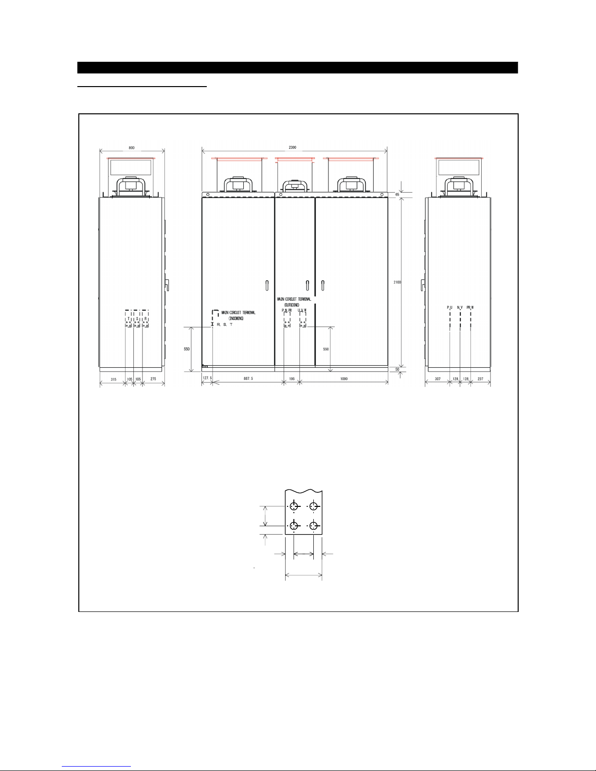
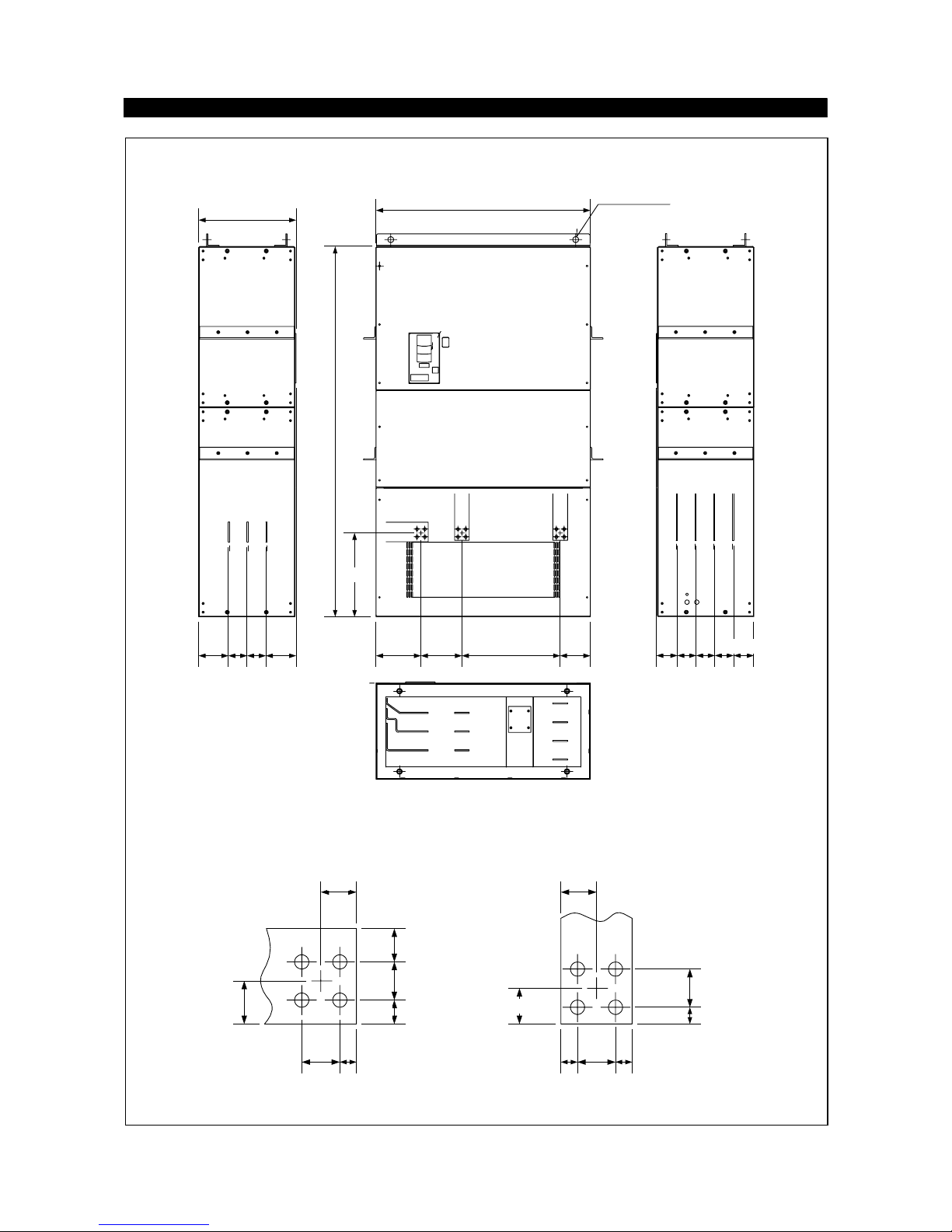
6.1.3 Outline drawings....................................................................................................................44
APPENDICES...................................................................................................................................45
Appendix3............................................................................................................................................47
Appendix4............................................................................................................................................49
Appendix5............................................................................................................................................50
CHAPTER 1
OUTLINE
This chapter gives information on the basic "outline" of this
product.
Always read the instructions in this chapter before using the
equipment.
1.1 Pre-Operation Information
1.2 Basic Configuration
<Abbreviations>
y
DU
Operation panel (FR-DU04)
y
PU
Operation panel (FR-DU04) and parameter unit (FR-PU04)
y
Inverter
Mitsubishi Large Capacity inverter FR-A500L series
y
FR-A500L
Mitsubishi Large Capacity inverter FR-A500L series
y
Pr.
Parameter number
y
PU operation
Operation using the PU (FR-DU04/FR-PU04)
y
External operation
Operation using the control circuit signals
y
Combined operation
Operation using both the PU (FR-DU04/FR-PU04) and
external operation
y
MT-A100E
Mitsubishi large capacity inverter MT-A100 series
<EXCELLENT> series
・・・・・・・・・・・・・・・・・・・・・・・・
・・・・・・・・・・・・・・・・・・・
1
2
CHAPTER 1 OUTLINE
CHAPTER 2 INSTALLATION AND WIRING
CHAPTER 3 OPERATION
CHAPTER 4 PARAMETERS
CHAPTER 5 PROTECTIVE FUNCTIONS
CHAPTER 6 SPECIFICATIONS
APPENDICES
1
1.1 Pre-Operation Information
OUTLINE
1
1.1.1 Precautions for operation
Incorrect handling might cause the inverter to operate improperly, its life to be reduced considerably, or at the
worst, the inverter to be damaged. Handle the inverter properly in accordance with the information in each
section as well as the precautions and instructions of this manual to use it correctly.
This manual is written for the FR-A500L series large capacity inverters.
For handling information on the parameter unit (FR-PU04), inboard options, stand-alone options, etc., refer to
the corresponding manuals.
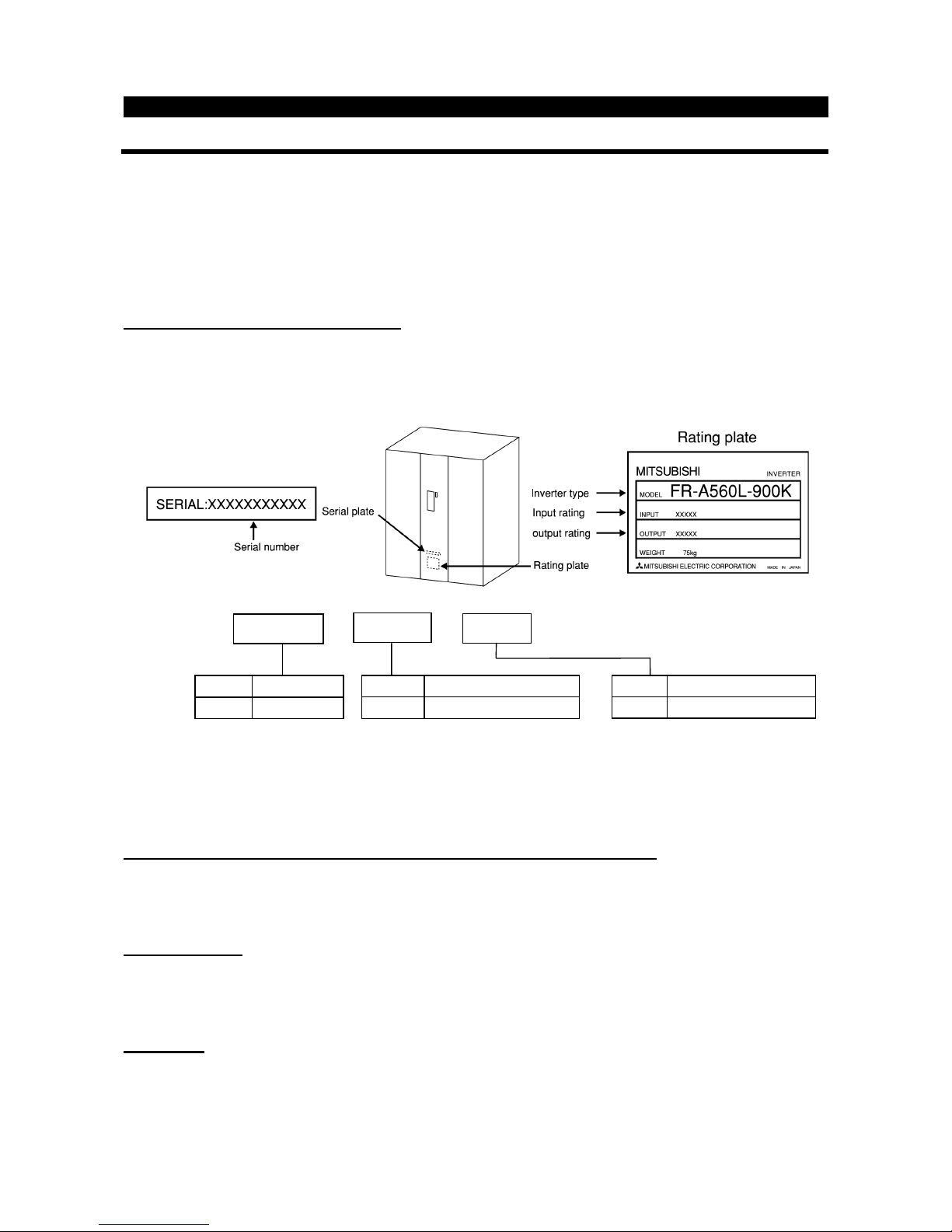
(1)
Unpacking and product check
Unpack the inverter and check the capacity plate on the front cover and the rating plate on the inverter side
face to ensure that the product agrees with your order and the inverter is intact
1) Inverter type
2) Accessory
Instruction manual
If you have found any discrepancy, damage, etc., please contact your sales representative.
(2)
Preparations of instruments and parts required for operation
Instruments and parts to be prepared depend on how the inverter is operated. Prepare equipment and parts
as necessary.
(3)
Installation
To operate the inverter with high performance for a long time, install the inverter in a proper place, in a
correct direction, and with proper clearances.
(4)
Wiring
Connect the power supply, motor and operation signals (control signals) to the terminal block. Note that
incorrect connection may damage the inverter and peripheral devices. (See page 8.)
Symbol Specifications
NA U.S. specifications
Symbol Applicable Motor Capacity
900K Indicates capacity in “kW”
Symbol Voltage Class
A560L 600V class
FR - A560L - 900K -
1.2 Basic Configuration
OUTLIN
E
2
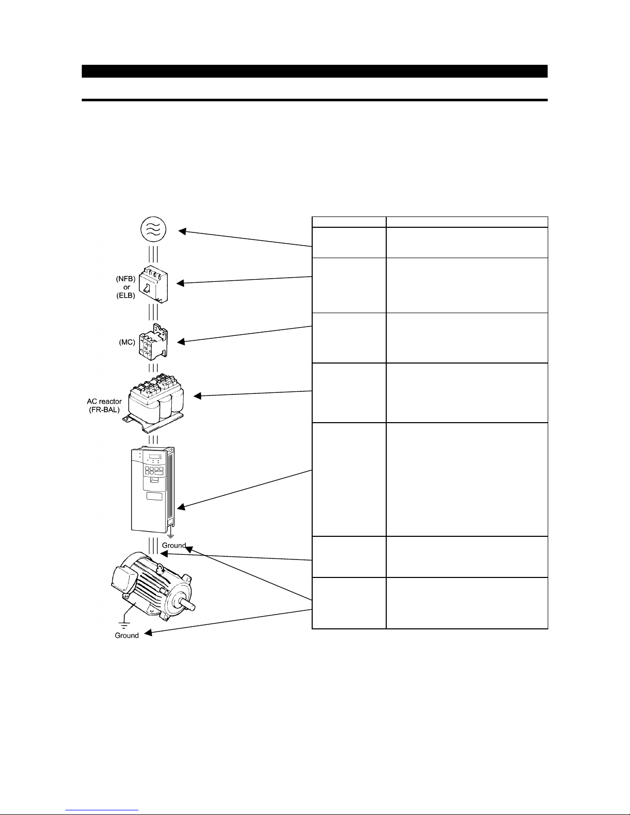
1.2.1 Basic configuration
The following devices are required to operate the inverter. Proper peripheral devices must be selected and
correct connections made to ensure proper operation. Incorrect system configuration and connections can
cause the inverter to operate improperly, its life to be reduced considerably, and in the worst case, the
inverter to be damaged.
Please handle the inverter properly in accordance with the information in each section as well as the
precautions and instructions of this manual. (For connections of the peripheral devices, refer to the
corresponding manuals.)
Name
Description
Power supply
Use the power supply within the permissible
power supply specifications of the inverter.
Earth leakage
circuit breaker
(ELB) or no-fuse
breaker (NFB)
The breaker should be selected with care
since a large inrush current flows in the
inverter at power on.
The breaker must have overcurrent
protection and earth leakage protection.
Magnetic
contactor
The magnetic contactor need not be
provided. When installed, do not use
it to start or stop the inverter. It might reduce
the inverter life.
Reactors
The reactors must be used when the power
factor is to be improved or the inverter is
installed near a large power supply system
(ten times or more of Inverter Output, and
wiring distance within 10m (32.81 feet) ).
Make selection carefully.
Inverter
z
The inverter life is influenced by ambient
temperature. The ambient temperature
should be as low as possible within the
permissible range.
This must be noted especially when the
inverter is installed in an enclosure.
z
Incorrect wiring might lead to inverter
damage. The control signal lines must be
kept fully away from the main circuit to
protect them from noise.
Devices
connected to the
output
Do not connect a power capacitor, surge
suppressor or radio noise filter to the output
side.
Ground
To prevent an electric shock, always ground
the motor and inverter.

CHAPTER 2
INSTALLATION AND WIRING
This chapter gives information on the basic "installation and
wiring" of this product.
Always read the instructions in this chapter before using the
equipment.
2.1 Installation
2.2 Wiring
・・・・・・・・・・・・・・・・・・・・・・・・・・・・・・・・
・・・・・・・・・・・・・・・・・・・・・・・・・・・・・・・・・・・・
CHAPTER 1 OUTLINE
CHAPTER 2 INSTALLATION AND WIRING
CHAPTER 3 OPERATION
CHAPTER 4 PARAMETERS
CHAPTER 5 PROTECTIVE FUNCTIONS
3
5
CHAPTER 6 SPECIFICATIONS
APPENDICES
2

2.1 Installation
INSTALLATION AND WIRING
3
2.1.1 Instructions for installation
1) Handle the unit carefully.
The inverter uses plastic parts. Handle it gently to protect it from damage. Also, hold the unit with even strength
and do not apply too much strength to the front cover alone.
2) Install the inverter where it is not subjected to vibration.
Note the vibration of a cart, press, etc.
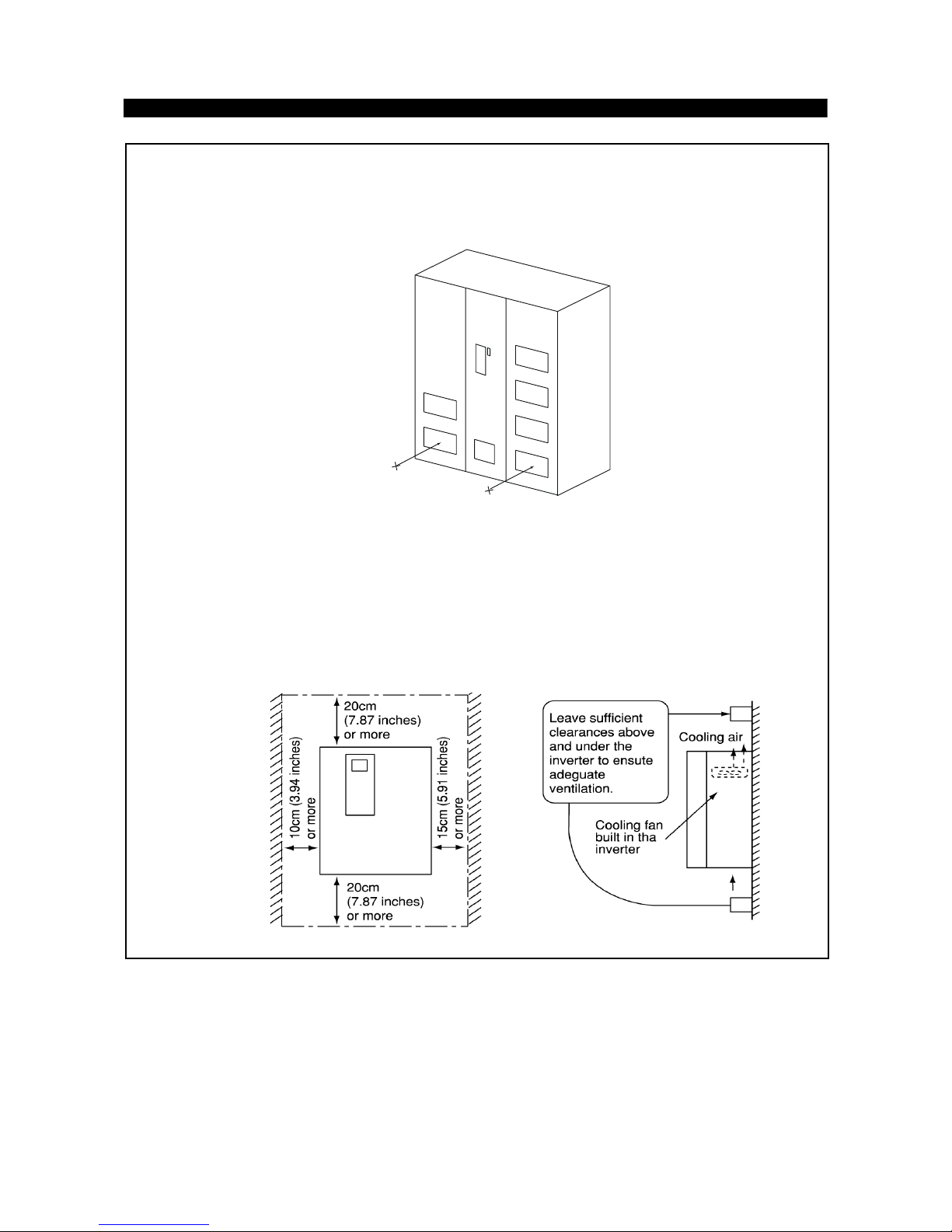
3) Note on ambient temperature
The inverter life is under great influence of ambient temperature. In the place of installation, ambient temperature
must be within the permissible range (-10°C to +40°C (14°F to 104°F) ). Check that the ambient temperature is
within that range in the positions shown in figure 3).
*For FR-A560L-375, 450K at constant torque (CT) rating maximum ambient temperature can be 50°C (122°F).
4) Install the inverter on a non-combustible surface.
The inverter will be very hot (maximum. about 150°C (302°F) ). Install it on a non-combustible surface (e.g.
metal). Also leave sufficient clearances around the inverter.
5) Avoid high temperature and high humidity.
Avoid places where the inverter is subjected to direct sunlight, high temperature and high humidity.
Note: The cooling section outside the enclosure has the cooling fan. Do not use the inverter in any environment
where it is exposed to waterdrops, oil mist, dust, etc.
6) Avoid places where the inverter is exposed to oil mist, flammable gases, fluff, dust, dirt, etc.
Install the inverter in a clean place or inside a "totally enclosed" panel which does not accept any suspended
matter.
7) Note the cooling method when the inverter is installed in an enclosure.
When an inverter is mounted in an enclosure, the ventilation fans of the inverter and enclosure must be carefully
positioned to keep the ambient temperature of the inverter below the permissible value. If they are installed in
improper positions, the rise in ambient temperature will result in reduced performance of the inverter.
8) Secure the inverter vertically, with bolts.
Install the inverter on an installation surface securely and vertically with screws or bolts.
INSTALLATION AND WIRING
4
3) Note on ambient temperatures
FR-A560L-530〜900K
40°C at 5cm (1.97 inch)
FR-A560L-375, 450K
2.2 Wiring
INSTALLATION AND WIRING
5
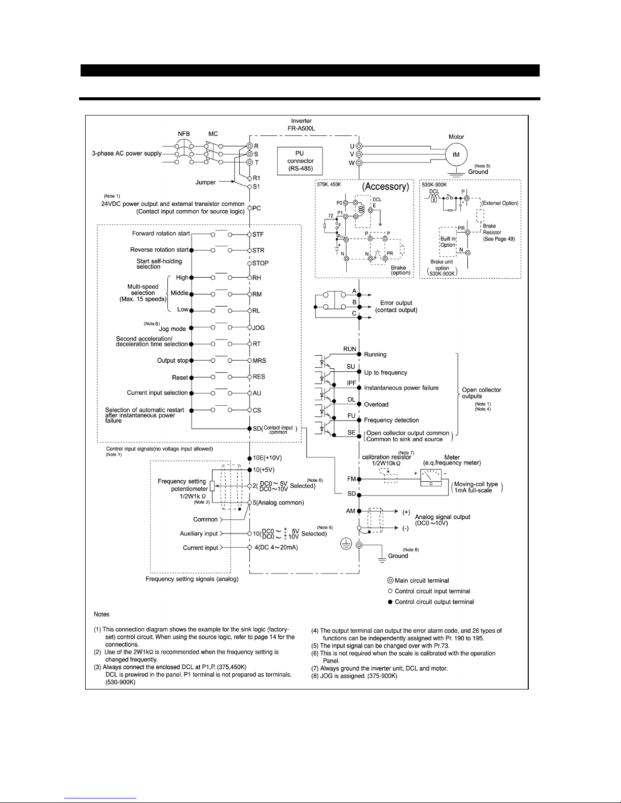
2.2.1 Terminal connection diagram
INSTALLATION AND WIRING
6
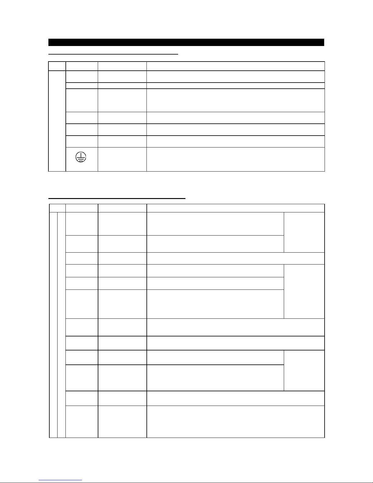
(1)
Description of main circuit terminals
Type
Symbol
Terminal Name
Description
R, S, T
<L
1
, L2, L3>
AC power input
Connect to the commercial power supply. Keep these terminals unconnected when
using the high power factor converter (MT-HC).
U, V, W Inverter output Connect a three-phase squirrel-cage motor.
R1, S1
<L
11
, L21>
Power supply for
control circuit
Connected to the AC power supply terminals R and S. To retain the alarm display
and alarm output or when using the high power factor converter (MT-HC), remove
the jumpers from terminals R-R1 and S-S1 and apply external power to these
terminals.
P, N
<+,->
Optional converter
connection
Connect the optional power return converter (MT-RC) or high power factor converter
(MT-HC).
P, P1
DC reactor
connection
Connect the enclosed DC reactor. (375, 450K)
DC reactor is prewired in 530-900K sizes.
P, PR
<+, PR>
Brake resistor
connection
Connect the optional FR-BR5 brake resistor.
Main
circuit
Ground For grounding the inverter chassis. Must be earthed.
Note:<>Terminal names in parentheses are those of the EC version.
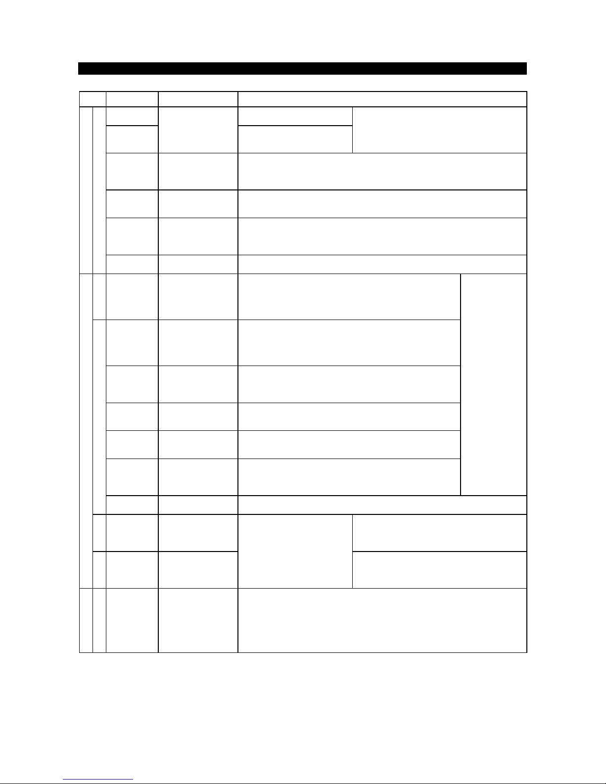
(2)
Description of control circuit terminals
Type
Symbol
Terminal Name
Description
STF Forward rotation start
Turn on the STF signal to start forward rotation and turn it off to
stop. Acts as a programmed operation start signal in the
programmed operation mode. (Turn on to start and turn off to
stop.)
STR Reverse rotation start
Turn on the STR signal to start reverse rotation and turn it off to
stop.
When the STF
and STR signals
are turned on
simultaneously,
the stop
command is
given.
STOP
Start self-holding
selection
Turn on the STOP signal to select the self-holding of the start signal.
RH,RM,RL Multi-speed selection
Use the RH, RM and RL signals as appropriate to select multiple
speeds.
(JOG) JOG mode selection
This terminal connected internally, can not be used by the
customer. (530-900KW :this signal is assigned in Factory.)
RT
Second acceleration/
deceleration time
selection
Turn on the RT signal to select the second acceleration/
deceleration time. W hen the second functions such as "second
torque boost" and "second V/F (base frequency)" functions have
been set, these functions can also be selected by turning on the
RT signal.
Input terminal
function selection
(Pr. 180 to
Pr. 186) change
terminal
functions.
MRS Output stop
Turn on the MRS signal (20ms or longer) to stop the inverter output.
Used to shut off the inverter output to bring the motor to a stop by the magnetic
brake.
RES Reset
Used to reset the protective circuit activated. Turn on the RES signal for more than
0.1 sec, then turn it off.
AU
Current input
selection
Only when the AU signal is turned on, the inverter can be
operated with the 4-20mADC frequency setting signal.
CS
Automatic restart after
instantaneous power
failure selection
With the CS signal on, restart can be made automatically when
the power is restored after an instantaneous power failure. Note
that this operation requires restart parameters to be set. When
the inverter is shipped from the factory, it is set to disallow restart.
Input terminal
function selection
(Pr. 180 to Pr.
186) change
terminal
functions.
SD
Contact input
common (sink)
Common terminal for the terminal FM.
Common output terminal for 24VDC 0.1A power (PC terminal).
Input signals
Contacts, e.g. start, function setting
PC
24VDC power and
external transistor
common
Contact input
common (source)
When transistor output (open collector output), such as a programmable controller, is
connected, connect the external power supply common for transistor output to this
terminal to prevent a fault caused by leakage current. This terminal can be used as a
24VDC, 0.1A power output. When source logic has been selected, this terminal
serves as a contact input common.
INSTALLATION AND WIRING
7
Type
Symbol
Terminal Name
Description
10E
10VDC, permissible load current
10mA10Frequency setting
power supply
5VDC, permissible load current
10mA
When the frequency setting potentiometer is
connected in the factory-set state, connect it to
terminal 10.
When it is connected to terminal 10E, change the
input specifications of terminal 2.
2
Frequency setting
(voltage)
By entering 0 to 5VDC (0 to 10VDC), the maximum output frequency is reached at
5V (or 10V) and I/O are proportional. Switch between input 0 to 5VDC (factory
setting) and 0 to 10VDC from operation terminal. Input resistance 10kΩ. Maximum
permissible voltage 20V.
4
Frequency setting
(current)
By entering 4 to 20mADC, the maximum output frequency is reached at 20mA and
I/O are proportional. This input signal is valid only when the AU signal is on. Input
resistance 250Ω. Maximum permissible current 30mA.
1
Auxiliary frequency
setting
By entering 0 to ±5VDC 0 to ±10VDC, this signal is added to the frequency setting
signal of terminal 2 or 4. Switch between input 0 to ±5VDC and 0 to ±10VDC
(factory setting) from operation terminal. Input resistance 10kΩ. Maximum
permissible voltage ±20V.
Input signals
Analog frequency setting
5
Frequency setting
input common
Common to the frequency setting signal (terminal 2, 1 or 4) and analog output
terminal AM. Do not earth.
Contact
A,B,C
Alarm output
Change-over contact output indicating that the output has been
stopped by the inverter protective function activated.
200VAC 0.3A, 30VDC 0.3A. Alarm: discontinuity across B-C
(continuity across A-C), normal: continuity across B-C
(discontinuity across A-C).
RUN
Inverter running
Switched low when the inverter output frequency is equal to or
higher than the starting frequency (factory set to 0.5Hz,
variable).
Switched high during stop or DC dynamic brake operation
(note1)
Permissible load 24VDC 0.1A.
SU
Up to frequency
Switched low when the output frequency has reached within
±
10% of the set frequency (factory setting, variable). Switched
high during acceleration, deceleration or stop
(note 1)
. Permissible
load 24VDC 0.1A.
OL
Overload alarm
Switched low when the stall prevention function has caused
stall prevention to be activated. Switched high when stall
prevention is reset
(note 1)
. Permissible load 24VDC 0.1A.
IPF
Instantaneous power
failure
Switched low when instantaneous power failure or
undervoltage protection is activated
(note 1)
. Permissible load
24VDC 0.1A.
FU
Frequency detection
Switched low when the output frequency has reached or
exceeded the detection frequency set as appropriate. Switched
high when below the detection frequency
(note 1)
. Permissible load
24VDC 0.1A
Output terminal
function selection
(Pr. 190 to Pr.
195) change
terminal
functions.
Open collector
SE
Open collector output
common
Common to the RUN, SU, OL, IPF and FU terminals.
Pulse
FM
For meter
Factory setting of output item:
Frequency
Permissible load current 1mA
1440 pulses/second. at 60Hz
Output signals
Analog
AM
Analog signal output
One selected from 16 monitoring
items, such as output
frequency, is output
(note 2)
.
The output signal is proportional
to the magnitude of each
monitoring item.
Factory setting of output item:
Frequency
Output signal 0 to 10VDC
Permissible load current 1mA
Communication
RS485
PU connector
With the operation panel connector, communication can be made through RS-485.
·
Conforming Standard : EIA Standard RS-485
·
Transmission format : Multi-drop link
·
Communication speed : Maximum 19200 baud rates
·
Overall length : 500m
Note1: Low indicates that the open collector outputting transistor is on (conducts). High indicates that the
transistor is off (does not conduct).
Note2: Not output while the inverter is reset.

INSTALLATION AND WIRING
8
2.2.2 Wiring of the main circuit
(1)
Wiring instructions
1) Power must not be applied to the output terminals (U, V, W) of the inverter. Otherwise the inverter will be
damaged.
2) After wiring, wire off-cuts must not be left in the inverter.
Wire off-cuts can cause an alarm, failure or malfunction. Always keep the inverter clean.
3) Use thick cables to make a voltage drop of 2% or less.
If the wiring distance is long between the inverter and motor, a main circuit cable voltage drop will cause the
motor torque to decrease especially at the output of a low frequency.
4) Electromagnetic wave interference
The input/output (main circuit) of the inverter includes harmonic components, which may interfere with the
communication devices (such as AM radios) used near the inverter. In this case, use shielded wire cables as
the power cable.
5) Do not install a power capacitor, surge suppressor or radio noise filter (FR-BIF option) in the output side of the
inverter.
This will cause the inverter to trip or the capacitor and surge suppressor to be damaged. If any of the above
devices are installed, immediately remove them.
6) When rewiring after operation, make sure that the POWER lamp has gone off, and when more than 10minutes
have elapsed after power-off, check with a tester that the DC bus voltage is zero. After that, start rewiring work.
For some time after power-off, there is a dangerous voltage in the capacitor.
7) Top attachments should be removed before operating because of Air exhaust. Side attachments can be used
for fixing the unit. (See page 44)
Notes on Grounding
• Leakage currents flow in the inverter. To prevent an electric shock, the inverter and motor must be grounded
(grounding resistance: 10Ω or less.)
• Use the dedicated ground terminal to ground the inverter. (Do not use the screw in the case, chassis, etc.)
• The ground cable should have a thickness of 38mm2, or more, and be as short as possible. The grounding
point should be as close to the inverter as possible.
INSTALLATION AND WIRING
9
(2)
Terminal block layout
In the main circuit of the inverter, the terminals are arranged as shown below:
FR-A560L-530K〜900K
Left Side
Front
Right Side
MAIN CIRCUIT TERMINAL (Detail)
75
40
17.5
4017.5 17.5
Units
<mm>
INSTALLATION AND WIRING
10
FR-A560L-375K, 450K
P0WVU
108 96 96 96 104
P1 N P
TSR
P0
W
V
U
P1
N
P
T
S
R
1569696152
430
505210
230
155
Rg[ pl
4 - 30
500
1100
1900
(Bottom View)
4‑φ 30
U, V, W, P0
P1, P, N
[q
R, S, T
45
37.5
37.5
40
17.5
40
17.517.5 40
35
35
40
17.5
40
[q
Units<mm
>
TERMINAL (Detail
)
TERMINAL (Detail
)
INSTALLATION AND WIRING
11
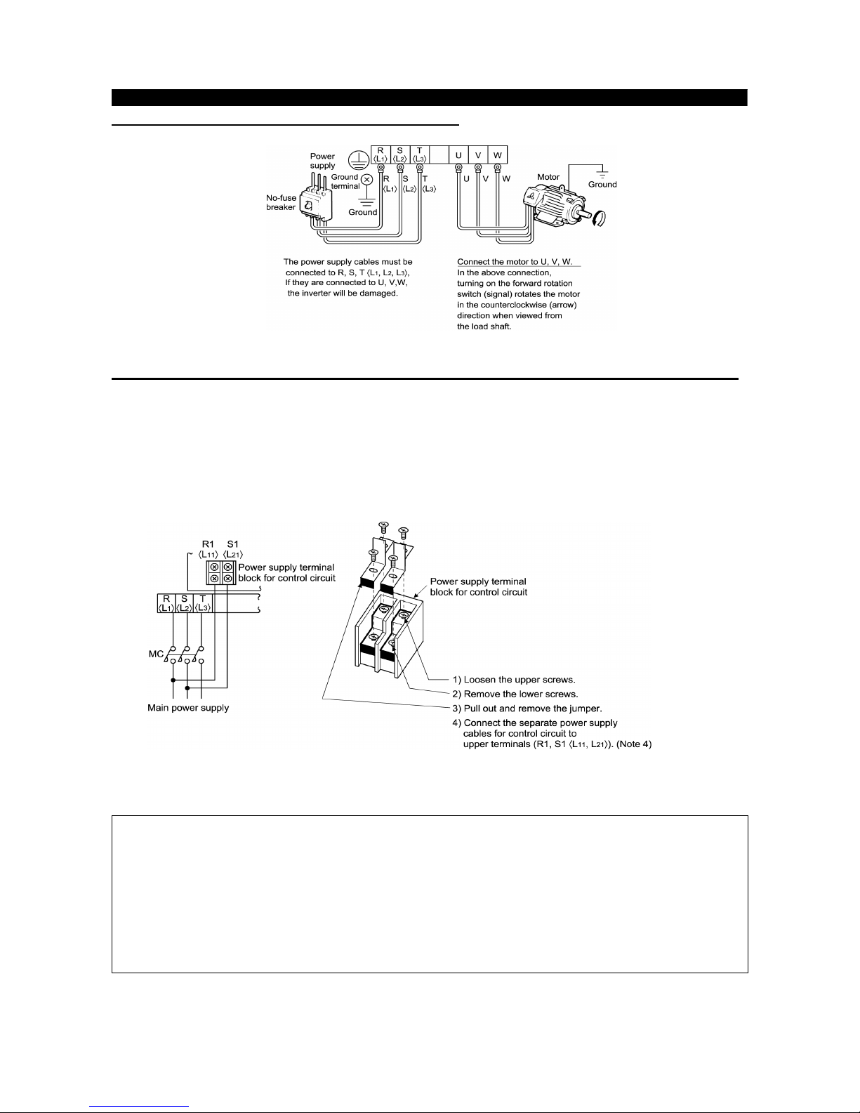
(3)
Connection of the power supply and motor
(4)
Connecting the control circuit to a power supply separately from the main circuit
If the magnetic contactor (MC) in the inverter power supply is opened when the protective circuit is operated,
the inverter control circuit power is lost and the alarm output signal cannot be kept on. To keep the alarm
signal on terminals R1 and S1 are available. In this case, connect the power supply terminals R1 and S1 <L
11
and L
21
> of the control circuit to the primary side of the MC.
<Connection procedure>
Note: 1. W hen the main circuit power (R, S, T) <L
1
, L2, L3,> is on, do not switch off the control power
(terminals R1, S1<L
11
, L21>). Otherwise the inverter may be damaged.
2. W hen using a separate power supply, the jumpers across R-R1 and S-S1 <L
1-L11
and
L
2-L21
>must be removed. Otherwise the inverter may be damaged.
3. For a different power supply system which takes the power of the control circuit from other than
the primary side of the MC, the voltage should be equal to the main circuit voltage.
4. The power supply cables must not be connected to the lower terminals. If connected, the inverter
may be damaged.
INSTALLATION AND WIRING
12
2.2.3 Wiring of the control circuit
(1)
Wiring instructions
1) Terminals SD, SE and 5 are common to the I/O signals and isolated from each other. These common terminals
must not be connected to each other or earthed.
2) Use shielded or twisted cables for connection to the control circuit terminals and run them away from the main
and power circuits (including the 200V relay sequence circuit).
3) The frequency input signals to the control circuit are micro currents. When contacts are required, use two or
more parallel micro signal contacts or a twin contact to prevent a contact fault.
4) It is recommended to use the cables of 0.75mm2 gauge for connection to the control circuit terminals.
If the cable gauge used is 1.25mm2 or more, the front cover may be lifted when there are many cables running
or the cables are run improperly, resulting in an operation panel or parameter unit contact fault.
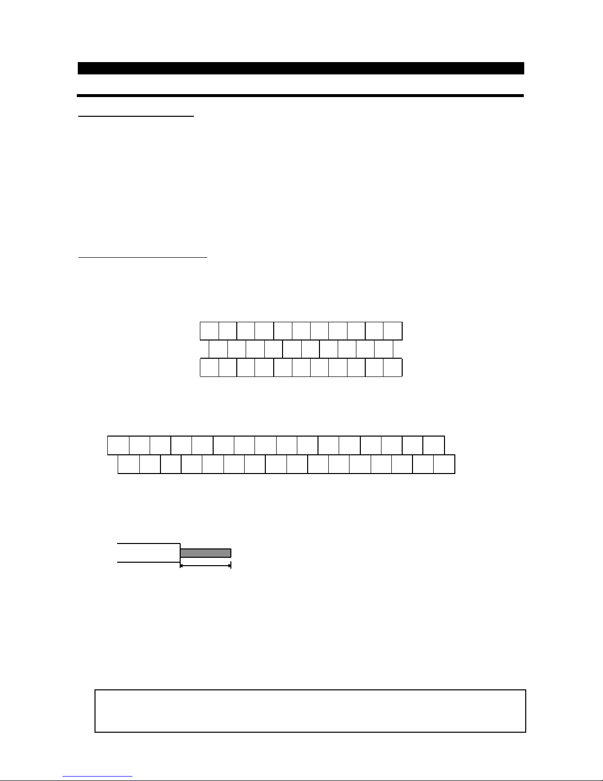
(2)
Terminal block layout
l
NA version(OR Version
)
In the control circuit of the inverter, the terminals are arranged as shown below:
Terminal screw size: M3.5
A
RL
SE RUN SU IPF OL FU SD STF STR JOG CS
RM RH RT AU STOP MRS RES SD FM
B C PC AM 10 E 1 0 2 5 4 1
l
EC version
Terminal screw size : M3
<Wiring procedure>
1) For the wiring of the control circuit, strip the sheaths of the cables and use them as they are.
Strip the sheath to the following dimension. If too much is stripped this may cause a short circuit with
the neighboring cable. If too little stripped this may cause cable disconnection.
6mm ± 1mm
2) Loosen the terminal screw and insert the cable into the terminal.
3) Tighten the screw to the specified torque.
Undertigthening can cause cable disconnection or malfunction. Overtightening can cause a short circuit or
malfunction due to the screw or unit damaged.
Tightening torque : 5 to 6 kgf・cm
Note : Wire the stripped cable by twisting it to prevent it from becoming loose. (Do not plate the cable with
solder.)
Note : 1. Use a NFB (No fuse breakers) or fuse on the inverter input (primary) side.
2. Make sure that the control circuit terminal wiring does not touch power circuit terminals (or
screws) or conducting power circuit.
SE RUN SU LPF OL FU STOP MRS RES PC STF STR JOG CS FM SD
A B C SD AM 10E 10 2 5 4 1 RL RM RH RT AU
 Loading...