

Mitsubishi FDCVA302HENR, FDTCA151R, FDTA151R, FDTVA302HEN1R, FDENVA302HEN1R User Manual
...
Collection data
PACKAGED AIR-CONDITIONER
(Split system, Air to air heat pump type)
CEILING RECESSED TYPE
FDTVA302HEN1R
Manual No. '06•PAC-T-109
CEILING SUSPENDED TYPE
FDENVA302HEN1R
SATELLITE DUCTED TYPE
FDUMVA302HEN2R
MULTI-TYPE (V-MULTI)
PACKAGED AIR-CONDITIONER
(OUTDOOR UNIT)
FDCVA302HENR
(INDOOR UNIT)
FDTCA151R
FDTA151R
FDENA151R
FDKNA151R

-
1
-
TABLE OF CONTENTS
1. PACKAGED AIR-CONDITIONER......................................................................................... 2
2. MULTI-TYPE (V MULTI) PACKAGED AIR-CONDITIONER ............................................ 122
3. WIRELESS KIT (OPTIONAL PARTS) .............................................................................. 190

-
2
-
1. PACKAGED AIR-CONDITIONER
CONTENTS
1.1 GENERAL INFORMATION ............................................................................... 4
1.1.1 Specific features .......................................................................................... 4
1.1.2 How to read the model name....................................................................... 4
1.2 SELECTION DATA ........................................................................................... 5
1.2.1 Specifications ............................................................................................... 5
(1) Ceiling recessed type (FDT) ......................................................................... 5
(2) Ceiling suspended type (FDEN) ................................................................... 6
(3) Satellite ducted type (FDUM)........................................................................ 7
1.2.2 Range of usage & limitations ....................................................................... 8
1.2.3 Exterior dimensions ..................................................................................... 9
(1) Indoor unit ..................................................................................................... 9
(2) Remote controller (Optional parts) ............................................................. 12
(3) Outdoor unit ................................................................................................ 14
1.2.4 Inside view ................................................................................................. 15
1.2.5 Exterior appearance .................................................................................. 16
1.2.6 Piping system ............................................................................................ 17
1.2.7 Selection chart ........................................................................................... 18
1.2.8 Characteristics of fan ................................................................................. 23
1.2.9 Noise level ................................................................................................. 23
(1) Indoor unit ................................................................................................... 23
(2) Outdoor unit ................................................................................................ 24
1.3 ELECTRICAL DATA ....................................................................................... 25
1.3.1 Electrical wiring .......................................................................................... 25
(1) Indoor unit ................................................................................................... 25
(2) Outdoor unit ................................................................................................ 28
1.4 OUTLINE OF OPERATION CONTROL BY MICROCOMPUTER .................. 29
(1) Remote controller ....................................................................................... 29
(2) Operation control function by the indoor unit controller .............................. 31
(3) Operation control function by the wired remote controller .......................... 38
(4) Operation control function by the outdoor unit controller ............................ 39

-
3
-
1.5 APPLICATION DATA ...................................................................................... 49
1.5.1 Installation of indoor unit ........................................................................... 50
(1) Ceiling recessed type (FDT) ....................................................................... 50
(2) Ceiling suspended type (FDEN) ................................................................. 56
(3) Satellite ducted type (FDUM)...................................................................... 61
1.5.2 Installation of wired remote controller ....................................................... 68
1.5.3 Installation of outdoor unit ......................................................................... 69
(1) Installation................................................................................................... 69
(2) Refrigerant piping work ............................................................................... 71
(3) Air tightness test and air purge ................................................................... 72
(4) Refrigerant quantity .................................................................................... 73
(5) Drain piping work ........................................................................................ 73
(6) Electrical wiring ........................................................................................... 74
(7) Setting functions using the wired remote controller .................................... 76
(8) Checking operation data ............................................................................. 80
(9) Test run ....................................................................................................... 81
1.6 MAINTENANCE DATA ................................................................................... 82
1.6.1 Servicing ................................................................................................... 82
1.6.2 Trouble shooting for refrigerant circuit ....................................................... 83
1.6.3 Diagnosing of microcomputer circuit ......................................................... 84
(1) Selfdiagnosis function ................................................................................. 84
(2) Procedures of trouble diagnosis ................................................................. 87
(3) Error diagnosis procedures at the indoor unit side ..................................... 87
(4) Error diagnosis procedures at the outdoor unit side ................................. 104
(5)
Check method in the case of the failure display in the remote controller ..............
119
(6)
Check abnormal operation data with the wired remote controller .........................
120
1.6.4
Check display on wireless specification models (FDEN · FDT)....................
121
-
4
-
Example: FDT V A 30 2 H EN 1 R
1.1 GENERAL INFORMATION
1.1.1 Specific features
(1) A new refrigerant, R410A, which causes no damage to the earth’s ozone layer, is used. R410A is a pseudoazeotropic refrigerant, so
there is little formation of separate vapor and liquid layers, and it is possible to add refrigerant on-site.
(2) Less refrigerant charge amount due to use of double phase refrigerant flow system. The total refrigerant charge amount has been
reduced by more than 50%.
(3) The microcomputer chip is installed in the indoor unit and outdoor unit. There is no need for the unit to communicate between the
outdoor and indoor units so the unit is more resistant to electromagnetic noise thus the incidence of microcomputer malfunction
has been reduced. The compressor in the outdoor unit has its own self protection function, that reacts according to abnormal high
pressure and excessive high temperature.
(4) There are only three power lines between the outdoor and indoor unit. One cabtyre cable with 3 wires encased in one sheath is
enough for conducting the wiring work between the outdoor unit and the indoor unit. This contributes to simpler wiring work in the
field.
(5) All air supply ports have auto swing louvers. (Only case of FDT and FDEN models). The indoor fan motor has three speeds of
high, medium and low.
(6) All models have service valves protruding from the outdoor unit for faster flare connection work in the field.
(7) The size and weight of the outdoor units in the FDCVA 302 series have been greatly reduced. Use of an inverter has also improved
energy conservation and economy.
1.1.2 How to read the model name
RoHS specification
Applicable power source ... See the specifications
Heat pump type
Series No.
Product capacity
R410A models
V: Inverter specification
Model name
FDT :
FDEN :
FDUM
:
FDC :
Ceiling recessed type unit with wired
remote controller
Ceiling suspended type unit with
wireless remote controller
Satellite ducted type unit with wired
remote controller
Outdoor unit
-
5
-
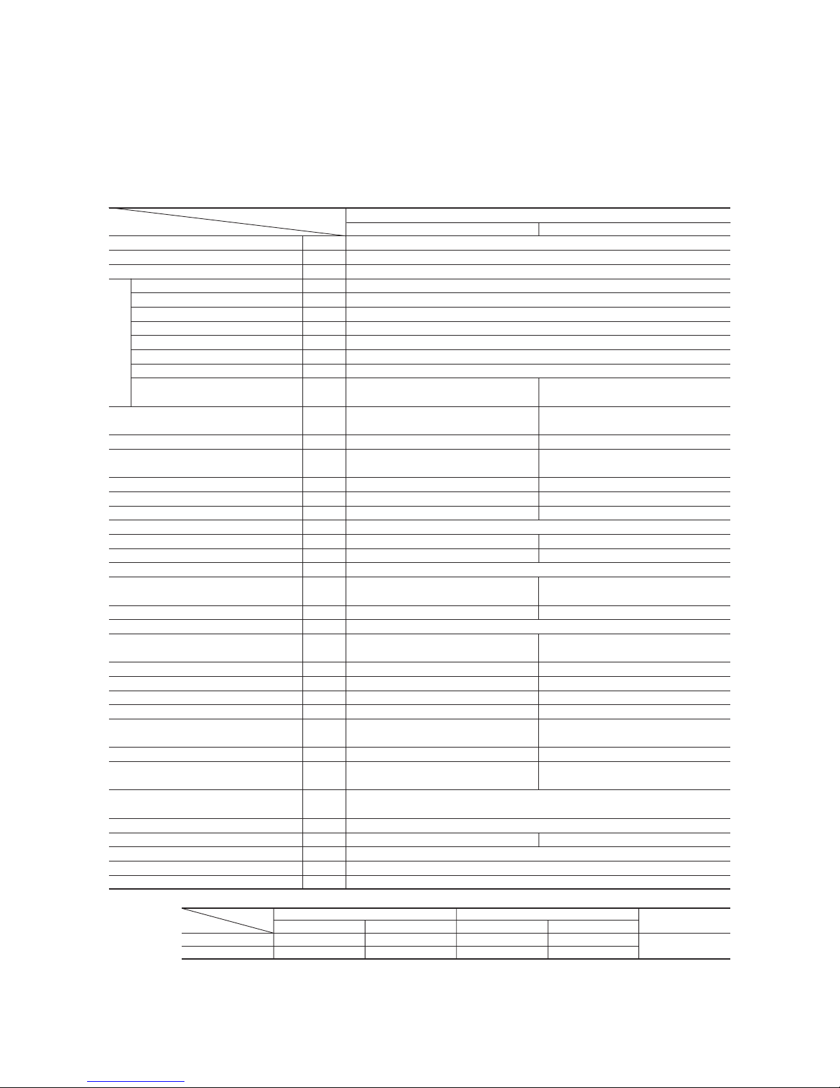
Item
Model
FDTA301R FDCVA302HENR
Nominal cooling capacity
(1)
kW 7.1[3.9~8.0]
Nominal heating capacity
(1)
kW 8.0[4.0~9.0]
Power source 1 Phase, 220/230/240V 50Hz
Cooling power consumption kW 1.90
Running current (Cooling) A 8.3
Power factor (Cooling) % 99
Heating power consumption kW 2.07
Running current (Heating) A 9.0
Power factor (Heating) % 99
Inrush current (L.R.A) A 5
Noise level dB(A)
35 52
Exterior dimensions
mm
Unit 270 × 840 × 840
750 × 880 (+88) × 340
Height × Width × Depth Panel 30 × 950 × 950
Net weight kg 31 (Unit:24 Panel:7) 60
Refrigerant equipment
– 2YC45DXD 1
Compressor type & Q’ty
Starting method – Direct line start
Heat exchanger Louver fin & inner grooved tubing Straight fin & inner grooved tubing
Refrigerant control – Electronic expansion valve
Refrigerant R410A
Quantity kg –
2.95 [Pre-charged up to the piping length of 30m]
Refrigerant oil r – 0.65 (FVC50K)
Defrost control Microcomputer controlled de-icer
Air handling equipment
Fan type & Q’ty
Turbo fan × 1 Propeller fan × 1
Motor W 20 × 1 120 × 1
Starting method Direct line start
Air flow CMM Cooling:60 Heating:48.5
Outside air intake Available –
Air filter, Q’ty Long life filter ×1(washable) –
Shock & vibration absorber Rubber sleeve (for fan motor) Rubber mount (for compressor)
Electric heater W – 20 (Crank case heater)
Operation control Wired remote control switch (Optional : RC-E1R)
Operation switch
Wireless remote control switch (Optional : RCN-T-35W-ER)
– (Indoor unit side)
Room temperature control Thermostat by electronics –
Safety equipment Internal thermostat for fan motor. Internal thermostat for fan motor.
Frost protection thermostat. Abnormal discharge temperature protection.
Installation data mm
Liquid line: φ9.52 (3/8″) Gas line: φ15.88 (5/8″)
Refrigerant piping size (in)
Connecting method Flare piping
Drain hose Connectable with VP25 (I.D.25mm, O.D.32mm) –
Insulation for piping Necessary (both Liquid & Gas lines)
Accessories Mounting kit. Drain hose
Optional parts Decorative Panel
Operation data
(3)
(2) This packaged air-conditioner is manufactured and tested in conformity with the following standard. ISO-T1 “UNITARY AIR-CONDITIONERS”
(3) The operation data indicate when the air-conditioner is operated at 230V 50Hz.
Notes (1) The data are measured at the following conditions.
Item Indoor air temperature Outdoor air temperature
Standards
Operation DB WB DB WB
Cooling 27˚C 19˚C 35˚C 24˚C
Heating 20˚C – 7˚C 6˚C
ISO-T1
FDTVA302HEN1R
Model FDTVA302HEN1R
Powerful mode Hi:38 Me:35 Lo:33
Mild mode Hi:35 Me:33 Lo:31
Powerful mode Hi:20 Me:17 Lo:15
Mild mode Hi:17 Me:15 Lo:13
48
(1) Ceiling recessed type (FDT)
1.2 SELECTION DATA
1.2.1 Specifications

-
6
-
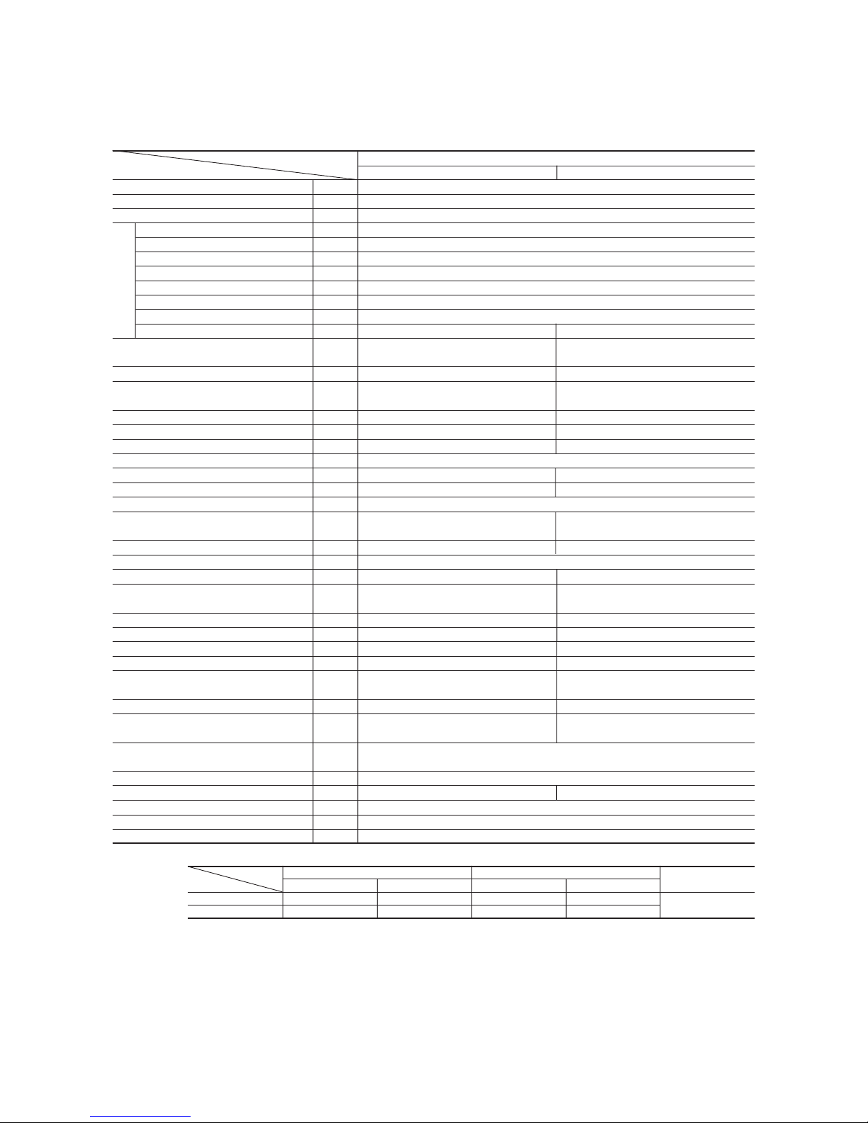
Item
Model
FDENA301R FDCVA302HENR
Nominal cooling capacity
(1)
kW 7.1[3.5~8.0]
Nominal heating capacity
(1)
kW 8.0[4.0~9.0]
Power source 1 Phase, 220/230/240V 50Hz
Cooling power consumption kW 2.06
Running current (Cooling) A 9.1
Power factor (Cooling) % 98
Heating power consumption kW 2.21
Running current (Heating) A 9.8
Power factor (Heating) % 98
Inrush current (L.R.A) A 5
Noise level dB(A)
Exterior dimensions
mm 210 × 1320 × 690 750 × 880 (+88) × 340
Height × Width × Depth
Net weight kg 36 60
Refrigerant equipment
– 2YC45DXD 1
Compressor type & Q’ty
Starting method – Direct line start
Heat exchanger Louver fin & inner grooved tubing Straight fin & inner grooved tubing
Refrigerant control – Electronic expansion valve
Refrigerant R410A
Quantity kg –
2.95 [Pre-charged up to the piping length of 30m]
Refrigerant oil r – 0.65 (FVC50K)
Defrost control Microcomputer controlled de-icer
Air handling equipment
Fan type & Q’ty
Multiblade centrifugal fan × 4 Propeller fan × 1
Motor W 25 × 2 120 × 1
Starting method Direct line start
Air flow CMM Cooling:60 Heating:48.5
Outside air intake Unavailable –
Air filter, Q’ty Polypropylene net ×2(washable) –
Shock & vibration absorber Rubber sleeve (for fan motor) Rubber mount (for compressor)
Electric heater W – 20 (Crank case heater)
Operation control
Wireless remote control switch (Optional: RCN-E1R)
Operation switch Wired remote control switch (Optional: RC-E1R)
– (Indoor unit side)
Room temperature control Thermostat by electronics –
Safety equipment Internal thermostat for fan motor. Internal thermostat for fan motor.
Frost protection thermostat. Abnormal discharge temperature protection.
Installation data mm
Liquid line: φ9.52 (3/8″) Gas line: φ15.88 (5/8″)
Refrigerant piping size (in)
Connecting method Flare piping
Drain hose Connectable with VP20 (I.D.20mm, O.D.26mm) –
Insulation for piping Necessary (both Liquid & Gas lines)
Accessories Mounting kit. Drain hose
Optional parts –
Model FDENVA302HEN1R
Operation data
(3)
(2) This packaged air-conditioner is manufactured and tested in conformity with the following standard. ISO-T1 “UNITARY AIR-CONDITIONERS”
(3) The operation data indicate when the air-conditioner is operated at 230V 50Hz.
Notes (1) The data are measured at the following conditions.
Item Indoor air temperature Outdoor air temperature
Standards
Operation DB WB DB WB
Cooling 27˚C 19˚C 35˚C 24˚C
Heating 20˚C – 7˚C 6˚C
ISO-T1
FDENVA302HEN1R-SB
48
Powerful mode Hi:44 Me:41 Lo:39
Mild mode Hi:41 Me:39 Lo:38
Powerful mode Hi:20 Me:18 Lo:14
Mild mode Hi:18 Me:14 Lo:12
(2) Ceiling suspended type (FDEN)
-
7
-
Model FDUMVA302HEN2R
Item
Model
FDUMA302R FDCVA302HENR
Nominal cooling capacity
(1)
kW 7.1[3.5~8.0]
Nominal heating capacity
(1)
kW 8.0[4.0~9.0]
Power source 1 Phase, 220/230/240V, 50Hz
Cooling power consumption kW 2.08
Running current (Cooling) A 9.2
Power factor (Cooling) % 98
Heating power consumption kW 2.21
Running current (Heating) A 10.2
Power factor (Heating) % 94
Inrush current (L.R.A) A 5
Noise level dB(A) Hi:35 Me:32 Lo:29
Exterior dimensions
mm 299 × 950 × 635 750× 880 (+88)× 340
Height × Width × Depth
Net weight kg 40 60
Refrigerant equipment
–
2YC45DXD × 1
Compressor type & Q’ty
Starting method – Direct line start
Heat exchanger Louver fin & inner grooved tubing Straight fin & inner grooved tubing
Refrigerant control – Electronic expansion valve
Refrigerant R410A
Quantity kg –
2.95 [Pre-charged up to the piping length of 30m]
Refrigerant oil r – 0.48 (BR68A)
Defrost control Microcomputer controlled de-icer
Air handling equipment
Fan type & Q’ty
Multiblade centrifugal fan × 2 Propeller fan × 1
Motor W 100 × 1 120 × 1
Starting method Direct line start
Air flow CMM Hi: 20 Me:18 Lo:15 Cooling:60 Heating:48.5
Available static pressure
Pa Standard: 50, Max: 85 –
Outside air intake – –
Air filter, Q’ty – –
Shock & vibration absorber Rubber sleeve (for fan motor) Rubber mount (for compressor)
Electric heater W – 20(Crank case heater)
Operation control Wired remote control switch (Optional: RC-E1R)
Operation switch Wireless kit (Optional: RCND-KIT-HER)
– (Indoor unit side)
Room temperature control Thermostat by electronics –
Safety equipment Internal thermostat for fan motor. Internal thermostat for fan motor.
Frost protection thermostat. Abnormal discharge temperature protection.
Installation data mm
Liquid line: φ9.52 (3/8″) Gas line: φ15.88 (5/8″)
Refrigerant piping size (in)
Connecting method Flare piping
Drain hose Connectable with VP25 (I.D.25mm, O.D.32mm) –
Insulation for piping Necessary (both Liquid & Gas lines)
Accessories Mounting kit. Drain hose
Optional parts Filter kit (UM-FL2E)
(2) This packaged air-conditioner is manufactured and tested in conformity with the following standard.
ISO-T1 “UNITARY AIR-CONDITIONERS”
(3) The operation data indicate when the air-conditioner is operated at 230V 50Hz.
Notes (1) The data are measured at the following conditions.
Item Indoor air temperature Outdoor air temperature
Standards
Operation DB WB DB WB
Cooling 27˚C 19˚C 35˚C 24˚C
Heating 20˚C – 7˚C 6˚C
ISO-T1
Operation data
(3)
FDUMVA302HEN2R
48
(3) Satellite ducted type (FDUM)
-
8
-
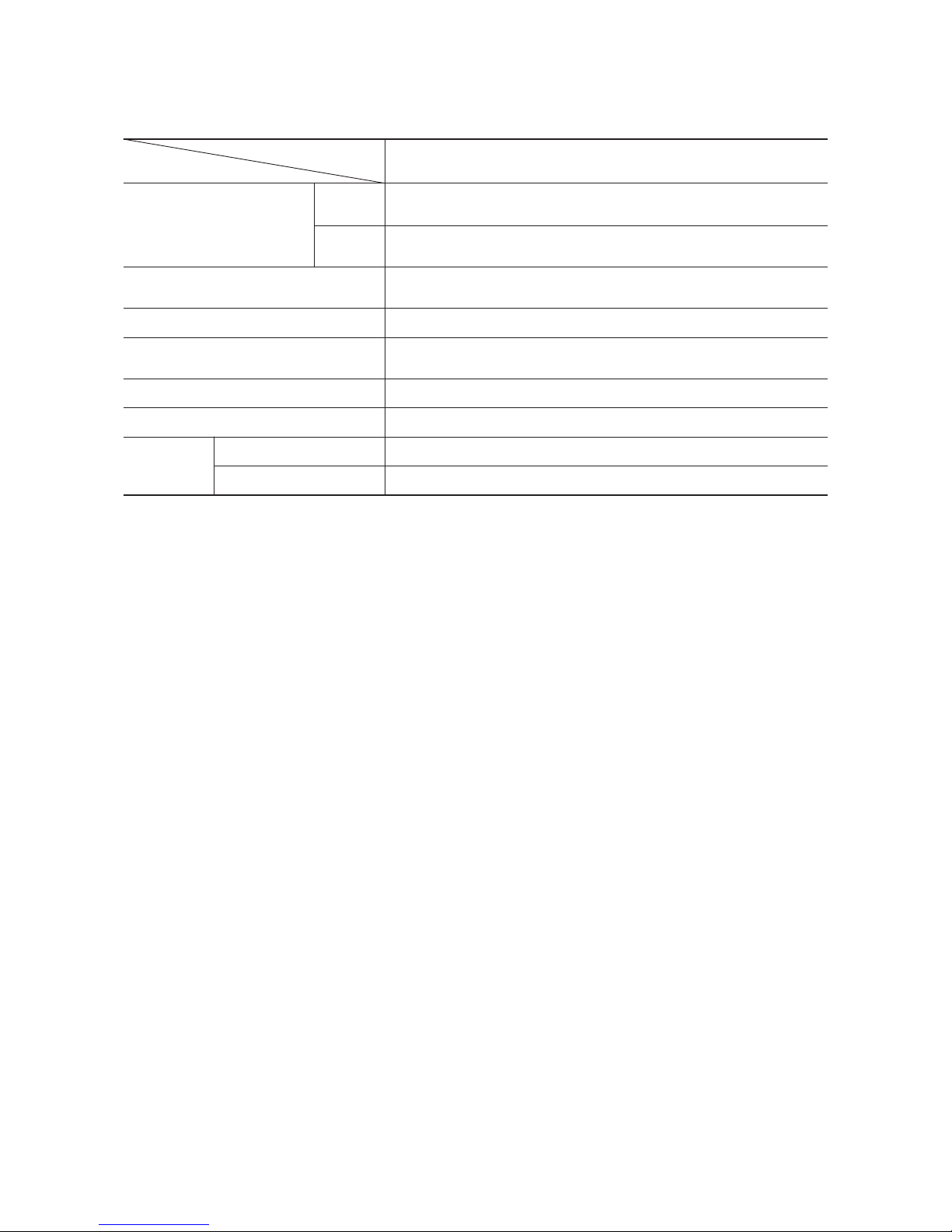
1.2.2 Range of usage & limitations
Model
302 series
Item
Limitations
Return air temp
Indoor unit atmosphere (behind ceiling)
temperature and humidity
Refrigerant line (one way) length
Vertical height difference between
outdoor unit and indoor unit
Power source voltage
Voltage at starting
Cycle Time
Stop Time
Dew point temperature: 28˚C or less, relative humidity: 80% or less
Indoor unit:18~30˚CD.B Outdoor unit:-15~43˚CD.B
Max. 50m
7 minutes or more (4 minutes or more from start to stop) or (3 minutes or more from stop to start)
3 minutes or more
Min. 85% of rating
Rating ± 10%
Compressor
stop/start
Frequency
Max. 30m (Outdoor unit is higher)
Max. 15m (Outdoor unit is lower)
Cooling
Heating Indoor unit:18~30˚CD.B Outdoor unit:-10~24˚CD.B
-
9
-
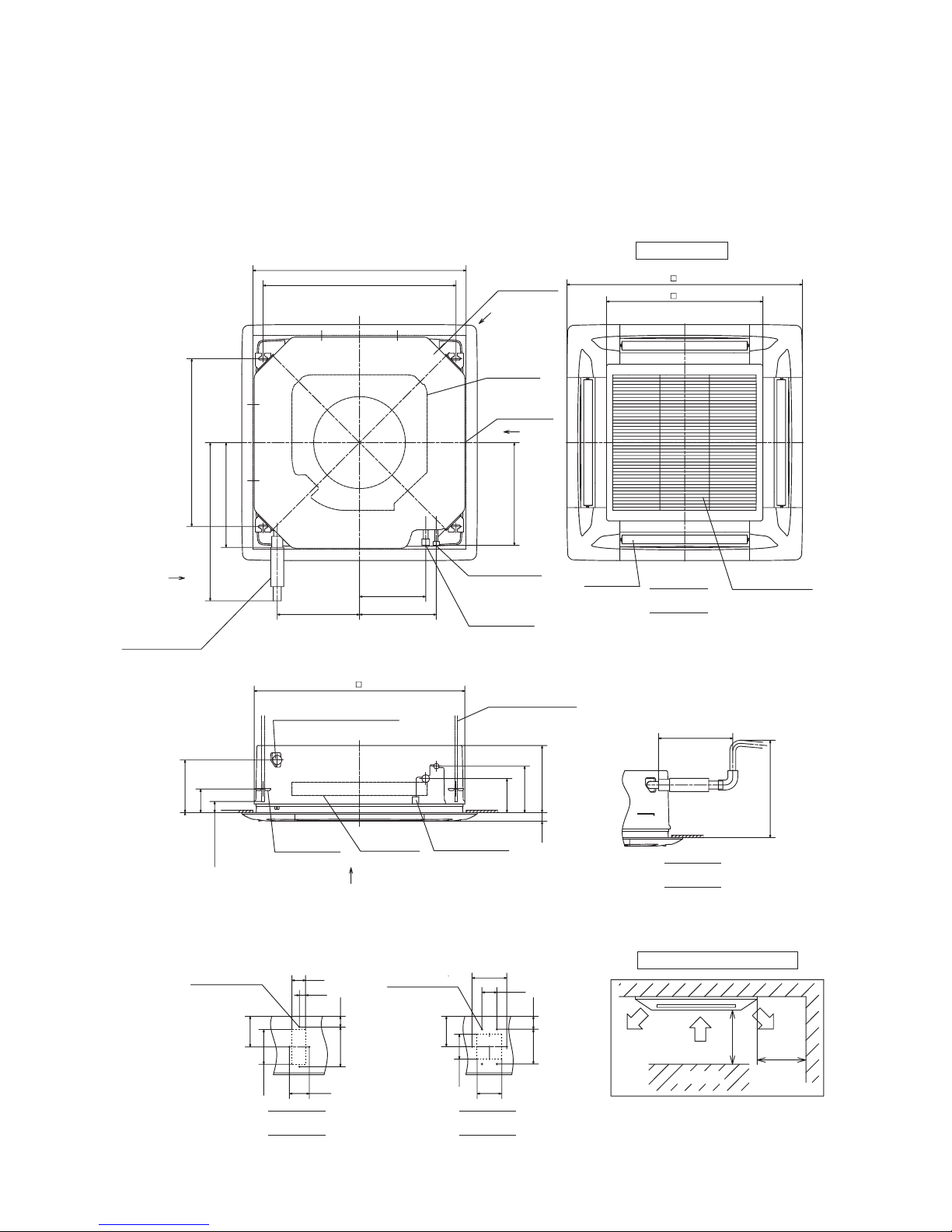
Air supply
Air return grille
VIEW A
VIEW B
VIEW C VIEW D
Decorative Panel
700
or less
(Max. Drain up)
Drain hose piece
(Accessory)
(Installed at site)
Hole for wiring
840
212
95
45
35 270
187
137
332
637
422
420
310
267
950
630
295~325
122
100
25
55
123
140
80 100
160 43
60
140
140 52
ø15.88(5/8")
A
6-ø4
4-ø4
860~890
(Ceiling hole size)
780
(Suspension bolts pitch)
675
(Suspension bolts pitch)
Control box
Outside air
opening for
ducting
Exhaust air
opening for
ducting
Control box
Gas piping
ø9.52(3/8")
Liquid piping
or more
Lug for
suspension bolts
Space for installation and service
If you are mounting units close together,
leave a space of 4000 or greater between unit.
Obstacle
Holes for
tapping screws
Holes for
tapping screws
Holes
Holes
Suspension bolts
B
D
C
Drain
(Connectable with VP25)
1000
or more
2500 or more
Model FDTA301R
unit : mm
1.2.3 Exterior dimensions
(1) Indoor unit
(a) Ceiling recessed type (FDT)
-
10
-
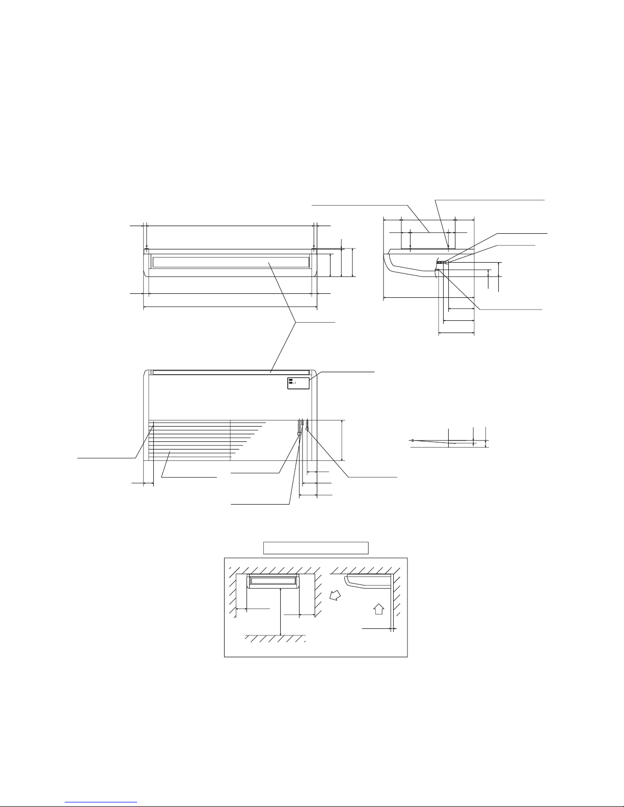
(b) Ceiling suspended type (FDEN)
Model FDENA301R
100
300or more
150
5
75
110
135
308
4040 1240
1320
173
210 5
215
2424
690
195
235
271
53
109
5268
410135
10
53
145
76
1272(Suspension bolts pitch)
290(Suspension bolts pitch)
Air supply
Indication board
ø9.52(3/8")
ø15.88(5/8")
Holes for suspension bolts
(M8 to M10
×
4pcs.Not included)
Liquid piping
Gas piping
Liquid piping
Gas piping
Space for installation and service
or more
or more
or more
Obstacles
Air ireturn grille
Drain hose piece
connection
(1)
Drain hose piece
connection
(1)
Drain hose piece
connection
(1)
(VP20)
(VP20)
(VP20)
Note(1) The slope of drain piping inside the unit is
able to take incline of 10mm.
Unit : mm
If you are mounting units close together,
leave a space of 4500 or greater between unit.
-
11
-
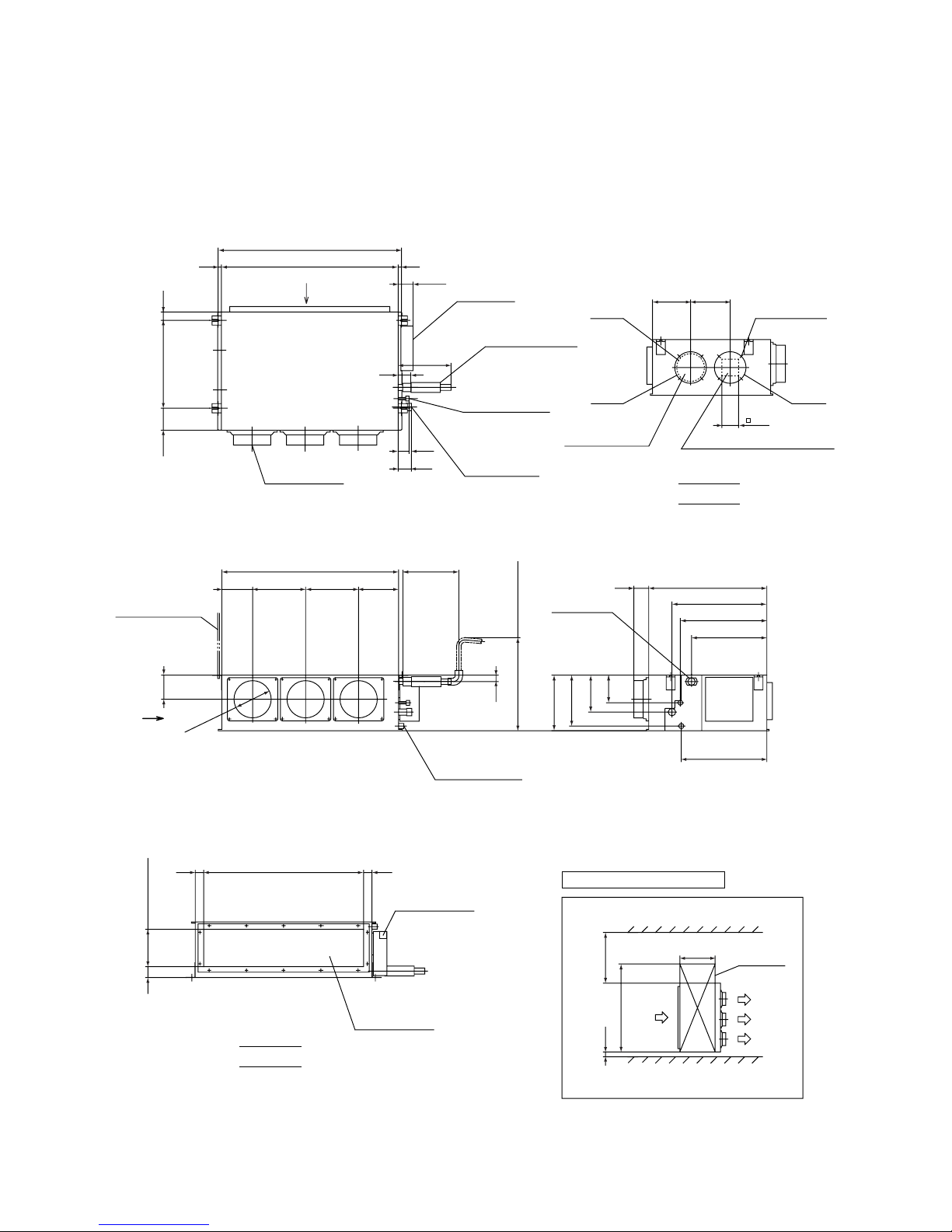
(C) Satellite ducted type (FDUM)
Model FDUMA302R
69
Space for installation and service
620
100
600
1300
45
860
45
59
200
130
165 285
950
285 215
465
510
80
635
405
460
35
149
274
299
199
VIEW B
295~325
(Gravity drainage)
(M10×4pcs.)
600 or less
Suspension bolts
Air return duct
Drain(VP20)
Hole for wiring
Inspection
space
ø200
80.5
18
213205
59
71
950
18
45118
284
986 (Suspension bolts pitch)
Unit : mm
VIEW A
Liquid piping
ø9.52(3/8")
472
(Suspension bolts pitch)
Drain hose piece
(Accessory)
(Installed at site)
Gas piping
ø15.88(5/8")
Fresh air opening
for ducting
(Knock out)
Exhaust air opening for ducting
(Knock out)
A
90
Control box
Air supply duct
B
4-ø4
Holes of
tapping screws
ø149
ø170
ø170
Max.Drain up
Drain
(Connectable
with VP20)
(Duct flange
inner dimeter)
(Duct flange inner dimeter)
-
12
-
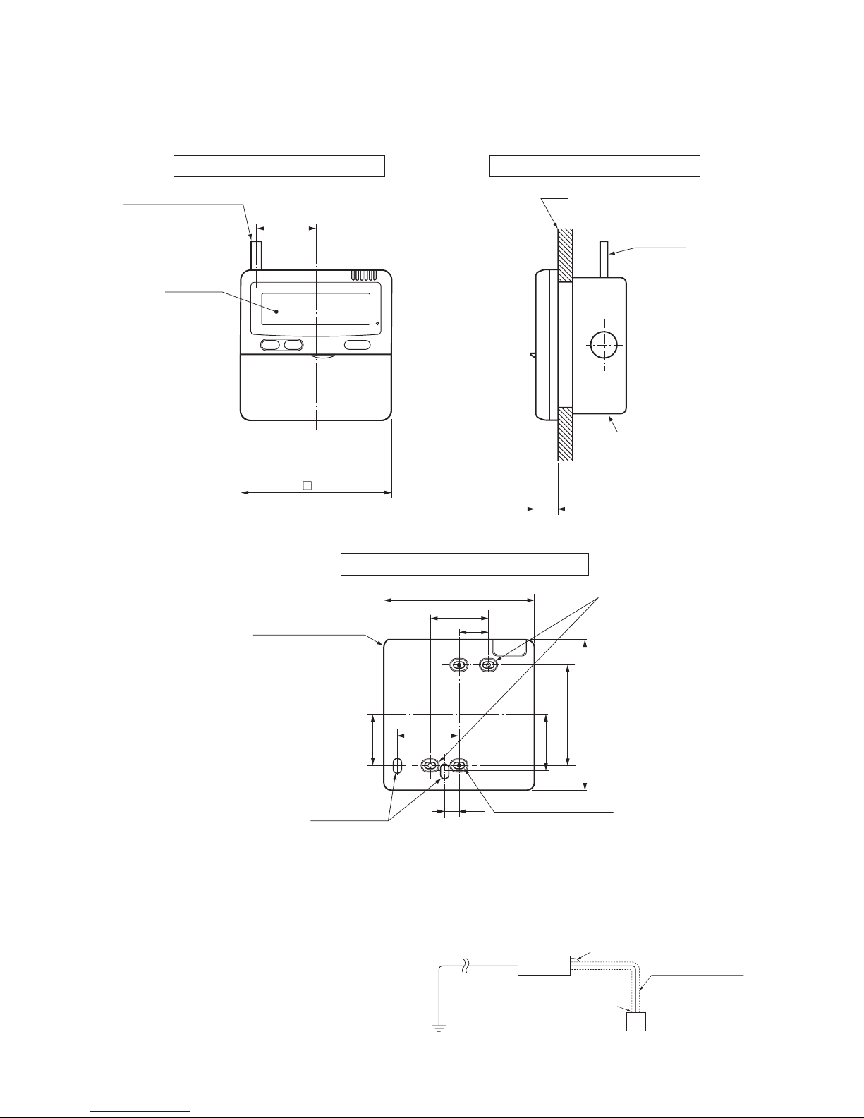
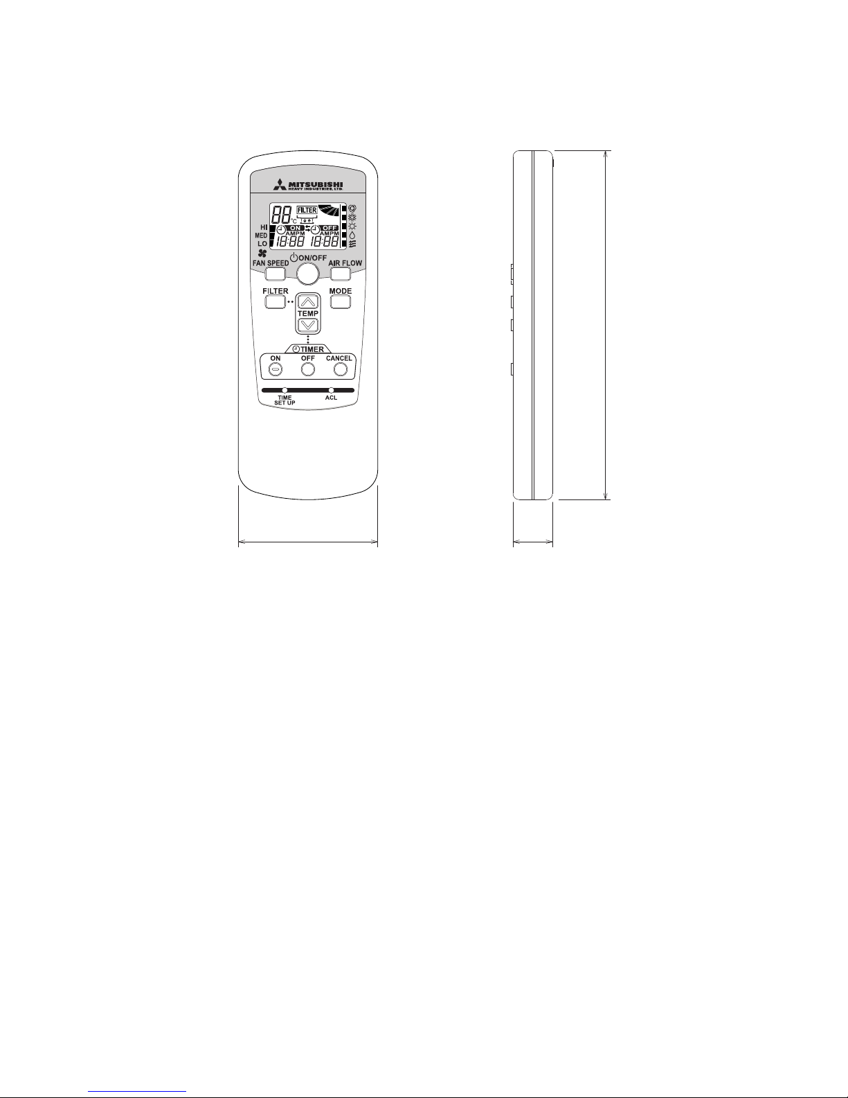
(2) Remote controller (Optional parts)
(a) Wired remote controller
Unit : mm
0.3mm2, 3cores (O.D.ø5.6)
LCD display
120
Wall
Wire
(Recessed)
Electrical box
(Locally Purchased)
19
23
46
11.5
44
Remote controller
outline
120
45
83.5
42
120
Remote controller mounting dimensions
For the passage
after wiring
Attachment hole
12×7 Long hole
9×4.5 Long hole(4 pcs.)
48
Installation with wiring exposed Installation with wiring recessed
Cut off with a knife or the
like thin walled parts intended for screw holes, and then
fix it with screws.
(This side is not grounded)
Earth wiring
Remote control switch
Remote control cord
(Shielded wire)
Precation in Extending the Remote control cord
The cord should be a shielded wire.
● For all types : 0.3mm
2
3 cores
Note: (1) Use cables up to 0.5mm
2
(maximum) for those laid inside the remote control unit casing and connect to a different size
cable at a vicinity point outside the remote control unit, if necessary.
● The shielded wire should be grounded at one side only.
Maximum total extension 600m.
Within 100-200m
…………
Within 300m
…………
Within 400m
…………
Within 600m
…………
0.5 mm
2
0.75 mm
2
1.25 mm
2
2.0 mm
2
3 cores
3 cores
3 cores
3 cores
▼
Indoor unit
-
13
-
(b) Wireless remote controller
60 17
150
-
14
-
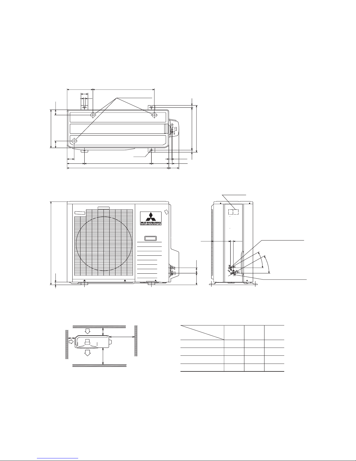
(3) Outdoor unit
Model FDCVA302HENR
Unit: mm
Terminal block
Gas piping ø15.88 (5/8")
Liquid piping ø9.52(3/8")
(Flare connecting)
(Flare connecting)
25.1165.5
30
°
30°
48.5103.3
750
24.1
Holes for drain
2-ø15
25.8
29.8
87.9
880
150580150
61
532
223
60
15
340
61 47.5
19 380 19
418
Required space for maintenance and air flow Minimum allowable space to the obstacles
Unit:mm
Mark
123
L1 Open Open
500
L2 300 250 Open
L3 100 150
100
L4 250 250 250
Installation
type
Notes
(1) It is prohibited to install in a space enclosed with walls
at four sides.
(2) Unit must be secured with anchor bolts.
Anchor bolt should not protrude more than 15 mm above
the surface.
(3) Where strong winds blow,the blow outlet must be
oriented at right angle against the wind direction.
(4) Secure a space of 1 m or more above the unit.
(5) Barrier standing in front of the blow outlet mustbe lower
than the height of unit.
L2
L1
L3
L4
Air inlet
Air outlet
Maintenance
space
( )
Air
inlet
(ø20×3 pcs.)

-
15
-
1.2.4 Inside view
Outdoor unit
Control box
4way valve
High pressure
switch
(63H1)
Low pressure
sensor
(PSL)
Electronic
expansion valve
(EEVH)
Electronic
expansion valve
(EEVC)
Solenoid valve
(SV1)
Compressor
Service valve
(Liquid side)
Service valve
(Gas side)
-
16
-
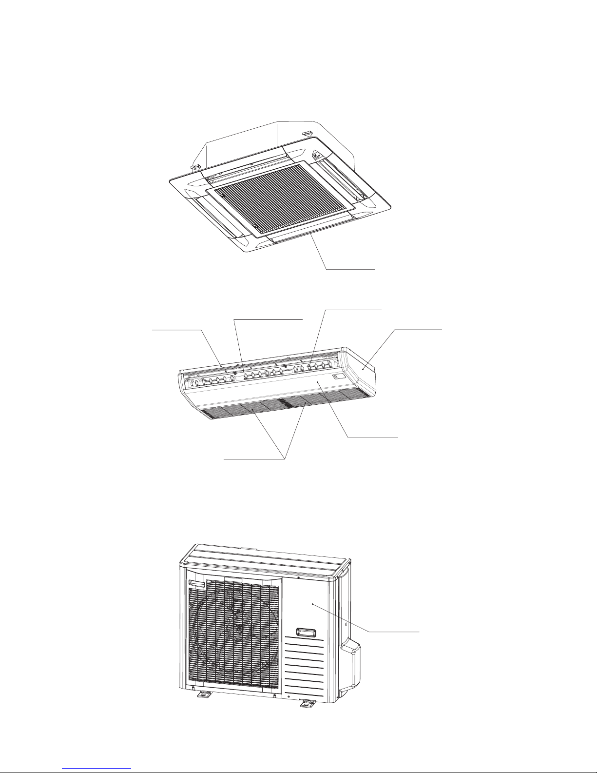
1.2.5 Exterior appearance
(1) Indoor unit
(a) Ceiling recessed type (FDT)
Plaster white
Plaster white
Plaster white
Plaster white
(Front panel)
(Front panel)
(Side panel)
(Vertical louver)
(Horizontal louver)
Light gray
Light gray
(Air return grille)
Plaster white
(b) Ceiling suspended type (FDEN)
(c) Satellite ducted type (FDUM)……Zinc steel plate
(2) Outdoor unit
Stucco white
-
17
-
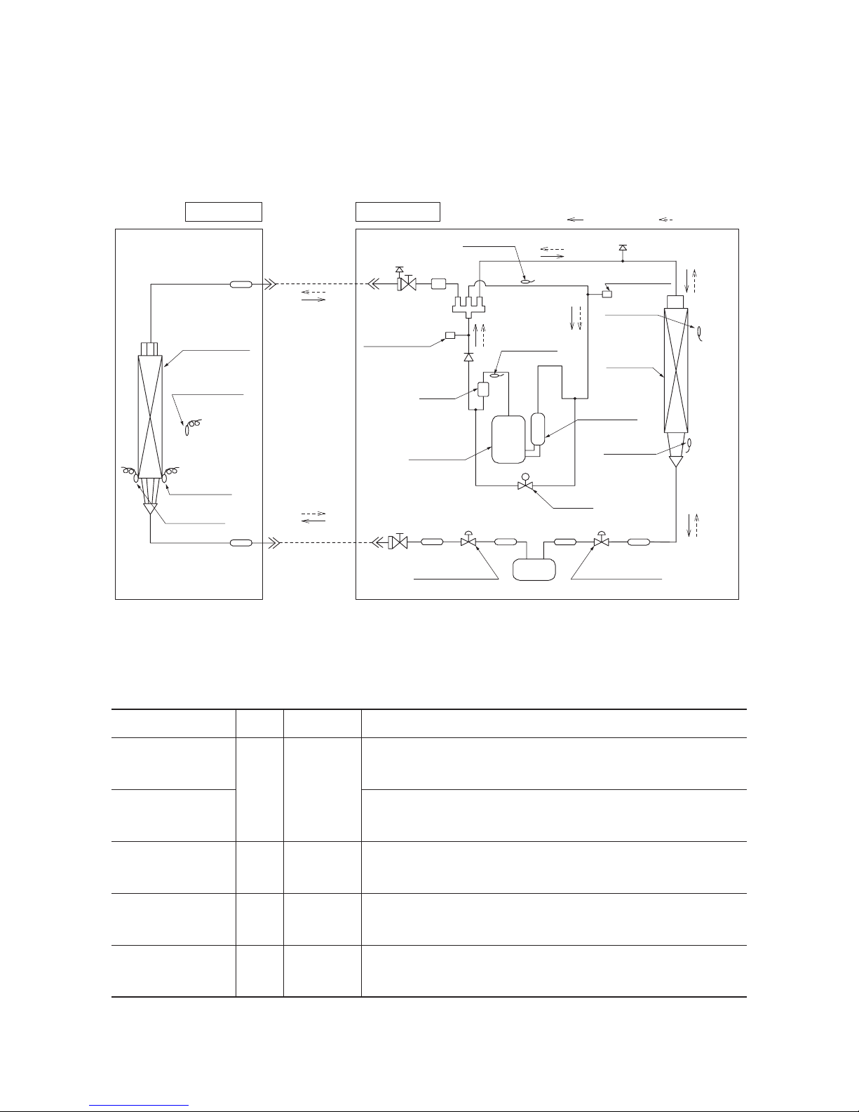
1.2.6 Piping system
Model 302 series
Cooling cycle
Heating cycle
Thermistor
(Th
I
-R2)
Thermistor
(Th
I
-R1)
Thermistor
(Th
O
-D)
Thermistor
(Th
O
-S)
Thermistor
(Th
O
-A)
Service valve
(Flare connecting)
Service valve
(Flare connecting)
High pressure
switch
Low pressure
sensor
(63H1)
(LPT)
(SV1)
Thermistor
(Th
O
-R)
(EEVH)
Thermistor
(Th
I
-A)
Heat exchanger
Heat
exchanger
Solenoid
valve
Strainer
Strainer
Strainer
Strainer
Liquid line
(ø9.52)
Gas line
(ø15.88)
4way valve
Muffler
Muffler
Compressor
Compressor
accumlator
Check joint
Check joint
Check valve
Indoor unit
Outdoor unit
Electronic
expansion valve
Electronic
expansion valve
(EEVC)
Strainer
Strainer
Receiver
Parts name
Mark
Thermistor
(for protection overloading in heating)
Thermistor
(for frost prevention)
Thermistor
(for detecting discharge pipe temp.)
High pressure switch
(for protection)
OFF 63
℃
ON 56
℃
Equipped
unit
Th
I
-R
Th
o
-D
63H1
Indoor unit
Outdoor unit
Outdoor unit
OFF 1.0
℃
ON 10
℃
302 series
OFF 4.15MPa
ON 3.15MPa
Low pressure sensor
(for protection)
LPT
Outdoor unit
OFF 0.227MPa
ON 0.079MPa
OFF 115
℃
ON 85
℃
Preset point of the protective devices
Note(1) A FDEN type strainer only should be used for the indoor unit
-
18
-
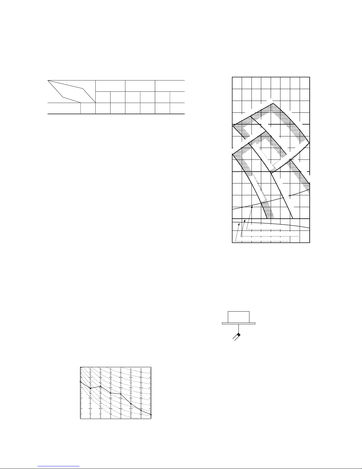
1.2.7 Selection chart
Correct the cooling and heating capacity in accordance with the conditions as follows. The net cooling and heating capacity can be
obtained in the following way.
Net capacity = Capacity shown on specification × Correction factors as follows.
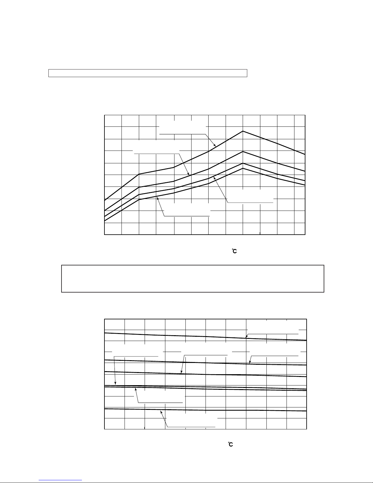
(1) Coefficient of cooling and heating capacity in relation to temperatures
(a) Capacity compensation coeffcient
1) Cooling
0.40
0.50
0.60
0.70
0.80
0.90
1.00
1.10
1.20
1.30
1.40
-
15-10
-
50 51015202530354043
Outdoor air temperature ( DB)
Capacity compensation coeffcient
Indoor air
temperture 24℃W.B
Indoor air
temperture 19
℃
W.B
Indoor air
temperture 12
℃
W.B
Indoor air
temperture 16
℃
W.B
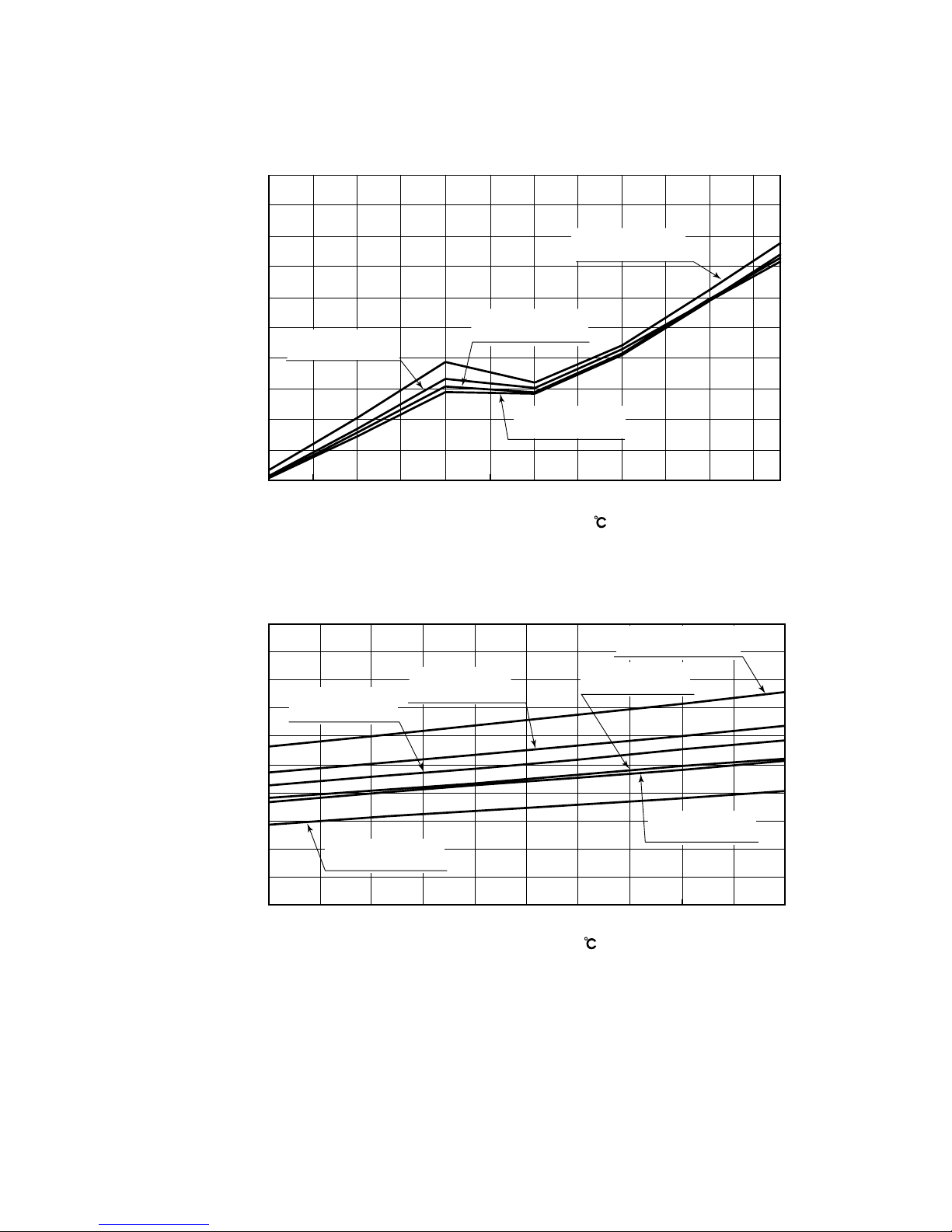
2) Heating
15 16 17 18 19 20 21 22 2423 25
Indoor air temperature ( DB)
Capacity compensation coeffcient
0.50
0.60
0.70
0.80
0.90
1.00
1.10
1.20
1.40
1.30
1.50
Outdoor air
temperture 18.5
℃W.B
Outdoor air
temperture 6
℃W.B
Outdoor air
temperture 10
℃W.B
Outdoor air
temperture 1
℃W.B
Outdoor air
temperture -10
℃W.B
Outdoor air
temperture 0
℃W.B
If a cooling operation is done when the outdoor air temperature is -5˚C or lower, as much as possible, the outdoor unit should be
installed in a condition where it is not going to be influenced by natural wind. If it is hit by the wind, the compressor stop
frequency will be high because of the drop in the low pressure, the capacity will drop even further and it could cause the unit to
break down.
Caution:
-
19
-
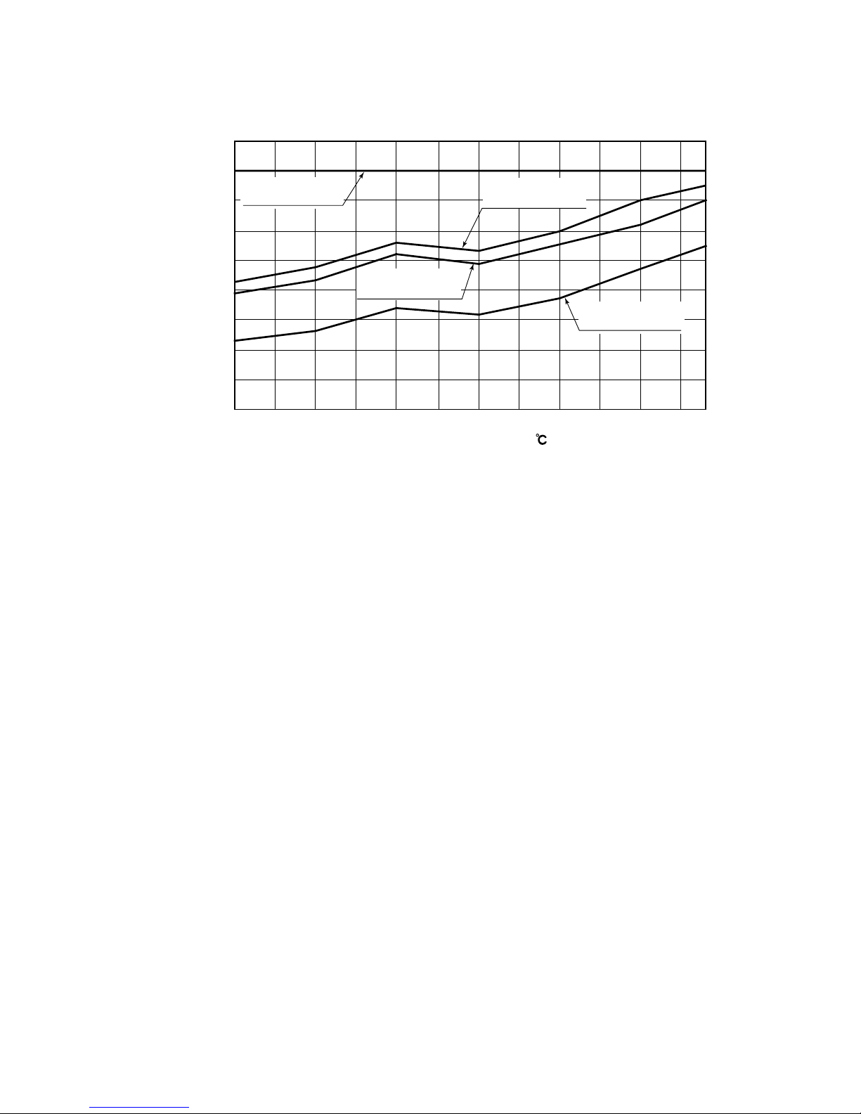
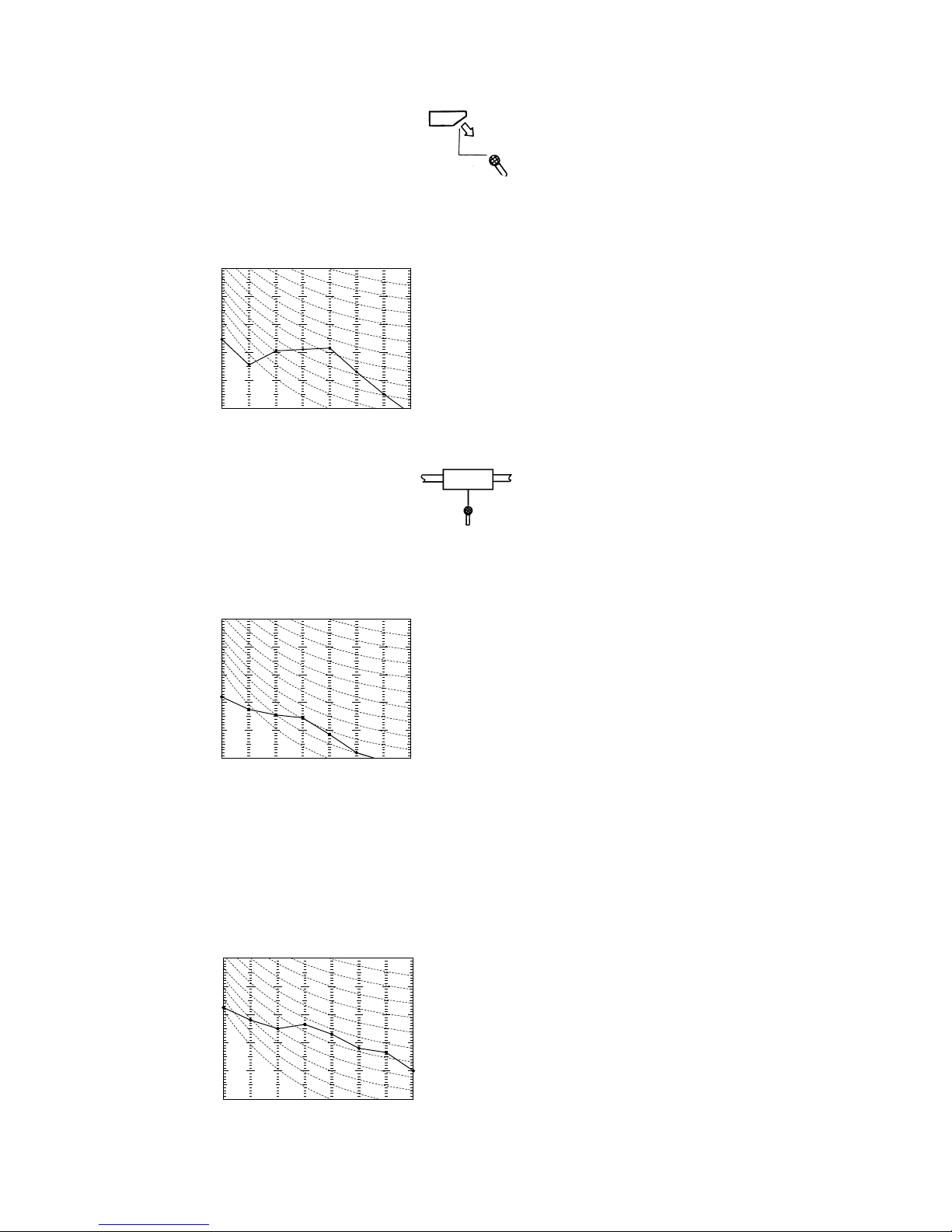
(b) Power consumption correction factor
1) Cooling
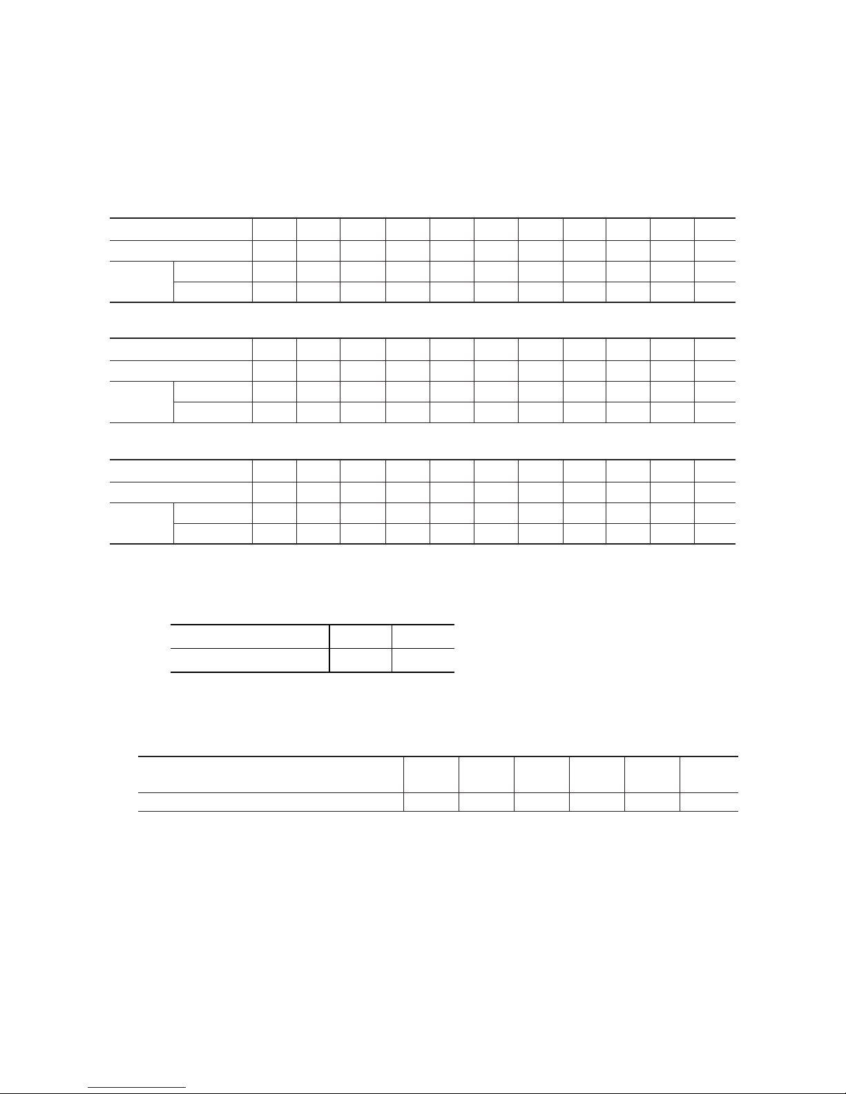
2) Heating
Outdoor air temperature ( DB)
Power consumption correction factor
0.40
0.50
0.60
0.70
0.80
0.90
1.00
1.10
1.20
1.30
1.40
-
15-10
-
50 5 1015202530354043
Indoor air
temperture 24
℃
W.B
Indoor air
temperture 19
℃
W.B
Indoor air
temperture 12
℃
W.B
Indoor air
temperture 16
℃
W.B
Indoor air temperature ( DB)
Power consumption correction factor
0.50
0.60
0.70
0.80
0.90
1.00
1.10
1.20
1.40
1.30
1.50
15 16 18 20 22 2417 19 21 23 25
Outdoor air
temperture 18.5
℃W.B
Outdoor air
temperture 6
℃W.B
Outdoor air
temperture 10
℃W.B
Outdoor air
temperture 1
℃W.B
Outdoor air
temperture -10
℃W.B
Outdoor air
temperture 0
℃W.B
-
20
-
(c) Sensible heat factor
Outdoor air temperature ( DB)
Sensible heat factor
0.60
0.65
0.70
0.75
0.80
0.85
0.90
0.95
1.00
1.05
-
15-10
-
50 5 1015202530354043
Indoor air
temperture 12℃W.B
Indoor air
temperture 24
℃
W.B
Indoor air
temperture 19
℃
W.B
Indoor air
temperture 16
℃
W.B
-
21
-
(3) Correction of cooling and heating capacity in relation to one way length of refrigerant piping
It is necessary to correct the cooling and heating capacity in relation to the one way equivalent piping length between the indoor
and outdoor units.
(4) When the outdoor unit is located at a lower height than the indoor unit in cooling operation and when the outdoor unit is located
at a higher height than the indoor unit in heating operation, the following values should be subtracted from the values in the
above table.
Height difference between the indoor unit and
outdoor unit in the vertical height difference
5m 10m 15m 20m 25m 30m
Adjustment coefficient 0.01 0.02 0.03 0.04 0.05 0.06
(2) Correction of cooling and heating capacity in relation to air flow rate control (fan speed)
Coefficient: 1.00 at High, 0.95 at Low
Note (1) Calculate the equivalent length using the following formula.
However, install the piping so that the equivalent length is within +5 m of the piping distance limit (actual length) for each respective piping system.
● Equivalent length = Actual length + (equivalent length of bends x number of bends in the piping)
Equivalent length for 1 bend
0.15
ø9.52 ø15.88
0.25
Gas pipe diameter (mm)
Bend equivalent length
Equivalent piping length
(1)
(m) 7.5 10 15 20 25 30 35 40 45 50 55
Heating 1 1 1 1 1 0.998 0.998 0.993 0.993 0.988 0.988
ø 15.88 1 0.996
0.989 0.982 0.975 0.968 0.961 0.954 0.947
0.940 0.933
ø 19.05
1.008 1.006 1.003 1 0.997 0.994 0.991 0.988 0.985 0.982 0.979
Cooling
• Outdoor air temperature degree 5˚C or more
Equivalent piping length
(1)
(m) 7.5 10 15 20 25 30 35 40 45 50 55
Heating 1 1 1 1 1 0.998 0.998 0.993 0.993 0.988 0.988
ø 15.88 0.800 0.793
0.779 0.765 0.751 0.738 0.724 0.710 0.696
0.682 0.669
ø 19.05
0.806 0.798 0.786 0.774 0.762 0.750 0.738 0.727 0.715 0.703 0.691
Cooling
• Outdoor air temperature degree -5˚C or more
Equivalent piping length
(1)
(m) 7.5 10 15 20 25 30 35 40 45 50 55
Heating 1 1 1 1 1 0.998 0.998 0.993 0.993 0.988 0.988
ø 15.88 0.600 0.590
0.569 0.549 0.528 0.507 0.487 0.466 0.446
0.425 0.404
ø 19.05
0.605 0.590 0.569 0.548 0.527 0.507 0.486 0.465 0.444 0.424 0.403
Cooling
• Outdoor air temperature degree -15˚C or more
-
22
-
Item
Model
302 servies
Max. one way piping length 50m
Max. vertical height difference Outdoor unit is higher 30m Outdoor unit is lower 15m
Piping length limitations
How to obtain the cooling and heating capacity
Example : The net cooling capacity of the model FDTVA302HEN1R with the air flow “High”, the piping length of 15m, the outdoor unit
located 5m lower than the indoor unit, indoor wet-bulb temperature at 19.0 ˚C and outdoor dry-bulb temperature 35 ˚C is
Net cooling capacity = 7.1 × 1.00 × (0.989 - 0.01) × 1.0 ≒ 7.0 kW
Factor by air
temperatures
FDTVA302HEN1R Air flow
“High”
Length 15m.
Height difference 5 m
Note (1) Values in the table indicate
the one way piping length
between the indoor and
outdoor units.
-
23
-
100
120
80
60
40
20
0
−10
14 17 20 22
Air flow(m3/min)
Lower
limit
Uppe
r
limit
[Standard]3-spot blower internal resistance
Square duct blower internal resistance
High speed・Upper limit
Standard
・
Upper limit
High speed
・
Low limit
High speed
・
High
High speed
・
Medium
High speed
・
Low
Standard
・
Low
Standard
・
Medium
Standard
・
High
Static pressure (Pa)
2-spot blower internal resistance
1.2.9 Noise level
Notes (1) The data are based on the following conditions.
Ambient air temperature: Indoor unit 27˚C DB, 19˚C WB. Outdoor unit 35˚C DB.
Notes (2) The data in the chart are measured in an unechonic room.
Notes (3) The noise levels measured in the field are usually higher than the data because of reflection.
Notes (4) Noise levels for the FDT and FDEN series show the noise level when in the Powerful mode.
(1) Indoor unit
(a) Ceiling recessed type (FDT)
Measured based on JIS B 8616
Mike position as right
1.5m
Mike (center & low points)
Model FDTA301R
Noise level 38 dB (A) at HIGH
35 dB (A) at MEDIUM
33 dB (A) at LOW
N60
40
50
40
50
63
125
250 500 1000 2000 4000 8000
10
20
30
10
20
30
N50
N40
N30
N20
60
60
N10
Souud Pressure Level
(standard 0.0002µ bar)
Mid Octave Band Frequency (Hz)
1.2.8 Characteristics of fan
(1) Satellite ducted type (FDUM)
Model FDUMA302R
Duct specs.
1 spot
closing
Stan
-
dard
Stan
-
dard
Stan
-
dard
High
speed
Standard Square duct
Unit : Pa
External static pressure table
Model
20 30 65 50 85 55 90
FDUMA302R
Air flow
(m
3
/min)
(4)
High
speed
(4)
High
speed
(1)
Notes (1) 1 spot closing: Round duct flange at center is removed and shield with a
special panel (option).
(2) Standard: ø200 duct are installed at all blowout holes.
(3) Square duct: All round ducts are removed and replaced with special
square duct flanges (option).
(4) When using the high speed setting, turn the dip swich SW9-4 on the
indoor PCB to the ON position.
(When setting from the remote controller, select “Hi CEILING 1” )
-
24
-
Model FDENA301R
Noise level 44 dB (A) at HIGH
41 dB (A) at MEDIUM
39 dB (A) at LOW
Souud Pressure Level
(standard 0.0002µ bar)
Mid Octave Band Frequency (Hz)
N30
N40
N20
N50
N60
N70
63 125 250 500 1000 2000 4000 8000
20
30
40
50
60
70
20
30
40
50
60
70
(b) Ceiling suspended type (FDEN)
Measured based on JIS B 8616
Mike position as right
Unit
1 m
1 m
Mike (front & at low point)
(c) Satellite ducted type (FDUM)
Measured based on JIS B 8616
Mike position as right
Model FDUMA302R
Noise level 35 dB (A) at HIGH
32 dB (A) at MEDIUM
29 dB (A) at LOW
(2) Outdoor unit
Measured based on JIS B 8616
Mike position: at highest noise level in position as below
Distance from front side 1m
Height 1m
Model FDCVA302HENR
Noise level 48 dB (A)
1.5 m
Unit
Mike (center & low points)
N30
N40
N20
N50
N60
N70
63 125 250 500 1000 2000 4000 8000
20
30
40
50
60
70
20
30
40
50
60
70
Souud Pressure Level
(standard 0.0002µ bar)
Mid Octave Band Frequency (Hz)
N30
N40
N20
N50
N60
N70
63 125 250 500 1000 2000 4000 8000
20
30
40
50
60
70
20
30
40
50
60
70
Souud Pressure Level
(standard 0.0002µ bar)
Mid Octave Band Frequency (Hz)
-
25
-
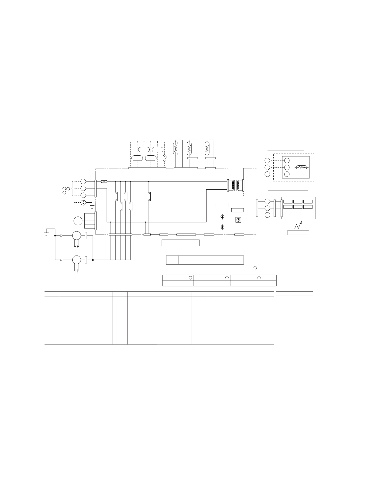
1
3
2/N
X
Y
Z
X
Y
Z
Y/GN
RD
RD
RD
RD
WH
WH
BK
BK
BL
RD
BR
WH
BR
BK
BL
RD
WH
BR
BK
BL
RD
WH
RD
P
BR
OR
RD
WH
BL
OR
OR
WH
BL
Y/GN
CnW1
TB
CnW4
CnW7
CnN4
CnH
X6
X1
X2
X3
X4
CnT
CnJ
CnJ2
CnB
ThC
TB
CnI
CnI2
CnV CnY
CnR
CnR2
CnM3
CnF
CFI
DM
FS
LM1
XR1
XR3
XR2
XR4
XR5
ThI-A
ThI-R1
Option
LM2
LM3
LM4
TrI
To outdoor unit
Power line
Signal line
220/240V 15V
F(3.15A)
F(0.16A)
1
3
5
C
UH
H
M
L
Remote
controller
FMI
CFI
DM
FS
LM1~4
ThI-A
ThI-R1
ThI-R2
ThC
SW2
Fan motor
Capacitor for FMI
Drain motor
Float switch
Louver motor
Thermistor
Thermistor
Thermistor
Thermistor
Remote controller communication address
SW5-3,4
SW9-3
TrI
F
LED1
LED2
XR1
XR2
XR3
XR4
Filter sign
Emergency operation
Transformer
Fuse
Indication lamp(Red)
Indication lamp(Green)
Operation output(DC12V output)
Heating output(DC12V output)
Thermo ON output(DC12V output)
Inspection output(DC12V output)
XR5
X1,2,3,6
X4
TB
CnB~Z
mark
Remote operation input(volt-free contact)
Auxiliary relay(For FM)
Auxiliary relay(For DM)
Terminal block( mark)
Connector
Closed-end connector
Mark Parts nameMark Parts nameMark Parts name
Meaning of marks
Color marks
BK
BL
BR
OR
P
RD
WH
Y
Y/GN
Black
Blue
Brown
Orange
Pink
Red
White
Yellow
Yellow/Green
Mark Color
SW5
SW9
SW2
LED • 2
LED • 1
Power board
Printed circuit
board
1
31
3795
1
1
1
1
1
1
2
3
4
3
5
2
34
23456
2345
2
3
BK
BK
BK
BK
BK
BK
CnN3
CnN1
ThI-R2
FMI
1
3
2/N
Blower fan tap switch
SW9-4
ON
OFF
Fan control, powerful mode
Fan control, mild mode
Function number
A
Function description
B
Setting
C
1 Set SW9-4 provided on the indoor unit PCB to OFF.
Use one of the two methods to set the fan tap.
01
Hi CEILING SET STANDARD
(Mild mode)
BK
BK
RD
RD
CnW2
CnW10
CnW8
CnW5
Select the “STANDARD (Mild mode)” setting for “
C ” in #01 of
“I/U FUNCTION
▲” (indoor unit function) by using remote
controller function setting.
2
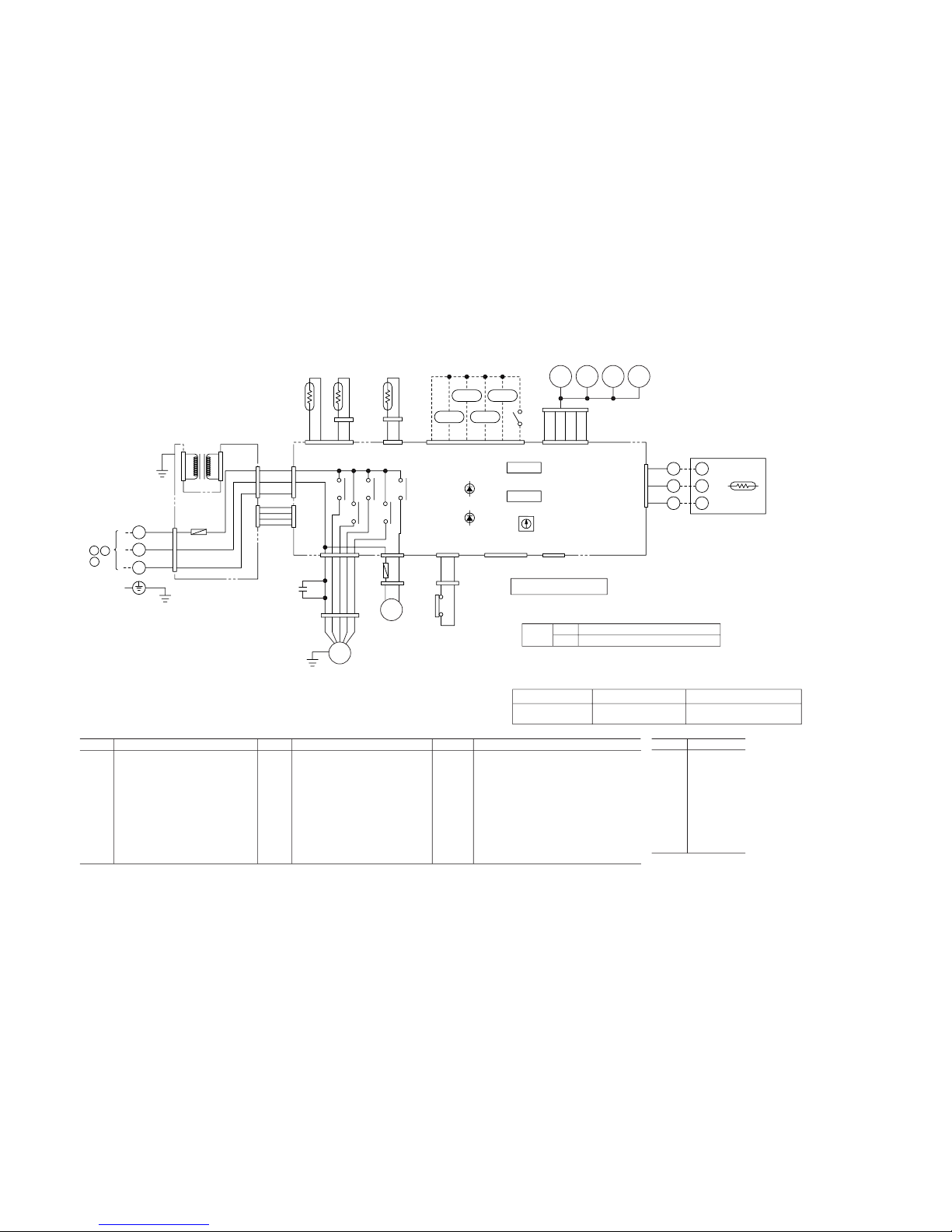
1.3 ELECTRICAL DATA
1.3.1 Electrical wiring
(1) Indoor unit
(a) Ceiling recessed type (FDT)
Model FDTA301R
-
26
-
F (3.15A)
Remote controller
X
CnB CnB2
AMP SW2 SW1
LED3 LED1 LED2
Z
Y
TB
CFI2
CnF2
FMI2
CFI1
FMI1
CnF1
CnR
CnM3
CnI
1
2/N
WH
RD
WH
BR
BK
BL
RD
BK
BK
BK
BK
BK
BK
XR1
XR4
XR5
XR2
XR3
CnT
CnO
CnY
CnV
CnW1
CnW2
TrI
BK RD
BK RD
3
4
1
2
CnN3
CnH
ThI-R1ThI-A
CnN1
ThI-R2
CnN2
1
2
3
11234345621
3
5
1
RD
WH
BK
31
97531
CUHH M L
X6
X1 X3
X2 X4
Option
CnW0
Printed circuit board
TB
220/240V
15V
Y/GN
Y/GN
3
BL
To outdoor unit
Power line
Signal line
1
3
2/N
BL
P
BR
OR
RD
LM
1
2
3
4
5
CnJ1
SW5
SW9
SW2
LED • 2
LED • 1
FMI1,2
CFI1,2
LM
ThI-A
ThI-R1
ThI-R2
ThC
SW2
SW5-3,4
SW9-3
TrI
Fan motor
Capacitor for FMI
Louver motor
Thermistor
Thermistor
Thermistor
Thermistor
Remote controller communication address
Filter sign
Emergency operation
Transformer
F
LED1
LED2
XR1
XR2
XR3
XR4
XR5
X1,2,3,6
TB
CnB~Z
Fuse
Indication lamp(Red)
Indication lamp(Green)
Operation output(DC12V output)
Heating output(DC12V output)
Thermo ON output(DC12V output)
Inspection output(DC12V output)
Remote operation input(volt-free contact)
Auxiliary relay(For FM)
Terminal block( mark)
Connector
mark
LED•1
LED•2
LED•3
SW1
SW2
Closed-end connector
Indication lamp(Green-Operation)
Indication lamp(Yellow-Timer/Check)
7-segement indicator(For check)
Switch(For setting)
Backup switch(Operation/Stop)
Mark Parts nameMark Parts nameMark Parts name
Meaning of marks
Color marks
Wireless specification
BK
BL
BR
OR
P
RD
WH
Y
Y/GN
Black
Blue
Brown
Orange
Pink
Red
White
Yellow
Yellow/Green
Mark Color
Y/GN
Blower fan tap switch
SW9-4
ON
OFF
Fan control, powerful mode
Fan control, mild mode
A
B
C
Function number Function description Setting
1 Set SW9-4 provided on the indoor unit PCB to OFF.
01
Hi CEILING SET STANDARD
(Mild mode)
Wired specification
Remote
controller
ThC
XX
Z
Y
Z
Y
TB
RD
WH
BK
C
Use one of the two methods to set the fan tap.
Select the “STANDARD (Mild mode)” setting for “ ” in #01 of
“I/U FUNCTION
▲” (indoor unit function) by using remote controller function setting.
2
(b) Ceiling suspended type (FDEN)
Model FDENA301R
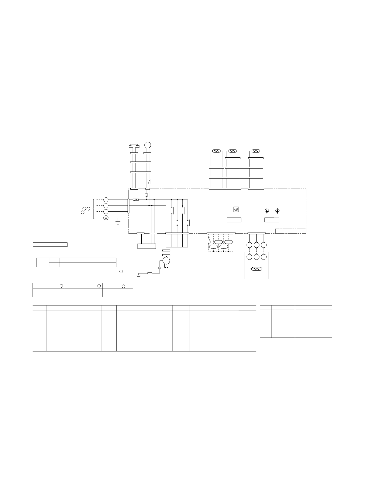
-
27
-
(c) Satellite ducted type (FDUM)
Model FDUMA302R
1
2/N
3
C
To outdoor unit
Power wires
Signal wire
SW9
SW5
CnI2
CnR2
CnRI1
CnRI
CnI
CnR
CnH
CnH2
CnN3
CnNZ
CnN1
CnN6
CnN5
CnW0
CnW2 CnW1
SW2
LED
•
1
LED
•
2
RD
WH
BL
TB
1
2/N
3
Y/GN
Y/GN
Y/GN
F(3.15A)
F(0.16A)
FS
DM
X4
X6 X2
X1 X3
WHWH
BR
BR
BK
BK
BK
BK
BK
BK
RD/Y
BL/Y
BK
Y
OR
RD
RD
BK
BK
BR/Y
WH
RD
RDRD
RDRD
RD
RD
RD
RD
RD
RD
RD
RD
RD RD
RD
RD
RD
ThI-A ThI-R1 ThI-R2
XR3 XR1
XR5
XR2XR4
CnT
CnM3
CnF3
CnF3
CnG
CnS
Option
CUH H M L
FMI1
CFI1
TrI
15V
220/
240V
Printed circuid board
FMI1
CFI1
DM
FS
ThI-A
ThI-R1
ThI-R2
ThC
Fan motor
Capacitor for FMI
Drain motor
Float switch
Thermistor
Thermistor
Thermistor
Thermistor
SW5-3,4
SW9-3
TrI
F
LED
•
1
LED
•
2
XR1
Filter sign
SW2
Remote control communications address
Emerqency operation
Transformer
Fuse
Indication lamp(Red:inspection)
Indication lamp(Green:normal operation)
Operation output(DC12V output)
XR2
XR3
XR4
XR5
X1,2,3,6
X4
TB
CnA~Z
mark
Heating output(DC12V output)
Thermo ON output(DC12V output)
Inspection output(DC12V output)
Remote operation input(volt-free contact)
Auxiliary relay(For FM)
Auxiliary relay(For DM)
Terminal block( mark)
Connector(
□
mark)
Closed-end connector
Mark
Mark
Mark Parts name Parts name Parts name
Meaning of marks
Color marks
BK
BL
BL/Y
BR
BR/Y
Black
Blue
Blue/Yellow
Brown
Brown/Yellow
OR
RD
RD/Y
WH
Y
Y/GN
Orange
Red
Red/Yellow
White
Yellow
Yellow/Green
Mark Color
Mark Color
XYZ
XYZ
RD
RD
WH
WH
BK
BK
CnB
ThC
TB
Remote
controller
1
21 31
3421
65
432 1
123
1
3
579
3
5
Blower fan tap switch
SW9-4
ON
OFF
Fan control, high speed (High ceiling)
Fan control, standard
A
B
C
Function number Function description
Setting
Use one of the two methods to set the fan tap.
1Set SW9-4 provided on the indoor unit PCB to ON.
01
Hi CEILING SET
Hi CEILING 1
2Select the “Hi CEILING 1 (High-speed tap)
”
setting for “ ”
in #01 of
“
I/U FUNCTION
▲”
(Indoor unit fuction) by using
remote controller function setting.
-
28
-
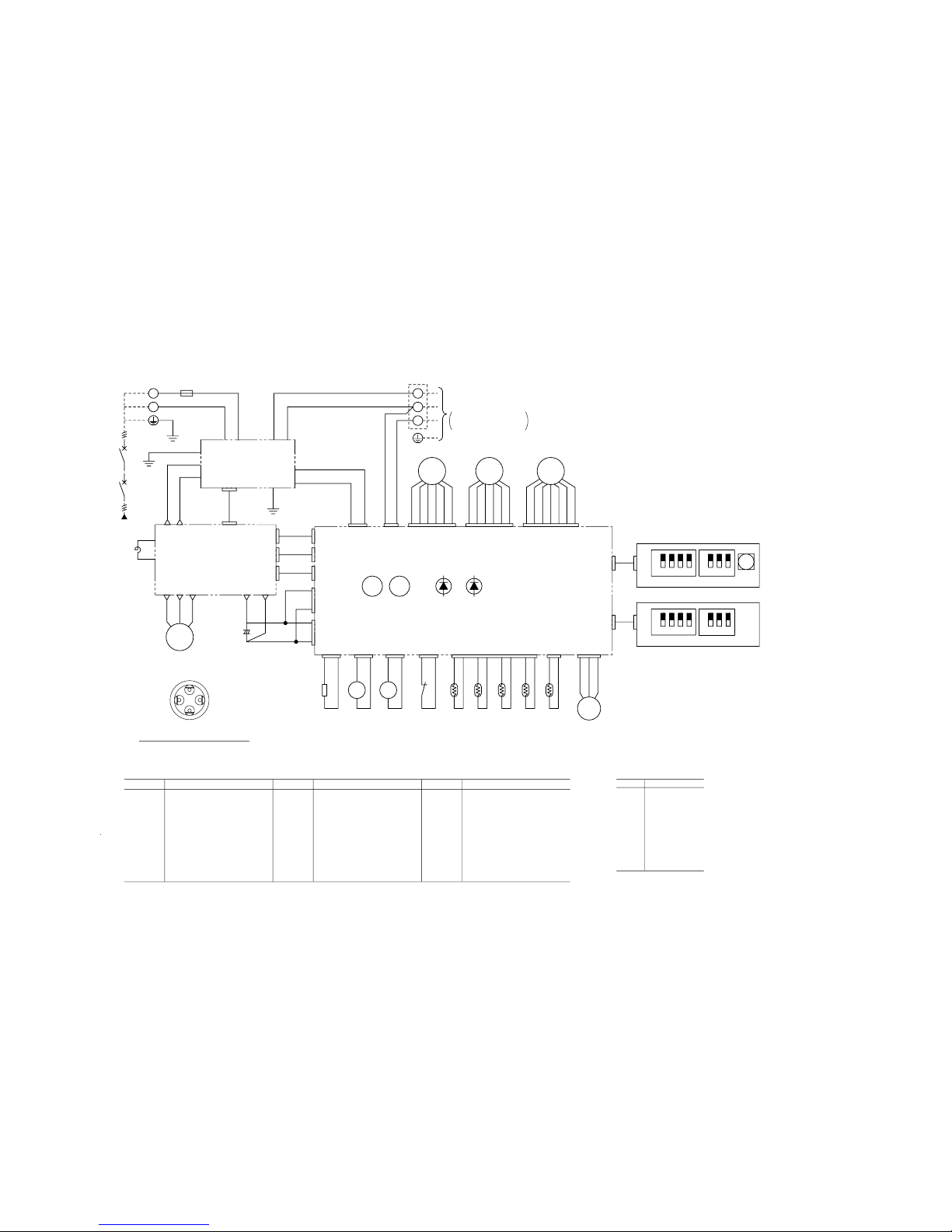
(2) Outdoor unit
Model FDCVA302HENR
RD
WH
RD
N
L1
CM
BL
BL
RD
WH
CNG1
CH
CNR
BR
BR
20S
BK
CNS
BK
52X1
PWB1
52X3
CNW
RD
WH
CNW2
GR
BR
OR
CNFANCNEEV1CNEEV2
THo-D
CNTH
63H1
CNH
BK
BK
THo-R1
BK
BK
BK
BK
LED2LED1
132
SW5
BK
BK
CNQ1
CNQ1
CNQ2
4
ON
THo-ATHo-S THo-IP
RD
RD
Y
CNIP
BK
Y
BK
LPT
CNPS
WH
BK
RD
SW9
3
SW8
12
ON
132
SW3
CNQ2
4
ON
3
SW7
12
ON
BL
756
Y
WH
243 1
BR
BL
OR
RD
45623
OR
Y
WH
BR
BL
189
RD
P
GR
65 14
WH
Y
RD
BK
FMO1
Yellow/Green
Color
Position of compressor terminals
WH White
GR
Y
Y/GN
Gray
P Pink
Yellow
Mark
Color marks
BR
OR
RD
BK
BL
Red
Orange
Brown
Blue
Black
Auxillary relay (for 20S)
Expansion valve for cooling
Solenoid valve for 4 way valve
Auxillary relay (for CH)
Parts name
Crankcase heater
SM1
20S
52X3
CH
52X1
Fan motor
Compressor motor
FMO1
Mark
Meaning of marks
CM
High pressure switch
Thermistor (H.X. temp.)
Thermistor (discharge temp.)
Low pressure sensor
Thermistor (suction temp.)
Thermistor (Outdoor air temp.)
Solnoid valve
Thermistor (IPM)Tho-IP
SV1
LPT
Tho-R1
Tho-D
Tho-S
Tho-A
Expansion valve for heating
Parts name
SM2
63H1
Mark
Local setting switch
Indication lamp (GREEN)
Indication lamp (RED)
Reactor
Pump down switch
Diode module
L1
LED1
DM
LED2
SW9
SW3,5,7,8
Terminal block
Fuse
ConnectorCnA~Z
TB
F
Parts nameMark
GR
CNI1
BK
Y
BL
CNI2
CNG2
CNO1
CNO2
PWB2 Inverter
PWB3 N/F
RD
BL
RD
BL
F(20A)
CNA1
CNA2
Y/GN
Y/GN
Y/GN
RD
WH
TB
3
TB
1
2
S.M2 S.M1
Power source
1Phase 220-240V
To indoor unit
Power wires
12
Signal wire 3
SV1
BK
CNS
BK
L1
C1
CNI3
BL
CNI4
T27T26WVU
T25
T24
T21 T22
T13
T11
T10
T9T8T1T2
T4
T5
T6
RD
BK
U(RD)
V(WH)
W(BL)
DON'T
CONNECT
-
29
-
1.4 OUTLINE OF OPERATION CONTROL BY MICROCOMPUTER
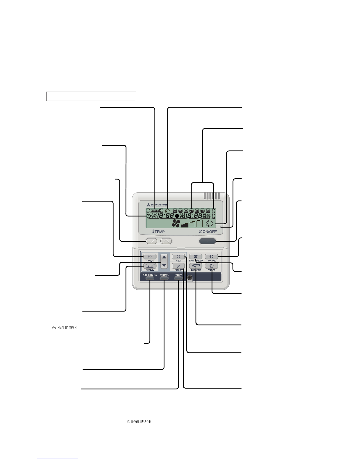
(1) Remote controller
(a) Wired remote controller
The figure below shows the remote controller with the cover opened. Note that all the items that may be displayed in the
liquid crystal display area are shown in the figure for the sake of explanation.
Characters displayed with dots in the liquid crystal display area are abbreviated.
Pull the cover downward to open it.
*If you press any of the switches above and " " is display, the switch has no function.
But it does not mean a failure.
Weekly timer display
Displays the settings of
the weekly timer.
Vent Indicator
Indicates operation in the
Ventilation mode.
ON/OFF switch
This switch is used to operate and
stop the air conditioning system.
Press the switch once to operate
the system and press it once again to
stop the system.
MODE switch
This switch is used to switch between
operation modes.
Operation setting display area
Displays setting temperature,
airflow volume, operation mode and
operation message.
Operation/Check indicator light
During operation: Lit in green
In case of error: Flashing in red
FAN SPEED switch
This switch is used to set the
airflow volume.
SET switch
This switch is used to apply the timer
operation setting.
This switch is also used to make silent
mode operation settings.
RESET switch
The switch which returns to
a previous step.
Central control display
Displayed when the air conditioning
system is controlled by the option controller.
Timer operation display
Displays the settings related to
timer operation.
AIR CON No. (Air conditioning system No.) switch
Displays the number of the connected
air conditioning system.
CHECK switch
This switch is used at servicing.
TEST switch
This switch is used during test operation.
Temperature setting switches
These switches are used to set
the temperature of the room.
VENT switch
Switch that operates the
connected ventilator.
Timer setting switches
These switches are used to set
the timer mode and time.
TIMER switch
This switch is used to select
a timer mode.
GRILL switch
This switch has no function.
When this switch is pressed,
(Invalid Operation)
is displayed, but it does not mean a failure.
LOUVER switch
This switch is used to operate/stop
the swing louver.
27
˚
C

-
30
-
(b) Wireless remote controller
Indication section
FAN SPEED indicator
Indicates the selected blow rate.
ON-TIMER indicator
Indicated when ON-TIMER is set.
ROOM TEMP. indicator
Indicates set temperature.
AIR FLOW indicator
Indicates the condition of swing flap.
ON-TIMER setting time indicator
Indicates the ON-TIMER setting time.
Indicates nothing when ON-TIMER is not set.
OFF-TIMER indicator
Indicated when OFF-TIMER set.
OFF-TIMER setting time indicator
Indicates OFF-TIMER setting time. Indicates
the current time when the OFF-TIMER is not set.
OPERATION MODE indicator
Indicates selected operation with lamp.
FILTER indicator
Indicates for 2 seconds when FILTER button
is pressed.
Operation section
FAN SPEED button
Every time when the button is pressed,
the mode is sequentially changed in
order.
HILOMED
OPERATION MODE select button
The operation mode on the side of the
indicator is the currently selected operation mode. It will switch in order.
ON-TIMER button
This button selects ON-TIMER operation.
OFF-TIMER button
This button selects OFF-TIMER operation.
TIME SET UP switch
This switch for setting the time.
ROOM TEMP. button
Press either the or
but ton to set the room temperature.
ACL switch
This is a switch to reset the microcomputer
.
TIMER CANCEL button
This button cancels the timer settings.
FILTER button
Used to reset (turn off) the filter sign.
Press the button only after completing
the filter cleaning.
Signal sender
Signal are sent to the air conditioner
from here.
AIR FLOW button
Used to start or stop the swing flap.
ON/OFF button
When the button is pressed, the air conditioner is started, and when the button is
pressed once again, it is stopped.
(FAN)
(AUTO) (COOL)
(DRY)
(HEAT)

-
31
-
Cooling Fan Heating Dry
Control part
Compressor
4-way valve
Outdoor fan
Indoor fan
/
/
Louver motor
/
Condensate motor
(5min. ON) (5min. ON)
(5min. ON)
(5min. ON)
Note (1) :ON
:OFF
/ × :According to control other than temperature control.
Thermostat
ON
(c) Control parts operation during cooling and heating
Function
–
Temperature difference between thermostat set temp.
and return air temp. (Detected by ThI-A)
Temperature difference between thermostat set
temp. and return air temp. (Detected by Th
I
-A)
Heating operation
OFF
+1
-1
Set temp.by thermostat
Cooling operation
OFF
+1
-1
Set temp.by thermostat
ON
(2) Operation control function by the indoor unit controller
(a) Room temperature control (Differential of thermostat)
(b) Automatic operation
If the Auto mode is selected on the remote control device, the selection of cooling or heating can be made automatically
depending on the room temperature (and the temperature of indoor heat exchanger). (When the switching between the
cooling and the heating is made within 3 minutes, the compressor will not operate for 3 minutes.) This will make much easier
the switching of cooling/heating at the change of season and can be adapted to the unmanned operation at bank cash dis-
penser.
Notes (1) During the automatic switching of cooling/heating the room
temperature is controlled based on the setting of room temperature.
Notes (2) If the temperature of indoor heat exchanger rises beyond 59˚C during
the heating operation, it is switched automatically to the cooling
operation. For an hour after this switching, the heating operation is
suspended regardless of the temperature as shown at left.
Heating operation
Cooling operation
Setting room temp.
Room temp. (detected at Th
I
-A) [deg]
Ready for
heating
Suspended heating operation
Indoor heat exchanger temperature (˚C)
59
56
Thermostat
OFF
Thermostat
ON
Thermostat
OFF
Hot start
(Defrost)
Thermostat
ON
Thermostat
OFF

-
32
-
(d) Dehumidifying operation (“THERMAL DRY”)
The compressor, the indoor fan motor and the outdoor fan
motor are operated intermittently under thermistor (Th
I-A)
control according to the appropriate operation block, to pro-
vide cooling operation for the dehumidifying.
Notes (1) Blocks A and B: Normal cooling operation for 16 minutes after operation starts, then when the set temperature is reached,
the thermostat stops. 16 minutes later, it switches to normal operation.
Blocks C and D: The operation mode shown in the table above is performed for 8 minutes. After 8
minutes, it switches to normal operation.
Notes (2) Under normal operation, the temperature is checked every 8 minutes after normal operation starts to determine which block is operating,
then the operation mode is decided.
Operation block
DCBA
Set temp. by thermostat
Pattern of operation
Operation
block
Thermal drying starting
(for 8 or 16 minutes after operation started)
A
(16 minutes)
• The air flow is set at 1 speed lower than the set air flow.
(8 minutes)
Continuous cooling operation (FMI:Lo)
B
(8 minutes)
CM, FM0
FMI
C
(8 minutes)
CM, FM0
FMI
(8 minutes)
CM, FM0
FMI
D
(8 minutes) All stoppage
(e) Timer Operation
1) Simple Timer
This sets the amount of time from the current time that the air conditioner goes OFF.
The off time can be selected in 10 steps, from “Off 1 hour from now” to “Off 10 hours from now.” After the simple timer
is set, the number of hours until the air conditioning goes off is displayed in one hour units from the current time.
2) Time Off Timer
The time the air conditioner goes OFF can be set in 10-minute increments.
3) Time On Timer
The time the air conditioner goes ON can be set in 10-minute increments. The set temperature can also be set at the same
time.
CM, FMO: ON FMI : ON
Normal thermal dry operation
(after completion of thermal drying)
Low
-2
+3
High
Normal cooling operation

-
33
-
4) Weekly timer
Each day, it is possible to set this timer's operation up to 4 times (ON time, or OFF timer).
5) Possible joint use timer operation setting combinations
Simple timer
Time OFF timer
Time ON timer
Weekly timer
Simple timer
Time OFF timer
Time ON timer
Weekly timer
(f) Hot start (Cold draft prevention during heating)
When heating operation starts, when the thermostat is reset, during a defrosting operation or when resetting a heating opera-
tion, in order to prevent a cold draft, the indoor heat exchanger (sensed by ThI-R1 and R2) control the indoor fan.
Heating start thermostat judgment
Normal state, set air flow
Indoor heat exchanger (˚C) Indoor heat exchanger (˚C)
25 35
Lo
Fan
OFF
35
Fan
Lo
Set air flow
Indoor heat exchanger (˚C)
20
30
Fan
OFF
Set air flow
Indoor heat exchanger (˚C)
40
45
Fan
Lo
(1)
Set air flow
Set air flow
Heat exchanger temperature 35˚C or above, or 7 minutes passesHeat exchanger temperature 35˚C or above, or 7 minutes passes
Compressor ON Defrosting ends
Thermostat ONThermostat OFF
Defrosting startsCompressor OFF
Notes (1) If J2 starts, it changes from OFF to Lo for 5 minutes.
Notes (2) During Hot Start (the compressor is operating and the indoor fan is not operating at the set air flow), Heating preparation is displayed.
(g) FM control with the heating thermostat turned off (For cold draft prevention)
In order to prevent a cold draft while the heating thermostat is turned off, the indoor blower is controlled in response to the
temperature of the indoor heat exchanger as illustrated below. It should be noted that if jumer wire J2 (SW7-2) on the indoor
PCB is turned off, the indoor blower will stop so far as the temperature of the indoor heat exchanger is lower than 40°C. It
will be turned to the Lo operation 5 minutes later.
Note (1) After the thermostat is reset, it returns to the hot start
control.
(Setting air flow)
Indoor heat exchanger temperature (˚C)
40 45
Lo
Note (1) : Possible, : Impossible

-
34
-
(h) Room temperature sensing temperature compensation during heating
In the standard specifications, the temperature set on the thermostat is used to turn the compressor on and off, but in cases
where the warm air easily escapes to the ceiling and the thermostat ends up turning off too soon, Jumper wire J4 (SW7-4) on
the indoor PCB can be disconnected. When this is done, the compressor can be turned ON and OFF at the set temperature +3
degrees, and the feeling that the room is heated can be improved. However, the upper limit for the set temperature is 30°C.
(i) Filter sign
If operating time (the length of time the ON/OFF switch is ON) totals 180 hours
(1)
, “FILTER CLEANING” is displayed on
the remote control unit. (This is displayed whether the system is running or not, when the unit is broken down, and when
there is central control.)
Notes (1) The following controls are enabled by the combination of the ON/OFF settings of 2 switches on the indoor unit PCB, SW5-3 and SW5-4.
(They are switched OFF when the unit is shipped from the factory. The setting time is 180 hours.)
Operation
Room temperature (deg)
—
1
+ 1
Stop
Standard
Compressor
Operation
Set temperatureSet temperature
Room temperature (deg)
+ 4+2
Stop
If J4 (SW7-4) is disconnected
(if it is turned ON),
Compressor
SW5-3 OFF
SW5-4 OFF
SW5-3 OFF
SW5-4 ON
SW5-3 ON
SW5-4 OFF
SW5-3 ON
SW5-4 ON
Setting time: 180 hrs. (when shipped from factory)
Setting time: 600 hrs. (Display)
Setting time: 1000 hrs. (Display)
Setting time: 1000 hrs. (Unit stop)
FunctionSwitch
Notes (2) When SW5-3, SW5-4 is switched ON, the message “FILTER CLEANING” is displayed after the setting time has passed, then the unit stops after
another 24 hours have passed (including stop time).
(j) Auto swing control (Except the FDUR model)
1) Louver Control
a) While the air conditioner is operating, press the “LOUVER” switch.
“AU TO
” is displayed for 3 seconds and the swing louvers move up and down continuously.
b) When fixing the position of the swing louvers, press the “LOUVER” switch once while the swing louvers are moving. 4
stop positions are displayed in sequence at 1-second intervals.
When the display comes to the position where you would like to stop the louvers, press the “LOUVER” switch once
more. The display will stop the message (ex. “STOP
”) will be displayed for 3 seconds, then the swing louvers will
stop.
c) Louver operation when the louver 4-position controller’s power goes On
When the power is turned ON, the louvers automatically swing 1 time automatically (without remote control operation).
This is done so that the microcomputer can confirm the louver’s position and input the louver motor’s (LM) position to
the microcomputer.
Note (1) When the “LOUVER” switch is turned ON, the louver position LCD display displays the swing operation for 10 seconds.
Then “AUTO
” is displayed for 3 seconds.
2) Auto louver horizontal set during heating
During display of “
” (Heating Preparation) (during hot start and heating thermostat OFF), the louvers are in the
horizontal position regardless of the operation of the auto swing switch (auto swing and louver stop). (In order to prevent
cold drafts.) Also, the louver position display LCD continues the previous display from before this control started.
If the “
” (Heating Preparation) display goes off, the LCD display also returns to the original display.
3) Louver free stop control
Setting an open circuit with jumper wire J5 (SW8-1), used for setting louver free stop, causes the louver motor to stop if
there is a stop signal from the remote control unit and saves the position of the louver in memory. Then if there is an auto
swing signal from the remote control unit, auto swing control starts from the previous stop position.

-
35
-
(k) Condensate pump motor (DM) Control [FDT and FDUM models only]
(a) Drain motor is started no sooner than the compressor is turned ON during cooling or dehumidifying operation. The drain
motor continues to operate for 5 minutes after the stop of unit operation, stop with the error stop, thermostat stop and at
switching from cooling or dehumidifying operation to blowing or heating operation. When there is any unit subjected to oil
return control, the drain motor is operated for 5 minutes at such occasion.
(b) Overflow detection is performed by the float switch at all times regardless of the operating mode. If the float switch
circuit is detected to be open continuously for 3 seconds (or when the float switch is disconnected or a wire is broken), an
abnormal stop (E9) is performed and the condensate pump motor runs until the float switch recovers.
(l) Air flow mode control
Air flow mode control can be changed using DIP switch SW9-4 on the indoor PCB.
Abnormal stop
63
Indoor heat exchanger temperature(˚C)
56
Heating operation possible
Cooling operation
10
Indoor heat exchanger temperature (˚C)
1.0
Fan operation
SW9-4 OFF
(Mild Mode Control)
SW9-4 ON
(Powerful mode Control)
Air flow mode
Item
DIP SW
FDT, FDEN models
Hi, Me, Lo UHi, Hi, Me
(m) Compressor inching prevention control
1) 3-minute timer
If the compressor stops due to operation of the thermostat, the Run switch on the remote controller or some trouble, it is not
restarted after 3 minutes. However, when the power is turned ON, the 3-minute timer becomes inactive.
2) 3-minute forced operation timer
a) For 3 minutes after the compressor goes ON, it does not stop. However, it will stop if the Run/Stop button is pressed
and through a change in the operation mode, it sill stop immediately when the thermostat goes OFF.
b) During 3-minute forced operation timer control in heating operation, if the thermostat goes OFF, the louver position
is set in the horizontal position.
Note (1) The compressor stops when protection control starts.
(n) Heating overload porotection
If an overload condition is sensed continuously for 2 seconds by the indoor heat exchanger temperature during heating
(sensed by Thi-R1 or R2), the compressor is stopped. After a 3-minute delay, the compressor is restarted. If the overload is
sensed 5 times within 60 minutes of the first time it was detected, an abnormal stop is performed (E8). Also, if the overload
state is sensed continuously for 6 minutes, it results in an abnormal stop.
(o) Frost prevention during cooling, dehumidification
In order to prevent frost during cooling and dehumidification, 3 minutes after compressor operation starts, if the indoor heat
exchanger temperature (sensed by Thi-R1 or R2) is 3.5˚C or lower for 30 seconds, the compressor’s speed is lowered. 30
seconds later, if the indoor heat exchanger temperature is 3.5˚C or lower, the speed is reduced still more. If the temperature
becomes lower than 3.5˚C continuously, this control is terminated. Furthermore, even if the compressor’s speed is lowered, if
the indoor heat exchanger becomes as shown in the diagram below, the unit switches to fan operation.
(p) Thermistor (Air return, heat exchanger) disconnected wire detection.
If the temperature sensed by the thermistor is –50°C or lower continuously for 5 seconds, the compressor stops. After a 3-
minute delay, the compressor is restarted, but if a recurrence is detected within 60 minutes of the 1st time, or if it is sensed
continuously for 6 minutes, it results in an abnormal stop (E6, E7).
Notes (1) When the unit is shipped, SW9-4 is turned ON.
Notes (2) If SW9-4 is ON, the fan operates in Me even during hot start and
when the heating thermostat is OFF.
SW9-4 OFF
(Standard)
SW9-4 ON
(High speed)
Air flow mode
Item
DIP SW
FDUM model
Hi, Me, Lo UHi, Hi, Me
Notes (1) When the unit is shipped, SW9-4 is turned OFF.
Notes (2) If SW9-4 is ON, the fan operates in Hi even during hot start and
when the heating thermostat is OFF.

-
36
-
(q) Using 1 remote controller to control multiple units (indoor units - up to 16 units)
1) Function
A single remote control switch can be used for group control of multiple units (indoor units - up to 16 units). All units in
the group that have had the remote control switch set at [Operating Mode] can be turned on and off in order of the unit
number.
This functions independently of the thermostat and protection functions of each unit.
2) Display to remote controller
a) Remote or center and heating preparation: Displays for the youngest unit for the remote mode (center mode
if there is no remote mode) of the units in operation.
b) Inspection and filter sign: Displays either to the first corresponding unit.
3) Confirmation of connected units
Pressing the “AIR CON No.” switch on the remote control unit displays the indoor unit address. Pressing the
or
button
displays the indoor units in the order of lowest to highest assigned No.
4) Error
a) If an error occurs (protection device activation) with some of the units in the group, those units will have an error
stop, but the properly operating units will continue operation.
b) Wiring outline
Route the wire connecting each of the indoor and outdoor units as it would be for each unit. Use the terminal block
(X, Y, Z) for the remote control for the group controller and use a jumper wire among each of the rooms.
(r) External control (remote display) /control of input signal
1) External control (remote display) output
Following output connectors (CnT) are provided on the control PCB of indoor unit.
● Operation output: Power to engage DC 12V relay (provided by the customer) is outputted during operation.
● Heating output: Power to engage DC 12V relay (provided by the customer) is outputted during the heating operation.
● Compressor ON output: Power to engage DC 12V relay (provided by the customer) is outputted while the compressor
is operating.
● Error output: When any error occurs, the power to engage DC 12V relay (provided by the customer) is outputted.
2) Control of input signal
(Make sure to connect the standard remote control unit. Control of input signal is not available without the standard
remote controller.)
Control of input signal (switch input, timer input) connectors (CnT) are provided on the control PCB of the indoor unit.
However, when the operation of air conditioner is under the Center Mode, the remote control by CnT is invalid.
Notes (1) The unit No. is set using SW2 on the indoor unit control PCB. The SW2 unit No. setting only needs to be performed at the indoor units.
For twin, triple or double twin specifications, setting of the master unit and slave units is necessary. This can be done using SW5. (All the
units are set as the master unit at the factory.)
Notes (2) If unit number is not important, random can be used. However, setting in order from 0, 1, 2, to F will ensure setting without error.
SW2: Set 0~9 and A~F.
SW5: Set as the master or slave unit.
(See the table at right.)
R
0
123
44
OFF OFF
OFF ON
SW5-1 SW5-2
F
indoor unit
Remote controller
Outdoor unit
Refrigerant piping
Remote controller wire
Indoor/Outdoor
connection wire
Unit
Switch
SW5 Setting
Master
Slave a
(Slave a)
(Master)

-
37
-
a) At shipping from factory J1 on PCB OFF
● Input signal to CnT OFF → ON [Edge input] ... Air conditioner ON
● Input signal to CnT ON → OFF [Edge input] ... Air conditioner OFF
b) When J1 on the PCB of indoor unit is turned on at the field.
Input signal to CnT becomes Valid at OFF → ON only and the motion of air conditioner [ON/OFF] is inverted.
CnT Input
Air Conditioner A
Air Conditioner B
OFF
OFF
*ON
ON
ON
ON
ON
ON
ON
OFF
OFF OFF
*ON
OFF
OFF
OFF
OFF
OFF
ON
ON
ON
ON
ON
OFF
OFF
OFF
OFF
CnT Input
Air Conditioner A
Air Conditioner B
Note (1) The ON at the * mark indicates ON
using the remote control switch, etc.

-
38
-
DRY COOL FAN HEAT AUTO
(3) Operation control function by the wired remote controller
(a) Remote controller operation mode switch switching sequence
(b) CPU reset
If the “GRILL” switch and “CHECK” switch on the remote controller are pressed at the same time, this function is activated.
Power supply reset and run are the same.
(c) Power failure compensation function
● By setting the remote control functions, setting of the “POWER FAILURE COMPENSATION SETTING” is enabled.
● The remote controller’s status is always stored in memory, and after the unit is reset following a power failure, operation
is resumed using the memory contents. However, the auto swing stop position and timer mode are cancelled, but the
weekly timer setting is reset on both friday and holidays.
After power is restored, by resetting the clock, then canceling each day’s holiday setting, the weekly timer’s setting is
enabled.
● Contents stored in memory for power failure compensation are as follows.
Note (1) Items 6, 7 and 8 are stored in memory regardless of whether power failure compensation is enabled or disabled, and the quiet mode setting is
cancelled regardless of whether power failure compensation is enabled or disabled.
1 When there is a power failure running/Stopped
During operation in the off time timer mode and simple timer mode, the setting changes to stopped. (The timer mode
is cancelled when power is restored, but the weekly timer setting for all days is changed to the holiday setting.)
2 Operation mode
3 Fan speed mode
4 Room temperature setting
5 Louver auto swing/stop
However, the stop position (position 4) is cancelled and it becomes the horizontal position (1).
6 The remote control function item, set in accordance with the remote control setting (“Indoor unit function items” are
stored in the indoor unit’s memory.)
7 Upper limit and lower limit values set by temperature setting control.
8 Weekly timer settings (other timer settings are not stored in memory).
Remote controller PCB parts arrangement
Note (1) SW2 is not normally used, so do not change the selection.
Switch
SW1
Function
M
Master remote controller
S
Slave remote controller
SW1
SW2
SW2
SW1
A
B
White
Black
X Z
Y
M
S
Red
Control select switch (SW1)

-
39
-
(4) Operation control function by the outdoor unit controller
(a) Deciding the compressor speed
The indoor unit’s return air temperature ad the set temperature are used to carry out fuzzy calculations, then the required
speed is decided. Speed control compensation is then activated to decide the speed.
Unit required speed
(i) Dehumidify and cooling operation
Model
Item
Units: rps
302 series
Outdoor unit
Maximum required speed
Minimum required speed
88
20
(ii) Heating operation
Model
Item
Units: rps
302 series
Outdoor unit
Maximum required speed
Minimum required speed
95
20
(b) Compressor start control
At the point when compressor operating conditions are established, the control in either item (i) or item (ii) is executed.
(i) The first time the compressor starts after the power is turned ON, or when the operating mode is the same as the
operating mode the previous time the compressor ran, the compressor starts 5 seconds after the compressor ON conditions are established.
(ii) If the mode reverses from the previous operating mode, the 4-way valve is switched 10 seconds after the compressor’s
ON conditions are established, then 10 seconds after that, the compressor starts.
(c) Compressor soft start control
(i) Compressor protective start
11
11
1
1) Compressor protective start I is executed when the compressor starts.
2) Control contents
a) The commanded speed is set at 42 rps 30 seconds after the compressor starts, and the increase in speed at this
time is 6 rps / 30 seconds.
b) 4 (2:Heating) minutes after the compressor starts, the speed is set at the target speed.
(ii) Compressor protective start
33
33
3
1) The first additional time the compressor starts after the power is turned ON, compressor protective start
33
33
3
is ex-
ecuted.
2) Control content
a) Momentary stop judgment control
When 3 minutes have passed since the power was turned ON, the following judgment is implemented.
i) When the discharge pipe temperature (Tho-D) is 15°C or more higher than the outdoor air temperature
(Tho-A), it is judged that an instantaneous stop is required. This control is stopped and the compressor is
started under compressor protective start I.
ii) When the discharge pipe temperature (Tho-D) is less than 15°C above the outdoor air temperature (Tho-A),
control changes to the operation mode judgment control in item b).
Note (1) The compressor is not started for 3 minutes after the power supply is ON.
b) Operation mode judgment control
Control changes to the following control required from the indoor units or in accordance with the SW5-4 setting
(switching between cooling/heating) in test run control.
● When in the cooling and dehumidifying mode, control is switched to cooling start conditions judgment control
in item i).
● When in the heating mode, control is switched to high dilution operation prevention control in item v).
i) Cooling start conditions judgment
If any of the following conditions is established, control is switched to low speed operation control in item
iv). Also, if none of these conditions is established, control is switched to high dilution operation prevention
control in item ii).
Conditions
1 6 hours have passed since the power was turned ON.
2 The outside temperature (Tho-A) is 5ºC or higher.

-
40
-
ii) High dilution operation prevention control
If any of the following conditions is established, operation changes to forced heating operation in item iii).
Conditions
1 30 minutes have passed since the power was turned ON.
2 SW8-2 (Compressor dilution timer cancel) is ON.
iii) Forced heating operation
1 In the heating mode, the speed is set at the starting speed in compressor protective start I, 42 rps, and at
this time, the speed is increased by 6 rps every 30 seconds.
2 2 minutes after starting, operation is in accordance with the target speed, but if the compressor stops
during this control (including when the remote control is used to turn it OFF), this control is repeated.
3 After 10 minutes, control is switched to low speed operation control in item iv).
iv)Low speed operation control (Cooling, Dehumidifying mode)
1 Compressor protective start I is implemented at the following compressor speeds and times.
Specified speed: 20 rps, Time: 10 min.
Note (1) During this control, if the compressor is stopped using a remote controller, etc., this control is repeated.
2 This control ends after 10 minutes of operation.
3 If the conditions of the following are established, it is judged that the service valve is
closed and abnormal stop occurs (E49).
● When the low pressure sensor (LPT) measures 0.079 MPa or lower continuously for 15 seconds.
v) High dilution operation prohibition control (Heating mode)
If any of the following conditions is established, control changes to the low speed operation control in item vi).
● 30 min. has passed since the power was turned ON.
● SW8-2 is ON (for emergency measures)
vi) Low speed operation control (Heating mode)
1 Compressor protective start I is implemented at the following compressor speeds and times.
Specified speed: 42 rps, Time: 10 min.
Note (1) During this control, if the compressor is stopped by the remote controller, etc., this control is repeated.
2 This control is stopped after 10 minutes of operation.
3 If the high pressure switch (63H1) is turned OFF, it is judged that the operation valve is closed and an
abnormal stop (E40) occurs.
(d) Outdoor unit fan control
(i) Contents of fan tap and fan motor control during control
FM
01
850
810
740
600
400
200
FM
01
870
760
650
500
350
200
Unit:
min
-1
Model
Fan tap
302 series
6th speed
5th speed
4th speed
3th speed
2th speed
1th speed
Cooling
Heating
(ii) Fan tap control when started
1) During heating and defrosting fan control
a) The outdoor unit’s fan is started in 4th speed simultaneously with the start of compressor operation.
b) After 20 seconds of operation in 4th speed, outdoor fan control in item (iii) is executed.
2) During cooling, dehumidifying
a) When the outdoor air temperature (Tho-A) is 20°C or higher, the outdoor unit fan starts simultaneously with the
compressor. The fan tap runs in 4th speed when starting and after 20 seconds, outdoor unit fan control in item
(iii) is executed. (Normal control)
b) When the outdoor air temperature (Tho-A) is lower than 20°C, the outdoor unit fan starts 10 seconds after the
compressor starts. The fan tap runs in 3rd speed when starting and after 20 seconds, outdoor unit fan control in
item (iii) is executed.
c) When the outdoor air temperature (Tho-A) is lower than 10°C, the outdoor unit fan starts 10 seconds after the
compressor starts. The fan tap runs in 2nd speed when starting and after 20 seconds, outdoor unit fan control in
item (iii) is executed.
d) When the outdoor air temperature (Tho-A) is less than –5°C, the outdoor unit fan starts 10 seconds after the
compressor starts. The fan tap runs in 1st speed when starting and after 20 seconds, outdoor unit fan control in
items (iii) and (iv) is executed.

-
41
-
(iii) Outdoor unit fan control
1) Fan tap control during cooling and dehumidifying
The fan tap’s speed is changed in accordance with the outdoor unit heat exchanger temperature (Tho-R1) and
outdoor air temperature (Tho-A).
A Zone
a Zone
b Zone
c Zone
d Zone
6th Speed
5th Speed
4th Speed
3th Speed
B Zone
6th Speed
5th Speed
4th Speed
3th Speed
C Zone
5th Speed
4th Speed
3th Speed
2th Speed
D Zone
A Zone
B Zone
C Zone
D Zone
a Zone
b Zone
c Zone
d Zone
4th Speed
3th Speed
2th Speed
1th Speed
15 18
30 37
46 48
20 30
33 40
43 53
Outdoor air temperature (˚C)
Outdoor heat exchanger temperature (˚C)
2) Fan tap control during heating
The fan tap’s speed is changed in accordance with the outdoor unit heat exchanger temperature (Tho-R1) and
outdoor air temperature (Tho-A).
2th Speed
3th Speed
4th Speed
3th Speed
4th Speed
5th Speed
4th Speed
5th Speed
6th Speed
39
12 15
-2 0
13
a Zone
b Zone
c Zone
A Zone B Zone C Zone
A Zone
B Zone
C Zone
a Zone
b Zone
c Zone
Outdoor air temperature (˚C)
Outdoor heat exchanger temperature (˚C)
3) Snow protection fan control
When DIP switch (SW3-2) on the outdoor unit’s control PCB is ON or when in the stop mode or the abnormal stop
mode, the outdoor unit’s fan runs at 4th speed for 1 minute and 30 seconds every ten minutes in accordance with the
outdoor air temperature (sensed by Tho-A).
4) Cautions concerning outdoor unit fan start control
Before the compressor starts, if the outdoor unit’s fan runs for 400 min
-1
or longer (including in reverse), the com-
pressor may run by itself without the outdoor unit fan starting. This is not a breakdown.
5) If the outdoor unit’s fan motor is sensed to be abnormal
a) If the compressor is ON and the outdoor unit fan motor is turning at 100 min
-1
or less or is turning in reverse for
30 seconds or longer, the compressor stops instantly. After the compressor is stopped for 3 minutes, if the
thermostat’s ON conditions are established, the compressor starts.
b) If it is detected 5 times within 60 minutes after the first detection, an abnormal stop (E48) occurs.
ON
35
OFF
Outdoor air temperature (˚C)

-
42
-
6) Outdoor unit fan control by power transistor cooling fan temperature
If all the following conditions are established 3 minutes after the compressor starts, the following control is imple-
mented.
a) Cooling, Dehumidifying
● Outdoor air temperature Tho-A
>
=
33°C
● Actual compressor speed
>
=
60 rps
● Power transistor cooling fan temperature
>
=
80°C
b) Heating
● Outdoor air temperature Tho-A
>
=
16°C
● Actual compressor speed
>
=
70 rps
● Power transistor cooling fan temperature
>
=
80°C
c) Control contents
i) The outdoor unit fan tap speed is increased by 1 speed.
ii) When sampling is done once every 60 seconds and the power transistor cooling fan temperature (Tho-P)
value is as follows.
1 If the power transistor cooling fan temperature (Tho-P) is
>
=
80°C, the outdoor unit fan tap’s speed
increases by 1 speed.
2 If 80°C > the power transistor cooling fan temperature (Tho-P)
>
=
75°C, the current outdoor unit fan tap
speed is maintained.
3 If the power transistor cooling fan temperature (Tho-P) is
<
=
75°C, the outdoor unit fan tap speed is
lowered by 1 speed.
d) End conditions
When the conditions in item 3 above and the outdoor unit fan tap speed determined in item (i) are sensed 2
times in succession.
(e) Outdoor unit fan control during cooling when the outdoor air temperature is low
(i) When cooling or defrosting, if the outdoor air temperature (Tho-A) is in Zone B and when the outdoor unit’s fan has run
for 20 seconds since starting and is running at 1 speed, the outdoor unit’s fan speed is controlled in accordance with the
outdoor heat exchanger temperature (Tho-R1).
(ii) If the rotational speed drops, the speed is held constant for 20 seconds, then if the conditions in (i) exist after 20 seconds,
the speed is lowered further. The same is true in the case that the speed is increased. The speed is held constant for 20
seconds, then if the conditions in (i) exist 20 seconds later, the speed is increased further.
● Speed lower limit: 130 rpm
● Speed upper limit: 500 rpm
510
Outdoor unit fan speed
+10min
-1
Outdoor unit fan speed
-10min
-1
Retention
20
Outdoor heat exchanger temperature (˚C)
30
A Zone
B Zone
Outdoor air temperature (˚C)

-
43
-
-20
-25
-23
-21
-17
-15
-10
-5
-2
-15 -10 -5 0 5 6 10-20-23
Outdoor heat exchanger temperature (˚C) [Tho-R]
Outdoor air temperature (˚C) [Tho-A]
Defrosting operation start temperature (SW3-1 ON)
Defrosting operation start
temperature zone
Defrosting operation start temperature (Standard)
-20
-25
-30
-31
-24
-15
-10
-8
Inteke gas saturation temperature (˚C) [SST]
outdoor air temperature (˚C) [Tho-A]
-35
-15-18 -10 -5 0 5 6 10-25 -20
Defrosting operation start temperature (Standaed)
Defrosting operation start temperature (SW3-1 ON)
Defrosting operation start
temperature zone
(f) Defrosting
(i) Defrosting start conditions
If all the following defrosting conditions A and B
are satisfied, defrosting operation starts.
1) Defrosting conditions A
a) If 30 minutes of cumulative compressor op-
eration passes and after defrosting ends
and if there is 37 minutes of cumulative
compressor operating time after heating
begins (with the remote control ON).
b) 5 minutes passes after the compressor goes
ON.
c) 5 minutes passes after the outdoor unit fan
runs.
d) After all the above conditions are satisfied,
if the temperature sensed by the outdoor
heat exchanger thermistor (Tho-R1) and
outdoor air temperature thermistor (Tho-A)
remains at the defrosting start temperature
or lower as shown in the figure at right for
15 seconds continuously, or the intake gas
saturation temperature (SST), obtained
from the low pressure sensor’s (LPT) de-
tected value and outdoor air temperature
(Tho-A) are within a range that is below
the defrosting start temperature range
shown in the figure at right for 3 minutes.
However, when 10 minutes have passed
since the compressor started and the out-
door air temperature is as shown in the fol-
lowing figure.
24
LPT Disabled
LPT Detecting
Outdoor air temperature (˚C)
2) Defrosting conditions B
a) The conditions for ending the previous defrosting operation are a defrosting operation time up and a heating
operation after a compressor running time of 30 minutes after defrosting ends.
b) 5 minutes have passed since the compressor started.
c) 5 minutes have passed since the outdoor unit’s fan started running.
(iii) If any of the following conditions is established, this control ends and the fan runs at the fan tap set in item (d). (iii).
1) The outdoor air temperature (Tho-A) is in Zone A and the outdoor heat exchanger temperature (Tho-R1) is sensed to
be 30°C or higher continuously for 40 seconds or longer.
2) The outdoor unit’s fan speed is 500 min
-1
, and the outdoor heat exchanger temperature (Tho-R1) is sensed to be
30°C or higher continuously for 40 seconds or longer.
3) The outdoor heat exchanger temperature (Tho-R1) is sensed to be 45°C or higher continuously for 40 seconds or
longer.

-
44
-
(ii) Changing the defrosting start temperature
Turn the DIP switch (SW3-1) on the outdoor unit’s control PCB ON.
1) Defrosting condition A
After defrosting ends, 30 minutes passes cumulatively of the compressor running in a heating operation.
2) Defrosting condition B
After defrosting ends, 25 minutes passes cumulatively of the compressor running in a heating operation.
3) Other than items 1) and 2) above, other conditions are the same as the standard conditions.
(iii) Defrosting end conditions
If any of the following conditions is satisfied, the defrosting end operation starts.
1) 10 minutes and 20 seconds have passed since defrosting started.
2) When the outdoor heat exchanger temperature (sensed by Tho-R1, whichever one senses the lower temperature) is
12°C or higher continuously for 10 seconds.
(g) Compressor protective control
(i) Discharge pipe temperature control
If the discharge pipe temperature (Tho-D) after the compressor starts becomes higher than the set temperature, the
compressor’s speed is controlled to suppress the rise in the discharge pipe temperature. If it rises still higher, the compressor is stopped.
1) Compressor speed control
2) Discharge pipe temperature abnormal
a) If the discharge pipe temperature has risen to 115°C or higher, the compressor is stopped. If it drops to 85°C or
lower, the compressor restarts automatically.
b) If the discharge pipe temperature is sensed to be 115°C or higher 2 times within a period of 60 minutes, or for 60
minutes continuously while the compressor is stopped, an abnormal stop (E36) is carried out.
Note (1) If the temperature does not drop to 85°C or lower continuously for 45 minutes after a discharge pipe temperature error occurs,
operation cannot be restarted. (This can be set using the remote controller.)
(ii) Power transistor temperature control
If the power transistor temperature (Tho-TR) rises to 85°C or higher, the compressor speed is controlled. If the power
transistor temperature drops to 81°C or lower, this control ends and the speed protection cancel operation starts.
100 105
Reset
Retention
The speed is reduced once every minute
Discharge pipe temperature (˚C)
85 115
Compressor operation
Compressor stops
Discharge pipe temperature (˚C)
81 85
Reset
Retention
The speed is reduced once every minute
Power transistor temperature (˚C)

-
45
-
(iii) Current safe control
1) If the inverter inflow current (CT current) becomes higher than the following set value, the compressor’s speed is
lowered. If the current is still above the set value after the speed is lowered, the speed is lowered still further.
2) If the current value drops to or below the cancellation value continuously for 3 minutes, this control is ended and the
speed protection cancel operation is started.
(iv) High pressure control
1) Compressor speed control during heating
If the compressor’s speed exceeds the speed in the following table, the compressor’s speed is controlled at the upper
limit value in accordance with the indoor heat exchanger temperature (ThI-R1) during operation.
2) Compressor speed control during cooling
If the compressor’s speed exceeds the speed in the following table, the compressor’s speed is controlled at the upper
limit value in accordance with the outdoor heat exchanger temperature (Tho-R1) during operation.
3) Operation stop control according to indoor heat exchanger temperature
If an indoor heat exchanger temperature (sensed by ThI-R1) of 65°C or higher is detected continuously for 2 seconds
during compressor operation in the heating mode, the compressor’s speed is controlled. If the indoor heat exchanger’s
temperature drops to 47°C or lower, this control ends and the speed protection cancellation operation starts.
4) Control according to the outdoor heat exchanger temperature
a) If an outdoor heat exchanger temperature (sensed by Tho-R1) that is higher than the set value is detected,
during compressor operation in the cooling mode, the compressor is stopped. When the temperature drops to or
below the set value, compressor operation resumes automatically.
b) If the outdoor heat exchanger temperature exceeds the set value 5 times within a period of 60 minutes or
continuously for 60 minutes even when the compressor is stopped, the unit is subjected to an abnormal stop.
(E35).
Note (1) If an outdoor heat exchanger temperature abnormal stop occurs and the temperature does not drop to 51ºC or lower for 3 minutes
continuously, operation cannot be resumed.
5) Abnormality detected by the high pressure switch (63H1)
If the pressure rises and the high pressure switch (4.15 open/3.15 closed MPa) operates (opens) 5 times within 60
minutes or operates (remains open) continuously for 60 minutes even when the compressor is stopped, the compressor performs an abnormal stop (E40).
(v) Low pressure control (LPT)
1) Compressor speed protective control
a) If all the following conditions are satisfied 5 minutes or more after the compressor starts or after a defrost reset,
the compressor’s speed is lowered.
1 If the low pressure is 0.15 MPa or lower continuously for 10 seconds.
2 If the compressor speed is 20 rps or higher.
b) The low pressure is detected again 30 seconds later, and if it is lower than 0.15 MPa, the compressor speed is
lowered again.
c) If the low pressure becomes 0.189 MPa or higher, this control ends and the speed protection cancel operation
begins.
15(16)
Model
Set valve (A)
302 series
20
52 ~ 58
Model
Item
302 series
Indoor heat exchanger temp (°C)
Compressor rotational speed (rps)
20
52 ~ 58
Model
Item
302 series
Outdoor heat exchanger temp (°C)
Compressor rotational speed (rps)
51
65
Compressor operation
Compressor stops
Outdoor heat exchanger temperature (˚C)
Note (1) Values in ( ) show the values during heating.

-
46
-
2) Low pressure error detection
a) If either of the following conditions is satisfied, the compressor is stopped.
1 If the low pressure is 0.079 MPa or lower continuously for 15 seconds after the compressor starts.
2 If the low pressure is 0.15 MPa after 10 minutes have passed since the compressor started and superheating
at 30°C continues for 60 seconds.
b) Operation resumes automatically when the low pressure becomes 0.227 MPa or higher.
c) If the conditions in 1 or 2 of item a) above occur 3 times within 60 minutes or if the low pressure drops to
0.079 MPa or lower for 6 minutes or longer continuously, including when the compressor is stopped, the unit is
subjected to an abnormal stop (E49).
(iv) High pressure ratio protection control
During a heating operation, the compressor’s speed is controlled in accordance with the low pressure (LPT) and indoor
heat exchanger temperature (ThI-R1).
1) Start conditions
When all the following conditions are satisfied
a) 10 minutes have passed since the compressor started.
b) The outdoor unit fan is ON and 10 minutes have passed since the outdoor unit fan started.
c) 10 minutes have passed since defrosting ended.
d) When the low pressure and indoor heat exchanger temperature detected values are within the control region
shown in the following figure for 30 seconds.
2) Control contents
The compressor’s speed is lowered. 1 minute later, detection is repeated and if the conditions in item d) continue to
exist, the speed is lowered still further.
3) End conditions
When operation is outside the control region shown in item d) above for 6 minutes continuously.
(h)Inverter protection control
(i) Current cut control
This prevents overcurrent at the inverter. If the current exceeds the set value, the compressor stops. It restarts automatically 3 minutes later, but if the current is cut 4 times within a period of 30 seconds, an abnormal stop (E42) occurs.
(ii) Power transistor overheating protection
1) If the power transistor’s temperature rises to 110°C or higher, the compressor stops. If the temperature drops to 90ºC
or lower after 3 minutes, the compressor restarts automatically.
2) If this operation is repeated 5 times within 60 minutes, or the temperature rises to 110°C or higher for 15 minutes
continuously, an abnormal stop occurs.
(i) Open phase protection
If the voltage of either the L1, L2 or L3 phase is 0 V for 5 seconds continuously after the power is turned ON, it is judged
that there is an open phase state in the power supply, and 1 second later, an abnormal stop (E34) occurs.
(j) Temperature thermistor (outdoor heat exchanger, outdoor air, discharge pipe, suction pipe) and low pres-
sure sensor disconnection sensing
(i) Outdoor heat exchanger temperature thermistor, outdoor air temperature thermistor, low pressure sensor
If the conditions on the following page are detected for 5 seconds continuously between 2 minutes to 2 minutes 20
seconds after the compressor goes ON, the compressor goes off. After a 3-minute delay, the compressor is restarted, but
if this state is detected 3 times within a 40-minute period, an abnormal stop occurs.
Note (1) This is not detected during defrosting and for 3 minutes after defrosting.
65
33
0.150
0.425
Low pressure (MPa)
Control domain
Indoor heat exchanger
temperature (˚C)

-
47
-
● Outdoor heat exchanger thermistor: -50°C or lower
● Outdoor temperature thermistor: -30°C or lower
● Low pressure sensor: 0 V or lower, or 3.49 V or higher.
(ii) Discharge pipe temperature thermistor, suction pipe temperature thermistor
After the compressor goes ON, if the following is detected for 5 seconds continuously between 10 minutes and 10
minutes 20 seconds after the compressor goes ON, the compressor stops. After a 3-minute delay, the compressor is
restarted, but if this state is detected 3 times within a 40-minute period, an abnormal stop occurs.
Note (1) This is not detected during defrosting and for 3 minutes after defrosting.
● Discharge pipe temperature thermistor: -10°C or lower
● Suction pipe temperature thermistor: -50°C or lower
(k)Test operation
(i) It is possible to operate the outdoor unit using SW5-3 and SW5-4 on the outdoor unit PCB.
Be sure to turn SW5-3 OFF when operation ends.
(ii) Test operation control
1) Operates the air conditioner at the predetermined maximum speed for each model.
2) Each protective control and abnormal sensing control is activated.
3) If the setting of SW5-4 is changed during trial operation, stop control is performed, and the compressor is stopped
temporarily, and operation is switched between cooling and heating.
4) Remote control settings and display during trial operation.
(l) Silent mode control
Silent operation according to the remote control function setting.
(i) It runs at a speed that is lower than the outdoor fan control speed in item (d).
1) Fan tap during cooling and dehumidifying operation
2) Fan tap during heating
SW5-3
OFF
ON
SW5-4
ON
OFF
Cooling test operation
Heating test operation
Normal or test operation end
The set temperature is 5ºC.
The set temperature is 30ºC.
Remote controller settings, display contents
Capacity
Item
Cooling test operation
Heating test operation
6th Speed
5th Speed
4th Speed
3th Speed
5th Speed
5th Speed
3th Speed
3th Speed
5th Speed
3th Speed
3th Speed
2th Speed
4th Speed
3th Speed
2th Speed
1th Speed
a Zone
b Zone
c Zone
d Zone
A Zone B Zone C Zone D Zone
3th Speed
3th Speed
4th Speed
3th Speed
3th Speed
5th Speed
3th Speed
5th Speed
6th Speed
a Zone
b Zone
c Zone
A Zone B Zone C Zone

-
48
-
(m) Pump down control
If the pump down switch SW9 is turned on for 2 seconds during an operation stop and abnormal stop (not including when the
thermostat is OFF), pump down operation starts. (It is disabled during indoor unit operation. It is enabled during an abnormal
stop of the indoor unit and during power OFF.)
(i) Control contents
1) Close the liquid side service valve. (Leave the gas side fully open.)
2) In the cooling mode, set the target speed at 62 rps and start the compressor.
3) The red and green indicators (LED) on the outdoor unit’s control PCB keeps flashing.
4) Except for low pressure control, each protective and abnormal sensing control is enabled.
5) The outdoor fan is controlled the same as normal.
6) The electronic expansion valve (cooling, heating) is fully opened.
7) The solenoid valve (SV1) goes on for 2 minutes after the pump down operation starts and after that, it goes OFF.
(ii) Control end conditions
Stop control is executed according to any of the following conditions.
1) A low pressure of 0.087 MPa or lower is detected continuously for 5 seconds.
a Red LED: On, Green LED: flashing, Remote controller: displays stopped.
b Restarting is possible when low pressure exceeds 0.087 MPa.
c The electronic expansion valves (cooling, heating) remain fully open.
2) Stop according to error detection control
a Red LED: On, Green LED: flashing is displayed.
b Restarting is not possible. ordinary operation is restored by resetting the power supply.
c The electronic expansion valves (cooling, heating) remain fully open.
3) When the cumulative compressor operating time by pump down control is 5 minutes.
a Red LED: Off, Green LED: flashing, Remote controller: Stop.
b Pump down repeat is possible.
c The electronic expansion valves (cooling, heating) remain fully open.
Note (1) Close the gas side operating valve after the compressor stops.
Caution: If the pump down switch is pressed, communications with the indoor units is cancelled, so the message
“communications error – E5” is displayed on the indoor unit and the remote controller, but there is no error.

-
49
-
1.5 APPLICATION DATA
SAFETY PRECAUTIONS
• Please read these “Safety Precautions” first then accurately execute the installation work.
• Though the precautionary points indicated herein are divided under two headings,
WARNING and CAUTION , those
points which are related to the strong possibility of an installation done in error resulting in death or serious injury are listed
in the
WARNING
section. However, there is also a possibility of serious consequences in relationship to the points listed
in the
CAUTION
section as well.
In either case, important safety related information is indicated, so by all means, properly observe all that is mentioned.
•
After completing the installation, along with confirming that no abnormalities were seen from the operation tests, please explain
operating methods as well as maintenance methods to the user (customer) of this equipment, based on the owner’s manual.
Moreover, ask the customer to keep this sheet together with the owner’s manual.
WARNING
● Installation should be performed by the dealer or a company speciallizing in this type of installarion. If you install the equipment
yourself, installation errors could result in water leaks, electric shock, and/or a fire, as well as other hazards.
● Conduct installation work in accordance with the instructions in this installation manual. Installation errors could result in water leaks,
electric shock, or fire.
● Sling the unit at the specified points with ropes properly rated for the weight in liftting it for portage. An improper manner of portage can
result in a fail of the unit resulting in an accident invoiving personal death or injury.
● When installing a unit in a small rooms, take measure so that if the refrigerant leaks, it does not exceed the concertration limit. For
information regarding measures to prevent the concertration limit from being exceed, please contact the dealer.
● It refrigerant leaks and the concentration limit is exceeded, suffocation could occur.
● Install the equipment in a location that can sufficiently suppor t the weight of the equipment. If the area is not strong enough, an
accident could result from the unit falling.
● Install the equipment in a location that can withstand strong winds, such as typhoons, and earthquakes. If the installation is not
secure, an accident could result from the unit falling.
● Always turn off power before work is performed inside the unit such as for installation or servicing. A failure to observe this instruction
can cause a danger or electric shock.
● Electrical work should be done by a licensed electrician who shall do the work in accordance with the Technical Standards Regard-
ing Electrical Equipment. Indoor Wiring Provisions, and this installation manual. The electrician shall use specified circuits for the
equipment. If the power supply circuit capacity is insuficient or the work is not done correcty, it could result in electric shock or a fire.
● For wiring, the specified cable should be used, the connections should be secure, and the fixtures shall be strong enough to prevent
cables from being pulled out from the terminal connections. Incorrect connections or work fixtures could result in heat generation or
a fire.
● In cabling, arrange cables suitably so that they may not get off their support and then fix the service panel securely. Improper installation
can cause heat generation and a resultant fire. Please prevent any substance other than the specified refrigerant (R410A) such as air
from entering the refrigerant cycle in installing or moving the air conditioning system. Contamination by air or a foreign substance can
cause an abnormal pressure build-up inside the refrigerant cycle and a resultant explosion and personaly injury.
● Use only par ts supplied with the unit and specified supply parts for installation. The use of unauthorized parts may cause the leaking
of water or electricitly causing a danger of electric shock or a fire, a refrigerant leak, performance degradation, and control failures.
● Do not open operation valves (either liquid or gas or both) until refrigerant piping, an air-tightness test and an air purge are completed.
When a leak of refrigerant gas occurs during piping work, stop brazing pipes and ventilate the room. Refrigerant gas, when it comes into
contact with bare fire, can generate a toxic gas.
● When installation is completed, check for refrigerant gas leaks. If the refrigerant gas leaks indoors, it could come in contact with a tan
heater, burner, or hot plate, which could generate a poisonous gas.
CAUTION
● Ground the equipment. Do not connect the ground wire to gas piping, water piping, a lightning rod, or telephone ground
wires. It grounding is not performed correctly electric shock could occur.
● Depending on the installation location, a circuit breaker may need to be installed. It a circuit breaker is not installed, electric shock
may occur.
● Please follow this manual faithfully in performing installation work. Improper installation work can cause abnormal vibrations and
noise generation.
● Do not install the equipment in areas where there is danger of flammable gas leaks. It such gas does leak it could collect around the
units and cause a fire.
● Install the drain piping in accordance with the installation manual so that it properly discharges waste water and is maintained at a
temperature that prevents condensation.
● Do not install the outdoor unit where winds from its fan blow directly onto a plant, etc. Winds can affect adversely to the plant, etc.
● Secure a space for inspection and maintenance as specified in the manual. An insufficient space can result in an accident such as
a fall from the installation point and a resultant personal injury.
● When the outdoor unit is installed on a roof or at an elevated point, provide permanent ladders and handrails along the access route
and fences and handrails around the outdoor unit.
● In tightening a flare nut, use a double spanner and observe the specified tightening torque. Care must be taken so as not to over-
tighten a nut and damage the flare part. (Please refer to the tightening torque) The loosening or damage of the flare part can cause
a refrigerant gas leak and a resultant lack-of-oxygen accident.
● Please dress the refrigerant piping with a heat insulation material for prevention of dew condensation. Improper heat insulation for
prevention of dew condensation can cause the leaking or dripping of water and a resultant soaking of household effects.
● When refrigerant piping is completed, check its air-tighteness with nitrogen gas to make sure it does not have a leak. A leak of
refrigerant gas in a narrow room beyond the safety limit concentration can cause a lack-of oxygen accident.
● If the humidity exceeds 80% or the drain or piping become clogged, condensation from the indoor unit could drip and cause damage.
Please do not install the indoor units above items of furniture, etc. that you do not want to get wet. Also, do not place items that you
do not want to get wet underneath the indoor units.

-
50
-
1.5.1 Installation of indoor unit
(1) Ceiling recessed type (FDT)
(a) Selection of installation location
1) Select location where the space above ceiling is larger than those mentioned
right side and perfect draining can be assured.
2) With the customer’s consent, select a location with following suitable condi-
tions.
a) Where cool air or hot air can easily pass through.
If the height of the location exceeds 3 m, hot air will gather in the ceiling. Suggest to the customer to also install a
circulator.
b) Where water can be completely drained. A sloping location for drainage.
c) Where there are no wind disturbances to the suction inlet and blowing outlet, where the fire alarm will not be set off
erroneously, where no short circuits occur.
d) Where there is no direct sunlight.
e) Where the dew point temperature is below 28°C and the relative humidity is below 80%.
The unit has been tested according to JIS dew point conditions and has been confirmed to operate without
any problems. However, if the unit is operated in an environment with the humidity higher than the above
limit, water condensation may occur. Accordingly, all pipes and drain pipes should be further covered with
insulation materials of 10 - 20 mm thick.
3) Consider the supporting strength of the location. If the strength is not sufficient to sustain the unit weight, use reinforcing
materials.
(b) Installation space for unit
a) When a sufficient interval cannot be secured between the unit and a wall
or another unit, shut up diffusers on that side to block winds and make
sure that no short-circuiting is occurring. (A wind blocking material is
available as an optional part)
• Do not use the unit in the “Lo” wind mode when winds are blown into
two or three directions.
b) When the unit has 2500 mm or less clearance, attach a fan guard (option
part) on the intake side of the fan.
FDTA301R
Model Space above ceiling
Over 290mm
1‚000 or more
(mm)
Obstacle
2‚500 or more
• Installation space
A
B
C
D
E
Gas tube connecting port
Liquid tube connecting port
Drain line connecting port
Power intake
Hanging bolt
()
Drain hose piece
(Accessory)
(Installed at site)
840
212
95
45
35 270
187
137
332
637
422
420
310
267
D
E
B
A
C
860~890(Ceiling hole size)
780(Suspension bolts pitch)
675(Suspension bolts pitch)
Control box
Control box
or more
Lug for
suspension bolts
Model
FDTA301R
Item
Dimensions
4000
Note (1) In the case of neighboring installations, sepa-
rate the units by the following dimensions
or greater.

-
51
-
(c) Suspension
● Please arrange four sets of a suspension bolt (M10 or M8), a nut matching the bolt, a flat washers and a spring washer on
the installation site.
When suspension from the ceiling
1) In the case of the standard series: Cut and opening of ▫860 ~ ▫890.
In cutting an operating on the ceiling, use the unit’s cardboard container for shipment as a reference of the size of
opening.
● The center of the opening on the ceiling must accord with the center of the unit.
2) Determine the positions of suspension bolts (675780).
3) Use four suspension bolts, each fastened in such a manner that it can withstand pull force of 50 kgf.
4) Make suspension bolts to the length that leaves approximately 70 mm of them above the ceiling.
5) After hoisting in the unit, attach level gauges supplied as accessories and determine the unit position (height).
6) Use a transparent tube with water filled inside to check the level of the unit. (A tolerable height difference at an end of the
unit is within 3 mm)
When embedded into ceiling
1) Determine the positions of suspension bolts (675780).
● The pitch center of a suspension bolt must accord with the center of the unit.
2) Use four suspension bolts, each fastened in such a manner that it can withstand pull force of 50 kgf.
3) In cutting an opening on the ceiling, use the unit’s cardboad container for shipment as a reference of the size of opening.
4) Fix the unit as per A-5 and 6 above.
● The unit’s cardboard container for shipment can be used to cover the indoor unit.
Note (1): When a hanging bolt exceeds 1.3 m in length, use an M10 bolt and give it reinforcements such as braces.
Refrigerant piping
Drain
bolt
Suspension
Nut
Washer
Spring
Washer
Main
body
Level gauge
10~25
mm
33~38
mm
Supply air grill
Adjust so that the level gauge surface and
the lower surface of ceiling are in matching.
Fix the level gauge in alignment
with this face of supply air grill.
Ceiling
material
Level gauge (insulation)
Indoor unit
Hose
Drain socket
Clamp
(accessory)
No adhesive allowed
Pipe cover (large)
[for insuation]
(accessory)
Joint for VP25
(not included)
Drain hose piece
(accessory)
Indoor
unit
Adhesion
Pipe cover (small)
[for insuation]
(accessory)
Pipe cover
[for insuation]
(not included)
VP25
(not included)
Drain hose piece
Stepped
part
Drain socket
1) Glue the drain hose supplied as an accessory and a VP-25 joint before
lifting the unit.
2) The drain hose is to provide a buffer to absorb a slight dislocation of the
unit or the drain piping during installation work. If it is subject to abuse
such as being bent or pulled deliberately, it may break, which will result
in a water leak.
3) Care must be taken so as not to allow an adhesive to run into the drain
hose. When it is hardened, it can cause a breakage of a flexible part, if the
flexible part receives stress.
4) Use VP-25 general-purpose hard PVC pipes for drain piping.
5) Insert the drain hose supplied as an accessory (soft PVC end) to the stepped
part of the unit’s drain socket and then fasten it with the clamp also sup-
plied as an accessory.
6) Adhesive must not be used.
a) Glue a VP-25 joint (to be procured locally) to joint it with the drain
hose (hard PVC end) and then glue a VP-25 (to be procured locally)
to the joint.
(d) Drain Piping

-
52
-
b) Give the drain piping a descending grade (1/50-1/100) and never
create a bump to go over or a trap.
c) In connecting drain pipes, care must be taken so as not to apply force
to the unit side piping and fix the pipe at a point as close to the unit as
possible.
d) Do not create an air vent under any circumstances.
e) When drain piping is implemented for more than one unit, provide a
collecting main about 100 mm below the units’ drain outlets from
which it collects drain. Use a VP-30 or larger pipe for a collecting
main.
f) Do not fail to provide heat insulation at the following two points be-
cause they can cause dew condensation and a resultant water leak.
7) Drain socket
After a drain test is completed, apply a pipe cover (small: accessory)
onto the drain socket, cover the pipe cover (small), the clamp and part of
the drain hose with a pipe cover (large: accessory) and wrap it with a tape
completely without leaving any gaps.
(Cut pipe covers into appropriate shapes)
8) Hard PVC pipes laid indoor
a) Since a drain pipe outlet can be raised up to 700 mm from the ceil-
ing, use elbows, etc. to install drain pipes, it there are obstacles pre-
venting normal drain pipe arrangement. When the drain pipe is raised
at a point far from a unit, it can cause an overflow due to a back flow
of drain upon stoppage, so arrange piping to keep the dimensions
specified in the illustration shown on the left.
b) Install the drain pipe outlet where no odor is likely to be generated.
c) Do not lead the drain pipe into a ditch where the generation of harm-
ful gas such as sulfuric gas or flammable gas is expected. A failure to
observe this instruction may cause such harmful or flammable gas to
flow into the room.
1.5 m ~ 2 m
Suspension
bolts
Desceding slope
greater than 1/100
Insulation
material
No bump
Air vent
No trap
Not
touching
the water
As wide as possible
(about 100 mm)
VP30
Joint for VP-25
(not included)
Desceding slope
greater than 1/100
295 ~ 325 mm 100 mm or less
Drain hose
700 mm or less
Trapped air will
generate noises.
Drainage test
1 Check that water is draining thoroghly during test run, and that there are no water leaks from the joints and the drain pan.
2 The test has to be performed even if the unit is installed in the season when the unit is used for healting.
3 In a new house, perform the test before the ceiling is fitted.
• Using a water pump, pour about 1000 cc of water to the drain pan through
the blowing outlet.
• Check the transparent drain-out section of the drain hose for normal flow
of drainage.
* While observing the noise from the drain motor, test drain operation.
•Take off the drain plug to release the water. After the water is drained, place
the drain pulg back where it was..
* Be careful not to get splashed when pulling the drain plug.
Forced drain pump operation
Setup from a unit side.
1 Turn power on after selecting the emergency operation mode with a setting on the indoor unit control PCB (SW9-3 ON) and
disconnecting the CnB connector on the board. Then, the drain pump will start a continuous operation 15 seconds later.
(Note: The blower will also start operation in tandem)
2 When a drain test is completed, reinstate the setting to cancel the emergency operation mode (SW9-3 OFF) and plug in the
CnB connector on the board.
(When electrical work is not completed, connect a convex joint to the drain pipe joint area, arrange an inlet and check leaks and
drain connections of the pipe)
Put the tip of the feed water pump
in the drain pan of the unit body
Drain plug

-
53
-
Setup from a remote controller side.
Drain pump operation from a remote controller unit is possible. Operate a remote controller unit by following the steps
described below.
1. To start a forced drain pump operation.
1 Press the TEST button for three seconds or longer.
The display will change from “
SELECT ITEM ”
“
SET ”
“
TEST RUN
”
2 Press the
button once while “ TEST RUN
” is displayed, and cause “ DRAIN PUMP ” to be displayed.
3 When the SET button is pressed, a drain pump operation will start.
Display: “ DRAIN PUMP RUN ”
“
STOP ”
2. To cancel a drain pump operation.
4 If either SET or ON/OFF button is pressed, a forced drain pump operation will stop.
The air conditioning system will become OFF.
(e) Panel installation
1) Accessories
2) Confirm the unit’s installation level.
• Make sure from the level gauge (insulation) packed
with the air conditioner unit that the installation
height of the unit and the dimensions of the open-
ing in the ceiling are correct.
• Confirm the installation level of the air conditioner
unit and ceiling material.
•Affix the level gauge included with the air condi-
tioner unit and fix the unit’s installation height.
• Remove the level gauge before installing the unit.
•The unit’s installation height can be minutely ad-
justed by means of the corner openings after the
panel is installed. (For details, see 6) “Installing
the Panel.”)
Note (1) : If the installation level of the air conditioner unit and ceiling material exceed the proper range, it will cause an undue load to be broken during
installation of the panel and could cause damage.
3) Unit installation direction and panel and air return grille direction
(a) The unit and panel installation orientation is directional.
• Match up the outlet (small) parts with the refrigerant piping direction.
• Make sure of the motor and switch connector connection directions.
(b) The panel and air return grille installation orientation is not directional.
If you are changing the direction of the air return grille, change the panel’s striker installation position to the “Pull”
character position direction on the surface of the grille.
Name Quantity
Air inlet grille
Air filter
Suspension bolts
1
1
4
Adjust so that level gauge surface and
the lower surface of ceiling arc in matching
33~38 mm
Level gauge (insulation)
Ceiling
material
Supply air grill
Fix the level gauge in aligament
with this face of supply air grill.
10~25 mm

-
54
-
Screw
Corner panel
Dirt collects
Air leakage at ceiling
Air leakage
Condensation forms,
condensation drips
Adjust so there is no gap.
4) Removing the air return grille
1 Raise up the notched portion of the air return grille and open it.
2 With the air return grille open, remove the air return grille hinge from the decorator panel.
5) Removing the corner panel
•Take out the screw in the corner, then lift up the corner panel in the arrow direction and remove it.
6) Panel installation
1 Screw in lightly 2 of the 4 air conditioner unit suspension bolts in opposite corners from each other by about 5 mm.
(Fasten the drain piping side and the opposite corner temporarily.)
2 Hang the panel on the two suspension bolts to install it temporarily.
3 Install the two remaining suspension bolts and tighten all four of the bolts.
Carry out minute adjustments by turning the indoor unit’s
nut using a spanner or similar tool from the corner opening.
Note (3) : The unit’s installation height can be minutely adjusted with the decorator panel as is as long as the indoor unit is level and drain piping are
not affected.
Notes (1) : If the suspension bolts are not tightened sufficiently, it
could cause the following trouble, so tighten the bolts
securely.
Note (2) : If there is still a gap between the ceiling and the decorator
panel even after the suspension bolts are tightened, readjust
the height of the indoor unit.

-
55
-
Louver
Louver motor
L
L
Connector
Louver motor
4 Connect the (white, 5p) louver motor con-
nector.
5 Place each of the connectors inside the con-
trol box.
Note (1) : If the air outlet louver does not operate using
the remote controller, check the connector’s
connection, then turn the main power supply
OFF for 10 seconds or longer and turn the
power ON again.
7) If the vertical air-flow direction is fixed
• This decorator panel is designed so that you can fix the vertical air-flow direction at each air supply to match the
environment at your installation location. Set it as required by the customer. Furthermore, when the vertical air-flow
direction is fixed, remote control operation and all automatic controls are disabled. The actual setting may also differ
from the LCD display in the remote controller.
1 Turn off the main power supply (turn it off at the ground fault circuit breaker).
2 Disconnect the connector to the louver motor at the air supply you want to fix the position of.
Wrap vinyl electrical tape around the disconnected connector to insulate it.
3 Slowly move the vertical air-flow louver you want to fix the position of by hand and set the vertical air-flow
direction so that it is within the range shown in the table below.
Note (1) : Do not set the position outside this range.
Doing so causes condensate to drip and to form as well as dirtying of the ceiling surface, and could cause abnormal operation.
Vertical air-flow
direction criterion
L Dimension (mm)
Horizontal 30º
36.5
Downward 70º
22.5
* It can be set anywhere desires as long as it is within a range of 22.5 and 36.5 mm.
<Setting Range>

-
56
-
Pin
Pin
Screw
Claws
A
a
8) Corner panel installation
1 Hook the corner panel strap to the pin on the decorator panel as shown in the figure.
2 Insert part a on the corner panel in part A on the decorator panel, then fit the 2 claws and fasten the corner panel
screw.
9) Installing the air return grille
• Install the air return grille by following the removal procedure (item 4) in reverse order.
Note (1) : Match up the installation position of the panel’s striker and the “Pull” character position direction on the surface of the grille. If these do not
match, the striker could be damaged.
(2) Ceiling suspended type (FDEN)
(a) Selection of installation location
1) A place where good air circulation and delivery can be obtained.
Cold air throw
Model
Air throw
FDENA301R
8
Unit : m
Conditions
(1) Installation height: 2.4 ~ 3.0 m above the floor
(2) Fan speed: Hi
(3) Location: Free space without obstacles
(4) Distance of reach indicates the horizontal distance after the wind touched down the floor.
(5) Air velocity at the throw: 0.5 ( m/sec.)
2) A place where ceiling has enough strength to support the unit.
3) A place where there is no obstruction to the return air return and supply air supply ports.
4) Places exposed to oil splashes or steam (e.g. kitchens and machine plants).
Installation and use at such places will incur deteriorations in the performance or corrosion with the heat exchanger or
damage in molded synthetic resin parts.
5) A place where the space shown below may be secured.
5 or more
150 or more
Obstacle
300 or more
100 or more
Model
FDENA301R
Item
Dimensions
4500
Unit : mm
Ceiling mouting installation
Note (1) In the case of neighboring installations,
separate the units by the following dimensions or greater.

-
57
-
Side panel
Side panel screw
(1 each on the left and right sides) (M4)
(c) Installation preparation
1) Remove the air return grille.
Slide the stoppers (4 places).
Filter
Pin
Take out the pins (4 or 6 places).
2) Remove the side panels.
Take out the screws, then slide the side panels in the arrow direction to remove them.
6) This unit uses a microcomputer as a control device. Therefore avoid installing the unit near the equipment that generates
strong electromagnetic waves and noise.
(b) Wireless remote control unit operation distance.
1) Standard signal receiving range.
[Condition] Illuminance at the recelver area: 360 lux.
(When no llghting fixture is located with in 1 m of indoor unit in an ordinary office)
2) Points for attention in connecting a plural number of indoor units.
[Condition] Illuminance at the recelver area: 360 lux.
(When no lighting fixture is located within 1 m of indoor unit in an ordinary office)
When the remote control unit is used with the aforementioned interference-prevention setting, a minimum
distance guaranteening the prevention of unintended unit responses is 5 m
a) Please operate remote control unit switches with the unit faced
correctiy toward the indoor unit's receiver section.
b) Effective operation distance can vary with the luminance around
the receiver and the reflection from walls of the room.
c) When the receiver is exposed to intensive light such as from the
direct sun or a strong light, it may become operable only from a
short distance or unable to receive signals at all.
Floor sarface
1 m
2.4 m
Within 5 m
Wireless remote
control unit
Ceiling sur face
(Top view)
5 m
60°
Receivalle range
(Top view)
5 m
5 m
60°
60°
Receivable range
Receivable range
5m
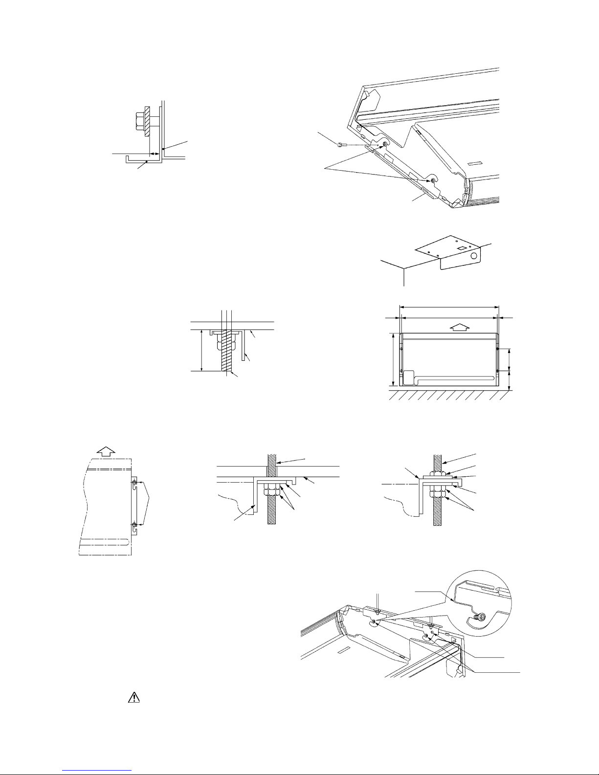
-
58
-
4) Suspension bolt position
a) Using the paper pattern supplied as an accessory as a
criterion, select suspension bolt positions and piping
hole positions, then install the suspension bolts and
make holes for piping. After positioning, remove the
paper pattern.
b) Keep strictly to the suspension bolt lengths specified
below.
(d) Installation
1) Fasten the suspension lugs to the suspension bolts.
Suspension
lug screws (M4)
Suspension
lug mounting
bolt (M8)
Lug for
suspension
Loosening
margin
8~12 mm
Lug for
suspension
Indoor unit
Paper
pattern
Ceiling board
Lug for
suspension
Suspension
bolts
25mm or more
45mm or less
1320
1272
Air supply
2424
Wall
690
290215
Fasten the bolts
to the front of the
slotted holes.
Air supply
Flat washer
(accessory parts)
Ceiling board
*Fasten it securely with double nuts.
Suspension bolts
Lug for suspension
Unit
*Double nuts
Flat washer
(accessory parts)
Flat washer
Nut
*Double nuts
Suspension bolts
Lug for suspension
Unit
3) Remove the suspension lug.
Take out the screws, then loosen the installation bolt.
2) Attach the unit to the suspension lugs.
1 Slide the unit onto the suspension lugs from
the front, hanging it on the bolts.
2 Fasten the unit securely on the left and right
sides with 4 suspension bolts (M8).
3 Tighten the 2 screws (M4) on the left and right
sides.
Lug for
suspension
(M4)
Suspension bolts
(M8)
Lug for
suspension
After sliding the side panels on from the front to rear, fasten them securely with the screws.
<If there is ceiling material>
<If there is no ceiling material>

-
59
-
(e) Refrigerant piping
1) Piping position
2) Piping connection position
Piping can be connection from 3 different directions. Remove the cutout from hole where the piping will be connected
using side cutters or similar tool. Cut a hole for the piping connection in the back cover according to the cutting margin
shown. Cut a hole in the ceiling side in accordance with the position of the piping. Also, after the piping is installed, seal
the space around the piping with putty, etc. to keep dust from getting inside the unit.
(In order to prevent damage to wires from the edges, be sure to use the back cover.)
(If the connection is on the left
side, reverse the slope.)
(The figure shows the case where the
drain hose is on the right side.)
0 ~ 3mm
0 ~ 3mm
Drain piping
(right)
Unit : mm
235 (Liquid pipe)
195 (Gas pipe)
Liquid pipe
271
Slope inside
unit: 10 mm
110
135
Gas pipe
75
76
Drain piping
(left)
53
53
109
10
Drain piping
(For left)
Drain piping
(For left back)
175
19
Top Cover
Unit : mm
Back cutout
Back cover
Cutting margin
Right side
cutout
Top cutout
60
100
120
60
47
60
108
3127
27
(f) Drain piping
1) Drain piping can be connected from the back, right and left sides.
2) When installing drain piping, be sure to use the insulating material supplied for the drain hose and
drain hose clamp.
a) Connect the drain hose fully all the way to the base of the fitting.
b) Fasten the hose securely with the drain hose clamp.
c) Keep strictly within the lengths specified below for the suspension bolts.
3) If drain piping is installed on the left side, change the rubber plug and insulating material (tubular)
from the left side piping connection port to the right side.
Be careful that water doesn’t pour out when the drain plug is removed.
3) In order to make it easier for water to drain out, install the unit so that the water drain side slopes
downward.
● Left-right direction
● Front-rear direction
If the slope is reversed, there is danger of water leaking out.

-
60
-
Use the fitting supplied with the unit to connect the drain hose, fastening it at the lowest point so that there is no slack, and
establishing a 10 mm drain slope. * Keep electrical wiring from running beneath the drain hose.
Be sure to fasten the drain hose down with a clamp.
There is danger of water overflowing the drain hose.
WARNING
After piping has been installed, check to make sure water drains well and that there is no overflow.
Drain hose
Lowest Point
()
Drain hose
Hose Clamp
It can be fastened
from inside or
outside the unit.
10mm
Avoidriding across an elevation
The drain hose
should slope
downward.
Keep free from trape
Do not pipe under water

-
61
-
(3) Satellite ducted type (FDUM)
(i) Selection of installation location
1) Avoid installation and use at those places listed below.
a) Places exposed to oil splashes or steam (e.g. kitchens and machine plants).
Installation and use at such places will incur deteriorations in the performance or corrosion with the heat exchanger or
damage in molded synthetic resin parts.
b) Places where corrosive gas (such as sulfurous acid gas) or inflammable gas (thinner, gasoline, etc.) is gnerated or
remains. Installation and use at such places will cause corrosion in the heat exchanger and damage in molded synthetic
resin parts.
c) Places adjacent to equipment generating electromagnetic waves or high-frequency waves such as in hospitals. Gener-
ated noise may cause malfunctioning of the controller.
2) Select places for installation satisfying the following conditions and, at the same time, obtain the consent on the part of
your client user,.
a) Places where chilled or heated air circulates freely. When the installation height exceeds 3m, warmed air stays close to
the ceiling. In such cases, suggest your client users to install air circulators.
b) Places where perfect drainage can be prepared and sufficient drainage gradient is available.
c) Places free from air disturbances to the return air port and supply hole of the indoor unit, places where the fire alarm
may not malfunction to short circuit.
d) Places with the environmental dew-point temperature is lower than 28˚C and the relative humidity is less than 80%.
( When installing at a place under a high humidity environment, pay sufficient attention to prevention of dewing such
as thermally insulating the unit properly.)
3) Check if the selected place for installation is rigid enough to stand the weight of thew unit.
Otherwise, apply reinforcement using boards and beams before starting the installation work.
620
Inspection
space
830100
1300
(ii) Suspension
Be sure to observe the finished length of the suspension bolts given below.
472
986

-
62
-
1) Fixing the suspension bolt (customer ordered parts M10)
Securely fix the suspension bolt as illustrated below or in another way.
2) Adjusting the unit’s levelness
a) Adjust the out-levelness using a level vial or by the following method.
● Make adjustment so that the relation between the lower surface of the indoor unit proper and water level in the hose
becomes given below.
b) Unless the levelness is adjusted properly, the malfunction of the float switch will occur.
Insert
Hole in anchor bolt
Hole-in plug
Suspension bolt M10
Concrete
Suspension bolt
M10 Washer
M10 nuts
Indoor unit
M10 Spring washer
Suspension bolt M10
Indoor unit
60mm or less
PVC hose
Piping side
Supply water
0 ~ 5 mm
Bring the piping side slightly lower
3) Blower fan tap switch
The following two methods are available in switching the blower
fan tap. Switch to the high-speed tap with one of these methods.
1 Set SW9-4 provided on the indoor unit PCB to ON.
2 By means of function setting from the remote control
unit, set the setting c of “I/U FUNCTION
”
(indoor unit function) to “Hi CEILING 1” (high-speed
tap) as shown right.
For the details of operating procedures, please refer to the installation manual of your remote control unit.
SW9-4
ON
OFF
Fan control,high speed (High ceiling)
Fan control
Function number A Function description B Setting C
01
Hi CEILING SET Hi CEILING 1
(iii) Duct installation
Return air duct
(to be purchased locally)
Supply air duct
(to be purchased locally)
Return air port
with canvas duct
(to be purchased
locally)
Return air port
(to be purchased locally)
Supply air port
(to be purchased locally)
Heat insulation
Indoor unit
Access door

-
63
-
2 Access door
Access door must be provided without fail.
● Dimensions of access door and service space
( See exterior dimensions in page 11 )
1 Supply air duct
● 3-spot with
200 type duct are the standard specifications. Determine the number of spots based on following table.
● Use a band, etc. to connect the indoor unit and the supply air duct flange.
● Conduct the duct installation work before finshing the ceiling.
FDUMA302R
2 ~ 3-spot
(1)
Bad exampleBad example Good example
Notes (1) Shield the central supply air port for 2-spot.
● Limit the difference in length between spots at less than 2:1.
● Reduce the length of duct as much as possible.
● Reduce the number of bends as much as possible. (Corner R should be as larger as possible.)
3 Return air port
¡ When shipped, the return air port lies on the back.
¡ When connecting the duct to the return air port, remove the air filte if it is fitted to return air port.
¡ When placing the return air port to carry out suction from the bottom side, use the following procedure to replace the
return air duct joint and the bottom plate.
¡ Make sure to insulate the duct to prevent dewing on it.
4 Install the specitic supply air duct in a location where the air will circulate to the entire room.
¡ The duct connection is specific to the 200 circular duct.
¡ Conduct the installation of the specific supply air hole and the connection of
the duct before attaching them to the ceiling.
¡ Insulate the area where the duct is secured by a band for dew condensation
prevention.
Remove the screws which fasten
the bottom plate and the duct joint
on the return air port of the unit.
• Replace the removed bottom plate
and duct joint.
• Fit the duct joint with a screw,
fit the bottom plate.
•
Secure with a band,etc.
Supply air
duct

-
64
-
5 Make sure provide an inspection hole on the ceiling. It is indispensable to service electric equipment, motor, functional
components and cleaning of heat exchanger.
6 If a duct is not provided at the return air side but it is substituted with the space over the ceiling, humidity in the space will
increase by the influence of capacity of ventilation fan, strength of wind blowing againat the outdoor air louver, weather
(rainy day) and others.
¡ Moisture in air is likely to condense over the external plates of the unit and to drip on the ceiling. Unit should be
operated under the conditions as listed in the above table and within the limitation of wind volume. When the building
is a concrete strucially immediately after the construction, humidity tends to rise if the space over the ceiling is not
substitued in place of a duct. In such occasion, it is necessary to insulate the entire unit with glass wool (25mm). (Use
a wire net or equivalent to hold glass wool in place.)
¡ It may run out the allowable limit of unit operation (Example: When outdoor air temperature is 35ºCD.B, return air
temperature is 27ºCW.B) and it could result in such troules as compressor overload, etc..
¡ There is a possibility that the supply air volume may exceed the allowable range of operation due to the capacity of
ventilation fan or strength of wind blowing against external air louver so that drainage from be heat exchanger may fail
to reach the drain pan leak outside (e.g. drip on to the with consequential water leakage in the room.)
Notice: Aspecific cover plate is available when changing the 4 spot to the 3 spot, or when changing the 3 spot to the 2 spot.
Note (1) Do not change from 2 spot to 1 spot.
Air conditioner indoor unit
r Supply air port
w Supply air duct
(optional or marketed item)
Ceiling surface
q Return air port
(marketed item)
(with air filter)
e Return air
duct
(marketed item)
t Inspection hole
Return air grille
(Locality)
Return air grille
(option)
Bad example of duct work
w
q
For ventilation
Louver to
outdoor air

-
65
-
7 Return air duct: Use square duct.
8 Return air port with canvas duct
1) Connection of intake and exhaust ducts.
2) Duct connecting position.
< Outside air intake >
a) Use side air intake port.
b) In case of simultaneous intake and exhaust, the side air intake port cannot be used, therefore, take air from the
midway air intake port along the intake duct.
< Exhaust > Make sure to use suction as well.
c) Use a side exhaust port.
3) Duct connection
Use intake and exhaust duct flange of separately sold (for connection of
125mm round duct) to connect 125mm
round duct. The duct clamped by bands must be thermally insulated to prevent dew condensation.
Looking from top of unit
Exhaust port
Side fresh air intake port
Intake duct
(square duct)
Outside air intake
port midway
of return duct
Fig.2Fig.1
(iv) Drain piping
1) Drain piping should always be in a downhill grade (1/50-1/100) and avoid riding across an elevation or makeing traps.
2) When connecting the drain pipe to the unit, pay suffcient attention not to apply excess force to the piping on the unit side.
Also, fix the piping at a point as close as possible to the unit.
3) For drain pipe, use hard PVC general purpose pipe VP-25
which can be purchased locally. When connecting, insert
a PVC pipe end securely into the drain socket before tight-
ening securely using the attached drain hose and clamp.
Adhesive must not be used connection of the drain socket
and drain hose (accessory).
1.5 m ~ 2m
Suspension
bolts
Heat
insulation
A downhill grade
of 1/100 or more
Air vent
Avoid riding across an elevation
Keep free from traps
Do not pipe under water
Drain socket
Level difference part
Drain hose
Joint for VP-25
(local procurement)
Pipe cover (small)[insulation]
(accessory)
Drain socket
Indoor
unit
Clamp
(accessory)
Drain hose piece
(accessory)
Adhesion
VP-25
(local procurement)
Pipe cover [insulation]
(local procurement)
Pipe cover (large)[insulation]
(accessory)
● Good piping
● Improper piping

-
66
-
9) Drainage test
a) During trial operation, make sure that drainage is properly execued and check that leakage is not found at connections.
b) Be sure to carry out a drainage test when installing the system during a heating season.
c) When installing the system in a building under construction, carry out the drainage test before ceiling tiles are in-
stalled.
Remove the grommet.
Be sure to restro it to the original
position after the test is over.
Insert a water filing hose by approx 50 mm and feed water.
(Be sure to insert the water filing hose in a downward direction.)
4) When constructing drain piping for several units, position the common pipe about 100 mm below the drain outlet of each
unit as shown in the sketch below. Use VP-30 or thicher pipe for this purpose.
5) Be sure to provide heat insulation to hard PVC pipes of indoor placement.
6) Do not ever provide an air vent.
7) The height of the drain head may be elevated up to a point 600 mm from the bottom of unit and, when an obstacle exists
in the ceiling space, elevate the piping to avoid the obstacle using an elbow or corresponding gadget. When doing this, if
the stretch for the needed height is too high, the back-flow quantity of drain at the time of interruption of the operation gets
too much and it may cause overflow at the drain pan. Therfore, make the height of the drain pipe withing the distance
given in the drawing below.
8) Avoid positioning the drain piping outlet at a place where generation of odor may stimulated. Do not lead the drain piping
direct into a sewer from where sulfur gas may generate.
VP30
A downhill grade of
1/100 or more
Secure the elevation as high as possible
(approx. 100 mm)
295 ~ 325
Drain hose
Right above
Joints for VP-25
600
(local maximum
height of drain head)
Unit : mm
1 Supply approx 1000cc of water through the outlet of the unit using a feed water pump.
2 Make sure that drainage is proceeding properly at the see-through outlet of the unit.
* Also confirm the revolving sound of the condensate motor when checking the drainage.
3 Then remove the drain plug at lower section of the unit to drain water off. After making sure water is not left, restore
the drain plug to the original position.

-
67
-
Forced drain pump operation
Setup from a unit side.
1 Turn power on after selecting the emergency operation mode with a setting on the indoor unit control PCB (SW9-3 ON) and
disconnecting the CnB connector on the board. Then , the drain pump will start a continuous operation 15 seconds later.
(Note : The blower will also start operation in tandem)
2 When a drain test is completed, reinstate the setting to cancel the emergency operation mode (SW9-3 OFF) and plug in the
CnB connector on the board.
(When electrical work is not completed, connect a convex joint to the drain pipe joint area, arrange an inlet and check leaks and drain connections of the pipe)
Setup from a remote controller side.
Drain pump operation from a remote controller unit is possible. Operate a remote controller unit by following the steps described
below.
1. To start a forced drain pump operation
1 Press the TEST button for three seconds or longer.
The display will change from “
SELECT ITEM”
“
SET”
“
TEST RUN
”
2 Press the
button once while “
TEST RUN
” is displayed, and cause “DRAIN PUMP ” to be displayed.
3 When the SET button is pressed, a drain pump operation will start.
Display: “DRAIN PUMP RUN”
“
STOP”
2. To cancel a drain pump operation.
1 If either SET or ON/OFF button is pressed, a forced drain pump
operation will stop.
The air conditioning system will become OFF.
10
)Drainage from the lower drain socket
Only if the drain pipe can be installed in a downhill grade
(1/50-1/100), the lower drain socket can be used for con-
necting to the drain pipe as illustrated.
(Disconnect the connector for the drain motor)
As shown in the sketch to the right, disconnect the drain
motor connector CnR ( blue color coding).
If the system is started with this connector connected as
is, drain water is discharged out of the upper drain socket
causing a heavy water lekage.
The upper drain socket
A hard PVC general-purpose pipe
Heat insulator
Rubber plug
(Remove the rubber plug)
The lower drain socket
(Piping connection)
Disconnect Condensate
motor connector
CnR (2P Blue)

-
68
-
7) Use a cord clamp to attach the remote controller
cord to the wall.
8) Set the functions according to the types of indoor unit. See Section “Function Setting’’.
(b) Recessed fitting
1) The Electrical box and remote controller (shield
wire must be use in case of extension) are first
embedded.
(1) Selection of installation location
Avoid the following locations
1) Direct sunlight.
2) Close to heating device.
3) Highly humid or water splashing area.
4) Uneven surface.
(2) Installation procedure
(a) Exposed fiting
1) Open the remote controller cover and unscrew
the screw located beneath the switch.
2) Open the remote controller case.
• Put a screw driver (flat-head) into the concav-
ity made on the upper part of a remote controller and twist it lightly to open the casing.
3) The cord of a remote controller can only be
pulled out in the upward direction.
• Cut off with nippers or a knife a thin walled
part made on the upper end of the rmote controller bottom casing, and then remove burrs
with a file or the like.
4) Fix the remote controller bottom casing onto
a wall with two wood screws supplied as accessories.
5) Connect the remote controller to the terminal block. Connect the terminals of the remote controller to the indoor unit with the
same numbers. Because the terminal block
has polarity, the device becomes inoperative
if there are wrong connections.
Terminals: xRed wire, YWhite wire, ZBlack wire
• Use a cord of 0.3mm2 (recommended) -
0.5mm
2
(maximum) for a remote controller
cord. Remove a sheathe of the remote controller cord for the section laid within the remote
controller casing.
Thin walled part
Upper
Lower
Lower case
Two M4 screws
(Head diameter must be 8mm)
(not included)
2) Remote the upper case to the remote controller.
3) Attach the lower case to the Electricl box with
two M4 screws. (Head diameter must be 8 mm).
Choose either of the following two positions in
fixing it with screws.
4) Connect the remote controller cord to the remote
controller.
Refer to [Exposed fitting].
5) Installation work is completed by replacing the
top casing onto the bottom casing as before.
6) Set the function switch according to the type of
the indoor unit. (Refer to 76 page)
Precation in extending the remote controller cord
Maximum total extension 600m.
The cord should be a shielded wire.
● For all types : 0.3mm
2
× 3 cores
Note (1) Use cables up to 0.5mm2 (maximum) for those laid inside
the remote controller unit casing and connect to a different
size cable at a vicinity point outside the remote controller
unit, if necessary.
100.Within 100-200m…………0.55 mm
2
× 3 cores
Within 300m…………0.75 mm
2
× 3 cores
Within 400m…………1.25 mm
2
× 3 cores
Within 600m…………2.05 mm
2
× 3 cores
●
The shielded wire should be grounded at one side only.
t
1.5.2
Installation of wired remote controller
Black: 195mm, White: 205mm, Red: 125mm
6) Replace the top casing as before.
5?HAM
The length of each wire that should be left after a
sheath is removed is as follows:

-
69
-
1.5.3 Installation of outdoor unit
(1) Installation
(a) In selecting an installation location, please pay attention to the following conditions and obtain the
customer’s consent.
1) The place where the foundation can bear the weight of Outdoor unit.
2) The place where there is no concern about leakage of combustible gas.
3) The place where it is not stuffy.
4) The place where free from thermal radiation of other thermal source.
5) The place where flow of drain is allowed.
6) The place where noise and hot air blast do not trouble neighboring houses.
7) The place where there is no obstruction of wind at the air inlet port and air outlet port.
8) A place where it is not subject to strict rules regulating electrical noises.
9) A place at least 5m away from a TV or radio set. (If electrical noises interfere with such an instrument, move it further
away from it)
10) When the unit is installed at the particular location as shown below, corrosion or failure may be caused. Please consult
the dealer from which you purchased the air-conditioner.
a) The place where corrosive gas is generated (hot spring, etc.).
b) The place where wind containing salt blows (seaside area).
c) The place where enveloped by oil mist.
d) The place where there is a machine that radiates electromagnetic wave.
e) A place where inverter-equipped equipment, a captive generator, high-frequency medical equipment, wireless com-
munication equipment or other equipment generating electromagnetic waves is installed.
(b) The minimum space for installation
Select the space considering the direction of refrigerant piping.
Requ¡Restrict the height of obstruction wall in front of the air outlet port to the height of unit or less.
Requ¡Do not enclose around the unit by the obstruction. Secure the top space for 1 m or more.
Requ¡When more than one unit are installed side by side, provide a 250mm or wider interval between them as a service
space. In order to facilitate servicing of controllers, please provide a sufficient space between units so that their top
plates can be removed easily.
Requ¡When installing the unit where there is a concern about the short circuit, attach the guide louver in front of air outlet
port to prevent the short circuit.
Requ¡When installing plural units in a group, secure sufficient intake space to prevent the short circuit.
Requ¡When installing the unit where it is covered by snow, provide appropriate snow break means.
Special instructions for R410A air conditioning systems
● Use only R410A refrigerant. R410A refrigerant is operated at about 1.6 times as high pressure as the conventional refrigerant
is.
● Air conditioning systems using R410A are equipped with different-diameter outdoor unit service valve charge ports and
check joints provided in the units so as to prevent wrong refrigerant from being charged by mistake. To achieve higher
strength resistible to refrigerant pressure, the dimensions of flaring and the across-the-flats measurement of a flare nut have
been changed for refrigerant piping. Therefore, please arrange dedicated R410A tools as listed in the table shown on the
below before you set to installation or service work.
● Do not use a charge cylinder. The use of a charge cylinder will cause the refrigerant composition to change, resulting in
performance degradation falling short of the rated capacity.
● In charging refrigerant, always take out refrigerant from a cylinder in the liquid phase.
Dedicated R410 tools
Gauge manifold
Charge hose
Electronic scale for refrigerant charging
Torque wrench
Flare tool
Protrusion control copper pipe gauge
Vacuum pump adapter
Gas leak sensor
a
b
c
d
e
f
g
h

-
70
-
(d) Carry-in and installation of unit
Pay sufficient attention to the carry-in and moving work of the unit, and always execute work by two persons or more.
1) Carry-in
a) When carrying-in the unit, carry it in as packed condition to the installation site as
near as possible.
b) If you are compelled to carry-in the unit unpacked condition, lift the unit by the rope
using a nylon sling or applying protection plates so that the unit is not marred.
a) To install the unit, secure the legs of unit by below mentioned bolts without fail.
Secure with the anchor bolt.
2) Install the unit directing the air out-
let port at a right angle to the wind
direction.
(c) Location where strong wind blows against the unit
● Where the unit is likely to be subjected to strong winds, guard it from winds with the following measures.
A failure to give protection against winds may cause performance degradation, a rise of high pressure resulting is an
operation interruption, a broken fan, etc.
3) Where the foundation is not stable,
secure the unit with wire, etc.
Wind
direction
1) Install the unit directing the air out-
let port to the wall.
500 or more
Wind
direction
Protection plate
Wood base
Heavier on
the right side
2) Moving
a) The unit is heavier on the right side looking from the front of unit
(air outlet port side). Therefore, sufficient caution is required for
the person who carries the right side of unit. The person who car-
ries the left side must hold the handle of front panle and the conner
pillar with both hands.
3) Bolt securing position
Conner
pillar
Bury the foundation deeper
into the ground.
Make the foundation wider.
Secure with bolts.
(M10 to 12)
Anchor bolt position
(4 places)
Air inlet
Air outlet
Unit : mm
150 580 150
19
380
19
*
Unit:mm
Mark
123
L1 Open Open 500
L2 300 250 Open
L3 100 150 100
L4 250 250 250
Installation
type
L2
L1
L3
L4
Air inlet
Air outlet
Maintenance
space
( )
Air
inlet
*
Ground level (floor level)
Ground level
(floor level)

-
71
-
b) Limit the protrusion height of front side anchor bolts to 15 mm at the maximum.
c) Install the unit firmly so that it does not fall by earthquake and strong wind.
d) Make the concrete foundation by referring the above illustration.
e) Install the unit in level. (The height difference between right and left is within 5 mm.)
f) In an area where temperature drops below zero for several days in a row, install the unit on the concrete base of which
top is elevated by 30mm or more from the ground level (measurement marked with * in the drawing).
(Because of freezing, drain water could otherwise be blocked from running freely).
Piping specification
Maximum one way length
L=50 m or less
Height difference
● When the position of outdoor unit is higher than that of
the indoor unit, keep the difference H=30 m or less.
● When the position of outdoor unit is lower than that of the
indoor unit, keep the difference H=15 m or less.
Indoor unit
Outdoor unit
(2) Refrigerant piping work
Select the piping specification to fit the specification of indoor unit and installation location.
(a) Decision of piping specification
Unit : mm
Outdoor unit model Gas pipe Liquid pipe
FDCVA302HENR ø 15.88 t1.0 ø 9.52 t0.8
(b) Points for attention in installing refrigerant piping
1) Use pipes made of the following material
Material: Phosphorus deoxidized copper seamless pipes (C1220T, JIS
H3300)
2) Please dress the refrigerant piping (both gas and liquid pipes) with a heat
insulating material for prevention of dew condensation. Improper heat
insulation incapable of preventing dew condensation can cause the leaking or dripping of water and a resultant soaking of household effects.
3) Use only a good heat insulating material (120°C or higher) for heat insulation. A poor heat insulating material offers only poor heat insulation
and can cause cable deterioration.
a) The gas pipes can cause dew condensation during a cooling opera-
tion, which may become drain water causing a water-leak accident,
or a risk of burns during a heating operation, if touched accidentally,
with its surface reaching a high temperature because of discharged
gas flowing inside. So, do not fail to dress it with a heat insulating
material to prevent such mishap.
b) Dress the flare joints of the indoor units with a heat insulating mate-
rial (pipe covers) (for both gas and liquid pipes).
c) Dress both gas and liquid pipes with a heat insulating material. In
doing so, leave no gaps between the pipe and the heat insulating material and wrap them, together with the connecting cable, with a dressing tape.
4) When you need to bend a pipe, bend it to the largest possible radius (R100R150) permitted. Do not bend a pipe repeatedly in an effort to shape it
appropriately.
5) In laying pipes, take care to avoid debris, chips or water
from entering the piping system.
6) A unit and a refrigerant pipe are to be flare connected.
Flare a pipe after you have attached a flare nut to the pipe.
The dimensions of flaring for R410A are different from
those for the conventional R407C refrigerant. Although
we recommend the use of flare tools developed specifically for R410A, conventional flare tools can also be used,
if the measurement of protrusion B is adjusted with a protrusion control copper pipe gauge.
7) Tighten a flare joint securely with double spanners. Observe the following tightening torque values for flare nuts:
8) A branching pipe set (option part supplied separately) and
refrigerant piping should be connected by blazing.
9) In blazing pipes, keep nitrogen gas flowing inside the pipes
so that an oxide film may not form on the inner surfaces
of the pipes.
Exterior tape
Gas piping
Liquid piping
Wires for connecting
indoor and outdoor
units
Insulation
A
B
13.2
19.7
ø9.52
ø15.88
0
-
0.4
A
Copper
pipe outer
diameter
Flared pipe end: A (mm)
0~0.5
ø9.52
ø15.88
Copper
pipe outer
diameter
Copper pipe protrusion for flaring: B (mm)
1.0~1.5
With an R410A tool
In the case of a rigid (clutch) type
With a conventional tool

-
72
-
Operation valve
size (mm)
ø9.52 (3/8")
ø15.88 (5/8")
Tightening
torque (N·m)
34~42
68~82
Tightening
angle (° )
30~45
15~20
Recommended length
of a tool handle (mm)
200
300
Do not hold the valve cap area with a spanner.
Please use a torque wrench. If a torque wrench is not
available, fasten the flare nut manually first and then
tighten it further, using the left table as a guide.
10) Tighten a flare joint securely with a double spanner.
a) Do not apply force beyond proper fastening torque in tightening the flare nut.
b) Fix both liquid and gas service valves at the valve main bodies as illustrated on the lower, and then
fasten them, applying appropriate fastening torque.
(c) How to remove the side cover Unscrew a screw from the side cover
(d) Refrigerant pipe connection
● Install a pipe carefully so that it may not touch the unit’s internal components.
● A pipe touching with an internal component can generate abnormal noises or vibrations.
Airtighteness test completed
Vacuuming begins
Vacuuming completed
Vacuum gauge check
When the vacuum gauge's needle pointer creeps up, there is moisture left in the system
or a leak. Pull air again after you have checked the system for a leak and rectified it. Use
a reverse flow stop adapter to prevent the vacuum pump's lubricant oil from flowing into
the refrigerant system.
Please run the vacuum pump for at
least one hour after the vacuum gauge
shows -101kPa or lower. (-755mmHg
or lower)
No increase in the reading of the
vacuum gauge's needle pointer.
(3) Air tightness test and air purge
● Always use a vacuum pump to purge air trapped within an indoor and the refrigerant piping.
(a) Air tightness test
1) When all the flare nuts on both indoor and outdoor unit sides are fastened. Conduct an air-tightness test from the service
valves charge port with the outdoor unit service valves (on both liquid and gas sides) closed tightly to check whether the
system has no leaks.
2) Use nitrogen gas in the air-tightness test. Do not use gas other than nitrogen gas under any circumstances.
Conduct the air-tightness test by applying 4.15MPa (42kg/cm
3
G) of pressure.
3) Do not apply the specified pressure at once, but increase pressure gradually.
a) Raise the pressure to 0.5 MPa, and then stop. Leave it for five minutes to see if the pressure drops.
b) Then raise the pressure to 1.5 MPa, and stop. Leave it for five more minutes to see if the pressure drops.
c) Then raise the pressure to the specified level (4.15 MPa), and record the ambient temperature and the pressure.
d) If the pressure does not drop after the units is left for approximately one day, the airtighteness is acceptable.
When the ambient temperature changes 1˚C, the pressure also changes approximately 0.01 MPa. The pressure. if
changed, should be compensated for.
(b) Air purge
When a vacuum air purge is completed, remove the valve rod cap nuts and open the service valves (both liquid and gas sides)
as illustrated below. After you have made sure that the valves are in the full-open position, tighten the cap nuts (for the valve
rads and charge ports).
Side cover
Fixing screw
⁄
Pipes can only be laid toward
the rear direction.

-
73
-
(c) Charging refrigerant
1) Since R410A refrigerant must be charged in the liquid phase, you should charge it, keeping the container cylinder upside
down or using a refrigerant cylinder equipped with a siphon tube.
2) Charge refrigerant always from the liquid side service port with the service valve shut. When you find it difficult to
charge a required amount, fully open the outdoor unit valves on both liquid and gas sides and charge refrigerant from the
gas (suction) side service port, while running the unit in the cooling mode. In doing so, care must be taken so that
refrigerant may be discharged from the cylinder in the liquid phase all the time. When the cylinder valve is throttled down
or a dedicated conversion tool to change liquid-phase refrigerant into mist is used to protect the compressor, however,
adjust charge conditions so that refrigerant will gasify upon entering the unit.
3) In charging refrigerant, always charge a calculated volume by using a scale to measure the charge volume.
4) When refrigerant is charged with the unit being run, complete a charge operation within 30 minutes. Running the unit
with an insufficient quantity of refrigerant for a long time can cause a compressor failure.
NOTE Put down the refrigerant volume calculated from the pipe length onto the caution label attached on the back
side of the side cover.
(5) Drain piping work
● Execute drain piping by using a drain elbow and drain grommets
supplied separately as optional parts, where water drained from
the outdoor unit is a problem.
In an area where temperature drops below zero for several days in
a row, do not install a drain elbow or grommets. (Because of
freezing, drain water could be blocked from running freely.)
There are 3 drain holes provided on the bottom plate of an outdoor
unit to discharge condensed water.
When condensed water needs to be led to a drain, etc., install the
unit on a flat base (supplied separately as an optional part) or
concrete blocks.
Connect a drain elbow as shown in the illastration and close the
other two drain holes with grommets.
Grommet
Drain elbow
Drain hose(To be arranged on the user's part)
• Open the valve rod until it touches the stopper. You
need not apply lorce to push it further.
• When an operation is completed, replace the cap nut
and tighten it as before.
Open
Hexagonal Head Wrench
(M4)
Liquid/gas operation
(4) Refrigerant quantity
(a) This unit is shipped from the factory with the refrigerant sufficient for an installation involving 30m of
piping, and does not necessitate additional refrigerant charge as long as the pipe length is 30m or less.
(b) When the pipe length exceeds 30m but remains within 50m, add refrigerant according to the table below
(showing an additional quantity required for each meter of the pipe exceeding 30m) by metering for the
quantity determined by the actual pipe length.
(Example) When 302 model unit is used in a new installation involving 45m of piping
Additional charge quantity:0.9kg = (45-30)m 0.06kg/m
Item
302 series
Quantity charged for shipment (for 30m of piping)(kg) 2.95
Additional charge quantity per meter (kg/m) 0.06
Model
Compound pressure gauge Pressure gauge
Gauge manifold
Handle Hi
Gas service valve
Handle Lo
Liquid service valve
Charge port
-
101kPa
(
-
755mmHg)
Charge hose
Charge hose
Vacuum
pump
Check valve
Vacuum adapter
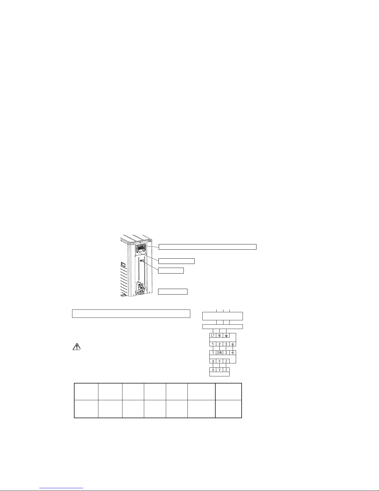
-
74
-
(6) Electrical wiring
Electrical installation work must be performed by an electrical installation service provider qualified by a power provider of the country.
Electrical installation work must be executed according to the technical standards and other regulations applicable to electrical
installations in the country.
1 Do not use any supply cord lighter than one specified in parentheses for each type below.
¡ braided cord (code designation 60245 IEC 51),
¡ ordinary tough rubber sheathed cord (code designation 60245 IEC 53)
¡ flat twin tinsel cord (code designation 60227 IEC 41);
Do not use anything lighter than polychloroprene sheathed flexible cord (code designation 60245 IEC57) for supply cords of
parts of appliances for outdoor use.
2 Ground the unit. Do not connect the grounding wire to a gas pipe, water pipe, lightning rod or telephone grounding wire.
If improperly grounded, an electric shock or malfunction may result.
3 A grounding wire must be connected before connecting the power cable. Provide a grounding wire longer than the power cable.
4 The installation of an impulse withstanding type earth leakage breaker is necessary. A failure to install an earth leakage breaker
can result in an accident such as an electric shock or a fire.
5 Do not turn on the power until the electrical work is completed.
6 Do not use a condensive capacitor for power factor improvement under any circumstances. (It does not improve power factor,
while it can cause an abnormal overheat accident)
7 For power supply cables, use conduits.
8 Do not lay electronic control cables (remote control and signaling wires) and other cables together outside the unit. Laying
them together can result in the malfunctioning or a failure of the unit due to electric noises.
9 Fasten cables so that may not touch the piping etc.
0 When cables are connected, please make sure that all electrical components within the electrical component box are free of
loose connector coupling or terminal connection and then attach the cover securely. (Improper cover attachment can result in
malfunctioning or a failure of the unit, if water penetrates into the box.)
(a) Connect a pair bearing a common terminal number with an indoor-outdoor connecting wire.
(b) In cabling, fasten cables securely with cable clamps so that no external force may work on terminal connections.
(c) Grounding terminals are provided in the control box.
Model
302
series
20
16
3.5
ø1.6 mm
ø1.6 mm × 3
Power source
1phase
220-240V
50Hz
Power cable
thickness
(mm
2
)
Grounding wire
thickness
Max. over
current
(A)
Indoor-outdoor
wire thickness
×
number
Cable length
(m)
Earth leakage breaker
(Harmonic resistant type)
Remote controller
Indoor unit
Outdoor unit
Switchgear or circuit breaker
Power cable, indoor-outdoor connecting wires
● Always perform grounding system installation work
with the power cord unplugged.
CAUTION
Always use an earth leakage circuit breaker designed for
inverter circuits to prevent a faulty operation.
Notes (1) The specifications shown in the above table are for units without heaters. For units with heaters, Please refer to the installation instructions or the
construction instructions of the indoor unit.
(2) Switchgear or circuit breaker capacity which is calculated from MAX. over current should be chosen along the regulations in each country.
(3) The cable specifications are based on the assumption that a metal or plastic conduit is used with no more than three cables contained in conduit and
a voltage drop is 2%. For an installation falling outside of these conditions, please follow the internal cabling regulations. Adapt it to the regulation
in effect in each country.
Grounding terminal
⁄
It is stuck on control box cover.
⁄
Fasen cables so that terminal connections are
not subjected to external force.
Wiring diagram
Wiring clamp
Power source,signal line and ground terminal block

-
75
-
ZYX
Indoor unit
Remote
controller
SW1
M
Remote
controller
SW1
S
ZYX
ZYX
Remote control signal line (with polarity) (Match up X , Y and
Z when making connections.)
Upper
Lower
PCB
SW2
SW1
SW1
M
S
Switch
Function
M
S
Mastor remote controller
Slave remote controller
SW1
Indoor unit (1)
Address [0]
Red
White
Black
Remote controller
ZYX
ZYX
Indoor unit (2)
Address [1]
ZYX
Indoor unit (16)
Address [F]
ZYX
Remote control signal line (with polarity) (Match up X , Y and
Z when making connections.)
(d) Remote controller wiring and connection procedure
1) Master-slave settings when using multiple remote controllers
● Up to 2 remote controllers can be connected for each indoor unit (or group).
a) There are two methods, one where the remote controller signal line (3-wire) for the slave remote controller is taken
from the indoor unit and the other where the signal lines are taken from the master remote controller.
b) Set the SW1 select switch on the slave remote controller on the Slave setting. (It is set on the Master setting at the
factory.)
Note (1) Remote controller sensor activation settings are possible only with the master remote controller. Install the master remote controller in a
location where it can sense the room temperature.
2) Controlling multiple indoor units using a single remote controller.
● Up to 16 indoor units can be controlled with a single remote controller.
a) Run 3-wire remote control lines between each of the indoor units. See “Precation in extending the remote control
cord” on page 68 concerning extended remote control lines.
b) Set the remote controller communications address on “0” ~ “F” using rotary switch SW2 on the indoor unit’s
control board, taking care not to overlap the addresses of any of the units.
c) After turning the power on, press the AIR CON No. button to display the indoor unit’s address. Be sure to confirm
that the settings are displayed correctly in the remote controller by using the
and
buttons to display the
address of each connected indoor unit.

-
76
-
(7) Setting functions using the wired remote controller
(a) The default settings of this unit's functions are as follows: If you want to charge a setting, follow the
procedure found in the installation manual and set to your desired setting.
For the method of setting, please refer to the installation manual of a remote controller unit.
1 Remote controller unit functions (
FUNCTION
)
2 Indoor unit functions (I/U FUNCTION
)
01
02
03
04
05
06
07
08
09
10
11
12
13
14
15
16
17
18
Default
setting
GRILLE SET
AUTO RUN SET
TEMP S/W
MODE S/W
ON/OFF S/W
FANSPEED S/W
LOUVER S/W
TIMER S/W
SENSOR S/W
VENTI SET
TEMP RANGE SET
I/U FAN SPEED
MODEL TYPE
EXTERNAL CONTROL SET
ERROR DISP SET
POSITION
°C/°F SET
INVALID
50Hz AREA ONLY
60Hz AREA ONLY
AUTO RUN ON
AUTO RUN OFF
VALID
INVALID
VALID
INVALID
VALID
INVALID
VALID
INVALID
VALID
INVALID
VALID
INVALID
SENSOR OFF (Invalid)
SENSOR ON (Valid)
INVALID
VALID
NO VENTI
VENTI LINK SET
NO VENTI LINK
DISP CHANGE
NO DISP CHANGE
3 FAN SPEED
2 FAN SPEED
1 FAN SPEED
HEAT PUMP
COOLING ONLY
INDIVIDUAL OPERATION
SAME OPERATION FOR ALL UNITS
ERROR DISP
NO ERROR DISP
FIX (1 OF 4) (4 position stop)
IN MOTION (Free stop)
°C
°F
Grille lift
panel setting
Remote control
sensor setting
Indoor unit
fan speed setting
Louver
control setting
01
03
04
05
06
07
08
09
10
Function
number A
Default
setting
Hi CEILING SET
FILTER SIGN SET
POSITION
EXTERNAL INPUT SET
ROOM TEMP OFFSET
FAN CONTROL
FREEZE PREVENT TEMP
FREEZE PREVENT CONTROL
(Heating room temperature offset)
Heating
fan control
Louver control
setting
STANDARD (Mild mode)
Hi CEILING 1
(Powerful mode)
NO DISPLAY
AFTER 180H
AFTER 600H
AFTER 1000H
1000H→STOP
FIX (1 OF 4) (4 positiion stop)
IN MOTION (Free stop)
LEVEL INPUT
PULSE INPUT
NORMAL OPERATION
VALID
NORMAL OPERATION
TEMP SHIFT +3˚C
LOW FAN
STOP→LOW FAN (Intermittent operation)
TEMP Hi
TEMP Lo
FAN CONTROL ON
FAN CONTROL OFF
Function description B Setting C
Function
number A
Function description B Setting C
()
()
()
()
POWER FAILURE
COMPENSATION SET
()
()
OPERATION PERMISSION
PROHIBITED
Notes(1)
(2)
Setting marked with [] are the default setting.
Setting marked with [
*
] are those that are set automatically
according to an indoor unit or an outdoor unit connected.
Please check default settings with the indoor unit's installation
manual.
Notes(1)
(2)
(3)
Setting marked with [] are the default setting.
Setting marked with [
*
] are those that are set automatically
according to an indoor unit or an outdoor unit connected.
Please check default settings with the indoor unit's installation
manual.
When Item 17 : “ POSITION” is changed, please also
change Item 04 “ POSITION” setting found in
“Indoor unit functions”.
*
*
*
*
*
*
*

-
77
-
(b) Function setting method
1) Stop the air conditioner
2) Press the SET and MODE buttons simultaneously
for 3 seconds or longer.
The screen display will be switched as follows:
“
SELECT ITEM”
“
SET"
“FUNCTION SET
”
3) Press the SET button.
The unit will enter the function setting mode. The
screen display will charge to “
FUNCTION
”.
4) Check which category your desired setting belongs to, “
FUNCTION (Remote controller unit function)” or “I/U
FUNCTION " (Indoor unit function).
5) Press either
or button.
Select either “ FUNCTION
” or “I/U FUNCTION
”.
6) Press the SET button.
7) When “ FUNCTION ” is selected.
1 “DATA LOADING” (blinking)
“
FUNCTION”
“01 GRILLE SET” (Function number: A, Function description: B)
The screen display will be switched like this.
2 Press either
or button.
“Function number: A, Function description: B “from the list of remote controller unit functions will be displayed one
by one. Select a desired function.
3 Press the SET button.
The screen display will be switched as follows:
“
SETTING”
“Setting: C” (ex. “AUTO RUN ON”)
4 Press either
or button.
A list of “Settings: C” will be displayed one by one. Select your desired setting.
5 Press the SET button.
The selected setting is displayed
for 2 seconds, then followed by
“SET COMPLETE” and the
function setting process is com-
pleted.
Then the screen display will be
swiched to “Function number:
A, Function description: B,” s o
if you want to continue to set an-
other function, repeat the steps as
explained above.
To finish the function setting pro-
cess, please proceed to Step 8).
Operating guide message
Function description: B , Settting: C
Function number: A
Previous screen buttonIndoor unit selector button
Confirm Button
Finish Button
Selector button
Start Button
AUTO RUN SET
FUNCTION SET
FUNCTION
I/U FUNCTION
AUTO RUN SET
AUTO RUN ON
AUTO RUN ON AUTO RUN OFF
SET COMPLETE
Function number: A
Function description: B
* When “ AUTO RUN SET ” is selected.
Setting: C

-
78
-
When “I/U FUNCTION ” is selected.
1 The screen display will be switched as follows:
“
I/U SELECT” “
SET”
“I/U No.00” (blinking)
2 Press either
or button.
Select the indoor unit number that you want to change settings. If only one indoor unit is connected, the indoor unit
number will not charge, so please proceed to Step 3.
If “ALL I/U
” is selected while indoor group control is in effect, you can set all units to the same settings.
3 Press the SET button.
Indoor unit number indication will change from blinking to lit continuously, The screen display will be switched as
follows:
"DATA LOADING" (blinking for about 2 to 23 seconds)
“ FUNCTION” “01 Hi CEILING SET”
(Function number: A, Function description: B)
4 Press either
or button.
“Function number: A, Function description: B” from the list of indoor unit functions will be displayed one by one.
Select a desired function.
5 Press the SET button.
The screen display will be switched as follows: “
SETTING” “Setting: C” (ex. “STANDARD”)
6 Press either
or button.
A list “Setting: C” will be displayed one by one. Select your desired setting.
7 Press the SET button.
The selected setting is displayed for 2 seconds, then followed by “SET COMPLETE” and the function setting process is
completed.
Then the screen display will be switched to “Function number: A, Function description: B” so if you want to continue to set
another function, repeat the stepa as explained above. To finish the function setting process, please proceed to Step 8).
8 Press AIR CON No. button.
The screen display will go back to the indoor unit selection screen (e,g. “ I/U No.00”).
If you want to continue to set another indoor unit, please follow the steps explained above.
8) Press the ON/OFF button.
This ends a function setting process. Even if a function setting process is not completed, this ends the process.
Please note that any setting that is not completed will become void.
● Pressing the RESET button during a function setting process will allow you to go back the previ-
ous step. Please note that any setting that is not completed will become void.
● Method of checking the current setting
While following the above mentioned step, the setting that appears when the SET button is pressed for each “Func-
tion number: A, Function description: B” is the current setting “Stting: C”. (When "ALL I/U
" is selected, the
setting of the indoor unit with the lowest number is displayed)
● Settings are stored in the controller and not lost even a power outage occurs.
I/U No.00
Hi CEILING SET
Function number: A
Function description: B
* When “ Hi CEILING SET” is selected.
STANDARD
Settings: C

-
79
-
(c) Changing the remote control set temperature range
1) It is possible to change the set temperature range using the remote control.
a) The upper and lower set temperature limits can be set from the remote control.
Upper limit value setting: Effective during heating. The temperature can be set within a range of 20~30ºC.
Lower limit value setting: Effective when running in modes other than the heating mode (AUTO, COOL, FAN, DRY): The
temperature can be set within a range of 18~26ºC.
b) If the upper and lower limits are set using this function, the following controls are active.
2) When and BTEMP RANGE SET under “
FUNCTION” the function setting mode is DISP CHANGE
a) If you are setting the upper limit,
q If a temperature that is greater than the upper limit during heating is set from the remote control.
The unit runs for 30 minutes at the set temperature, then it automatically transmits the upper limit temperature. The
display on the remote control also approaches that temperature.
w During heating, if the upper limit value is set at a temperature below the upper limit value:
The set temperature is transmitted.
b) If the lower limit is set
q If a temperature that is lower than the lower limit value is set from the remote control. When running in an operation
mode other than the heating mode: the unit runs at the set temperature for 30 minutes, then it automatically transmits the lower limit temperature.
w If a temperature that is higher than the lower limit value is set when running in a mode other than the heating mode:
It transmits the set temperature.
3) When and BTEMP RANGE SET under the “
FUNCTION” the function setting mode is NO DISP CHANGE.
a) If the upper limit is set
q During heating, if a temperature that is higher than the upper limit is set from the remote control:
The upper limit value is transmitted. However, the remote control display does not approach the upper limit value,
but remains on the set temperature.
w During heating, if the temperature is set at a value lower than the upper limit value:
The set temperature is transmitted.
b) If the lower limit is set
q When in an operating mode other than the heating mode, if a temperature that is lower than the lower limit value is
set from the remote control:
The lower limit value is transmitted. However, the remote control display does not approach the lower limit value,
but remains on the set temperature.
w When in an operating mode other than the heating mode, if a temperature that is higher than the lower limit value is set:
The set temperature is transmitted.
4) Setting the upper and lower limit values
a) Stop the air conditioner, then press the SET and MODE buttons simultaneously for 3 seconds or longer. If you press “
SELECT ITEM” “
SET”
“FUNCTION SET
” the display changes.
b) Press the
button, then change the “TEMP RANGE
“ display.
c) Press the SET button and enter the temperature range setting mode.
d) Using the
buttons, select the “Hi LIMIT SET
” or “Lo LIMIT SET
,” then fix it by pressing SET.
e) If you selected “Hi LIMIT SET,” (enabled during heating)
q “
SET UP” “Hi LIMIT 28°C ” (blinking) is displayed.
w Using the “
” temperature setting buttons, select the upper limit value. Display Example: “Hi LIMIT 26ºC
“ (blinking)
e Press the SET button to fix the setting. Display example: “Hi LIMIT 26ºC” (lights up for 2 seconds)
After the fixed upper limit value lights up for 2 seconds, the display returns to the “Hi LIMIT SET
” display in
item d).
f) If “Lo LIMIT SET
” was selected (enabled during COOL, DRY and FAN)
q “
SET UP” “Lo LIMIT 20°C
” (blinking) is displayed.
w Using the
temperature setting buttons, select the lower limit. Display example: “Lo LIMIT 24ºC
” (blinking)
e Press the SET button to fix the setting. Display example: “Lo LIMIT 24ºC” (lights up for 2 seconds)
After the fixed lower limit value lights up for 2 seconds, the display returns to the “Lo LIMIT SET
” display in
item d).
g) Pressing the ON/OFF button stops the operation.
(Operation stops even if the ON/OFF button is pressed during setting, and the stopped state returns. However, if setting is
not completed, it is not valid, so use caution.)
S If the RESET button is pressed during setting, the previous setting screen is displayed.

-
80
-
12
Function No. A
(Example) If the upper limit is set at 28°C
Function Contents B Setting Contents C
TEMP RANGE SET
DISP CHANGE
NO DISP CHANGE
Control Contents
The remote controller’s display and sent
data upper limit changes to 28°C.
The remote controller’s display upper
limit remains at 30°C and only the upper
limit of the sent data is changed to 28°C.
• If the RESET button is pressed during a setting operation, the display returns to the previously displayed setting screen.
However, settings which have not been fixed become invalid, so exercise caution.
* If “NO DISP CHANGE” is selected in No. 12, “TEMP RANGE SET” of the remote controller’s functions, of the
function setting modes, the remote controller’s display does not change even if the temperature range has been changed.
(8) Checking operation data
Operation data can be checked with remote controller unit operation.
1 Press the CHECK button.
The display change from “
SELECT ITEM”
“
SET"
“OPERATION DATA
”.
2 Press the SET button while “OPERATION DATA
” is displayed.
3 The display will change to “I/U No. 00
” (blinking indication).
Select the indoor unit number you want to have data displayed with the
button.
(When only one indoor unit connected, the indoor unit number displayed on the screen will not change.)
4 Determine the indoor unit number will the SET button.
(The indoor unit number changes from blinking indication to continuous indication.)
“DATA LOADING” (A blinking indication appears while data is loaded)
“OPERATION DATA
” appears and data number 01 is displayed.
5 Upon operation of the
button, the current operation data is displayed in order from Data number 01.
The items displayed are as follows:
* Depending on models, the items that do not have corresponding data are not displayed.
6 To display the data of a different indoor unit, press the AIR CON No. button, which allows you to go back to the indoor unit
selection screen.
7 Pressing the ON/OFF button will stop displaying data.
Pressing the RESET button during remote controller unit operation will undo your last operation and allow you to go back to
the previous screen.
→

-
81
-
Number
01
02
03
04
05
07
11
21
22
23
24
27
28
29
31
32
34
35
36
37
(Operation mode)
(Indoor unit heat exchanger temperature 1)
(Indoor unit heat exchanger temperature 2)
(Indoor unit fan speed)
(Indoor unit operation hours)
(Outside air temperature)
(Outdoor unit heat exchanger temperature 1)
(Outdoor unit heat exchanger temperature 2)
(Discharge pipe temperature)
(Outdoor unit fan speed)
(Compressor operation hours)
(Expansion valve opening 1)
SET TEMP
RETURN AIR
I/U HEAT EXCH 1
I/U HEAT EXCH 2
I/U FAN
TOTAL I/U RAN
OUTDOOR
O/U HEAT EXCH 1
O/U HEAT EXCH 2
COMP HERTZ
DISCHARGE
DOME BOTTOM
CT
O/U FAN
SILENT MODE ON/OFF
63H1 ON/OFF
DEFROST ON/OFF
TOTAL COMP RUN
EEV 1
Data item
SW5-3
ON
OFF
Function
Cooling during a test run
Heating during a test run
Normal or After the test operation
SW5-4
OFF
ON
-
(9) Test run
(a) Test run from an outdoor unit.
1) Test run method
a) A test run can be initiated from an outdoor unit by using SW5-3 and SW5-4 for on-site setting.
b) Switching SW5-3 to ON will start the compressor.
c) The unit will start a cooling operation, when SW5-4 is OFF, or a heating operation, when SW5-4 is ON.
d) Do not fail to switch SW5-3 to OFF when a test run is completed.
1) Cooling test operation procedure
Carry out the following test operation procedure using the remote controller.
a) Starting the cooling test operation
1 Press the ON/OFF button to start operation.
2 Press the MODE button and select “ (COOL)”.
3 Press the TEST button continuously for 3 seconds or longer.
The display changes from “
SELECT ITEM”
“
SET"
“
TEST RUN
”.
4 When “
TEST RUN
” is displayed, press the SET button to begin the cooling test operation.
The display shows “
TEST RUN.”
b) Canceling the cooling test operation
Pressing the ON/OFF button or the TEMP
button ends the cooling test operation.
The “
TEST RUN” display is cleared.
(b) Test run from remote controller.

-
82
-
Indoor unit
Outdoor unit
Gas line
Liquid line
Charge port
Charge hose
Charge hose
Gauge manifold
Charge valve
Vacuum adapter
Vacuum
pump
Handle Lo
Handle Hi
Refrigerant
cylinder
12
3
A
1.6 MAINTENANCE DATA
1.6.1 Servicing
(1) Evacuation
The evacuation is a procedure to purge impurities, such as noncondensable gas, air, moisture from the refrigerant equipment by
using a vacuum pump. Since the refrigerant R410A is very insoluble in water, even a small amount of moisture left in the refriger-
ant equipment will freeze, causing what is called ice clogging.
Evacuation procedure
Make sure that the both service valves of gas and liquid line are fully opened.
(a) Check to ensure that there is no internal pres-
sure in the unit. If there is an internal pres-
sure, it should be relived through the service
port.
(b) Connect the charging hose of the gauge mani-
fold to the service port of the gas piping.
Close high pressure valve 2 of gange mani-
fold.
(c) Connect the charging hose A to a vacuum
pump.
Repeat evacuation in the following sequence.
Notes (1) Do not use the refrigerant pressure to expel air.
Notes (2) Do not use the compressor for evacuation.
Notes (3) Do not operate the compressor in a vacuum condition.
Vacuuming begins
Vacuuming completed
Vacuum gauge check
When the vacuum gauge's needle pointer creeps up,
there is moisture left in the system or a leak. Pull air
again after you have checked the system for a leak and
rectified it. Use a reverse flow stop adapter to prevent
the vacuum pump's lubricant oil from flowing into the
refrigerant system.
Please run the
vacuum pump for at
least one hour after
the vacuum gauge
shows -101kPa or
lower. (-755mmHg or
lower)
No increase in the
reading of the
vacuum gauge's
needle pointer.

-
83
-
(2) Refrigerant charging
(a) After the evacuation shown in the above, change the connection of the charge hose A to the refrigerant cylinder.
(b) Purge air from the charge hose A.
First loosen the connecting portion of the charge hose at the gauge manifold side and open valve 3 for a few seconds, and
then immediately retighten it after observing that gas has blown out from loosened connecting portion.
(c) Open valves 1 and 3 then gas refrigerant begins flowing from the cylinder into the unit.
When refrigerant has been charged into the unit to some extent, refrigerant flow becomes stagnant. When that happens, start
the compressor in cooling cycle until the system is filled with the specified amount of gas, then close valves 1 and 3 and
remove the gauge manifold. Cover the service port with caps and tighten them securely.
(d) Check for gas leakage by applying a gas leak detector around the piping connection.
(e) Start the air conditioner and make sure of its operating condition.
1.6.2 Trouble shooting for refrigerant circuit
(1) Judgement of operating condition by operation pressure and temperature difference
Making an accurate judgement requires a skill that is acquired only after years of experience, one trouble may lead to an another
trouble from a single trouble source and several other troubles may exist at the same time which comes from a undetected different
trouble source.
Filtering out the trouble sources can be done easier by comparing with daily operating conditions. Some good guides are to judge
the operating pressure and the temperature difference between suction air and delivery air.
Following are some pointers,
Pressure
Trouble cause
High side
●
Low side
●
High side ● Ineffective compression
Low side ● (defective compressor)
High side ●
Low side ●
High side
●
Low side
●
High side
●
Low side ●
1) Too high temperature of room
1) Insufficient refrigerant in circuit
2) Clogging of strainer
3) Gas leakage
4) Clogging of air filter (in cooling)
5) Decrease in heat load (in cooling)
6) Locking of indoor fan (in cooling)
1) Locking of outdoor unit fan (in cooling)
2) Dirty outdoor heat exchanger (in cooling)
3) Mixture of non condensable gas (air etc.)
1) Excessive overcharging of refrigerant
2) Mixture of non condensable gas (air etc.)
Indication
Circuit
Too low
A little low
Normal
A little
high
Too high

-
84
-
(1) Selfdiagnosis function
(a) Check Indicator Table
Whether a failure exists or not on the indoor unit and outdoor unit can be know by the contents of remote controller eroor code, indoor/outdoor unit green LED (power pilot lamp
and microcomputer normality pilot lamp) or red LED (check pilot lamp).
1) Indoor unit side
Outdoor unit LEDIndoor unit LED
Green
Keeps flashing
Keeps flashing
Keeps flashing
Keeps flashing
Keeps flashing
Keeps flashing
Keeps flashing
Keeps flashing
Keeps flashing
Keeps flashing
Keeps flashing
Red
Stays OFF
Stay OFF or Lights
continuously
Green
Keeps flashing
Keeps flashing
Keeps flashing
Keeps flashing
Keeps flashing
Stays OFF
Keeps flashing
Keeps flashing
Keeps flashing
Keeps flashing
Keeps flashing
Keeps flashing
*3 time flash
Stays OFF
2 time flash
2 time flash
2 time flash
1 time flash
1 time flash
1 time flash
Stays OFF
Stays OFF
Stay OFF
Red
Stays OFF
Normal
Indoor unit PCB fault
Outdoor unit microcomputer failure
Indoor unit heat exchanger thermistor failure
Indoor unit return air thermistor failure
The float SW operates (with FS only). Drain up kit wiring fault.
Indoor / outdoor transmission error.
Stays OFF
Stays OFF
Stays OFF
2 time flash
Stays OFF
Stays OFF
Stays OFF
Stays OFF
Stays OFF
Stays OFF
Stays OFF
Remote
controller
error code
No-indication
LCD flashes
continuously
or is off.
E1
E5
E6
E7
E9
E10
E28
Cause
Keeps flashing Keeps flashing1 time flash Stays OFF
E8
Stays OFF Stays OFF Stays OFF
Power OFF, L phase wiring is open, power source failure
Stays OFF
Remote controller wires X and Y are reversely connected. *For wire breaking at
power ON, the LED is OFF. Remote controller wire is open. (X wire breaking : A
beep is produced and no indication is made. Z wire breaking : No beep and no
indication) The remote controller wires Y and Z are reversely connected.
Keeps flashing Keeps flashingStays OFF 2 time flash
Poor connection or disconnection in wires connecting the indoor and outdoor
units.
When multiple remote controllers are used for control, the power supply to some
indoor units is OFF.
When multi-unit control by remote controller is performed, the number of units is
over (more than 17 units). Two remote controller are provided for one controller is
performed.
Outdoor unit control PCB is faulty when the power is turned on, or the inverter
parts are faulty.
Heating overload (indoor heat exchanger temperature is abnormally high) and
indoor heat exchanger thermistor is faulty.
Remote controller thermistor failure
Keeps flashing
Keeps flashing
Stays OFF
Stays OFF
E16
Fan motor is faulty (FDTC or FDKN type).
Communications are faulty between master and slave indoor units
Keeps flashing
Keeps flashing
3 time flash
Stays OFF
E14
1.6.3 Diagnosing of microcomputer circuit

-
85
-
Outdoor unit LEDIndoor unit LED
Green
Keeps flashing
Keeps flashing
Keeps flashing
Keeps flashing
Keeps flashing
Keeps flashing
Keeps flashing
Keeps flashing
Keeps flashing
Keeps flashing
Keeps flashing
Keeps flashing
Keeps flashing
Keeps flashing
Red Green
Stays OFF
Stays OFF
Stays OFF
Stays OFF
Stays OFF
Stays OFF
Stays OFF
1 time flash
1 time flash
1 time flash
1 time flash
1 time flash
1 time flash
1 time flash
Red
Outdoor unit power supply open phase, Noise filter defect
Discharge temperature abnormality.
Discharge pipe thermistor failure
63H1 operation, Operation with service valve open
Outdoor air temperature thermistor failure
DC fan motor abnormal.
Remote
controller
error code
E34
E36
E37
E38
E39
E40
E48
Cause
Keeps flashing Keeps flashing
Stays OFF 1 time flash
E35
Keeps flashing
Stays OFF 1 time flash
Current (Abnormalities in a compressor over current)
E42
Keeps flashing
Keeps flashing
Keeps flashing
Stays OFF 1 time flash Inverter communications error
E45
Keeps flashing
Keeps flashing
Stays OFF 1 time flash
Low voltage abnormal or low voltage sensor disconnected
E49
Keeps flashing
Keeps flashing
Stays OFF 1 time flash
Inverter PCB abnormal
E51
Keeps flashing
Keeps flashing
Stays OFF 1 time flash
Suction pipe temperature thermistor disconnected
E53
Keeps flashing
Keeps flashing
Keeps flashing
Keeps flashing
Stays OFF
Stays OFF
1 time flash
5 time flash
Low pressure sensor disconnected or abnormal
Compressor start up error
E54
E59
Outdoor unit heat exchanger thermistor
failure
Outdoor heat exchanger temperature is high or outdoor heat exchanger thermistor
is faulty.
Keeps flashing
Keeps flashing
Stays OFF 1 time flash A/F module over-current error
E47
2) Outdoor unit side

-
86
-
Section Display section
Error code of remote controller
Inspection LED (red) of indoor unit PCB
Inspection LED (red) of outdoor unit PCB
• Displays the error of higher priority (When plural errors are persisting)
• Displays the present errors.
(When a new error has occurred after the former error was reset.)
Error detail Error code Timing of error detection
Wrong connection between the indoor and
outdoor units.
“ WAIT ”
Normally, 30 seconds after the power is turned ON.
Normally after the power is turned ON (during communications).
Broken wire of heat exchanger thermistor
Drain error (float switch motion)
No communications even once with the outdoor unit.
After 1 or more communications of the indoor unit with the remote controller
following power on, transmission errors cause an interruption for 2 minutes.
After communications with the outdoor unit 1 or more times, communications
are abnormal continuously for 2 minutes.
When an input temperature of –50°C or lower is measured by the return air
thermistor is measured for 5 seconds or longer within 60 minutes after the
first detection.
When an input temperature of –50°C or lower is measured by the heat
exchanger thermistor is measured for 5 seconds or longer within 60 minutes
after the first detection.
Transmission error of remote controller
indoor unit
Transmission error between indoor/outdoor
units
The number of connected indoor units
exceeds the connection limit (when
multiple units are control by a single remote
controller).
Broken wire of indoor unit return air
thermistor
···········
···········
Error detail Error code Timing of error detection
Broken wire of heat exchanger thermister
Broken wire of discharge pipe thermistor
Broken wire of suction pipe thermistor
Broken wire of low pressure sensor
Broken wire of outdoor air temperature
thermistor
When a thermistor input temperature of –30°C or lower is measured for 5
seconds or longer 3 times within 40 minutes after the 1st detection between 2
minutes and 2 minutes 20 seconds after compressor operation starts.
When a thermistor input temperature of –50°C or lower is measured for 5
seconds or longer 3 times within 40 minutes after the 1st detection between 2
minutes and 2 minutes 20 seconds after compressor operation starts.
When a thermistor input temperature of –10°C or lower is measured for 5
seconds or longer 3 times within 40 minutes after the 1st detection between
10 minutes and 10 minutes 20 seconds after compressor operation starts.
When a thermistor input temperature of –50°C or lower is measured for 5
seconds or longer 3 times within 40 minutes after the 1st detection between
10 minutes and 10 minutes 20 seconds after compressor operation starts.
When a sensor is OV or lower or 3.49V or higher continously for 5 seconds or
longer 3 times within 40 minutes after the 1st detection between 2 minutes
and 2 minutes 20 seconds after compressor operation starts.
(b) Display sequence of error, inspection display lamp
1) One kind error
Display corresponding to the error is shown.
2) More than one errors.
3) Timing of error detection
● Indoor unit side.
● Outdoor unit side.

-
87
-
4) Recording and reset of error
Notes (1) Priority is in the order of E1 > ... > E10 > ... > E59.
(2) Procedures of trouble diagnosis
When any error occurs, inspect in following sequence. Detailed explanation on each step is given later in this text.
Error display Memory Reset
Error code of remote
controller
Indoor unit inspection lamp
(red)
• Saves in memory the mode
(1)
of higher
priority
• Stop the unit operation by pressing the ON/OFF switch of remote
controller.
• Operation can be started again if the error has been reset.
• Saves in memory the mode
(1)
of higher
priority
• Cannot save in memory
Outdoor unit inspection lamp
(red)
Error
Check of inspection display [In-
door/outdoor unit PCB, remote
controller or Indication board]
Power supply check
(indoor/outdoor unit)
Replacement or repair of defective
parts Test run/adjustment
Check of unit
controller
Check remote controller for
abnormal operation data.
Indoor unit
Outdoor unit
: Press the ON/OFF button on the remote controller. Or disconnect and reconnect the power supply connector
(CNW1 or CNW0) on the indoor unit control PCB or turn the main power supply OFF.
: Turn the main power supply OFF.
(3) Error diagnosis procedures at the indoor unit side
To diagnose the error, measure the voltage (AC, DC), resistance, etc. at each connector around the PCB of indoor unit based on the
inspection display or the operation state of unit (no operation of compressor or blower, no switching of 4-way valve, etc.) If any
defective parts are discoverd, replace with the assembly of parts as shown below.
(a) Single-unit replacement parts for PCB of indoor unit. (Peripheral electric parts for circuit board.)
Indoor unit printed circuit board, thermistor (air return, heat exchanger), operating switches, limit switches, transformers,
fuses.
Note (1) Use normal inspection methods to determine the condition of strong electrical circuits and frozen cycle parts.
(b) Replacement procedure of indoor unit microcomputer printed circuit board
Microcomputer printed circuit board can be replaced with following procedure.
(i) Confirm the parts numbers.
PJA505A142ZA
PJA505A122ZD
PJA505A128ZC
Parts number
FDTC
FDT
FDEN
Model
FDUM
FDKN
–
Model
PJA505A131ZC
PHA505A018ZF
–
Parts number

-
88
-
Parts layout on the indoor unit PCB
Model: FDTC series
Input signal - Reverse invalid
Input signal - Run stop
Heating thermostat OFF-Lo
Heating thermostat OFF-Stop, Lo
Normal operation operable
Operation permission prohibited
Normal
Heating temp. +3
Louver free stop control - Invalid
Louver free stop control - Effective
Freeze prevention fan control activated.
Freeze prevention fan control deactivated.
Louver position : Normal
Louver position : For wind 1
J1 (SW7-1)
J2 (SW7-2)
J3 (SW7-3)
J4 (SW7-4)
J5 (SW8-1)
J6 (SW8-2)
J7 (SW8-3)
With
None
(1)
With
None
(1)
With
None
(1)
With
None
(1)
With
None
(1)
With
None
(1)
With
None
(1)
Name Function
Note (1)
(2)
“None” means that jumper wire is not provided on the PCB or the
connection is cut
The replacement board is not equipped with jumpers J1 ~ J7. Instead,
SW7 and 8, with the same functions as jumpers J1~J7, are used in the
position where the jumpers were previously. Set SW7 and 8 locally in
accordance with the above table.
Note (1) It is normally ON only in the case of SW9-4.
Setting time : 1000hrs. (Unit stop)
Setting time : 1000hrs. (Display)
Setting time : 600hrs. (Display)
Setting time : 180hrs. (when shipped from factory)
SW5-4SW5-3
ON
OFF
ON
OFF
ON
OFF
Switch
Function
Emergency operation
Normal
Fan control : Powerful mode
Fan control : Mild mode
SW9-3
SW9-4
SW10-1 (J9)
Switch Function
Auto swing function - None
Auto swing function - With
Remote controller air flow –
Remote controller air flow 1 speed
Remote controller air flow 2 speed
Remote controller air flow 3 speed
SW10-3
(J11)
SW10-2
(J10)
OFF
ON
OFF
ON
OFF
ON
OFF
ON
ON
OFF
ON
OFF
Switch
Function
Slave c
Slave b
Slave a
Master
SW5-2SW5-1
ON
OFF
ON
OFF
ON
OFF
● Control change switch (SW5, SW9, SW10)
Function of DIP switch SW5 (Usually all turned OFF)
Function of DIP switch SW9
● Change by the jumper wire
Function of DIP switch SW10 (Usually all turned ON)
CNI
CNQ
LED2
LED1
CNT CNV
CNJ
CNR
CNW0 CNW1
CNM1CNM1
CNM2
CNW2
CNH CNN1
CNZ CNB
SW5
SW2
SW9
SW10SW7
SW8
PCB power supply
connector
(Primary side)
Power supply
Fan motor
Fan motor
Drain motor
Louver motor
Connector
Heat exchanger
thermistor,Return
air thermistor
(ThI-R1,ThI-A)
Heat exchanger
thermistor
Float switch
DPI switch
Remote controller
(ThI-R2)
(SW9)
J5,J6
(SW8)
J1~J4
(SW7)
DPI switch
(SW5)
DPI switch
(SW10)
(CNT)
PCB power supply
connector
(Secondary side)

-
89
-
CNM3
52X6 52X1 52X2 52X3
52X4
52X8-2
PC3
IC2
C2
X1
CNE
F2
F1
Z2D
Z3D
Z4D
Z5D
R16
ZD1
CNJ
D2
IC7
TVS1
CNM2
CNW8
CNT
IC9
J8
1234
J10
J11
J12
CNR
IC12
CNG
LED2
LED1
CNW9
C13
PC5
C12
C1
L1
C58
IC3
C4
C3
CNY
CNI
CNH CNN1
SW2
SW10
SW5
1234
SW7
J5J6J7
J8
SW8
J1J2J3
J4
SW9
IC11
IC8
CNB
C11
C41
KN1
CNV
52X7
52X8-1
CNW7
TM1
PC2 PC1
R17
C23
L2
ON
ON
C5
Power supply PCB
(CNW8)
Connector
(CNT)
Address switch
(SW2)
Heat exchanger thermistor,
Return air thermistor
(Thi-R1, Thi-A)
Heat exchanger
thermistor
(Thi-R2)
J9~J11
(SW10)
DIP switch
(SW5)
J5~J7
(SW8)
DIP switch
(SW9)
J1~J4
(SW7)
Remote
controller
Louver motor
To power supply
(CNW7)
Fan motor
Input signal - Reverse invalid
Input signal - Run stop
Heating thermostat OFF-Lo
Heating thermostat OFF-Stop, Lo
Normal operation operable
Operation permission prohibited
Normal
Heating temp. +3
Louver free stop control - Invalid
Louver free stop control - Effective
Freeze prevention fan control activated.
Freeze prevention fan control deactivated.
Louver position : Normal
Louver position : For wind 1
J1 (SW7-1)
J2 (SW7-2)
J3 (SW7-3)
J4 (SW7-4)
J5 (SW8-1)
J6 (SW8-2)
J7 (SW8-3)
With
None
(1)
With
None
(1)
With
None
(1)
With
None
(1)
With
None
(1)
With
None
(1)
With
None
(1)
Name Function
Note (1)
(2)
“None” means that jumper wire is not provided on the PCB or the
connection is cut
The replacement PCB is not equipped with jumpers J1 ~ J7. Instead,
SW7 and 8, with the same functions as jumpers J1~J7, are used in the
position where the jumpers were previously. Set SW7 and 8 locally in
accordance with the above table.
Note (1) It is normally ON only in the case of SW9-4.
Slave c
Slave b
Slave a
Master
SW5-2SW5-1
ON
OFF
ON
OFF
ON
OFF
Setting time : 1000hrs. (Unit stop)
Setting time : 1000hrs. (Display)
Setting time : 600hrs. (Display)
Setting time : 180hrs. (when shipped from factory)
SW5-4SW5-3
ON
OFF
ON
OFF
ON
OFF
Switch
Function
Emergency operation
Normal
Fan control : Powerful mode
Fan control : Mild mode
SW9-3
SW9-4
SW10-1 (J9)
Switch Function
Auto swing function - None
Auto swing function - With
Remote controller air flow –
Remote controller air flow 1 speed
Remote controller air flow 2 speed
Remote controller air flow 3 speed
SW10-3
(J11)
SW10-2
(J10)
OFF
ON
OFF
ON
OFF
ON
OFF
ON
ON
OFF
ON
OFF
Switch
Function
● Control change switch (SW5, SW9, SW10)
Function of DIP switch SW5 (Usually all turned OFF)
Function of DIP switch SW9 (Usually all turned OFF)
● Change by the jumper wire
Function of DIP switch SW10 (Usually all turned OFF)
Model: FDT series

-
90
-
CNW1
CNJ2CNM3CNRCNV
LED1
LED2
CNB CNW2
KN1
52X5
52X352X252X252X652X4
52X8-2
52X8-1
52X7
L3
F1
ZNR
CNW0
CNM1
L2
L1
C57
CNQ CNT
CNH CNN1
SW2 SW5
CNE
SW8
SW7SW9SW10
IC8IC7
PCB power supply connector
(Primary side)
PCB power supply
connector
Heat exchanger thermistor,
Return air thermistor
(Thl-R1, Thl-A)
DIP switch
(SW5)
J5~J7
(SW8)
J1~J4
(SW7)
DIP switch
(SW9)
J9~J11
(SW10)
Address switch
(SW2)
Connector
(CNT)
Heat exchanger thermistor
(Thl-R2)
Remote controller
(Secondary side)
Power supply
Fan motor
Model: FDEN series
Input signal - Reverse invalid
Input signal - Run stop
Heating thermostat OFF-Lo
Heating thermostat OFF-Stop, Lo
Normal operation operable
Operation permission prohibited
Normal
Heating temp. +3
Louver free stop control - Invalid
Louver free stop control - Effective
Freeze prevention fan control activated.
Freeze prevention fan control deactivated.
Louver position : Normal
Louver position : For wind 1
J1 (SW7-1)
J2 (SW7-2)
J3 (SW7-3)
J4 (SW7-4)
J5 (SW8-1)
J6 (SW8-2)
J7 (SW8-3)
With
None
(1)
With
None
(1)
With
None
(1)
With
None
(1)
With
None
(1)
With
None
(1)
With
None
(1)
Name Function
Note (1)
(2)
“None” means that jumper wire is not provided on the PCB or the
connection is cut
The replacement PCB is not equipped with jumpers J1 ~ J7. Instead,
SW7 and 8, with the same functions as jumpers J1~J7, are used in the
position where the jumpers were previously. Set SW7 and 8 locally in
accordance with the above table.
Slave c
Slave b
Slave a
Master
SW5-2SW5-1
ON
OFF
ON
OFF
ON
OFF
Setting time : 1000hrs. (Unit stop)
Setting time : 1000hrs. (Display)
Setting time : 600hrs. (Display)
Setting time : 180hrs. (when shipped from factory)
SW5-4SW5-3
ON
OFF
ON
OFF
ON
OFF
Switch
Function
Emergency operation
Normal
Fan control : Powerful mode
Fan control : Mild mode
SW9-3
SW9-4
SW10-1 (J9)
Switch Function
Auto swing function - None
Auto swing function - With
Remote controller air flow –
Remote controller air flow 1 speed
Remote controller air flow 2 speed
Remote controller air flow 3 speed
OFF
ON
OFF
ON
OFF
ON
OFF
ON
ON
OFF
ON
OFF
Switch
Function
Note (1) It is normally ON only in the case of SW9-4.
SW10-3
(J11)
SW10-2
(J10)
● Control change switch (SW5, SW9, SW10)
Function of DIP switch SW5 (Usually all turned OFF)
Function of DIP switch SW9 (Usually all turned OFF)
● Change by the jumper wire
Function of DIP switch SW10 (Usually all turned OFF)

-
91
-
Heat exchanger thermistor
(Thl-R2)
Remote controller
PCB power supply
connector
(Primary side)
PCB power supply
connector
(Secondary side)
Fan motorConnector
(CNT)
Louver motor
J31
CNZ
SW10
SW5
SW9
SW7
SW8
SW2
J9
J10
J11
J5J6J7
J8
J1J2J3
J4
CNE
IC9 IC10
LED1
CNL
C92
CNG
CNY CNJ
CNT
IC8
R62
BZ
L4
C2
CNM
C104
R151
CNW1
IC11
L1
L2
CNH
CNN1
CNB
TB,3
TB,2
TB,1
G
R17
R16
J31
Dip switch
(SW5)
Adress switch
(SW2)
Dip switch
(SW9)
J9~J11
(SW10)
J5~J8
(SW8)
J1~J4(SW7)
Heat exchanger thermistor,
Return air thermistor
(Thl-R1, Thl-A)
Model: FDKN series
Notes (1)
(2)
“None” means that jumper wire is not provided on the PCB or the
connection is cut
The replacement PCB is not equipped with jumpers J1 ~ J8. Instead,
SW7 and 8, with the same functions as jumpers J1~J8, are used in the
position where the jumpers were previously. Set SW7 and 8 locally in
accordance with the above table.
Custom code - Change
Custom code - Normal
Power failure security - Effective
Power failure security - Invalid
Emergency operation
Normal
Fan control : Powerful mode
Fan control : Mild mode
SW9-1
SW9-2
SW9-3
SW9-4
Switch Function
Dryness operation: 120 minutes (Louver level)
Dryness operation: 60 minutes (Louver close)
Dryness operation: 120 minutes (Louver close)
Dryness operation: Invalid
OFF
ON
OFF
ON
OFF
ON
OFF
ON
ON
OFF
ON
OFF
Switch
Function
OFF
ON
Note (1) It is normally ON only in the case of SW9-4.
SW10-2
(J10)
SW10-1
(J9)
Input signal - Reverse invalid
Input signal - Run stop
Heating thermostat OFF-Lo
Heating thermostat OFF-Stop, Lo
Normal operation operable
Operation permission prohibited
Normal
Heating temp. +3
Louver free stop control - Invalid
Louver free stop control - Effective
Freeze prevention fan control activated.
Freeze prevention fan control deactivated.
Louver position : Normal
Louver position : For wind 1
Model 151~251
Wireless remote controller
Wired remote controller
J1 (SW7-1)
J2 (SW7-2)
J3 (SW7-3)
J4 (SW7-4)
J5 (SW8-1)
J6 (SW8-2)
J7 (SW8-3)
J8 (SW8-4)
J31
With
None
(1)
With
None
(1)
With
None
(1)
With
None
(1)
With
None
(1)
With
None
(1)
With
None
(1)
With
None
(1)
With
None
(1)
Name Function
Slave c
Slave b
Slave a
Master
SW5-2SW5-1
ON
OFF
ON
OFF
ON
OFF
Setting time : 1000hrs. (Unit stop)
Setting time : 1000hrs. (Display)
Setting time : 600hrs. (Display)
Setting time : 180hrs. (when shipped from factory)
SW5-4SW5-3
ON
OFF
ON
OFF
ON
OFF
Switch
Function
● Control change switch (SW5, SW9, SW10)
Function of DIP switch SW5 (Usually all turned OFF)
Function of DIP switch SW9 (Usually all turned OFF)
● Change by the jumper wire
Function of DIP switch SW10 (Usually all turned OFF)

-
92
-
CNT
CNV
CNO
CNH
CNF
CNB
CNQ
CNN1
CNN2
SW2 SW10
SW5 SW7
SW9SW8
CNZ CNI
CNO
CNA
F3
F2
CNK2CNK1
CNW2
CNG
CNE
CNW0
CNW1
CNM3
52X3
52X5 52X4
52X2 52X1 52X6
L3L2
L1
L4
CNJ2 CNR
F1
LED1
LED2
PCB power supply connector
(Primary side)
PCB power supply connector
(Secondary side)
Heat exchanger thermistor
(Thl-R2)
Address swith
(SW2)
DIP switch
(SW5)
DIP switch
(SW9)
J6
(SW8)
J1~J4
(SW7)
Float switch
J10~J11
(SW10)
Connector
(CNT)
Drain motor
Remote controller
Power supply
Heat exchanger thermistor,
Return air thermistor
(Thl-R1, Thl-A)
Input signal - Reverse invalid
Input signal - Run stop
Heating thermostat OFF-Lo
Heating thermostat OFF-Stop, Lo
Normal operation operable
Operation permission prohibited
Normal
Heating temp. +3
Freeze prevention fan control activated
Freeze prevention fan control deactivated
J1 (SW7-1)
J2 (SW7-2)
J3 (SW7-3)
J4 (SW7-4)
J6 (SW8-2)
With
None
(1)
With
None
(1)
With
None
(1)
With
None
(1)
With
None
(1)
Name Function
Note (1)
(2)
“None” means that jumper wire is not provided on the PCB or the
connection is cut
The replacement PCB is not equipped with jumpers J1 ~ J4, J6. Instead,
SW7 and 8, with the same functions as jumpers J1~J4, J6, are used in
the position where the jumpers were previously. Set SW7 and 8 locally
in accordance with the above table.
Emergency operation
Normal
Fan control : High speed (High Ceiling)
Fan control : Standard
SW9-3
SW9-4
Switch Function
Remote controller air flow –
Remote controller air flow 1 speed
Remote controller air flow 2 speed
Remote controller air flow 3 speed
OFF
ON
OFF
ON
ON
OFF
ON
OFF
Switch
Function
OFF
ON
SW10-3
(J11)
SW10-2
(J10)
Slave c
Slave b
Slave a
Master
SW5-2SW5-1
ON
OFF
ON
OFF
ON
OFF
Setting time : 1000hrs. (Unit stop)
Setting time : 1000hrs. (Display)
Setting time : 600hrs. (Display)
Setting time : 180hrs. (when shipped from factory)
SW5-4SW5-3
ON
OFF
ON
OFF
ON
OFF
Switch
Function
● Control change switch (SW5, SW9, SW10)
Function of DIP switch SW5 (Usually all turned OFF)
Function of DIP switch SW9 (Usually all turned OFF)
● Change by the jumper wire
Function of DIP switch SW10 (Usually all turned OFF)
Model: FDUM series

-
93
-
1
Error display : No display
LCD display : No display
[Power supply line error]
Indoor unit
Red LED
Green LED
Stays OFF
Stays OFF
Red LED
Green LED
Stays OFF
Stays OFF
Outdoor unit
YES
YES
YES
YES
YES
NO
(4)
(1) (2)
(4)
(5)
(5)
NO YES
NO
YES
NO NO
NO
NO
NO
YES
Fuse
OK?
Several 10K Ω or higher.
Is the voltage
between 1 and 2/N of the indoor
unit’s terminal block
AC220/240V?
Is the voltage at
CnW3 or 10
(3)
(red – red) on the
transformer’s secondary side
14 V or higher?
Voltage between
1 and 2/N of the outdoor unit’s
terminal block is
AC220/240V.
Start
Is the voltage
between CnW5 2 and 3
DC 12V?
Is the voltage
between CnW8 2 and 3
DC 12V?
Does it return
to normal when the power
supply is reset?
Notes (1) In models other than FDT, replace the fuse.
(2) FDT only
Note (3) In models other than FDT, it is CNW2.
Notes (4) 3 is GND
(5) FDT only
Control lines connected
wrong or disconnected.
Outdoor unit check
Fuse exchange
Transformer exchange
Harness disconnection
Unit is normal.
(Malfunction was due to noise, etc.)
Replacement indoor unit
power supply PCB
Replacement indoor unit
power supply PCB
Replacement indoor unit
control PCB
Disconnect the transformer’s primary side
(CnW1) and measure the resistance on
both ends of CnW1 (using a tester, etc.).
(c) Check method when the error code is display
Remote controller or indication board: Inspection LED, error code
Indoor unit PCB: Red LED (inspection display), Green LED (CPU. normal display)
Outdoor unit PCB: Red LED (inspection display), Green LED (CPU. normal display)

-
94
-
Indoor unit
Green LED
Red LED 3 time flash
Keeps flashing
Outdoor unit
Green LED
Red LED Stays OFF
Keeps flashing
OK
Remote
controller wiring
connect check (Red·
White·Black)
Remote controller wire
is removed
NO
Correction
NO
Approximately
10 ~ 11 V between
X and Z.
YES
Note (1) Z is GND.
Note (2) 3 is GND.
(2)
(1)
Power supply reset
Maltifunction by
accidental noise
YES
Normal?
NO
YES
Remote controller wire short circuit?
Remote controller defective
Remote controller wire
disconnection?
Remote controller defective
NO
Remeasure
between X~Z.
10~11V.
YES
YES
Is the voltage
between CnW8 1-3
12V?
NO
Replacement indoor unit power
supply PCB
Replacement indoor
unit control PCB
NG
Check the
CnW5-8 harness.
OK
Only case of FDT
Harness exchange

-
95
-
YES
YES
DC approx. 12V
NO
NG
NO
DC approx. 0V
Check the inverter before replacing the power fuse.
The “ WAIT ” display remains the same
in the remote controller’s LCD even after the
power supply has been turned on 2 minutes.
Is the LED on the outdoor
unit’s control PCB flashing?
Is the the indoor green
LED flashing?
Does the outdoor unit control
PCB red LED flashing 2 times?
Are the wires connecting the indoor
and outdoor units connected
according to specifications?
Measure the voltage between
terminals 2 and 3 of the outdoor
unit’s terminal block.
Is the inverter PCB LED
(green) flashing?
Are communications lines Cn1 1-2
between the outdoor unit control PCB
and inverter control PCB connected?
Measure the voltage between Cn1 1
and 2 on the communications
connector (See pages 175, 176.)
Indoor unit
control PCB is
defect.
Indoor unit control PCB is
faulty.
Remote controller is faulty.
The X or Z lines in the remote
controller arc disconnected.
Are the lines connecting
the indoor and outdoor
units normal?
Connection line is
defect (disconnected),
noise.
Connect.
Connection
lines
disconnected.
YES
YES
YES
NO
NO
NO
Is the noise filter secondary
side AC 220 ~ 240V?
OK
NO
Is the outdoor unit’s controller
power supply fuse 20A
disconnected?
Are the connection lines
between the noise filter and
inverter PCB good?
Area the reactor connections
good? Are they disconnected?
Replace the
inverter PCB.
Disconnect the breaker
once, then after 3 minutes,
turn the breaker on again.
Diagnosis if the
inverter PCB LED
1 (green) is off.
Connect the
lines
correctly.
Connect/
replace the
reactor.
Replace the
noise filter.
Normal
recovery.
Is there a short between
phases in the noise filter?
Is the indoor green LED
flashing?
Is the fuse on the indoor unit
control PCB OK?
Is the outdoor red LED
flashing 2 times?
Are the wires connecting the indoor
and outdoor units connected according
to specifications?
Measure the voltage between
terminals 2 and 3 of the
outdoor unit’s terminal block.
Is the voltage on the outdoor
unit’s transformer secondary
side (red – red) AC15V ?
Is the voltage between the red and
black wires in the remote
controller DC10~11V when the
remote controller is disconnected?
Remote controller does not display
after the power is turned on.
Is there a short between phases in
the inverter PCB input terminals?
Is the electrolytic condenser
abnormal?
Is the power transistor module
separated or burned out?
Replace the noise
filter.
Fuse
exchange
Transformer
defect
The remote
controller
wires are
short
circuited.
Repair the
connection
lines.
Remote
controller
defect
Outdoor unit control
PCB defect
Connection wires are
faulty (disconnection)
Noise
The indoor/outdoor
control PCB is faulty.
The remote controller
is faulty.
The X or Z lines in
the remote controller
are disconnected.
Indoor unit
control PCB
defect
Replace the
electrolytic
condenser.
Is the reactor faulty?
Replace the
reactor.
Replace the
inverter PCB.
Replace the power
supply fuse.
Indoor unit control
PCB is defect.
Indoor unit control
PCB is defect.
A
Outdoor unit
control PCB is
defect.
Measure the voltage between
terminals 2/N and 3 of the indoor
unit’s terminal block.
Measure the voltage between
terminals 2/N and 3 of the
indoor unit’s terminal block.
YES
YES
YES
YES
YES
YES
NO
YES
NO
NO
NO
NO
NO
Approx. 20V DC
Approx.
0V DC
Approx. 0V DC
Approx. 20V DC
NO
NO
NO
NO
YES
YES
NO
YES
YES
YES
YES
YES
DC approx. 20V
DC approx. 20V
DC approx. 0V
DC approx. 0V
YES
YES
NO
NO
NO
YES
NO
A
2
Error display “ WAIT
”
Indoor – outdoor communications trouble
(Initial (when the power is turned on)
Indoor unit
Red LED
Green LED
Stays OFF
Keeps flashing
2 time flash
Keeps flashing
Red LED
Green LED
Outdoor unit
If trouble occurs during communications, the error code E5 is displayed (Outdoor, Red LED flashes 2 times). The check procedure is as shown below. (However, excluding
connection related problems) Also, if the power supply is reset after E5 occurs, if the trouble is intermittent, it will be displayed in the LCD(“ WAIT ”).
Notes (1)
If the breaker power supply is turned on again in a short time
(within 1 minute), a “ WAIT ” message may be displayed.
In this case, turn the breaker OFF and wait 3 minutes.

-
96
-
Item
No.
Wrong connection example
Check display
1 and 2/N reversing
1 and 3 reversing
2/N and 3 reversing
1
, 2/N and 3,
wrongly connected
1
2
3
4
5
1
2/N
2/N
2/N
2/N
2/N
3
1
2
3
Indoor Unit
Outdoor Unit
1
3
1
2
3
Indoor Unit
Outdoor Unit
1
3
1
2
3
Indoor Unit
Outdoor Unit
1
3
1
2
3
Indoor Unit
Outdoor Unit
1
3
1
2
3
Indoor Unit
Outdoor Unit
Remote Control: “ WAIT ”
Indoor: Run LED keeps flashing.
Check LED stays OFF.
Outdoor: Run LED keeps flashing.
Check LED 2 time flash.
Remote Control: No-indication.
Indoor: Run LED stays OFF. Check LED stays OFF.
Outdoor: Run LED keeps flashing.
Check LED 2 time flash.
The power supply is not supplied to the
indoor unit’s controller.
Remote Control: “ WAIT ”
Indoor: Run LED keeps flashing.
Check LED stays OFF.
Outdoor: Run LED keeps flashing.
Check LED 2 time flash.
● Check display when there are 3-wire wrong connections.
Setting Method
No.
Result
1
2
3
4
● Operation when address setting is wrong
Setting Method
No.
Result
5
6
7
8
#1 Master
Slave #1
If address setting is forgotten when
there are multiple slave units.
●
Remote controller display is normal.
●
Only those indoor units that are
connected directly to the outdoor
unit run.
Outdoor unit runs normally.
Press the check SW and check the
indoor units that are registered.
●
The remote controller display is
normal.
●
Only the indoor units that are
connected directly to the outdoor
unit operate.
The outdoor unit operates normally.
Press the check SW and check the
registered indoor units.
●
Remote controller display is normal.
●
Only the indoor units that are
connected directly to the outdoor
unit operate.
The outdoor unit operates normally.
Press the check SW and check the
registered indoor units.
●
Remote controller continues to show
“ WAIT .”
The outdoor unit’s check LED 2 time
flash.
If indoor unit address setting was
forgotten when controlling multiple
indoor units with one remote controller.
Remote controller continues to show
“ WAIT .”
Remote controller display is normal.
Press the check SW and check the
registered indoor units.
If the address setting method for
multiples slave units was mistaken.
If the method for setting multiple slave
unit addresses was mistaken.
1 of 3 wires between indoor units.
If the method for setting multiple slave
unit addresses was mistaken.
●
Remote controller continues to show
“ WAIT .”
The outdoor check LED 2 time flash.
●
Remote controller continues to show
“ WAIT .”
●
Remote controller continues to show
“ WAIT .”
Indoor unit’s check LED 3 time flash
(E14).
If address setting is forgotten when
there are multiple slave units.
If slave remote controller address
setting was forgotten.
If multiple slave units are set for a single
unit.
Outdoor
Outdoor
Outdoor
Outdoor
Outdoor
Indoor
Indoor
Indoor
Indoor
Indoor
Indoor
Indoor
Indoor
Indoor
#0 Master
#0 Master
#0 Master
#0 Master
#0 Master
#0 Master
Indoor
#0 Master
R Master
R Master
R Master
R Master
R Master
R Master
R Master
R Master
R Master
Outdoor
Outdoor Indoor
Outdoor
Outdoor
Indoor
#0 Master
Indoor
#0 Master
Slave #0
Indoor
Slave #0
Remarks: If the remote control wires (red and black wires) are connected, the green indoor unit LED is stays
OFF
and the
remote controller does not work.
#1 Master
1, 2/N and 3,
wrongly connected

-
97
-
3
Error display :
e1
[Communication error between remote controller~Indoor unit]
Indoor unit
Red LED
Green LED
Stays OFF
Keeps flashing
Stays OFF
Keeps flashing
Red LED
Green LED
Outdoor unit
Voltage
between X and Z
approximately
10~11 V?
YES
NO
Replacement remote
controller
Voltage
fluctuates between
5~11 V between
Y and Z.
Is the
resistance between
Y~Z on the remote controller
approximately
10kΩ?
NO
YES
YES
YES
YES
Voltage
fluctuates between
5~10 V between
Y and Z
indoors.
NO
Remote controller
wire disconnection
Voltage
fluctuates between
5~10 V between
CnB Y and Z.
❇
After the green LED lights up once,
it begins flashing again continuously.
The louver moves once in the
close direction.
NO
Terminal block CnB
harness is defective.
Indoor unit
resets every
4 minutes.
Resistance is
approximately 10kΩ
between indoor
Y~Z.
NO
YES
Noise
Replacement indoor
unit control PCB
Power supply reset
Normal?
Normal?
NO
NO
Replacement
remote controller
NO
YES
Replacement indoor
unit control PCB
Remote controller
wire short circuit
YES
NO
Replacement remote
controller
Noise?Power supply reset
Power supply OFF
Remote controller
wire is removed
YES
❇
Indoor unit
Red LED
Green LED
Stays OFF
Stays OFF or Lights
continuously
Stays OFF
Keeps flashing
Red LED
Green LED
Outdoor unit
YES
NO
YES
YES
NO
NO
NO
YES
Power supply
reset
Check the CnW5CnW8 harness.
Replacement indoor
unit control PCB
Is it normalized?
Disconnection ?
Replacement indoor unit
power supply PCB
Harness
exchange
Transformer
exchange
Is the
voltage at the transfomer's
secondary side (red-red) 15V
or higher?
(Runaway of indoor
unit CPU due to
noise, etc.
Transient trouble)
Unit is normal.
YES
NO
Defective indoor unit control PCB
Replace. (Defective CPU)
Is the voltage
between CnW8
2-3 12V?
Normal
The unit is normal.
(The malfunction is due to noise, etc.)
Power supply reset
Lighting
Stays OFF
(1)
● Only case of FDT
● Cases of other FDT

-
98
-
4
Error display :
e6
[Defective indoor unit heat exchanger thermistor]
5
Error display :
e7
[Detective air return thermistor]
Indoor unit
Red LED
Green LED
1 time flash
Keeps flashing
Red LED
Green LED
Stays OFF
Keeps flashing
Outdoor unit
Indoor unit
Red LED
Green LED
1 time flash
Keeps flashing
Red LED
Green LED
Stays OFF
Keeps flashing
Outdoor unit
15
10
5
010 304020 50
5kΩ at 25˚C
Temperature (˚C)
Note (1) 22.5 kΩ at -6˚C
Air return thermistor (Th
I-A)
Indoor unit heat exchanger thermistor
(Th
I-R1, R2)
Resistance temperature characteristics
Thermistor resistance (kΩ)
YES
YES
NO
NO
Is the indoor
unit heat exchanger
thermistor connector
connection OK?
Correction
Are characteristics
of indoor unit heat
exchanger thermistor OK
or is there any
broken wire?
Defective indoor unit control PCB
Replace-ment (Defective indoor unit
heat exchanger thermistor input circuit)
Defective indoor unit heat exchanger
thermistor Replacement
YES YES
NO
NO
Is the air return
thermistor connector
connection OK?
Correction
Is the air return
thermistor characteristics
OK or is there a
broken wire?
Defective air return
thermistor Replacement
Defective indoor unit control PCB
Replacement (Defective air return
thermistor input circuit)
Note (1) Characteristics as per the above
graph.
● Display condition
If a temperature of –50ºC or lower is detected continuously for 5 seconds or longer by the thermistor, the compres-
sor stops. After a 3 minute delay, the compressor restarts. If this state is detected again within 60 minutes after the
first detection.
● Display condition
If a temperature of –50ºC or lower is detected continuously for 5 seconds or longer by the thermistor, the compres-
sor stops. After a 3 minute delay, the compressor restarts. If this state is detected again within 60 minutes after the
first detection.

-
99
-
7
Error display :
e9
[Drain trouble]
Indoor unit
Red LED
Green LED
1 time flash
Keeps flashing
Red LED
Green LED
Stays OFF
Keeps flashing
Outdoor unit
Correction
Replacement indoor
unit control PCB
Replacement indoor
unit PCB
YES
NO
NO
NO
NO
Is there any
overflow?
DM
operation
DC 12 V
at both terminals
of CnI?
YES
NO
Abnormal data check
in remote controller
Drain motor ON from
remote controller.
YES
YES
Is drain
piping unclogged?
Is the slop OK?
AC 220/240 V
at both terminals
of CnR?
Note (1) DM: Drain motor
YES
DM check of
motor wiring
Float switch check
DM check
(1)
(1)
(1)
6
Error display :
e8
[Heating overload]
Indoor unit
Red LED
Green LED
1 time flash
Keeps flashing
Red LED
Green LED
Stays OFF
Keeps flashing
Outdoor unit
YES
Is the air filter clogged?
NO
YES
Are the connections to
the indoor heat exchanger thermistor
OK?
Are the characteristics of
the indoor heat exchanger thermistor
OK?
Does the heating
overload state exist?
NO
YES
NO
NO
YES
Notes (1) Check if the overload state exists or not using the following check points.
Is there a short circuit?
Is the indoor heat exchanger dirty or clogged?
Is the outdoor unit’s fan control normal?
Is the indoor or outdoor air temperature too high?
(2) See the figure page 167 for indoor heat exchanger thermistor characteristics.
((
((
Heating is
possible.
Abnormal stop
56
63
Indoor unit heat exchanger temp. (˚C)
Check the remote controller for abnormal data.
Clean it.
Defective indoor unit heat
exchanger thermistor
Replacement
Repair
Check the cooling system.
Adjust
● Display condition
An abnormal stop occurs if this state is detected 5 times within 60 minutes of the
first detection, or if the overload state is detected continuously for 6 minutes.
● Abnormal temperature detection
● Display condition
When it is detected that the float switch is open for 3 seconds continuously, when
the float switch is not connected or when it is disconnected.
 Loading...