

Mitsubishi FDTN208HEN-S, FDTN258HEN, FDTN208HEP, FDTN258HEN-S, FDTN258HEP Instruction Manual
...
183
FDTN-H
6. CEILING RECESSED TYPE
PACKAGED AIR CONDITIONER
Split system, Air to air
heat pump type
FDTN208HEN-S, FDTN208HEN, FDTN208HEP
FDTN258HEN-S, FDTN258HEN, FDTN258HEP
FDTN308HEN-S, FDTN308HES-S, FDTN308HEN
FDTN308HEP, FDTN308HES
FDTN408HES-S, FDTN408HES
FDTN508HES-S, FDTN508HES, FDTN508HEM
FDT208HEN-S, FDT258HEN-S, FDT308HEN-S
FDT308HES-S, FDT308HEN, FDT308HES
FDT408HES-S, FDT408HES
FDT508HES-S, FDT508HES
()
183
FDTN-H

184
FDTN-H
CONTENTS
6.1 GENERAL INFORMATION........................................................................185
6.1.1 Specific features .................................................................................185
6.1.2 How to read the model name .............................................................185
6.2 SELECTION DATA.....................................................................................186
6.2.1 Specifications......................................................................................186
6.2.2 Range of usage & limitations.............................................................212
6.2.3 Exterior dimensions............................................................................213
6.2.4 Exterior appearance ..........................................................................223
6.2.5 Piping system......................................................................................224
6.2.6 Selection chart ....................................................................................228
6.2.7 Noise level ...........................................................................................231
6.3 ELECTRICAL DATA ..................................................................................233
6.3.1 Electrical wiring ..................................................................................233
6.4 OUTLINE OF OPERATION CONTROL BY MICROCOMPUTER .............241
6.5 APPLICATION DATA.................................................................................256
6.5.1 Installation of indoor unit...................................................................257
6.5.2 Installation of wired remote controller..............................................260
6.5.3 Installation of outdoor unit.................................................................261
6.6 MAINTENANCE DATA...............................................................................271
6.6.1 Servicing..............................................................................................271
6.6.2 Trouble shooting for refrigerant circuit ............................................272
6.6.3 Diagnosing of microcomputer circuit ...............................................273
185
FDTN-H
6.1 GENERAL INFORMATION
6.1.1 Specific features
(1) Less refrigerant charge amount due to use of double phase refrigerant flow system. The total refrigerant charge amount has
been reduced by more than 50%.
(2) The indoor outdoor interconnection signal wiring has been done away with. The microcomputer chip is installed in the
indoor unit. There is no need for the unit to communicate between the outdoor and indoor units so the unit is more resistant
to electromagnetic noise thus the incidence of microcomputer malfunction has been reduced. The compressor in the outdoor
unit has its own self protection function, that reacts according to abnormal high pressure and excessive high temperature.
(3) There are only four power lines between the outdoor and indoor unit. As no signal wire is used there is no need to separate the
power line from the signal line. One cab tyre cable with 6 wires encased in one sheath is enough for conducting the wiring
work between the outdoor unit and the indoor unit. This contributes to simpler wiring work in the field.
(4) All air supply ports have auto swing louvers. The indoor fan motor has two speeds of high and low.
(5) All models have service valves protruding from the outdoor unit for faster flare connection work in the field.
(6) Low sound level
Operating noise has been remarkably reduced due to adoption of the crescent turbo fan which cuts off wind-blowing noise
and also console type of cabinet which is highly effective to protect vibration.
(7) 700mm high drain head
Adoption of drain pump with high drain head and high capacity (600cc/min) has made it possible to have maximum 700
mm(from below ceiling drain head.[In case 700mm drain head is required, set it up close to the unit. It is impossible to do
piping on down slope.]
6.1.2 How to read the model name
Example: FDTN 20 8 H EN
Applicable power source ... See the specifications
Heat pump type
Series No.
Norminal capacity
Model name
FDTN: Ceiling recessed type unit with
wireless remote controller
FDT: Ceiling recessed type unit with
wired remote controller
FDC: Outdoor unit

196
FDTN-H
Model FDTN308HEN
Operation data
(3)
Item
Model
FDTN308H FDC306HEN3
Nominal cooling capacity
(1)
W 7100
Nominal heating capacity
(1)
W 7300
Power source 1 Phase, 220/240V, 50Hz
Cooling input kW 3.07/3.11
Running current (Cooling) A 15.6/16.3
Power factor (Cooling) % 89/79
Heating input kW 2.82/2.86
Running current (Heating) A 14.5/15.2
Power factor (Heating) % 88/78
Inrush current (L.R.A) A 89
Noise level
(4)
dB(A) Hi 41 Lo:35 56
Exterior dimensions
mm
Unit 260 × 840 × 840
844 × 950 × 340
Height × Width × Depth Panel 30 × 950 × 950
Net weight kg 30 (Unit:24 Panel:6) 69
Refrigerant equipment
– RC5532ENE1 × 1
Compressor type & Q’ty
Motor kW – 2.24
Starting method – Line starting
Heat exchanger Louver fins & inner grooved tubing Slitted fins & bare tubing
Refrigerant control Capillary tube Capillary tube
Refrigerant R22
Quantity kg Holding charged
1.3 [Pre-charged up to the piping length of 5m]
Refrigerant oil r – 1.63 (SUNISO 3GS)
Defrost control IC controlled de-icer
High pressure control High pressure regulator valve
Air handling equipment
Fan type & Q’ty
Turbo fan × 1 Propeller fan × 1
Motor W 30 × 1 60 × 1
Starting method Line starting Line starting
Air flow (Standard) CMM Hi:17 Lo:12 54
Fresh air intake Available –
Air filter, Q’ty Long life filter ×1(washable) –
Shock & vibration absorber Rubber sleeve (for fan motor) Rubber mount (for compressor)
Electric heater W – 40 (Crank case heater)
Operation control
Operation switch Wireless remote control switch – (Indoor unit side)
Room temperature control Thermostat by electronics –
Safety equipment Internal thermostat for fan motor. Internal thermostat for fan motor.
Frost protection thermostat.
Installation data mm Liquid line: φ9.52 (3/8″) Gas line: φ15.88 (5/8″)
Refrigerant piping size (in)
Connecting method Flare piping
Drain hose (Connectable with VP25) –
Insulation for piping Necessary (both Liquid & Gas lines)
Accessories Mounting kit. Wireless remote controller. Drain hose
Optional parts Decorative Panel
(2) This packaged air conditioner is manufactured and tested in conformity with the following standard. JIS B8616 “UNITARY AIR CONDITIONERS”
(3) The operation data indicate when the air conditioner is operated at 220V and 240V respectively.
(4) Indicates the value at mild mode.
Notes (1) The data are measured at the following conditions.
Item Indoor air temperature Outdoor air temperature
Standards
Operation DB WB DB WB
Cooling 27˚C 19˚C 35˚C 24˚C
Heating 20˚C – 7˚C 6˚C
ISO-T1, JIS B8616
FDTN308HEN
Internal protector for compressor.
Internal thermostat for fan motor.
Internal pressure relief valve for compressor.

198
FDTN-H
Operation data
(3)
Item
Model
FDTN308H FDC306HES3
Nominal cooling capacity
(1)
ISO-T1
W
7100/7700
ISO-T3 6000
Nominal heating capacity
(1)
ISO-T1 W 7300/7900
Power source 3 Phase, 380-415V 50Hz or 380V 50Hz/415V 50Hz, 380V 60Hz
Cooling input kW 2.83/2.84/3.35
Running current (Cooling) A 5.3/5.3/6.0
Power factor (Cooling) % 81/75/85
Heating input kW 2.50/2.51/2.90
Running current (Heating) A 4.9/5.0/5.6
Power factor (Heating) % 78/70/79
Cooling input kW 3.58
Running current (Cooling) A 6.5
Power factor (Cooling) % 84
Inrush current (L.R.A) A 43
Noise level
(4)
dB(A) Hi:41 Lo:35 56
Exterior dimensions
mm
Unit 260 × 840 × 840
844 × 950 × 340
Height × Width × Depth Panel 30 × 950 × 950
Net weight kg 30 (Unit:24 Panel:6) 69
Refrigerant equipment
– RC5538ESE1 × 1
Compressor type & Q’ty
Motor kW – 2.24
Starting method – Line starting
Heat exchanger Louver fins & inner grooved tubing Slitted fins & bare tubing
Refrigerant control Capillary tube Capillary tube
Refrigerant R22
Quantity kg Holding charged
1.3 [Pre-charged up to the piping length of 5m]
Refrigerant oil r – 1.63 (SUNISO 3GS)
Defrost control IC controlled de-icer
High pressure control High pressure regulator valve
Air handling equipment
Fan type & Q’ty
Turbo fan × 1 Propeller fan × 1
Motor W 30 × 1 60 × 1
Starting method Line starting Line starting
Air flow (Standard) CMM Hi:17 Lo:12 54/56
Fresh air intake Available –
Air filter, Q’ty Long life filter ×1(washable) –
Shock & vibration absorber Rubber sleeve (for fan motor) Rubber mount (for compressor)
Electric heater W – 40 (Crank case heater)
Operation control
Operation switch Wireless remote control switch – (Indoor unit side)
Room temperature control Thermostat by electronics –
Safety equipment Internal thermostat for fan motor. Internal thermostat for fan motor.
Frost protection thermostat.
Installation data mm
Liquid line: φ9.52 (3/8″) Gas line: φ15.88 (5/8″)
Refrigerant piping size (in)
Connecting method Flare piping
Drain hose (Connectable with VP25) –
Insulation for piping Necessary (both Liquid & Gas lines)
Accessories Mounting kit. Wireless remote controller. Drain hose
Optional parts Decorative Panel
Model FDTN308HES
ISO-T1ISO-T3
(2) This packaged air conditioner is manufactured and tested in conformity with the following standard. JIS B8616 “UNITARY AIR CONDITIONERS”
(3) The operation data indicate when the air conditioner is operated at 380/415V 50Hz and 380V 60Hz respectively.
(4) Indicates the value at mild mode.
Notes (1) The data are measured at the following conditions.
Item Indoor air temperature Outdoor air temperature
Standards
Operation DB WB DB WB
Cooling 27˚C 19˚C 35˚C 24˚C
Heating 20˚C – 7˚C 6˚C
ISO-T1, JIS B8616
Cooling 29˚C 19˚C 46˚C 24˚C ISO-T3, SASO
FDTN308HES
Internal protector for compressor.
Internal thermostat for fan motor.
Internal pressure relief valve for compressor.
200
FDTN-H
Operation data
(3)
Item
Model
FDTN508H FDC506HES3
Nominal cooling capacity
(1)
ISO-T1
W
12500/14000
ISO-T3 11900
Nominal heating capacity
(1)
ISO-T1 W 12800/14400
Power source 3 Phase, 380-415V 50Hz or 380V 50Hz/415V 50Hz, 380V 60Hz
Cooling input kW 4.87/4.87/5.83
Running current (Cooling) A 10.0/10.0/11.0
Power factor (Cooling) % 74/68/81
Heating input kW 4.49/4.51/5.41
Running current (Heating) A 9.2/9.3/10.2
Power factor (Heating) % 74/67/81
Cooling input kW 6.43
Running current (Cooling) A 12.0
Power factor (Cooling) % 81
Inrush current (L.R.A) A 68
Noise level
(4)
dB(A) Hi:49 Lo:43 59
Exterior dimensions
mm
Unit 320 × 840 × 840
1250 × 950 × 340
Height × Width × Depth Panel 30 × 950 × 950
Net weight kg 36 (Unit:30 Panel:6) 91
Refrigerant equipment
– RC5563ESE2 × 1
Compressor type & Q’ty
Motor kW – 3.73
Starting method – Line starting
Heat exchanger Louver fins & inner grooved tubing Slitted fins & bare tubing
Refrigerant control Capillary tube Capillary tube
Refrigerant R22
Quantity kg Holding charged
2.3 [Pre-charged up to the piping length of 5m]
Refrigerant oil r – 2.07 (SUNISO 3GS)
Defrost control IC controlled de-icer
High pressure control High pressure regulator valve
Air handling equipment
Fan type & Q’ty
Turbo fan × 1 Propeller fan × 2
Motor W 130 × 1 60 × 2
Starting method Line starting Line starting
Air flow (Standard) CMM Hi:28 Lo:20 100/110
Fresh air intake Available –
Air filter, Q’ty Long life filter ×1(washable) –
Shock & vibration absorber Rubber sleeve (for fan motor) Rubber mount (for compressor)
Electric heater W – 40 (Crank case heater)
Operation control
Operation switch Wireless remote control switch – (Indoor unit side)
Room temperature control Thermostat by electronics –
Safety equipment Internal thermostat for fan motor.
Frost protection thermostat.
Installation data mm
Liquid line: φ9.52 (3/8″) Gas line: φ19.05 (3/4″)
Refrigerant piping size (in)
Connecting method Flare piping
Drain hose (Connectable with VP25) –
Insulation for piping Necessary (both Liquid & Gas lines)
Accessories Mounting kit. Wireless remote controller. Drain hose
Optional parts Decorative Panel
Model FDTN508HES
ISO-T1ISO-T3
Item Indoor air temperature Outdoor air temperature
Standards
Operation DB WB DB WB
Cooling 27˚C 19˚C 35˚C 24˚C
Heating 20˚C – 7˚C 6˚C
ISO-T1, JIS B8616
Cooling 29˚C 19˚C 46˚C 24˚C ISO-T3, SASO
(2) This packaged air conditioner is manufactured and tested in conformity with the following standard. JIS B8616 “UNITARY AIR CONDITIONERS”
(3) The operation data indicate when the air conditioner is operated at 380/415V 50Hz and 380V 60Hz respectively.
(4) Indicates the value at mild mode.
Notes (1) The data are measured at the following conditions.
FDTN508HES
Internal protector for compressor.
Internal thermostat for fan motor.
Internal pressure relief valve for compressor.
212
FDTN-H
Models FDTN208~508 (FDC208~508 type)
FDT208~508 (FDC208~508 type)
6.2.2 Range of usage & limitations
Models FDTN208, 258 (FDC208, 258 type) FDTN308~508 (FDC308~508 type)
Item FDT208, 258 (FDC208, 258 type) FDT308~508 (FDC308~508 type)
Indoor return air temperature
(Upper, lower limits)
Outdoor air temperature
(Upper, lower limits)
Indoor unit atmosphere (behind ceiling)
temperature and humidity
Refrigerant line (one way) length
Vertical height difference between
outdoor unit and indoor unit
Power source voltage
Voltage at starting
Frequency of ON-OFF cycle
ON and OFF interval
Dew point temperature: 28˚C or less, relative humidity: 80% or less
Refer to the selection chart
Max. 30m Max. 50m
Max. 10 times/h
Max. 3 minutes
Min. 85% of rating
Rating ± 10%
Max. 20m (Outdoor unit is higher) Max. 30m (Outdoor unit is higher)
Max. 15m (Outdoor unit is lower) Max. 15m (Outdoor unit is lower)
Models FDTN208~508 (FDC206~506 type)
FDT308~508 (FDC306~506 type)
Indoor return air temperature
(Upper, lower limits)
Outdoor air temperature
(Upper, lower limits)
Indoor unit atmosphere (behind ceiling)
temperature and humidity
Refrigerant line (one way) length
Vertical height difference between
outdoor unit and indoor unit
Power source voltage
Voltage at starting
Frequency of ON-OFF cycle
ON and OFF interval
Dew point temperature: 28˚C or less, relative humidity: 80% or less
Refer to the selection chart
Max. 30m
Max. 10 times/h
Max. 3 minutes
Min. 85% of rating
Rating ± 10%
Max. 15m
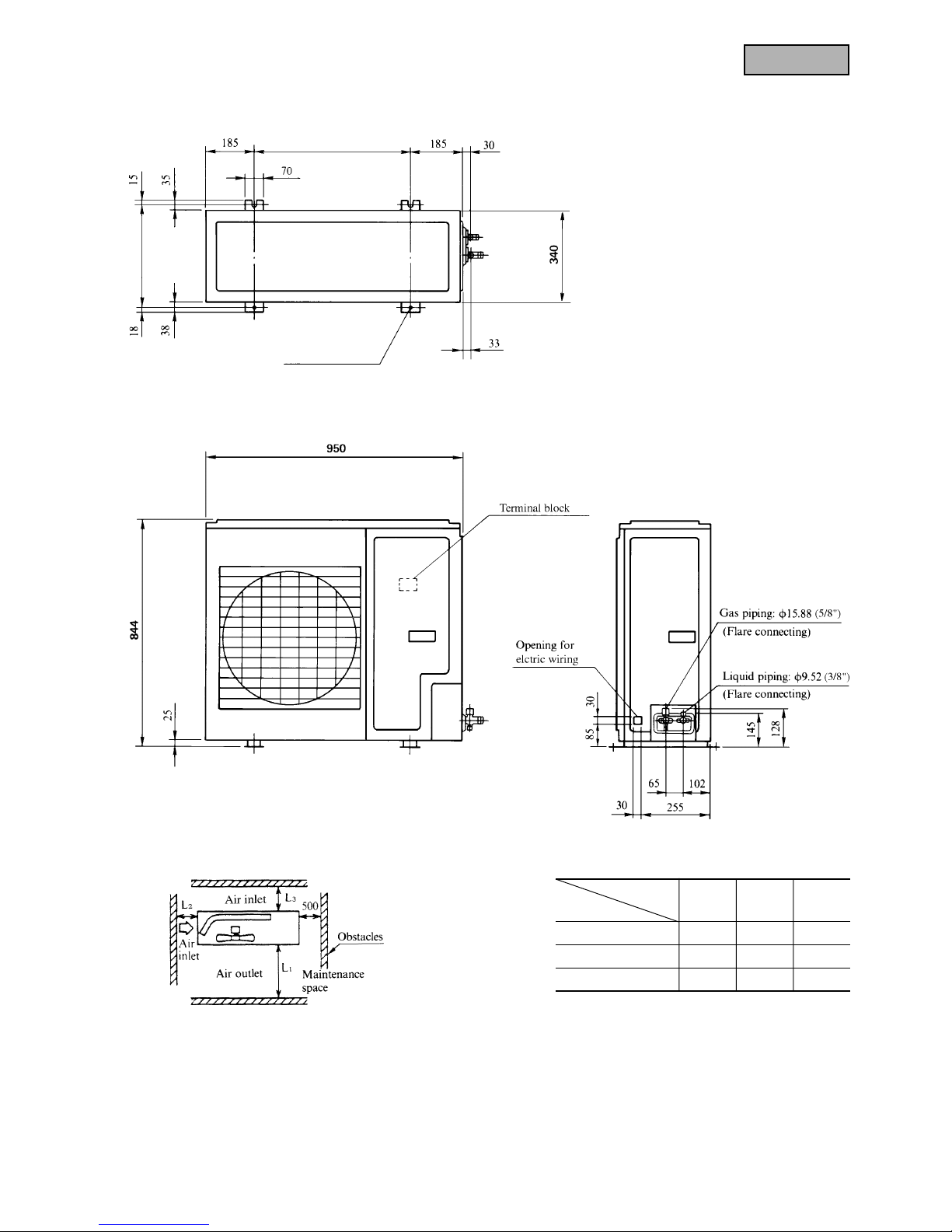
Models FDTN208~508 (FDC206~506 type)
Item FDT308~508 (FDC306~506 type)
214
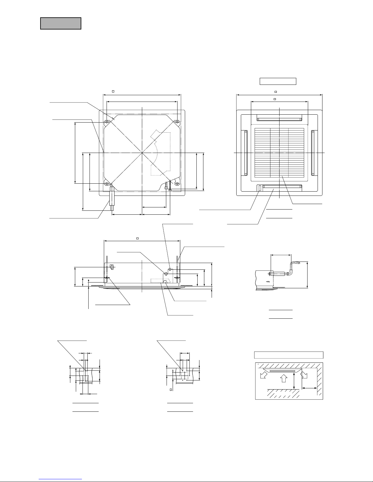
FDTN-H
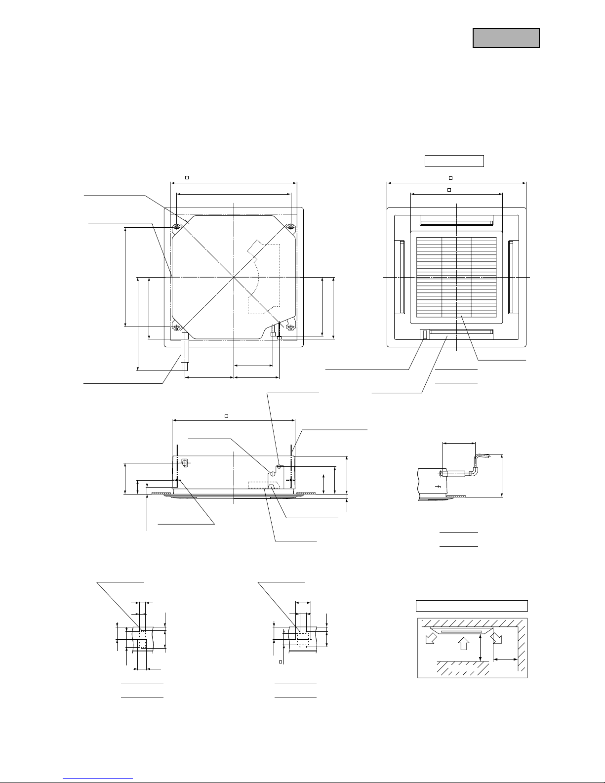
Unit : mm
Decorative Panel
VIEW A
VIEW DVIEW C
VIEW B
Space for installation and service
Liquid piping
φ9.52(3/8")
860~890
(Ceiling hole size)
267
310332
675
(Suspension bolts pitch)
637
422
420
400
780
(Suspension bolts pitch )
Fresh air
opening for ducting
Exhaust air
opening for ducting
Drain hose (Accessories)
(Connectable with VP25)
Gas piping
( φ15.88)
(M10 or M8 ×4pcs.)
B→
C
Air inlet grille
Air outlet grille
630
950
295~325
700
or less
(Max. Drain up)
210
137
187
260
30
45
or more
95
Lug for
suspension bolts
Control box
Hole for wiring
Suspension bolts
A
↑
840
1000
1000
Obstacle
or more
or more
55
25
160 33
80
113
140
Holes for
tapping screws
4-φ4
112
100
60
140
42
140
Holes for
tapping screws
6-φ4
D→
↑
Indication boad
(Only case of FDTN type)
Models FDTN258H, 308H
FDT258, 308
215
FDTN-H
Models FDTN408H, 508H
FDT408, 508
Liquid piping
φ9.52(3/8")
860~890
(Ceiling hole size)
267
310332
675
(Suspension bolts pitch)
637
422
420
400
780
(Suspension bolts pitch )
Fresh air
opening for ducting
Exhaust air
opening for ducting
Drain hose (Accessories)
(Connectable with VP25)
Gas piping
φ19.05(3/4")
(M10 or M8 ×4pcs.)
B→
C
Air inlet grille
Air outlet grille
630
950
295~325
700
or less
(Max. Drain up)
270
137
187
320
30
45
or more
95
Lug for
suspension bolts
Control box
Hole for wiring
Suspension bolts
A
↑
840
1000
1000
Obstacle
or more
or more
55
25
160 93
80
113
140
Holes for
tapping screws
4-φ4
112
100
60
140
42
140
Holes for
tapping screws
6-φ4
D→
↑
Indication board
(Only case of FDTN type)
Unit : mm
Decorative Panel
VIEW A
VIEW DVIEW C
VIEW B
Space for installation and service
216
FDTN-H
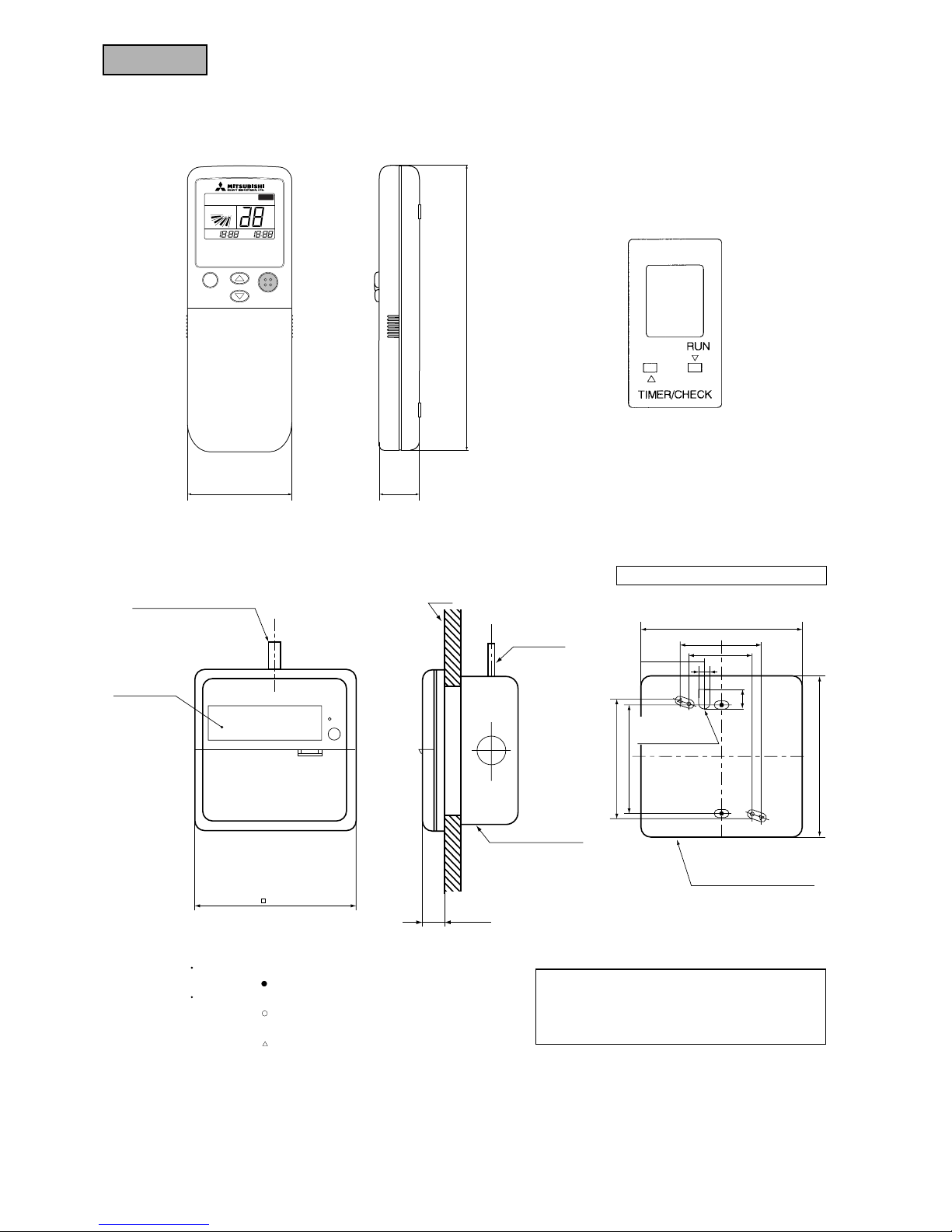
(2) Remote controller
(a) Wireless remote controller
Unit: mm
MODE TEMP ON/OFF
AUTO COOL DRY FAN HEAT
FILTER
°
C
AM
PM
ON
AM
PM
OFF
FAN HI LO
60
20.5
161.5
● Indication board of indoor unit
16
Remote controller mounting dimensions
47
7
Standard Within 0.3 mm
2
× Within 100 m
0.5 mm
2
× Within 200 m
0.75 mm
2
× Within 300 m
1.25 mm
2
× Within 400 m
2 mm
2
× Within 600 m
Allowable rang of wire thickness and length
♦ Usable JIS box, JIS C 8336
⋅ Switch box for 1 piece (without cover)
(use of the mark hole as illustrated on the left)
⋅ Switch box for 2 pieces
(use of the mark hole as illustrated on the left)
(without cover)
(use of the mark hole as illustrated on the left)
(when installing the cover)
Note (1) Allowable length of remote controller cable: 600 m
0.3mm2, 3cores (O.D.φ5.6)
LCD display
120
Wall
Wire
(Recessed)
Junction box
(Locally Purchased)
89
83.5
17
120
Remote controller outline
For the passage
after wiring
120
60
46
(b) Wired remote controller
Unit: mm
218
FDTN-H
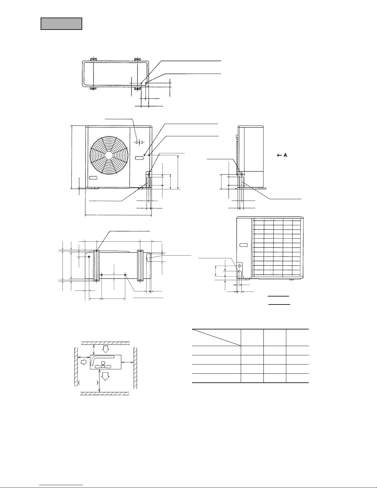
Liquid piping: ø9.52 (3/8")
(Flare connecting)
Gas piping: ø15.88 (5/8")
Terminal block
Opening for
electric wiring
Opening for
electric wiring
Holes for anchor bolt
(M10 × 4 pcs.)
Holes for drain
(ø9.52 × 3pcs.)
Electric wiring
Opening for piping
and electric wiring
Opening for piping
and electric wiring
Opening for piping
and electric wiring
(Flare connecting)
845
10
50
380 1515
340
55
15103
150
7050
47
3535
110
460
110
195
50
195
40
880
310222
40
L
2
L3
L4
L1
Air
inlet
Air inlet
Air outlet
Maintenance
space
150 580 150
50 15
15 50
50
50
5027
50 15
Models FDC258HEN3, 308HEN3, 308HES3
Required space for maintenance and air flow Minimum allowable space to the obstacles
Unit:mm
Mark
123
L1 Open Open 500
L2 300 5 Open
L3 100 150 100
L4 555
Installation
type
Notes
(1) Avoid the location where four sides are entirel y
surrounded by walls.
(2) Fix the unit by anchor bolts without fail. Restrict
the protrusion length of anchor bolt to 15 mm
and under.
(3) When strong wind blows against the unit, direct
the discharge port at a right angle to the wind
direction.
(4) Secure the space of 1 m and over at the top of unit.
(5) Make the height of obstruction wall in front of
discharge port lower than the height of unit.
Unit: mm
VIEW A
Liquid piping: ø9.52 (3/8")
(Flare connecting)
Gas piping: ø15.88 (5/8")
(Flare connecting)
40
53
95
40
219
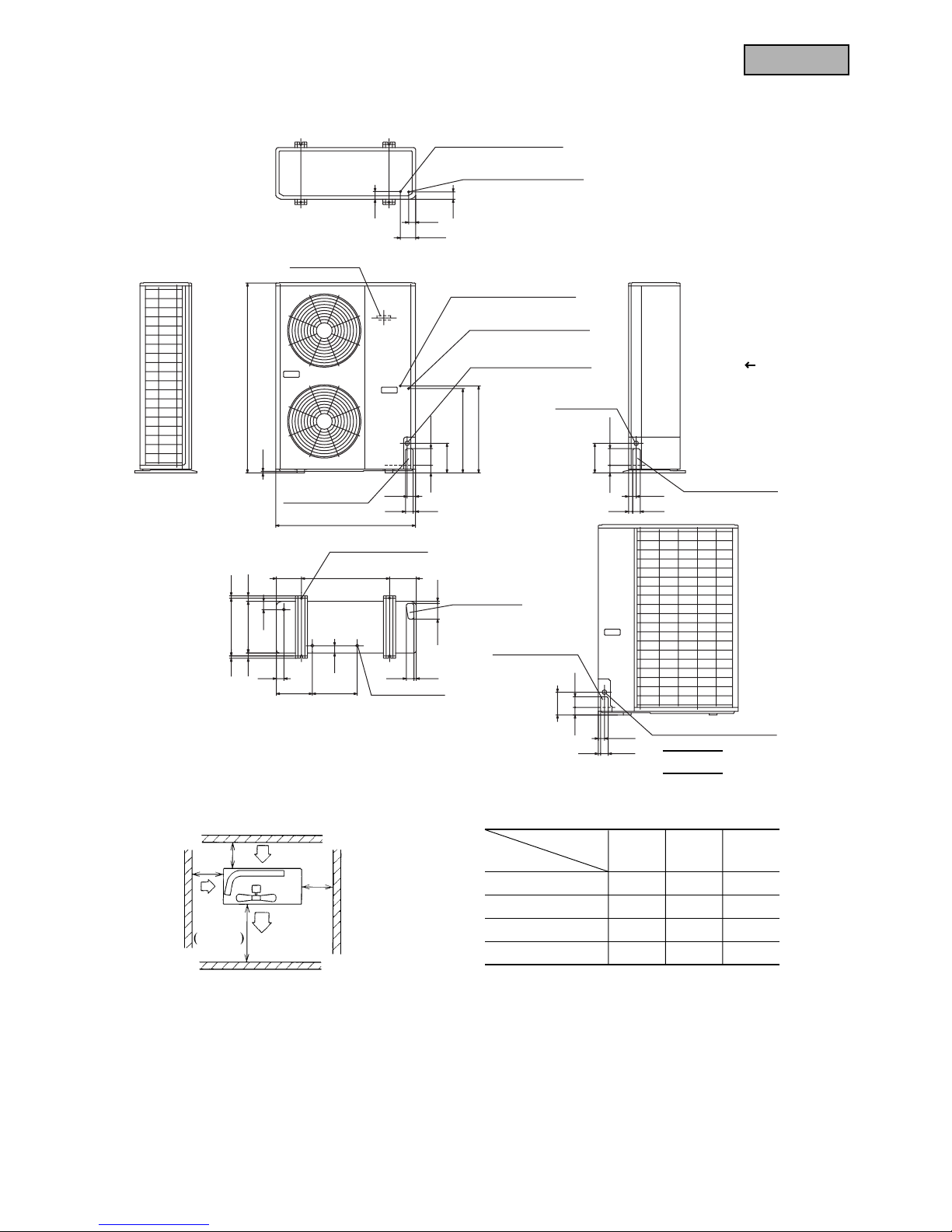
FDTN-H
50
110
195
555
578
920
10
46
50
48
100
165
580
175
35
15
380 15
15
103
5050
50
50 110
195
50
70
50 15
50
27
50
15
47
295237
15
340
35
55
55
150
40
Gas piping: ø 19.05 (3/4")
(Flare connecting)
Liquid piping: ø 9.52 (3/8")
(Flare connecting)
Opening for electric wiring
Holes for drain
(ø 20 × 3pcs.)
Opening for
electric wiring
Opening for piping
and electric wiring
Opening for piping
and electric wiring
Electric wiring
Opening for piping
and electric wiring
Holes for anchor bolt
(M10 × 4pcs.)
Gas piping: ø 19.05 (3/4")
(Flare connecting)
Liquid piping: ø 9.52 (3/8")
(Flare connecting)
Opening for electric wiring
Terminal block
1250 (1050)
A
Note (1) The ( ) value dimension
for model FDC408HES3.
L
2
L
3
L
4
L
1
Air
inlet
Air inlet
Air outlet
Maintenance
space
Models FDC408HES3, 508HES3
Required space for maintenance and air flow Minimum allowable space to the obstacles
Unit:mm
Mark
123
L1 Open Open 500
L2 300 5 Open
L3 150 300 150
L4 555
Installation
type
Notes
(1) Avoid the location where four sides are entirel y
surrounded by walls.
(2) Fix the unit by anchor bolts without fail. Restrict
the protrusion length of anchor bolt to 15 mm
and under.
(3) When strong wind blows against the unit, di-
rect the discharge port at a right angle to the
wind direction.
(4) Secure the space of 1 m and over at the top of unit.
(5) Make the height of obstruction wall in front of
discharge port lower than the height of unit.
VIEW A
Unit: mm
221
FDTN-H
Mark
123
L1 Open Open 500
L2 300 0 Open
L3 100 150 100
Installation
type
Notes
(1) Fix the unit with anchor bolts.
(2) Strong wind must not be directed to the air
outlet.
(3) Free space over the unit must be larger than
1 m.
(4) The unit should not be surrounded by
obstructions in all direction.
At least one direction around the unit must be
free.
Models FDC306HEN3, 306HEP3, 306HES3
Minimum allowable space to the obstacles
Unit:mm
Required space for maintenance and air flow
Unit: mm
Anchor bolts
(M10 × 4 pcs)
580
380
222
FDTN-H
Notes
(1) Fix the unit with anchor bolts.
(2) Strong wind must not be directed to the air
outlet.
(3) Free space over the unit must be larger than
1 m.
(4) The unit should not be surrounded by
obstructions in all direction.
At least one direction around the unit must be
free.
Minimum allowable space to the obstacles
Models FDC406HES3, 506HES3, 506HEM3
Unit:mm
Mark
123
L1 Open Open 500
L2 300 0 Open
L3 150 300 150
Installation
type
Required space for maintenance and air flow
Unit: mm
580
380
223
FDTN-H
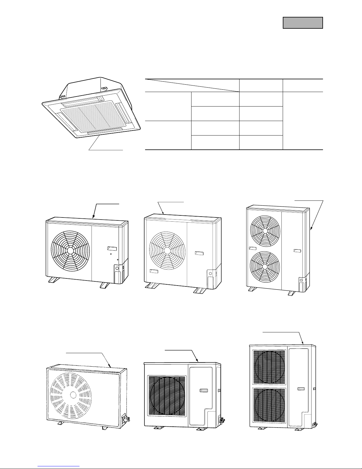
6.2.4 Exterior appearance
(1) Indoor unit
Models All models
(2) Outdoor unit
Model FDC208HEN3
Models FDC306HEN3, 306HEP3,
306HES3
Models FDC406HES3, 506HES3
506HEM3
Pearl white
(Decorative panel)
Polar white
Polar white
Polar white
Polar white
Models FDC258HEN3, 308HEN3,
308HES3
Type
Item
Panel model Remarks
FDTN208H TN-PSC-22W-E
FDTN258H~508H TN-PSC-32W-E
FDT208 T-PSA-22W-E
Without swing
FDT258~508 T-PSA-32W-E
For wireless
remote controller
For wired
remote controller
Models FDC408HES3, 508HES3
Models FDC206HEN3, 206HEP3
256HEN3, 256HEP3
Polar white
Polar white
225
FDTN-H
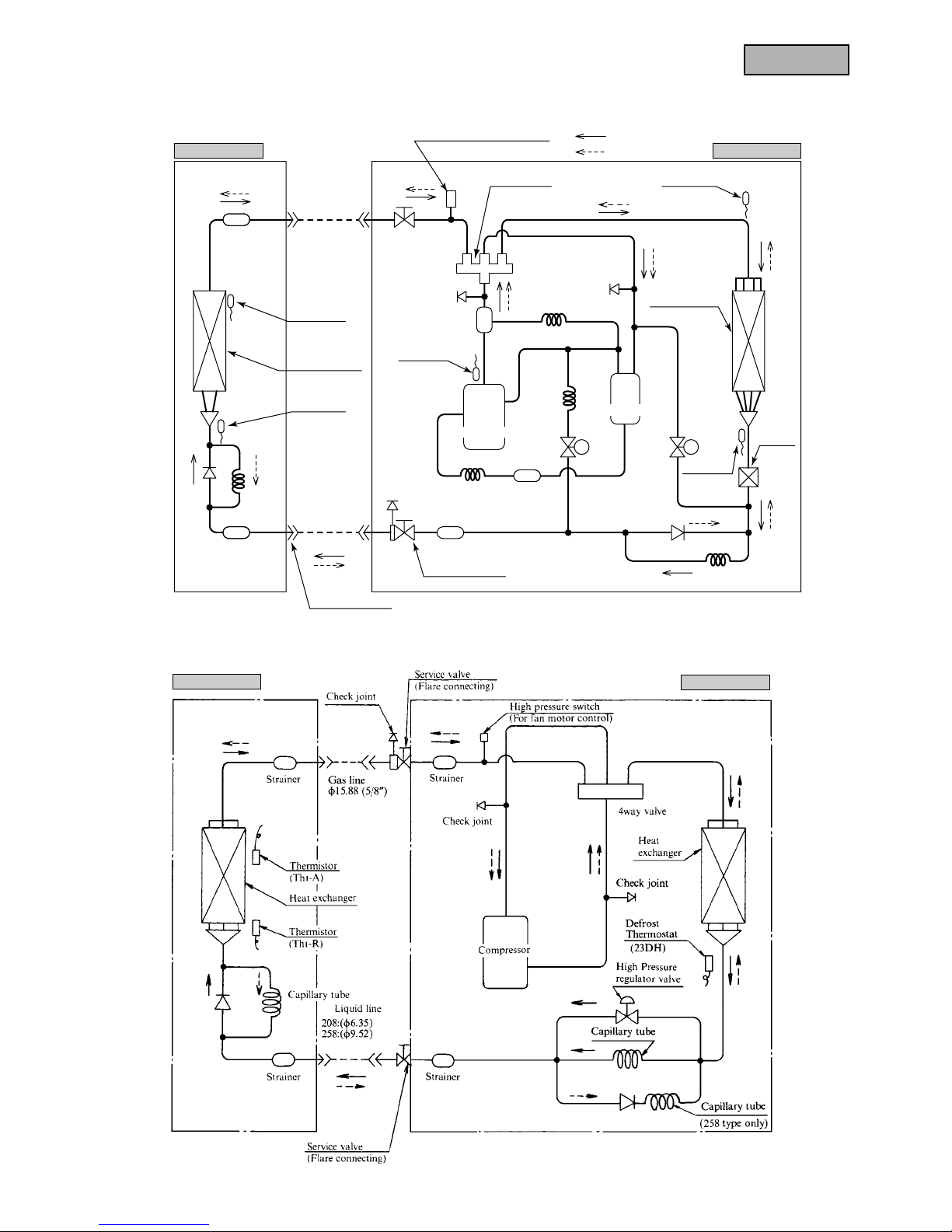
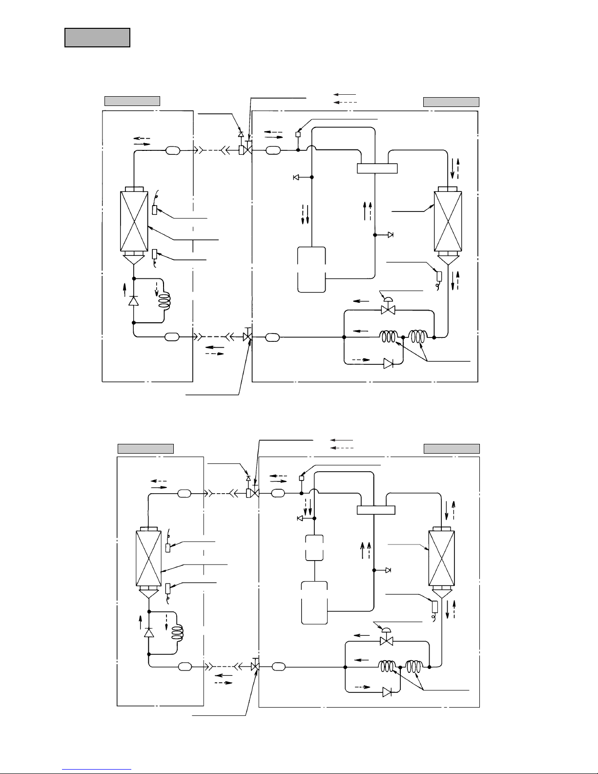
Models FDTN208HEN, 208HEP, 258HEN, 258HEP
Models FDTN508HES-S, FDT508HES-S
Indoor unit
Outdoor unit
Thermistor
(Th
I
-R)
Thermistor
(Th
O
-D)
Thermistor
(Th
O
-R)
Solenoid
valve (SV2)
Solenoid
valve (SV1)
Thermistor
(Th
O
-A)
Thermistor
(Th
I
-A)
Heat exchanger
Heat exchanger
High pressure switch (63H
2
)
(For fan motor control)
Strainer
Strainer Strainer
StrainerCapillary
tube
Capillary tube
Capillary tube
Capillary
tube
Capillary
tube
Liquid line
(ø9.52)
Gas line
(ø19.05)
Flare connecting
Service valve
(Flare connecting)
Service valve
(Flare connecting)
Cooling cycle
Heating cycle
4way valve
Compressor
Accumulators
Check valve
Check
joint
Check joint
Check joint
Oil separator
Subcooling
coil
Indoor unit
Outdoor unit
226
FDTN-H
Thermistor
(Th
I-A)
Heat exchanger
Liquid line
(ø9.52)
Strainer Strainer
Compressor
Accumlator
StrainerStrainer
Thermistor
(Th
I-R)
Service valve
(Flare connecting)
Capillary tube
Capillary tube
High Pressure
regulator valve
Defrost
Thermostat
Check joint
Heat
exchanger
4way valve
High pressure switch
(For fan motor control)
Service valve
(Flare connecting)
Check joint
Check joint
Gas line
(ø19.05)
(23DH)
Thermistor
(Th
I
-A)
Heat exchanger
Liquid line
(ø9.52)
Strainer Strainer
Compressor
StrainerStrainer
Thermistor
(Th
I
-R)
Service valve
(Flare connecting)
Capillary tube
Capillary tube
High Pressure
regulator valve
Defrost
Thermostat
Check joint
Heat
exchanger
4way valve
High pressure switch
(For fan motor control)
Service valve
(Flare connecting)
Check joint
Check joint
Gas line
(ø15.88)
(23DH)
Indoor unit
Outdoor unit
Models FDTN308HEN, 308HEP, 308HES
FDT308HEN, 308HES
Models FDTN408HES, 508HES, 508HEM
FDT408HES, 508HES
Cooling cycle
Heating cycle
Indoor unit
Outdoor unit
Cooling cycle
Heating cycle
227
FDTN-H
Preset point of the protective devices
Parts name Mark
Thermistor
(for protection overloading in heating)
Thermistor
(for frost prevention)
Thermistor
(for detecting discharge pipe temp.)
Thermistor
(for detecting heat
exchange temp.)
High pressure switch
(for controlling FM0)
OFF 68˚C
ON 61˚C
Equipped
unit
ThI-R
Tho-D
Tho-R
63H2
Indoor unit
Outdoor unit
Outdoor unit
Outdoor unit
FDTN308~508
(FDC308~508 type only)
FDT308~508
OFF 2.5˚C
ON 10˚C
OFF 135˚C
ON 90˚C
OFF 70˚C
ON 60˚C
OFF 2.5MPa (25.5 Kgf/cm2G)
ON 2.06MPa (21 kgf/cm2G)
Parts name Mark
Thermistor
(for protection overloading in heating)
Thermistor
(for frost prevention)
Defrost thermostat
High pressure switch
(for controlling FMo)
OFF 68˚C
ON 61˚C
Equipped
unit
THI-R
23DH
2
23DH
1
63H2
Indoor unit
Outdoor unit
Outdoor unit
FDTN208~508
(FDC208, 258 or FDC206~506 type only)
FDT208~508
OFF 2.5˚C
ON 10˚C
OFF 12˚C
ON -6˚C
OFF 2.5MPa (25.5 Kgf/cm2G)
ON 1.86MPa (19 kgf/cm2G)
228
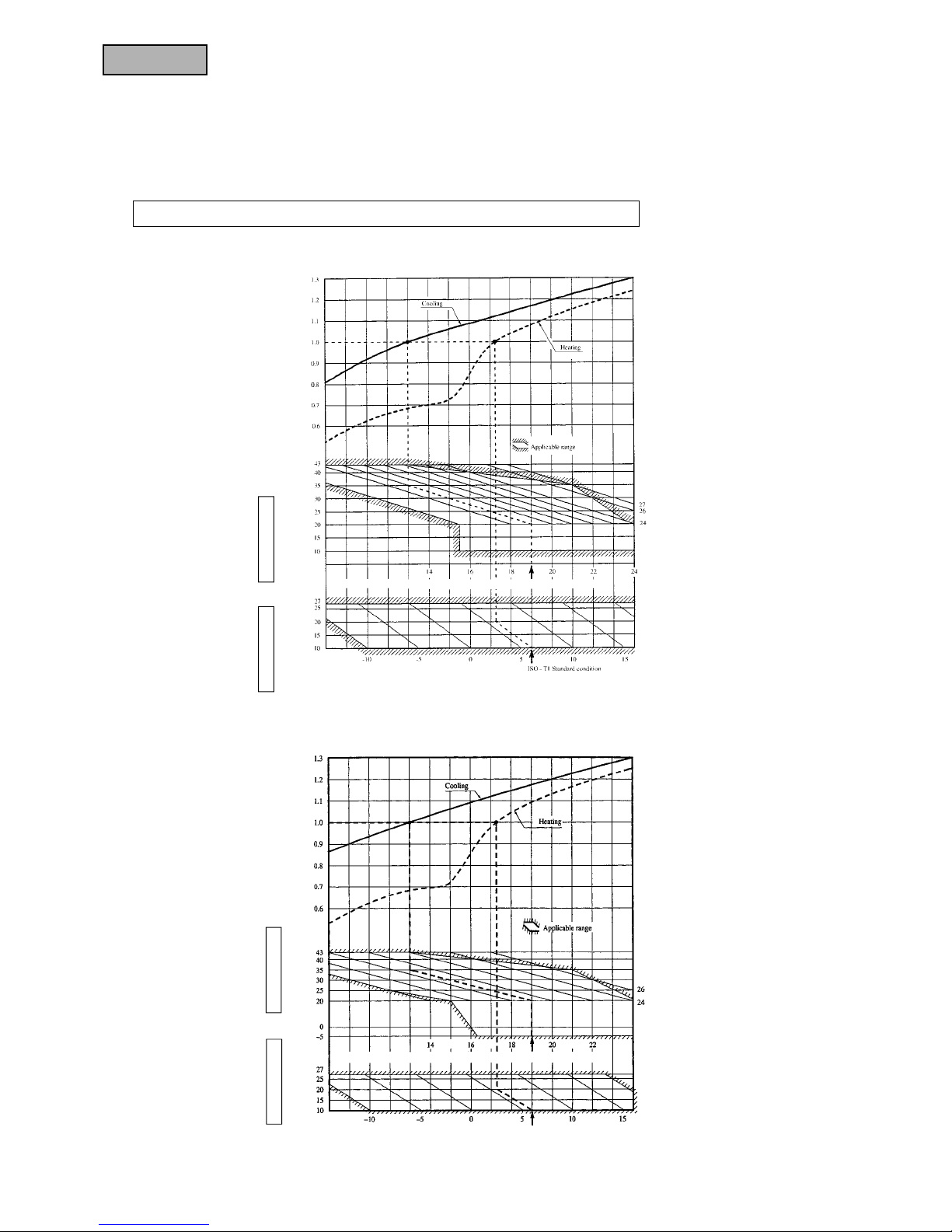
FDTN-H
Outdoor air W.B. temperature (˚CW.B.)
Indoor air W.B. temperature (˚CW.B.)
ISO-T1 Standard condition
(b) Only case of ISO-T1 models (Including 308HEN-S, 308HES-S, 408HES-S, 508HES-S type)
Indoor air W.B. temperature (˚CW.B.)
ISO-T1 Standard condition
Outdoor air D.B.
temperature (˚CD.B.)
Cooling operation
Indoor air D.B.
temperature (˚CD.B.)
Heating operation
Coefficient of cooling and heating capacity
in relation to temperatures
Outdoor air D.B.
temperature (˚CD.B.)
Cooling operation
Indoor air D.B.
temperature (˚CD.B.)
Heating operation
Coefficient of cooling and heating
capacity in relation to temperatures
6.2.6 Selection chart
Correct the cooling and heating capacity in accordance with the conditions as follows. The net cooling and heating capacity can be obtained in
the following way.
Net capacity = Capacity shown on specification × Correction factors as follows.
(1) Coefficient of cooling and heating capacity in relation to temperatures
(a) Only case of ISO-T1 models (Except 308HEN-S, 308HES-S, 408HES-S, 508HES-S type)
ISO-T1 Standard condition
Outdoor air W.B. temperature (˚CW.B.)
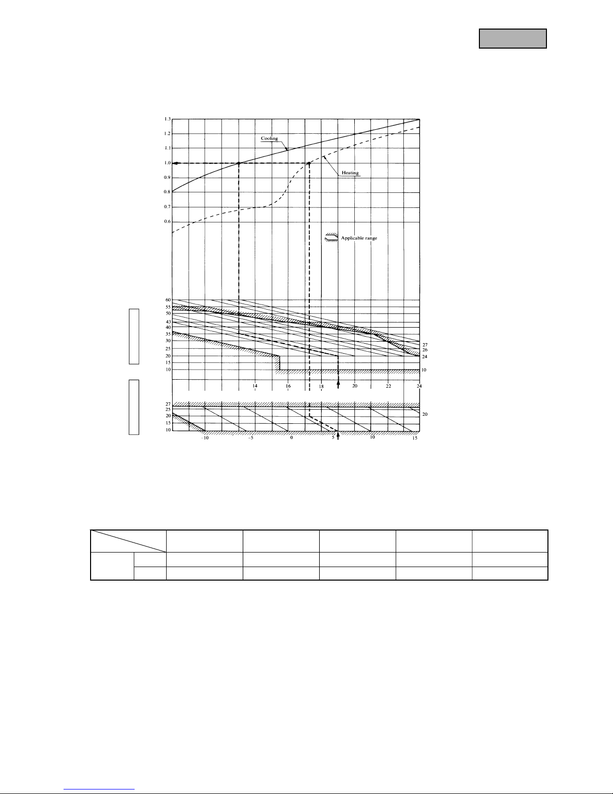
229
FDTN-H
(C) Only case of ISO-T3 and SASO models
Item
Air flow
Hi 0.112 0.050 0.065 0.076 0.025
Lo 0.073 0.030 0.030 0.050 0.013
Model
208 type 258 type 308 type 408 type 508 type
(2) Correction of cooling and heating capacity in relation to air flow rate control (fan speed)
Coefficient: 1.00 at High, 0.95 at Low
Outdoor air W.B. temperature (˚CW.B.)
Table of bypass factor
ISO-T1 Standard condition
Indoor air W.B. temperature (˚CW.B.)
ISO-T1 Standard condition
Outdoor air D.B.
temperature (˚CD.B.)
Cooling operation
Indoor air D.B.
temperature (˚CD.B.)
Heating operation
Coefficient of cooling and heating capacity
in relation to temperatures

230
FDTN-H
Equivalent piping length
(1)
m 5 10152025303540455055
Heating 1.0 1.0 1.0 1.0 1.0 0.995 0.995 0.99 0.99 0.985 0.985
FDTN, FDT208 type 1.0 0.995
FDTN, FDT258 type 1.0 0.995 0.99 0.985 0.98 0.975 0.97
1.0 0.99
0.98 0.97 0.96 0.95 0.94 0.93 0.92 0.91 0.9
1.0
0.995 0.985 0.98 0.97 0.965 0.955 0.95 0.94 0.935 0.925
1.0
0.99 0.975 0.965 0.95 0.94 0.925 0.915 0.9 0.89 0.875
1.0 0.99
1.0
1.0
(3) Correction of cooling and heating capacity in relation to one way length of refrigerant piping
It is necessary to correct the cooling and heating capacity in relation to the one way equivalent piping length between the indoor
and outdoor units.
Note (1) Equivalent piping length can be obtained by calculating as follows.
208, 258, 308 series [φ15.88(5/8″)]: Equivalent piping length = Real piping length + (0.10 × Number or bends in piping)
408, 508, series [φ19.05(3/4″)]: Equivalent piping length = Real piping length + (0.15 × Number of bends in piping)
[Equivalent piping length < Limitation length of piping + 5m]
(4) When the outdoor unit is located at a lower height than the indoor unit in cooling operation and when the outdoor unit is
located at a higher height than the indoor unit in heating operation, the following values should be subtracted from the values in
the above table.
50/60Hz
Height difference between the indoor unit and
outdoor unit in the vertical height difference
5m 10m 15m 20m 25m 30m
Adjustment coefficient 0.01 0.02 0.03 0.04 0.05 0.06
Piping length limitations
Item
Model FDTN, FDT208, 258 FDTN, FDT308~508 FDTN, FDT208~508
Max. one way piping length 30m 50m 30m
Max. vertical height difference
Outdoor unit is higher 20m Outdoor unit is higher 30m
15m
Outdoor unit is lower 15m Outdoor unit is lower 15m
Note (1) Values in the table indicate the one way piping length between the indoor and outdoor units.
How to obtain the cooling and heating capacity
Example : The net cooling capacity of the model FDTN308HEN-S with the air flow “High”, the piping length of 15m, the outdoor unit located
5m lower than the indoor unit, indoor wet-bulb temperature at 19.0 ˚C and outdoor dry-bulb temperature 35 ˚C is
Net cooling capacity = 7100 × 1.00 × (0.98 - 0.01) × 1.0 = 6887 w
Factor by air
temperatures
FDTN308HEN-S Air flow
“High”
Length 15m.
Height difference 5 m
0.995 0.99 0.985 0.985 0.98
/0.99 /0.985 /0.98 /0.975 /0.97
Cooling
FDTN, FDT308 type
(FDC308 type)
FDTN, FDT408 type
(FDC408 type)
FDTN, FDT508 type
(FDC508 type)
FDTN, FDT308 type
(FDC306 type)
FDTN, FDT408 type
(FDC406 type)
FDTN, FDT508 type
(FDC506 type)
0.98 0.97 0.96 0.95 0.94
/0.975 /0.965 /0.95 /0.94 /0.925
0.995 0.985 0.98 0.97 0.965 0.955
/0.99 /0.98 /0.97 /0.96 /0.95 /0.94
0.99 0.975 0.965 0.95 0.94 0.925
/0.985 /0.97 /0.955 /0.94 /0.925 /0.91
(FDC208, 258 type) (FDC308~508 type) (FDC206~506 type)
231
FDTN-H
6.2.7 Noise level
Notes (1) The data are based on the following conditions.
Ambient air temperature:
Indoor unit 27˚C DB, 19˚C WB.
Outdoor unit 35˚C DB.
Indoor unit
Measured based on JIS B 8616
Mike position as below
(2) The data in the chart are measured in an unechonic room.
(3) The noise levels measured in the field are usually higher than the data because of reflection.
(1) Indoor unit
Outdoor unit
Measured based on JIS B 8616
Mike position: at highest noise level
in position as below
Distance from front side 1 m
Height 1 m
Models FDTN208H, FDT208
Noise level 38 dB (A) at HIGH
33 dB (A) at LOW
Models FDTN258H, FDT258
Noise level 39 dB (A) at HIGH
35 dB (A) at LOW
Models FDTN308H, FDT308
Noise level 41 dB (A) at HIGH
35 dB (A) at LOW
Models FDTN408H, FDT408
Noise level 48 dB (A) at HIGH
40 dB (A) at LOW
Models FDTN508H, FDT508
Noise level 49 dB (A) at HIGH
43 dB (A) at LOW
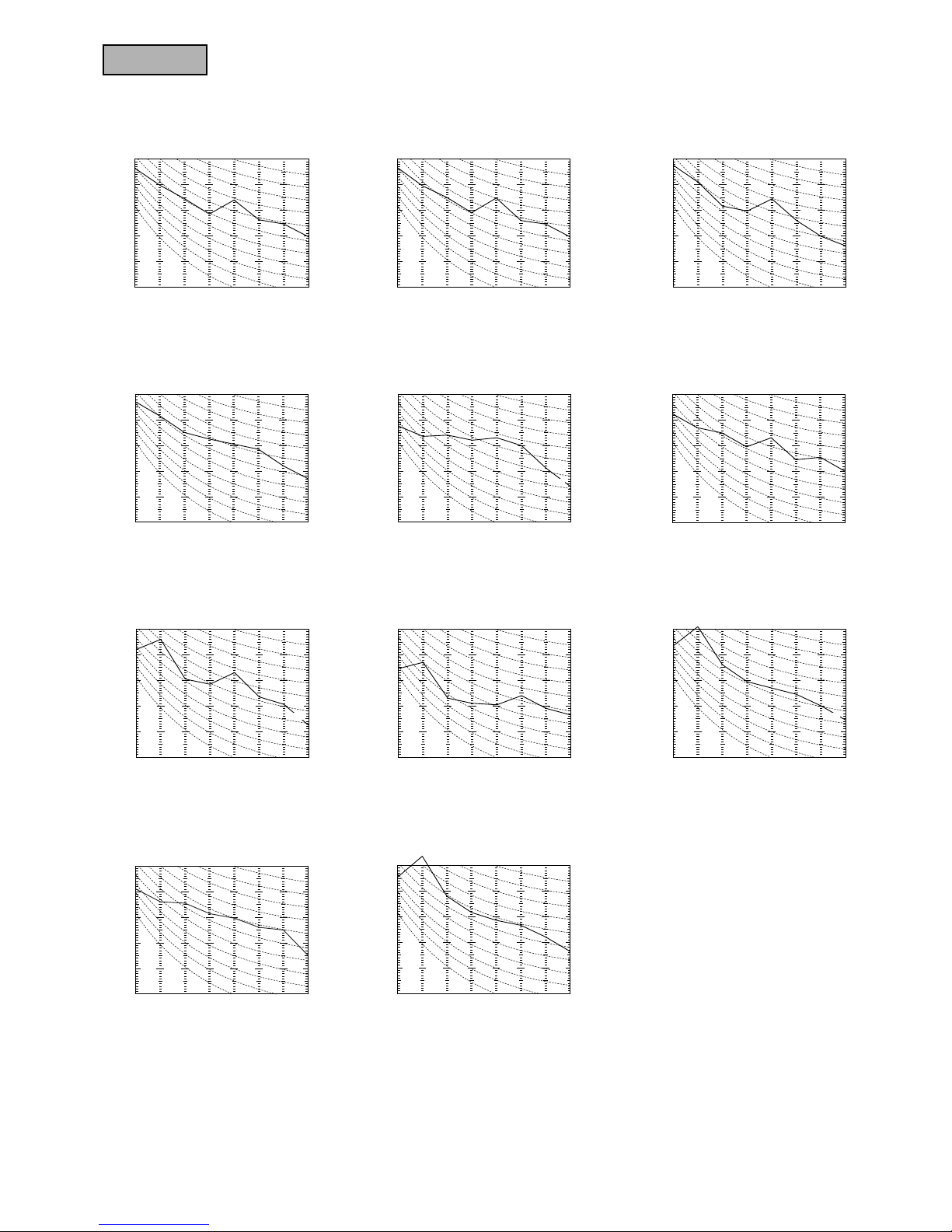
(2) Outdoor unit
Mike (center & low points)
Model FDC206HEN3
Noise level 56 dB (A)
Mid octave band frequency (Hz)
N
30
N20
N
50
N
60
N70
63 125 250 500 1000 2000 4000 8000
20
30
40
50
60
70
20
30
40
50
60
70
N
40
Sound pressure level
(Standard 0.0002µ bar) dB
Mid octave band frequency (Hz)
N
30
N20
N
50
N
60
N
70
63 125 250 500 1000 2000 4000 8000
20
30
40
50
60
70
20
30
40
50
60
70
N40
Sound pressure level
(Standard 0.0002µ bar) dB
Mid octave band frequency (Hz)
N30
N20
N50
N60
N70
63 125 250 500 1000 2000 4000 8000
20
30
40
50
60
70
20
30
40
50
60
70
N40
Sound pressure level
(Standard 0.0002µ bar) dB
Mid octave band frequency (Hz)
N30
N20
N
50
N
60
N
70
63 125 250 500 1000 2000 4000 8000
20
30
40
50
60
70
20
30
40
50
60
70
N
40
Sound pressure level
(Standard 0.0002µ bar) dB
Mid octave band frequency (Hz)
N
30
N20
N
50
N
60
N
70
63 125 250 500 1000 2000 4000 8000
20
30
40
50
60
70
20
30
40
50
60
70
N
40
Sound pressure level
(Standard 0.0002µ bar) dB
Model FDC208HEN3
Noise level 52 dB (A)
Model FDC206HEP3
Noise level 56 dB (A)
Mid octave band frequency (Hz)
N30
N20
N
50
N
60
N70
63 125 250 500 1000 2000 4000 8000
20
30
40
50
60
70
20
30
40
50
60
70
N
40
Sound pressure level
(Standard 0.0002µ bar) dB
Mid octave band frequency (Hz)
N
30
N20
N
50
N
60
N
70
63 125 250 500 1000 2000 4000 8000
20
30
40
50
60
70
20
30
40
50
60
70
N
40
Sound pressure level
(Standard 0.0002µ bar) dB
Mid octave band frequency (Hz)
N30
N20
N50
N60
N
70
63 125 250 500 1000 2000 4000 8000
20
30
40
50
60
70
20
30
40
50
60
70
N40
Sound pressure level
(Standard 0.0002µ bar) dB
232
FDTN-H
Model FDC306HES3
Noise level 56 dB (A)
Model FDC306HEN3
Noise level 56 dB (A)
Souud pressure level
(standard 0.0002µbar)
Mid octave band frequency (Hz)
N
3
0
N20
N
50
N
6
0
N
7
0
63 125 250 500 1000 2000 4000 8000
20
30
40
50
60
70
20
30
40
50
60
70
N
4
0
Model FDC306HEP3
Noise level 56 dB (A)
Mid octave band frequency (Hz)
N
30
N20
N50
N
60
N
70
63 125 250 500 1000 2000 4000 8000
20
30
40
50
60
70
20
30
40
50
60
70
N
40
Sound pressure level
(Standard 0.0002µ bar) dB
Model FDC406HES3
Noise level 57 dB (A)
Model FDC408HES3
Noise level 54 dB (A)
Souud pressure level
(standard 0.0002µbar)
Mid octave band frequency (Hz)
N30
N20
N50
N60
N70
63 125 250 500 1000 2000 4000 8000
20
30
40
50
60
70
20
30
40
50
60
70
N40
Models FDC506HES3, 506HEM3
Noise level 59 dB (A)
Souud pressure level
(standard 0.0002µbar)
Mid octave band frequency (Hz)
N30
N20
N50
N60
N70
63 125 250 500 1000 2000 4000 8000
20
30
40
50
60
70
20
30
40
50
60
70
N40
Model FDC258HEN3
Noise level 52 dB (A)
Mid octave band frequency (Hz)
N
30
N20
N50
N
60
N
70
63 125 250 500 1000 2000 4000 8000
20
30
40
50
60
70
20
30
40
50
60
70
N40
Sound pressure level
(Standard 0.0002µ bar) dB
Souud pressure level
(standard 0.0002µbar)
Mid octave band frequency (Hz)
N30
N20
N50
N60
N70
63 125 250 500 1000 2000 4000 8000
20
30
40
50
60
70
20
30
40
50
60
70
N40
Souud pressure level
(standard 0.0002µbar)
Mid octave band frequency (Hz)
N30
N20
N50
N60
N70
63 125 250 500 1000 2000 4000 8000
20
30
40
50
60
70
20
30
40
50
60
70
N40
Models FDC308HEN3, 308HES3
Noise level 52 dB (A)
Model FDC256HEN3
Noise level 57 dB (A)
Model FDC256HEP3
Noise level 57 dB (A)
Model FDC508HES3
Noise level 55 dB (A)
Mid octave band frequency (Hz)
N
30
N20
N50
N
60
N
70
63 125 250 500 1000 2000 4000 8000
20
30
40
50
60
70
20
30
40
50
60
70
N40
Sound pressure level
(Standard 0.0002µ bar) dB
Mid octave band frequency (Hz)
N
30
N20
N
50
N
60
N
70
63 125 250 500 1000 2000 4000 8000
20
30
40
50
60
70
20
30
40
50
60
70
N4
0
Sound pressure level
(Standard 0.0002µ bar) dB
Souud pressure level
(standard 0.0002µbar)
Mid octave band frequency (Hz)
N
30
N20
N
5
0
N
6
0
N
7
0
63 125 250 500 1000 2000 4000 8000
20
30
40
50
60
70
20
30
40
50
60
70
N
4
0
Souud pressure level
(standard 0.0002µbar)
Mid octave band frequency (Hz)
N
30
N20
N
5
0
N
60
N
7
0
63 125 250 500 1000 2000 4000 8000
20
30
40
50
60
70
20
30
40
50
60
70
N
4
0

234
FDTN-H
TB
Outdoor Unit
RD/WH
BK/WH
BK/RD
BL/WH
BR/WH
Y/GN
BK
DR
DR
Tho-R
63H
2
CnL
LED-R
LED-G
(Check)
(Run)
CnE
Vao
(Checker)
CnA1
Tro
CnA2
BK
Tho-D
BK
Tho-A
6
14V
27
BL/WH
BK/RD
BR/WH
BL
BL
BL
BL
P
P
BR
BR
BK
BK
2625232221201918171613122
31
42
Printed Circuit Board
3
HLUH
A1
CF
01
A2
28
X
05
X
02
X
01
X
03
X
04
X
06
X
08
X
07
X
01
7
PC
PC
CnR
CnM
1
CH
X04X
07
X02X05X
08
X03X
06
1
2/N
345
F(3.15A)
OR/WH
OR/WH
OR
OR
WH
BR
BL
BK
WH
WH
RD
BL
Y/GN
WH
RD
RD
BK/WH
WH
CT1
R
S
C
52C
Cc
RD/WH
RD
BK/WH
N
L
TB
SV
2
SV
1
52C20S
FM
O1
(49FO1)
CM
220/240V
LM
FM
I
(49F
I
)
DM
Y / GN
RD
WH
BK
TB
1
2
3
1
2
9
X
1
X
3
X
4
X
7
X
5
X
2
WH
WH
WH
OR OR
RD
RD
BL
BK
BL
BK
WH
WH
Y / GN
CnJ
CnF
1
CF
I
3
87
6
5
L
H
UH
OR
WHWH
RDWH
RD
BR
BR
GR
CnF
1
CnJ
CnR
CnI
CnI
CnR
4
13
X
1
X2X
3
X
4
X
7
X
5
Val
CnTCnHCnNCnLCnV
CnB
2
CnB
CnA
CnN
CnH
2
ThI–A
ThI–R
BK
BK
BK BK
RD
RD
BK
BK
BK
RDBKBR
CnW
1
CnW
2
CnQ
TrI
Test
XR1
XR2
XR3
XR4
XR5
Option
Receiver amp
Wireless
remote
controller
LED1
LED2
SW
( 3 )
( 3 )
( 3 )
SW2
SW3
ONONOFF
OFF
1 2 3 4
1 2 3 4
PC
FS
Indoor Unit
X
6
4
5
BL
BR
PC
10
14
X
6
220/240V
12V
CnSCnB
Remote
controller
BKBKRDWHBK
RD WH BK
Thc
BK LS
CnS2
BK
Only case of FDT series.
1
YYZZX
X
1
Printed wiring board
Power source
1 Phase 220/240V 50Hz
Models FDTN308HEN-S
FDT308HEN-S
Color mark
Mark Color
BK Black
BL Blue
BR Brown
GR Gray
OR Orange
PK Pink
RD Red
WH White
Y Yellow
Mark Color
BK/RD Black/Red
BK/WH Black/White
BL/WH Blue/White
BR/WH Brown/White
OR/WH Orange/White
RD/WH Red/White
Y/GN Yellow/Green
]
This diagram indicates the FDTN series. Section from
1 changes on
the FDT series.
[
Meaning of marks
Mark Parts name Mark Parts name
CC Capacitor for CM Th
C
Thermistor
CF
I Capacitor for FM
I
ThI-A Thermistor
CF
O Capacitor for FM
O
ThI-R Thermistor
CH Crankcase heater Tho-A Thermistor
CM Compressor motor Tho-D Thermistor
CnA ~ W Connector (□ mark) Tho-R Thermistor
CT
1 Current sensor Tr
I
Transformer (Indoor unit)
F Fuse Tr
O
Transformer (Outdoor unit)
FM
I Fan motor (Indoor unit) Val VaristorFMO Fan motor (Outdoor unit) Vao Varistor
LED1 Indication lamp (Green - Run) 20S 4-way valve solenoid
LED2 Indication lamp
(Yellow - Timer/Check)
49FI
Internal thermostat for FM
I
LM Louver motor 49F
O
Internal thermostat for FMo
LS Limit switch 52C Magnetic contactor for CM
PC Photo coupler X1~7 Auxiliary relay
SV
1,2 Solenoid coil (for control) X01~8 Auxiliary relay
SW Switch (ON/OFF) 63H
2
High pressure switch (for control)
SW2, 3 Changeover switch v Terminal (F)
TB Terminal block (嘷 mark) ■ Connector
DM Drain motor LED-G Indication lamp (Green)
FS Float switch LED-R Indication lamp (Red)

235
FDTN-H
Power source
3 Phase 380/415V 50Hz
Indoor Unit
TB
Outdoor Unit
RD/WH
BK/WH
BK/RD
BL/WH
BR/WH
Y/GN
BK
DR
DR
Tho-R
63H
2
CnL
LED-R
LED-G
(Check)
(Run)
CnE
Vao
(Checker)
CnA1
Tro
CnA2
BK
Tho-D
BK
Tho-A
6
14V
27
BL/WH
BK/RD
BR/WH
BL
BL
BL
BL
P
P
BR
BR
BK
BK
26252322212019181716131221
13
24
5
6
Printed Circuit Board
3
HL
UH
A1
CF
01
A2
28
X
05
X
02
X
01
X
03
X
04
X
06
X
08
X
07
X
01
220/240V
7
PC
PC
CnR
CnM
1
CH
X04X
07
X02X05X
08
X
03X06
1
2/N
345
F(3.15A)
OR/WH
OR/WH
OR
OR
WH
BR
BL
BK
BL
RD
Y/GN
WH
WH
BL
RDWHBL
BK/WH
RD
CT2CT1
V
UW
52C
RD/WH
RD
BK/WH
WH
L3L
1
N
L
2
TB
SV
2
SV
1
52C
20S
FM
O1
(49F
O1
)
CM
LM
FM
I
(49F
I
)
DM
Y/GN
RD
WH
BK
TB
1
2
9
X
1
X
3
X
4
X
7
X
5
X
2
WH
WH
WH
OR
OR
RD
RD
BL
BK
BL
BK
WH
WH
Y/GN
CnJ
CnF
1
CF
I
3
87
6
5
L
H
UH
OR
WHWH
RDWH
RD
BR
BR
GR
CnF
1
CnJ
CnR
CnI
CnI
CnR
4
13
X
1
X2X
3
X
4
X
7
X
5
Val
CnT
CnH
CnN
CnL
CnV
CnB
2
CnB
CnA
CnN
CnH
2
ThI–A
ThI–R
BK
BK
BK BK
RD
RD
BK
BK
BK
RDBKBR
CnW
1
CnW
2
CnQ
TrI
Test
XR1
XR2
XR3
XR4
XR5
Option
Receiver amp
Wireless
remote
controller
LED1
LED2
SW
( 3 )
( 3 )
( 3 )
SW2
SW3
ONONOFF
OFF
1 2 3 4
1 2 3 4
PC
FS
X
6
BL
BR
PC
10
14
X
6
220/240V
12V
1
2/N
345
CnSCnB
Remote
controller
BKBKRDWHBK
RD WH BK
Thc
BK LS
CnS2
BK
Only case of FDT series.
1
1
YYZZX
X
Printed wiring board
Models FDTN308HES-S
FDT308HES-S
Color mark
Mark Color
BK Black
BL Blue
BR Brown
GR Gray
OR Orange
P Pink
RD Red
WH White
Mark Color
BK/RD Black/Red
BK/WH Black/White
BL/WH Blue/White
BR/WH Brown/White
OR/WH Orange/White
RD/WH Red/White
Y/GN Yellow/Green
]
This diagram indicates the FDTN series. Section from
1 changes on
the FDT series.
[
Meaning of marks
Mark Parts name Mark Parts name
CF
I
Capacitor for FMI
ThI
-R Thermistor
CF
O1
Capacitor for FMO
Tho-A Thermistor
CH Crankcase heater Tho-D Thermistor
CM Compressor motor Tho-R Thermistor
CnA ~ Z Connector (□ mark) TrI
Transformer (Indoor unit)
CT
1,2
Current sensor Tr
O
Transformer (Outdoor unit)
F Fuse Val Varistor
FM
I
Fan motor (Indoor unit) Vao Varistor
FM
O1
Fan motor (Outdoor unit) 20S 4-way valve solenoid
LM
Louver motor
49F
I Internal thermostat for FM
I
LS Limit switch 49F
O1 Internal thermostat for FMo
DM Drain motor 52C Magnetic contactor for CM
FS Float switch X1~7 Auxiliary relay
PC Photo coupler X
01~08
Auxiliary relay
SV
1,2
Solenoid coil (for control) 63H
2 High pressure switch (for control)
SW Switch (ON/OFF) v Terminal (F)
SW2, 3 Changeover switch ■ Connector
TB Terminal block (嘷 mark) LED-G Indication lamp (Green)
Thc Thermistor LED-R Indication lamp (Red)
ThI-A Thermistor

236
FDTN-H
Indoor Unit
TB
Outdoor Unit
RD/WH
BK/WH
BK/RD
BL/WH
BR/WH
Y/GN
BK
DR
DR
Tho-R
63H
2
CnL
LED-R
LED-G
(Check)
(Run)
CnE
Vao
(Checker)
CnA1
Tro
CnA2
BK
Tho-D
BK
Tho-A
6
14V
27
BL/WH
BK/RD
BR/WH
BL
BL
BL
BL
P
P
BR
BR
BK
BK
26252322212019181716131221
13
24
5
6
Printed Circuit Board
3
HL
UH
A1
CF
01
A2
28
X
05
X
02
X
01
X
03
X
04
X
06
X
08
X
07
X
01
220/240V
7
PC
PC
CnR
CnM
1
CH
X04X
07
X
02
X05X
08
X
03
X
06
1
2/N
345
F(3.15A)
OR/WH
OR/WH
OR
OR
WH
BR
BL
BK
BL
RD
Y/GN
WH
WH
BL
RDWHBL
BK/WH
RD
CT2CT1
V
UW
52C
RD/WH
RD
BK/WH
WH
L3L
1
N
L
2
TB
SV
2
SV
1
52C20S
FM
O1
(49F
O1
)
1514
HL
UH
CF
02
CnM2
GR
GR
OR
OR
WH
BR
BL
BK
FM
O2
(49F
O2
)
CM
LM
FMI
(49F
I
)
DM
Y/GN
RD
WH
BK
TB
1
2
9
X1
X3
X4
X7
X5
X2
WH
WH
WH
OR
OR
RD
RD
BL
BK
BL
BK
WH
WH
Y/GN
CnJ
CnF1
CFI
3
87
6
5
L
H
UH
OR
WHWH
RDWH
RD
BR
BR
GR
CnF
1
CnJ
CnR
CnI
CnI
CnR
4
13
X1
X2
X3
X4X7X5
Val
CnT
CnH
CnN
CnL
CnV
CnB2
CnB
CnA
CnN
CnH
2
ThI–A
ThI–R
BK
BK
BK BK
RD
RD
BK
BK
BK
RDBKBR
CnW
1
CnW
2
CnQ
TrI
Test
XR1
XR2
XR3
XR4
XR5
Option
Receiver amp
Wireless
remote
controller
LED1
LED2
SW
( 3 )
( 3 )
( 3 )
SW2
SW3
ONONOFF
OFF
1 2 3 4
1 2 3 4
PC
Printed wiring board
FS
X6
BL
BR
PC
10
14
X6
220/240V
12V
1
2/N
345
1
CnSCnB
Remote
controller
BK
BKRDWH
BK
RD WH BK
Thc
BK LS
CnS2
BK
Only case of FDT series.
1
YYZZX
X
Models FDTN408HES-S, 508HES-S
FDT408HES-S, 508HES-S
Power source
3 Phase 380/415V 50Hz
]
This diagram indicates the FDTN series. Section from
1 changes on
the FDT series.
[
Meaning of marks
Mark Parts name Mark Parts name
CF
I Capacitor for FM
I
ThI-R Thermistor
CF
O1,2 Capacitor for FM
O
Tho-A Thermistor
CH Crankcase heater Tho-D Thermistor
CM Compressor motor Tho-R Thermistor
CnA ~ Z Connector (□ mark) TrI Transformer (Indoor unit)
CT
1,2 Current sensor Tr
O Transformer (Outdoor unit)
F Fuse Val Varistor
FM
I Fan motor (Indoor unit) Vao VaristorFMO1,2 Fan motor (Outdoor unit) 20S 4-way valve solenoid
LM Louver motor 49F
I Internal thermostat for FM
I
LS Limit switch 49F
O1,2 Internal thermostat for FMo
DM Drain motor 52C Magnetic contactor for CM
FS Float switch X1~7 Auxiliary relay
PC Photo coupler X01~08 Auxiliary relay
SV
1,2 Solenoid coil (for control) 63H
2 High pressure switch (for control)
SW Switch (ON/OFF) v Terminal (F)
SW
2,3 Changeover switch ■ Connector
TB Terminal block (嘷 mark) LED-G Indication lamp (Green)
Th
C Thermistor LED-R Indication lamp (Red)
ThI-A Thermistor
Color mark
Mark Color
BK Black
BL Blue
BR Brown
GR Gray
OR Orange
P Pink
RD Red
WH White
Mark Color
BK/RD Black/Red
BK/WH Black/White
BL/WH Blue/White
BR/WH Brown/White
OR/WH Orange/White
RD/WH Red/White
Y/GN Yellow/Green

237
FDTN-H
Models FDTN208HEN, 208HEP, 258HEN, 258HEP, 308HEN, 308HEP
FDT308HEN
Meaning of marks
Mark Parts name Mark Parts name
CC Capacitor for CM Th
C
Thermistor
CF
I
Capacitor for FMI
ThI-A Thermistor
CF
O
Capacitor for FMO
ThI-R Thermistor
CH Crankcase heater TrI Transformer
CM Compressor motor Val Varistor
CnA ~ W Connector (□ mark) 20S 4-way valve solenoid
DM Drain motor 23DH Thermostat (deicer)
F Fuse 49C Internal thermostat for CM
FM
I
Fan motor (Indoor unit) 49F
I Internal thermostat for FM
I
FMO
Fan motor (Outdoor unit) 49F
O Internal thermostat for FMo
FS Float switch 52C Magnetic contactor for CM
LED1 Indication lamp (Green - Run) 52F
O Relay for FM
O
LED2 Indication lamp (
Yellow - Timer/Check
) 52X
O Relay for fan control
LM Louver motor X1~7 Auxiliary relay
LS Limit switch 63H
2 High pressure switch (for control)
NR Surge suppressor v Terminal (F)
PC Photo coupler ■ Connector
SW Switch (ON/OFF)
SW2, 3 Changeover switch
TB Terminal block (嘷 mark)
L
N
CM
FM0
(49F0)
52C
LM
FMI
(49FI)
DM
TB
RD
WH
WH
WH
WH
RD
RD
BL
BK
BK
1
35
2
4
6
WH
WH
CC
RD
BK
R
S
C
Y / GN
OR
OR
OR OR
CnM
CnM
CF
O
CnP
CnM
CnP
BK
BK
WH
RD
F(3 . 15A)
RD
RD
TB
WH
BK
WH
Y / GN
A
B
Y / GN
RD
WH
BK
TB
1
2
3
1
2
3
1
2
9
X1
X3
X4
X7
X5
X2
WH
WH
WH
OR OR
RD
RD
BL
BK
BL
BK
WH
WH
Y / GN
CnJ
CnF
1
CFI
3
87
6
5
L
H
UH
OR
WHWH
RDWH
RD
BR
BR
GR
CnF1
CnJ
CnR
CnI
CnI
CnR
4
13
X
1
X2
X3
X4X7X5
Val
CnT
CnH
CnN
CnL
CnV
CnB2
CnB
CnA
CnN
CnH
2
ThI–A
ThI–R
BK
BK
BK BK
RD
RD
BK
BK
BK
RDBKBR
CnW
1
CnW2
CnQ
TrI
Test
XR1
XR2
XR3
XR4
XR5
Option
Receiver amp
Wireless
remote
controller
LED1
LED2
SW
( 3 )
( 3 )
( 3 )
SW2
SW3
ONONOFF
OFF
1 2 3 4
1 2 3 4
PC
52C
CH
FS
Outdoor Unit
Indoor Unit
52C
52XO
6
4
7
8
7
8
BK
BL
CnD
52Xo
52Fo
20S
BL
BR
BK
BL
BK
63H2
5
3
OR
52Xo
5
OR
WH
4
5
BL
BR
BR
X6
4
5
BL
BR
PC
10
14
1
52F
O
1
23DH1
CnD
WH
WH
WH
WH
CnD
BK
CnD
23DH
2
X6
BK
BK
BRBR
Y / GN
Y / GN
(49C)
NR
BK
220/240V
12V
CnM
BK
BK
BK
BK
CnSCnB
Remote
controller
BKBKRDWHBK
RD WH BK
Thc
BK LS
CnS2
BK
Only case of FDT series.
1
1
YYZZX
X
Printed wiring board
]
This diagram indicates the FDTN series. Section from
1 changes on
the FDT series.
[
Color mark
Mark Color
BK Black
BL Blue
BR Brown
GR Gray
OR Orange
RD Red
WH White
Y/GN Yellow/Green
Power source
FDTN208HEN, 258HEN, 308HEN, FDT308HEN
1 Phase 220/240V 50Hz
FDTN208HEP, 258HEP, 308HEP
1 Phase 220V 60Hz

238
FDTN-H
Models FDTN308HES
FDT308HES
L1
L2
CM
FMO
(49FO)
52C
LM
FMI
(49FI)
DM
TB
RD
WH
WH
WH
RD
BL
BL
BK
1
3
5
2
46
WH
WH
BK
Y / GN
OR
OR
OR OR
CnM
CnM
CF
O
CnM
F(3 . 15A)
RD
TB
BK
BK
BK
Y / GN
A
B
Y / GN
RD
WH
BK
TB
1
2
3
1
2
3
1
2
9
X
1
X3
X4
X7
X5
X2
WH
WH
WH
O R O R
RD
RD
BL
BK
BL
BK
WH
WH
Y / GN
CnJ
CnF
1
CFI
3
87
6
5
L
H
UH
OR
WHWH
RDWH
RD
BR
BR
GR
CnF1
CnJ
CnR
CnI
CnI
CnR
4
13
X1
X2
X3
X4
X7
X5
Val
CnT
CnH
CnN
CnL
CnV
CnB2
CnB
CnA
CnN
CnH
2
ThI–A
ThI–R
BK
BK
BK BK
RD
RD
BK
BK
BK
RDBKBR
CnW
1
CnW2
CnQ
TrI
Test
XR1
XR2
XR3
XR4
XR5
Option
Receiver amp
Wireless
remote
controller
LED1
LED2
SW
( 3 )
( 3 )
( 3 )
SW2
SW3
ONONOFF
OFF
1 2 3 4
1 2 3 4
PC
52C
FS
NR
RD
Y / GN
Y / GN
WH
BK
N
L3
BL
BK
CnM
(49C)
T1
T2
T3
Outdoor Unit
Indoor Unit
CnP
CnP
BK
BK
52C
CH
WH
BK
63H2
5
3
OR
52Xo
1
5
OR
WH
1
52FO
52XO
6
4
7
8
7
8
BL
CnD
52Xo
52Fo
20S
BR
BL
BL
BR
BR
23DH1
CnD
WH
WH
WH
CnD
BK
CnD
23DH
2
BK
BK
BK
BRBR
X6
PC
BK
220/240V
12V
BK
RD RD
BK
BK
BK
4
5
4
5
BL
BL
BR
10
14
X6
CnSCnB
Remote
controller
BKBKRDWHBK
RD WH BK
Thc
BK LS
CnS2
BK
Only case of FDT series.
1
1
YYZZX
X
Printed wiring board
]
This diagram indicates the FDTN series. Section from
1 changes on
the FDT series.
[
Power Source
3 Phase 380-415V 50Hz / 380V 60Hz
Color mark
Mark Color
BK Black
BL Blue
BR Brown
GR Gray
OR Orange
RD Red
WH White
Y/GN Yellow/Green
Meaning of marks
Mark Parts name Mark Parts name
CF
I Capacitor for FM
I
ThC Thermistor
CF
O Capacitor for FM
O
ThI-A Thermistor
CH Crankcase heater Th
I-R Thermistor
CM Compressor motor TrI Transformer
CnA ~ W Connector (□ mark) Val Varistor
DM Drain motor 20S 4-way valve solenoid
F Fuse 23DH Thermostat (deicer)
FM
I Fan motor (Indoor unit) 49C Internal thermostat for CM
FM
O Fan motor (Outdoor unit) 49F
I Internal thermostat for FM
I
FS Float switch 49F
O Internal thermostat for FMo
LED1 Indication lamp (Green - Run) 52C Magnetic contactor for CM
LED2 Indication lamp (
Yellow - Timer/Check
) 52FO Relay for FM
O
LM Louver motor 52X
O Relay for fan control
LS Limit switch X1~7 Auxiliary relay
NR Surge suppressor 63H
2 High pressure switch (for control)
PC Photo coupler v Terminal (F)
SW Switch (ON/OFF) ■ Connector
SW2, 3 Changeover switch
TB Terminal block (嘷 mark)

239
FDTN-H
Models FDTN408HES, 508HES
FDT408HES, 508HES
L
1
L
2
CM
FMO1
(49FO1)
52C
LM
FMI
(49FI)
DM
TB
RD
WH
WH
WH
RD
BL
BL
BK
1
3
5
2
46
WH
WH
BK
Y / GN
OR
OR
OR OR
CnM
CnM
1
CFOI
CnM1
F(3 . 15A)
RD
TB
BK
BK
BK
Y / GN
A
B
Y / GN
RD
WH
BK
TB
1
2
3
1
2
3
1
2
9
X1
X3
X4
X7
X5
X2
WH
WH
WH
OR OR
RD
RD
BL
BK
BL
BK
WH
WH
Y / GN
CnJ
CnF
1
CFI
3
87
6
5
L
H
UH
OR
WHWH
RDWH
RD
BR
BR
GR
CnF1
CnJ
CnR
CnI
CnI
CnR
4
13
X
1
X2X
3
X
4
X
7
X
5
Val
CnT
CnH
CnN
CnL
CnV
CnB2
CnB
CnA
CnN
CnH
2
ThI–A
ThI–R
BK
BK
BK BK
RD
RD
BK
BK
BK
RDBKBR
CnW
1
CnW
2
CnQ
TrI
Test
XR1
XR2
XR3
XR4
XR5
Option
Receiver amp
Wireless
remote
controller
LED1
LED2
SW
( 3 )
( 3 )
( 3 )
SW2
SW3
ONONOFF
OFF
1 2 3 4
1 2 3 4
PC
52C
FS
NR
RD
Y / GN
Y / GN
BK
N
L
3
BL
BK
CnM
1
(49C)
T1
T2
T3
Outdoor Unit
Indoor Unit
CnP
CnP
BK
BK
52C
CH
WH
63H
2
5
3
OR
52Xo
1
5
OR
WH
1
52FO
BK
52XO
6
4
7
8
7
8
BL
CnD
52Xo
52Fo
20S
BR
BL
BL
BR
BR
23DH1
CnD
WH
WHWH
CnD
BK
CnD
23DH
2
BK
BK
BK
BRBR
X6
PC
BK
FMO2
(49FO2)
WH
WH
BK
OR
OR
OR OR
CnM
CnM
2
CFO2
CnM
2
Y / GN
CnM
2
220/240V
12V
BK
BK
WH
BK
BK
BK
RDRD
RD
4
5
4
5
BL BL
BR
10
14
X
6
BK
BK
CnSCnB
Remote
controller
BK
BKRDWH
BK
RD WH BK
Thc
BK LS
CnS2
BK
Only case of FDT series.
1
1
YYZ
Z
X
X
Printed wiring board
Meaning of marks
Mark Parts name Mark Parts name
CF
I
Capacitor for FMI
ThC
Thermistor
CF
O1,2
Capacitor for FMO
ThI-A Thermistor
CH Crankcase heater Th
I-R Thermistor
CM Compressor motor TrI Transformer
CnA ~ W Connector (□ mark) Val Varistor
DM Drain motor 20S 4-way valve solenoid
F Fuse 23DH Thermostat (deicer)
FM
I
Fan motor (Indoor unit) 49C Internal thermostat for CM
FM
O1,2
Fan motor (Outdoor unit) 49F
I
Internal thermostat for FM
I
FS Float switch 49F
O1,2
Internal thermostat for FMo
LED1 Indication lamp (Green - Run) 52C Magnetic contactor for CM
LED2 Indication lamp (
Yellow - Timer/Check
) 52FO
Relay for FMO
LM Louver motor 52X
O
Relay for fan control
LS Limit switch X1~7 Auxiliary relay
NR Surge suppressor 63H
2
High pressure switch (for control)
PC Photo coupler v Terminal (F)
SW Switch (ON/OFF) ■ Connector
SW2, 3 Changeover switch
TB Terminal block (嘷 mark)
]
This diagram indicates the FDTN series. Section from
1 changes on
the FDT series.
[
Power Source
3 Phase 380-415V 50Hz / 380V 60Hz
Color mark
Mark Color
BK Black
BL Blue
BR Brown
GR Gray
OR Orange
RD Red
WH White
Y/GN Yellow/Green

240
FDTN-H
Model FDTN508HEM
R
S
CM
FM
O1
(49F
O1
)
52C
LM
FM
I
(49F
I
)
DM
TB
RD
WH
WH
WH
RD
BL
BL
BK
1
3
5
2
46
WH
WH
BK
Y / GN
OR
OR
OR OR
CnM
CnM
1
CF
OI
CnM
1
F(3 . 15A)
RD
TB
BK
BK
BK
Y / GN
A
B
Y / GN
RD
WH
BK
TB
1
2
3
1
2
3
1
2
9
X
1
X
3
X
4
X
7
X
5
X
2
WH
WH
WH
OR OR
RD
RD
BL
BK
BL
BK
WH
WH
Y / GN
CnJ
CnF
1
CF
I
3
87
6
5
L
H
UH
OR
WHWH
RDWH
RD
BR
BR
GR
CnF
1
CnJ
CnR
CnI
CnI
CnR
4
13
X
1
X2X
3
X
4
X
7
X
5
Val
CnT
CnH
CnN
CnL
CnV
CnB
2
CnB
CnA
CnN
CnH
2
ThI–A
ThI–R
BK
BK
BK BK
RD
RD
BK
BK
BK
RDBKBR
CnW
1
CnW
2
CnQ
TrI
Test
XR1
XR2
XR3
XR4
XR5
Option
Receiver amp
Wireless
remote
controller
LED1
LED2
SW
( 3 )
( 3 )
( 3 )
SW2
SW3
ONONOFF
OFF
1 2 3 4
1 2 3 4
PC
Printed wiring board
52C
FS
NR
RD
Y / GN
Y / GN
BK
T
BL
CnM
1
(49C)
T1
T2
T3
Outdoor Unit
Indoor Unit
CnP
CnP
BK
BK
52C
CH
WH
63H
2
5
3
OR
52Xo
1
5
OR
WH
1
52F
O
52X
O
6
4
7
8
7
8
BL
CnD
52Xo
52Fo
20S
BR
BL
BL
BR
BR
23DH
1
CnD
WH
WH
CnD
BK
CnD
23DH
2
BK
BK
BRBR
X
6
PC
BK
FM
O2
(49F
O2
)
WH
WH
BK
OR
OR
OR OR
CnM
CnM
2
CF
O2
CnM
2
Y / GN
CnM
2
220/240V
12V
BK
BK
WH
BK
BK
BK
RDRD
RD
4
5
4
5
BL BL
BR
10
14
X
6
BK
BK
Power source
3 Phase 230V 50Hz / 220V 60Hz
Color mark
Mark Color
BK Black
BL Blue
BR Brown
GR Gray
OR Orange
RD Red
WH White
Y/GN Yellow/Green
Meaning of marks
Mark Parts name Mark Parts name
CF
I Capacitor for FM
I
ThI-A Thermistor
CF
O1,2 Capacitor for FM
O
ThI-R Thermistor
CH Crankcase heater TrI Transformer
CM Compressor motor Val Varistor
CnA ~ W Connector (□ mark) 20S 4-way valve solenoid
DM Drain motor 23DH Thermostat (deicer)
F Fuse 49C Internal thermostat for CM
FM
I Fan motor (Indoor unit) 49F
I Internal thermostat for FM
I
FM
O1,2 Fan motor (Outdoor unit) 49F
O1,2 Internal thermostat for FMo
FS Float switch 52C Magnetic contactor for CM
LED1 Indication lamp (Green - Run) 52F
O Relay for FM
O
LED2 Indication lamp (
Yellow - Timer/Check
) 52X
O Relay for fan control
LM Louver motor X1~7 Auxiliary relay
NR Surge suppressor 63H
2 High pressure switch (for control)
PC Photo coupler v Terminal (F)
SW Switch (ON/OFF) ■ Connector
SW2, 3 Changeover switch
TB Terminal block (嘷 mark)

241
FDTN-H
MODE TEMP ON/OFF
AIR FLOW FILTER
FAN SPEED
SET
TIMEACL
TIMER
AUTO COOL DRY FAN HEAT
FILTER
°
C
AM
PM
ON
AM
PM
OFF
FAN HI LO
6.4
OUTLINE OF OPERATION CONTROL BY MICROCOMPUTER
(1) Wireless remote controller
Models FDTN, FDEN, FDKN series
(a) Remote controller
OPERATION MODE indicator
Indicates selected operation mode
Fan speed
Indicates the selected fan speed
Timer ON time
Indicates the timer ON time.
When the timer mode is “CONT” or “OFF”,
the present time is indicated.
FAN SPEED button
Every time when the button is pressed, the
mode is sequentially changed HI →LOW.
Timer mode button
Every time when the button is pressed, the
mode is sequentially changed CONT → ON
→ OFF → PROGRAM.
Reset switch
Used to reset the microcomputer when something is wrong on the remote controller display.
• Above figure shows all indications for the
purpose of explanation, but practically
only the pertinent parts are indicated.
OPERATION MODE select button
This button, whenever pressed, changes the
mode in the following order.
Auto swing
Indicates the selection of swing louver.
CAUTION
Cooling only air-conditioner has the display of “COOL”, “DRY” and “FAN” only.
Air flow direction button
Used to start or stop the swing louver.
Signal sender
Signals are sent to the air conditioner
from here.
Filter reset indicator
The
FILTER
mark is indicated when the
FILTER RESET button is pressed.
Temperature indicator
Set temperature is indicated.
Timer OFF time
Indicated the timer OFF time.
When the timer mode is “CONT” or
“OFF”, there is no indication.
ON/OFF button
When the button is pressed, the air conditioner
is started, and when the button is pressed once
again, it is stopped. (When the air conditioner
is stopped, the present time only is indicated.
When the air conditioner is operating, details
of setting are indicated.)
ROOM TEMP . button
Room temperature is set within the
range of 18-30˚C by operating the ∆ ,
∇
or button.
Filter button
Used to reset (turn off) the filter sign.
(Press for more than 1 second.)
Press the button only after completing
the filter cleaning.
TIME button
Used to set the present time and the timer
operation time.
Set button
Used to switch from the hour to minute or vice
versa when setting the present time or timer
operation time.
Clock switch
Press this before setting the present time.
(b) Indoor unit indicators
Model FDTN series
Model FDKN series
➞
AUTO ➞ COOL ➞ DRY
HEAT FAN
Remote controller
signal receiver.
RUN LAMP (GREEN)
Light up : Air conditioner is operating.
TIMER/CHECK (YELLOW)
Light up : Timer mode operating.
Flashing : When some error occurs.
CAUTION
Cooling only air-conditioner changes the mode in the following order.
COOL➞DRY➞FAN

242
FDTN-H
Remote controller
signal receiver
RUN CHECK
ON/OFF
Heavy Duty
CHECK LAMP (YELLOW)
When a malfunction occurs, the lamp
flashing.
RUN LAMP (GREEN)
Illuminates during operation.
BACK UP SWITCH
When the remote controller is missing or defective, this switch can start
and stop the air conditioner.
Use the back up switch when the battery is exhausted, or when the remote controller is missing or defective.
Usually operate the air conditioner
with remote controller.
(2) Wired remote controller
Models FDT, FDR, FDU, FDUM, FDFL series
FDR,FDU, FDUM and FDFL series are not provided with AUTO SWING switch.
Panel shown below will appear if you open the cover. All contents of display on the LCD are indicated
simultaneously for the purpose of explanation.
Pull the knob on the cover to this side to open it downward.
FILTER
RESET
CHECK
FAN
SPEED
AUTO
SWING
TIMER
SET
MODE
TEMP
TIME
PROGRAM TIMER
ON
OFF
PM
AM
SET TEMP
E
°C
Lo
Mi
Hi
FAN
°C
CENTER REMOTE
AUTODRYCOOLFANHEAT HEAT
Filter reset switch
Use this switch to reset (erase) the filter
sign display.
(Press the switch after cleaning the air filter.)
Filter sign
When this sign is indicated, clean the filter.
Remote display
This is displayed when the unit is controlled
with an individual controller during normal operation.
(Also displayed when the air conditioner is stopped.)
Inspection switch
Use this switch when servicing the unit.
Operation mode display
Displays the operation mode that has
been selected.
(Cooling only air-conditioner has the display
of "COOL" ,"DRY" and "FAN" only.)
Fan speed display
Displays the fan speed that has been set.
Operation/
Inspection indicator lamp
During operation: Green lamp flashes.
In case of error: Red lamp flashes.
On/Off switch
Use this switch to start or stop the
air conditioner.First push on the
switch starts the unit and second
push stops it. (The switch can be
operated without opening the cover.)
Fan speed switch
Use this switch to set a fan speed.
Mode switch
Use this switch to select operation
modes.
Cover
Heating
preparation display
Timer switch
Use this switch when selecting contents of timer operation.
Set switch
Use this switch to set a time for the timer.
Temperature/
Time setting switch
Use this switch to set the room
temperature or time on the timer.
Auto swing switch
Use this switch to operate or stop
the swing louver.
Auto swing display
Indicates the swing louver condition.
Setting
temperature display
Displays the temperature
that has been set.
Return air
temperature display
Displays the return air temperature.
Indicated value may be different
from actual reading on a thermometer
or other instrument but this is not
necessarily an error.
Note
Outdoor No.
Central display
This is displayed when the unit is
controlled with the optional central console.
Timer operation display
Contents of timer operation are displayed.
(Also displayed when the air conditioner
is stopped.)
FILTER
HOT
KEEP
Model FDEN series

243
FDTN-H
(3) Control switch
Model FDF series
The liquid crystal display area indicates the full contents of display for explanation.
TIMERSET MODE
AUTO SWING
FAN SPEED
CHECK
FILTERRESET
PROGRAMTIMER
ON
OFF
PM
AM
SET TEMP
E
°C
LO
HI
FAN
°C
Outdoor No.
CENTER REMOTE
FILTER
AUTO DRY COOL FAN HOT KEEP
Remote display
This display is indicated when the unit is controlled
by the normal individual operation control.
(The indication remains intact while the air-conditioner is stopped, too.
Filter sign
When this display is indicated, clean the air filter.
Center display
¡ This display is indicated when the unit is
controlled by the center console that is
sold separately.
¡ Indicator lamp lights when the switch
operation is fixed.
Timer operation display
This display indicates the content of
timer operation.
(The indication remains intact while
the air-conditioner is stopped, too.)
The swing louver control
It is displayed as shown during
swing louver control.
Operation mode display
The selected operation mode is
indicated.
Prepararion of heating
(HOT KEEP) display
FAN SPEED display
The fan speed set is displayed.
Setting temperature display
This display indicates the setting
temperature.
Mode switch
This switch makes selection of the
operation mode.
ON/OFF switch
This switch performs run/stop of the
air-conditioner. Press switch once
to “run” and press it again to “stop”.
Operation/check indication lamp
During normal operation: Green lamp is lit.
When an error occurred: Red lamp flickers.
Auto swing switch
Activates and stops the swing louver.
FAN SPEED switch
The fan speed is switched.
Temperature setting/time setting switch
This switch is used to set the room temperature and the timer time.
Check switch
This switch is used for service.
Filter reset switch
This switch resets (erases)
the filter sign display.
(Press this switch after the
cleaning of filter has been finished.)
Timer switch
This switch is used to select the
content of timer operation.
Setting switch
This switch is used to set the
timer time.
Return air temperature display
The temperature of return air is indicated.
NOTE
The indicated temperature value may be
different from the indication of thermometer,
etc. but this is not abnormal.

244
FDTN-H
(4) Outline of microcomputer control function
(a) Operation control function by the indoor controller
1) Automatic operation (Only heat pump type)
If the Auto mode is selected on the remote control device, the selection of cooling or heating can be made automatically
depending on the room temperature (and the temperature of indoor heat exchanger). (When the switching between the
cooling and the heating is made within 3 minutes, the compressor will not operate for 3 minutes.) This will make much
easier the switching of cooling/heating at the change of season and can be adapted to the unmanned operation at bank
cash dispenser.
Notes (1) During the automatic switching of cooling/heating the
room temperature is controlled based on the setting
of room temperature (DIFF:±}1 deg)
(2) If the temperature of indoor heat exchanger rises be-
yond 63˚C during the heating operation, it is switched
automatically to the cooling operation. For an hour
after this switching, the heating operation is suspended
regardless of the temperature as shown at left.
T emperature difference between thermostat set temp.
and return air temp. (Detected by ThI-A)
Note(1)
:ON
× :OFF
/ × :According to control other than temperature control.
Thermostat
ON
Cooling Fan Heating Dry
Control part
Compressor
××
×
×
4-way valve × ××
×
× ××
Outdoor fan
××
×
×
×
Indoor fan
/ ×
Louver motor
/ ×
Condensate motor
× (2min. ON) × (2min. ON)
× (2min. ON)
× (2min. ON)
Electric heater
××
/ × × ×
Thermostat
OFF
HOT START
Defrost
ThermostatONThermostat
OFF
ThermostatONThermostat
OFF
3) Control parts operation during cooling and heating
2) Room temperature control (Differential of thermostat)
Temperature difference between thermostat set
temp. and return air temp. (Detected by ThI-A)
Function
Heating operation
OFF (52C)
+1°C
-1°C
Set temp.by thermostat
Cooling operation
OFF (52C)
+1°C
-1°C
Set temp.by thermostat
ON (52C)
Heating operation
Cooling operation
Setting room temp.
Room temp. (detected at Th
1-A
) [deg]
Ready for
heating
Suspended heating operation
Indoor heat exchanger temperature (˚C)
–

245
FDTN-H
Notes (1)
Operation block A
B : Normal cooling operation for 16 minutes after operation is started.
Operation stops by thermostat when the set temperature is reached.
After 16 minutes, normal thermal drying operation starts.
Operation block
C D : Operation as above is performed for 8 minutes.
After 8 minutes, normal thermal drying operation starts.
(2) In normal operation, the temperature is checked at 8 minute intervals after normal thermal drying
operation is started, to determine which operation block is to the selected.
Operation block
A thermal drying is carried out if the thermostat set temperature is constant.
4) Dehumidifying operation (“THERMAL DRY”)
The compressor, the indoor fan motor and the outdoor fan motor
are operated intermittently under thermistor (ThI-A) control according to the appropriate operation block, to provide cooling operation for the dehumidifying.
Operation block
D C B A
Set temp. by thermostat
Pattern of operation
Operation
block
Thermal drying starting
(for 8 or 16 minutes after operation started)
A
(16 minutes)
• Cooling operation (Thermostat ON)
• Indoor fan operating with the setting air flow.
• When the thermostat is turned off, the indoor fan operates
for 30 seconds with the Lo operation in the wind blowing
mode and then stops.
(8 minutes)
Continuous cooling operation (FMI:Lo)
B
(8 minutes)
CM, FM0
FMI
C
(8 minutes)
CM, FM0
FMI
(8 minutes)
CM, FM0
FMI
D
(8 minutes) All stoppage
5) Hot spurt (Only heat pump type)
In the hot spurt mode, the control is conducted at the level 2 ˚C higher than the setting temperature at the start of heating operation.
The hot spurt is canceled either after the initial thermostat OFF, when the indoor heat exchanger temperature reaches 61˚C or 60
minutes after the start of the mode.
Room temperature (deg)
CM, FMO: ON FMI : ON
Normal thermal dry operation
(after completion of thermal drying)
Low
-2˚C
+3˚C
High

246
FDTN-H
6) FM control with the heating thermostat turned off (For cold draft prevention) (Only heat pump type)
In order to prevent a cold draft while the heating thermostat is turned off, the indoor blower is controlled in response to the
temperature of the indoor heat exchanger as illustrated below. It should be noted that if SW3-4 on the indoor PCB is turned of f, the
indoor blower will stop so far as the temperature of the indoor heat exchanger is lower than 40˚C. It will be turned to the Lo
operation 5 minutes later.
7)
Hot start (Cold draft prevention during heating) (Only heat pump type)
1) If the indoor heat exchanger temperature is lower than 30˚C when the heating operation has started, the following indoor
blower control is performed.
(1) In case of the thermostat off condition: Lo operation
(2) In case of the thermostat on condition : Stop
(3) If the indoor heat exchanger temperature exceeds 30˚C or 7 minutes after the beginning of hot start, the hot start
terminates and it returns to the setting airflow of the blower.
2) If the indoor heat exchanger temperature is lower than 30˚C when the unit is heating under the thermo-ON condition, the
indoor fan operates in the Lo mode. As the temperature rises higher than 30 ˚C or 7 minutes after the beginning of hot start,
the hot start terminates and it returns to the setting air flow.
8)
Indoor fan control during defrost operation (Only heat pump type)
1) The indoor fan operation is changed from the setting airflow to the Lo operation 40 seconds before the start of defrost
operation (when the defrost thermostat is turned ON) and stops if the indoor heat exchanger temperature drops below 20˚C.
2) After the stop as described in 1)-above, the control will be conducted as illustrated below depending on the indoor heat
exchanger temperature.
3) If the indoor heat exchanger temperature rises beyond 30˚C of 7 minutes after the end of defrosting, the indoor fan control
related to the defrosting is completed.
Note (1) After the thermostat is reset, it returns to the hot start
control.
Indoor heat exchanger temperature(˚C)
(Setting air flow)
40
45
Lo
20
30
Lo
Stop

247
FDTN-H
9) Condensate pump motor (DM) control (Only FDTN, FDT, FDR, FDUM models)
During the cooling or Dehumidifying operation, the condensate pump motor (DM) is synchronized with the start of compressor
operation. If the operation is switched from the operation stop, error stop, thermostat stop and the cooling of defrosting operation
to the fan or heating operation, the drain motor continues to operate for 2 minutes after the switching.
Overflow detection by means of the float switch is always on regardless of the operation mode. If an overflow occurs (or the float
switch is not connected or the wire is broken), the operation is interrupted as the error stop and the drain motor is operated until the
state of float switch is normalized.
10)
Defrost control (FDC208, 258 or 6 series only)
Defrost operation is precisely controlled with the defrost thermostat (23DH
1, 2) and a timer.
a) Defrost starting conditions
Defrost operation will start only when all of following conditions are met.
1) When the compressor operation time accumulated after the start of heating operation exceeds 30 minutes.
2) When the compressor operation time accumulated after the end of defrost operation exceeds 45 minutes.
3) When the defrost thermostat (23DH1) is turned ON (-6˚C)
b) Defrost terminating condition
If the defrost thermostat (23DH2) is turned OFF (12˚C) or 12 minutes after the start of defrost operation, the defrost operation is canceled and it returns to the heating operation.
11)
4-way valve control (1 phase models only and heat pump only) (FDC208, 258 or 6 series only)
In order to maintain the pressure balance after the stop of compressor during cooling, dehumidifying and heating operation. the 4way valve is controlled repeatedly as illustrated below.
12)
Frost prevention during cooling (For indoor heat exchanger)
In order to prevent the frosting during cooling operation, the temperature of indoor unit heat exchanger (detected by Th
I-R) is
checked 9 min, after the compressor operation start and the unit operation.
This cycle is not operated for 9 min. after the resetting of this frost prevention mechanism.
Compressor (During cooling, heating)
Indoor heat exchanger (ThI-R)
ON
OFF
ON
OFF
ON
OFF
120 sec.
50 sec.
180 sec. or over
OFF (52C)
Cooling operation
2.5˚C
10˚C
4-way valve
(During cooling)
(During heating)

248
FDTN-H
13) Compressor inching prevention control (FDC208, 258 or 6 series only)
a) Compressor 3 minutes delay control
The compressor will remain in stop state for three minutes. When the compressor is stopped by thermostat, ON/OFF switch,
and/or by occurrence of trouble. When the power source is turned ON, the three-minute delay timer is cancelled.
b) Compressor 3 minutes forced operation control
Compressor cannot be stopped for 3 minutes after it started. However, it will be stopped immediately when the thermostat is
turned off due to the operation stop initiated by the ON/OFF switch or the change of operation mode.
Note (1) Both the error control and the protective control take priority over this control.
14)
Overload protection during heating (Only heat pump type)
If an overload condition has been detected by the indoor heat exchanger temperature and it has continued for more than 2 seconds
during heating, the compressor is stopped. The compressor is started after a delay of 3 minutes and, if the overload condition is
detected again whithin 60 minutes after the initial detection, the compressor is stopped with the error stop.
15) Automatic restart control
If there is interruption of power while the unit is operating, the unit operates after power restoration under the same condition as prior to
the power interruption. However the compressor will only be able to start three minutes after the power restoration. Furthermore, if the
timer was operating prior to the power interruption, the unit remains stopped even after the restoration of service.
Note (1) Becomes invalid if the dip switch SW3-1 on the indoor PC board is at OFF (SW3-1 is set at ON when unit is shipped
from the factory).
16)
Thermistor disconnection detection control
a) Detection of indoor return air thermistor disconnection
● If there is detection of a disconnection on the return air thermistor in 10 seconds after turning the power ON, the compressor
is stopped. If there is a second disconnection on the return air thermistor detected within 60 minutes, there is emergency
stop.
Note (1) If the first disconnection on the return air thermistor is detected for a period of 6 continuous minutes, there is emergency
stop. If there is no detection of a second disconnection on the return air thermistor whithin 60 minutes, the first detection
becomes invalid.
b) Detection of heat exchanger thermistor disconnection
● If a disconnection is detected on the heat exchanger thermistor in 20 seconds after the compressor has been operating for
2 minutes, the compressor is stopped. If a second disconnection on the heat exchanger thermistor line is detected within
60 minutes, there is emergency stop.
Note (1) If the first disconnection on the heat exchanger thermistor is detected for a period 6 continuous minutes, there is emergency
stop.
If there is no detection of second disconnection on the heat exchanger thermistor within 60 minutes, the first detection
becomes invalid.
Indoor heat exchanger
temperature(˚C)
Heating operation
61
68

249
FDTN-H
17) Drain detection (Only FDTN, FDT, FDR, FDUM models)
a) If there is detection of a drain abnormality during cooling operation, the drain pump goes ON for 5 minutes and the compres-
sor which had been running comes to a stop.
Overflow detection is carried out at all times with the float switch regardless of operational mode. If an overflow is generated
(or if the float switch is not yet connected or has been disconnected). there is emergency stop (while the Check lamp (yellow)
blinks 4 times) the drain motor operates until reset of the float switch.
b) If a drain abnormality is detected during cooling operation, there is emergency stop (while the Check lamp (yellow) blinks 4
times) to stop the compressor, and the drain pump is operated with the drain motor until reset of the float switch.
c) If a drain abnormality is detected during a stop state or fan operation, there is forced operation of the drain pump for 5
minutes. After 5 minutes have elapsed, the drain motor stops if the float switch is reset. Otherwise, there is emergency stop
(wile the Check lamp (yellow) blinks 4 times) and the drain motor operates until the float switch is reset.
d) If the float switch is not connected or if there is a disconnection, there is emergency stop.
18)
Low voltage guard control
If the power source voltage remains at a value of 80% of rating or less for 3 continuous minutes during operation of the compressor,
the compressor stops (52C OFF). Furthermore, if the power source voltage remains at a figure of 15% of rating or greater after 3
minutes have elapsed since stopping the compressor, there is restarting of the compressor (52C ON). Moreover , during stoppage of
the compressor, the Run lamp (green) blinks 2 times.
Note (1) When starting the compressor for the first time after turning the operational switch ON, there is starting regardless
of the power source voltage. Furthermore, if dip switch SW 3-2 on the internal substrate is OFF, this becomes
invalid. (Switch SW 3-2 is set to ON upon shipment from the factory).
19) Refrigerant shortage error
When 52C is ON when operating in cooling (including automatic cooling), if heat exchanger sensor temperature for the indoor
unit (Th1 -R) does not drop to 25 °C or less for 40 minutes 5 minutes or more after the start of operation, an abnormal stop due to
insufficient refrigerant is performed.
20)
External control (remote display)/control of input signal
● External control (remote display) output
Following output connectors (CNT) are provided on the control circuit board of indoor unit.
● Operation output: Power to engage DC 12V relay (provided by the customer) is outputted during operation.
● Heating output: Power to engage DC 12V relay (provided by the customer) is outputted during the heating operation.
● Compressor ON output: Power to engage DC 12V relay (provided by the customer) is outputted while the compressor is
operating.
● Error output: When any error occurs, the power to engage DC 12V relay (provided by the customer) is outputted.
● Control of input signal
(Make sure to connect the standard remote control unit. Control of input signal is not available without the standard remote
control unit.)
Control of input signal (switch input, timer input) connectors (CNT) are provided on the control circuit board of the indoor unit.
However, when the operation of air conditioner is under the Center Mode, the remote control by CnT is invalid.

250
FDTN-H
OFF OFF OFF
OFF OFF
ON
ON ON ON
ON ON
Remote controller
operation OFF
(Last operation has priority.)
Remote controller
operation ON
OFF OFF OFF
ON ON
ON
ON ON
OFF OFF OFF
ON
Remote controller
operation OFF
(Last operation has priority.)
Remote controller
operation ON
● At shipping from factory (SW5-3 [J3] on PCB OFF)
● Input signal to CnT OFF → ON [Edge input] ... Air conditioner ON
● Input signal to CnT ON → OFF [Edge input] ... Air conditioner OFF
● When SW5-3 (J3) on the PCB of indoor unit is turned on at the field.
Input signal to CnT becomes Valid at OFF → ON only and the motion of air conditioner [ON/OFF] is inverted.
CnT input
Unit A
CnT input
Unit A
21) Auto Swing Control (Excepted FDR, FDU, FDUM, FDF models)
● Have a louver motor to move the louvers up and down for the so called “auto swing” function.
● The louver auto swing starts when the AUTO SWING key is pressed once and stops when the AUTO SWING key is pressed
again. The louver position is displayed on the LCD on the remote controller. During auto swing, the position
displayed on the LCD changes, but the positions of the louvers and the display are not coordinated. (The louvers swing 3 - 4
times per minute but the display changes once per second.)
● Stopping the louvers
When the AUTO SWING key is pressed to stop the louver movement, the LCD louver-position display stops and the louvers
stop when they come to the position displayed on the LCD. There are four louver stop position on the LCD. (When jumper wire
J7 (SW
4-4) on the indoor unit printed circuit board is cut, the louvers stop immediately at the AUTO SWING key is pressed to
stop them and the LCD display changes to show this position. (Excepted FDKN model)
● Movement of louver when the power supply to the controller controlling 4 positions of the louver is switched
on.
When power supply is switched on, the louver will automatically swing about 2 times (without operating remote controller).
This is an action for the microcomputer to confirm the louver position in order to input the cycle of the louver motor (LM) to the
microcomputer with the limit switch (LS) pushing the louver motor (LM). If the LS action is not input to the microcomputer, the
louver will stop within 1 minute after the power supply is switched on and will not move from then on.

251
FDTN-H
● Keeping the louvers horizontal during heating (Only heat pump type)
While HOT KEEP is displayed (during hot start operation or when the thermostat has turned off during heating operation),
the louvers stay in the horizontal position to prevent cold drafts, independent of the setting of the AUT O SWING key (auto swing
or stop). The louver position display of LCD displays continuously the original position before this control operation.
When the HOT KEEP display goes out, both the louvers and the LCD display return to their previous position.
(However, after the power supply to the unit is switched on, the louvers swing two times as a check of the power source
frequency, regardless of the settings of the ON / OFF or AUTO SWING keys).
22)
Auxiliary Electric Heater (Only FDF model)
(1) This control is enabled when an auxiliary heater is used. As shown in the drawing below, since the ON/OFF control is
performed by the temperature of the thermostat and the air heat exchanger (both of them conduct electricity during electrical
conditions), control with high responsiveness to the load is performed.
Note that there is no conductivity when the fan for the indoor unit is stopped (including hot start), when the compressor is
stopped and when the defroster is operating.
(2) When the heater changes from conducting to not conducting, even when the indoor fan (FMI) has been stopped (operation
stop by the operating switch or abnormal stop) the indoor fan will operate at low speed for 40 seconds before shutting off to
remove surplus heat from the heater.
Conducting
Not conducting
Room temperature setting
Room temperature (Th
I-A
detected) [deg]
–2–4
Conducting
Not conducting
Indoor heat exchanger temperature (°C)
5854

252
FDTN-H
Z
Y
X
R18
RED
IC3
IC4
IC5
R4
R5
R3
Q3
R7
R28
Q2
Q1
IC1
R12
R11
R13
TYPE
SW1
REMOTE
THERMO
SW2
POWEP OFF
GUARAMTY
SW3
(SW1 ~ SW4)
DIP switched
TEMP DISP.
FAN SPEED
TIMER FUNC.
SWING
DISP.
J1 J2 J3
J4
Jumper wires (J1 ~ J4)
BLACK WHITE
• Function of DIP switched
Switch Function
Cooling only type
Heat pump type
Remote control sensor - Enabled
Remote control sensor - Disabled
Power outage compensation - ON
Power outage compensation - OFF
ON
OFF
ON
OFF
ON
OFF
SW
1
SW2
SW3
• Function of Jumper wires
Switch Function
Inlet temperature display - Enabled
Inlet temperature display - Disabled
Fan display - 3 speeds
Fan display - 2 speeds
Timer function - Enabled (Normal)
Timer function - Disabled
Auto swing display - ON
Auto swing display - OFF
Wich
None
(1)
Wich
None
(1)
Wich
None
(1)
Wich
None
(1)
J1
J2
J3
J4
Note (1) 'None' means that jumper wire is not provided
on the PCB or the connection ic cut.
(b) Operation control function by the wired remote controller
(i) The following is the sequence of operation for the remote controller operation mode switch.
(ii)
CPU reset
This functions when the " inspection " and " filter reset switch " on the remote controller are pushed simultaneously. It
operates in the same manner as the power reset.
(iii)
Power outage compensation function.
● This is enabled by setting dip switch SW3 on the remote control circuit board to ON.
● It records the normally used remote control modes. Once power has been restored, it restarts operation by using the
contents of the memory. Note that the stop positions for auto swing and the timer mode are cancelled.
Parts layout on the remote controller PCB
DRY COOL FAN HEA AUT

253
FDTN-H
Tho-A (°C)
Tho-R (°C)
C Zone
D Zone
E Zone
F Zone
UHi
UHi
UHi
A Zone
UHi
Hi
Hi
B Zone
UHi
Hi
Lo
Description of control for fan for outdoor unit
(c) Operation control function by the outdoor controller (Only case of FDC308, 408, 508 type)
1)
Control for outdoor unit fan
a) Cooling Operation
The speed of the fan for the outdoor unit is controlled by the temperature of the heat exchanger (Tho-R detection) and
the outdoor air temperature (Tho-A).
E Zone
48
Heat exchanger temperature (°C)
32
6357
C Zone
D Zone
B Zone
18
Outdoor air temperature (°C)
15
3331
F Zone
A Zone
Tho-A (°C)
Tho-R (°C)
C Zone
D Zone
E Zone
Lo
Hi
A Zone
Hi
UHi
B Zone
UHi
UHi
Description of control for fan for outdoor unit
B Zone
11
Outdoor air temperature (°C)
9
1917
E Zone
A Zone
-3
Heat exchanger temperature (°C)
0
C Zone
D Zone
3
Outdoor air temperature (°C)
5
Outdoor fan
operates
at Hi speed
Outdoor fan
stopped
b) Heating Operation
1 Stop control for outdoor fan
When the high pressure switch (63H2) operates, the fan for the outdoor unit is stopped to control the high pressure
switch.
63H
2 settings
2.5 OFF/2.06 ON (MPa) [25.5 OFF/21 ON (kgf/cm
2
G)]
2 Tap control for outdoor fan
When the high pressure switch (63H2) is closed, the outdoor fan is controlled by the detected heat of the outdoor
heat exchanger thermistor (Tho-R) and the detected heat of the outdoor air temperature thermistor (Tho-A).
2) Control of fan for outdoor unit for de-icing
If DIP switch SW5-2 on the printed circuit board for the outdoor unit is set to on, the
fan on the outdoor unit which has been stopped will operate for 10 seconds at Hi speed
every 10 minutes when the outdoor air temperature is 3 °C or less.
Note (1) When the fan for the outdoor unit is started when the outdoor air temperature is more than 12 °C, it will operate at
high speed for 3 seconds and then switch to low speed. After operating a low speed for 4 minutes, it will be
transferred to controlled speed.

254
FDTN-H
-20
-20
-15
-10
-5
-15 -10 -5
Outdoor air temperature (°C) [Th0-A]
Heat exchanger temperature
(°C)
[Th
0
-R]
0510
Zone for initiate temp. of defrost
Initiation temp. of defrosting
3) 4-way valve control (1 phase models only)
In order to maintain the pressure balance after the stop of compressor during cooling, dehumidifying and heating operation.
the 4-way valve is controlled repeatedly as illustrated below.
4-way valve
(During cooling)
(During heating)
Compressor (During cooling, heating)
ON
OFF
ON
OFF
ON
OFF
120 sec.
50 sec.
171 sec. or over
Note (1) If DIP switch SW5-1 on the printed circuit board for the outdoor unit is set to on, defrost operation will begin when temperature of the heat exchanger
for the outdoor unit reaches -7 °C.
a) Defrost Operation
Switching of the control of the 4-way selector valve during defrost operation can be performed by enabling/disabling
the jumper wire (J17) on the printed circuit board for the outdoor unit.
(i) J17 None (4-way selector valve ON during heater operation)
Defrost operation is performed with the compressor on, the fan for the outdoor unit off and the 4-way selector valve
off.
(ii) J17 With (4-way selector valve OFF during heater operation)
Defrost operation is performed with the compressor on, the fan for the outdoor unit off and the 4-way selector valve
on.
b) Defrost finished
(i) Once defrost operation has started, it will finish after the cumulative operating time of the compressor has reached
12 minutes (factory setting: SW5-1 OFF).
Note (1) This time will become 14 minutes if the DIP switch (SW5-1) on the printed circuit board on the outdoor unit is set to on.
(ii) Switching of the defrost recovery time can be performed by enabling/disabling the jumper wire (J18) on the printed
circuit board for the outdoor unit.
J18 (SW6-2) With: 14 °C, J18 (SW6-2) None: 18 °C
5)
Defrost control
Defrost operation will start when the temperature of the heat exchanger for the outdoor unit (Tho-R detection) and the
outdoor air temperature (Tho-A detection) enter the start of defrost range shown in the figure below.
Initiation temp. of defrosting (Detected by Tho-R, Tho-A)
SV -close
SV -open
Discharge gas temp.
115°C118°C
4) Discharge temperature control during cooling/heating
As the discharge gas temperature (detected with ThO-D) rises during cooling/heating operation, the capillary bypass and the
liquid bypass solenoid valve (SV1) are opened so that the abnormal rise of discharge gas temperature is prevented.

255
FDTN-H
(ii) If 60 minutes passes and the detected temperature after the first to the fourth stoppage is not less than 90 °C, an
abnormal stop of the unit is performed.
Note (1) Once an abnormal discharge temperature has occurred, restarting cannot be performed for 45 minutes.
[Detection temperature less than 3 °C]. (In failure mode, resetting cannot be performed by remote control.)
Operation is possible after 45 minutes. (Cleared by resetting power source.)
d) Cooling overload protection
State of overload during cooling operation is detected (with Tho-R) based on the temperature of outdoor heat exchanger
and the unit operation is stopped / Immediate reset after repair
60°C
Outdoor heat exchanger temp.
70°C
Error stop
Operable
e) Thermistor (Discharge Piping, Heat Exchanger and Outdoor Air Sensor) disconnected wire
(i) If there is a disconnected wire or if there is a big difference in performance characteristics, an abnormal stop of the
unit is performed. e Restore after repairing.
f) Compressor inching prevention control
(i) Compressor 3 minutes delay control
The compressor will remain in stop state for three minutes. When the compressor is stopped by thermostat, ON/
OFF switch, and/or by occurrence of trouble. When the power source is turned ON, the three-minute delay timer is
cancelled.
(ii) Compressor 3 minutes forced operation control
Compressor cannot be stopped for 3 minutes after it started. However, it will be stopped immediately when the
thermostat is turned off due to the operation stop initiated by the ON/OFF switch or the change of operation mode.
Note (1) Both the error control and the protective control take priority over this control.
6)
Compressor protecting function (Microcomputer and phase protection relay)
a) Overcurrent control
(i)
When a 52C secondary L1-phase continues for 0.5 seconds and when it is more than the set value (detection at current
sensor CT), the compressor is stopped. The compressor is restarted after a 3-minute delay if the detection current is less
than 1.5 to 2A. If this condition is re-detected 5 times within 60 minutes of the first occurrence, an abnormal stop of the
unit is performed.
(ii) If 60 minutes passes and the detected current after the first to the fourth stoppage is not less than 1.5~2A, an
abnormal stop of the unit is performed.
b) Open-phase Protection
When a 52C secondary detection current continues for 4 seconds when the compressor is on and when it is less than
1.5 to 2 A, it is determined to be a open-phase of the 52C secondary N-phase, and the compressor is stopped. The
compressor is restarted after a 3-minute delay and if this condition is re-detected within 60 minutes of the first
occurrence, an abnormal stop of the unit is performed.
c) Detection of Abnormal Discharge Temperature
(i) When an abnormally high temperature is detected at the discharge pipe of the compressor (Tho-D detection), the
compressor is stopped. The compressor is restarted after a 3-minute delay and if this condition is re-detected 5
times within 60 minutes of the first occurrence, an abnormal stop of the unit is performed.
90
Discharge pipe temp. (°C)
135
Error stop
Operable

256
FDTN-H
6.5 APPLICATION DATA
SAFETY PRECAUTIONS
• Please read these “Safety Precautions” first then accurately execute the installation work.
•
Though the precautionary points indicated herein are divided under two headings. WARNING and CAUTION , those
points which are related to the strong possibility of an installation done in error resulting in death or serious injury are listed
in the
WARNING
section. However, there is also a possibility of serious consequences in relationship to the points listed
in the
CAUTION
section as well.
In either case, important safety related information is indicated, so by all means, properly observe all that is mentioned.
• After completing the installation, along with confirming that no abnormalities were seen from the operation tests, please
explain operating methods as well as maintenance methods to the user (customer) of this equipment, based on the owner’s
manual.
Moreover, ask the customer to keep this sheet together with the owner’s manual.
WARNING
• This system should be applied to places of office, restaurant, residence and the like. Application to inferior
environment such as engineering shop could cause equipment malfunction.
• Please entrust installation to either the company which sold you the equipment or to a professional contractor. Defects from improper installations can be the cause of water leakage, electric shocks and fires.
• Execute the installation accurately, based on following the installation manual. Again, improper installations can result in water leakage, electric shocks and fires.
•
When a large air-conditioning system is installed to a small room, it is necessary to have a prior planned
countermeasure for the rare case of a refrigerant leakage, to prevent the exceeding of threshold concentration.
In regards to preparing this countermeasure, consult with the company from which you perchased the
equipment, and make the installation accordingly. In the rare event that a refrigerant leakage and exceeding of threshold concentration does occur, there is the danger of a resultant oxygen deficiency accident.
• For installation, confirm that the installation site can sufficiently support heavy weight. When strength is
insufficient, injury can result from a falling of the unit.
•
Execute the prescribed installation construction to prepare for earthquakes and the strong winds of typhoons
and hurricanes, etc. Improper installations can result in accidents due to a violent falling over of the unit.
• For electrical work, please see that a licensed electrician executes the work while following the safety
standards related to electrical equipment, and local regulations as well as the installation instructions, and
that only exclusive use circuits are used.
Insufficient power source circuit capacity and defective installment execution can be the cause of electric
shocks and fires.
• Accurately connect wiring using the proper cable, and insure that the external force of the cable is not
conducted to the terminal connection part, through properly securing it. Improper connection or securing
can result in heat generation or fire.
• Take care that wiring does not rise upward, and accurately install the lid/service panel. Its improper installation can also result in heat generation or fire.
• When setting up or moving the location of the air conditioner, do not mix air etc. or anything other than the
designated refrigerant (R22) within the refrigeration cycle.
Rupture and injury caused by abnormal high pressure can result from such mixing.
• Always use accessory parts and authorized parts for installation construction. Using parts not authorized
by this company can result in water leakage, electric shock, fire and refrigerant leakage.
• Execute proper grounding. Do not connect the ground wire to a gas pipe, water pipe, lightning rod or a
telephone ground wire. Improper placement of ground wires can result in electric shock.
• The installation of an earth leakage breaker is necessary depending on the established location of the unit.
Not installing an earth leakage breaker may result in electric shock.
• Do not install the unit where there is a concern about leakage of combustible gas.
The rare event of leaked gas collecting around the unit could result in an outbreak of fire.
• For the drain pipe, follow the installation manual to insure that it allows proper drainage and thermally
insulate it to prevent condensation. Inadequate plumbing can result in water leakage and water damage to
interior items.
CAUTION

257
FDTN-H
C
F
G
E
A
B
D
161
99
141
21526
336
295
264
304300
570
359
(1) Selection of installation location
(a) Select location where the space above ceiling is larger than those mentioned
below and perfect draining can be assured.
(b) Places where perfect drainage can be prepared and sufficient drainage gradient
is available.
(c) Places free from air distrubances to the air inlet and outlet of the indoor unit.
(d) laces with the environmental dew-point temperature is lower than 28°C and
the relative humidity is less than 80%.(When installing at a place under a high
humidity environment, pay sufficient attention to prevention of dewing such
as thermally insulating the unit properly.)
(e) Do not place where the unit is exposed to oil splashes or steam (e.g. kitchens
and machine plants). (Installation and use at such places will causes the performance drop, corrosion in the heat exchanger and damage in molded synthetic resin parts.)
(f) Do not place where corrosive gas (such as sulfurous acid gas) or inflammable
gas (thinner, gasoline, etc.) is generated or remains. Installation and use at
such places will cause corrosion in the heat exchanger and damage in molded
synthetic resin parts.
(g) Do not place adjacent to equipment generating electromagnetic waves or high-frequency waves such as in hospitals,
Generated noise may cause malfunctioning of the controller.
(2) Preparation for installation
(a) Ceiling hole size and Position of suspension bolts.
1) The pattern sheet may shrink or expand as humidity changes, so check the actual size before use.
2) The size of ceiling opening can be adjusted within the range shown below. Bring the unit body to the ceiling opening
right in the center so as not to be set aside and so that space between a ceiling opening end and the outside of the unit
body becomes equal to that on the opposite side.
3) The size of the pattern sheet equals to the maximum size of the square ceiling opening.
(b) Location of Pipes
For the location of pipe, see the exterior dimension.
6.5.1 Installation of indoor unit
¡Installation space
(mm)
1,000 and over
1,000 and over
Obstacle
A
Gas refrigerant piping
B
Liquid refrigerant piping
C
Drain piping connecting hole
D
Power intake hole
E
Hang bolt
F
Outside air intake hole
G
Supply air branch duct connecting hole
Model a b
258, 308 210 260
408, 508 270 320
Unit: mm
Drain hose
(accessory)
Attach on site.
45 and over
Hanger
Ceiling opening dimension: 860 to 890 square
Hang bolt pitch: 780
Hang bolt pitch: 675
FDT(N) 258~508
FDT(N) 208
Drain hose
(accessory)
Attach on site.
Hanger
Ceiling opening dimension: 740 square
Hang bolt pitch: 430
Hang bolt pitch: 680
Control box
□700
49 and over
Control box
Type Space above ceiling
FDT(N) 208 Over 225 mm
FDT(N) 258, 308 Over 270 mm
FDT(N) 408, 508 Over 330 mm
NOTICE
All Wiring of this installation must comply with NATIONAL, STATE AND LOCAL REGULA TIONS. These instructions
do not cover all variations for every kind of installation circumstance. Should further information be desired or should
particular problems occur, the matter should be referred to Mitsubishi Heavy Industries, Ltd. through your local distributor.
WARNING
BE SURE TO READ THESE INSTRUCTIONS CAREFULLY BEFORE BEGINNING INSTALLATION. FAILURE TO
FOLLOW THESE INSTRUCTIONS COULD CAUSE SERIOUS INJURY OR DEATH, EQUIPMENT MALFUNCTION
AND/OR PROPERTY DAMAGE.

258
FDTN-H
(3) Hanging
¡ Arrange four sets of a hang bolt (M10 or M8) , a nut for it, a
plain washer and a spring washer on site.
When there is the ceiling
1. Make an 860 to 890 mm-square cutout on the ceiling.
Refer to the outside dimensions of packing cardboard container.
s Align the center of ceiling cutout and the center of unit.
2. Decide the hang bolt position 675×780 in the case of FDT(N)
258 ~ 508, and 430×680 in the case of FDT(N) 208.
3. Use four hang bolts and fix them so that each bolt can resist the
pull out load of 50kgf.
4. Decide the length of hang bolt to approx. 70mm above the ceiling surface.
5. After hanging in the unit, fix the attached level gauge and secure the height of unit.
6. Use a transparent hose filled with water to check the levelness
of unit. (The maximum allowable height difference between
both ends of unit is 3mm.)
Request
¡ For the hang bolt whose length exceeds 1.3m, use the M10 size
hang bolt and moreover combine a diagonal member to the hang
bolt for reinforcement.
(4) Drain Piping
(a) Drain piping should always be in a downhili grade (1/50~1/100) and avoid riding across and elevation or making traps.
(b) When connecting the drain pipe to unit, pay sufficient attention not to apply excess force to the piping on the unit side. Also,
fix the piping at a point as close as possible to the unit.
(c) For drain pipe, use hard PVC general purpose pipe VP-25
(I.D.1") which can be purchased locally. When connecting, insert a PVC pipe end securely into the drain socket before tightening securely using the attached drain hose and clamp. Adhesive must not be used connection of the drain socket and drain
hose (accessory).
(d) When consturcting drain piping for several units, position the
common pipe about 100 mm below the drain outlet of each
unit as shown in the sketch. Use VP-30 (11/4") or thicker pipe
for this purpose.
(e) Be sure to provide heat insulation to hard PVC pipes of indoor
placement.
(f) Do not ever provide an air vent.
(g) The height of the drain head can be elevated up to a point 700
mm ablve the ceiling and, when an obstacle exists in the ceil-
ing space, elevate the piping to avoid the obstacle using an
elbow or corresponding gadget. When doing this, if the stretch
for the needed height is higher than 500 mm, the back-flow
quantity of drain at the event of interruption of the operation
gets too much and it may cause overflow at the drain pan. There-
fore, make the height of the drain pipe within the distance given
in the sketeh below.
(h) Avoid positioning the drain piping outlet at a place where gen-
eration of odor may be stimulated. Do not lead the drain pip-
ing direct into a sewer from where sulfur gas may generate.
(i) The purpose of drain hose is to absorb minute discrepancy of
the unit or the drain piping occurred when they are installed.
Therefore, when it is bent intentionally or used under expanded
condition, it may be damaged and result in water leakage.
Refrigerant piping
Drain
Level gauge
Hang bolt
Nut
Washer
Main
body
Spring
washer
Indoor unit
Hose
Fix the level gauge in alignment
with this face of supply air grill.
Adjust so that the level gauge surface and
the lower surface of ceiling are in matching.
Ceiling
member
Level gauge (insulation)
Supply air grill
Drain socket
Stage
difference
part
Drain hose
Pipe cover (large)
[for insulation]
(accessory)
VP25 joint
(field purchased)
Drain hose
(accessory)
Drain socket
Pipe cover (small)
[for insuation]
(accessory)
Adhesion
Pipe cover
[for insuation]
(field purchased)
VP25
(field purchased)
Clamp
(accessory)
Secure the elevation as high as possible
(approx. 100 mm)
A downhill grade of
1/100 or more
VP30
295~325 mm 100 mm or less
Drain hose
VP25 joint
(field purchased)
700 mm or less
¡Good piping
Suspension
bolts
Heat
insulation
A downhill grade
of 1/100 or more
Air vent
Avoid riding across an elevation
Keep free from traps
Do not pipe under water
¡Improper piping
A
FDT(N) 258~508 40~45
FDT(N) 208 45~47
Main unit

259
FDTN-H
Drainage Test
1 Conduct a drainage test after completion of the electrical work.
2 During the trial, make sure that drain flows properly through the piping and that no water leaks from connections.
3 In case of a new building, conduct the test before it is furnished with the ceiling.
4 Be sure to conduct this test even when the unit is installed in the heating season.
Procedures
1 Supply about 1000 cc of water to the unit through the air outlet by using a feed water pump.
If the electrical work has not been completed, connect a convex joint in the drain pipe
connection to provide a water inlet.
Then, check if water leaks from the piping system and that drain flows through the drain
pipe normally.
2 Check at the exhaust port if drain is flowing.
(Note) Conduct this test paying attention to rotating sound of the drain motor.
3 Remove the drain plug located on the bottom of the drain pan when the water has to be evacuated from the unit.
4 After the test, fit the drain plug to the original place and turn off the power source.
(5) Fixing of Decorative Panel (The panel fixing bolts are attached on the panel.)
(a) Check with the accessory level gauges that the indoor unit height and the size of ceiling hole are correct.
¡ Remove the level gauges from the indoor unit before fixing the decorative panel.
(b) Screw two bolts out of four accessory bolts less than 5 mm in the indoor unit diagonally.
(c) Hang the panel on the two bolts and fix them temporarily.
(d) Tighten the bolts fixed temporarily and the ramaining two bolts.
Screw the remaining two bolts, and tighten all (four) bolts.
(e) Connect the louver motor connector (red) to the panel respectively.
(f) If the louver motor is not operated by remote control, check if the connector is connected correctly, and turn off the power
for more then 10 seconds, then reset it.
Panel Joint Setting
¡ The panel can turn 30 mm to the left and to the right in all, and the indoor
unit turns 30 mm to the left and to the right in all in the case of
FDT(N)258~508, and 20 mm in the case of FDT(N)208.
Limit Fixing Panel
1 Fix the panel only in the direction shown in the figure.
2 If it is fixed in other way, air will leak. Also, wires cannot be connected for
auto swing and receiver amp.
( )
Pour water into a convex joint
Put the tip of the feed water pump
in the drain pan of the unit body
Louver motor
Electrical
equipment
box
Refrigerant piping
Drain piping

260
FDTN-H
(6) Cautions for wireless remote conntroller operation
As wireless remote controller is operated by infrared rays as a signal, make sure to explain to customers the following matters
regarding the operating distance and protection from jamming.
¡ Operate it by directing the remote controller switch correctly to the receiver amp section.
¡ Operating distance is shown below, but it may become shorter or longer depending on circumstances.
¡ When its receiving section is directly under the sun or strong illumination, or covered by dust or behind an obstacle, the
operating distance may become shorter or it may not work.
¡ A hook for fixing the remote controller is provided for to keep the controller
from missing.
(a) Operating distance of wireless remote controller
Operate it within the distance and angle shown in the sketch.
1) Standard receiving distance
CONDITION: 300 luxes at the receiving section (at an ordinary office where
there is no ceiling light within one meter around the unit.
2) The receiving distance as viewd from the plane, and the rela-
tion between the illumination at the receiving section and re-
ceiving distance.
CONDITION: The relation between illumination and receiving distance when
the remote controller is operated at the place one meter above
the floor with the ceiling 2.4 m high. When the illumination is
doubled, the receiving distance become 2.3.
By switching the dip switch (SW3-3) on the indoor unit printed circuit board ("Specify the following switch number."), the operation
mode can be changed to the quiet mode (mild mode). Confirm at installation and change if necessary.
Scope possible for receiving under illumination at
receiving section of 300 lux.
Scope possible for receiving under illumination at
receiving section of 600 lux.
Ceiling
Floor
Scope possible
for receiving
3m
2m
1m
1m
2m
3m
4m
(1) Selection of installation location
Following locations should be avoided:
(a) Where exposed to direct sunlight
(b) Near the heat source
(c) Highly humid area or where splashed with water
(d) Uneven installation surface
(2) Selection of installation location
Exposed installation
(a) Remove the remote controller case.
● Insert finger nails between the upper (white) and lower
(brown) cases and ply them to open.
6.5.2 Installation of the wired remote controller (Optional parts)
(b) Remote controller cords can be taken out upward only as
shown below.
● Cut the remote controller lower case off at the top and thin
section with a nipper, knife or other and remove burrs from
the cut with a file or other.
(c) Secure the remote controller lower case on the wall with 2
pieces of wood-screws.
(d) Connect the remote controller cords with the terminal block.
Make sure to align the terminal numbers on the indoor unit
and the remote controller. Polarities are specified on the ter minal block so that the unit will not be operated if the cords
are connected improperly.
Terminals: (X) red wire, (Y) white wire, (Z) black wire
Bottom
Lower case
Top
Top
(Cord take-out direction)
Lower case (brown)
Upper case (white)

261
FDTN-H
Models : FDC208~508 series
(1) Installation
(a) Accessories
Confirm accessories shown below are attached in the bag with this installation manual.
1) “Edging” for protection of electric wires from opening edge.
(b) Selection of installation location
Select the installation location after obtaining the approval of customer.
1) The place where the foundation can bear the weight of Outdoor unit.
2) The place where there is no concern about leakage of combustible gas.
3) The place where it is not stuffy.
4) The place where free from thermal radiation of other thermal source.
5) The place where flow of drain is allowed.
6) The place where noise and hot air blast do not trouble neighboring houses.
7) The place where there is no obstruction of wind at the intake air port and discharge air port.
5) Couple the upper case with the lower case as it was to
finish up the installation.
Cautions for extension of remote controller cords
● Make sure to use shielding wires only.
• All models: 0.3 mm
2
x 3 core wires [MVVS3C,
products of Keihan Cables]
Note (1) When the extension distance exceeds 100 m, change the
wire size as follows:
100 ~ 200 m ... 0.50 mm
2
⳯ 3 core wires
~ 300 m ... 0.75 mm2 ⳯ 3 core wires
~ 400 m ... 1.25 mm
2
⳯ 3 core wires
~ 600 m ... 2.00 mm
2
⳯ 3 core wires
● Make sure to ground one side only of the
shielding wire.
6.5.3 Installation of outdoor unit
OWARNING
BE SURE TO READ THESE INSTRUCTIONS CAREFULLY BEFORE BEGINNING INST ALLA TION. F AILURE TO FOLLOW THESE INSTRUCTIONS COULD
CAUSE SERIOUS INJURY OR DEATH, EQUIPMENT MALFUNCTION AND/
OR PROPERTY DAMAGE.
1) Set necessary functions in accordance with the model of indoor
unit.
Refer to (c) for the setting of functions.
2) Couple the upper case with the lower case as they were.
3) Secure the remote controller cords on the wall or other using cord
clamps.
Embedded installation
1) Have a JIS box and remote controller cords (use shielding wires
or twisted pair wires for extension) embedded in the wall in
advance.
Adequate JIS box
● JIS C 8336 Single switch box (without cover)
● JIS C 8336 Medium size square outlet box and two-switch cover
with paint margin
2) Remove the upper case from the remote controller.
3) Secure the remote controller body on the JIS box with 2 pieces of
M4 round head screw (provided by customer).
4) Connect remote controller cords with the remote controller.
(Refer to the section regarding the exposed installation.)
M4 round head screw x 2 pieces
(Provided by customer)
JIS box
(Provided by customer)
Remote controller cords

262
FDTN-H
8) When the unit is installed at the particular location as shown below, corrosion or failure may be caused. Please consult
the dealer from which you purchased the air-conditioner.
a) The place where corrosive gas is generated (hot spring, etc.).
b) The place where wind containing salt blows (seaside area).
c) The place where enveloped by oil mist.
d) The place where there is a machine that radiates electromagnetic wave.
Request ¡ Restrict the height of obstruction wall in front of the discharge air port to the height of unit or less.
¡ Do not enclose around the unit by the obstruction. Secure the top space for 1 m or more.
¡ When installing the units side by side in series, secure a space of 10 mm between units.
¡ When installing the unit where there is a concern about the short circuit, attach the guide louver in front of
discharge air port to prevent the short circuit.
¡ When installing plural units in a group, secure sufficient intake space to prevent the short circuit.
¡ When installing the unit where it is covered by snow, provide appropriate snow break means.
¡ When installing the unit where it is subject to strong wind, execute wind-breaking work.
(c) The minimum space for installation
Select the space considering the direction of refrigerant piping.
Secure with the anchor bolt.
2) Install the unit directing the
discharge air port at a right
angle to the wind direction.
(d) Location where strong wind blows against the unit
3) Where the foundation is not
stable, secure the unit with
wire, etc.
Wind
direction
1) Install the unit directing the
discharge air port to the wall.
500 or more
Wind
direction
Air
inlet
Air outlet
(Service space)
(2) Carry-in and installation of unit
Pay sufficient attention to the carry-in and moving work of the unit, and always execute work by two persons or more.
(a) Carry-in
1) When carrying-in the unit, carry it in as packed condition to the installation site
as near as possible.
2) If you are compelled to carry-in the unit unpacked condition, lift the unit by the
rope using a nylon sling or applying protection plates so that the unit is not
marred.
CAUTION
¡ Rope the unit taking the discrepancy of center of gravity into consideration.
Protection plate
Wood base
Air inlet
Open
space
Open
space
Open
space
Distance
Installation
example
FDC208, 258
1
FDC308 FDC408, 508
Unit : mm
L
1
L
2
L
3
L
4
300
100
5
2
5
150
5
3
500
100
5
Open
space
Open
space
Open
space
1
300
100
5
2
5
150
5
3
500
100
5
Open
space
Open
space
Open
space
1
300
150
5
2
5
300
5
3
500
150
5

263
FDTN-H
Piping specification
Maximum one way length
FDC208, 258 : L=30 m or less
FDC308~508 : L=50 m or less
Height difference
¡ When the position of outdoor unit is higher than that of
the indoor unit, keep the difference H=30 m or less
(FDC208, 258 : H=20 m or less.).
¡ When the position of outdoor unit is lower than that of
the indoor unit, keep the difference H=15 m or less.
Heavier on
the right side
(b) Moving
1) The unit is heavier on the right side looking from the front of unit
(discharge air port side). Therefore, sufficient caution is required for
the person who carries the right side of unit. The person who carries
the left side must hold the handle of front panle and the conner pillar
with both hands.
(c) Bolt securing position
Unit : mm
Conner
pillar
Outdoor unit model Gas pipe Liquid pipe
FDC208 ø 15.88 × t1.0 ø 6.35 × t0.8
FDC258, 308 ø 15.88 × t1.0 ø 9.52 × t0.8
FDC408, 508 ø 19.05 × t1.0 ø 9.52 × t0.8
Indoor unit
Outdoor unit
(b) Piping work
Request
¡ Use the pipe made of following material. Moreover, it is very convenient for you to use the separately sold piping kit.
Material: Phosphor deoxidized seamless copper tube (C1220T, JIS H3300)
¡ In the case of this unit, condensation water is also generated on the liquid piping. Insulate both of the liquid piping and
gas piping perfectly.
¡ In the case of heat pump type unit, the maximum temperature of the gas piping reaches approx. 120˚C, therefore use the
insulation material which has sufficient heat resistance.
¡ When bending the pipe, bend it with large radius as much as possible. Do not bend the same portion of pipe repeatedly.
1) To install the unit, secure the legs of unit by below mentioned bolts without fail.
2) Limit the protrusion height of front side anchor bolts to 15 mm at the maximum.
3) Install the unit firmly so that it does not fall by earthquake and strong wind.
4) Make the concrete foundation by referring the above illustration.
5) Install the unit in level. (The height difference between right and left is within 30 mm.)
(3) Refrigerant piping work
Select the piping specification to fit the specification of Indoor unit and installation location.
(a) Decision of piping specification
Bury the foundation deeper
into the ground.
Make the foundation wider.
Secure with bolts.
(M10 to 12)
Item
Model
FDC208
FDC258, 308
FDC408, 508
A
150
150
165
B
150
150
175
C
380
330
380
Anchor bolt position
(4 places)
Intake
Discharge

264
FDTN-H
¡ Do not let dust, chips or water enter the pipe while pipe working.
¡ The flared connection for refrigerant piping is required. Flare the pipe after inserting
the flared nut into the pipe.
¡ Tighten the flared connection firmly using 2 of spanners. Comply with the following
value for tightening torque of the flared nut.
¡ In the case of brazing connection, perform brazing while flowing nitrogen gas in the pipe to prevent generation of oxide film
inside the pipe without fail.
1) How to remove the service panel
Remove screws on the service panel, pull down the panel toward
the arrow direction, and then remove the panel toward you.
2) Refrigerant pipe connection
a) The piping can be taken out to the right, front, rear and down directions.
b) Cut the plate at the knockout portion on the piping penetration section with necessary minimum size.
c) Mount the attached edging by cutting it to the appropriate length before connecting the pipe.
Internal hook
IMPORTANT
Rear side connection
Right side connection
Down side connection
Front side connection
(c) Leak test and air purge
Perform the procedure according to the following instructions.
Request ¡ Perform the air purge of Indoor unit and refrigerant piping by vacuuming method without fail.
3) After completion of vacuuming,
remove the cap nut for the valve
stem and fully open the service
valve (for both of liquid and gas)
as shown in the right illustration.
After confirming that the valve is
fully open, tighten the cap nuts (for
valve stem and charge port).
Air purge
2) While holding the service
valves (both of liquid and gas
sides) of the Outdoor unit at
fully closed position,
perform vacuuming at –0.1
MPa (–76 cmHg) or under
from the service valve charge
port.
Leak test
1) After tightening all flared nuts on the
Indoor unit and Outdoor unit, hold the
service valves (both of liquid and gas
sides) of the Outdoor unit in fully closed
position and perform the leak test from
the charge port of service valve to
confirm that there is no leakage.
Use nitrogen gas for leak test.
Execute the test at the pressure
of 3.0 MPa (30kgf/cm
2
G).
(
)
Open
Hexagonal Head Wrench
(Size 4)
FDC208, 258, 308 Liquid / gas service valve
FDC408, 508 Liquid service valve
FDC408,508
Gas service valve
Handle
Pin
¡ T ake care so that the piping to be w orked does not contact the parts contained in the unit.
If it contacts the inner parts, abnormal sound or vibration may occur.
Open state
ø 6.35: 16 to 20 (N·m),
(1.6 to 2.0 (kg·m))
ø 9.52: 40 to 50 (N·m),
(4 to 5 (kg·m))
ø 15.88: 90 to 120 (N·m),
(9 to 12 (kg·m))
ø 19.05: 100 to 140 (N·m),
(10 to 14 (kg·m))

265
FDTN-H
Item
Model
FDC208H type
FDC258H type
FDC308H type
FDC408H type
FDC508H type
FDC208C type
FDC258CEN3
FDC258CEP3
Factory charge amount
(kg)
Additional charge amount
1 (kg/m)
Pipe length that
additional charge is not
required (m)
Maximum piping
length (m)
0.98
1.10
1.40
1.67
1.90
0.90
1.05
1.13
0.015
0.025
0.035 2
0.015
0.025
–
–
0.02
–
0 ~30m 30 ~ 50m
0 (5) *3
5
0 (5) *3
5
30
50
30
¡ In the case of recharge the refrigerant for service, calculate the proper amount of refrigerant depending on the piping length on
site.
Example : In the case that FDTN508HES-S with piping length of 15m is fully recharged in service.
1.9 (kg) + (15 – 5) (m) × 0.035 (kg/m)= 2.25 (kg)
Recharge amount.
Additional charge amount per 1m.
Length that additional charge is not required.
Total length of the piping (one way).
Factory charge amount for FDC508HES3.
Note (1) *3. The values in ( ) are when connected to FDKN Series indoor unit.
1 Additional charge amount
(4) Drain piping work
¡ Execute the drain piping by using field purchased parts of pipe, elbow, and grommets, if the drainage work is needed.
Drain elbow (1 pc.)
™ There are 3 holes (ø 20) on the bottom plate of Outdoor
unit for draining condensed water.
™ To guide the condensed water to the gutter it is necessary
to install the unit on the flat base or blocks.
™ Connect the drain elbow as shown in the illustration and
close other holes with grommets.
Drain grommet
(2 pcs.)
Hard vinyl chloride pipe for
general purpose (VP-16)
¡ Calculate the additional charge amount according to Table 1.
Example :In the case that FDTN508HES-S is newly installed with piping length of 40m.
(30 – 5) (m) × 0.035 (kg/m) + (40 – 30) (m) × 0.02 (kg/m)= 1.075 (kg)
Additional charge amount.
When piping length is more than 30m,
additional charge amount per 1m.
Total length of the piping (one way).
When piping length is 30m or less, additional charge amount per 1m.
Length that additional charge is not required.
30 m
50 m
0.02kg/m
Outdoor Unit Indoor Unit
0 m
2
(d) Refrigerant charge
1) Outdoor unit is pre-charged R-22 refrigerant at a factory as shown in Table 1.
2) Indoor unit is pre-charged only a small amount of nitrogen gas for prevention of the air entry.
3) Additional charge on site is required when the pipe length is longer than that of restricted value (Which is varied wirh the
type of Indoor unit) as shown in Table 1.
Table 1

266
FDTN-H
Item
Model
FDC208H(C) type
FDC258H(C) type
FDC258CEP3
FDC308HEN3
FDC308HES3
FDC408H type
FDC508H type
Phase
1
3
Circuit breaker
Switch breaker
(A)
Over-current protector
rated capacity (A)
30
20
30
15
20
Power source
wires
(minimum)
Interconnecting
and grounding
wires (minimum)
ø 2.0 mm
5.5mm
2
ø 2.0 mm
5.5mm
2
ø 1.6
(6) Test run
Power source and ground terminal block
Wiring clamp
™ Secure the wiring so that no external force
is applied to the connecting portion of
terminal.
Take out direction of wiring
™ Same as the refrigerant piping, 4
directions are allowed, which are right,
front, rear and down.
Wiring diagram
™ Wiring diagram is fixed at the backside
of service panel.
¡ Run the unit continuously for about 30 minutes, and check the following.
™ Suction pressure at check joint on the compressor suction pipe.
™ Discharge pressure at check joint on the compressor discharge pipe (for Heat pump model), or at check joint of service
valve for gas pipe (for cooling only model).
™ Temperature difference between return air and supply air for Indoor unit.
¡ Refer to “Check Indicator Table” on wiring diagram of Outdoor unit or “User’s manual” of Indoor unit for diagnosis of operation
failure.
Interconnecting
wires
Circuit breaker
Earth leakage
breaker
Outdoor
unit
Indoor
unit
HIGH VOLTAGE
(b) Wiring connection.
1) Connect the same terminal number between the Indoor unit and Outdoor unit as shown in the following diagram.
2) Make wiring to supply to the Outdoor unit, so that the power for the Indoor unit is supplied by 1 and 2 terminals.
3) Secure the wiring with wiring clamp so that no external force is transmitted to the connecting portion of terminal.
4) There is a ground (Earth) terminal in the control box.
Interconnecting
wires
Circuit breaker
Earth leakage
breaker
Outdoor
unit
HIGH VOLTAGE
Indoor
unit
1 1 phase model
Note (1) The diagram below is for
models equipped with
heat pumps. Cooling
only units do not have
TB (4), (5).
O
IMPORTANT
● Electric wiring work should be conducted only by authorized personnel.
● Use copper conductor only.
● Power source wires and Interconnecting wires shall not be lighter than polychloroprene
sheathed flexible cord (design HO5RN-F IEC 57).
● Do not connect more than three wires to the terminal block.
● Use round type crimped terminal lugs with insulated grip on the end of the wires.
2 3 phase model
Note (1) The diagram below is for
models equipped with
heat pumps. Cooling
only units do not have
TB (4), (5).
O
CAUTION
THIS UNIT WILL BE STARTED INSTANTL Y WITHOUT "ON" OPERA TION WHEN ELECTRIC
POWER IS SUPPLIED.
BE SURE TO EXECUTE "OFF" OPERATION BEFORE ELECTRIC POWER IS
DISCONNECTED FOR SERVICING.
● This unit has a function of automatic restart system after recovering power stoppage.
DO NOT LEAVE OUTDOOR UNIT WITH THE SERVICE PANEL OPENED.
● When the service panel is removed, high voltage portion and high temperature areas are
exposed.
O
IMPORTANT
● Check that the service valves are fully opened without fail before operation.
● Turn on the power for over 12 hours to energize the crankcase heater in advance of
operation.
● Wait more than 3 minutes to restart the unit after stop.
(5) Electrical wiring
™ This air conditioning system should be notificated to supply authority before connection to power supply system.
(a) Selection of size of power supply and interconnecting wires.
¡ Select wire sizes and circuit protection from Table 2.
Table 2 ( This table shows 20m length wires with less than 2% voltage drop. )

267
FDTN-H
S Models FDC206~506 series
(1) Installation
(a) Accessories
Confirm accessories shown below are attached in the bag with this
installation manual.
1) “Edging” for protection of electric wires from opening edge.
(b) Selection of the place of installation
Select the place of installation satisfying the following conditions and, at the same time, obtain a consent from the client or user.
1) Place where air circulates.
Place free from heat radeation from other heat sources.
2) Place where drain water may be discharged.
Place where noise and hot air may not disturb the neighborhood.
3) Place where there is not heavy snowfall in the winter time.
4) Place where obstacles do not exist near the inlet air port and outlet air port.
5) Place where the outlet port may not be exposed to a strong wind.
6) Place surrounded at four sides are not suitable for installation. 1m or more of overhead space is needed for the unit.
7) Mount guide-louvers to place where short-circuit is a possibility.
8) When installing several unit, secure sufficient suction space to avoid short circuiting.
a) Open space requirement around the unit
b) Installation where the area with strong winds.
Install the unit so that the air outlet section of the unit must NOT be faced toward
wind direction.
Unit: mm
Model
FDC206, 256
FDC306 FDC406, 506
Distance
11
11
1
22
22
2
11
11
1
22
22
2
33
33
3
11
11
1
22
22
2
33
33
3
L1 open 100 open open 500 open open 500
L2 100 open 300 0 open 300 0 open
L3 100 500 100 150 100 150 300 150
Case
a) Concrete foundation
Note (1) Give enough room for the concrete
foundation to fix by anchor bolts.
500
L2
L1
Air inlet L3
Air outlet
Air
inlet
(Servicing space)
Gas pipe
Check joint
Service valve
Outdoor
unit
Flare connection
Liquid
pipe
Flare connection
Indoor
unit
(c) Installation of outdoor unit
1) Installation
Fix the unit in a proper way according to the condition of a place where it is installed by referring to the following.
Install the unit so that the angle of indination must be less than 3 degrees.
(2) Refrigerant piping
(a) Outline of piping
b) Foundation anchor
Note (1) Place the concrete foundation deep enough.
Unit
Anchor bolt
Concrete foundation
To fix by bolt
Unit
Concrete foundation
Anchor bolt

268
FDTN-H
(b) Piping size
• Install the removed flared nuts to the pipes to be connected, then flare the pipes.
(c) Limitations for one way piping length and vertical height difference.
• One way piping length: Less than 30 m
• Vertical height difference: Less than 15 m
Precautions for refrigerant piping
• Do not twist or crush piping.
• Be sure that no dust is mixed in piping.
• Bend piping with as wide angle as possible.
• Keep insulation both gas and liquid piping.
• Check flare-connected area for gas leakage.
(d) Air purge
Carry out the air purge of the indoor unit and refrigerant piping by vacuuming.
Procedures.
1) Tighten all the flare nuts of the piping on the side of indoor and outdoor units so that there is no leakage.
2) Carry out vacuuming from the service valve charge port with the service valves (both liquid and gas side) of the outdoor
unit fully closed.
3) After vacuuming, remove the cap nut for the valve stem, and thghten the cap nuts (cap nuts for valve stem and charge
port) with service valve (both liquid and gas) fully opened.
(e) Method of opening and closing service valve of outdoor unit
1) Remote the hexagonal cap nut.
2) Operate the valve using a hexagonal wrench to open by left
turn and to close by right turn.
3) Tighten the hexagonal cap nut after the piping works.
(f) Additional charge of refrigerant
Model FDC206 FDC256, 306 FDC406, 506
Gas piping φ15.88 × 1.0 mm φ15.88 × 1.0 mm φ19.05 × 1.0 mm
Liquid piping φ6.35 × 0.8 mm φ9.52 × 0.8 mm φ9.52 × 0.8 mm
Notes (1) Basic refrigerant charge amount means refrigerant amount when refrigerant piping length is 0 m.
(2) When the refrigernat piping length exceeds the length that additional refrigerant charge is not required, charge
additional refrigerant based on to the calculated amount of refrigerant per unit piping length.
Item
FDC206H type 0.88 1.00
FDC256H type 1.13 1.25 0.025
FDC306H type 1.18 1.30 5 m
(5) (8)
FDC406H type 1.43
(4)
1.60
0.035
FDC506H type 2.13 2.30
FDC206CEN3 0.78 0.90
0
30 m
FDC206CEP3 1.03 1.15
FDC256C type 1.23 1.35
0.025
FDC306C type 1.18 1.30 5 m
(7) (8)
FDC406C type 1.38
(6)
1.55
FDC506C type 1.68 1.85
0.035
FDC506CEM 1.63 1.80
Model
Basic refrigerant
charge amount
(1)
Factory charge amount of refrigerant
Additional
charge amount
(1)
per meter
Outdoor unit
Indoor unit
Length that
additional
charge is not
required
Maximum
piping
length
Unit : kg
Holding
charged
(
)
Hexagon
wrench size
Gas side
FDC206~306
Model
Item
4
4
FDC406, 506
6
4
Liquid side

269
FDTN-H
Example of additional charge amount calculation
Calculate the additional charge amount for the model FDTN508HES when the piping length is 25 m.
(25 -5) × 0.035 = 0.70
Additional charge amount (kg)
Additioanl charge amount per 1 m (kg/m)
Length that additional refrigerant charge is not required (m)
Total length of the piping (one way) (m)
Additional charge amount of refrigerant = 0.70 kg (Calculate the amount in any case.)
(3) The unit is holding charge type that all of the refrigerant is charged in the outdoor unit and in the indoor unit only a
small amount of gas is filled for prevention of the air entry.
(4) In the case of FDR408H and FDU408H, it is 1.60 kg.
(5) In the case of FDR408H and FDU408H, it is 0 m.
(6) In the case of FDU408C, it is 1.55 kg.
(7) In the case of FDU408C, it is 0 m.
(8) In the case of FDKN208 and FDKN308, it is 10 m.
(3) Electric wiring
•
This air conditioning system should be notificated to supply authority connection to power supply system.
(a) Selection of size of power supply and interconnecting wires.
Precautions for Electric wiring
•
Electric wiring work should be conducted only by authorized personnel.
•
Do not connect more than three wires to the terminal block. Always use round type crimped terminal lugs with insulated
grip on the ends of the wires.
•
Use copper conductor only.
•
Power source wires and interconnecting wires shall not bo lighter than polychloroprene shcathcd fiexible cord
(design H05RN-F IEC57).
Select wire sizes and circuit protection from table below. (This table shows 20 m length wires with less than 2% voltage drop.)
OWARNING
DANGER OF BODILY INJURY OR DEATH
TURN OFF ELECTRIC POWER AT CIRCUIT BREAKER OR POWER SOURCE
BEFORE MAKING ANY ELECTRIC CONNECTIONS.
GROUND CONNECTIONS MUST BE COMPLETED BEFORE MAKING LINE
VOLTAGE CONNECTIONS.
Item Circuit breaker
Model
FDC206 type
1
20
FDC256 type
5.5mm
2
FDC306EN type
30
8 mm
2
FDC306ES type 30 15 φ1.6 mm φ1.6 mm
FDC406 type
3
20
φ2.0 mm
FDC506 type 5.5 mm
2
FDC506EM type 30 8 mm
2
(b) Wiring connection
Make wiring to supply power to the outdoor unit, so that the power for the indoor unit is supplied by 1 and 2 terminals.
3) 3 phase three-wire model
1) 1 phase model
2) 3 phase four-wire model
Power source wire size
(minumum)
Interconnecting and
grounding wires
(minimum)
Overcurrent Protector
rated capacity (A)
Switch breaker
(A)
Phase
Outdoor
unit
Indoor
unit
Circuit breaker
Earth leakage
breaker
HIGH VOLTAGE
TB
1
TB
2
TB
Outdoor
unit
Indoor
unit
Circuit breaker
Earth leakage
breaker
HIGH VOLT AGE
TB
1
TB
2
TB
Outdoor
unit
Indoor
unit
Circuit breaker
Earth leakage
breaker
HIGH VOLTAGE
TB
1
TB
2 TB
Interconnecting wires
Interconnecting wires
Interconnecting wires
Note (1) The diagram above is for models equipped with heat pumps. Cooling only units do not have TB2 (4), (5).

270
FDTN-H
(c) Wiring procedure
1) Remove set screws on the side before taking off the side panel (for model FDC206, 256) or the front panel (for model
FDC306, 406, 506) toward the direction shown in figure.
2) Connect wires to the terminal block correctly and fix the wires with a wire clamp equipped near by the terminal block.
3) Route the wires in a proper way and penetrate the wires through the opening for electric wiring on the side panel.
FDC206, 256 type
(4) Test run
(a) Before starting test run (for all Heat pump models and Cooling only model FDC506CES)
Confirm whether the power source breaker (main switch) of the unit has been turned on for over 12 hrs to energize the
crankcase heater in advance of operation.
(b) Test run
Run the unit continuously for about 30 minutes, and check the following.
¡ Suction pressure at check joint of service valve for Gas pipe.
¡ Discharge pressure at check joint on the compressor discharge pipe.
¡ Temperature difference between return air and supply air for indoor unit.
OCAUTION
THIS UNIT WILL BE STARTED INSTANTLY WITHOUT “ON” OPERATION
WHEN ELECTRIC POWER IS SUPPLIED. BE SURE TO EXECUTE “OFF”
OPERATION BEFORE ELECTRIC POWER IS DISCONNECTED FOR
SERVICING.
● This unit has a function of automatic restart system after recovering power
stoppage.
OWARNING
DO NOT CONNECT THE NEUTRAL WIRE N TO L1 ( R ), L2 ( S ) OR L3 ( T )
PHASE. INTERCONNECTING WIRES MUST BE WIRED WITH SAME SYMBOLS ON THE TERMINALS OF BOTH INDOOR AND OUTDOOR UNIT.
INCORRECT WIRING CAUSE EQUIPMENT DAMAGE OR A FIRE.
Side panel
Opening for
electric wiring
FDC306, 406, 506 type
Opening for
electric wiring
Front panel

271
FDTN-H
6.6 MAINTENANCE DATA
6.6.1 Servicing
(1) Evacuation
The evacuation is a procedure to purge impurities, such as noncondensable gas, air, moisture from the refrigerant equipment by
using a vacuum pump. Since the refrigerant R22 is very insoluble in water, even a small amount of moisture left in the refrigerant equipment will freeze, causing what is called ice clogging.
Evacuation procedure
Make sure that the both service valves of gas and liquid line are fully opened.
(a) Check to ensure that there is no internal
pressure in the unit. If there is an internal
pressure, it should be relived through the
service port.
(b) Connect the charging hose of the gauge
manifold to the service port of the gas
piping.
Close high pressure valve 2 of gange
manifold.
(c)
Connect the charging hose A to a vecuum
pump.
Repeat evacuation in the following
sequence.
Notes (1) Do not use the refrigerant pressure to expel air.
(2) Do not use the compressor for evacuation.
(3) Do not operate the compressor in a vacuum condition.
Start the vacuum pump.
h
Compond pressure gauge indicates -0.1 MPa (-76 cmHg)
h
Operate the vacuum pump for more than 10 minutes after -0.1MPa
(-76 cmHg) Hg is indicated.
h
Close low pressure valves 1 of gauge manifold.
h
Stop the vacuum pump.
Notes (1) Refer to the exterior-view drawing for the
position of the service valve.
(2) When connecting of the service valve, flare
connection for both the indoor and outdoor unit.
Outdoor unit
Flare connection
Indoor unit
Liquid line
Gas line
service port
Charging hose
Service hoses
Vacuum
pump
Gauge
manifold
Refrigerant
cylinder

272
FDTN-H
(2) Refrigerant charging
(a)
After the evacuation shown in the above, change the connection of the charge hose A to the refrigerant cylinder.
(b)
Purge air from the charge hose A .
First loosen the connecting portion of the charge hose at the gauge manifold side and open valve 3 for a few seconds, and
then immediately retighten it after observing that gas has blown out from loosened connecting portion.
(c) Open valves 1 and 3 then gas refrigerant begins flowing from the cylinder into the unit.
When refrigerant has been charged into the unit to some extent, refrigerant flow becomes stagnant. When that
happens, start the compressor in cooling cycle until the system is filled with the specified amount of gas,
then close valves 1 and 3 and remove the gauge manifold. Cover the service port with caps and tighten
them securely.
(d) Check for gas leakage by applying a gas leak detector around the piping connection.
(e) Start the air conditioner and make sure of its operating condition.
6.6.2 Trouble shooting for refrigerant circuit
(1) Judgement of operating condition by operation pressure and temperature difference
Making an accurate judgement requires a skill that is acquired only after years of experience, one trouble may lead to an another
trouble from a single trouble source and several other troubles may exist at the same time which comes from a undetected different
trouble source.
Filtering out the trouble sources can be done easier by comparing with daily operating conditions. Some good guides are to judge
the operating pressure and the temperature difference between suction air and delivery air.
Following are some pointers,
Pressure
Trouble cause
High side ¡
Low side ¡
High side ¡ Ineffective compression
Low side ¡ (defective compressor)
High side ¡
Low side ¡
High side ¡
Low side ¡
High side ¡
Low side ¡
1) Too high temperature of room
1) Insufficient refrigerant in circuit
2) Clogging of strainer
3) Gas leakage
4) Clogging of air filter (in cooling)
5) Decrease in heat load (in cooling)
6) Locking of indoor fan (in cooling)
1) Locking of outdoor unit fan (in cooling)
2) Dirty outdoor heat exchanger (in cooling)
3) Mixture of non condensable gas (air etc.)
1) Excessive overcharging of refrigerant
2) Mixture of non condensable gas (air etc.)
Indication
Cir-
cuit
Too low
A little low
Normal
A little
high
Too high

273
FDTN-H
6.6.3 Diagnosing of microcomputer circuit
(1) Before starting diagnosis
(a) Required tools and measurement equipment
For unit disassembling
Small and large Philips screw driver, Flat head screw driver, Wrench
For diagnosis
Tester (A general tester will do)
(Diagnosis tools and equipment for refrigeration circuit should be prepared if necessary.)
(2) Selfdiagnosis function
(a) Indoor unit side
Only case of wireless remote control model.
Error Code
Location of Problem Cause
Defective connection or broken wire for operating switch signal wire.
Signal noise has entered the operating switch wire.
Is the circuit board for the operating switch or the circuit board for the indoor unit is
defective (communication circuit defective)?
Indoor unit heat exchanger thermistor defective (element defective or broken wire).
Defective connection of connector for thermistor.
Indoor unit return thermistor defective (element defective or broken wire). Defective
connection of connector for thermistor.
Indoor unit heat exchanger thermistor defective (short circuit). Indoor unit circuit board
defective (defective thermistor input circuit)?
Indoor unit circuit board defective (defective thermistor input circuit)?
Indoor unit circuit board defective (defective thermistor input circuit)?
Heating overload (temperature of heat exchanger for indoor unit abnormally high)
Indoor unit heat exchanger thermistor defective (short circuit).
Indoor unit circuit board defective (defective thermistor input circuit)?
Failure with the condensate pump (DM), or open circuit or disconnection of connector with the condensate pump.
Malfunctioning of the float switch (erroneous functioning)
Indoor unit circuit board defective (defective float switch input circuit)
Indoor unit circuit board defective (defective DM driving output circuit)
Gas leak.
E1
E6
E7
E8
E9
E57
Operating switch wire
(signal noise)
Circuit board for operating
switch or indoor unit
Indoor unit heat exchanger
thermistor
Indoor unit circuit board
Indoor unit air inlet thermistor
Indoor circuit board
Indoor unit heat exchanger thermistor
Indoor unit circuit board
Indoor unit circuit board
Installation and operating conditions
Indoor unit heat exchanger thermistor
Indoor unit circuit board
Failure in drainage
Float switch
Insufficient refrigerant
•
•
•
•
•
•
•
•
•
•
•
•
•
•
•
•
Cause
Disconnection on heat exchanger thermistor, Poor connection of connector.
Disconnection on return thermistor. Poor connection of connector.
Drain reverse slope.
Drain pump abnormality.
Float switch abnormality.
Insufficient gas.
Clogged air filter
Shortcircuit on the indoor unit
Shortcircuit of heat exchanger
thermistor
Check Lamp (yellow) Flashing
Flashing Conditions
If the heat exchanger thermistor temperature of indoor unit is
measured at -50°C or lower for 6 minutes or more following
operation of the compressor.
If the return thermistor temperature of indoor unit is measured
at -50°C or lower for 6 minutes or more after turning the power
ON.
Float switch operation
If the heat exchanger thermistor temperature of indoor unit is measured at 25°C or higher for 40 minutes or more following operation of the compressor.
If the indoor heat exchanger thermistor temperature is detected
twice to be 68°C or over within 60 minutes during the heating
operation.
Nature of Breakdown
Heat exchanger thermistor of indoor unit abnormality.
Return thermistor of indoor unit
abnormality.
Drain abnormality.
Abnormality caused by insufficient refrigerant.
Heating overload error
1 time flash
2 time flash
4 time flash
5 time flash
6 time flash
Run Lamp (green) Flashing
Table of inspection items based on error codes
Cause
Restore automatically at 85% of
rating or higher.
Flashing Conditions
During the low voltage protection control 52 C OFF (Conpressor,
Outdoor unit)
Nature of Breakdown
When the power source voltage
is 80% of rating or lower.
6 time flash
Note (1) Inspection LED display has a cycle of 8 seconds (flashing time of 0.5 seconds).
Only case of wired remote control model.

274
FDTN-H
Thermistor
(Return air, heat exchanger)
For test mode selection
(Shortcircuit : Test mode)
External input /
output function
Receiving unit
(
)
Backup switch
Indiction lamps
Transformer, primary side
Transformer, secondary side
Power supply connector
for PCB
(
)
Power
supply
SW5
SW3
SW4
Parts layout on the indoor unit PCB
Models: FDTN, FDEN series
Model: FDKN series
Models: FDT, FDR, FDU, FDUM, FDF, FDFL series
(3) Error diagnosis procedures at the indoor unit side
To diagnose the error, measure the voltage (AC, DC), resistance, etc. at each connector around the circuit board of indoor unit
based on the inspection display or the operation state of unit (no operation of compressor or blower, no switching of 4-way valve,
etc.). If any defective parts are discovered, replace with the assembly of parts as shown below.
(a) Single-unit replacement parts for circuit board of indoor unit. (Peripheral electric parts for circuit board.)
Indoor unit printed circuit board, thermistor (return, heat exchanger), operating switches, limit switches,
transformers, fuses.
Note (1) Use normal inspection methods to determine the condition of strong electrical circuits and frozen
cycle parts.
(b) Replacement procedure of indoor unit microcomputer printed circuit board
Microcomputer printed circuit board can be replaced with following procedure.
(i) Confirm the parts numbers. (Refer to the following parts layout drawing for the location of parts number.)
Parts number
PJA505A069
PHA505A007
PHA505A008
Model
FDT, FDR, FDU, FDUM, FDFL
FDF
Parts number
PJA505A080AZ
PJA505A080Z
Model
FDTN, FDEN
FDKN208
FDKN258, 308
FM
LM
1
2
11
10
14
15
976348 13
52X6
52X5 52X4 52X7 52X1 52X2 52X3
CNW1
CNW2
CNO
CNT CNB
CNN
CNH
CNS
CNQ
SW4
SW3
SW5
{
Transformer. primary side Transformer. Secondary side
(Power supply connector for PCB)
Power
supply
Control switch
Termistor
(Return air)
External input/output function
Termistor
(Heat exchanger)
SW4
SW3
SW5
Transformer, primary side
Power
supply
Transformer, secondary side
Power supply connector
for PCB
(
)
External input /
output function
For test mode selection
(Shortcircuit : Test mode)
Thermistor
(Return air, heat exchanger)
Receiving unit
Backup switch
Indiction lamps
(
)
SW4
SW3
SW5
1
CNL
CNNCNHCNQ
CNE
SW3
SW4
SW5
CNV
CNT
52X6
52X5 52X4 52X7 52X1 52X352X2
976348 13
11 10
SW2
SW2 (Only case of FDTN)
(Optional : For auto lift panel)

275
FDTN-H
• Function of jumper wires
Name Function
J1(SW5-1)
With 1 Phase model
None 3 Phase model
J2(SW5-2)
With Cooling only type
None Heat pump type
J3(SW5-3)
With Pulse input
None Step input
J4(SW4-1)
With
—
None
J5(SW4-2)
With Antifrost 2.5˚C
None Antifrost 1˚C
J6(SW4-3)
With With abnormality resetting
None Without abnormality resetting
J7(SW4-4)
With
4 position louver control: valid
None
4 position louver control: invalid
*1 With
FDKN208 type
J7(SW4-4) None
FDKN258, 308 type
• Function of DIP switched (SW3)
Switch Function
SW3-1
ON Power off guaranteed
OFF No power off guaranteed
ON With low-voltage detection
control
SW3-2
OFF Without low-voltage detection
control
SW3-3
ON Power up mode (UHi-Lo)
OFF Mild mode (Hi-Lo)
ON Indoor fan is Lo when heating
thermostat is OFF.
SW3-4
OFF Indoor fan is OFF when
heating thermostat is OFF.
Defective indoor unit heat exchanger thermistor
15
10
5
010 304020 50
5kΩ at 25˚C
Temperature (˚C)
Note (1) 22.5 kΩ at -6˚C
Return air thermistor (Th
I-A)
Indoor unit heat exchanger thermistor
(ThI-R)
Resistance temperature characteristics
Resistance (kΩ)
YES
YES
NO
NO
Is the indoor
unit heat exchanger
thermistor connector
connection OK?
Correction
Are characteristics
of indoor unit heat
exchanger thermistor OK
or is not there any
broken wire?
Defective indoor unit PCB Replacement (Defective indoor unit heat
exchanger thermistor input circuit)
Defective indoor unit heat exchanger
thermistor Replacement
1
Indoor unit
Check Lamp (yellow) 1 time flash
Defective return air thermistor
YES YES
NO
NO
Is the return air
thermistor connector
connection OK?
Correction
Is the return air
thermistor characteristics
OK or is there a
broken wire?
Defective return air
thermistor Replacement
Defective indoor unit PCB
Replacement (Defective return air
thermistor input circuit)
2
Indoor unit
Check Lamp (yellow) 2 time flashes
Note (1) Characteristics as per the above graph.
Note (1) *1 J7 (SW4-4) is for switching models on the FDKN Series.
(ii) Please match the settings of control switching switches (SW3, SW4, SW5) to the settings they had before they were
replaced. With these switches, if the printed circuit had a jumper wire before being replaced, set to jumper wire ON if there
was a jumper wire and jumper OFF is these was not.
(iii) Connect the fast-on terminals and connectors that are to the circuit board for the micro-computer.
Connect by matching the wire color of the fast-on terminal with the color printed on the circuit board for the microcomputer.
Note (1) When connecting to the fast-on connection for the circuit board for the micro-computer, use care so as not to
excessively distort the circuit board.
(c) Inspection method when there are fault lamps (display lamps on indoor unit).
S Only case of wireless remote control model

276
FDTN-H
()
YES YES
NO
NO
Are the heat
exchanger thermistor
characteristics OK, is
there no short
circuit?
YES
NO
Is the indoor
unit heat exchanger
thermistor connector
connection OK?
YES
NO
Is the air filter
clogged?
Correction
Washing
Adjustment
Is the heating
under overload?
Defective indoor unit PCB
Replacement (Defective indoor unit heat
exchanger thermistor input circuit)
Defective heat exchanger
thermistor Replacement
(1)
Heating overload
Note (1) To see whether or not it is over-
loaded, check the following:
uIs the inside/outside air temperature too high?
uIs there any short circuit?
uIs the refrigerant excessive?
5
Indoor unit
Check Lamp (yellow) 6 time flashes
Abnormality casued by insufficient refrigerant.
4
Indoor unit
Check Lamp (yellow) 5 time flashes
NO
YES
Is the
amount of refrigerant
circulation good? (If refrige-
rant is insufficient, the ca-
pillary tubes may be
plugged.)
Printed circuit board for indoor
unit no good replace.
Charge with refrigerant.
Replace capillary tubes.
NO
YES
Are the
characteristic values for
the heat exchanger
thermistor OK?
Replace heat exchanger thermistor.
Note (1) Refer to previous page for heat exchanger thermistor tempera-
ture resistance characteristic values.
YES
YES
YES
NO
Is there any
overflow?
NO
Is the float
switch tripper?
Note (1) Check if power source is there between DM connectors.
Is the angle of
drain piping good. Is there
any problem?
YES
NO
(1)
Is there output
for condensate motor
(DM)?
Defective indoor unit PCB Replacement (Defective DM driving output circuit, defective float switch input circuit)
Repair or replace the
float switch
Defective indoor unit PCB Replacement (Defective condensate motor output
circuit)
●
Check DM broken wire, burning, locking.
● Are there any DM connector loose.
● Are there any PCB faston terminal loose.
● Are there any DM wire broken.
Repair
Drain abnormality
3
Indoor unit
Check Lamp (yellow) 4 time flashes

277
FDTN-H
YES YES
YES
NO
NO
Does the
voltage oscillate
between DC6 and 10V
between control switch
circuit board connector
(CnB
2
) Y (White)
to Z (Black)?
Does the
voltage oscillate
between DC6 and
10V between indoor unit
PCB connector (CNB)
2 (White) to 3
(Black)?
YES
NO
NO
Is there
DC 10.8V
between control
switch circuit board con-
nector (CnB2) X
(Red) to Z
(Black)?
Is there
DC 10.8V
between indoor unit
PCB connector (CNB)
1 (Red) to 3
(Black)?
YES
Defective indoor
unit PCB
Power
supply
reset
Is it
normalized?
NO
Unit is normal
(Intrusion of accidental
noise on the control switch
cord)
Defective control
switch PCB
(1)
The control switch wiring
(white) or (black) is broken or
have a defective connection.
Defective control switch
PCB Replacement
Defective indoor unit PCB
Replacement
The control switch wiring (red)
or (black) is broken or have a
defective connection.
15
10
5
010 304020 50
5kΩ at 25˚C
Temperature (˚C)
Note (1) 22.5 kΩ at -6˚C
Return air thermistor (Th
I-A)
Indoor unit heat exchanger thermistor
(ThI-R)
Resistance temperature characteristics
Resistance (kΩ)
YES
YES
NO
NO
Is the indoor
unit heat exchanger
thermistor connector
connection OK?
Correction
Are characteristics
of indoor unit heat
exchanger thermistor OK
or is not there any
broken wire?
Defective indoor unit PCB Replacement (Defective indoor unit heat
exchanger thermistor input circuit)
Defective indoor unit heat exchanger
thermistor Replacement
YES YES
NO
NO
Is the return air
thermistor connector
connection OK?
Correction
Is the return air
thermistor characteristics
OK or is there a
broken wire?
Defective return air
thermistor Replacement
Defective indoor unit PCB
Replacement (Defective return air
thermistor input circuit)
Note (1) Characteristics as per the above
graph.
S Only case of wired remote control model
1
Error display :
e 1
[Communication error between control switch ~ Indoor unit PCB]
2
Error display :
e6
[Defective indoor unit heat exchanger thermistor]
3
Error display :
e7
[Defective return air thermistor]
Note (1) If it is normalized by changing PCB, judge the control switch or indoor
unit PCB (Communication error between control switch and unit) is
detective.
• Normal voltage for control switch wiring (DC)
Between X and Z : 10.5 ~ 10.8 V
Between Y and Z : 5 ~ 10.8 V

278
FDTN-H
()
YES YES
NO
NO
Are the heat
exchanger thermistor
characteristics OK, is
there no short
circuit?
YES
NO
Is the indoor
unit heat exchanger
thermistor connector
connection OK?
YES
NO
Is the air filter
clogged?
Correction
Washing
Adjustment
Is the heating
under overload?
Defective indoor unit PCB
Replacement (Defective indoor unit heat
exchanger thermistor input circuit)
Defective heat exchanger
thermistor Replacement
(1)
4
Error display :
e8
[Heating overload]
Note (1) To see whether or not it is over-
loaded, check the following:
s Is the inside/outside air
temperature too high?
sIs there any short circuit?
sIs the refrigerant excessive?
6
Error display :
e57
[Insufficient refrigerant]
Note (1) Refer to previous page for heat exchanger thermistor heat resistance
characteristic values.
Are the
heat exchanger
thermistor characteristic
normal?
YES
NO
NO
Defective heat exchanger
thermistor Replacement
Is the unit
normalized?
Defective indoor unit PCB
Replacement (Defective
indoor unit heat exchanger
thermistor input circuit)
Inspect at the unit side. Inspect at the unit side.
Insufficient refrigerant
During cooling
• Is indoor fan operating?
• Is the service valve (gas and
liquid side) opened fully?
• Is there no short circuit?
Recharge with (weighed amount)
of refrigerant.
(1)
5
Error display :
e9
[Failure in drainage]
YES
YES
YES
NO
Is there any
overflow?
NO
Is the float
switch tripped?
Note (1) Check if power source is there between DM connectors.
Is the angle of
drain piping good. Is there
any problem?
YES
NO
(1)
Is there output
for condensate motor
(DM)?
Defective indoor unit PCB Replacement (Defective DM driving output circuit, defective float switch input circuit)
Repair or replace the
float switch
Defective indoor unit PCB Replacement (Defective condensate motor output
circuit)
●
Check DM broken wire, burning, locking.
● Are there any DM connector loose.
● Are there any PCB faston terminal loose.
● Are there any DM wire broken.
Repair

279
FDTN-H
Outdoor unit LED
Green
Keeps flashing
Stays OFF
Stays OFF
Stays OFF
Stays OFF
1 time flash
1 time flash
1 time flash
2 time flashes
3 time flashes
4 time flashes
5 time flashes
1 time flash
2 time flashes
3 time flashes
Red
Stays OFF
Failure at: Contents of the failure
Installation or
operation status
Installation or
operation status
Installation or
operation status
Discharge gas
thermistor
Outdoor heat
exchanger thermistor
Outdoor temperature
thermistor
Discharge gas
thermistor
Outdoor heat
exchanger thermistor
CM wiring
Power wiring
• Over current of the compressor motor.
• Open phase at L2 phase (secondary wiring of 52C) of compressor.
• Defective outdoor unit PCB.
Stays OFF 1 time flash
• The outdoor power wiring is in reversed phase.
• Open phase at L3 phase (primary side).
• Incorrect set-up of outdoor unit PCB.
Normal/Power is supplied.
• The outdoor heat exchanger temperature is too high [70°C or over].
• Failure with the outdoor heat exchanger thermistor.
• The discharge gas temperature is too high.
• Failure with the discharge gas thermistor.
• Failure or open circuit with the outdoor heat exchanger thermistor or
imperfect connection of the connector.
• Failure or open circuit with the outdoor temperature thermistor or
imperfect connection of the connector.
• Failure with the discharge gas thermistor or imperfect connection of the
connector.
• The wiring (secondary wiring of 52C) to the compressor is open.
(4) Outdoor unit side (FDC308, 408, 508 model only)
Failure mode on the outdoor unit is indicated by flashing both Green LED (LED-G) and Red LED (LED-R) on the printed circuit board.
Check Indicator Table
Parts No.
PCA505A046ZN
Model
1 phase model
Parts No.
PCA505A046ZS
Model
3 phase model
b) Set the overcurrent value using the overcurrent setting switch (SW3) for CM. Refer to the following table at the
setting.
• Table of switch (SW3) setting
Model FDC508HES3
Setting value (A) 15
Table of switch
setting
Make ON/OFF
setting for each
switch No.
( : ON, : OFF)
654321
ON
FDC408HES3
12
654321
ON
FDC308HES3
9
654321
ON
FDC308HEN3
23
654321
ON
“Check Indicator” is resetted when power supply is turned off once and the failure is fixed.
(a) Procedure for diagnosing trouble for outdoor unit
When diagnosing trouble for the outdoor unit, check the flashing and turns of the inspection indicator lamp (red LED) and
fault indicator lamp (green LED) to obtain a general concept of the nature of the problem. Then inspect and perform repair .
1) Unit replacement parts related to printed circuit board for outdoor unit.
Micro-computer for outdoor unit, microcomputer, printed circuit board, thermistor (heat exchanger, discharge piping
and outdoor air), fuses and transformer.
2) Summary of replacement for micro-computer for outdoor unit
a) Check the following part number

280
FDTN-H
SW5
1
2
ON
OFF
ON
OFF
Description
SW6
1
(J17)
2
(J18)
ON
OFF
ON
OFF
Description
• Switching by SW5 • Switching by SW6
Defrost Switching
De-icing Switching
Actual spot
Ordinary
Enabled
Disabled
4-Way Valve Control
Enabled
Disabled
14°C
18°C
Defrost Circulation
Temperature Switching
X01
F1
R10
X05X09X08
CNA2
X07
X02
CNF
X03X04
R3
R12
R11
R8R7R6R5R2R1R4
R3
123
4
1
SW5
234
5
6
SW3
52C
52C
20S
20S
SV
SV
SV2
SV2
CF1 CF1
CF2CF2
63H163H1
63H263H2
CNA1
CT1
CNL
CNQ
CNE
CNR
LED-D
LED-R
123
4
J20
SW6
J19
J18
J17
PCB power supply connector
(Primary side)
PCB power supply connector
(Secondary side)
Inspection display lamp
(LED·Red)
Inspection display lamp
(LED·Green)
SW5
SW3
SW6
Parts layout on the outdoor unit PCB

281
FDTN-H
52C secondary side
L2 or L3 phase open?
Repair
YES
NO
Defective outdoor unit PCB
Replacement
(Defective CT circuit)
(1)
(2)
Outdoor unit
Red LED
Green LED
3 time flashes
Stays OFF
Is L3 phase at
primary side at open
phase
Correction
YES
NO
Defective outdoor unit PCB
Replacement
Outdoor unit
Red LED
Green LED
1 time flash
Stays OFF
NO
Power supply
checked at
L
1
-
L
2
,
L
1
-
L
3
or
L
2
-
L
3
phase of 52C
secondary side?
YES
YES
Compressor
overcurrent?
NO
Inspect at the unit side.
(1)
• Is the power supply voltage correct
(not too low)?
• Are the power supply wires appropriate (not too thin)?
• Is the overcurrent setting correct
(SW3 setting)?
• Is not it operated under overload?
Defective outdoor unit PCB
Replacement (Defective
CT input circuit)
• 3 Phase: Open phase at
L
1
or
L
2
phase
• Defective 52C
• 3 phase: Broken wire at
L
1
or
L
2
phase between 52C ~ CM or
TB1 ~ 52C
• During cooling: Is FM
0
operating?
• At heating:
Is FM
1
operating?
Is the service valve (gas side) opened
fully?
Is the filter clogged?
• Is it overcharged?
• Is the installation space of indoor
outdoor unit adequate?
• Is there any short circuit on the indoor/
outdoor unit?
2
Overcurrent of the compressor motor
Note (1) Measure and check the current value.
Confirm that the overcurrent setting by SW
3 of outdoor
unit PCB is correct.
Outdoor unit
Red LED
Green LED
2 time flashes
Stays OFF
3
The wiring (secondary wiring of 52C) to the compressor is open.
Notes (1) When voltage is detected at 52C primary side L2 or
L3
phase but not at the secondary side, check also 52C (broken
coil, poor contact).
(2) When voltage is detected at 52C primary side
L2
or
L3
phase and there is no error at 52C (52C is energized if TB
1
L2
or L3 terminal and 52C coil secondary side connector
are short circuited), the outdoor unit PCB (defective X
01
circuit or X
01
) or indoor unit PCB (defective thermostat
circuit) is defective.
(b) Inspection method when there are fault lamps (outdoor unit LED)
1
Open phase at L3 phase (Primary side)

282
FDTN-H
5
The discharge gas temperature is too high.
4
The outdoor heat exchanger temperature is too high (70°C or over)
Are the heat
exchanger thermistor
Charateristisc
Normal?
YES
NO
NO
Heart exchanger thermistor
replacement
Is the unit
normalized
Defective outdoor unit
PCB Replacement
(Defective heat exchanger
thermistor input circuit)
Cooling, overload
operation?
Check the unit side closely
• Is outdoor fan motor operating?
• Is the outdoor unit shortcircuited?
• Is the installation space adequate?
• Is there too much refrigerant?
Reset
Error stop
60°C70°C
Outdoor unit heat exchanger temperature
(1)
(1)
Note (1) Outdoor unit heat exchanger thermistor detects
the state of cooling overload operation.
Outdoor unit
Red LED
Green LED
4 time flashes
Stays OFF
Temperature
15
10
5
0°C10°C30°C40°C20°C50°C
5kΩ at 25°C
Is the outdoor
unit heat exchanger
themistor connector
OK?
Repair
NO
YES
NO
YES
Are the outdoor
unit heat exchanger themistor
characteristics OK, is there
any broken wire?
Defective outdoor unit
heat exchanger thermistor
Replacement
Defective outdoor unit PCB
Replacement (Defective
outdoor unit heat exchanger
thermistorinput circuit)
Outdoor unit heat exchanger
thermistor (Th
O-
R) Resistance
temperature characteristics
Resistance
(kΩ)
Note (1) 22kΩ at -6°C
6
Defective outdoor unit heat exchanger thermistor
Outdoor unit
Red LED
Green LED
1 time flash
1 time flash
Outdoor unit
Red LED
Green LED
5 time flashes
Stays OFF
Is the
discharge gas ther-
mistror characteristics
normal?
YES
NO
NO
Discharge pipe thermistor replacement
Is the unit
normalized
Defective outdoor unit
PCB Replacement
(Defective discharge gas
thermistor input circuit)
Discharge gas
temperature error?
(At cooling/heating
operation)
Check the unit side.
Check the unit side.
• Insufficient refrigerant
Charge the refrigerant (measure)
• Is it the overload operation?
Operable
Error stop
90°C 135°C
Discharge pipe temp.
• During cooling: Is FMo operating?
• During heating: Is FMI operating?
Are control valves (both liquid,
gas) fully opened during both
cooling and heating.
• Is the installation space of indoor/
outdoor units adequate?
• Is there any short circuit air flow
for indoor/outdoor units?

283
FDTN-H
300
400
200
100
0
30
40
20
10
0
–50
°C
0
°C
50
°C
Temperature [T]
T < 0°C
T > 0°C
Is the outdoor
air temperature thermistor
connector connection
OK?
Repair
NO
NO
YES
YES
Is the outdoor
temperature thermistor
characteristics OK, is there
no broken wire?
Defective outdoor temperature thermistor
Replacement
Defective outdoor unit PCB
Replacement (Defective outdoor
temperature thermistor input
circuit)
Temperature-resistance
characteristics of outdoor
temperature thermistor (Th
O-
A)
Thermistor resistance
(kΩ)[T
<
0]
Thermistor resistance
(kΩ)[T
>
0]
=
=
=
=
7
Defective outdoor temperature thermistor
Outdoor unit
Red LED
Green LED
2 time flashes
1 time flash
Temperature [T]
T
<
80°C
T
>
80°C
100
50
0
10
5
0
0
°C
50
°C
20
°C
80°C100°C120
°C
Is the
discharge gas thermistor
connector connection
OK?
NO
YES
Repair
Are the discharge
gas thermistor characteristics
OK, is there no
broken wire?
Defective discharge gas
thermistor Replacement
NO
YES
Defective outdoor unit PCB
Replacement (Defective discharge gas thermistor input
circuit)
Temperature-resistance
characteristics of discharge
gas thermistor (Th
O-D
)
Thermistor resistance
(kΩ)
[T
<
80°C]
Thermistor resistance
(kΩ)
[T
>
80°C]
8
Defective discharge gas thermistor
Outdoor unit
Red LED
Green LED
3 time flashes
1 time flash

MEMO
 Loading...