

Page 1
Mitsubishi General-Purpose Programmable Controller
Renewal Tool
Conversion Adapter
Model
ERNT-ASLT62DA
User’s Manual
50CM-D180172-A(1404)
HEAD OFFICE:HulicKUDAN BLDG.1-13-5,KUDANKITACHIYODA-KU,TOKYO 102-0073,JAPAN
NAGOYA ENGINEERINGOFFICE:139 SHIMOYASHIKICHO-SHIMOYASHIKI,KASUGAI,AICHI 486-0906,JAPAN
SAFETYPRECAUTIONS
(Always read these precautions priorto u se.)
Before using this product, please readthis manual carefullyand pay full attentionto safety toensure that
the product is used correctly.
The precautions presented in this manual are concerned with this product only. For Programmable
Controller system safety precautions, refer tothe user ’s manual of the MELSEC-L series CPUmodule to
be used.
In this manual, the safetyprecautions are rankedas “WARNING”and “CAUTION.”
Indicates that incorrect handlingmay ca use hazardous conditions,
resulting in death or severeinjury.
WARNING
Indicates that incorrect handlingmay ca use hazardous conditions,
resulting in medium or minor injuryan d/or property damage.
CAUTION
Note that failure to observe the CAUTION level instructions may lead to a serious consequence
according to the circumstances. Always followthe precautionsof bothlevels be cause they are important
to personal safety.
Please keep this manual in an easy-to-access location forfuture reference, and be sure to provide the
manual to the end user.
[Precautions before using]
CAUTION
When making a switch from the MELSEC-AnS Series to the MELSEC-L Series, be sure to
consult user's manual supplied with individual module under the MELSEC-L Series to confirm
differences in various aspects including performance, function, CPU input/output signals and
buffer memory addresses between the twoseries.
[Installation Precautions]
CAUTION
Use the Conversion Adapter inthe environmental conditions that are specifiedi n the general
specification. If th e Products are used in any environmentbeyond the bounds of the general
specification, electric shock, fire, malfunction, or damage to ordegradation of the Productswill
result.
Do not directly touch any conductive parts of Conversion Adapter. Contact will cause
malfunction or failure in thesystem.
Fastenthe ConversionAdapter andthe MountingBracket se curely with retaining screws, and
tighten the screws by applying torque within specified limits. Loose screws can lead to the
dropping of the ConversionAdapter or Mounting Bracket, possibly causing breakage thereof.
Excessive tightness of the screws can lead to breakage of the screws, Conversion Adapter,
Mounting Bracket, or MELSEC-L Series Module,possibly causingthe dropping,shorting, and
malfunction thereof.
Always check for correct match between MELSEC-L Series and the Conversion Adapter.
Incorrect match can cause damageto the MELSEC-LSeries Module.
When installing the Conversion Adapter, take care not to get your hand snagged on the
Mounting Bracket or the li ke. Injury may result.
When installing or removing the MELSEC-L Series Module complete with a Converter
Adapter, be sure to hold i t with both hands. Dropping maylead tobreakage.
[Wiring Precautions]
WARNING
Before attempting to install the Unit or carry out the necessary wiring , make certain that the
external power supply, used in the system, isshut offon all thre e phases. Failure to do so may
result in electric shock ordamage to theproduct.
After installation and wirin g, close the terminal block cover be fore turning on the module for
operation. Failure to do somay result inelectric shock.
CAUTION
Carry out wiring for the Conversion Adapter correctly after checking the specification and
terminal arrangement for the moduleused. Connecting apower supplywith adifferent voltage
rating or incorrect wiring maycause a fireor failure.
Tighten the MELSEC-AnS Series terminali nstallation screws and terminal screw securely by
applying torque within the specified limits. Loose screws will cause short circuit, fire or
malfunction. Excessive tightening willdamage the screws or the ConversionAdapter whichin
turn will cause dropping ofparts, short circuitor malfunction.
Use care to prevent foreign materials including cuttings and wiring debris from entering the
Conversion Adapter or the MELSEC-L Series Module. These will be cause for fire, failure or
malfunction.
[Startup and Maintenance Precautions]
WARNING
Do nottouch liveterminals. There isa dangerof electricshock or malfunction.
Shut off the external power supply for the system in all phases before cleaning or
retightening the terminal screws. Failure to do so may result in electric shock or cause the
MELSEC-Q Series module to fail or malfunction. Loose screws can lead to dropping,
shorting, and malfunction. Excessive tightness of the screws can l ead to breakage of the
screws, Conversion Adapter, Mounting Bracket, or MELSEC-Q Series Module, possibly
causing the dropping, shorting, andmalfunction ther eof.
CAUTION
Do not modify the Conversion Adapter or take it apart. Doing so will cause failure,
malfunction, personal injury, or fire.
Do not drop the Conversion Adapterand Mounting Bracket or do not give a strong impact
to it. This will cause damage.
[Disposal Precautions]
CAUTION
When disposingof theproduct, t reat it as industrial waste.
EMC AND LOW VOLTAGE DIRECTIVES
Compliance to the EMC Directive, which isone of theEU Directives, hasbeen alegal obligation
for the products sold i n European countries since 1996 aswell asthe L ow Voltage Directive
since 1997.
Manufacturers who recognize their productsare compliant tothe EMCand L ow Voltage
Directives are required to declarethat printa "CE mark"on theirproducts.
Authorized representative inEurope
Authorized representative in Europe i s shown below.
Name: Mitsubishi Electric Europe BV
Address: Gothaer strasse 8, 40880Ratingen, Germany
1.Overview
This manual describes specifications, handling and other information about the Conversion Adapter
“ERNT-ASLT62DA” available as Renewal Tools for the Mitsubishi General-Purpose Programmable
Controller.
The Conversion Adapter is a product for effecting conversion to transcend difference in pin
assignment between the MELSEC-AnS Seri es and the MELSEC-L Series.
Before attempting to make a switch from MELSEC-AnS Series to MELSEC-L Series in your
installation, consult theuser's manual supplied with i ndividual module under the latter series tol earn
about how they differ i n various aspects including perf ormance and function.
Once you have opened thepackaging, veri fy that it contains the followingproducts.
Product Shape Quantity
Conversion Adapter 1
Mounting bracket
1
Mounting bracket fixing screws (M3.5 x 6)
1
Terminalblock cover
1
This manual
−
1
2.General Specifications
Item Specifications
Operating ambient
temperature
0 to 55℃
Storage ambient
temperature
-25 to 75℃
Operating amb
ient
humidity
5 to 95%RH,non-condensing
Storage ambient
humidity
Vibration
resistance
Compliant with
JIS B 3502
and
IEC 61131-2
Frequency
Constant
acceleration
Half
amplitude
Sweep count
Under
intermittent
vibration
5 to 8.4Hz−3.5mm
10 times each in
X, Y, Z directions
8.4 to 150Hz
9.8m/s2−
Under
continuous
vibration
5 to 8.4Hz−1.75mm−8.4 to 150Hz
4.9m/s2−
Shock resistance
Compliant with JIS B 3502 and IEC 61131
-
2
(147 m/s2, 3 times each in 3 directions X, Y, Z)
Operating atmosp
here
No corrosive gases
Operating altitude
*1
0 to 2000m
Installation location
Inside a control panel
Overvoltage category *2
II or less
Pollution degree
*3
2
*1:Do not use or store under pressure higher than the atmosphericpressure of altitude 0m.
*2:This indicates the section of the power supply to which the equipment is assumed to be connected between
the public electrical power distribution network and the machinery within premises.
Category II applies to equipment for which electrical power is suppliedfrom fixed facilities.
*3:This index indicates the degree to which conductive material is generatedin terms of the environment in
which the equipment is used.
Pollution level 2 is when only non-conductive pollution o ccurs. A te mporary conductivity caused by
condensing must be expected occasionally.
3.Product Specifications
For detail specifications which do not app ear in the specification comparison charts contained herein, see the u ser's manual supplied with the MELSEC-L Series module you use. Those parts of the sp ecification that
differ between the MELSEC-AnS Series and the MELSEC-L Series are where a switch from the first series to the second is subjected to specification-related restrictions. Check thespeci fication of the devices to be
connected for more details.
Furthermore, it is recommended to referto the“Transition fromMELSEC-AnS/QnAS (S mall Type) Series to L SeriesHandbook (IntelligentFunction Modules):L ( NA)-08259ENG” issued by Mitsubishi Electric.
Conversion Adapter
Model
Before replacement
MELSEC-AnS Series
Module Model
No. of
channels
After replacement
MELSEC-L Series
Module Model
Conversion
Adapter
Weight (g)
No. of
modules
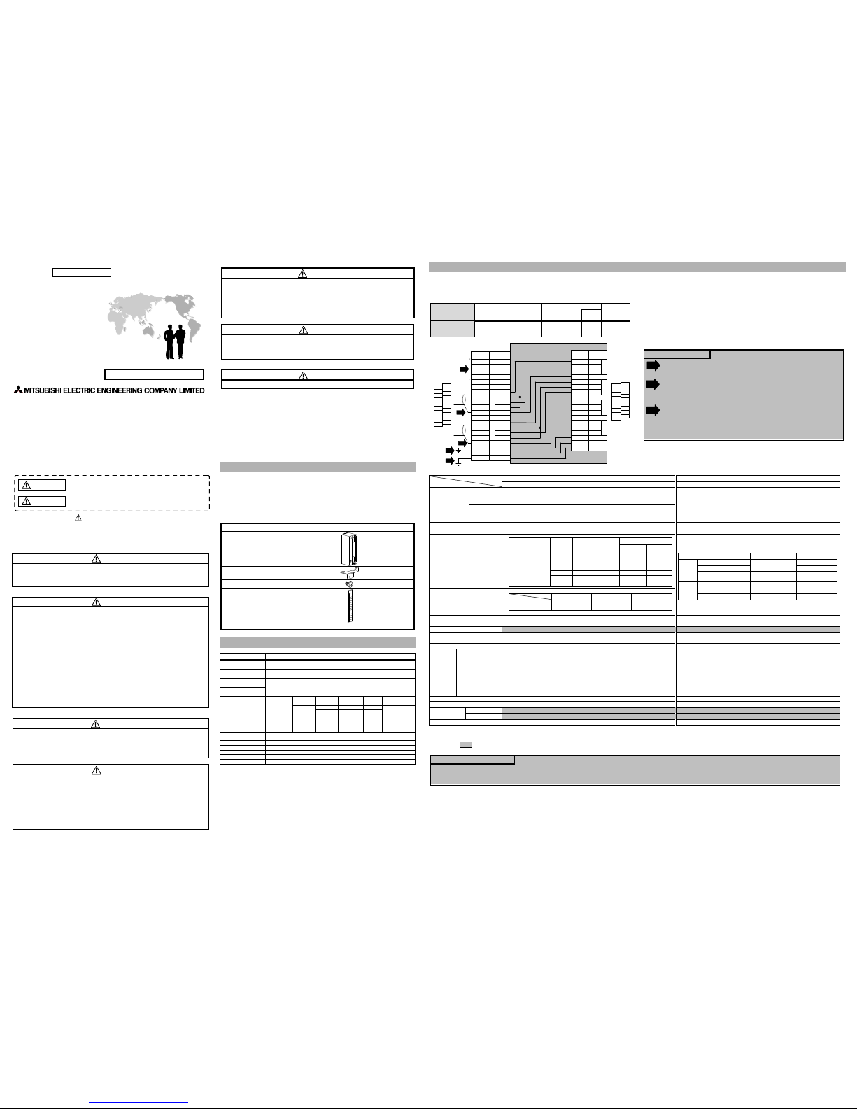
ERNT-ASLT62DA A1S62DA 2 L60DA4 1 75
Internal circuit diagram of E RNT-ASLT62DA
A1S62DA
TerminalBlo ck
L60DA4
Terminal Block
TB2
TB4
TB6
TB8
TB10
TB12
TB14
TB16
TB18
TB20
TB1
TB3
TB5
TB7
TB9
TB11
TB13
TB15
TB17
TB19
TB2
TB4
TB6
TB8
TB10
TB12
TB14
TB16
TB18
TB1
TB3
TB5
TB7
TB9
TB11
TB13
TB15
TB17
-
+
Terminal
No.
TB1
TB2
TB3
TB5
TB6
TB7
TB8
TB9
TB10
TB11
TB12
TB13
TB14
TB15
TB16
TB17
TB18
TB19
TB20
TB4
Signal
Name
24G
FG
V+
COM
I+
C
H
1
C
H
2
C
H
3
C
H
4
Terminal
No.
TB1
TB2
TB3
TB5
TB6
TB7
TB8
TB9
TB10
TB11
TB12
TB13
TB14
TB15
TB16
TB17
TB18
TB4 SLD
V+
COM
I+
SLD
V+
COM
I+
SLD
V+
COM
I+
+24V
*1
*3
*3
*3
*2
Signal
Name
TEST
TEST
Open(24G)
Open(FG)
V+
VI+
I-
C
H
1
C
H
2
V+
VI+
IOpen(SLD)
Open(+24V)
Open(SLD)
Open
Open
Open
HLD/CLR
HLD/CLR
< Specification Comparison >
Model
Specifications
MELSEC-AnS Series MELSEC-L Series
A1S62DA L60DA4
Digital input
Voltage
1/4000:-4000 to 4000
1/8000:-8000 to 8000
1/12000:-12000 to 12000
-20480 to 20479
(When using the scaling function:-32768to 32767)
Current
1/4000:0 to 4000
1/8000:0 to 8000
1/12000:0 to 12000
Analog output
Voltage
-10 to 0 to 10VDC(external l oad resistance:2kΩ to 1MΩ) -10 to 10VDC (external l oad resistance:1kΩ to 1MΩ)
Current
0 to 20mADC (external loadresistance:0Ω t o 600Ω) 0 to 20mADC (external loadresistance:0Ω t o 600Ω)
I/O characteristics
Maximum resolution
Overall accuracy
±1.0% (Voltage output:±100mV, Current o utput:±200μA)
Ambient temperature 25±5℃:Within ±0.1% ( voltage:±10mV, current:±20μA)
Ambient temperature 0 to 55℃:Within±0.3% (voltage :±30mV, current:±60μA)
Maximum conversion speed Maximum 25ms/2 channels (same for 1channel) 20μs/channel
Absolute maximum output
Voltage:±12V
Current:+28mA
−
Analog output points 2 channels 4 channels
Insulation
method
Between output
terminals and
programmable
controller power
supply
Photocoupler insulation Photocoupler insulation
Between terminals
No insulation No insulation
Between external
power supply and
analog output
−
Transformer insulation
Number of occupied I/O points 32 points 16 points
Connected terminal block
20-point terminal block 18-point terminal block
External
power supply
Voltage
− 24VDC +20%,-15%
Current
−
0.18A
Current consumption 0.8A 0.16A
*1:When the offset value i s set to 0V and thegain valueis setto 10V.
*2:When the offset value i s set to 4mA and thegain valueis setto 20mA.
Make sure the section of the above table meetsthe specificationof the machinesand equipmentconnected tothe MELSEC-LSeries module.
Precautions for programming
(1) A1S62DA and L60DA4 differfrom ea ch other in the way input/outputsignals (X, Y)and buffermemory add resses are allocated. Therefore, you needmake necessa ry changes to the sequence programthat is
used.
(2) CH3 and CH4 ofL6 0DA4 cannot be used.
Precautions for wiring
L60DA4 is not provided witha ter minal for Offset/Gain setting or OutputHold/Clear setting
purposes.
Make Output Hold/Clear setting bychoosing an appropriateL60DA4 intelligentfunction
module switch setting.
For more details about theOffset/Gain setting andOutput Hold/Clearsetting, se e the L60DA4
User’s Manual.
L60DA4 requires power supply. Therefore,use the openedterminals(TB18, TB19)of
A1S62DA to provide 24VDC powersupply to L60DA4.
Connect the shield wires o f each channel to the openedterminals (TB11and TB17)of
A1S62DA, and make sure to groundthe FGterminal (TB18)of L60DA4by u sing the opened
terminal (TB20) of A1S62DA.
*1
*2
Resolution 1/4000 1/8000 1/12000
Analog output
Voltage
output
(*1)
Current
output
(*2)
Digital input value
4000 8000 12000 10V 20mA
2000 4000 6000 5V 12mA
0 0 0 0V 4mA
-2000 -4000 -6000 -5V -
-4000 -8000 -12000 -10V -
1/4000 1/8000 1/12000
Voltage output 2.5mV 1.25mV 0.83mV
Current output 5μA 2.5μA 1.7μA
Analog output range Digital value Resolution
Voltage
0 to 5V
0 to 20000
250μV
1 to 5V 200μV
-10 to 10V
-20000 to 20000
500μV
User range setting 333μV
Current
0 to 20mA
0 to 20000
1000nA
4 to 20mA
800nA
User range setting
-20000 to 20000
700nA
*3
Page 2
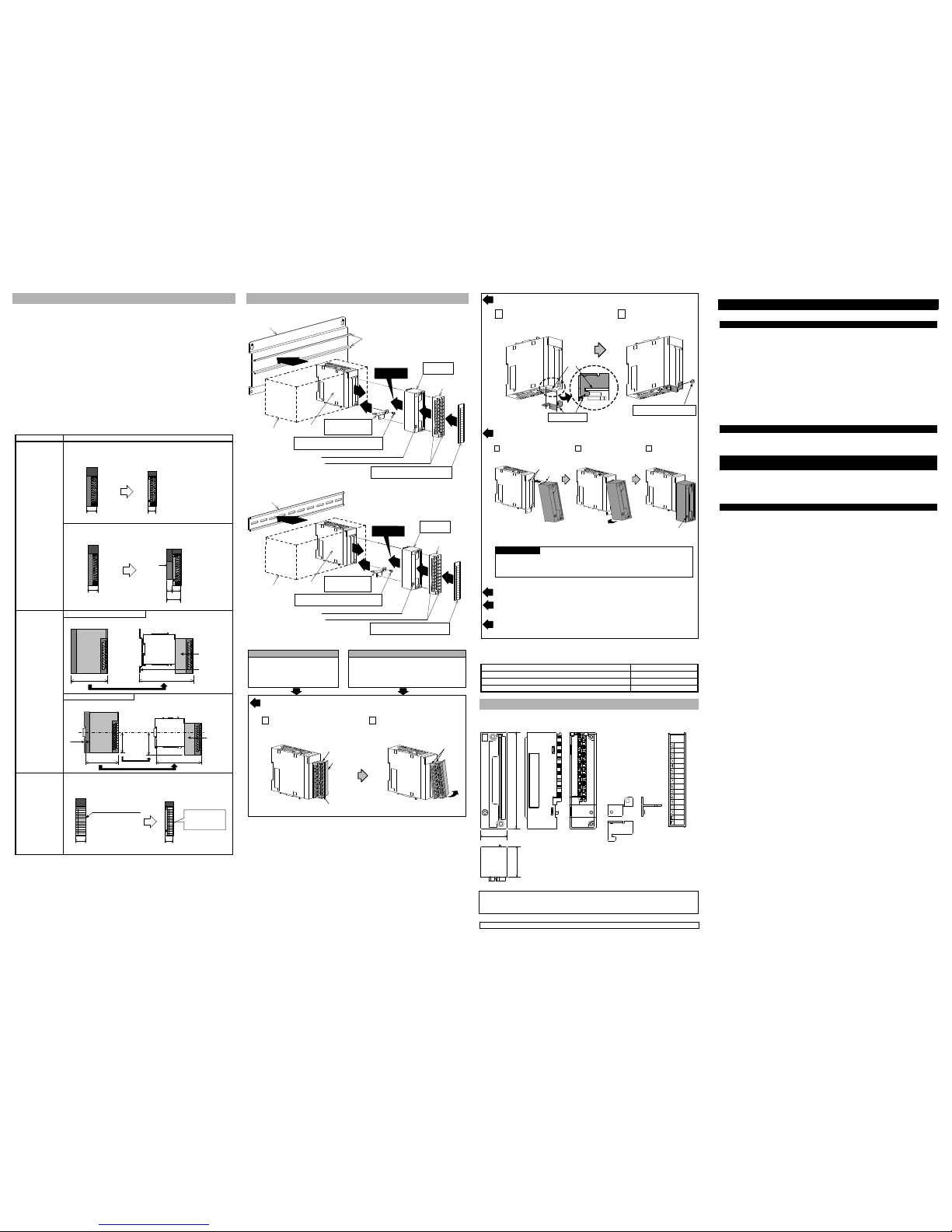
5.Part Names and Installation Method
【Installation with the Base Adapter】
MELSEC-LSeries
Module
Mounting bracket
(supplied with
Conversion Adapter)
Mounting bracket fixing screw M3.5×6
(supplied with Conversion Adapter)
MELSEC-AnSSe ries
terminal block
Terminal block cover
(supplied with Conversion Adapter)
4
2
3
5
6
Conversion
Adapter
MELSEC-AnS Serieste rminalb lock installation screw (M4)
Conversiona dapterins tallation screw M3×25
Precaution
Base Adapter
1
MELSEC-LSeries
System
(DIN rail portion)
【Installation with the DIN rail】
4
2
3
5
6
DIN rail
1
Precaution
MELSEC-LSeries
Module
Mounting bracket
(supplied with
Conversion Adapter)
Mounting bracket fixing screw M3.5×6
(supplied with Conversion Adapter)
MELSEC-AnSSeries
terminalbl ock
Terminal block cover
(supplied with Conversion Adapter)
Conversion
Adapter
MELSEC-AnSSeries terminal block installation screw (M4)
Conversionadapter installation screw M3×25
MELSEC-LSeries
System
5.1 InstallationMethod
Installation with the Base Adapter Installation with the DIN rail
Remove the existing MELSEC-AnS
Series base unit, and i nstall the base
adapter ERNT-ASLB.
For how to install the base adapter,
refer to the base adaptermanual.
Install the DIN rail onthe control panel.
For how to install the DIN rail, refer to the user's
manual of the MELSEC-L CPU module.
Remove the terminal block attachedwith the MELSEC-LSeries moduleafter looseningthe
terminal block installation screw (1 place).
The MELSEC-L series terminal blockis not used.
Terminal block installation screw
Terminal block
Open the terminal cover and l oosen
the terminal block installation screw.
Press the terminal block fixing holesuntil
the lower part of the terminalblock is
disengaged from the module, and then
remove the terminal block.
Terminal block
fixing holes
1 2
Terminal block
cover
Secure the mounting bracket tothe MELSEC-L Seriesmodule usingthe mountingbracket
fixing screws (M3.5 × 6) . (1 place)
Serial number
display
Mounting bracket
Mounting bracket fixing screw
M3.5×6
Position the mounting bracketto the
serial number display areaat the bottom
of the MELSEC-L Seriesmodule.
Tighten the Mounting bracket
fixing screw (M3.5×6).
1 2
(bottom)
Install the Conversion Adapter tothe MELSEC-LSeries module, andsecure i t using the
Conversion Adapter installation screws (M3 ×25) . (1 place)
ConversionAdapter installation
screw M3×25
Fullyinsert the projections on the
topof t heConversion adapter into
thet erminalblock fixing holes.
Press theConversion adapter
until itsnaps into place.
Tightenthe Conversion
Adapter installations crew
(M3×25).
projections
Terminalb lock
fixingholes
1 2 3
Precaution
Before tightening the installation screws,check that the Conversion Adapter has been
securely installed on the MELSEC-LSeries module. Tighteningthe screwsin floating-off
state or tilting state willdamage the ConversionAdapter installationscrews an d the
mounting bracket.
Install the MELSEC-L Series systemto the baseadapter (DINrail portion)or the DINrail.
Secure the MELSEC-AnS Series terminalblock to theCon version Adapter with the supplied
MELSEC-AnS Series terminal block i nstallation screw (M4). (2 places, topand bottom.)
Remove the terminal block cover from the MELSEC-AnS Series terminal block and fit the
terminal block cover supplied withthe Co nversion Adaptor in place.
5.2 TighteningTorque
Tighten the i nstallation screws to the specified torque below.An inappropriate tightening torque could
cause the product to fallor re sult in a short circuit, productfailure ormalfunction.
Screw Location Tightening Torque Range
Mounting bracket fixing screw (M3.5×6)
0.68 to 0.92N・m
Conversion Adapter installation screw (M3×25)
0.43 to 0.57N・m
MELSEC-AnS Series terminal block i nstallation screw (M4 screw)
0.78 to 1.18N・m
6.External Dimensions
102
31.5
28
Terminal block
cover
Mounting bracket
Unit:mm
Conversion adapter
Duplication Prohibited
This manual may not be reproducedin anyform, in partor i n whole, without written permission from
Mitsubishi Electric Engineering Company L imited.
©2014 MITSUBISHI ELECTRIC ENGINEERING COMPANY LIMITED ALL RIGHTS RESERVED
MELSEC is a registered trademarkof Mitsubishi ElectricCorporation.
4.Mounting and Installation
4.1 HandlingPrecautions
(1) Before attempting to install the Unit or carry out the necessary wiring, make certain that the
external power supply, used in the system, is shut off on all three phases. Failure to do so may
result in electric shock ordamage to theproduct.
(2) Do nottouch liveterminals. Thereis a dangerof electricshock ormalfunction.
(3) Do not modify the Conversion Adapter or take it apart. Doing so will cause failure, malfunction,
personal injury, or fire.
(4) Do not touch the energized part of the Conversion Adapter directly. Contact will cause
malfunction or failure in thesystem.
(5) Fasten the Conversion Adapter and the Mounting bracket securely with retaining screws, and
tighten the scr ews by applying torque within specified limits. Loose screws can lead to the
dropping of the Conversion Adapter, or Mounting bracket, possibly causing breakage thereof.
Excessive tightness of the screws can lead to breakage of the screws, Converter Adaptor,
Mounting bracket, or MELSEC-L Series Module, possibly causing the dropping, shorting, and
malfunction thereof.
(6) Use care to prevent foreign materials including cuttings and wiring debris from entering the
Conversion Adapter or the MELSEC-L Series Module. These will be cause for fire, failure or
malfunction.
(7) Do not drop the Conversion Adapter and Mounting Bracket or do not give a strong impact to it.
This will cause damage.
4.2 UsePrecautions
Item Use Precautions
Width dimension
of module
Because the module is r educed in width dimension (34.5mm→28.5mm) and
thus in area available for wiring,check dimensional databefore installing the
module.
34.5mm
28.5mm
<MELSEC-AnS Series>
<MELSEC-L Series>
The wiring may interfere withthe adjacent module.Use ofthe Mitsubishi
LG69 space module is recommended.
34.5mm
28.5mm
<MELSEC-AnS Series>
<MELSEC-L Series>
16.5mm
Space
Module
LG69
45mm
Depth and Height
dimension
Installation with the Base Adapter
Because the module is i ncreased in depth dimension, che ck dimensional
data before installing the module.
110mm
161.3mm
MELSEC-AnS
Conversin
Adapter
Base Adapter
51.3mmUP
MELSEC-L
Installation with the DIN rail
Because the module is i ncreased in depth and height dimension,check
dimensional data before installing themodule.
106mm
144.5mm
38.5mmUP
5.2mmUP
70.2mm
65mm
4mm
MELSEC-AnS
MELSEC-L
Conversin
Adapter
Terminal block
cover
The terminal block cover for MELSEC-AnSSeries is biggerthan thewidth of
the MELSEC-L Series Module. T herefore, it is necessary to replaceit with
the terminal block cover suppliedwith t he converter adapter.
34.5mm
28.5mm
<MELSEC-AnS Series>
<MELSEC-L Series>
Terminal block cover for
the MELSEC-AnS Series
Replace the terminal
block cover with the
one supplied with the
Conversion Adapter.
4.3 InstallationEnvironment
The installation environmenti s the sameas MELSEC-L series CPU Module to use. Refer to the user's
manual of the MELSEC-L Seri es CPU Module to be used.
Product Warranty Details
Please confirm the following productwarranty details priorto productuse.
Gratis Warranty Terms andGratis Warranty Range
If any fault or defect(hereinafter referredto as“Failure”) attributableto MitsubishiElectric Engineering
Company Limited (hereinafter referred to as “MEE”) should occur within the gratis warranty period ,
MEE shall repair the product freeof chargevia thedistributor fromwhom you madeyour purchase.
GratisWarranty Period
The gratis warranty period of this product shall be one (1) year from the date of purchase or
delivery to the designated place.
Note that after manufacture and shipment from MEE, the maximum distribution period shall be
six (6) months, and the gratis warranty period after manufacturing shall be limited to eighteen
(18) months.
In addition, the gratis warranty period for repaired products shall not exceed the gratis warranty
period established prior to repair.
Gratis WarrantyRange
The gratis warranty range shall be li mited to normal use based on theusage conditions, methods
and environment, etc., defined by the terms and precautions, etc., given in the instruction
manual, user’s manual and cautionlabels onthe pro duct.
Warranty Period after Discontinuation of Production
(1) MEE shall offer product repair services (fee applied) for seven (7) years after production of the
product has been discontinued. Discontinuationof pr oduction shall be reported via distributors.
(2) Product supply (including spare parts) is notpossible afterproduction has beendiscontinued.
Exclusion of Opportunity Loss and Secondary Loss from Warranty
Liability
Regardless of the gratis warranty period, MEE shall not be liable for compensation for damages
arising from causes not attributable to MEE, opportunity losses orl ost profits incurred by the user due
to Failur es of MEE pr oducts, damages or secondary damages arising from special circumstances,
whether foreseen or unforeseen by MEE, compensation for accidents, compensation for damages to
products other than MEE products, orcompensation forother work carriedout bythe user.
Changes in Product Specifications
The specifications given in the catalogs, manuals and technical documents are subject to change
without notice.
This document is a new publication, effective April20 14. Specifications are sub ject to change without
notice.
Developed April 2014
50CM-D180172-A
1
2
3
4
5
6
 Loading...