

Page 1
Mitsubishi Electric Programmable Controller
Renewal Tool
Conversion Adapter
Model
ERNT-1Y2Q904914
User’s Manual
50CM-D180259-B(1611)
HEAD OFFICE: Hulic KUDAN BLDG.1-13-5,KUDANKITA CHIYODA-KU,TOKYO 102-0073,JAPAN
NAGOYA ENGINEERING OFFICE:139 SHIMOYASHIKICHO-SHIMOYASHIKI,KASUGAI,AICHI 486- 0906,JAPAN
SAFETY PRECAUTIONS
(Always read these precautions prior to use.)
Before using this product, please read this manual carefully and pay full attention to safety to ensure that
the product is used correctly.
The precautions presented in this manual are concerned with this product only. For Programmable
Controller system safety precautions, refer to the user’s manual of the MELSEC-Q Series CPU Module
to be used.
In this manual, the safety precautions are ranked as “WARNING” and “CAUTION.”
Indicates that incorrect handling may cause hazardous conditions,
resulting in death or severe injury.
WARNING
Indicates that incorrect handling may cause hazardous conditions,
resulting in medium or minor injury and/or property damage.
CAUTION
Note that failure to observe the CAUTION level instructions may lead to a serious consequence
according to the circumstances. Always follow the precautions of both levels because they are important
to personal safety.
Please keep this manual in an easy-to-access location for future reference, and be sure to provide the
manual to the end user.
[Precautions before using]
CAUTION
When making a switch to the MELSEC-Q Series, be sure to consult user's manual supplied with
individual module under the MELSEC-Q Series to confirm differences in various aspects
including performance, function, CPU input/output signals between the two modules.
[Installation Precautions]
CAUTION
Use the Conversion Adapter in the environmental conditions that are specified in the general
specification. If the Products are used in any environment beyond the bounds of the general
specification, electric shock, fire, malfunction, or damage to or degradation of the Products will
result.
Do not directly touch any conductive parts of Conversion Adapter. Contact will cause
malfunction or failure in the system.
Fasten the Conversion Adapter and the Mounting Bracket securely with retaining screws, and
tighten the screws by applying torque within specified limits. Loose screws can lead to the
dropping of the Conversion Adapter or Mounting Bracket, possibly causing breakage thereof.
Excessive tightness of the screws can lead to breakage of the screws, Conversion Adapter,
Mounting Bracket, or MELSEC-Q Series Module, possibly causing the dropping, shorting, and
malfunction thereof.
Always check for correct match between MELSEC-Q Series and the Conversion Adapter.
Incorrect match can cause damage to the MELSEC-Q Series Module.
When installing the Conversion Adapter, take care not to get your hand snagged on the
Mounting Bracket or the like. Injury may result.
When installing or removing the MELSEC-Q Series Module complete with a Converter Adapter,
be sure to hold it with both hands. Dropping may lead to breakage.
[Wiring Precautions]
WARNING
Before attempting to install the Unit or carry out the necessary wiring, make certain that the
external power supply, used in the system, is shut off on all three phases. Failure to do so may
result in electric shock or damage to the product.
After installation and wiring, close the terminal block cover before turning on the module for
operation. Failure to do so may result in electric shock.
CAUTION
Carry out wiring for the Conversion Adapter correctly after checking the specification and
terminal arrangement for the module used. Connecting a power supply with a different voltage
rating or incorrect wiring may cause a fire or failure.
Tighten the terminal installation screws and terminal screw securely by applying torque within
the specified limits. Loose screws will cause short circuit, fire or malfunction. Excessive
tightening will damage the screws or the Conversion Adapter which in turn will cause dropping
of parts, short circuit or malfunction.
Use care to prevent foreign materials including cuttings and wiring debris from entering the
Conversion Adapter or the MELSEC-Q Series Module. These will be cause for fire, failure or
malfunction.
[Startup and Maintenance Precautions]
WARNING
Do not touch live terminals. There is a danger of electric shock or malfunction.
Shut off the external power supply for the system in all phases before cleaning or retightening
the terminal screws. Failure to do so may result in electric shock or cause the MELSEC-Q Series
Module to fail or malfunction. Loose screws can lead to dropping, shorting, and malfunction.
Excessive tightness of the screws can lead to breakage of the screws, Conversion Adapter,
Mounting Bracket, or MELSEC-Q Series Module, possibly causing the dropping, shorting, and
malfunction thereof.
CAUTION
Do not modify the Conversion Adapter or take it apart. Doing so will cause failu re, malfunction,
personal injury, or fire.
Do not drop the Conversion Adapter and Mounting Bracket or do not give a strong impact to
it. This will cause damage.
[Disposal Precautions]
CAUTION
When disposing of the product, treat it as industrial waste.
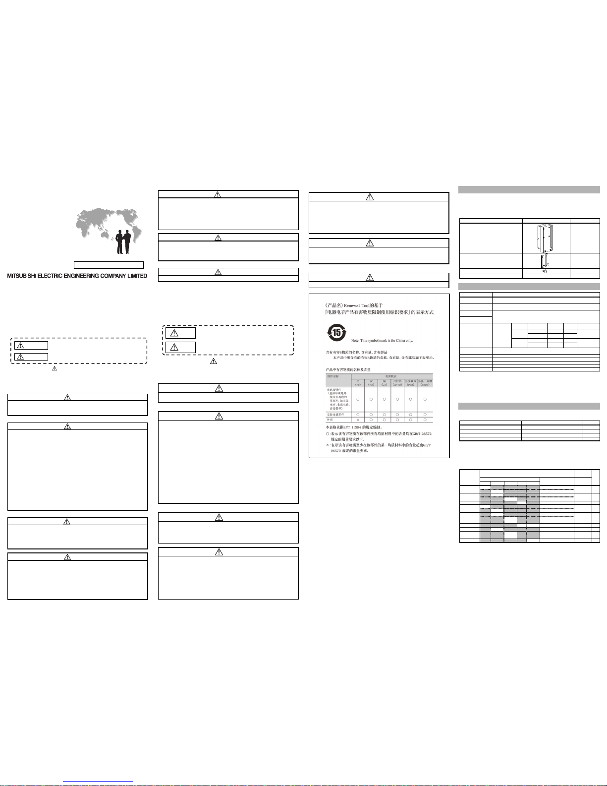
● 安全注意事项 ●
(使用前请务必阅读)
使用本产品时,请仔细阅读本手册,并充分注意安全,正确地使用产品。
本手册中标注的注意事项仅记载了与本产品相关的内容。关于可编程控制器系
统的安全注意事项,请参阅所使用的MELSEC-Q系列CPU模块的用户手册。
在本●安全注意事项●中,安全注意事项的等级分为「警告」和「注意」。
警告
表示错误操作可能造成危险后果,引起死亡或重伤
事故。
注意
表示错误操作可能造成危险后果,引起中度伤害,轻
伤及财产损失。
另
外,根据情况不同,即使是 注意中记载的事项,也可能引发严重后果。不
管哪个记载的都是非常重要的内容,请务必遵守。
请妥善保管本手册,以便需要时取阅,并请将本手册交给最终用户。
【使用前的注意事项】
注 意
● 替换至MELSEC-Q系列时,为确认性能,功能,CPU对应的输入输出信号等
方面的差异,请务必参照MELSEC-Q系列的各模块的手册进行
使用。
【安装注意事项】
注 意
● 应在一般规格环境下使用转换适配器。如果在一般规格范围以外的环境
中使用转换适配器,可能导致触电,火灾,误动作,产品损坏或性能劣
化。
● 请不要直接触摸转换适配器的导电部分。否则可能会造成系统误动作,
故障。
● 转换适配器及安装配件应通过安装螺钉切实地加以固定,安装螺钉应在
规定的扭矩范围内切实地拧紧。如果螺钉拧得过松,有可能因掉落而导致
转换适配器及安装配件破损。如果螺钉拧得过紧,有可能造成螺钉,转换
适配器,安装配件及MELSEC-Q系列模块破损,从而导致掉落,短路或误动
作。
● 请务必确认MELSEC-Q系列模块和转换适配器的组合是否正确。在错误组
合下使用时,可能会导致MELSEC-Q系列模块损
坏。
●
安装转换适配器时,应注意不要使手等身体部分刮到安装配件。否则可
能会导致
受伤。
●
在对安装了转换适配器的 MELSEC-Q 系列模块进行装卸时,请务必用双手
拿住产品。否则会因落下而导致损坏。
【接线注意事项】
警 告
● 在进行安装,配线作业等时,必须将系统使用的外部供应电源全部断开
后再进行操作。如果未全部断开,有可能导致触电或产品
损坏。
●
安装,配线作业完成之 后进行通电,运行时,必须关闭端子排的端子排盖
板。如果未关闭端子排盖板,有可能导致触电。
注 意
● 请确认所使用模块的规格及端子排列后正确地进行转换适配器的接线。
如果输入不符合额定值的电压,连接不符合额定值的电源或接错线,可
能会导致火灾或故
障。
●
端子排安装螺钉,端子螺钉应在规定的扭矩范围内切实地拧紧。如果螺
钉拧得过松,有可能导致短路,火灾或误动作。如果螺钉拧得过紧,有可
能造成螺钉及转换适配器破损从而导致掉落,短路或误动
作。
● 请注
意不要让切屑或接线头等异物进入转换适配器及MELSEC-Q系列模块
内。否则可能会导致火灾,故障,误动作
。
【启动和维护注意事项】
警 告
● 在通电状态下请勿触摸端子。否则可能导致触电或误动作。
● 在清洁模块或重新紧固端子螺钉时,必须将系统使用的外部供应电源全
部断开后再进行操作。如果未全部断开,有可能导致触电或MELSEC-Q系
列模块故障,误动作。如果螺钉拧得过松,有可能导致掉落,短路或误动
作。如果螺钉拧得过紧,有可能导致螺钉,转换适配器,安装配件及
MELSEC-Q系列模块破损,从而导致掉落,短路或误动作。
注 意
● 请不要拆卸,改造转换适配器。否则可能会导致故障,误动作,受伤或火
灾。
● 请勿使转换适配器及安装配件掉落或受到强烈撞击。否则可能导致破损。
【废弃注意事项】
注 意
● 废弃时请将本产品作为工业废弃物处理。
EMC
AND LOW VOLTAGE DIRECTIVES
Compliance to the EMC Directive, which is one of the EU Directives, has been a legal obligation
for the products sold in European countries since 1996 as well as the Low Voltage Directive
since 1997.
Manufacturers who recognize their products are compliant to the EMC and Low Voltage
Directives are required to declare that print a "CE mark" on their products.
Authorized representative in Europe
Authorized representative in Europe is shown below.
Name: Mitsubishi Electric Europe B.V.
Address: Mitsubishi-Electric-Platz 1, 40882 Ratingen, Germany
1.Overview
This manual describes specifications, handling and other information about the Conversion Adapter
“ERNT-1Y2Q904914” available as Renewal Tools for the Mitsubishi Electric Programmable Controller.
Before attempting to make a switch to MELSEC-Q Series in your installation, consult the user's manual
supplied with individual module under the latter series to learn about how they differ in various aspects
including performance and function.
Once you have opened the packaging, verify that it contains the following products.
Product Shape Quantity
Conversion Adapter 1
Mounting Bracket 1
Mounting Bracket fixing screws (M3.5 x 6) 4
This manual
-
1
2.General Specifications
Item Specifications
Operating ambient
temperature
0 to 55℃(Maximum surrounding air temperature 55℃)
Storage ambient
temperature
-25 to 75℃
Operating ambient
humidity
5 to 95%RH,non-condensing
Storage ambient
humidity
Vibration
resistance
Compliant with
JIS B 3502
and
IEC 61131-2
Fr
equency
Constant
acceleration
Half
amplitude
Sweep count
Under
intermittent
vibration
5 to 8.4Hz - 3.5mm
10 times each in
X, Y, Z directions
8.4 to 150Hz 9.8m/s2 -
Under
continuous
vibration
5 to 8.4Hz - 1.75mm
-
8.4 to 150Hz 4.9m/s2 -
Shock resistance
Compliant with JIS B 3502 and IEC 61131-2
(147 m/s
2
, 3 times each in 3 directions X, Y, Z)
Operating atmosphere No corrosive gases
Operating altitude *1 0 to 2000m
Installation location Inside a control panel
Overvoltage category *2 II or less
Pollution degree *3 2
*1:Do not use or store under pressure higher than the atmospheric pressure of altitude 0m.
*2:This indicates the section of the power supply to which the equipment is assumed to be connected between
the public electrical power distribution network and the machinery within premises.
Category II applies to equipment for which electrical power is supplied from fixed facilities.
*3:This index indicates the degree to which conductive material is generated in terms of the environment in
which the equipment is used.
Pollution level 2 is when only non-conductive pollution occurs. A temporary conductivity caused by condensing
must be expected occasionally.
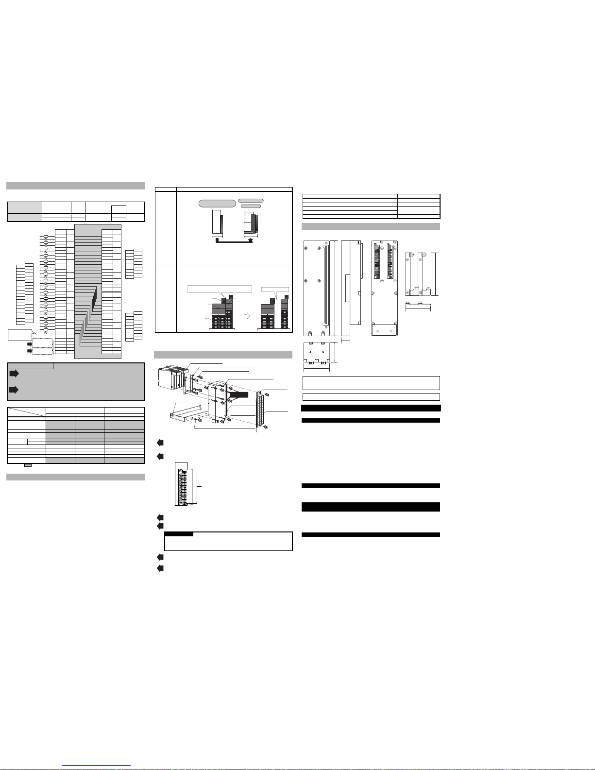
3.Products Required by the Conversion Adapter
(1) Conversion Adapter Anchor Base (Sold Separately)
The Conversion Adapter Anchor Base secures the bottom of the Conversion Adapter. One anchor
base is required per base unit.
Conversion Adapter Anchor Base Model Specifications Weight (g)
ERNT-AQF12 12-slot conversion adapter anchor base 590
ERNT-AQF8 8-slot conversion adapter anchor base 410
ERNT-AQF5 5-slot conversion adapter anchor base 275
ERNT-AQF3 3-slot conversion adapter anchor base 185
(2) Base Adapter (Sold Separately)
Both the MELSEC-Q Series Base Unit and the Conversion Adapter Anchor Base can be installed on
the Base Adapter without drilling screw holes.
However, drilling screw holes (M5 screws) is required to install the Base Adapter to the panel
surface.
For the Base Unit models marked with *1 to *5, two or more Base Adapter models are applicable.
Select the most suitable Base Adapter according to the product dimensions.
Base Adapter
Model
Installable
Product
dimensions
Weight
(g)MELSEC-Q Series Base Unit
Conversion Adapter
Anchor Base
Width×Height
(mm)
12 slots 8 slots 5 slots 3 slots 2 slots
ERNT-AQB38
Q312B
ERNT-AQF12, ERNT-AQF8
480×240 970
Q38B(*1)
ERNT-AQF8
ERNT-AQB35
Q38B(*1)
ERNT-AQF8, ERNT-AQF5
382×240 795
Q35B
ERNT-AQF5
ERNT-AQB32 Q33B
ERNT-AQF3
247×240 675
ERNT-AQB68
Q612B
ERNT-AQF12, ERNT-AQF8
466×240 930
Q68B(*2)
ERNT-AQF8
ERNT-AQB65
Q68B(*2)
ERNT-AQF8, ERNT-AQF5
352×240 790
Q65B(*3)
Q55B(*4)
ERNT-AQF5
ERNT-AQB62 Q63B Q52B(*5)
ERNT-AQF3
238×240 650
ERNT-AQB58 Q68B(*2)
ERNT-AQF8
411×240 870
ERNT-AQB55
Q65B(*3)
Q55B(*4)
ERNT-AQF5
297×240 655
ERNT-AQB52 Q52B(*5)
ERNT-AQF3
183×240 505
Page 2
4.Product Specifications
For detail specifications which do not appear in the specification comparison charts contained herein, see the user's
manual supplied with the MELSEC-Q Series Module you use. Also, ch eck t hat t he sp ecifi catio ns of the
connected devices meet the specifications of the MELSEC-Q Series Module.
Conversion Adapter
Model
Before replacement
Module Model
No. of
output
points
After replacement
MELSEC-Q Series
Module Model
Conversion
Adapter
Weight (g)
No. of
modules
ERNT-1Y2Q904914
JAMSC-B2904 16
QY18A
2
280
JAMSC-B2914 16 2
TB1
MEMOCON-SC
GL Ser ies
(2000 Series I/O)
Module
Internal circuit diagra m of
ERNT-1Y2Q904 914
TB1
TB2
TB3
TB4
TB5
TB6
TB7
TB8
TB9
TB10
TB11
TB12
TB13
TB14
TB15
TB16
TB17
TB18
TB19
TB20
TB21
TB22
TB23
TB24
TB25
TB26
TB27
TB28
TB29
TB30
TB31
TB32
TB33
TB34
TB35
TB36
TB37
TB38
MELSEC-Q
Series
Module
(Slot No.)
MELSEC-Q
Series
Module
(Slot No. +1)
TB1
TB2
TB3
TB4
TB5
TB6
TB7
TB8
TB9
TB10
TB11
TB12
TB13
TB14
TB15
TB16
TB17
TB18
TB1
TB2
TB3
TB4
TB5
TB6
TB7
TB8
TB9
TB10
TB11
TB12
TB13
TB14
TB15
TB16
TB17
TB18
L
TB2
TB3
TB4
TB5
TB6
TB7
TB8
TB9
TB10
TB11
TB12
TB13
TB14
TB15
TB16
TB17
TB18
TB19
TB20
TB21
TB22
TB23
TB24
TB25
TB26
TB27
TB28
TB29
TB30
TB31
TB32
TB33
TB34
TB35
TB36
TB37
TB38
100 to 240VAC
TB1
TB2
TB3
TB4
TB5
TB6
TB7
TB8
Y00
TB9
TB10
TB11
TB12
TB13
TB14
TB15
TB16
TB17 Open
TB18 Open
Y01
Y02
Y03
Y04
Y05
Y06
Y07
Output
1
Output
2
Output
3
Output
4
Output
5
Output
6
Output
7
Output
8
Output
9
Output
10
Output
11
Output
12
Output
13
Output
14
Output
15
Output
16
TB2
TB3
TB4
TB5
TB6
TB7
TB8
Y00
TB9
TB10
TB11
TB12
TB13
TB14
TB15
TB16
TB17 Open
TB18 Open
Y01
Y02
Y03
Y04
Y05
Y06
Y07
Open
Open
24V
0V
FG
FG
L
L
L
L
L
L
L
L
L
L
L
L
L
L
L
FG terminal
is not requierd.
Terminal
No.
Signal
Name
Signal
Name
Terminal
No.
Signal
Name
TB1
*1
*2
External power
supply is not
requierd.
Do not use
110VDC.
Terminal
No.
Precautions for wiring
External power supply connected to the terminal numbers TB35 and TB36 on the
MEMOCON-SC GL Series (2000 Series I/O)-side terminal block becomes unnecessary.
However, that leaving the terminals connected will not cause a problem because the wire is
not connected inside the Conversion Adapter.
FG terminal connected to the terminal numbers TB37 and TB38 on the MEMOCON-SC GL
Series (2000 Series I/O)-side terminal block becomes unnecessary. However, that leaving
the terminals connected will not cause a problem because the wire is not connected inside
the Conversion Adapter.
< Specification Comparison >
Model
Specifications
MEMOCON-SC GL Series
(2000 Series I/O)
MELSEC-Q Series
JAMSC-B2904 JAMSC-B2914 QY18A
No. of output points 16 points 16 points 8 points
Rated switching
voltage/current
DC110V, 0.3A
AC220V, 0.5A
DC110V, 0.3A
AC220V, 0.5A
24VDC, 2A (resistive load)/point
240VAC, 2A (cosφ=1)/point
8A/unit
Minimum switching load 5VDC, 1mA 24VDC, 10mA 5VDC, 1mA
Maximum switching load
110VDC 0.5A
220VAC 15A
110VDC 0.5A
220VAC 15A
125VDC
264VAC
Response
time
OFF to ON
6ms or less 6ms or less 10ms or less
ON to OFF 4ms or less 4ms or less 12ms or less
Surge suppressor None None None
Fuse None None None
Isolation method Relay isolation Relay isolation Relay isolation
Common terminal arrangement All points independent All points independent All points independent
External connection system
38-point
terminal block
38-point
terminal block
18-point
terminal block
Make sure the section of the above table meets the s pecification of the machines and equipment connected to the
MELSEC-Q Series Module.
5.Mounting and Installation
5.1 Handling Precautions
(1) Before attempting to install the Unit or carry out the necessary wiring, make certain that the
external power supply, used in the system, is shut off on all three phases. Failure to do so may
result in electric shock or damage to the product.
(2) Do not touch live terminals. There is a danger of electric shock or malfunction.
(3) Do not modify the Conversion Adapter or take it apart. Doing so will cause failure, malfunction,
personal injury, or fire.
(4) Do not touch the energized part of the Conversion Adaptor directly. Contact will cause
malfunction or failure in the system.
(5) Fasten the Conversion Adapter and the Mounting Bracket securely with retaining screws, and
tighten the screws by applying torque within specified limits. Loose screws can lead to the
dropping of the Conversion Adapter, or Mounting Bracket, possibly causing breakage thereof.
Excessive tightness of the screws can lead to breakage of the screws, Converter Adaptor,
Mounting Bracket, or MELSEC-Q Series Module, possibly causing the dropping, shorting, and
malfunction thereof.
(6) Use care to prevent foreign materials including cuttings and wiring debris from entering the
Conversion Adapter or the MELSEC-Q Series Module. These will be cause for fire, failure or
malfunction.
(7) Do not drop the Conversion Adapter and Mounting Bracket or do not give a strong impact to it.
This will cause damage.
5.2 Use Precautions
Item Use Precautions
Depth
dimension
The depth dimension required for installation is 141.6mm. Check the installation
condition.
MELSEC-Q Series
Renewal Tool
+
MEMOCON-SC GL Series
(2000 Series I/O)
UP
31.6mm
Unit:mm
110
141.6
*The each depth dimension is measured from the panel surface.
MEMOCON-SC GL Series (2000 Series I/O): Base Unit + Input/output Module +
Terminal block, MELSEC-Q Series + Renewal Tool: Base Unit + Input/output
Module + Conversion Adapter + Terminal block
Interference
of the terminal
block
When mounting either of the following Conversion Adapters on the right side of the
Conversion Adapter, leave one slot open between them so that the Conversion
Adapter does not interfere with the terminal block of the existing module.
Conversion Adapters : ERNT-1Y2Q500, ERNT-1JQ33S
Conversion Adapter
Terminal block of the
MEMOCON-SC GL Series
(2000 Series I/O)
The Conversion Adapter interferes with the terminal block
of the MEMOCON-SC GL Series (2000 Ser ies I/O).
Leave one slot open.
Input / Output
Module
Conversion Adapter
・ERNT-1Y2Q500
・ERNT-1JQ33S
5.3 Installation Environment
The installation environment is the same as MELSEC-Q Series CPU Module to use. Refer to the user's
manual of the MELSEC-Q Series CPU Module to be used.
6.Part Names and Installation Method
Mounting Bracket (C onversion A dapter acce ssory)
Mounting Bracket
M3.5×6(C onversi on Adapter ac cessory)
Convers ion Adapter installati on screw
M3×30
Conversion Adapter
bottom installation
screw
M3×20
Conversion Adapter
Anchor Base
Conversion Adapter
Conversion Adapter Anchor Base installation screw
M4×8(Conversion Adapter Anchor Base accessory)
Termina l block
installation crew(M3)
MELSEC-Q Series Module
Precauti on
3
1
2
2
2
2
4
4
4
4
5
5
6
6
MEMOCON-SC
GL Series
(2000 Series I/O)
Terminal block
6.1 Installation Method
① Secure the Conversion Adapter Anchor Base to the Base Adapter or control panel using the
Conversion Adapter Anchor Base installation screws (M4 8) provided as an accessory. (Two
end locations)
② Remove the terminal block attached with the MELSEC-Q Series Module after loosening the
terminal block installation screws (2 places top and bottom).
Secure the Mounting Bracket to the Q Series Module using the Mounting Bracket fixing screws
[M3.5 6 (Conversion Adapter accessory); four upper/lower locations].
③ Mount the Conversion Adapter onto the Mounting Bracket.
④ Secure the Conversion Adapter using the Conversion Adapter installation screws (M3 30; 4
locations).
Precaution
Before tightening the installation screws, check that the Conversion Adapter has been
securely installed on the MELSEC-Q Series Module. Tightening the screws in floating-off state
or tilting state will damage the Conversion Adapter installation screws and the Mounting
Bracket.
⑤ Secure the Conversion Adapter using the Conversion Adapter bottom installation screw (M3
20; 2 location).
⑥ Secure the terminal block of the MEMOCON-SC GL Series (2000 Series I/O) to the Conversion
Adapter with the terminal block installation screws (M3; two upper/lower locations).
6.2 Tightening Torque
Tighten the installation screws to the specified torque below. An inappropriate tightening torque could
cause the product to fall or result in a short circuit, product failure or malfunction.
Screw Location Tightening Torque Range
Conversion Adapter Anchor Base installation screw (M4×8)
1.39 to 1.89N・m
Mounting Bracket fixing screw (M3.5×6)
0.68 to 0.92N・m
Conversion Adapter installation screw (M3×30)
0.43 to 0.57N・m
Conversion Adapter bottom installation screw (M3×20)
Terminal block installation screw (M3)
0.5 to 0.6N・m
7.External Dimensions
Unit:mm
204
41.9
55.2
18.9
92
53.5
Conversion Ada pter
Mounting Bracket
Duplication Prohibited
This manual may not be reproduced in any form, in part or in whole, without written permission from
Mitsubishi Electric Engineering Company Limited.
©2016 MITSUBISHI ELECTRIC ENGINEERING COMPANY LIMITED ALL RIGHTS RESERVED
MELSEC is a registered trademark of Mitsubishi Electric Corporation.
MEMOCON is a registered trademark or a trademark of YASKAWA Electric Corporation.
Product Warranty Details
Please confirm the following product warranty details prior to product use.
Gratis Warranty Terms and Gratis Warranty Range
If any fault or defect (hereinafter referred to as “Failure”) attributable to Mitsubishi Electric Engineering
Company Limited (hereinafter referred to as “MEE”) should occur within the gratis warranty period, MEE
shall repair the product free of charge via the distributor from whom you made your purchase.
Gratis Warranty Period
The gratis warranty period of this product shall be one (1) year from the date of purchase or delivery
to the designated place.
Note that after manufacture and shipment from MEE, the maximum distribution period shall be six
(6) months, and the gratis warranty period after manufacturing shall be limited to eighteen (18)
months.
In addition, the gratis warranty period for repaired products shall not exceed the gratis warranty
period established prior to repair.
Gratis Warranty Range
The gratis warranty range shall be limited to normal use based on the usage conditions, methods
and environment, etc., defined by the terms and precautions, etc., given in the instruction manual,
user’s manual and caution labels on the product.
Warranty Period after Discontinuation of Production
(1) MEE shall offer product repair services (fee applied) for seven (7) years after production of the
product has been discontinued. Discontinuation of production shall be reported via distributors.
(2) Product supply (including spare parts) is not possible after production has been discontinued.
Exclusion of Opportunity Loss and Secondary Loss from Warranty
Liability
Regardless of the gratis warranty period, MEE shall not be liable for compensation for damages arising
from causes not attributable to MEE, opportunity losses or lost profits incurred by the user due to Failures
of MEE products, damages or secondary damages arising from special circumstances, whether foreseen
or unforeseen by MEE, compensation for accidents, compensation for damages to products other than
MEE products, or compensation for other work carried out by the user.
Changes in Product Specifications
The specifications given in the catalogs, manuals and technical documents are subject to change without
notice.
This document is a new publication, effective November 2016. Specifications are subject to change
without notice.
Developed November 2016
50CM-D180259-B
MELSEC-Q Series terminal block installation screw
(Secure it in two places, top and bottom.)
*1
*2
 Loading...