

Page 1

ENGINE
ELECTRICAL
CONTENTS
16-1
CHARGING SYSTEM 2................
GENERAL INFORMATION 2................
SERVICE SPECIFICATIONS 3..............
SPECIAL TOOL 3.........................
ON-VEHICLE SERVICE 4..................
Alternator Output Line Voltage Drop Test 4....
Output Current Test 5.......................
Regulated Voltage Test 7....................
Waveform Check Using An Analyzer 9........
Alternator Relay Continuity Check 10.........
ALTERNATOR 11..........................
STARTING SYSTEM 17................
GENERAL INFORMATION 17..............
SERVICE SPECIFICATIONS 17............
IGNITION SYSTEM 25.................
GENERAL INFORMATION 25..............
SERVICE SPECIFICATIONS 26............
ON-VEHICLE SERVICE 26................
Ignition Coil (With Built-in Power Transistor)
Check 26...................................
Spark Plug Check and Cleaning 27...........
Camshaft Position Sensor Check 28.........
Crank Angle Sensor Check 28...............
Detonation Sensor Check 28.................
IGNITION COIL 29.......................
CRANK ANGLE SENSOR 29..............
CAMSHAFT POSITION SENSOR 30.......
DETONATION SENSOR 31................
STARTER MOTOR 18.....................
Page 2
16-2
ENGINE ELECTRICAL -
CHARGING SYSTEM
GENERAL INFORMATION
The charging system uses the alternator output
to keep the battery charged at a constant level
under various electrical loads.
Charging System
Voltage
OPERATION
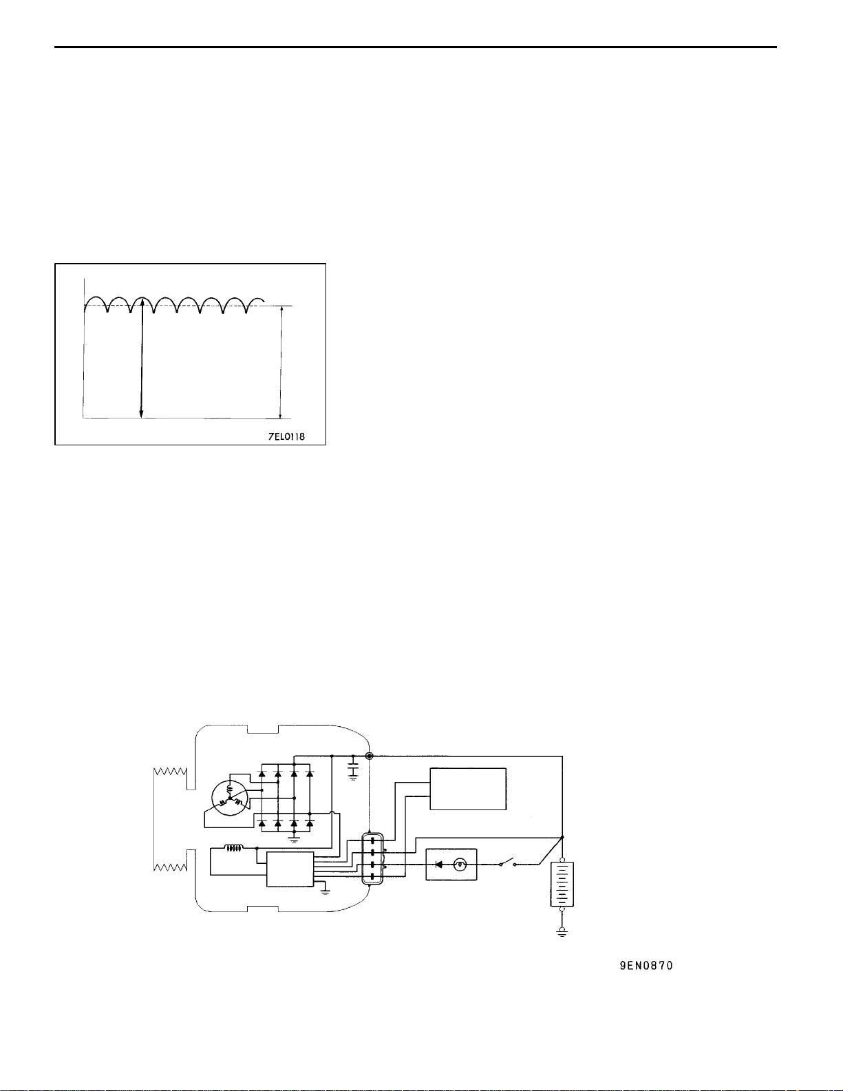
Rotation of the excited field coil generates AC voltage in
the stator.
This alternating current is rectified through diodes to DC
voltage having a waveform shown in the illustration at left.
Approx. 14.4 V
The average output voltage fluctuates slightly with the
alternator load condition.
Time
When the ignition switch is turned on, current flows
in the field coil and initial excitation of the field
coil occurs.
When the stator coil begins to generate power after
the engine is started, the field coil is excited by
the output current of the stator coil.
The alternator output voltage rises as the field
current increases and it falls as the field current
decreases. When t he battery voltage (alternator
S terminal voltage) reaches a regulated voltage
SYSTEM DIAGRAM
<4G9>
of approx. 14.4 V, the field current is cut off. When
the battery voltage drops below t he regulated
voltage, the voltage regulator regulates the output
voltage to a constant level by controlling the field
current.
In addition, when the field current is constant, the
alternator output voltage rises as the engine speed
increases.
Stator coil
Field coil
Voltage
regulator
B
Engine-ECU
G
S
L
FR
Charging
warning lamp
Ignition
switch
+
Battery
-
Page 3
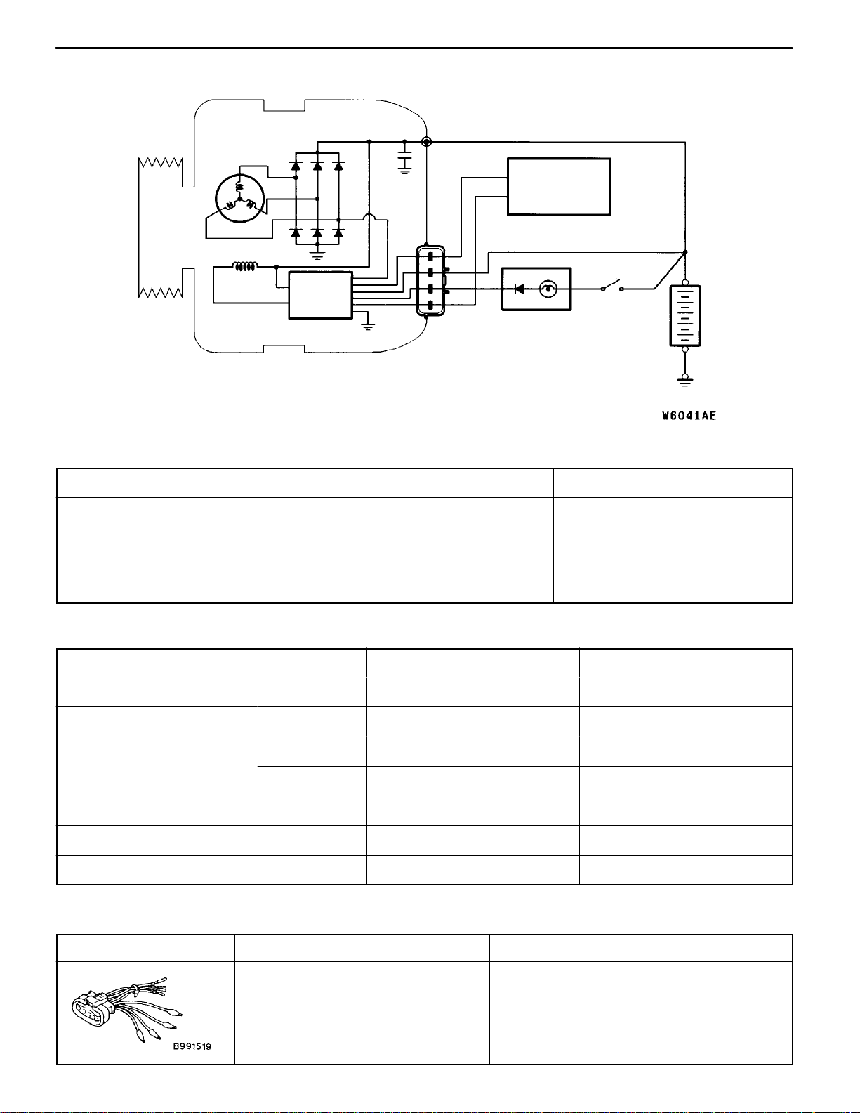
<4G6>
ENGINE ELECTRICAL -
Stator coil
Field coil
Voltage
regulator
Charging System
B
Engine-ECU
G
S
L
FR
Charging
warning lamp
Ignition
switch
16-3
+
Battery
-
ALTERNATOR SPECIFICATIONS
Items 4G9 4G6
Type Battery voltage sensing Battery voltage sensing
Rated output V/A 12/85 <Except cold climate zone>
12/100 <Cold climate zone>
Voltage regulator Electronic built-in type Electronic built-in type
12/100
SERVICE SPECIFICATIONS
Items Standard value Limit
Alternator output line voltage drop (at 30A) V - max. 0.3
Regulated voltage ambient -20_C 14.2- 15.4 temp. at voltage regulator V
20_C 13.9- 14.9 -
60_C 13.4- 14.6 -
80_C 13.1- 14.5 -
Output current - 70% of normal output current
Rotor coil resistance
W
Approx. 2 - 5 -
SPECIAL TOOL
Tool Number Name Use
MB991519 Alternator test
harness
Checking the alternator (S terminal voltage)
Page 4
16-4
ENGINE ELECTRICAL -
Charging System
ON-VEHICLE SERVICE
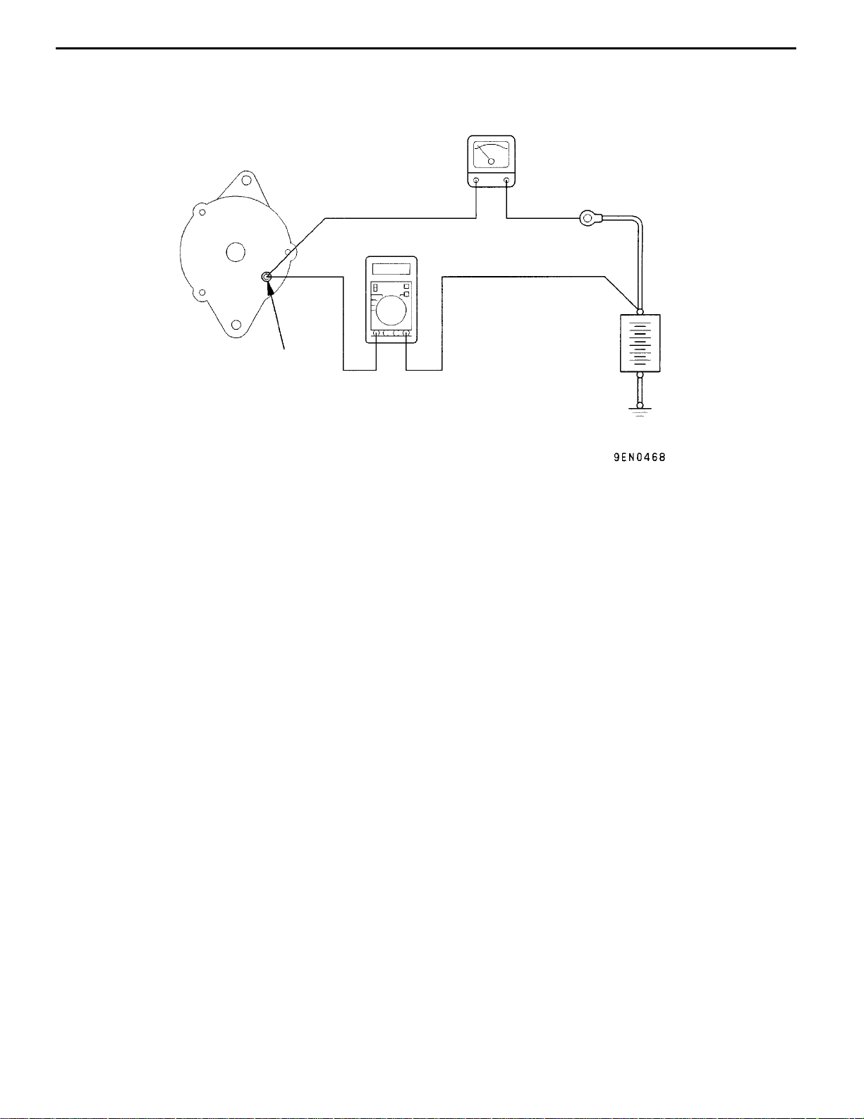
ALTERNATOR OUTPUT LINE VOLTAGE DROP TEST
+-
Alternator
Voltmeter
Terminal B
This test determines whether the wiring from the
alternator “B” terminal to the battery (+) terminal
(including the fusible line) is in a good condition
or not.
1. Always be sure to check the following before
the test.
D
Alternator installation
D
Alternator drive belt tension
D
Fusible link
D
Abnormal noise from the alternator while
the engine is running
2. Turn the ignition switch off.
3. Disconnect the negative battery cable.
4. Disconnect the alternator output wire from the
alternator “B” terminal and connect a DC test
ammeter with a range of 0 - 100 A in series
between the “B” terminal and the disconnected
+-
Ammeter
Battery
output wire. (Connect the (+) lead of the
ammeter to the “B” terminal, and then connect
the (- ) lead of the ammeter to the disconnected
output wire.)
NOTE
An inductive-type ammeter which enables
measurements to be taken without
disconnecting the alternator output wire should
be recommended. Using this equipment will
lessen the possibility of a voltage drop caused
by a loose “B” terminal connection.
5. Connect a digital-type voltmeter between the
alternator “B” terminal and the battery (+)
terminal. (Connect the (+) lead of the voltmeter
to the “B” terminal and the connect the ( - ) lead
of the voltmeter to the battery (+) cable.)
Page 5
ENGINE ELECTRICAL -
Charging System
16-5
6. Reconnect the negative battery cable.
7. Connect a tachometer or the MUT-II.
8. Leave the hood open.
9. Start the engine.
10. With the engine running at 2,500 r/min, turn
the headlamps and other lamps on a n d off
to adjust the alternator load so that the value
displayed on the ammeter is slightly above 30
A.
Adjust the engine speed by gradually
decreasing it until the value displayed on th e
ammeter is 30 A. Take a reading of the value
displayed on the voltmeter at this time.
Limit: max. 0.3 V
NOTE
When the alternator output is high and the value
displayed on the ammeter does not decrease
until 30 A, set the value to 40 A. Read the
value displayed on the voltmeter at this time.
When the value range is 40 A, the limit is max.
0.4 V.
OUTPUT CURRENT TEST
11. If the value displayed on the voltmeter is above
the limit value, there is probably a malfunction
in the alternator output wire, so check the wiring
between the alternator “B” terminal and the
battery (+) terminal (including fusible link).
If a terminal is not sufficiently tight or if the
harness has become discolored due to
overheating, repair and then test again.
12. After the test, run the engine at idle.
13. Turn off all lamps and the ignition switch.
14. Remove the tachometer or the MUT-II.
15. Disconnect the negative battery cable.
16. Disconnect the ammeter an d voltmeter.
17. Connect the alternator output wire to the
alternator “B” terminal.
18. Connect the negative battery cable.
Ignition switch
Battery
Charging warning lamp
Alternator relay
Voltmeter
Ammeter
+-+-
Engine
-ECU
Load
B
FR
L
S
G
Alternator
Page 6

16-6
ENGINE ELECTRICAL -
Charging System
This test determines whether the alternator output
current is normal.
1. Before the test, always be sure to check the
following.
D Alternator installation
D Battery
NOTE
The battery should be slightly discharged.
The load needed by a fully-charged battery
is insufficient for an accurate test.
D Alternator drive belt tension
D Fusible link
D Abnormal noise from the alternator while
the engine is running.
2. Turn the ignition switch off.
3. Disconnect the negative battery cable.
4. Disconnect the alternator output wire from the
alternator “B” terminal. Connect a DC test
ammeter with a range of 0 - 100 A in series
between the “B” terminal and the disconnected
output wire. (Connect the (+) lead of the
ammeter to the “B” terminal. Connect the ( - )
lead of the ammeter to the disconnected output
wire.)
Caution
Never use clips but tighten bolts and nuts
to connect the line. Otherwise loose
connections (e.g. using clips) will lead to
a serious accident because of high current.
NOTE
An inductive-type ammeter which enables
measurements to be taken without
disconnecting the alternator output wire should
be recommended.
5. Connect a voltmeter with a range of 0- 20 V
between the alternator “B” terminal and the
earth. (Connect the (+) lead of the voltmeter
to the “B” terminal, and then connect the (- )
lead of the voltmeter to the earth.)
6. Connect the negative battery cable.
7. Connect a tachometer or the MUT-II.
8. Leave the hood open.
9. Check that the reading on the voltmeter is equal
to the battery voltage.
NOTE
If the voltage is 0 V, the cause is probably
an open circuit in the wire or fusible link between
the alternator “B” terminal and the battery (+)
terminal.
10. Turn the light switch on to turn on headlamps
and then start the engine.
11. Immediately after setting the headlamps to high
beam and turning the heater blower switch to
the high revolution position, increase the engine
speed to 2,500 r/min and read the maximum
current output value displayed on the ammeter.
Limit: 70% of normal current output
NOTE
D For the nominal current output, refer to the
Alternator Specifications.
D Because the current from the battery will
soon drop after the engine is started, the
above step should be carried out as quickly
as possible in order to obtain the maximum
current output value.
D The current output value will depend on
the electrical load and the temperature of
the alternator body.
D If the electrical load is small while testing,
the specified level of current may not be
output even though the alternator is normal.
In such cases, increase the electrical load
by leaving the headlamps turned on for
some time to discharge the battery or by
using the lighting system in another vehicle,
and then test again.
D The specified level of current also may not
be output if the temperature of the alternator
body or the ambient temperature is too
high. In such cases, cool the alternator and
then test again.
12. The reading on the ammeter should be above
the limit value. If the reading is below t he limit
value and the alternator output wire is normal,
remove the alternator from the engine and
check the alternator.
13. Run the engine at idle after the test.
14. Turn the ignition switch off.
15. Remove the tachometer or the MUT-II.
16. Disconnect the negative battery cable.
17. Disconnect the ammeter an d voltmeter.
18. Connect the alternator output wire to the
alternator “B” terminal.
19. Connect the negative battery cable.
Page 7
ENGINE ELECTRICAL -
ENGINE ELECTRICAL -
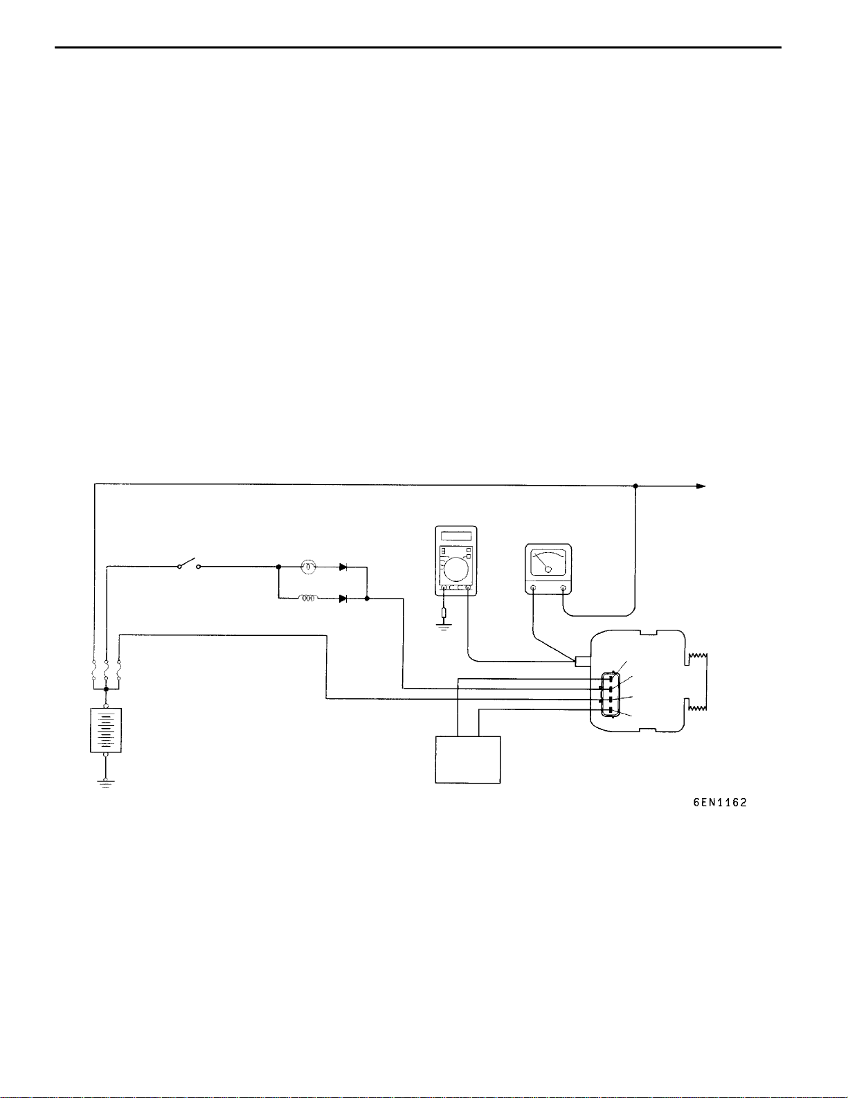
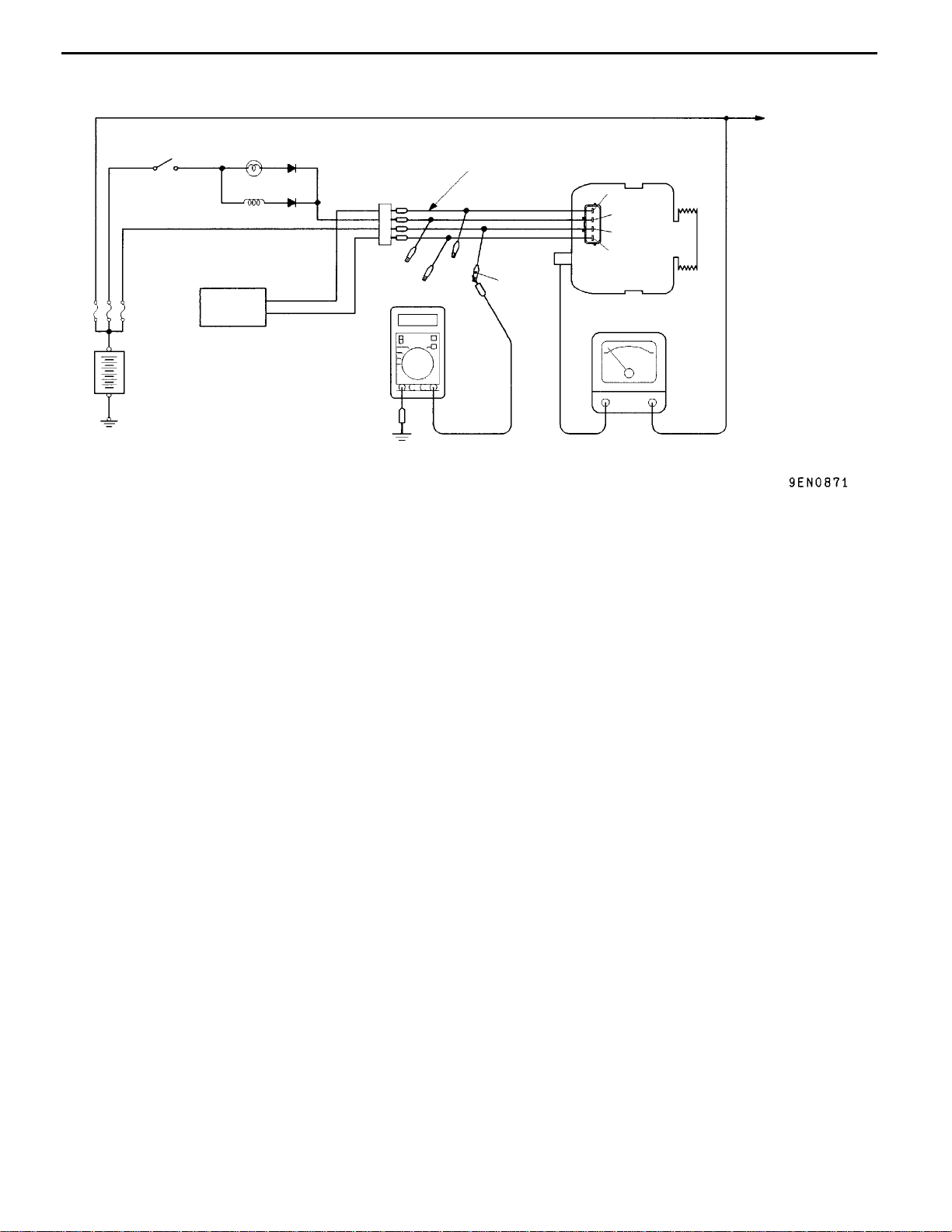
REGULATED VOLTAGE TEST
Ignition
switch
Charging warning
lamp
Alternator relay
EngineECU
MB991519
Charging System
Charging System
Alternator
FR
L
S
B
Yellow
G
Ammeter
16-7
Load
Battery
Voltmeter
-
This test determines whether the voltage regulator
is correctly controlling the alternator output voltage.
1. Always be sure to check the following before
the test.
D
Alternator installation
D
Check that the battery installed in the
vehicle is fully charged.
D
Alternator drive belt tension
D
Fusible link
D
Abnormal noise from the alternator while
the engine is running
2. Turn the ignition switch off.
3. Disconnect the negative battery cable.
4. Use the special tool (Alternator test harness:
MB991519) to connect a digital voltmeter
between the alternator S terminal and earth.
(Connect the (+) lead of the voltmeter to the
”S” terminal, and then connect the (-) lead of
the voltmeter to a secure earth or to the battery
(-) terminal.)
5. Disconnect the alternator output wire from the
alternator “B” terminal.
+
+
-
6. Connect a DC test ammeter with a range of
0 - 100 A in series between the “B” terminal
and the disconnected output wire. (Connect
the (+) lead of the ammeter to the “B” terminal.
Connect the ( - ) lead of the ammeter to the
disconnected output wire.)
7. Reconnect the negative battery cable.
8. Connect a tachometer or the MUT-II.
9. Turn the ignition switch to the ON position a nd
check that the reading on the voltmeter is equal
to the battery voltage.
NOTE
If the voltage is 0 V, the cause is probably
an open circuit in the wire or fusible link between
the alternator “S” terminal and the battery (+)
terminal.
10. Turn all lamps and accessories off.
11. Start the engine.
12. Increase the engine speed to 2,500 r/min.
13. Read the value displayed on the voltmeter when
the alternator output current alternator
becomes 10 A or less.
Page 8

16-8
ENGINE ELECTRICAL -
Charging System
14. If the voltage reading conforms to th e value
in the voltage regulation, then the voltage
regulator is operating normally.
If the voltage is not within the standard value,
there is a malfunction of the voltage regulator
or of the alternator.
15. After the test, lower the engine speed to the
idle speed.
16. Turn the ignition switch off.
Voltage Regulation Table
Standard value:
Inspection terminal Voltage regulator ambient temperature_C Voltage V
Terminal “S” -20 14.2- 15.4
20 13.9- 14.9
60 13.4- 14.6
80 13.1- 14.5
17. Remove the tachometer or the MUT-II.
18. Disconnect the negative battery cable.
19. Disconnect the ammeter an d voltmeter.
20. Connect the alternator output wire to the
alternator “B” terminal.
21. Remove the special tool, and return the
connector to the original condition.
22. Connect the negative battery cable.
Page 9
ENGINE ELECTRICAL -
Charging System
16-9
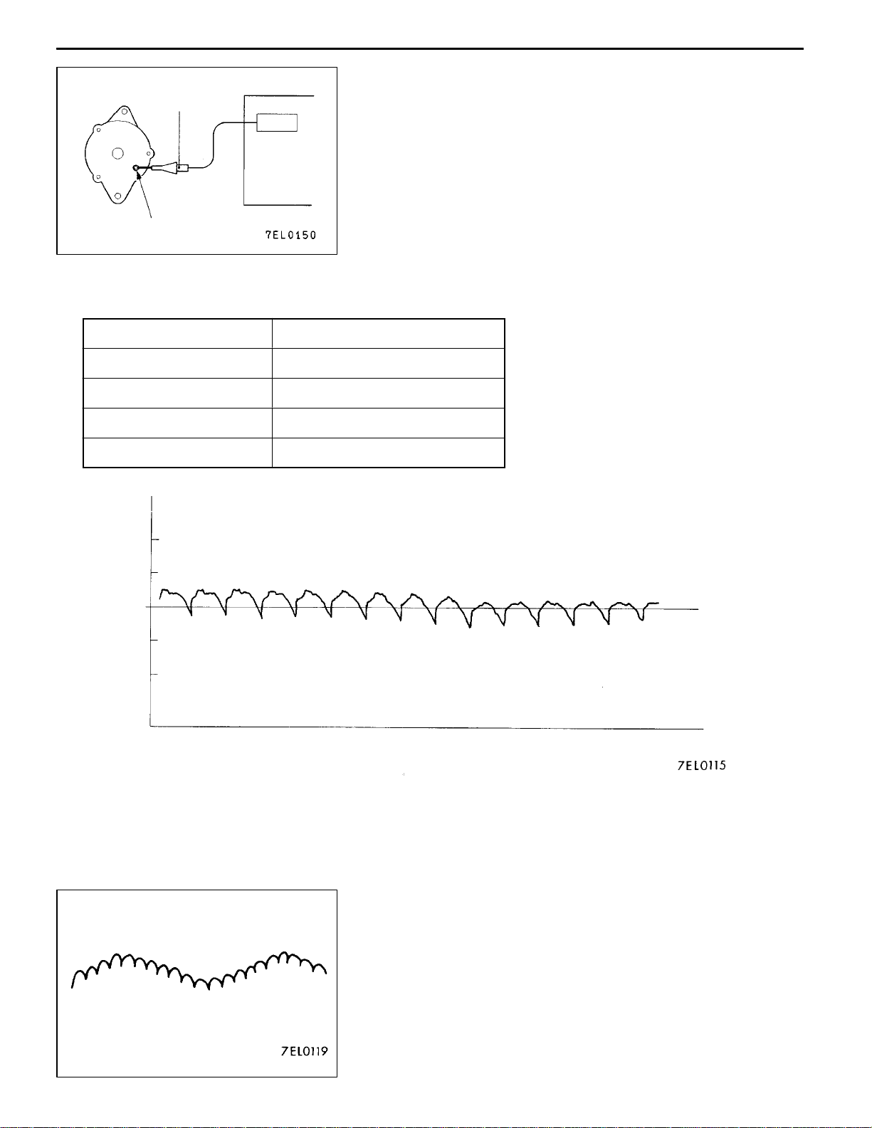
WAVEFORM CHECK USING AN ANALYZER
MEASUREMENT METHOD
Alternator
Special
patterns
pickup
Analyzer
Connect the analyzer special patterns pick-up to th e alternator
B terminal.
B terminal
STANDARD WAVEFORM
Observation Conditions
FUNCTION SPECIAL PATTERNS
PATTERN HEIGHT VARIABLE
VARIABLE knob Adjust while viewing the waveform.
PATTERN SELECTOR RASTER
Engine speed Curb idle speed
Voltage at
alternator
B terminal
0.4
0.2
0
- 0.2
- 0.4
Time
NOTE
The voltage waveform of the alternator B terminal can undulate
as shown at left. This waveform is produced when the regulator
operates according to fluctuations in the alternator load
(current), and is normal for the alternator.
In addition, when the voltage waveform reaches an
excessively high value (approx. 2 V or higher at idle), it often
indicates an open circuit due to a brown fuse between
alternator B terminal and battery, but not a defective alternator.
Page 10
16-10
ENGINE ELECTRICAL -
Charging System
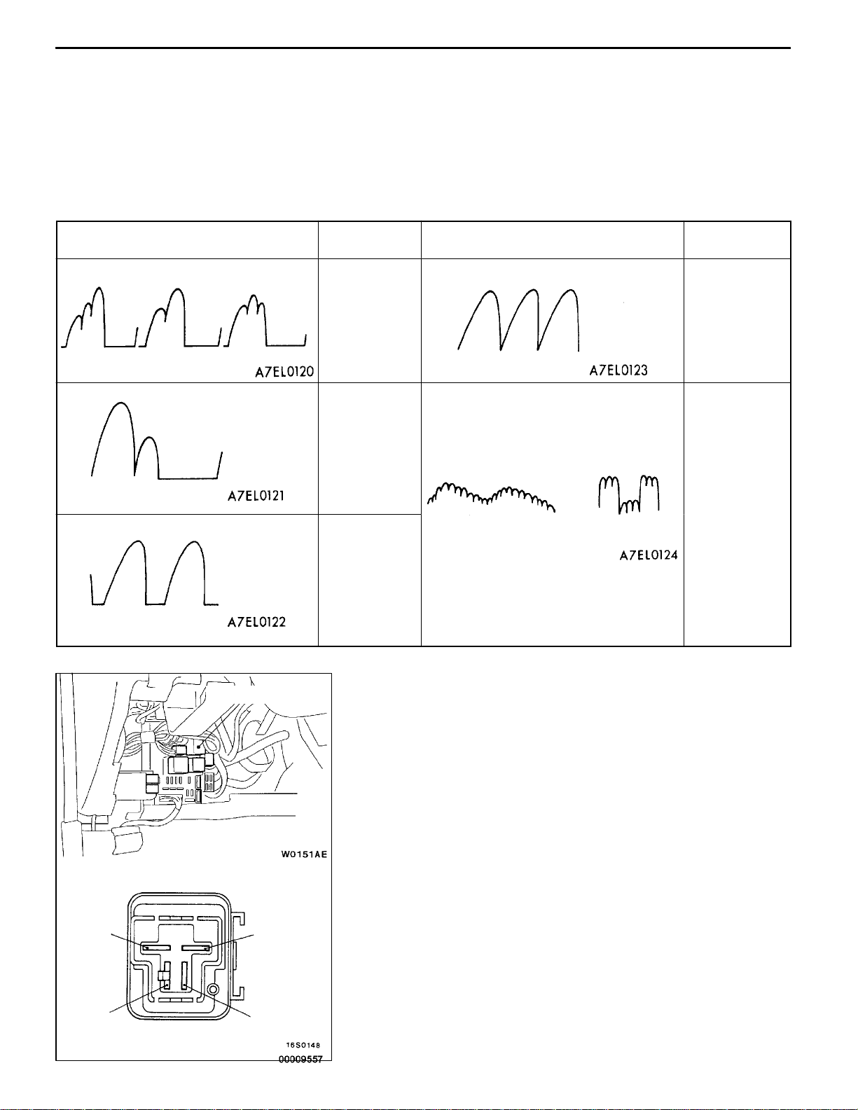
EXAMPLES OF ABNORMAL WAVEFORMS
NOTE
1. The size of the waveform patterns differs largely, depending on the adjustment of the variable knob
on the analyzer.
2. Identification of abnormal waveforms is easier when there is a large output current (regulator is not
operating). (Waveforms can be observed when the headlamps are illuminated.)
3. Check the conditions of the charging warning lamp (illuminated/not illuminated). Also, check the charging
system totally.
Abnormal waveforms Problem
cause
D
D
D
Open
diode
Short in
diode
Broken
wire in
stator coil
Example 1
Example 2
Example 3
Abnormal waveforms Problem
cause
D
D
Short in
stator coil
Open
supplementary
diode
Example 4
Example 5
At this time, the charging warning lamp
is illuminated.
Alternator relay
ALTERNATOR RELAY CONTINUITY CHECK
1. Remove the alternator relay from the relay box inside
the engine compartment.
2. Set the analogue-type circuit tester to the W range and
check that there is continuity when the (+) terminal of
the tester is connected to terminal 2 of the alternator
relay and the ( - ) terminal is connected to terminal 4.
3. Next, check that there is no continuity when the (+) terminal
is connected to terminal 4 and the ( - ) terminal is connected
to terminal 2.
4. If defect is found in steps 2 and 3 above, replace the
alternator relay.
1
3
2
4
Page 11

ENGINE ELECTRICAL -
Charging System
16-11
ALTERNATOR
REMOVAL AND INSTALLATION
Pre-removal Operation
Under Cover and Side Cover (R.H. side) Removal
<4G6>
20 - 25 Nm
1
2
24 Nm
16100140286
Post-installation Operation
D Drive Belt Tension Adjustment
(Refer to GROUP 11 - On-vehicle Service.)
D Under Cover and Side Cover (R.H. side) Installation
5
3
4
<4G9>
49 Nm
20 - 25 Nm
1
5
3
2
49 Nm
4
44 Nm
Removal steps
1. Drive belt (Power steering, A/C)
2. Drive belt (Alternator)
3. Alternator connector
4. Alternator
5. Alternator brace
Page 12

16-12
ENGINE ELECTRICAL -
DISASSEMBLY AND REASSEMBLY
1
Charging System
3
4
5
7
6
2
12
10
9
8
Disassembly steps
AA" 1. Front bracket assembly
AB" 2. Alternator pulley
AB" 3. Rotor
4. Rear bearing
5. Bearing retainer
6. Front bearing
7. Front bracket
14
13
11
AC" 8. Startor
9. Plate
AC""AA 10. Regulator assembly
11. Brush
12. Slinger
13. Rectifier
14. Rear bracket
Page 13

ENGINE ELECTRICAL -
DISASSEMBLY SERVICE POINTS
AA"
Insert flat tip screwdrivers or the like in the clearance between
the front bracket assembly and stator core, to pry open and
separate the stator and front bracket.
Caution
Do not insert the screwdriver too far, or the stator coil
gets damaged.
FRONT BRACKET ASSEMBLY REMOVAL
Charging System
16-13
Soldered
AB"
Face the pulley side upward, fix the rotor with a work bench
and remove the pulley.
Caution
Use care not to damage the rotor.
AC"
1. Unsolder the stator with a soldering iron (180 to 250W).
2. When removing the rectifier from the regulator assembly,
ALTERNATOR PULLEY REMOVAL
STATOR/REGULATOR ASSEMBLY REMOVAL
Complete this work within four seconds not to transfer
heat to the diode.
remove the soldered sections of the rectifier.
Caution
(1) Use careto makesure thatthe heatof thesoldering
iron is not transmitted to the diodes for a long
period.
(2) Use care that no undue force is exerted to the
lead wires of the diodes.
Page 14

16-14
ENGINE ELECTRICAL -
Wire
Rear bracket
Brush
Wire
Charging System
REASSEMBLY SERVICE POINTS
"AA
After installing the regulator assembly, insert a wire into the
hole provided on the rear bracket while pressing in the brush
to fix the brush.
NOTE
The brush is fixed when a wire is inserted, making rotor
installation easier.
REGULATOR ASSEMBLY INSTALLATION
Wire
"BA
ROTOR INSTALLATION
After installing the rotor, remove the wire used to fix the brush.
INSPECTION
16100170216
ROTOR CHECK
1. Check the continuity between the rotor coil slip rings,
and replace the rotor if the resistance value is not at
the standard value.
Standard value: 3 - 5
W
2. Check the continuity between the slip ring an d core, and
if there is continuity, replace the rotor.
Page 15

ENGINE ELECTRICAL -
STATOR CHECK
1. Check the continuity between the coil leads, and if there
is continuity, replace the stator.
2. Check the continuity between the coil and core, and if
there is continuity, replace the stator.
Charging System
16-15
RECTIFIER CHECK
1. Inspect the (+) heat sink by checking the continuity
between the (+) heat sink and stator coil lead wire
connection terminal using a tester probe.
If there is a continuity at both, the diode is short circuited,
so replace the rectifier.
2. Inspect the ( - ) heat sink by checking the continuity
between the ( - ) heat sink and stator coil lead wire
connection terminal using a tester probe.
If there is a continuity at both, the diode is short circuited,
so replace the rectifier.
3. Check the diode trio by connecting an ohmmeter to both
ends of each diode and check the continuity of the three
diodes.
If there is a continuity at both ends, or if there is no
continuity, the diode is damaged so replace the rectifier.
Page 16

16-16
Protrusion
length
ENGINE ELECTRICAL -
BRUSH CHECK
1. Measure the length of the brush protrusion shown in the
illustration, and replace the brush if th e measured value
is below the limit value.
Limit: 2 mm or less
Charging System
Soldered
2. The brush can be removed if the solder of the brush
lead wire is removed.
3. When installing a new brush, insert the brush into the
holder as shown in the illustration, and then solder the
lead wires.
Page 17

ENGINE ELECTRICAL -
STARTING SYSTEM
GENERAL INFORMATION
Starting System
16-17
If the ignition switch is turned to the ”START”
position, current flows in the pull-in and holding
coils provided inside magnetic switch, attracting
the plunger. When the plunger is attracted, the
lever connected to the plunger is actuated to
engage the starter clutch.
On the other hand, attracting the plunger will turn
on the magnetic switch, allowing the B terminal
SYSTEM DIAGRAM
Ignition
switch
Battery
Brush
and M terminal to conduct. Thus, current flows to
engage the starter motor.
When the ignition switch is returned to t he “ON”
position after starting the engine, the starter clutch
is disengaged from the ring gear.
An overrunning clutch is provided between the
pinion and the armature shaft, to prevent damage
to the starter.
Holding coil
Pull-in coil
Armature
Yoke
Plunger
Lever
Over-running
clutch
Pinion shaft
STARTER MOTOR SPECIFICATIONS
Items 4G9 4G6
Type Reduction drive with planetary gear Reduction drive with planetary gear
Rated output kW/V 1.2/12 1.4/12
No. of pinion teeth 8 8
SERVICE SPECIFICATIONS
Items Standard value Limit
Pinion gap mm 0.5 - 2.0 -
Commutator outer diameter mm 29.4 28.8
Commutator runout mm 0.05 0.1
Commutator undercut mm 0.5 0.2
Page 18

16-18
ENGINE ELECTRICAL -
Starting System
<4G9>
<4G6>
B
Battery
S
Switch
M
Wire
Switch
Wire
M
Battery
S
STARTER MOTOR
INSPECTION
PINION GAP ADJUSTMENT
1. Disconnect field coil wire from M-terminal of magnetic
switch.
2. Connect a 12V battery between S-terminal and
M-terminal.
3. Set switch to “ON”, and pinion will move out.
Caution
This test must be performed quickly (in less than
10 seconds) to prevent coil from burning.
B
4. Check pinion to stopper clearance (pinion gap) with a
thickness gauge.
Pinion
Pinion gap: 0.5 - 2.0 mm
Stopper
Pinion gap
5. If pinion gap is out of specification, adjust by adding or
removing gaskets between magnetic switch and front
bracket.
Page 19

ENGINE ELECTRICAL -
Starting System
16-19
<4G9>
<4G6>
<4G9>
<4G6>
Battery
MAGNETIC SWITCH PULL-IN TEST
S
M
Battery
1. Disconnect field coil wire from M-terminal of magnetic
switch.
2. Connect a 12V battery between S-terminal and
M-terminal.
Caution
Wire
This test must be performed quickly (in less than
10 seconds) to prevent coil from burning.
3. If pinion moves out, then pull-in coil is good. If it doesn’t,
replace magnetic switch.
S
M
Wire
MAGNETIC SWITCH HOLD-IN TEST
S
1. Disconnect field coil wire from M-terminal of magnetic
switch.
Battery
2. Connect a 12V battery between S-terminal and body.
Caution
This test must be performed quickly (in less than
Wire
10 seconds) to prevent coil from burning.
3. Manually pull ou t the pinion as far as the pinion stopper
position.
4. If pinion remains out, everything is in order. If pinion moves
in, hold-in circuit is open. Replace magnetic switch.
Battery
S
Wire
Page 20

16-20
ENGINE ELECTRICAL -
Starting System
<4G9>
B
Starter
motor
<4G6>
M
Starter
motor
<4G9>
S
Carbon-pile rheostat
M
Ammeter
A
FREE RUNNING TEST
1. Place starter motor in a vise equipped with soft jaws
and connect a fully-charged 12-volt battery to starter motor
as follows:
2. Connect a test ammeter (100-ampere scale) and carbon
pile rheostat in series with battery positive post and starter
motor terminal.
3. Connect a voltmeter (15-volt scale) across starter motor.
V
Voltmeter
Battery
4. Rotate carbon pile to full-resistance position.
Carbon-pile rheostat
S
5. Connect battery cable from battery negative post to starter
motor body.
6. Adjust the rheostat until the battery voltage shown by
B
Ammeter
the voltmeter is 11 V.
7. Confirm that the maximum amperage is within the
Battery
Voltmeter
specifications and that the starter motor turns smoothly
and freely.
Current: max. 90 Amps
MAGNETIC SWITCH RETURN TEST
1. Disconnect field coil wire from M-terminal of magnetic
switch.
M
Battery
2. Connect a 12V battery between M-terminal and body.
Caution
This test must be performed quickly (in less than
Wire
10 seconds) to prevent coil from burning.
3. Pull pinion out and release. If pinion quickly returns to
its original position, everything is in order. If it doesn’t,
replace magnetic switch.
<4G6>
Battery
Caution
Be careful not to get your fingers caught when pulling
out the pinion.
M
Wire
Page 21

ENGINE ELECTRICAL -
DISASSEMBLY AND REASSEMBLY
13
14
16
Starting System
2
16-21
12
11
15
1
21
4
20
18
19
3
17
22
8
7
5
6
9
10
Disassembly steps
1. Screw
AA" 2. Magnetic switch
3. Screw
4. Through bolt
5. Rear bracket
6. Brush holder
7. Brush
8. Rear bearing
AB" 9. Armature
10. Yoke assembly
AB" 11. Ball
12. Packing A
13. Packing B
14. Plate
15. Planetary gear
16. Lever
AC""AA 17. Snap ring
AC""AA 18. Stop ring
19. Overrunning clutch
20. Internal gear
21. Planetary gear holder
22. Front bracket
Page 22

16-22
ENGINE ELECTRICAL -
Starting System
Magnetic
switch
Stop ring
S terminal
M terminal
Field coil
wire
Socket
Pinion gear
DISASSEMBLY SERVICE POINTS
AA"
AB"
AC"
1. Using an appropriate wrench socket, push the stop ring
MAGNETIC SWITCH REMOVAL
Disconnect the field coil wire from terminal M of the
magnetic switch.
ARMATURE AND BALL REMOVAL
When removing the armature, do not lose the ball placed
at the end as a bearing.
SNAP RING/STOP RING REMOVAL
toward the overrunning clutch.
Snap ring
Pinion gear
Overrunning
clutch
Overrunning
clutch
Snap ring pliers
2. Remove the snap ring with snap ring pliers and then
remove the stop ring and overrunning clutch.
STARTER MOTOR PARTS CLEANING
1. Do not immerse the parts in cleaning solvent. Immersing
the yoke and field coil assembly and/or armature will
damage insulation. Wipe these parts with a cloth only.
2. Do not immerse the drive unit in cleaning solvent. The
overrunning clutch is pre-lubricated at the factory and
solvent will wash lubrication from clutch.
3. The drive unit may be cleaned with a brush moistened
with cleaning solvent and wiped dry with a cloth.
Page 23

Stop ring
Overrunning
clutch
Snap ring
ENGINE ELECTRICAL -
REASSEMBLY SERVICE POINTS
"AA
Using an appropriate tool, pull the stop ring over the snap
ring.
Stop ring
STOP RING/SNAP RING INSTALLATION
INSPECTION
COMMUTATOR
1. Place the armature in a pair of “V” blocks and check
the runout with a dial indicator.
Standard value: 0.05 mm
Limit: 0.1 mm
Starting System
16-23
Segment
Undercut
Mica
Free
2. Measure the commutator outer diameter.
Standard value: 29.4 mm
Limit: 28.8 mm
3. Check the undercut depth between segments.
Standard value: 0.5 mm
Limit: 0.2 mm
OVERRUNNING CLUTCH
1. Check that the pinion locks when it is turned
counterclockwise and moves smoothly when it is turned
clockwise.
2. Check the pinion for wear or damage.
Lock
Page 24

16-24
ENGINE ELECTRICAL -
BRUSH
1. Check the brush for roughness of the surface that contacts
the commutator and check the brush length.
Limit: Wear limit line
2. In case the contacting surface has been corrected or
Wear limit line
the brush has been replaced, correct the contacting
surface by winding sandpaper around the commutator.
Starting System
Growler
ARMATURE COIL SHORT-CIRCUIT TEST
1. Place armature in a growler.
2. Hold a thin steel blade parallel and just above while rotating
armature slowly in growler. A shorted armature will cause
blade to vibrate and be attracted to the core. Replace
shorted armature.
Caution
Clean the armature surface thoroughly before
checking.
3. Check the insulation between each commutator segment
and armature coil core.
If there is no continuity, the insulation is in order.
ARMATURE COIL OPEN-CIRCUIT INSPECTION
Check the continuity between segments. If there is continuity,
the coil is in order.
Page 25

ENGINE ELECTRICAL -
IGNITION SYSTEM
GENERAL INFORMATION
Ignition System
16-25
This system is equipped with four ignition coils with
built-in power transistors for each of the cylinders.
Interruption of the primary current flowing in the
primary side of an ignition coil generates a high
voltage in the secondary side of the ignition coil.
The high voltage thus generated is applied to the
spark plugs to generate sparks.
The engine-ECU turns the power transistors inside
the ignition coils alternately on and off. This causes
the primary currents in the ignition coils to be
alternately interrupted and allowed to flow to fire
the cylinders in the order 1 - 3 - 4 - 2.
SYSTEM DIAGRAM
Air flow sensor
Barometric pressure sensor
Intake air temperature sensor
Engine coolant temperature
sensor
Accelerator pedal position
switch <4G6>
Camshaft position sensor
Crank angle sensor
Ignition switch-ST
Detonation sensor
Vehicle speed sensor
Inhibitor switch <A/T>
EngineECU
The engine-ECU determines which ignition coil
should be controlled by means of the signals from
the camshaft position sensor and the crank angle
sensor. It also detects th e crankshaft position, in
order to provide ignition at the most appropriate
timing in response to the engine operation
conditions.
When the engine is cold or running at high altitudes,
the ignition timing is slightly advanced to provide
optimum performance. Furthermore, if knocking
occurs, th e ignition timing is gradually retarded until
knocking ceases.
Ignition switch
Ignition coil
Battery
Spark plug
To tachometer
Cylinder No.
1
IGNITION COIL SPECIFICATION
Items Specification
Type Molded 4-coil
SPARK PLUG SPECIFICATION
Items 4G6 4G9
NGK IZFR5B IZFR6B
2
43
Page 26

16-26
ENGINE ELECTRICAL -
Ignition System
SERVICE SPECIFICATIONS
SPARK PLUG
Items Standard value Limit
Spark plug gap mm 0.5 - 0.6 0.75
Spark plug insulation resistance MW - 1
ON-VEHICLE SERVICE
1.5 V
+
-
+
-
IGNITION COIL (WITH BUILT-IN POWER
TRANSISTOR) CHECK
PRIMARY COIL AND POWER TRANSISTOR
CONTINUITY CHECK
NOTE
1. An analogue-type circuit tester should be used.
2. Connect the negative ( - ) prove of the circuit tester to
terminal 1.
Caution
This test must be performed quickly (in less than 10
seconds) to prevent coil from burning and power
transistor from breakage.
Voltage: 1.5V
When current is
flowing
When current is
not flowing
SECONDARY COIL CHECK
NOTE
It is impossible to check the secondary coil through the
continuity check as a diode is integrated in the secondary
coil circuit of this ignition coil. So, check the secondary coil
in the following procedure.
1. Disconnect the ignition coil connector.
2. Remove the ignition coil and install a new spark plug
to the ignition coil.
3. Connect the ignition coil connector.
4. Earth the side electrode of the spark plug and crank
the engine.
Terminal No.
1 2 3
Page 27

ENGINE ELECTRICAL -
5. Check that spark is produced between the electrodes of
the spark plug.
6. If no spark is produced, replace the ignition coil with a
new one and recheck.
7. If spark is produced with the new ignition coil, replace
the old one as it is faulty. If no spark is produced again,
the ignition circuit is suspected as faulty. Check theignition
circuit.
SPARK PLUG CHECK AND CLEANING
Caution
1. The spark plug gap for iridium plugs should not be
adjusted.
2. Cleaning iridium plugs may result in damage to the
iridium tip. Therefore, if cleaning is necessary
because the plug is sooty, use a plug cleaner, and
do not clean the plug for more than 20 seconds in
order to preserve the electrodes. A wire brush should
never be used.
3. The spark plugs in GDI engines are special iridium
plugs in which the electrodes can become black even
when the plugs are working normally. Carbon which
may become deposited on these plugs burns off more
readily than with conventional plugs, and so should
not cause any problems with spark plug performance.
Judgement of whether a spark plug is operating
normally or not should be made by checking the
insulation resistance.
Ignition System
16-27
1. Remove the ignition coils.
2. Remove the spark plugs.
3. Check the spark plug gap. Replace the spark plug if the
gap exceeds the limit.
Limit: 0.75 mm
Standard value: 0.5 - 0.6 mm
4. Measure the spark plug insulation resistance. Replace
the spark plug if the measured value is lower than the
limit value.
Limit: 1 M
5. Clean the spark plug holes.
6. Install the spark plugs.
7. Install the ignition coils.
W
Page 28

16-28
ENGINE ELECTRICAL -
CAMSHAFT POSITION SENSOR CHECK
Refer to GROUP 13A - Troubleshooting <4G6> or GROUP
13B - Troubleshooting <4G9>.
CRANK ANGLE SENSOR CHECK
Refer to GROUP 13A - Troubleshooting <4G6> or GROUP
13B - Troubleshooting <4G9>.
DETONATION SENSOR CHECK
Check the detonation sensor circuit if self-diagnosis code,
No. 31 is shown.
NOTE
For information concerning the self-diagnosis codes, refer
to GROUP 13A - Troubleshooting <4G6> or GROUP 13B
- Troubleshooting <4G9>.
Ignition System
Page 29

ENGINE ELECTRICAL -
Ignition System
16-29
IGNITION COIL
REMOVAL AND INSTALLATION
Pre-removal and Post-installation Operation
Engine Cover Removal and Installation
10 Nm
3
25 Nm
16300320174
2
1
Removal steps
1. Ignition coil connector
2. Ignition coil
3. Spark plug
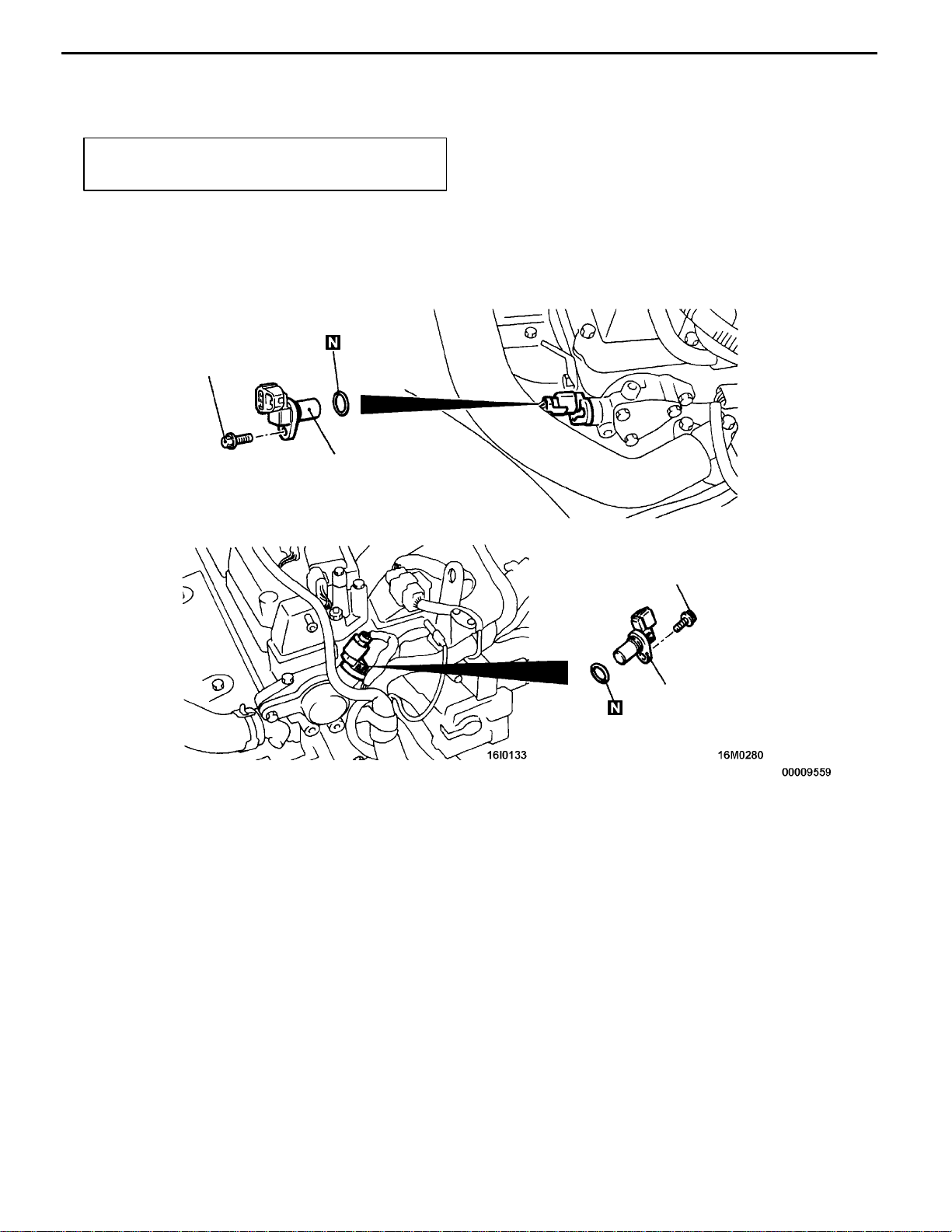
CRANK ANGLE SENSOR
REMOVAL AND INSTALLATION
Pre-removal and Post-installation Operation
D Timing Belt Removal and Installation <4G6>
(Refer to GROUP 11A.)
<4G6> <4G9>
10 - 12 Nm
Crank angle sensor
16300350036
D Timing Belt Front Lower Cover Removal and
Installation <4G9> (Refer to GROUP 11B.)
10 - 12 Nm
Crank angle sensor
9Nm
9Nm
Page 30
16-30
ENGINE ELECTRICAL -
Ignition System
CAMSHAFT POSITION SENSOR
REMOVAL AND INSTALLATION
Pre-removal and Post-installation Operation
Engine Cover Removal and Installation
<4G6>
9Nm
Camshaft position sensor
<4G9>
16300340026
9Nm
Camshaft position sensor
Page 31

ENGINE ELECTRICAL -
Ignition System
16-31
DETONATION SENSOR
REMOVAL AND INSTALLATION
Caution
Do not subject the detonation sensor to any shocks.
Pre-removal and Post-installation Operation
D Engine Cover Removal and Installation
D Air Cleaner Assembly Removal and Installation
<4G6>
D Intake Manifold Stay Removal and Installation
16300280144
(Refer to GROUP 15.)
1
20 - 25 Nm
<4G9>
AA""AA
1. Detonation sensor
10 - 12 Nm
REMOVAL SERVICE POINT
AA"
DETONATION SENSOR REMOVAL
1
20 - 25 Nm
MD998773
INSTALLATION SERVICE POINT
"AA
DETONATION SENSOR INSTALLATION
Page 32

NOTES
 Loading...