

Page 1

ENGINE
COOLING
14-1
CONTENTS
GENERAL INFORMATION 2..................
SERVICE SPECIFICATIONS 2.................
LUBRICANT 2...............................
SEALANTS 2................................
SPECIAL TOOL 3............................
TROUBLESHOOTING 3.......................
ON-VEHICLE SERVICE 8.....................
Engine Coolant Leak Checking 8................
Radiator Cap Opening Pressure
Check 8.......................................
14109000208
Engine Coolant Replacement 9..................
Concentration Measurement 10..................
Fan Controller Check 10........................
Fan Control Relay Continuity Check 11..........
THERMOSTAT 12...........................
WATER PUMP
<4G6> 14................................
<4G9> 15................................
WATER HOSE AND WATER PIPE 16........
RADIATOR 19...............................
Page 2
14-2
ENGINE COOLING -
General Information/Service Specifications/Lubricant/Sealants
GENERAL INFORMATION
The cooling system is designed to keep every part
of the engine at appropriate temperature in
whatever condition the engine may be operated.
The cooling method is of the water-cooled, pressure
forced circulation type in which the water pump
pressurizes coolant and circulates it throughout the
engine. If the coolant temperature exceeds the
prescribed temperature, the thermostat opens to
circulate the coolant through the radiator as well
so that the heat absorbed by the coolant may be
radiated into the air.
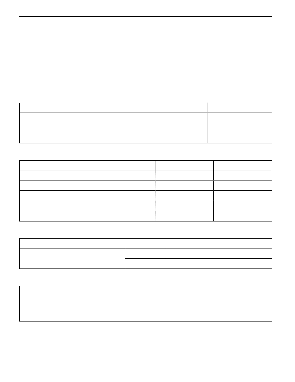
Items Specifications
Radiator Performance kJ/h 4G6 205,116
A/T oil cooler Performance kJ/h 5,860
The water pump is of the centrifugal type and is
driven by the timing belt or drive belt from the
crankshaft.
The radiator is the corrugated fin, down flow type
and is cooled by the electrical radiator fan.
The cooling fans are controlled by a fan controller
and the engine-ECU depending on driving
conditions.
4G9 171,628
SERVICE SPECIFICATIONS
Items Standard value Limit
14100010217
14100030091
Radiator cap opening pressure kPa 74 - 103 64
Range of coolant antifreeze concentration of radiator % 30 - 60 -
Thermostat Valve opening temperature of thermostat_C 85±1.5 -
Full-opening temperature of thermostat_C 98 -
Valve lift (at 95_C) mm 8.5 or more -
LUBRICANT
Items Quantity L
MITSUBISHI GENUINE COOLANT!or 4G6 7
equivalent
4G9 6
SEALANTS
Items Specified sealant Remarks
Cylinder block drain plug 3M Nut Locking Part No. 4171 or equivalent Drying sealant
Water pump <4G9>
Thermostat case assembly
Mitsubishi Genuine Parts No. MD970389 or
equivalent
Semi-drying sealant
14100040148
14100050172
Page 3
ENGINE COOLING -
Special Tool/Troubleshooting
14-3
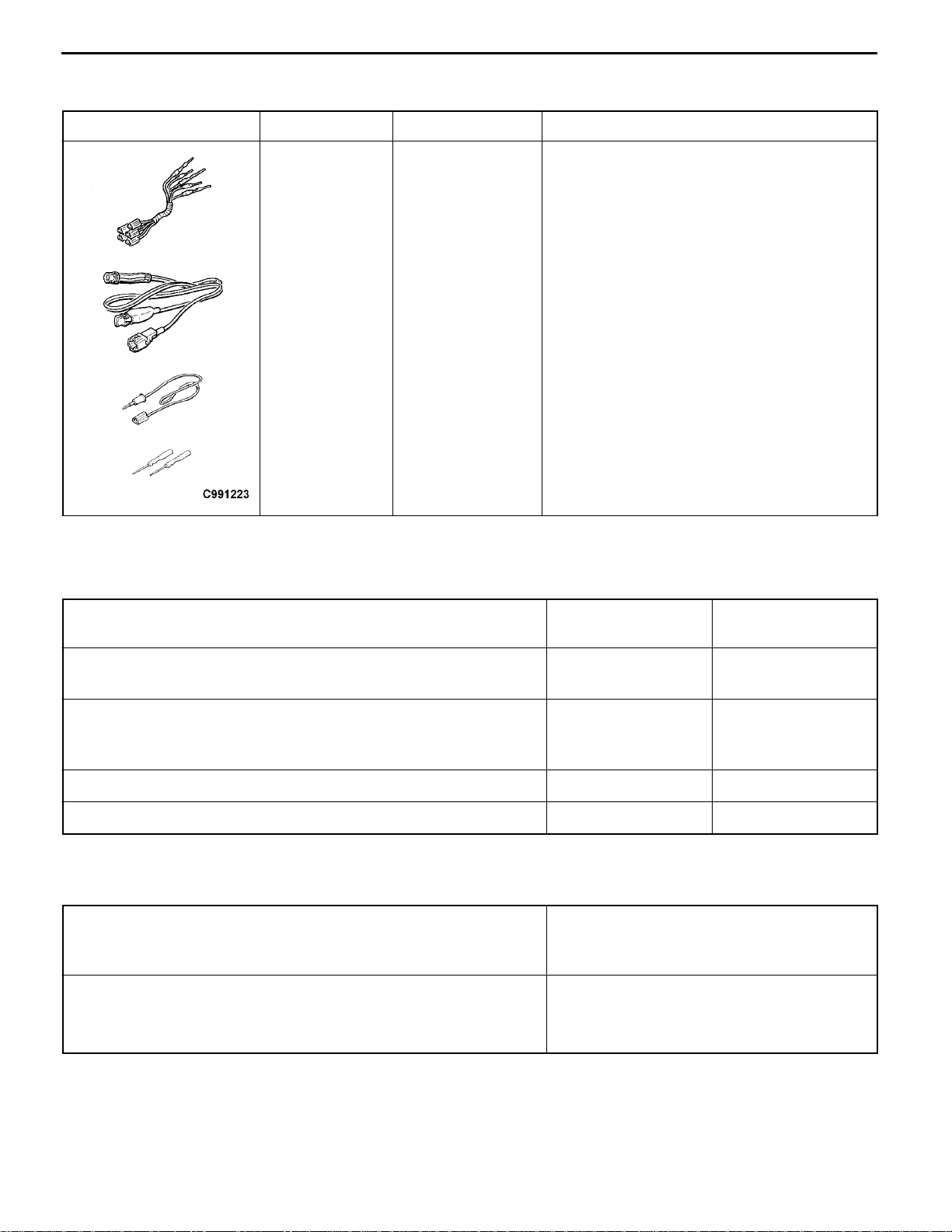
SPECIAL TOOL
Tool Number Name Use
A
MB991223
A: MB991219
B: MB991220
C: MB991221
D: MB991222
B
C
D
Harness set
A: Test harness
B: LED harness
C: LED harness
adapter
D: probe
14100060038
Measurement of terminal voltage
A: Connector pin contact pressure inspection
B: Power circuit inspection
C: Power circuit inspection
D: Commercial tester connection
TROUBLESHOOTING
INSPECTION CHART FOR TROUBLE SYMPTOMS
Trouble symptoms Inspection procedure
No.
Radiator fan and condenser fan do not operate. <Vehicles with A/C>
Radiator fan does not operate. <Vehicles without A/C>
Radiator fan and condenser fan do not change speed or stop.
<Vehicles with A/C>
Radiator fan does not change speed or stop. <Vehicles without A/C>
Radiator fan does not operate. <Vehicles with A/C> 3 14-7
Condenser fan does not operate. <Vehicles with A/C> 4 14-7
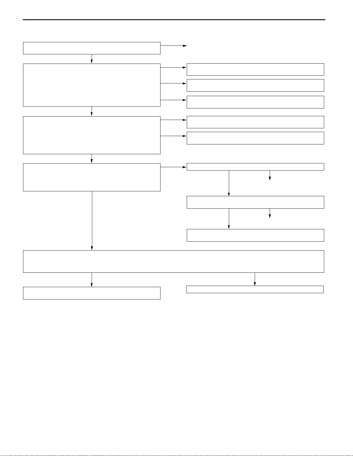
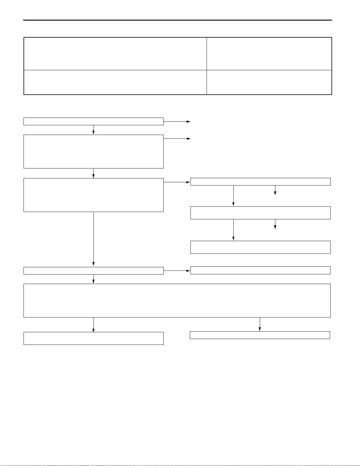
INSPECTION PROCEDURE FOR TROUBLE SYMPTOMS
Inspection Procedure 1
Radiator fan and condenser fan do not operate.
<Vehicles with A/C>
Radiator fan does not operate. <Vehicles without A/C>
The cause could be a malfunction of the fan controller power supply or earth circuit.
The cause could also be a malfunction of the fan controller or the engine-ECU.
1 14-3
2 14-6
Probable cause
Malfunction of fusible link
D
Malfunction of fan control relay
D
Malfunction of fan controller
D
Malfunction of engine-ECU
D
Malfunction of wiring harness or connector
D
14100560019
Reference page
Page 4
14-4
<Vehicles with A/C>
ENGINE COOLING -
Troubleshooting
D Fusible link (7) check
D Fan control relay check (Refer to P.14-11.)
OK
Measure at the fan control relay connector A-20X.
D Remove the relay, and measure at the harness side connector.
(1) Voltage between 4 and body earth
OK:
(2) Voltage between 3 and body earth (Ignition switch: ON)
(3) Continuity between 1 and body earth
Measure at the fan controller connector A-37.
D Disconnect the connector, and measure at the harness side
(1).Voltage between 3 and body earth (Ignition switch: ON)
(2).Continuity between 1 and body earth
Measure at the engine-ECU connector B - 54.
D Connect the connector.
D Voltage between 21 and body earth
Battery voltage
OK:
Battery voltage
OK:
Continuity
OK
connector.
OK:
Battery voltage
OK:
Continuity
OK
(Engine: idling, A/C switch: ON)
OK:
0.7 V or more (When A/C compressor is operating)
OK
NG
(1) NG
(2) NG
(3) NG
(1) NG
(2) NG
NG
Replace
Check the harness wire between fan control relay and fusible link
(7), and repair if necessary.
Check the harness wire between fan control relay and engine control
relay, and repair if necessary.
Check the harness wire between fan control relay and body earth,
and repair if necessary.
Check the harness wire between fan controller and fan control
relay, and repair if necessary.
Check the harness wire between fan controller and body earth,
and repair if necessary.
Check the harness wire between fan controller and engine-ECU.
OK
Engine-ECU terminal voltage check (Refer to GROUP 13 - Troubleshooting.)
OK
NG
Repair
NG
Replace
Measure at the engine-ECU connector B - 54.
D Connect the connector.
D Pull out the terminal No.21 to disconnect it (Ignition switch: ON)
OK:
The radiator fan motor and condenser fan motor operate.
YES
Engine-ECU terminal voltage check (Refer to GROUP 13 - Troubleshooting.)
Check the automatic compressor-ECU, and repair if necessary.
(Refer to GROUP 55 - Troubleshooting.)
NO
Replace the radiator fan motor and fan controller assembly.
Page 5
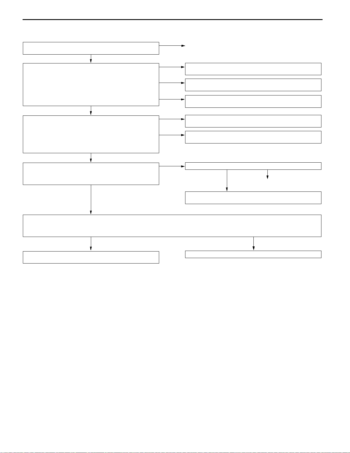
<Vehicles without A/C>
ENGINE COOLING -
Troubleshooting
14-5
D Fusible link (7) check
D Fan control relay check (Refer to P.14-11.)
OK
Measure at the fan control relay connector A-20X.
D Remove the relay, and measure at the harness side connector.
(1) Voltage between 4 and body earth
OK:
(2) Voltage between 3 and body earth (Ignition switch: ON)
(3) Continuity between 1 and body earth
Measure at the fan controller connector A-37.
D Disconnect the connector, and measure at the harness side
(1) Voltage between 3 and body earth (Ignition switch: ON)
(2) Continuity between 1 and body earth
Measure at the engine-ECU connector B-54.
D Connect the connector.
D Voltage between 21 and body earth (Engine: idling)
Battery voltage
OK:
Battery voltage
OK:
Continuity
OK
connector.
OK:
Battery voltage
OK:
Continuity
OK
OK:
0.7 V or more (When radiator fan is operating)
OK
NG
(1) NG
(2) NG
(3) NG
(1) NG
(2) NG
NG
Replace
Check the harness wire between fan control relay and fusible link
(7), and repair if necessary.
Check the harness wire between fan control relay and engine control
relay, and repair if necessary.
Check the harness wire between fan control relay and body earth,
and repair if necessary.
Check the harness wire between fan controller and fan control
relay, and repair if necessary.
Check the harness wire between fan controller and body earth,
and repair if necessary.
Check the harness wire between fan controller and engine-ECU.
OK
Engine-ECU terminal voltage check (Refer to GROUP 13 - Troubleshooting.)
NG
Repair
Measure at the engine-ECU connector B-54.
D Connect the connector.
D Pull out the terminal No.21 to disconnect it (Ignition switch: ON)
OK:
The radiator fan motor operates.
YES
Engine-ECU terminal voltage check (Refer to GROUP 13 - Troubleshooting.)
NO
Replace the radiator fan motor and fan controller assembly.
Page 6
14-6
Inspection Procedure 2
ENGINE COOLING -
Troubleshooting
Radiator fan and condenser fan do not change speed or
stop. <Vehicles with A/C>
Radiator fan does not change speed or stop.
<Vehicles without A/C>
The fan controller carries outstep-free control of the radiator fan motor and the condenser
fan motor speeds using signals transmitted from the engine-ECU.
<Vehicles with A/C>
Fan control relay check (Refer to P.14-11.)
OK
D Check the harness wire between fan control relay and engine
control relay.
D Check the harness wire between fan control relay and body
earth.
D Check the harness wire between fan control relay and fan
controller.
OK
Measure at the engine-ECU connector B-54.
D Connect the connector.
D Voltage between 21 and body earth
(Engine: idling, engine coolant temperature: 80_C or less)
OK:
0 - 0.3 V (Engine: idling, A/C switch: ON)
OK:
0.7 V or more (When A/C compressor is operating)
OK
NG
NG
NG
Probable cause
D Malfunction of fan control relay
D Malfunction of fan controller
D Malfunction of engine-ECU
D Malfunction of wiring harness or connector
Replace
Repair
Check the harness wire between fan controller and engine-ECU.
NG
OK
Engine-ECU terminal voltage check (Refer to GROUP 13 - Troubleshooting.)
OK
Repair
NG
Replace
Fan controller check (Refer to P.14-10.)
OK
Measure at the engine-ECU connector B-54.
D Connect the connector.
D Pull out the terminal No.21 to disconnect it (Ignition switch: ON)
OK:
D Connect the terminal No.21 to the body earth (Ignition switch: ON)
Engine-ECU terminal voltage check (Refer to GROUP 13 - Troubleshooting.)
The radiator fan motor and condenser fan motor operate.
OK:
The radiator fan motor and condenser fan motor stop.
YES
NG
Check the automatic compressor-ECU, and repair if necessary.
(Refer to GROUP 55 - Troubleshooting.)
Replace the radiator fan motor and fan controller assembly.
NO
Replace the radiator fan motor and fan controller assembly.
Page 7

<Vehicles without A/C>
ENGINE COOLING -
Troubleshooting
14-7
Fan control relay check (Refer to P.14-11.)
OK
D Check the harness wire between fan control relay and engine
control relay.
D Check the harness wire between fan control relay and body
earth.
D Check the harness wire between fan control relay and fan
controller.
OK
Measure at the engine-ECU connector B-54.
D Connect the connector.
D Voltage between 21 and body earth
(Engine: idling, engine coolant temperature: 80_C or less)
OK:
0 - 0.3 V (Engine: idling)
OK:
0.7 V or more (When radiator fan is operating)
OK
Fan controller check (Refer to P.14-10.)
OK
Measure at the engine-ECU connector B-54.
D Connect the connector.
D Pull out the terminal No.21 to disconnect it (Ignition switch: ON)
OK:
D Connect the terminal No.21 to the body earth (Ignition switch: ON)
The radiator fan motor operates.
OK:
The radiator fan motor stops.
YES
NG
NG
NG
NG
Replace
Repair
Check the harness wire between fan controller and engine-ECU.
OK NG
Repair
Engine-ECU terminal voltage check (Refer to GROUP 13 - Troubleshooting.)
Replace the radiator fan motor and fan controller assembly.
NO
Engine-ECU terminal voltage check (Refer to GROUP 13 - Troubleshooting.)
Replace the radiator fan motor and fan controller assembly.
Inspection Procedure 3
Radiator fan does not operate. <Vehicles with A/C>
The cause could be a malfunction of the radiator fan motor or an open circuit between
the fan controller and the radiator fan motor.
Replace the radiator fan motor and fan controller assembly.
Probable cause
D Malfunction of radiator fan motor
D Open circuit between fan controller and radiator fan
motor
Inspection Procedure 4
Condenser fan does not operate. <Vehicles with A/C>
The cause could be a malfunction of the condenser fan motor or of the fan controller. D Malfunction of condenser fan motor
Condenser fan motor check (Refer to
GROUP 55.)
OK
Replace the radiator fan motor and fan
controller assembly.
NG
Condenser fan motor connector
OK
Check the trouble symptom.
Probable cause
D Malfunction of fan controller
D Malfunction of wiring harness or connector
NG
NG
Repair
Replace the condenser fan motor.
Page 8

14-8
ENGINE COOLING -
On-vehicle Service
Cap adapter
Adapter
Cap adapter
ON-VEHICLE SERVICE
14100100136
ENGINE COOLANT LEAK CHECKING
1. Confirm that the coolant level is up to the filler neck.
Install a radiator cap tester and apply 160 kPa pressure,
and then check for leakage from the radiator hose or
connections.
Caution
(1) Be sure to completely clean away any moisture
from the places checked.
(2) When the tester is taken out, be careful not to
spill any coolant from it.
(3) Becareful, when installingand removingthe tester
and when testing, not to deform the filler neck
of the radiator.
2. If there is leakage, repair or replace the appropriate part.
RADIATOR CAP OPENING PRESSURE CHECK
14100130159
1. Use a cap adapter to attach the cap to the tester.
2. Increase the pressure until the indicator of the gauge
stops moving.
Limit: 64 kPa
Standard value: 74 - 103 kPa
3. Replace the radiator cap if the reading does not remain
at or above the limit.
NOTE
Be sure that the cap is clean before testing, since rust
or other foreign material on the cap seal will cause an
improper indication.
Page 9

ENGINE COOLING -
ENGINE COOLING -
On-vehicle Service
On-vehicle Service
14-9
<4G6>
<4G9>
<4G6> <4G9>
ENGINE COOLANT REPLACEMENT
14100120231
1. Drain the engine coolant by removing the drain plug and
then the radiator cap.
2. Remove the drain plug from the cylinder block to drain
the engine coolant.
3. Remove the reserve tank to drain the engine coolant.
4. When the engine coolant has drained, pour in water from
the radiator cap to clean the engine coolant line.
5. Coat the thread of the cylinder block drain plug with the
specified sealant and tighten to the specified torque.
44 Nm
Specified sealant:
3M Nut Locking Part No. 4171 or equivalent
6. Securely tighten the radiator drain plug.
7. Install the reserve tank.
39 Nm
8. Slowly pour the engine coolant into the mouth of the
radiator until the radiator is full, and pour also into the
reserve tank up to the FULL line.
Recommended antifreeze:
MITSUBISHI GENUINE COOLANT or equivalent
Quantity:
<4G6> 7 L
<4G9> 6 L
Caution
Do not use alcohol or methanol anti-freeze or any
engine coolants mixed with alcohol or methanol
anti-freeze. The use of an improper anti-freeze can
cause the corrosion of the aluminium components.
NOTE
For Norway, the non-amine type of antifreeze should be
used.
9. Install the radiator cap securely.
Page 10

14-10
ENGINE COOLING -
10. Start the engine and warm the engine until the thermostat
opens. (Touch the radiator hose with your hand to check
that warm water is flowing.)
11. After the thermostat opens, race the engine several times,
and then stop the engine.
12. Cool down the engine, and then pour engine coolant
into the reserve tank until the level reaches the FULL
line. If the level is low, repeat the operation from step
9.
On-vehicle Service
Fan controller
CONCENTRATION MEASUREMENT
14100110146
Measure the temperature and specific gravity of the engine
coolant to check the antifreeze concentration.
Standard value: 30 - 60 %(allowable concentration range)
RECOMMENDED ANTIFREEZE
Antifreeze Allowable concentration
MITSUBISHI GENUINE COOLANT
or equivalent
30 - 60 %
Caution
If the concentration of the antifreeze is below 30 %, the
anti-corrosion property will be adversely affected. In
addition, if the concentration is above 60 %, both the
anti-freezing and engine cooling properties will decrease,
affecting the engine adversely. For these reasons, be
sure to maintain the concentration level within the
specified range.
FAN CONTROLLER CHECK
14100610011
1. Remove the fan controller mounting bolt, and then
disconnect the condenser fan motor connector.
2. Start the engine and run it at idle.
3. Turn the A/C switch to ON and maintain the coolant
temperature at 80_C or less.
4. When measuring the voltage between the fan
controller-side connector terminals, check that the value
changes repeatedly as indicated by (1) - (3) below.
(1) 0 V
(2) 8.2 ± 2.6 V
(3) Battery voltage ± 2.6 V
5. If the voltage does not repeatedly change as indicated,
replace the radiator fan motor and the fan controller
assembly.
Page 11

ENGINE COOLING -
FAN CONTROL RELAY CONTINUITY CHECK
Battery voltage Terminal No.
When current is not
Fan control relay
supplied
When current is
supplied
On-vehicle Service
1 2 3 4
14-11
14100620014
Page 12

14-12
ENGINE COOLING -
Thermostat
THERMOSTAT
REMOVAL AND INSTALLATION
Pre-removal and Post-installation Operation
D Engine Coolant Draining and Supplying (Refer to
P.14-9.)
D Air Intake Duct Removal and Installation
<4G6>
14100240265
3
2
1
<4G9>
13 Nm
3
2
13 Nm
1
AA""BA
Removal steps
1. Radiator lower hose connection
2. Water inlet fitting
"AA
3. Thermostat
Page 13

Rubber ring
ENGINE COOLING -
Jiggle valve
Thermostat
14-13
REMOVAL SERVICE POINT
AA"
After making mating marks on the radiator hose and the hose
clamp, disconnect the radiator hose.
RADIATOR LOWER HOSE DISCONNECTION
INSTALLATION SERVICE POINTS
"AA
Install the thermostat so that the jiggle valve is facing straight
up.
Caution
Make absolutely sure that no oil is adhering to the rubber
ring of the thermostat. In addition, be careful not to fold
over or scratch the rubber ring when inserting. If the
rubber ring is damaged, replace the thermostat.
THERMOSTAT INSTALLATION
"BA
1. Insert each hose as far as the projection of the water
2. Align the mating marks on the radiator hose and hose
INSPECTION
THERMOSTAT CHECK
1. Immerse the thermostat in water, and heat the water while
2. Check that the amount of valve lift is at the standard
RADIATOR LOWER HOSE CONNECTION
inlet fitting.
clamp, and then connect the radiator hose.
14100250275
stirring. Check the thermostat valve opening temperature.
Standard value:
Valve opening temperature: 85±1.5_C
value when the water is at the full-opening temperature.
Valve lift
Standard value:
Full-opening temperature: 98_C
Amount of valve lift: 8.5 mm or more
NOTE
Measure the valve height when the thermostat is fully
closed, and use this measurement to calculate the valve
height when the thermostat is fully open.
Page 14

14-14
ENGINE COOLING -
Water Pump <4G6>
WATER PUMP <4G6>
REMOVAL AND INSTALLATION
Pre-removal and Post-installation Operation
D Engine Coolant Draining and Supplying
(Refer to P.14-9.)
D Engine Cover Removal
D Timing Belt Removal a nd Installation (Refer to
GROUP 11A.)
4
2
1
14100270363
24 Nm
Removal steps
1. Alternator brace
2. Water pump
"AA
Water inlet pipe assembly
3. Water pump gasket
4. O-ring
Water pump
13 Nm
O-ring
Bolt specifications
8 ´ 80
3
8 ´ 14
2
8 ´ 25
8 ´ 22
Screw diameter ´ length mm
INSTALLATION SERVICE POINT
"AA
Insert the O-ring to the water inlet pipe assembly, and coat
the outer circumference of the O-ring with water or engine
coolant.
Caution
Do not allow engine oil or other greases to adhere to
the O-ring
O-RING INSTALLATION
Page 15

ENGINE COOLING -
Water Pump <4G9>
14-15
WATER PUMP <4G9>
REMOVAL AND INSTALLATION
Pre-removal and Post-installation Operation
D Engine Coolant Draining and Supplying
(Refer to P.14-9.)
D Timing Belt Removal and Installation
(Refer to GROUP 11B.)
1
14100270370
D Idler Pulley Removal and Installation
(Refer to GROUP 11B - Timing Belt.)
10 - 12 Nm
"AA
24 Nm
2
Removal steps
1. Timing belt rear left cover
2. Water pump
Sealant:
Mitsubishi Genuine Part No.
MD970389 or equivalent
INSTALLATION SERVICE POINT
"AA
Squeeze out the sealant from the tube evenly and apply
it so that there is not too much sealant and no places without
sealant.
Specified Sealant:
WATER PUMP INSTALLATION
Mitsubishi Genuine Part No. MD970389 or equivalent
Page 16

14-16
ENGINE COOLING -
Water Hose and Water Pipe
WATER HOSE AND WATER PIPE
REMOVAL AND INSTALLATION
<4G6>
Pre-removal and Post-installation Operation
D Engine Coolant Draining and Supplying
(Refer to P.14-9.)
1
13 Nm
7
2
6
14100330306
D Engine Cover Removal and Installation
D Air Cleaner Assembly Removal and Installation
24 Nm
9
8
Sealant:
Mitsubishi Genuine Part No.
MD970389 or equivalent
3
5
4
9
10
13 Nm
AA""CA
AA""CA
Removal steps
1. Radiator upper hose connection
2. Radiator lower hose connection
3. Water hose
4. Water hose
5. Water hose
"BA
"AA
6. Water inlet fitting
7. Thermostat case assembly
8. Heater hose connection
9. O-ring
10. Water inlet pipe
Page 17

ENGINE COOLING -
<4G9>
Pre-removal and Post-installation Operation
D Engine Coolant Draining and Suppling
(Refer to P.14-9.)
D Engine Cover Removal and Installation
D Air Cleaner Assembly and Air Intake Hose Removal
and Installation
Water Hose and Water Pipe
14-17
6
5
2
22 - 25 Nm
3
14 Nm
6
4
6
1
14 Nm
7
8
AA""CA
"BA
"AA
Removal steps
1. Radiator lower hose connection
2. Water temperature gauge unit
connector
3. Thermostat case assembly
4. O-ring
5. Heater hose connection
Sealant:
"AA
Mitsubishi Genuine Part No.
MD970389 or equivalent
D
Intake manihold
(Refer to GROUP 15)
6. Water hose
7. Water inlet pipe assembly
8. O-ring
Page 18

14-18
ENGINE COOLING -
REMOVAL SERVICE POINT
AA"
After making mating marks on the radiator hose and the hose
clamp, disconnect the radiator hose.
Water Hose and Water Pipe
RADIATOR UPPER HOSE/RADIATOR LOWER
HOSE DISCONNECTION
Thermostat case assembly,
water pump or cylinder block
O-ring
Water inlet pipe assembly or
heater pipe assembly
INSTALLATION SERVICE POINTS
"AA
Insert the O-ring to the water inlet pipe assembly or the heater
pipe assembly and coat the outer circumference of the O-ring
with water or engine coolant.
Caution
Do not allow engine oil or other greases to adhere to
the O-ring
"BA
Squeeze out the sealant from the tube evenly and apply
it so that there is not too much sealant and no places without
sealant.
Specified Sealant:
"CA
1. Insert each hose as far as the projection of the water
2. Align the mating marks on the radiator hose and hose
O-RING INSTALLATION
THERMOSTAT CASE ASSEMBLY INSTALLATION
Mitsubishi Genuine Parts No. MD970389 or equivalent
RADIATOR LOWER HOSE/RADIATOR UPPER
HOSE CONNECTION
inlet fitting or water outlet fitting.
clamp, and then connect the radiator hose.
INSPECTION
14100340118
WATER PIPE AND HOSE CHECK
Check the water pipe and hose for cracks, damage, clog
and replace them if necessary.
Page 19

ENGINE COOLING -
Radiator
14-19
RADIATOR
REMOVAL AND INSTALLATION
Pre-removal operation
D Engine Coolant Draining (Refer to P.14-9.)
D Air Intake Duct Assembly Removal
D Battery and Battery Cover Removal
12 Nm
9
2
3
9
5
10
Post-installation Operation
D Air Intake Duct Assembly Installation
D Engine Coolant Supplying (Refer to P.14-9.)
D A/T Fluid Supplying and Checking
(Refer to GROUP 23 - On-vehicle Service.)
D Battery and Battery Cover Installation
14
15
17
16
14100150285
4
AA""AA
AA""AA
AB"
1
7
11
11
6
Radiator removal steps
1. Drain plug
2. Radiator cap
3. Overflow hose
4. Reserve tank
5. Radiator upper hose
6. Radiator lower hose
7. Transmission fluid cooler hose
connection <A/T>
8. Condenser fan motor assembly
<Vehicle with A/C>
9. Upper insulator
10. Radiator assembly
11. Lower insulator
12. Bolt <A/T>
13
12
5Nm
AB"
AA""AA
8
13. Transmission fluid cooler hose and
pipe assembly <A/T>
14. Radiator fan motor assembly
Radiator fan motor and fan
controller assembly removal steps
5. Radiator upper hose
12. Bolt <A/T>
8. Condenser fan motor assembly
<Vehicle with A/C>
14. Radiator fan motor assembly
15. Fan
16. Radiator fan motor and fan
controller assembly
17. Shroud
Page 20

14-20
ENGINE COOLING -
REMOVAL SERVICE POINTS
AA"
After making mating marks on the radiator hose and the hose
clamp, disconnect the radiator hose.
AB"
After disconnecting the hoses from the radiator and the
transmission, plug all of the pipes and hoses to prevent dirt
and other foreign objects from getting inside.
RADIATOR UPPER HOSE/RADIATOR LOWER
HOSE DISCONNECTION
TRANSMISSION FLUID COOLER HOSE AND PIPE
ASSEMBLY REMOVAL
INSTALLATION SERVICE POINT
"AA
1. Insert each hose as far as the projection of the water
2. Align the mating marks on the radiator hose and hose
RADIATORLOWER HOSE/RADIATORUPPER HOSE
CONNECTION
inlet fitting.
clamp, and then connect the radiator hose.
Radiator
 Loading...