

Page 1

Page 2

MELSEC is registered trademark of Mitsubishi Electric Corporation.
Other company and product names that appear in this manual are trademarks or
registered trademarks of the respective company.
Page 3
Introduction
These specifications are the programming manual used when creating the sequence
program for the EZMotion-NC E60/E68 with the onboard PLC development tool or PLC
development software.
The PLC (Programmable Logic Controller) is largely divided into the basic commands,
function commands and exclusive commands, and ample command types are available.
The commands can be used according to the purpose and application such as the PLC
support function used when supporting the user PLCs.
Details described in this manual
CAUTION
For items described in "Restrictions" or "Usable State", the instruction manual
issued by the machine maker takes precedence over this manual.
Items not described in this manual must be interpreted as "not possible".
This manual is written on the assumption that all option functions are added.
Refer to the specifications issued by the machine maker before starting use.
Refer to the Instruction Manual issued by each machine maker for details in each
machine tool.
Some screens and functions may differ or may not be usable depending on the
NC version.
General precautions
(1) This Instruction Manual does not explain the operation procedures for programming
the sequence program with onboard or personal computer. Refer to the related
material listed below for details.
EZMotion-NC E60/E68 PLC Onboard Instruction Manual ..... IB-1500179(ENG)
EZMotion-NC E60/E68 PLC Interface Manual ..... IB-1500176(ENG)
EZMotion-NC E60/E68 PLC Development Software Manual
(MELSEC Tool Section)
..... IB-1500177(ENG)
Page 4
Precautions for Safety
Always read the specifications issued by the machine maker, this manual, related
manuals and attached documents before installation, operation, programming,
maintenance or inspection to ensure correct use.
Understand this numerical controller, safety items and cautions before using the unit.
This manual ranks the safety precautions into "DANGER", "WARNING" and "CAUTION".
When there is a great risk that the user could be subject to
DANGER
WARNING
CAUTION
Note that even items ranked as " CAUTION", may lead to major results depending
on the situation. In any case, important information that must always be observed is
described.
fatalities or serious injuries if handling is mistaken.
When the user could be subject to fatalities or serious injuries
if handling is mistaken.
When the user could be subject to injuries or when physical
damage could occur if handling is mistaken.
Not applicable in this manual.
Not applicable in this manual.
1. Items related to product and manual
For items described as "Restrictions" or "Usable State" in this manual, the instruction
manual issued by the machine maker takes precedence over this manual.
An effort has been made to describe special handling of this machine, but items that are
not described must be interpreted as "not possible".
This manual is written on the assumption that all option functions are added. Refer to
the specifications issued by the machine maker before starting use.
Refer to the Instruction Manual issued by each machine maker for details on each
machine tool.
Some screens and functions may differ or some functions may not be usable
depending on the NC version.
DANGER
WARNING
CAUTION
2. Items related to start up and maintenance
Read this manual carefully and confirm the safety enough before executing the
operation of the program change, forced output, RUN, STOP, etc. during operation.
Operation mistakes may cause damage of the machine and accidents.
Page 5

CONTENTS
1. System Configuration .................................................................................... 1
1.1 System Configuration for PLC Development ............................................. 1
1.2 User PLC (Ladder) Development Procedure.............................................. 2
2. PLC Processing Program .............................................................................. 3
2.1 PLC Processing Program Level and Operation ......................................... 3
2.2 User Memory Area Configuration .............................................................. 3
3. Input/Output Signals ...................................................................................... 4
3.1 Input/Output Signal Types and Processing ............................................... 4
3.2 Handling of Input Signals Designated for High-Speed Input ..................... 5
3.3 High-Speed Input/output Designation Method ........................................... 6
3.4 Limits for Using High Speed Processing Program ..................................... 7
3.4.1 Separation of Main Processing and High Speed Processing Bit
Operation Areas................................................................................... 7
3.4.2 Separation of Remote I/O Output......................................................... 8
4. Parameters ...................................................................................................... 10
4.1 PLC Constants .......................................................................................... 10
4.2 Bit Selection Parameters ........................................................................... 11
5. Explanation of Devices .................................................................................. 15
5.1 Devices and Device Numbers ................................................................... 15
5.2 Device List ................................................................................................. 15
5.3 Detailed Explanation of Devices ................................................................ 16
5.3.1 Input/output X, Y ................................................................................. 16
5.3.2 Internal Relays M and F, Latch Relay L .............................................. 17
5.3.3 Special Relays SM .............................................................................. 17
5.3.4 Timer T ................................................................................................ 18
5.3.5 Counter C ............................................................................................ 20
5.3.6 Data Register D ................................................................................... 20
5.3.7 File Register R .................................................................................... 21
5.3.8 Index Registers Z ................................................................................ 22
5.3.9 Nesting N ............................................................................................ 23
5.3.10 Pointer P ............................................................................................ 24
5.3.11 Decimal Constant K ............................................................................ 25
5.3.12 Hexadecimal Constant H .................................................................... 25
6. Explanation of Commands ............................................................................ 26
6.1 Command List ........................................................................................... 26
6.1.1 Basic Commands ................................................................................ 26
6.1.2 Function Commands ........................................................................... 27
6.1.3 Exclusive commands ........................................................................... 33
6.2 Command Formats ................................................................................... 34
6.2.1 How to Read the Command Table ...................................................... 34
6.2.2 No. of Steps ........................................................................................ 35
6.2.3 END Command ................................................................................... 36
6.2.4 Index Ornament .................................................................................. 36
6.2.5 Digit Designation ................................................................................. 37
Page 6

7. Basic Commands
(LD, LDI, AND, ANI, OR, ORI, ANB, ORB .....) ............................................... 41
8. Function Commands
(=, >, <, +, –, *, /, BCD, BIN, MOV .....) ............................................................ 73
9. Exclusive Commands .................................................................................... 190
9.1 ATC Exclusive Command ......................................................................... 191
9.1.1 Outline of ATC Control ........................................................................ 191
9.1.2 ATC Operation .................................................................................... 191
9.1.3 Explanation of Terminology ................................................................. 191
9.1.4 Relationship between Tool Registration Screen and Magazines ........ 192
9.1.5 Use of ATC and ROT Commands ....................................................... 193
9.1.6 Basic Format of ATC Exclusive Command ......................................... 194
9.1.7 Command List ..................................................................................... 195
9.1.8 Control Data Buffer Contents .............................................................. 195
9.1.9 File Register (R Register) Assignment and Parameters ...................... 196
9.1.10 Details of Each Command................................................................... 198
9.1.11 Precautions for Using ATC Exclusive Instructions .............................. 207
9.1.12 Examples of Tool Registration Screen ............................................... 207
9.1.13 Display of Spindle Tool and Standby Tool .......................................... 209
9.2 S.ROT Commands .................................................................................... 210
9.2.1 Command List...................................................................................... 210
9.3 Tool Life Management Exclusive Command ............................................. 216
9.3.1 Tool Life Management System ............................................................ 216
9.3.2 Tool Command System ....................................................................... 216
9.3.3 Spare Tool Selection System .............................................................. 217
9.3.4 Interface .............................................................................................. 217
9.3.5 User PLC Processing When the Tool Life Management Function
Is Selected .......................................................................................... 218
9.3.6 Examples of Tool Life Management Screen ........................................ 226
9.4 DDB (Direct Data Bus) ... Asynchronous DDB .......................................... 227
9.4.1 Basic Format of Command .................................................................. 227
9.4.2 Basic Format of Control Data .............................................................. 227
9.5 External Search ......................................................................................... 230
9.5.1 Function .............................................................................................. 230
9.5.2 Interface .............................................................................................. 230
9.5.3 Search Start Instruction ....................................................................... 232
9.5.4 Timing Charts and Error Causes ......................................................... 232
9.5.5 Sequence Program Example .............................................................. 234
9.6 Chopping..................................................................................................... 235
9.6.1 Chopping operation start...................................................................... 236
9.6.2 Chopping operation stop...................................................................... 238
9.6.3 Chopping compensation....................................................................... 239
9.6.4 Chopping interface............................................................................... 242
9.6.5 Parameters (DDB function instructions from PLC)............................... 243
9.6.6 Example of chopping control by program command ............................ 249
Page 7

10. PLC Help Function ......................................................................................... 252
10.1 Alarm Message Display............................................................................ 253
10.1.1 Interface............................................................................................. 253
10.1.2 Screen Display................................................................................... 255
10.1.3 Message Creation.............................................................................. 256
10.1.4 Parameters......................................................................................... 259
10.2 Operator Message Display....................................................................... 261
10.2.1 Interface............................................................................................. 261
10.2.2 Operator Message Preparation.......................................................... 262
10.2.3 Operator Message Display Validity Parameter................................... 262
10.3 PLC Switches........................................................................................... 263
10.3.1 Explanation of Screen........................................................................ 263
10.3.2 Explanation of Operation.................................................................... 264
10.3.3 Signal Processing............................................................................... 265
10.3.4 Switch Name Preparation................................................................... 269
10.4 Key Operation by User PLC..................................................................... 270
10.4.1 Key Data Flow.................................................................................... 270
10.4.2 Key Operations That Can Be Performed............................................ 270
10.4.3 Key Data Processing Timing.............................................................. 271
10.4.4 Layout of Keys on Setting and Display Unit ....................................... 272
10.4.5 List of Key Codes............................................................................... 273
10.5 Load Meter Display .................................................................................. 274
10.5.1 Interface............................................................................................. 274
10.6 External Machine Coordinate System Compensation.............................. 276
10.7 User PLC Version Display........................................................................ 277
10.7.1 Interface............................................................................................. 277
11. PLC Axis Control ........................................................................................... 279
11.1 Outline...................................................................................................... 279
11.2 Specifications........................................................................................... 279
11.2.1 Basic Specifications ........................................................................... 279
11.2.2 Other Restrictions .............................................................................. 280
11.3 PLC Interface........................................................................................... 281
11.3.1 S.DDBS Function Command.............................................................. 281
11.3.2 Control Information Data.................................................................... 282
11.3.3 Control Information Data Details ........................................................ 283
11.3.3.1 Commands................................................................................ 283
11.3.3.2 Status ........................................................................................ 284
11.3.3.3 Alarm No.................................................................................... 291
11.3.3.4 Control Signals (PLC axis control information data) .................. 292
11.3.3.5 Axis Designation........................................................................ 294
11.3.3.6 Operation Mode......................................................................... 294
11.3.3.7 Feedrate.................................................................................... 295
11.3.3.8 Movement Data......................................................................... 295
11.3.3.9 Machine Position ....................................................................... 296
11.3.3.10 Remaining Distance.................................................................. 296
11.3.4 Reference Point Return Near Point Detection.................................... 297
11.3.5 Handle Feed Axis Selection ............................................................... 298
12. Appendix ....................................................................................................... 299
12.1 Example of Faulty Circuit ......................................................................... 299
Page 8
r
1. System Configuration
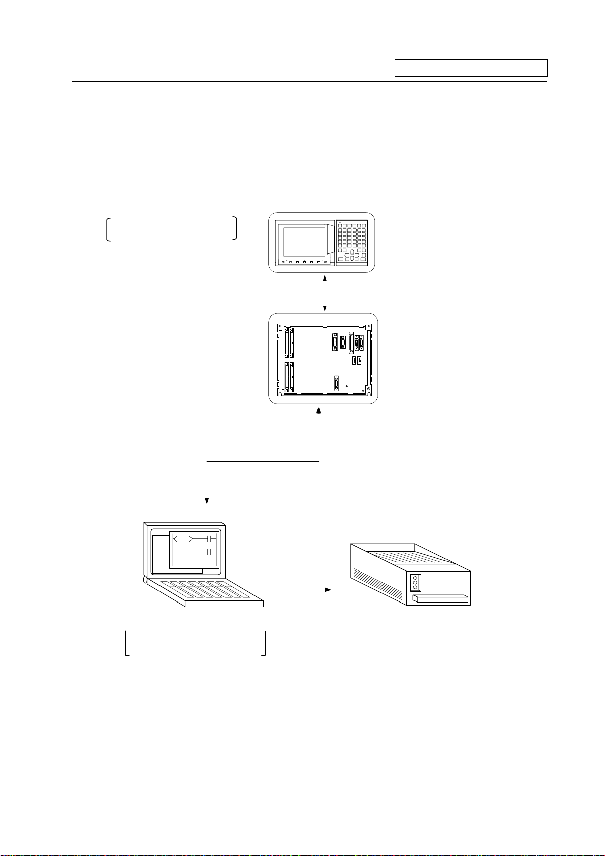
1.1 System Configuration for PLC Development
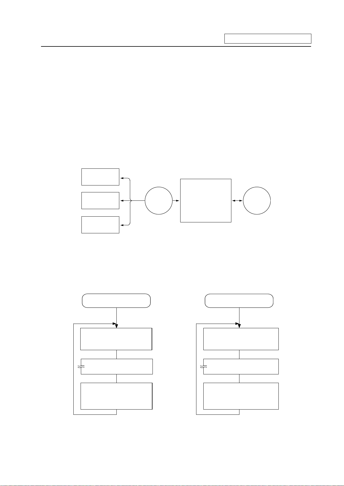
The system configuration for PLC development is shown below.
1. System Configuration
Ladder editing, ladder monitor
and PLC RUN/STOP, etc.
A new development is possible
with the personal computer.
Setting and Display Unit
Setting andDisplayUnit
Base I/O Unit
Base I/O Unit
To connector RS-232C
RS-232C
Up/downloading is carried out with
the personal computer's development
tool.
The ladder is developed using
the setting and display unit.
(Onboard development)
Personal computer
Used for ladder development,
creating message, ladder monitor
and saving data.
General printe
(Note) Refer to the "PLC Onboard Instruction Manual" (IB-1500179) for edition using the setting and
display unit (onboard edition), and the "PLC Development Software Manual (MELSEC Tool
Section)" (IB-1500177) for development using the personal computer.
- 1 -
Page 9
1. System Configuration
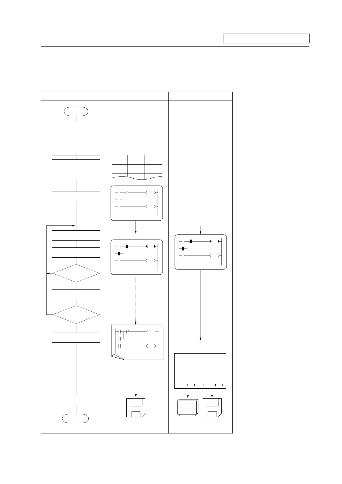
1.2 User PLC (Ladder) Development Procedure
The procedure for creating the user PLC, used to control the control target (machine) built into the
control unit, is shown below.
Procedure Personal Computer CNC Unit
Start
Determinat ion of
machine
Determinat ion of
CNC and PLC
specific at ion s
Determination of th e
num ber s of I /O points
Assi gn m e n t of I/O
signals
Assignment of
internal relays
Programming
Comm erci ally avai lable
spre adsh eet too l
Device Name
X0 X -O T X-axis OT
X1 Y-OT Y-axis OT
X2 Z -O T Z- axis O T
GX Developer
Comment
The data created with the
commercially available
spreadsheet tool can be
used as ladder comment
data.
Use GX Developer for
programming.
After completion, download
the data through RS-232C.
Debug gi n g operation
Program correction
Is debugging
complete?
NO
Test op era ti on by
CNC unit
Is test operation
NO
OK?
YES
Printout
YES
GX Developer
GX Developer
Onboard
BACKUP s cr een
DATA IN/OUT screen
[BACKUP]
#1 BACKUP #######
#2 RESTORE #########
#( ) ( )
PARAM 3.2 / 2
Perform monitoring/correction
with GX Developer's online
function or onboard function.
Printout to a commercial
printer connected with the
personal computer from GX
Developer.
Excute the ROM backup
operation on the BACKUP
screen.
Excute the binary data output
on the DATA IN/OUT screen.
Data save
Comp let i on
Program dat a
Memory cassette
(F-ROM)
- 2 -
Binary data
Program data:
Saved using GX Developer
Binary data:
Saved using DATA IN/OUT
screen
Page 10
2. PLC Processing Program
2. PLC Processing Program
2.1 PLC Processing Program Level and Operation
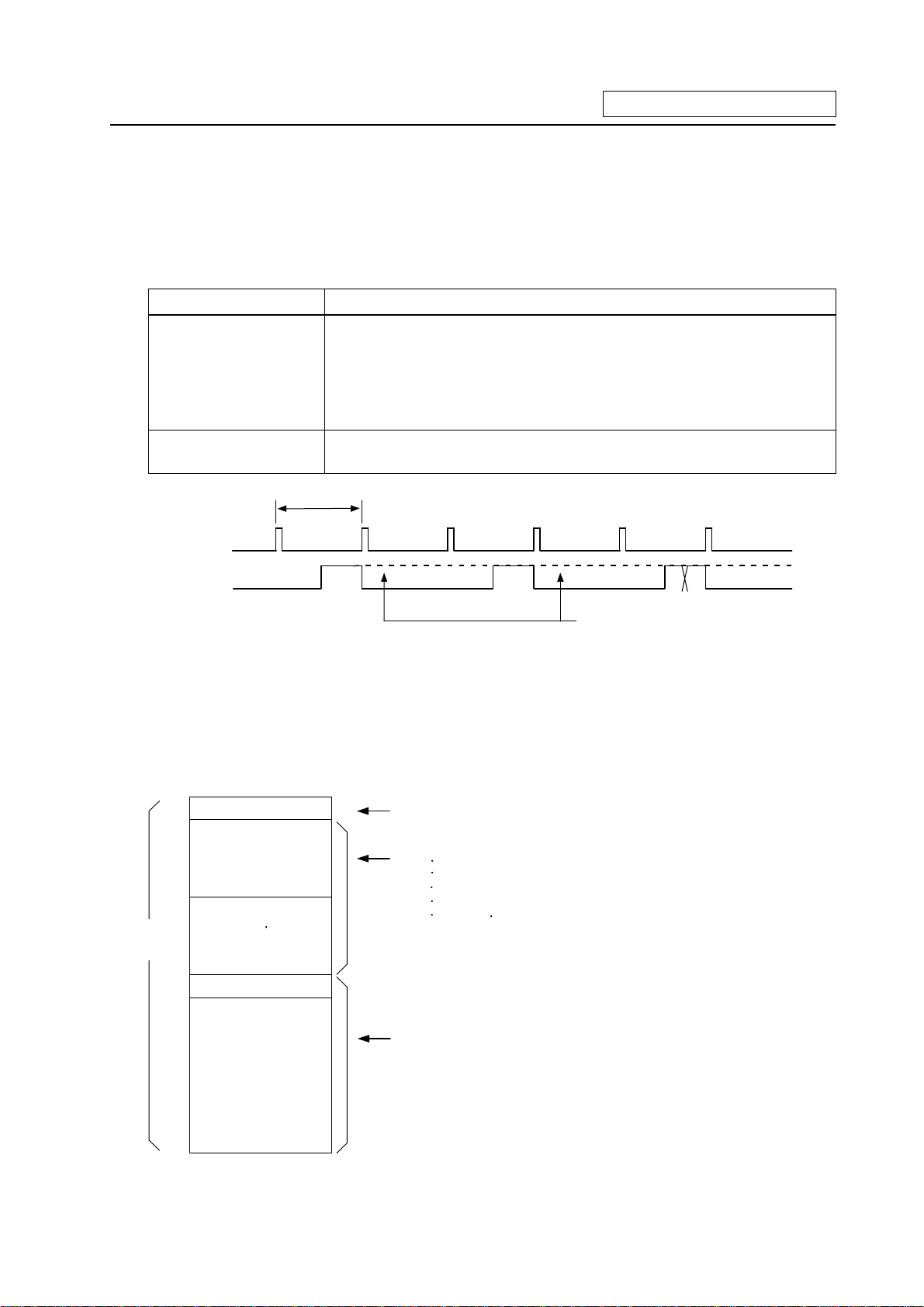
Table 2.1-1 explains the contents of users PLC processing level and Fig. 2.1-1 shows the timing chart.
Table 2.1-1 PLC processing level
Program name Description (frequency, level, etc.)
High-speed processing
program
Main processing
program (ladder)
This program starts periodically with a time interval of 7.1ms.
This program has the highest level as a program that starts periodically.
It is used in signal processing where high-speed processing is required.
Processing time of this program shall not exceed 0.5ms.
Application example:
Position count control of turret and ATC magazine
This program runs constantly. When one ladder has been executed from
the head to END, the cycle starts again at the head.
7.1ms
High-speed
processing
Main processing
This section is used by the controller.
(Note 1)
(Note 1) The section from the END command to the next scan is done immediately as shown with
the X section. Note that the min. scan time will be 14.2ms.
Fig. 2.1-1 PLC processing program operation timing chart
2.2 User Memory Area Configuration
The user memory area approximate configuration and size are shown below.
User PL C
code ar ea
P251
P252
Control information
Message data
Contact coil
comment data
High-speed processing
Internal information table of User PLC
(The table is automatically generated.)
Data excepting the ladder program
Alarm messages
Operator messages
PLC switches
Load meter
Contact coil comment data, etc.
(Each of them can be stored in two languages.)
Total 127Kbyte
Program with the ladder language
Programs excepting the main processing are
Main Processing
Max. 256Kbyte from control
information to messages.
not necessary.
The program order of initial, high-speed and main
processing is random.
Total 4000 steps
- 3 -
Page 11
3. Input/Output Signals
3. Input/Output Signals
3.1 Input/Output Signal Types and Processing
The input/output signals handled in user PLC are as follows:
(1) Input/output from/to controller
(2) Input/output from/to operation board (Note 1)
(3) Input/output from/to machine
The user PLC does not directly input or output these signals from or to hardware or controller; it inputs
or outputs the signals from or to input/output image memory. For the reading and writing with the
hardware or controller, the controller will perform the input/output according to the level of the main
process or high-speed process.
Controller
Operation
board
Machine
Controller
Input/output image
memory
(device X, Y)
User PLC
(Note 1) The operation board here refers to when the remote I/O unit is installed on the communication
terminal.
Fig. 3.1-1 Concept of input/output processing
High-speed processing
input/output
The con troller reads th e
high-s peed in pu t
designation input, and
sets in the image memory.
User PLC high-speed
proces sin g
Main processing
input/output
The controller reads the
input other than th e h igh-speed
input designation,
and s ets in the im age memor y.
P252P251
User PLC main
proces sin g
The con tr oller outputs
the high-speed output
design ation output from
the im age m emory to the
machine.
Fig. 3.1-2 Input/output processing conforming to program level
- 4 -
The controller outputs
the output other than the
high-speed output
designation f rom the
ima g e memory to the m a c h i n e.
Page 12
3. Input/Output Signals
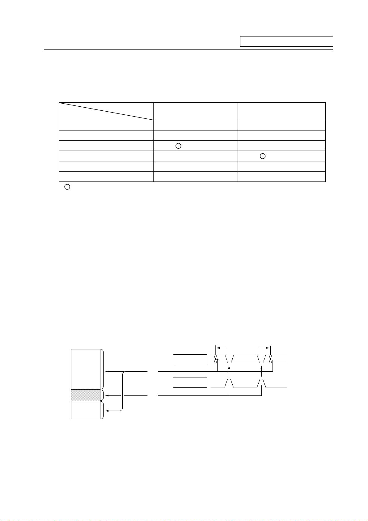
Table 3.1-1 lists whether or not high-speed input/output, interrupt input and initial processing can be
performed.
Table 3.1-1 Whether or not high-speed input/output, interrupt input and initial
can be performed
High-speed input
specification
Input signal from control unit
Output signal to control unit
Input signal from machine
Output signal to machine
Input signal from operation board
Output signal to operation board
x x
x x
(2-byte units) x
x
x x
x x
: Possible x : Not possible
The operation board in Table 3.1-1 is applied when control is performed by operation board
input/output card that can be added as NC option.
High-speed output
specification
(2-byte units)
3.2 Handling of Input Signals Designated for High-Speed Input
The input/output signals used in user PLC are input/output for each program level as shown in
Fig. 3.1-2.
In high-speed processing, input/output signal for which high-speed input or output designation
(parameter) is made is input or output each time the high-speed processing program runs. In main
processing, signals other than interrupt input signals or high-speed input/output designation are
input/output.
When high-speed input designation signal is used in main processing, the input signal may change
within one scan because high-speed processing whose level is higher than main processing
interrupts. Input signal which must not change within one scan should be saved in temporary memory
(M), etc., at the head of main processing and the temporary memory should be used in the main
program, for example.
Input im age memory
Main
processing
(1)
High-speed
processing
(2)
(1) Set at th e h ead of mai n p r ocessin g.
PLC on e s c an
A B
A
(2) S e t at t h e h e ad of high -speed pr oc e ss i n g.
The hatched area is high-speed input designation part. Whenever the high-speed processing
program runs, data is reset in the hatched area. Thus, the signal in the hatched area may change in
main processing (A) and (B) because the high-speed process interrupts between (A) and (B) and
re-reads the input signal in the hatched area.
- 5 -
Page 13
3. Input/Output Signals
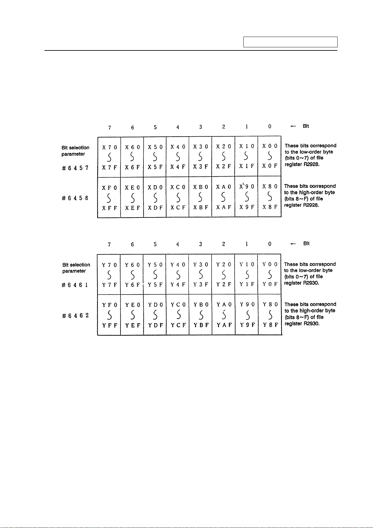
3.3 High-Speed Input/output Designation Method
High-speed input/output is designated by setting the corresponding bit of the bit selection parameter
as shown below.
(1) High-speed input designation
(2) High-speed output designation
· As listed above, one bit corresponds to two bytes (16 points).
· Input or output in which 1 is set in the table is not performed at the main processing program
level.
· Although the number of bits set to 1 is not limited, set only necessary ones from viewpoint of
overhead.
· High-speed input/output designation corresponds to the bit selection parameter and can be
set in the parameter. However, it is recommended to set in a sequence program to prevent a
parameter setting error, etc.
Example: —[MOV H3 R2928]— ..... To designate X00~X0F, X10~X1F (bit 0 and 1 for H3)
- 6 -
Page 14
3. Input/Output Signals
3.4 Limits for Using High Speed Processing Program
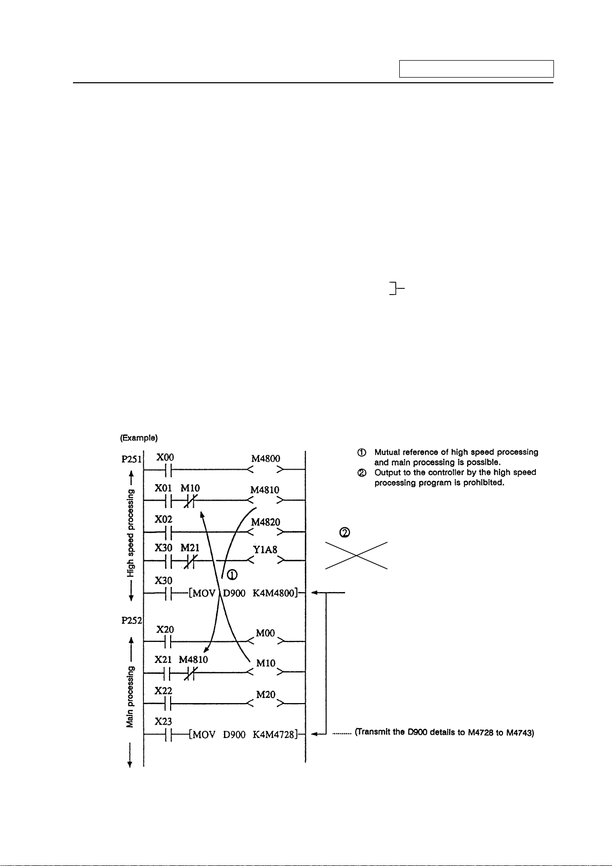
3.4.1 Separation of Main Processing and High Speed Processing Bit Operation Areas
(1) Bit operation area
When using high speed processing, the bit operation range such as the temporary memory is
separated from the main process.
(Method 1) When using the same M or G code, the bit operation area for high speed processing
and the bit operation area for main processing are separated by 64 points or more
and used.
For example, the following is used
M0 to M4735 for main processing Separate by 64 points or more
M4800 to M5120 for high speed processing (M4736 to M4799 are not used)
(Method 2) M is used for the main processing temporary memory and G is used for the high
speed processing temporary memory.
(Note 1) The output devices handled with high speed processing must be limited to M or Y, D
and R.
(Note 2) These limits apply not only to the OUT command, but also to the PLF, PLS, SET, RST
and MOV command, etc., outputs. The devices apply to all devices including M, F, L,
SM, T and C.
- 7 -
Interlock
Output to NC
Separated by 64 points or mpre during the MOV
command.
Page 15
3. Input/Output Signals
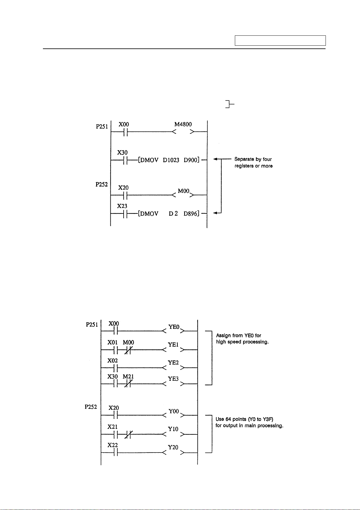
(2) Data area
Even with commands that handle data (numerical values) during the MOV command, etc., the bit
area must be separated by 64 points or more and the data register (D) and file register (R)
separated by four registers or more.
Example) Use D0 to D896 for main processing
Use D900 to D1023 for high speed processing
Separate by four registers or more
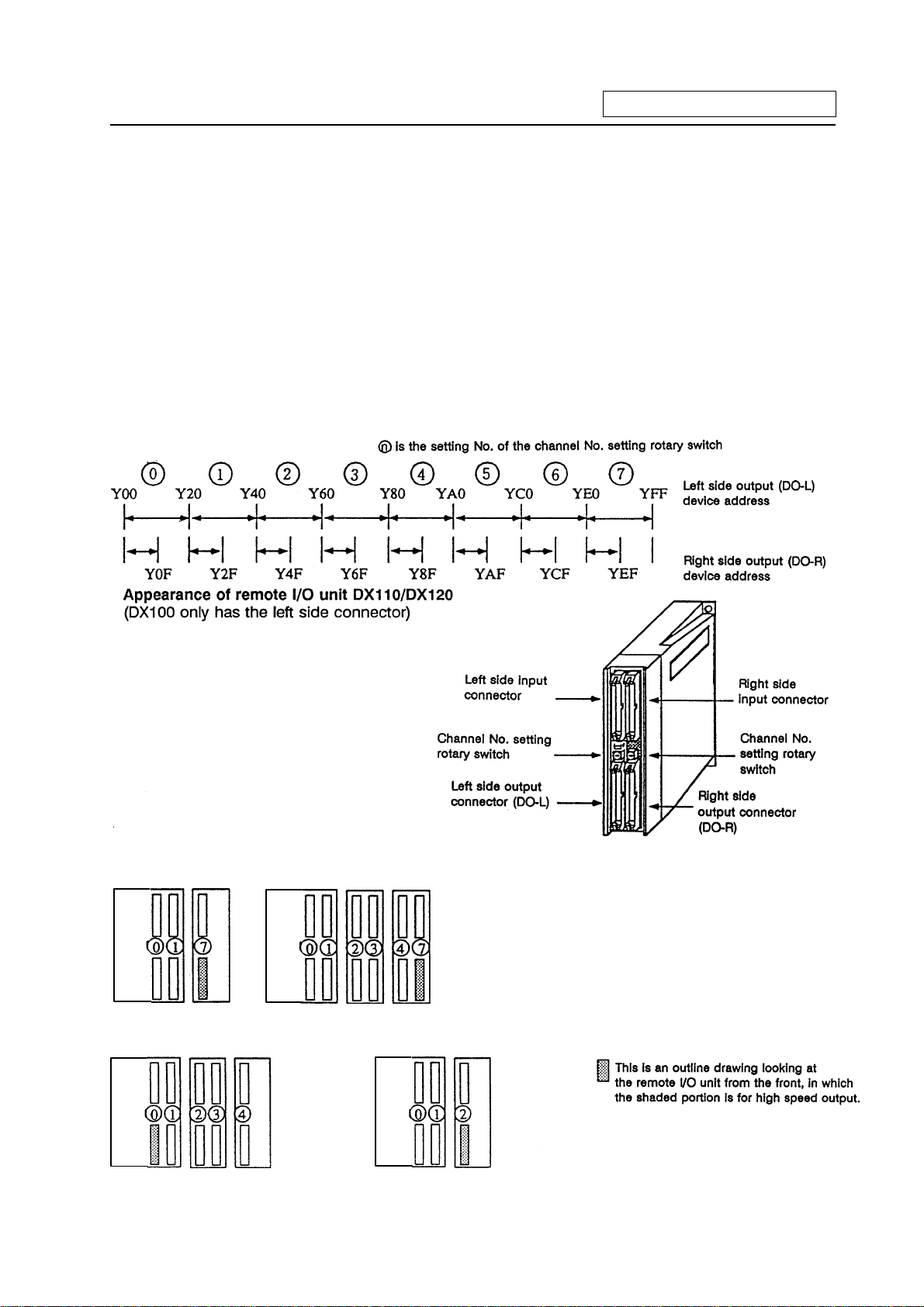
3.4.2 Separation of Remote I/O Output
When handling high speed output during the high speed process, the main processing output and
high speed processing output cannot be used together in the same remote I/O unit (32 points in
channel No. setting rotary switch). A separate 32 points for high speed processing output or a
16-point remote I/O unit will be required.
MOV commands, etc., that extend over differing remote I/O units must not be enforced during either
main processing or high speed processing. If these must be enforced, the channel No. setting rotary
switch for the output unit used in the main processing and the output unit used for the high speed
processing must be set 1 or more apart.
M10
- 8 -
Page 16
3. Input/Output Signals
(Usage example 1) Avoid interference with the main process by assigning 7 (last channel) for the
channel No. rotary switch for high speed processing output.
For example, use YE0 to YFF (for 32-point DO-L) or YE0 to YEF (for 16-point
DO-R) as the high speed processing output.
(Refer to <Usage examples 1-1, 1-2 and 1-3> below.)
(Usage example 2) Assign Y0 to Y1F (32-point) for high speed processing, and use Y20 and
following for the main process.
(Refer to <Usage example 2> below.)
(Usage example 3) Assign the device after the device used for main processing for the high speed
process.
For example, if the devices up to Y2D are used for the main process, use Y40 to
Y5F (channel No. setting rotary switch No.: 2) for the high speed process.
(Refer to <Usage example 3> below.)
Relation of channel No. setting switch and device No.
(Devices are YE0
and following)
DX35*/45* DX100 DX100
/120
<Usage example 1-2><Usage example 1-1>
Usage examples 1-2 show the
assignment for the 16-poi nt unit
as the No. of high speed output
points is relatively low.
DX35*/45* DX110/120DX35*/45* DX100
<Usage example 3><Usage example 2>
DX35*/45* DX100
- 9 -
Page 17
4. Parameters
4. Parameters
4.1 PLC Constants
The parameters that can be used in user PLC include PLC constants set in the data type.
Set up data is stored in a file register and is backed up. In contrast, if data is stored in the file register
corresponding to PLC constant by using sequence program MOV instruction, etc., it is backed up.
However, display remains unchanged. Display another screen once and then select the screen
again.
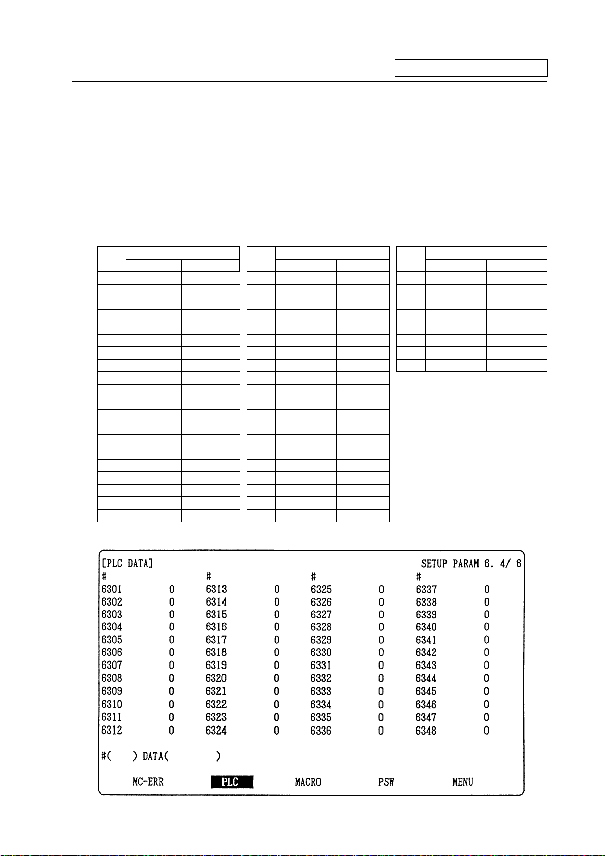
48 PLC constants are set (the setting range is ±8 digits). (Signed 4-byte binary data)
The correspondence between the PLC constants and file registers is listed below. The setting and
display screens are also shown.
Corresponding file registers
#
High order Low order
6301 R2801 R2800 6321 R2841 R2840 6341 R2881 R2880
6302 R2803 R2802 6322 R2843 R2842 6342 R2883 R2882
6303 R2805 R2804 6323 R2845 R2844 6343 R2885 R2884
6304 R2807 R2806 6324 R2847 R2846 6344 R2887 R2886
6305 R2809 R2808 6325 R2849 R2848 6345 R2889 R2888
6306 R2811 R2810 6326 R2851 R2850 6346 R2891 R2890
6307 R2813 R2812 6327 R2853 R2852 6347 R2893 R2892
6308 R2815 R1814 6328 R2855 R2854 6348 R2895 R2894
6309 R2817 R2816 6329 R2857 R2856
6310 R2819 R2818 6330 R2859 R2858
6311 R2821 R2820 6331 R2861 R2860
6312 R2823 R2822 6322 R2863 R2862
6313 R2825 R2824 6333 R2865 R2864
6314 R2827 R2826 6334 R2867 R2866
6315 R2829 R2828 6335 R2869 R2868
6316 R2831 R2830 6336 R2871 R2870
6317 R2833 R2832 6337 R2873 R2872
6318 R2835 R2834 6338 R2875 R2874
6319 R2837 R2836 6339 R2877 R2876
6320 R2839 R2838 6340 R2879 R2878
PLC constant screen
Corresponding file registers Corresponding file registers
#
High order Low order
#
High order Low order
- 10 -
Page 18
4. Parameters
4.2 Bit Selection Parameters
The parameters that can be used in user PLC include bit selection parameters set in the bit type.
Set up data is stored in a file register and is backed up.
For use in bit operation in a sequence program, the file register contents are transferred to temporary
memory (M) using the MOV command. In contrast, if data is stored in the file register corresponding
to bit selection by using the MOV command etc., it is backed up. However, display remains
unchanged. Once display another screen and again select screen.
The corresponding between the bit selection parameters and file registers is listed below. The setting
and display screens are also shown.
Corresponding
#
file register
6401 R2900-LOW 6433 R2916-LOW 6449 R2924-LOW 6481 R2940-LOW
6402 R2900-HIGH 6434 R2916-HIGH 6450 R2924-HIGH 6482 R2940-HIGH
6403 R2901-L 6435 R2917-L 6451 R2925-L 6483 R2941-L
6404 R2901-H 6436 R2917-H 6452 R2925-H 6484 R2941-H
6405 R2902-L 6437 R2918-L 6453 R2926-L 6485 R2942-L
6406 R2902-H 6438 R2918-H 6454 R2926-H 6486 R2942-H
6407 R2903-L 6439 R2919-L 6455 R2927-L 6487 R2943-L
6408 R2903-H 6440 R2919-H 6456 R2927-H 6488 R2943-H
6409 R2904-L 6441 R2920-L 6457 R2928-L 6489 R2944-L
6410 R2904-H 6442 R2920-H 6458 R2928-H 6490 R2944-H
6411 R2905-L 6443 R2921-L 6459 R2929-L 6491 R2945-L
6412 R2905-H 6444 R2921-H 6460 R2929-H 6492 R2945-H
6413 R2906-L 6445 R2922-L 6461 R2930-L 6493 R2946-L
6414 R2906-H 6446 R2922-H 6462 R2930-H 6494 R2946-H
6415 R2907-L 6447 R2923-L 6463 R2931-L 6495 R2947-L
6416 R2907-H 6448 R2923-H 6464 R2931-H 6496 R2947-H
6417 R2908-L 6465 R2932-L
6418 R2908-H 6466 R2932-H
6419 R2909-L 6467 R2933-L
6420 R2909-H 6468 R2933-H
6421 R2910-L 6469 R2934-L
6422 R2910-H 6470 R2934-H
6423 R2911-L
6424 R2911-H 6472 R2935-H
6425 R2912-L 6473 R2936-L
6426 R2912-H 6474 R2936-H
6427 R2913-L 6475 R2937-L
6428 R2913-H 6476 R2937-H
6429 R2914-L 6477 R2938-L
6430 R2914-H 6478 R2938-H
6431 R2915-L 6479 R2939-L
6432 R2915-H 6480 R2939-H
Corresponding
#
file register
Use bit selection
parameters
#6401~#6448 freely.
Corresponding
#
file register
6471 R2935-L
Corresponding
#
file register
Bit selection parameter
#6449~#6496 are PLC
operation selection
parameters used by the
machine manufacturer
and MITSUBISHI. The
contents are fixed.
- 11 -
Page 19
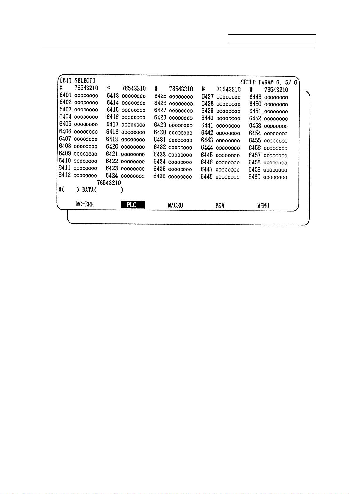
Bit selection screen
4. Parameters
- 12 -
Page 20
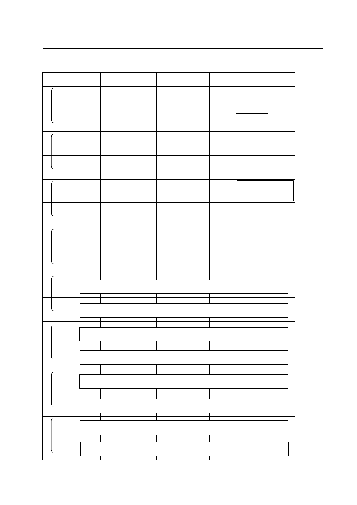
Contents of bit selection parameters #6449~#6496
4. Parameters
Symbol
name
#6449
R2924 L
0
#6450
R2924 H
1
#6451
R2925 L
2
#6452
R2925 H
3
#6453
R2926 L
4
#6454
R2926 H
5
#6455
R2927 L
6
7 6 5 4 3 2 1 0
NC card
Controller
thermal
alarm on
Setting
display unit
thermal
alarm on
External
alarm
message
display
- -
-
- - - - -
- - - - - - - -
-
Alarm/
operator
change
GX-Developer
communication on
GOT
communication
connection
Full screen
display of
message
PLC
development
environment
selection
Counter C
retention
Counter
(fixed)
retention
-
Integrating
timer T
retention
Operator
message
on
Onboard
editing not
possible
Integrating
timer
(fixed)
retention
PLC counter
program on
1 0
R
systemF system
Equivalent of
remote I/O 2ch
PLC timer
program on
Alarm
message on
- Onboard on
-
Message
language
change code
#6456
R2927 H
7
#6457
R2928 L
8
#6458
R2928 H
9
#6459
R2929 L
A
#6460
R2929 H
B
#6461
R2930 L
C
#6462
R2930 H
D
#6463
R2931 L
E
- - - - - - - -
High-speed input specification 1
High-speed input specification 2
High-speed input specification 3 (Spare)
High-speed input specification 4 (Spare)
High-speed output specification 1
High-speed output specification 2
High-speed output specification 3 (Spare)
#6464
R2931 H
F
High-speed output specification 4 (Spare)
- 13 -
Page 21

Symbol
name
#6465
0
R2932 L
#6466
1
R2932 H
#6467
2
R2933 L
#6468
3
R2933 H
#6469
4
R2934 L
#6470
5
R2934 H
#6471
6
R2935 L
#6472
7
R2935 H
#6473
8
R2936 L
#6474
9
R2936 H
#6475
A
R2937 L
#6476
B
R2937 H
#6477
C
R2938 L
#6478
D
R2938 H
#6479
E
R2939 L
#6480
F
R2939 H
4. Parameters
7 6 5 4 3 2 1 0
- -
- -
- -
-
- -
- -
-
-
-
-
Standard PLC
parameter
-
-
-
-
-
-
-
-
-
-
-
-
-
-
-
-
-
-
-
-
-
-
-
-
-
MC alarm 4
output off
-
-
-
(Note 1) Be sure to set the bits indicated - and blanks to 0.
(Note 2) Parameters #6481 to #6496 are reserved for debugging by Mitsubishi.
- 14 -
Page 22
5. Explanation of Devices
5. Explanation of Devices
5.1 Devices and Device Numbers
The devices are address symbols to identify signals handled in PLC. The device numbers are serial
numbers assigned to the devices. The device numbers of devices X, Y and H are represented in
hexadecimal notation. The device numbers of other devices are represented in decimal notation.
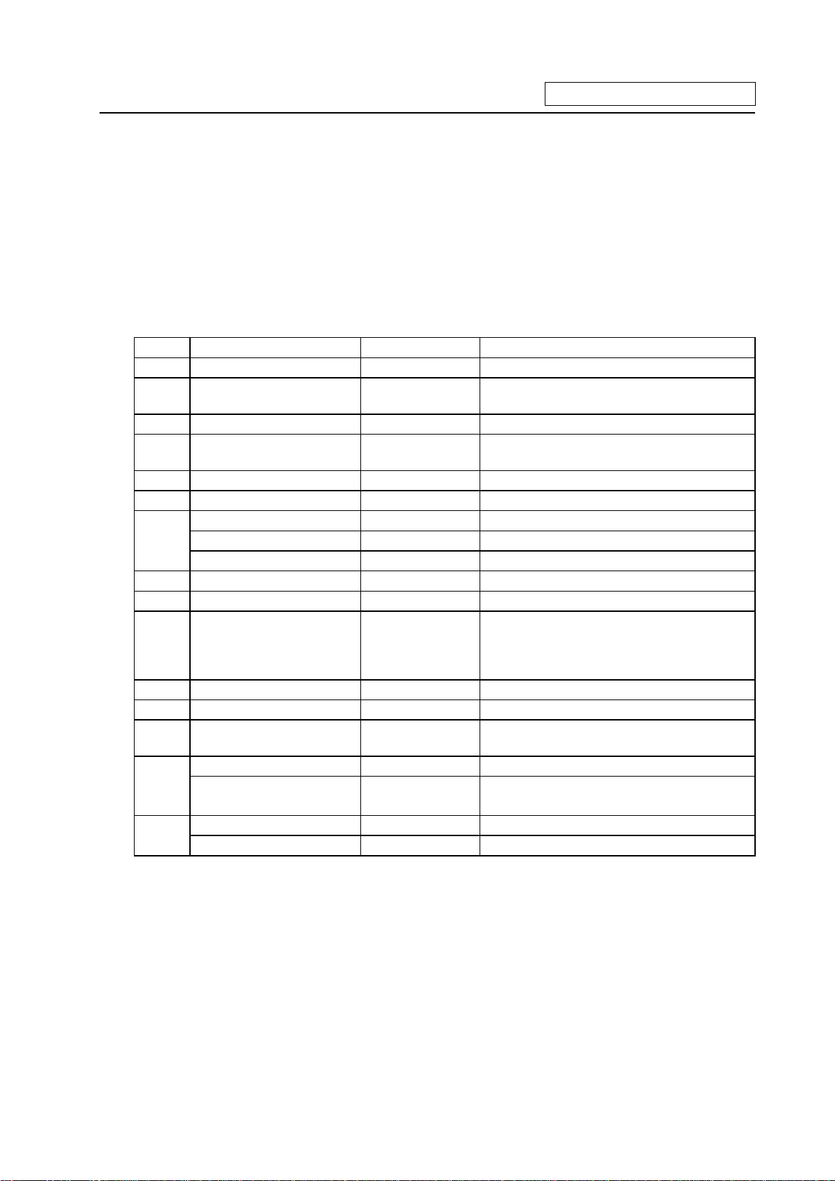
5.2 Device List
Device Device No. Unit Details
X* X0~XABF (2752 points) 1 bit Input signal to PLC. Machine input, etc.
Y* Y0~YDEF (3584 points) 1 bit Output signal from PLC.
Machine output, etc.
M M0~M8191 (8192 points) 1 bit Temporary memory
F F0~F127 (128 points) 1 bit Temporary memory, alarm message
interface
L L0~L255 (256 points) 1 bit Latch relay (backup memory)
SM* SM0~SM127 (128 points) 1 bit Special relay
T T0~T15 (16 points) 1 bit or 16 bits 10ms unit timer
T16~T95 (80 points) 1 bit or 16 bits 100ms unit timer
T96~T103 (8 points) 1 bit or 16 bits 100ms unit integrating timer
C C0~C23 (24 points) 1 bit or 16 bits Counter
D D0~D1023 (1024 points) 16 bits or 32 bits Data register for arithmetic operation
R* R0~R8191 (8192 points) 16 bits or 32 bits File register. R500 to R549 and R1900 to
R2799 are released to the user for interface
between the PLC and controller. R1900 to
R2799 are backed up by the battery.
Z Z0~Z1 (2 points) 16 bits Index of D or R address (±n)
N N0~N7 (8 points) — Master control nesting level
P* P0~P255 (256 points) — Label for conditional jump and subroutine
call
K K-32768~K32767 — Decimal constant for 16-bit command
K-2147483648~
K2147483647
H H0~HFFFF — Hexadecimal constant for 16-bit command
H0~HFFFFFFFF — Hexadecimal constant for 32-bit command
(Note 1) The applications of the devices having a * in the device column are separately determined.
Do not use the undefined device Nos., even if they are open.
(Note 2) When using temporary memory such as M device, separate READ and WRITE every 8bits.
— Decimal constant for 32-bit command
- 15 -
Page 23
5. Explanation of Devices
5.3 Detailed Explanation of Devices
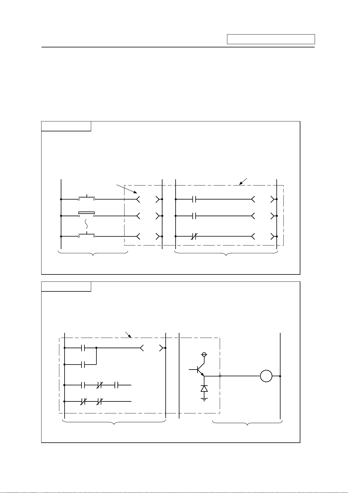
5.3.1 Input/output X, Y
Input/output X and Y are a window for executing communication with the PLC and external device or
CNC.
Input X
(a) This issued commands or data from an external device such as a push-button, changeover
switch, limit switch or digital switch to the PLC.
(b) Assuming that there is a hypothetical relay Xn built-in the PLC per input point, the program
uses the "A" contact and "B" contact of that Xn.
(c) There is no limit to the No. of "A" contacts and "B" contacts of the input Xn that can be used in
the program.
Hypothetical relay
PLC
PB1
LS2
PB16
X10
X11
X1F
Input circuit
X10
X11
X1F
Program
(d) The input No. is expressed with a hexadecimal.
Output Y
(a) This outputs the results of the program control to the solenoid, magnetic switch, signal lamp or
digital indicator, etc.
(b) The output can be retrieved with the equivalent of one "A" contact.
(c) There is no limit to the No. of "A" contacts and "B" contacts of the output Yn that can be used in
the program.
PLC
Y10
24V
Y10
Load
Y10
Y10
Program
(d) The output No. is expressed with a hexadecimal.
- 16 -
Output circuit
Page 24

5. Explanation of Devices
5.3.2 Internal Relays M and F, Latch Relay L
The internal relay and latch relay are auxiliary relays in the PLC that cannot directly output to an
external source.
Internal relays M
(a) These relays are cleared when the power is turned OFF.
(b) There is no limit to the No. of "A" contacts and "B" contacts of the internal relays that can be
used in the program.
(c) The internal relay No. is expressed with a decimal.
Internal relay F
Internal relay F is an interface for the alarm message display.
Use the bit selection parameter to determine whether to use this relay for the alarm message
interface. The target will be F0 to F127. This internal relay can be used in the same manner as the
internal relay M when not used as the alarm message interface.
Latch relay L
(a) The original state is held even when the power is turned OFF.
(b) There is no limit to the No. of "A" contacts and "B" contacts of the latch relay that can be used
in the program.
(c) The latch No. is expressed with a decimal.
5.3.3 Special Relays SM
The special relays are relays having fixed applications such as the carrier flag for operation results
and the display request signal to the setting and display unit. Even the relays of SM0 to SM127 that
are not currently used must not be used as temporary memory.
Special relays SM
(a) This relay is cleared when the power is turned OFF.
(b) There is no limit to the No. of "A" contacts and "B" contacts of the special relays that can be
used in the program.
(c) The special relay No. is expressed with a decimal.
- 17 -
Page 25
5. Explanation of Devices
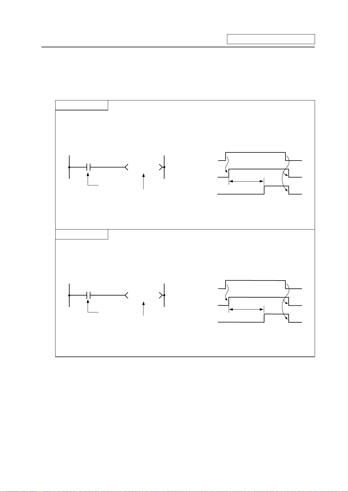
5.3.4 Timer T
(1) The 100ms timer, 10ms timer and 100ms integrated timer are available for this count-up type
timer.
100ms Timer T
(a) When the input conditions are set, the count starts. When the set value is counted, that timer
contact will turn ON.
(b) If the input conditions are turned OFF, the 100ms timer count value will be set to 0, and the
contact will turn OFF.
ON
X5
Input conditions
T57 K 5 0
100ms timer
T57 coll OFF
T57 c ontact OFF
X5 OFF
ON
5 seconds
ON
(c) When #6449 bit0=1, the value is set with a decimal (Kn), and can be designated from 1 to
32767 (0.1 to 3276.7 s). The data register (D) data can also be used as the setting value. File
register (R) cannot be used.
10ms Timer T
(a) When the input conditions are set, the count starts. When the set value is counted, that timer
contact will turn ON.
(b) If the input conditions are turned OFF, the 10ms timer count value will be set to 0, and the
contact will turn OFF.
ON
X5
T1 K500
Input conditions
10ms timer
X5 OFF
T1 coll OFF
T1 contact OFF
ON
5 seconds
ON
(c) When #6449 bit0=1, the value is set with a decimal (Kn), and can be designated from 1 to
32767 (0.01 to 327.67 s). The data register (D) data can also be used as the setting value. File
register (R) cannot be used.
- 18 -
Page 26

5. Explanation of Devices
100ms integrated timer T
(a) When the input conditions are set, the count starts. When the set value is counted, that timer contact
will turn ON.
(b) Even the input conditions are turned OFF, the 100ms integrated timer current value (count value)
will be held, and the contact state will not change.
(c) The 100ms integrated timer count value will be set to 0 and the contact will turn OFF when the RST
command is executed.
X5
Input conditions
X7
100ms cumulative timer
T233 K100
RST T233
X5 OF F
X7 OF F
ON
9 seconds
1.5 seconds
6 seconds
ON
Reset input
T233 reset command
T233 coll OFF
T233 contact OFF
T233 current value
ON
9 seconds
1 seconds
ON
0 1 90 91 100 0 1 60
~
~
6 seconds
~
(d) When #6449 bit0=1, the value is set with a decimal (Kn), and can be designated from 1 to 32767
(0.1 to 3267.7 s). The data register (D) data can also be used as the setting value. File register (R)
cannot be used.
(e) When the bit selection parameter (#6449 bit2=1) is set, the 100ms integrated timer current value
(count value) will be held even when the power is turned OFF.
(2) With the device T, the contact • coil is handled as bit device, and the current value is handled as
word device. In the function commands described after, the word device T indicates the current
value even if there is no description about it.
(3) When #6449 bit0=0 is set, timer value can be specified with the parameter set in the setting and
display unit. At this time, the relationship between timer device and parameter is as shown below.
Device Parameter
T0 to T15
T56 to T135
T232 to T239
#6000 to #6015
#6016 to #6095
#6096 to #6103
(Note 1) T16 to T55, T136 to T231, and T240 to T255 are specified with a program (Kn) regardless of
#6449 bit0.
(Note2) Even when #6449 bit0=0, Kn is required for a sequence program. Note that, however, the Kn
value is invalid.
(Note 3) When the data register (D) is used as setting value, the data register (D) details will be the
setting value regardless of #6449 bit0.
- 19 -
Page 27
5. Explanation of Devices
5.3.5 Counter C
(1) The counter counts up and detects the rising edge of the input conditions. Thus, the count will not
take place when the input conditions are ON.
Counter C
(a) The value is set with a decimal, and can be designated from 1 to 32767. The data register (D)
data can also be used as the setting value. File register (R) cannot be used.
(b) The counter count value will not be cleared even if the input conditions turn OFF. The counter
count value must be cleared with the RST command.
(c) When the bit selection parameter is set, the counter current value (count value) will be held
even when the power is turned OFF. Note that some can not be held depending on the version
of CNC.
(2) With the device C, the contact • coil is handled as bit device, and the current value (counter
value) is handled as word device. In the function commands described after, the word device C
indicates the current value (counter value) even if there is no description about it.
(3) The counter setting value can be set with the setting and display unit using device C. (Variable
counter)
Whether the setting value (Kn) programmed with the sequence program or the setting value set
from the setting and display unit is valid is selected with the bit selection parameters. The
changeover is made in a group for C0 to C23. Even when set from the setting and display unit,
the setting value (Kn) program will be required in the sequence program. However, the Kn value
will be ignored. When the data register (D) is used for the setting value, the data register (D)
details will be used as the setting value regardless of the parameter.
(Note) The setting value for device C24 to C127 of counter C cannot be set from the setting and
display unit.
5.3.6 Data Register D
(1) The data register is the memory that stores the data in the PLC.
(2) The data register has a 1-point 16-bit configuration, and can be read and written in 16-bit units.
To handle 32-bit data, two points must be used. The data register No. designated with the 32-bit
command will be the low-order 16-bit, and the designated data register No. +1 will be the
high-order 16-bit.
Circuit example
0
Data storage
D1
Higth-order 16 -bit
(X1F X10)
~
DMOV K8X0
D0
Low-order 16-bit
(XF X0)
~
D0
The X0 to 1F data is
stored in D0,1.
(3) The data that is stored once in the sequence program is held until other data is stored.
(4) The data stored in the data register is cleared when the power is turned OFF.
(5) Values that can be stored: Decimal -32768 to 32767 For 16-bit command
Hexadecimal 0 to FFFF
Decimal -2147483648 to 2147483647 For 32-bit command
Hexadecimal 0 to FFFFFFFF
(Using Dn)
(Using Dn+1, Dn)
(6) Data registers D0 to D1023 are all user release data registers.
- 20 -
Page 28
5. Explanation of Devices
5.3.7 File Register R
(1) As with the data registers, the file registers are memories used to store data. However, there are
some that have fixed applications, and those that are released.
(2) The file register has a 1-point 16-bit configuration, and can be read and written in 16-bit units.
To handle 32-bit data, two points must be used. The file register No. designated with the 32-bit
command will be the low-order 16-bit, and the designated file register No. +1 will be the
high-order 16-bit.
(Example) Use of the DMOV command is shown below.
Circuit example
0
Data storage
R1
Higth-order 16 -bit
(X1F~X10)
DMOV K8X0
R0
Low-order 16-bit
(XF~X0)
R0
The X0 to 1F data is
stored in R0,1.
(3) The data that is stored once in the sequence program is held until other data is stored.
(4) With the file registers, the following registers are the user release.
R500 to R549, R1900 to R2799
The following registers of the registers above are not cleared when the power is turned OFF.
R1900 to R2799
The other file registers have fixed applications such as interface of the PLC and CNC, parameter
interface, etc.
(5) Values that can be stored: Decimal -32768 to 32767 For 16-bit command
Hexadecimal 0 to FFFF
Decimal -2147483648 to 2147483647 For 32-bit command
Hexadecimal 0 to FFFFFFFF
(Using Dn)
(Using Dn+1, Dn)
- 21 -
Page 29
5. Explanation of Devices
5.3.8 Index Registers Z
(1) The index registers are used as ornaments for the device (T, C, D, R).
159
165
MOV
MOV
K3 Z0
K4X0
D5Z0
D5Z0 Indicates D (5+Z) = D8
(2) The index register has a 1-point 16-bit configuration, and can be read and written in 16-bit units.
(3) The data stored in the index register is cleared when the power is turned OFF.
(4) Values that can be stored: Decimal -32768 to 32767
Hexadecimal 0 to FFFF
(Note) The CRT display of the index registers Z is as shown below.
MOV
MOV X0 D5
K3
K4
Z0
Z0
- 22 -
Page 30
5. Explanation of Devices
5.3.9 Nesting N
(1) This indicates the master control nesting structure.
(2) The master control nesting (N) is used in order from smallest number.
N0
A
M15
MC N0 M15
Execute when A conditions are set.
Execute when A,B conditions are set.
Execute when A,B,C conditions are set.
Reset MC2 to 7
Execute when A,B conditions are set.
Reset MC1 to 7
Execute when A conditions are set.
Reset MC0 to 7
Execute regardless of A,B,C conditions.
N1
N2
M16
M17
B
C
MC N1 M16
MC N2 M17
MCR N2
MCR
N1
MCR
N0
(a) The conditions for each master control to turn ON are as follow.
MC N0 M15 .......... ON when condition A is ON
MC N1 M16 .......... ON when conditions A, B are ON
MC N2 M17 .......... ON when conditions A, B, C are ON
(b) The timer and counter when the master control is OFF is as follows.
· 100ms timer, 10ms timer : The count value is set to 0.
· 100ms integrated timer : The current count value is retained.
· Counter : The current counter value is retained.
· OUT command : All turn OFF.
- 23 -
Page 31

5. Explanation of Devices
5.3.10 Pointer P
(1) The pointer indicates the branch command (CJ, CALL) jump destination. The pointer No.
assigned at the jump destination head is called the label.
(2) Pointers P0 to P159, P251, P252, P255 are user release pointers.
(3) P255 always indicates END.
(P255 can be used as a device for CJ command, etc, but cannot be used as a label. This cannot
be used for the CALL command device.)
Pointer
Label
P20
501
33
36
X13
CJ P20
Jump to label
P20 (step 501)
when X13 turns ON.
723
726
X17
P255CJ
Jump to END when
X17 t urns O N.
(4) The special usages of the pointers other than P255 are shown below.
P251: Label for starting PLC high-speed processing program.
P252: Label for starting PLC main (ladder) processing program.
CAUTION
The PLC will not operate correctly if Notes 1 to 4 are not observed.
(Note 1) Do not omit P252 label even when there is only a PLC main processing program.
(Note 2) P251 and P252 cannot be used as CJ or CALL command devices.
(Note 3) Do not create a program in which the P** in the PLC high-speed processing program is
jumped to from the PLC main processing program.
(Note 4) The P** used as a CJ or CALL command device must also be programmed as a label.
- 24 -
Page 32

5. Explanation of Devices
5.3.11 Decimal Constant K
(1) The decimal constant can be used in the following ways.
(a) Timer counter setting value: Designate in the range of 1 to 32767.
(b) Pointer No.: 0 to 159
(c) Bit device digit designation: 1 to 8
(d) Basic command, function command, exclusive command value setting
· 16-bit command: -32768 to 32767
· 32-bit command: -2147483648 to 2147483647
(2) The decimal constant is stored in the binary value (binary) in the PLC.
5.3.12 Hexadecimal Constant H
(1) The hexadecimal constant is used to designate the basic command, function command and
exclusive command values.
· 16-bit command: 0 to FFFF
· 32-bit command: 0 to FFFFFFFF
- 25 -
Page 33

6. Explanation of Commands
6.1 Command List
6.1.1 Basic Commands
6. Explanation of Commands
Class
Basic
command Bit
Process
unit
Command
sign
LD
LDI
AND
ANI
OR
ORI
ANB
ORB
OUT
Symbol
Process details
Start of logic operation
(A contact operation start)
Start of logic denial operation
(B contact operation start)
Logical AND
(A contact serial connection)
Logical AND denial
(B contact serial connection)
Logical OR
(A contact parallel connection)
Logical OR denial
(B contact parallel connection)
AND between logical blocks (Serial
connection between blocks)
OR between logical blocks
(Parallel connection between blocks)
Device output
1~3 52
No.
of
Page
steps
1 42
1 42
1 44
1 44
1 46
1 46
1 48
50
1
(Note) The "ANDP" command is alternatively used for the MELSEC PLC development tool (GX
Developer).
SET
RST
MC
MCR
PLS
PLF
SFT
MPS
MRD
MPP
DEFR
(ANDP)
MPS
MRD
MPP
SET
RST
M
MCR
PLS D
PLF
SFT
D
D
nD
n
D
D
1 58
1~2 60
2 62
1 62
2 64
2 64
4 66
1 68
1 68
1 70
Device set
Device reset
Master control start
Master control release
Generate one cycle worth of pulses at rising
edge of input signal
Generate one cycle worth of pulses at falling
edge of input signal
Device 1-bit shift
Registration of logical operation result
Read of operation results registered in MPS 1 68
Reading and resetting of operation results
registered in MPS
Generate one cycle worth of pulses to
oper-ation results at rising edge of input
signal (Note)
- 26 -
Page 34

6.1.2 Function Commands
(1) Comparison commands
Class
Process
unit
Command
sign
LD=
Symbol
=
S1 S2
6. Explanation of Commands
Process details
No.
of
Page
steps
3 74
16-bit
=
>
32-bit
16-bit
32-bit
AND=
OR=
LDD=
ANDD=
ORD=
LD>
AND>
OR>
LDD>
ANDD>
ORD>
=
=
D=
D=
D=
>
>
>
D>
D>
D>
S1 S2
S1 S2
S1 S2
S1 S2
S1 S2
S1 S2
S1 S2
S1 S2
S1 S2
S1 S2
S1 S2
Continuity state when (S1) = (S2)
Non-continuity state when (S1) =/ (S2)
Continuity state when
(S1+1, S1)=(S2+1, S2)
Non-continuity state when
(S1+1, S1) = (S2+1, S2)
Continuity state when (S1) > (S2)
Non-continuity state when (S1) <= (S2)
Continuity state when
(S1+1, S1) > (S2+1, S2)
Non-continuity state when
(S1+1, S1) <= (S2+1, S2)
3 74
3 74
3~4 76
3~4 76
3~4 76
3 78
3 78
3 78
3~4 80
3~4 80
3~4 80
16-bit
<
32-bit
LD<
AND<
OR<
LDD<
ANDD<
ORD<
<
<
<
D<
D<
D<
S1 S2
S1 S2
S1 S2
S1 S2
S1 S2
S1 S2
- 27 -
Continuity state when (S1) < (S2)
Non-continuity state when (S1) >= (S2)
Continuity state when
(S1+1, S1) < (S2+1, S2)
Non-continuity state when
(S1+1, S1) >= (S2+1, S2)
3 82
3 82
3 82
3~4 84
3~4 84
3~4 84
Page 35

+
(2) Arithmetic operation commands
Class
Process
unit
Command
sign
Symbol
6. Explanation of Commands
Process details
No.
of
steps
Page
+
–
*
/
+1
–1
16-bit
32-bit
16-bit
32-bit
16-bit
32-bit
16-bit
32-bit
16-bit
32-bit
16-bit
32-bit
+
D+
-
D-
*
D*
/
D/
INC
DINC
DEC
DDEC
D+
-
D-
*
D*
/
D/
S1 S2 D
S1 S2 D
S1 S2 D
S1 S2 D
S1 S2 D
S1 S2 D
S1 S2 D
S1 S2 D
INC
D
DINC
DDEC
DEC
D
D
D
(S1) + (S2) (D)
(S1+1, S1) + (S2+1, S2) (D+1, D)
(S1) – (S2) (D)
(S1+1, S1) – (S2+1, S2) (D+1, D)
(S1) x (S2) (D+1, D)
(S1+1, S1) x (S2+1, S2)
(D+3, D+2, D+1, D)
.
(S1)
(S2) (D)
=
.
Quotient (D) Remainder (D+1)
(S1+1, S1)
Quotient (D+1,D) Remainder (D+3, D+2)
(D) + 1 (D)
(D+1, D) + 1 (D + 1, D)
(D) – 1 (D)
(D + 1, D) – 1 (D + 1, D)
.
(S2+1, S2)
=
.
4 86
4~5 88
4 90
4~5 92
4 94
5~6 96
5 98
5~6 100
2 102
2 104
2 106
2 108
(3) BCD BIN conversion commands
Class
BCD
BIN
Process
unit
16-bit
32-bit
16-bit
32-bit
Command
sign
BCD
DBCD
BIN
DBIN
Symbol
BCD
DBCD
BIN
DBIN
SD
SD
SD
SD
No.
of
Page
step
3 110
4 112
3 114
4 116
Process details
BCD conversion
(S) (D)
BIN (0 to 9999)
BCD conversion
(S1+1,S1) (D+1,D)
BIN (0 to 99999999)
BIN conversion
(S) (D)
BIN (0 to 9999)
BIN conversion
(S1+1,S1) (D+1,D)
BIN (0 to 99999999)
- 28 -
Page 36

⋅
⋅
(4) Data transmission commands
Class
Process
unit
Command
sign
Symbol
6. Explanation of Commands
Process details
No.
of
step
Page
MOV
DMOV
XCH
DXCH
BMOV
FMOV
BMOV S D n
FMOV S D n
Trans-
mission
Conversion
Batch
transmission
Batch transmission of
same data
16-bit
32-bit
16-bit
32-bit
16-bit
16-bit
(5) Program branch commands
Class
Jump —
Program
end
Subroutine
call
Return
Process
unit
—
—
—
Command
sign
CJ
FEND
CALL
RET
SD
MOV
D1 D2
XCH
Symbol
CJ
FEND
CALL P**
RET
SD
DMOV
DXCH D1
P**
D2
(S)
(S+1,S)
(D1)
⋅
(D1+1,D1)
⋅
(S)
(S)
Process details
Jump to P** after input conditions are met
End process during sequence program 1 132
Execute P** sub-routine program after
input conditions are met
Return to main program from subroutine
program
(D)
(D2)
(D+1,D)
(D2+1,D2)
(D)
(D)
3 118
3~4 120
4 122
4 124
5 126
5 128
No.
of
step
2 130
2
1 134
Page
134
n
n
- 29 -
Page 37

(6) Logical operation commands
Class
Process
unit
Comman
d sign
Symbol
6. Explanation of Commands
Process details
No.
of
step
Page
Logical AND
Logical OR
Exclusive OR
Complement
of 2
16-bit
32-bit
16-bit
32-bit
16-bit
32-bit
16-bit
WAND
DAND
WOR
DOR
WXOR
DXOR
NEG
WAND S1 S2 D
DAND
S D
WOR S1 S2 D
SD
DOR
WXOR S1 S2 D
DXOR SD
NEG
D
(S1) ^ (S2) (D)
(D + 1, D) ^ (S + 1, S) (D + 1, D)
(S1) V (S2) (D)
(D + 1, D) V (S + 1, S) (D + 1, D)
(S1) V– (S2) (D)
(D + 1, D) (S + 1, S) (D + 1, D)
(D) + 1 (D)
4 136
3~4 138
4 140
3~4 142
4 144
3~4 146
2 148
- 30 -
Page 38

(D)
(
)
(D)
(
)
(D)
0
0
0
0
(7) Rotation commands
Class
Right
rotation
Left rotation
Right shift
Process
unit
16-bit
32-bit
16-bit
32-bit
16-bit
Device
unit
Command
sign
ROR
RCR
DROR
DRCR
ROL
RCL
DROL
DRCL
SFR
DSFR
6. Explanation of Commands
Symbol Process details
Dn
ROR
RCR Dn
DROR
D n
DRCR
D n
Dn
ROL
Dn
RCL
DROL D n
DRCL
SFR
DSFR
n
D
n
D
n
D
b15
Rotate n bits right.
b15
Rotate n bits right.
(D+1) (D)
Rotate n bits right.
D+1
Rotate n bits right.
SM12 (D) b0 b15
Rotate n bits left.
SM12 (D) b0 b15
Rotate n bits left.
Rotate n bits left.
Rotate n bits left.
b15
0 0
b0
b0
b0b31 SM12 b16 b15
b0b31 SM12 b16 b15
(D+1) (D)
D+1
bn
b0
b0 SM12b15
n
(D)
SM12
SM12 (D)
b0 b31SM12 b16 b15
b0 b31SM12 b16 b15
No.
of
Page
step
3 150
3 152
3 154
3 156
3 158
3 160
3 162
3 164
3 166
4 168
Left shift
16-bit
Device
unit
SFL
DSFL
SFL
DSFL D
b15 bn b
n
D
b15
SM12
n
n
(D)
3 170
b
0~0
4 172
- 31 -
Page 39

(D)
(S)
(D)
6. Explanation of Commands
(8) Data processing commands
Class
Search
Number of
bits set to 1
Decode
Average
value
Process
unit
16-bit
16-bit
n
-bit
2
16-bit
16-bit
Command
sign
SER
SUM
DECO
SEG
S.AVE
Symbol Process details
(S1)
SER S1 S2 D
SD
SUM
DECO S D n
SD
SEG
S.AVE S D n
b15
8
256 decode
(S)
16-bit data average value
n
1
Σ (S+i) (D)
n
i=1
(D) :Match No.
(D+1) :Number of match
(S)
Decode
n
b3 b0
(S2)
n
data pieces
b0
Number of bits
set to 1.
7SEG
2
n
bits
(9) Other function commands
Class
Carry flag
set
Carry flag
reset
BIT 1-bit
Process
unit
—
—
Command
sign
S.STC
S.CLC
LDBIT
(<=)
ANDBIT
(<=)
ORBIT
(<=)
LDBII
(< >)
ANDBII
(< >)
ORBII
(< >)
Symbol
BIT
BIT
BIT
BII
BII
BII
S.STC
S.CLC
S1 n
S1 n
S1 n
S1 n
S1 n
S1 n
Process details
Carry flag contact (SM12) is turned on. 1 184
Carry flag contact (SM12) is turned off. 1 184
Bit test (A contact operation start handling)
(Note)
Bit test (A contact series connection
handling)
Bit test (A contact parallel connection
handling)
Bit test (B contact operation start handling)
(Note)
Bit test (B contact series connection
handling)
Bit test (B contact parallel connection
handling)
(Note)
(Note)
(Note)
(Note)
(Note) The comparison operation commands are alternatively used for the MELSEC PLC development tool
(GX Developer).
No.
of
step
6
4
5
3
5 182
No.
of
step
2 186
2 186
2 186
2 188
2 188
2 188
Page
174
176
178
180
Page
- 32 -
Page 40

6.1.3 Exclusive commands
Class
ATC —
ROT —
TSRH
DDB
Process
—
—
unit
Command
S.TSRH
S.DDBA
(Asynchro-
S.DDBS
(Synchro-
sign
S.ATC
S.ROT
nous)
nous)
Symbol
S.ATC Kn Rn Rm Mn
S.ROT
S.TSRH
KnRnRm
Rn
S.DDBA Rn/Dn
S.DDBS
Rm
Mn
Mn
Rn
6. Explanation of Commands
Process details
K1: Tool number search 198
K2: Tool number AND search 199
K3: Tool change 200
K4: Random position tool change 201
K5: Forward rotation of pointer 202
K6: Reverse rotation of pointer 202
K7: Normal rotation of tool table 203
K8: Reverse rotation of tool table 203
K9: Tool data read 204
K10: Tool data write 205
K11: Automatic write of tool data
K1: Rotary body index 211
K3: Ring counter
Spare tool selection in tool life management
Data designated after Rn/Dn is read/written.
Data designated after Rn is read/written.
No.
of
Page
step
5
206
5
215
4 216
2 227
2 230
- 33 -
Page 41

6. Explanation of Commands
6.2 Command Formats
6.2.1 How to Read the Command Table
The basic command and function command explanations are shown below.
Example of D+ command
······BIN 32-bit addition
D+
Bit device
X Y M L SM F T C D R Z K H P N
S1
S2
D
The devices that can be used
with the D+ command are circled.
The command signal is indicated.
Usable device
Word device
Constant
A circle is indicated if digit
designation of the bit device is
possible.
Pointer Level
Digit
No. of
Index
steps
designation
4/5
The No. of steps of the D+ command is indicated.
This is a No. of steps required for the store in the controller.
In programming with MELSEC PLC development tool (GX Developer),
the displayed No. of steps may be different from this No. of steps.
Description such as "4/5" indicates that the No. of steps is different
depending on the designation device. For the 32-bit command, two
steps are required for the constant. In the example for the D+ command,
if S2 is the word device, the No. of steps will be 4 steps, and if S2 is the
constant, the No. of steps will be 5 steps.
The commands that can use an
index (Z) are circled.
Such a command is only the
MOV command in this manual.
setting data
Addition data or head No.
of device where addition
Addition command
D+
D+
The D+ command circuit display format is indicated.
S1
S2
D
The functions first, then execution conditions, then program examples are described on the following
pages.
- 34 -
S1
data is stored.
Addition data or head No.
of device where addition
S2
data is stored.
Head No. of device to
D
store addition results.
Page 42

6. Explanation of Commands
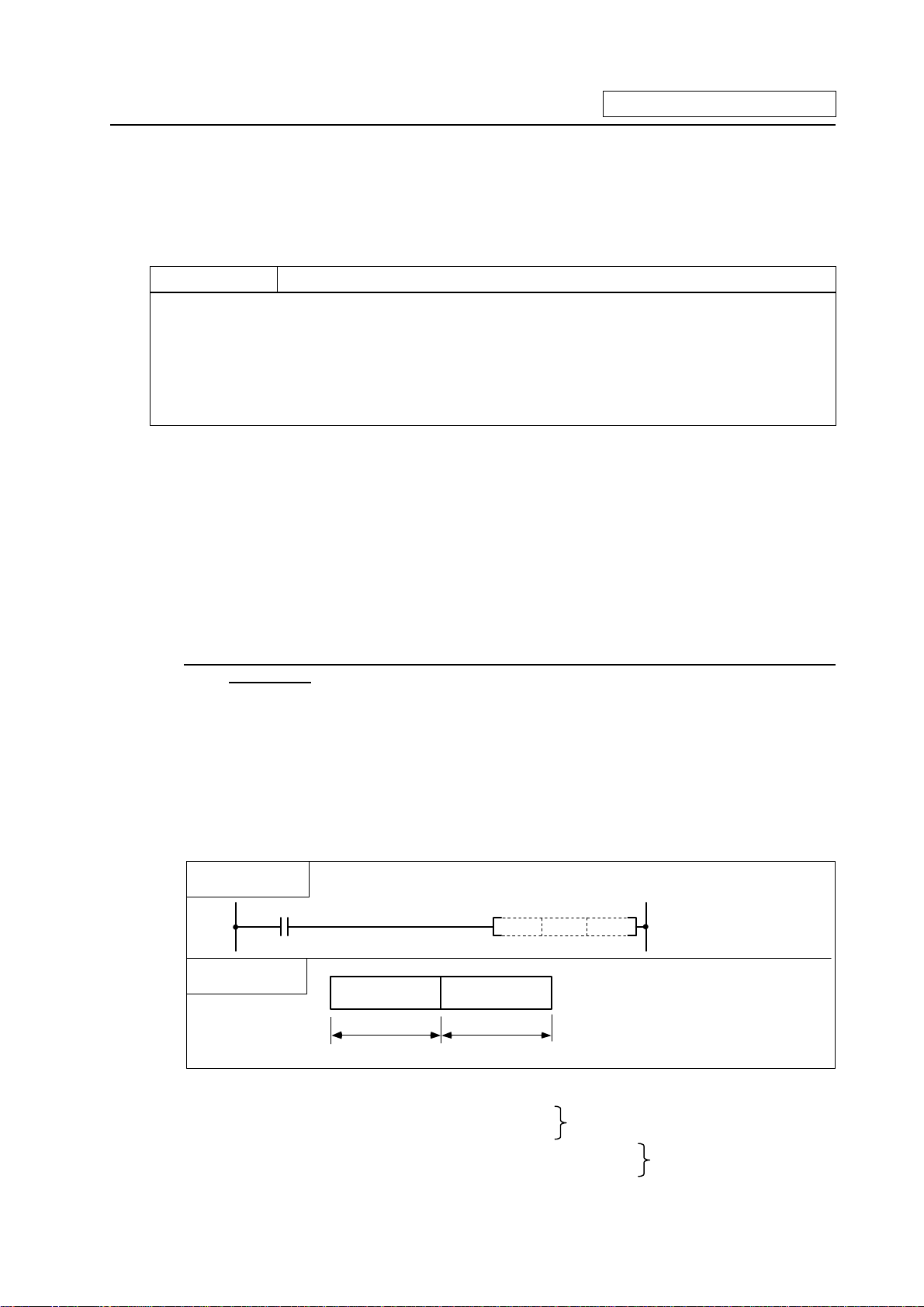
6.2.2 No. of Steps
The basic No. of steps in the sequence command includes step 1 to step 6.
Main examples of each step are shown below.
Basic No.
of steps
Step 1
Step 2
Step 3 MOV, =, BCD, OUT T
Step 4 DMOV, +, -, XCH
Step 5 D+, D-
Step 6
As shown above, the command code, source and destination in basic No. of steps for the command
are equivalent to one step each. Only some of the command codes and the 32-bit command constant
K or H use two steps.
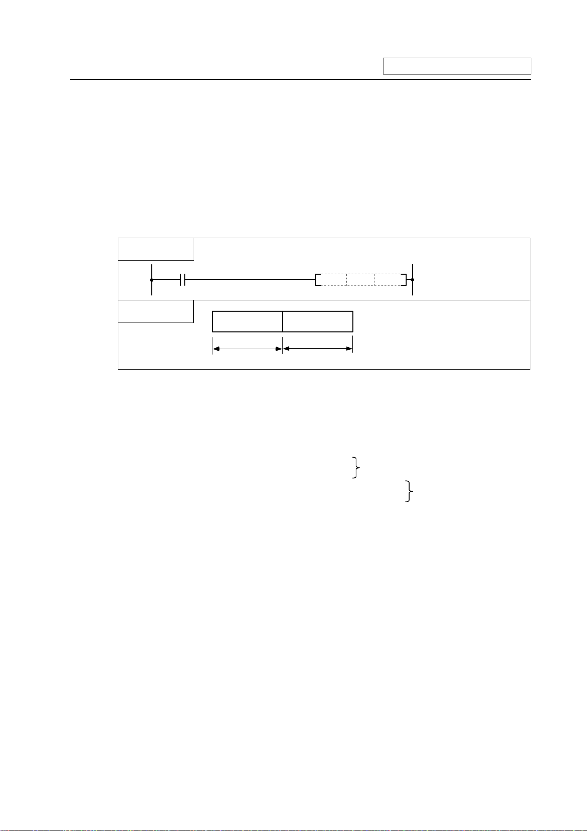
(Note) If the constant value in the DMOV or D* command, etc., is small, a display in which there is a
Command (mnemonic) Circuit display
LD, ANI, ANB, ORB,
STC, CLC, FEND, RET, P**
FEND
D10
INC, DEC, PLS, PLF, CJ,
CALL
D*, D/
D+
D*
INC
CALL
P20
MOV
K100
D100
D0 D1
=
BCD
D0
D1
T1 K1
DMOV K12345
+
D0 D1
K100
XCH D0 D10
2 steps worth
D0
H12345678D0
K123456
D10
D0
2 steps worth
2 steps worth
D10
2 steps worth
space equivalent to one step will occur between the source (S) and destination (D) or
between the source (S2) and destination (D). (Section marked with * in diagram.
(S)
DMOV K12 D0
(D)
D*
- 35 -
(S1)
(S2)
K50D0
*
(D)
D4
*
Page 43

6. Explanation of Commands
6.2.3 END Command
With the END command, both the circuit mode and the list mode are automatically created, so
programming is not necessary.
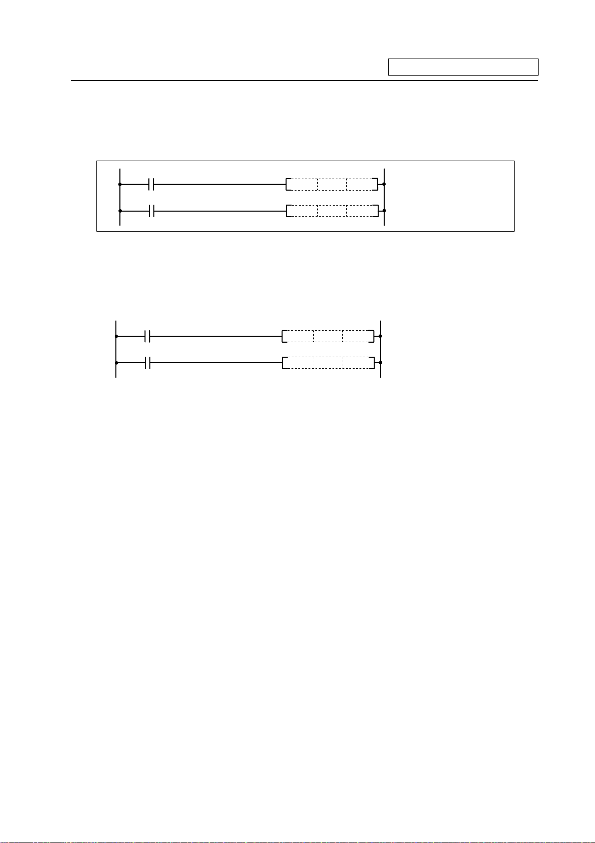
6.2.4 Index Ornament
(1) The index ornament is used to add an index (Z0, Z1) to a device, add the details of the directly
designated device No. and index register, and designate the device No.
(2) The index (Z0, Z1) can be set between -32768 to 32767 with a sign added.
(3) The index ornament is used only for the MOV command. (It cannot be used for DMOV.)
(4) The usable command format is shown below.
(a) Transmission of data to Z0, Z1
MOV Kn Z0
MOV
Use Kn or Hn
Z0 or Z1
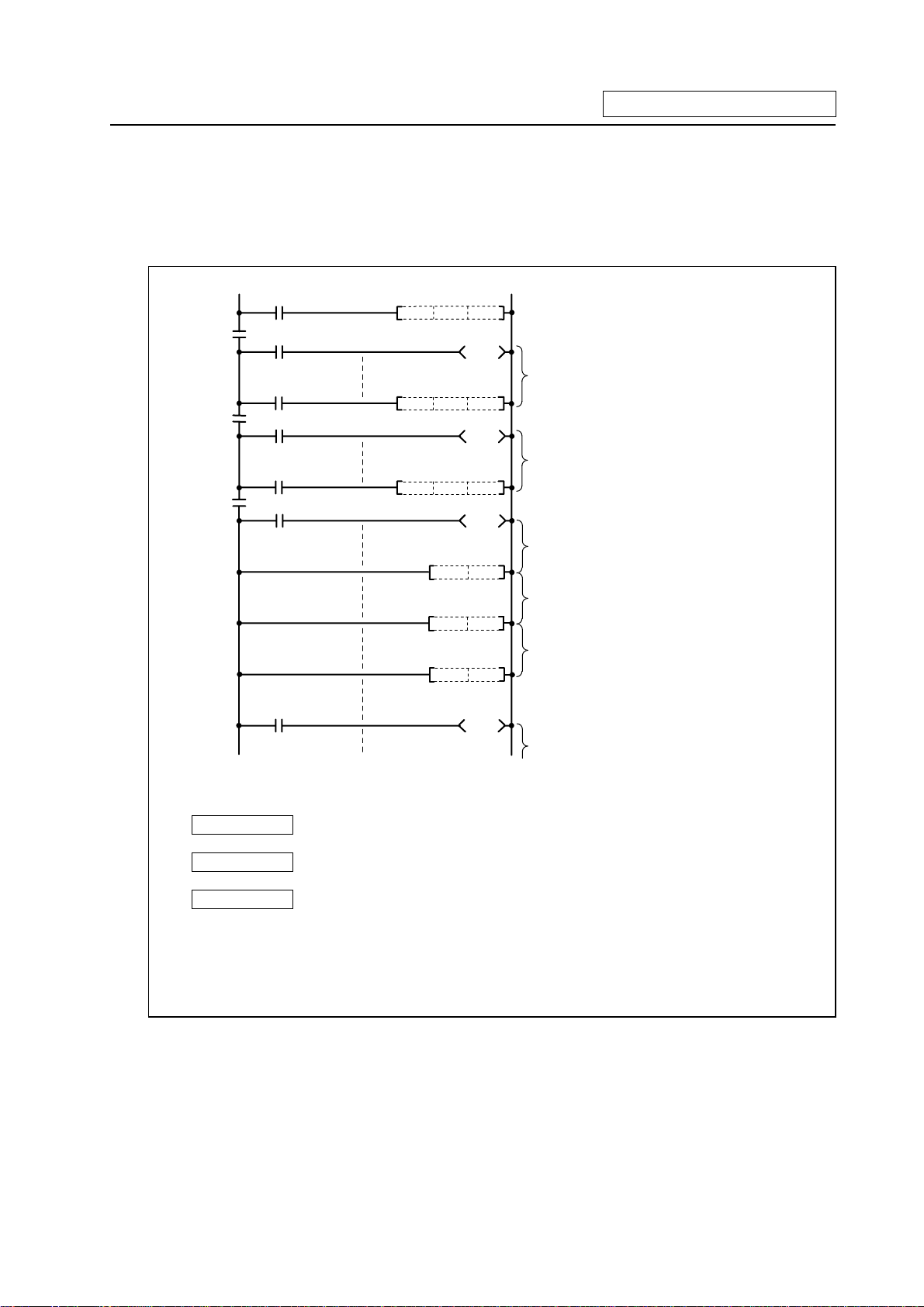
(b) Possible device combinations of MOV command with index ornament
Constant
Word device
MOV
Bit designation
S (source) D (destination) Program example
Kn or Hn
Example) D0, R1900
(Word device) ⋅ Z
Example) D0Z0
(Word device) ⋅ Z
Example) D0Z0
Example) K2M00
(Word device) ⋅ Z
Example) D0Z0, R500Z1
(Word device) ⋅ Z
Example) D0Z0, R500Z1
(Word device) ⋅ Z
Example) D1Z0, D0Z1
Bit designation
Example) K2Y20
(Word device) ⋅ Z
Example) D0Z0,
MOV K100 D0Z0
MOV D0 D100Z1
MOV D0Z0 D20Z0
MOV D0Z0 K2M10
MOV K2M10 D0Z0
R1900Z1
(Note 1) The word device refers to T, C, D and R.
(Note 2) The display of the circuit with index ornament is as shown below.
Z0
MOV D0
Z1
D20
- 36 -
Page 44

6. Explanation of Commands
6.2.5 Digit Designation
A digit may need to be designated for the bit device (X, Y, M, L, SM, F) when using the function
command. How many points of 4-point unit bit devices are to be used with the 16-bit or 32-bit
command is selected with this digit designation.
Use device K when designating the digit. The designation range is as shown below. A random bit
device can be set for the bit device.
(a) 16-bit command: K1 to 4 (4 to 16 points)
(Example) Setting range with digit designation of X0 to F 16-bit data
X0X3X4X8 X7XC XBXF
K1 designation range
(4 points)
K2 designation range
(8 points)
K3 designation range
(12 points)
K4 designation range
(16 points)
(b) 32-bit command: K1 to 8 (4 to 32 points)
(Example) Setting range with digit designation of X0 to 1F 32-bit data.
K 2 de s i gna ti on rang e
(8 points )
K3 designation range
(12 points)
K4 designation range
(16 points)
K 5 de s i gna ti on rang e
(20 points)
K 6 designa tion r ang e
(24 points)
K7 designation range
(28 points)
X0X3X4X8 X7XCXBXFX10X13X14X18 X17X1C X1BX1F
K 1 de s i gna ti on rang e
(4 points )
K8 designation range
(32 points)
- 37 -
Page 45

6. Explanation of Commands
(1) When a digit is designated on the source (S) side, the values that can be handled as source data
will be as shown below.
Table of digit designations and values that can be handled
For 16-bit command For 32-bit command
K1 (4 points) 0~15 0~15
K2 (8 points) 0~255 0~255
K3 (12 points) 0~4095 0~4095
K4 (16 points) -32768~32767 0~65535
K5 (20 points) — 0~1048575
K6 (24 points) — 0~167772165
K7 (28 points) — 0~268435455
K8 (32 points) — -2147483648~2147483647
Program example Process
For 16-bit command
For 32-bit command
MOV
K1X0 D0
Source (S) data
B15
D0 0 0
0000000000
Becomes 0
....................................................
Becomes 0
....................................................
DMOV
K1X0 D0
Source (S) data
B15
D0
000000 X1X0X2X3000000
D1
0000000000000000
.........................................................................
B31
K1X0
Becomes 0
X2X3
B4 B3 B2 B1 B0
X2X3
K1X0
B4 B3 B2 B1 B0
X1X0
X1X0
X1X0X2X3
B16
- 38 -
Page 46

6. Explanation of Commands
(2) When a digit is designated on the destination (D) side, the No. of points designated by the digit
will be the target of the destination side.
Circuit side Process
When source data (S) is a value
1234
MOV H1234
K2M0
Destination (D) side
When source data (S) is a bit device
(Note)
MOV K1M0 K2M100
Destination (D) side
When source data (S) is a word device
H1234
K2M0
K1M0
K2M100
000100 0010100011
...................................
M15
Does not change
M15
M8
...................................
M8 M7
M7
34
1110101010011101
..................................
M115
M108M107
....... .........
M104M103
00001101
Does not change
0 is transmitte d
The M3 to M0 data
is transmitted
................................ ..................................
B15
D0
1
11 010 0111101001
M0
00100011
M0
M100
B0B8 B7
MOV
D0 K2M100
Destination (D) side
K2M100
...............................
M115
Does not change
(Note) The display of the circuit having a digit designation will be as follows.
K1
MOV M0 M100
K2
- 39 -
M108M107
................................
M100
01111001
Page 47

- 40 -
Page 48

7. Basic Commands
7. Basic Commands
These commands are the basis for the sequence programs. The sequence program cannot be
created without these commands.
The circuit can be created (programmed) with the same image as creating a circuit by combining the
actual relay A contacts and B contacts as done conventionally.
- 41 -
Page 49

{ LD, LDI ... Operation start
LD, LDI
Usable device
Bit device
X Y M L SM F T C D R Z K H P N
Word device
1
Constant
Pointer Level
X9
LD
X9
LDI
Device No.
Digit
desig-
nation
No. of
steps
Index
Function
LD is the A contact operation start command and LDI is the B contact operation start command. The
ON/OFF information of the designated device is read in as the operation results.
Execution conditions
This is executed per scan regardless of the device ON/OFF setting.
- 42 -
Page 50

Program example
(1) Program used at head of circuit block.
Coding
M32
10
M32
12
Y10
Y11
(2) Program used at head of circuit block connected with ANB.
Coding
99
ANB
X0
M9
M13
M35
Circuit block
connected with ANB.
Y99
(3) Program used at head of circuit block connected with ORB.
Coding
M1
X8
93
X12 M60
ORB
Circuit block
connected with ORB.
M99
No. of
steps
No. of
steps
No. of
steps
LD, LDI
Command
Device
10 LD M32
11 OUT Y10
12 LDI M32
13 OUT Y11
14
Command
Device
99 LD X0
100 LD M9
101 AND M13
102 ORI M35
103 ANB
104 OUT Y99
105
Command
Device
93 LD X8
94 AND M1
95 LD X12
96 ANI M60
97 ORB
98 OUT M99
99
- 43 -
Page 51

{ AND, ANI ... Serial connection of contact
AND, ANI
Usable device
Bit device
X Y M L SM F T C D R Z K H P N
Word device
1
Constant
Pointer Level
X0
AND
X0
ANI
Device No.
Digit
desig-
nation
No. of
steps
Index
Function
AND is the A contact serial connection command, and ANI is the B contact serial connection
command. The ON/OFF information of the designated device is read in, and the AND operation with
the operation results up to that point is executed. The result is the operation result.
Execution conditions
This is executed per scan regardless of the operation results before the AND, ANI commands.
- 44 -
Page 52

Program example
(1) Program used after LD, LDI, AND or ANI, etc.
Coding
M6
X3 Y33
10
M7
X4
X5
17
ANB
(2) Program used to connect contact in parallel with coil.
Coding
X5
93
X8
M9
M9
ORB
M11M8
Y34
Y35
Y36
X9
Y37
AND, ANI
No. of
steps
Command
Device
10 LD X3
11 AND M6
12 LDI X4
13 ANI M7
14 ORB
15 ANI M9
16 OUT Y33
17 LD X5
18 LD M8
19 OR M9
20 ANB
21 ANI M11
22 OUT Y34
23
No. of
steps
Command
Device
93 LD X5
94 OUT Y35
95 AND X8
96 OUT Y36
97 ANI X9
98 OUT Y37
99
- 45 -
Page 53

{ OR, ORI ... Parallel connection of one contact
OR, ORI
Usable device
Bit device
X Y M L SM F T C D R Z K H P N
Word device
1
Constant
Pointer Level
Device No.
OR
X0
ORI
X0
Digit
desig-
nation
No. of
steps
Index
Function
OR is the one A contact parallel connection command, and ORI is the one B contact parallel
connection operation command. The ON/OFF information of the designated device is read in, and the
OR operation with the operation results up to that point is executed. The result is the operation result.
Execution conditions
This is executed per scan regardless of the operation results before the OR, ORI commands.
- 46 -
Page 54

Program example
(1) Program used at head of circuit block.
Coding
X3
10
X4
X5
X5
14
X6
M11 Y34
(2) Program used in circuit.
Coding
M8X5 Y35
93
M9
M10
X6 M111
99
M113 Y36
M105
L10
Y33
OR, ORI
No. of
steps
Command
Device
10 LD X3
11 OR X4
12 OR X5
13 OUT Y33
14 LD X5
15 AND M11
16 ORI X6
17 OUT Y34
18
No. of
steps
Command
Device
93 LD X5
94 LD M8
95 OR M9
96 ORI M10
97 ANB
98 OUT Y35
99 LD X6
100 LD M111
101 ANI M113
102 OR M105
103 OR L10
104 ANB
105 OUT Y36
106
- 47 -
Page 55

{ ANB ... Serial connection of circuit block
ANB
Usable device
Bit device
X Y M L SM F T C D R Z K H P N
1
Word device
Constant
Pointer Level
Digit
desig-
nation
No. of
steps
Index
ANB
A block
B block
Function
(1) AND operation of the A block and B block is executed, and the operation results are obtained.
(2) The ANB symbol is a connection symbol instead of a contact symbol.
(3) When consecutively writing ANB, a max. of 7 commands (8 blocks) can be written. The PC
cannot execute a correct operation if 8 or more commands are written consecutively.
- 48 -
Page 56

Program example
Program that serially connects continuous circuit blocks.
ANB
10
X0
X1
X2
X3
X4
X5
X6
X7
X8
X9
M7
Coding
No. of
steps
Command
Device
10 LD X0
11 OR X1
12 LD X2
13 OR X3
14 ANB
15 LD X4
16 OR X5
17 ANB
18 LD X6
19 OR X7
20 ANB
21 LD X8
22 OR X9
23 ANB
24 OUT M7
25
- 49 -
Page 57

{ ORB ... Parallel connection of blocks
ORB
Usable device
Bit device
X Y M L SM F T C D R Z K H P N
1
Word device
Constant
Pointer Level
Digit
desig-
nation
No. of
steps
Index
A block
B block
OR or ORI is used for
the one contact
parallel connection.
ORB
Function
(1) OR operation of the A block and B block is executed, and the operation results are obtained.
(2) ORB connects circuit blocks with two or more contacts in parallel. Use OR or ORI to connect
circuit blocks with only one contact in parallel.
Coding
Y10
10
X2
X1X0
X3
No. of
steps
Command
Device
10 LD X0
11 AND X1
X4
12 LD X2
13 AND X3
14 ORB
15 ORI X4
16 OUT Y10
17
(3) The ORB symbol is a connection symbol instead of a contact symbol.
(4) When consecutively writing ORB, a max. of 7 commands (8 blocks) can be written. The PC
cannot execute a correct operation if 8 or more commands are written consecutively.
- 50 -
Page 58

Program example
Program that connects continuous circuit blocks in parallel.
Coding
X1
X0
10
X3
X2
X5
X4
X6
X7
M7
ORB
No. of
steps
Command
Device
10 LD X0
11 AND X1
12 LD X2
13 AND X3
14 ORB
15 LD X4
16 AND X5
17 ORB
18 LD X6
19 AND X7
20 ORB
21 OUT M7
22
- 51 -
Page 59

{ OUT (Y, M, L, SM, F) ... Output (Y, M, L, SM, F)
OUT (Y, M, L, SM, F)
Usable device
Bit device
X Y M L SM F T C D R Z K H P N
1
Word device
Constant
Pointer Level
Y35
M60
M61
F0
Digit
No. of
desig-
nation
steps
Device No.
Index
Function
The operation results before the OUT command are output to the designated device.
OUT command
Operation
results
Contact
Coil
A contact B contact
OFF OFF Non-continuity Continuity
ON ON Continuity Non-continuity
Execution condition
This is executed per scan regardless of the operation results before the OUT command.
- 52 -
Page 60

Program example
(1) Program output to output unit.
Coding
X5
10
X6 Y34
12
(2) Program that turns internal relay or latch relay ON/OFF.
Coding
X5
93
X5
95
X7 X8
100
Y33
Y35
M15
L19
M90
F0
OUT (Y, M, L, SM, F)
No. of
steps
Command
Device
10 LD X5
11 OUT Y33
12 LD X6
13 OUT Y34
14 OUT Y35
15
No. of
steps
Command
Device
93 LD X5
94 OUT M15
95 LDI X5
96 OUT L19
97 OUT M90
100 LD X7
101 AND X8
102 OUT F0
103
- 53 -
Page 61

{ OUT T ... Timer output
OUT T
Device
Setting
value
Usable device
Bit device
X Y M L SM F T C D R Z K H P N
Word device
Constant
Pointer Level
T0 K50
T0 D1 0
Digit
No. of
designation
Setting value
(1 to 32767 is valid)
Device No.(T0 to 255)
Setting value
(1 to 3276 7 is valid for
the data register details)
Device No.(T0 to 255)
steps
3
Index
Function
(1) When the operation results before the OUT command are ON, the timer coil will turn ON and
count to the set value. When the time is counted up (count value >= set value), the contacts will
change as shown below.
A contact Continuity
B contact Non-continuity
(2) If the operation results before the OUT command turn ON to OFF, the following will occur.
Timer type Timer coil
100ms timer
OFF
10ms timer
100ms integrated
timer
OFF
Timer current
value
0
Hold current
value
Before time up After time up
A contact B contact A contact B contact
Noncontinuity
Noncontinuity
Continuity Continuity
Continuity Continuity Non-
Noncontinuity
continuity
(3) The state of the integrated timer contact after time up will not change until the RST command is
executed.
- 54 -
Page 62

OUT T
Execution condition
This is executed per scan regardless of the operation results before the OUT command.
Program example
(1) Program to turn ON Y10 and Y14 ten seconds after X0 turns ON.
Coding
10
14
X0
T1
T1 K100
Y10
Y14
(2) Program to use X10 to 1F BCD data as timer setting value.
X0
T2 D1 0
Y15
D10
The X10 to 1 F data is B I N con verted an d s t o r ed in D10.
If X2 t u r n s O N, th e da t a stored in D1 0 will be c ou n t ed
as th e s et t i ng val ue .
When T2 counts up, Y15 will turn ON.
10
14
18
X2
T2
BIN K4X1
0
No. of
steps
Command
10 LD X0
11 OUT T1 K100
14 LD T1
15 OUT Y10
16 OUT Y14
17
Device
Coding
No. of
steps
Com mand
Device
10 LD X0
11 BIN K4X10 D10
14 LD X2
15 OUT T2 D10
18 LD T2
19 OUT Y15
20
- 55 -
Page 63

{ OUT C ... Counter output
OUT C
Device
Setting
value
Usable device
Bit device
X Y M L SM F T C D R Z K H P N
Word device
Constant
Pointer Level
C0 K50
C1 D10
Digit
No. of
designation
Setting value
(1 to 32767 is valid)
Device No.(C0 to 127)
Setting value
(1 to 32767 is valid for
the data register details)
steps
3
Index
Device No.(C0 to 127)
Function
(1) If the operation results before the OUT command change from OFF to ON, the current value
(count value) will be incremented by one. When the value is counted up (current value >= setting
value), the contacts will change as shown below.
A contact Continuity
B contact Non-continuity
(2) The value will not be counted when the operation results are ON. (A pulse change is not required
to input the count.)
(3) If the operation results change from OFF to ON after the "current value >= setting value" is
established, the contact state will remain the same, however the current value will be
incremented by 1.
Execution condition
This is executed per scan regardless of the operation results before the OUT command.
- 56 -
Page 64

OUT C
Program example
(1) Program to turn Y30 ON when X0 turns ON ten times, and to turn Y30 OFF when X1 turns ON.
Coding
X0
10
C10
14
X1
16
C10 K10
Y30
RST C10
No. of
steps
Command
Device
10 LD X0
11 OUT C10 K10
14 LD C10
15 OUT Y30
16 LD X1
17 RST C10
19
(2) Program to set C10 setting value to 10 when X0 turns ON, and to 20 when X1 turns ON.
X0
10
14
18
22
X1
X3
C10
MOV K10
MOV
K20 D0
C10 D0
Y30
D0
10 is stor ed i n D 0 w h en X 0 tu rns O N .
20 is stor ed i n D 0 w h en X 1 tu rns O N .
C10 c ounts t h e data s t ored i n D0 a s th e s ett i n g val u e.
Y30 turns ON when C10 counts up.
Coding
22 LD C10
23 OUT Y30
24
No. of
steps
Command
Device
10 LD X0
11 MOV K10 D0
14 LD X1
15 MOV K20 D0
18 LD X3
19 OUT C10 D0
- 57 -
Page 65

{ SET ... Device setting (ON)
SET
Bit device
X Y M L SM F T C D R Z K H P N
D
Usable device
Word device
Constant
Pointer Level
Setting command
SET
D
Digit
designation
Setting data
Device N0. to
D
be set (ON)
No. of
steps
Index
1
Function
(1) The designated device turns ON when the SET input turns ON.
(2) The device turned ON remains ON even if the SET input turns OFF. The device can be turned
OFF with the RST command.
ON
OFF
X5
SET Y10
X7
RST Y10
X5
X7
Y10
OFF
OFF
ON
ON
(3) If the SET input is OFF, the state of the device will not change.
Execution condition
The execution conditions for the SET command are as shown below.
ON
SET input
SET (Y, M, L, SM, F)
OFF
Executed per scan
Executed per scan
- 58 -
Page 66

SET
Program example
(1) Program to set Y8B (ON) when X8 turns ON, and reset Y8B (OFF) when X9 turns ON.
Coding
X9
Y8B
10
X8
12
RST
SET
Y8B
No. of
steps
Command
Device
10 LD X9
11 RST Y8B
12 LD X8
13 SET Y8B
14
ON
X8 (SET input) OFF
ON
X9 (RST input) OFF
ON
Y8B OFF
Operation of SET and RST commands
- 59 -
Page 67

{ RST ... Device resetting
RST
Bit device
X Y M L SM F T C D R Z K H P N
D
Usable device
Word device
Constant
Pointer Level
Reset command
RST
D
Digit
designation
Setting data
Device No. to
D
be reset
No. of
steps
1/2
Index
Function
(1) The designated device will change as explained below when the RST input turns ON.
Device Status
Y, M, L, SM, F
The coil and contact are turned OFF.
T, C 0 is set for the current value, and the coil and
contact are turned OFF.
(2) If the RST input is OFF, the state of the device will not change.
Execution condition
The execution conditions for the RST command are as shown below.
ON
RST input OFF
RST
Executed per scan Executed per scan
- 60 -
Page 68

Program example
(1) Program to reset 100ms integrated timer and counter.
10
14
X4
T96 K18000
T96
C23 K16
When T96 is set for the integrated timer,
T96 will t urn ON when the X4 ON t ime is 30 m in.
The No. of times that T96 turns ON is counted.
RST
20
22
C23
X5
RST T96
Y55
RST C23
T96 is reset when T96 turns ON.
Y55 turns ON when C23 counts up.
C23 is r eset when X5 t urns ON.
Coding
2 steps are used for T or C device.
1 step is used for the other devices.
No. of
steps
Com-
mand
Device
10 LD X4
11 OUT T96 K18000
14 LD T96
15 OUT C23 K16
18 RST T96
20 LD C23
21 OUT Y55
22 LD X5
23 RST C23
25
- 61 -
Page 69

{ MC, MCR ... Master control set/reset
MC, MCR
Bit device
X Y M L SM F T C D R Z K H P N
n
D
Usable device
Word device
Constant
Pointer Level
MC ON/OFF command
n
MCR n
n
D device
Nesting (N0 to 7)
MC
Digit
No. of
designation
D
Setting data
Nesting
n
(N0 to 7)
Device No. to
D
be turned ON
steps
2/1
Index
Function
MC
(1) If the MC ON/OFF command is ON when the master control starts, the operation results between
MC and MCR will remain the same.
(2) If the MC ON/OFF command is OFF, the operation results between MC and MCR will be as
follows.
100ms, 10ms
timer
Count value is set
to 0
100ms integrated timer counter
Current count value is held
OUT
command
All become
OFF
SET/RST SFT
The state is
retained
(3) Up to eight (N0 to 7) nests can be used. When using nests, the MC will use the nesting (N) from
the smallest No., and MCR will use from the largest No.
(4) The program between the MC command and MCR command will be scanned regardless of the
MC command ON/OFF state.
(5) By changing the destination D device, the MC command can be used as often as necessary in
one scan.
(6) When the MC command is ON, the coil for the device designated for the destination will turn ON.
- 62 -
Page 70

MC, MCR
MCR
(1) This is the master control cancel command, and indicates the end of the master control range.
(2) The designated nesting (N) No. and following nests will be canceled.
MCR
N3
N3 to N7 master control is canceled.
Program example
(1) Program to turn MC ON when X9 is ON and turn MC OFF when OFF.
X9
10
N0
13
15
17
19
21
M98
X10
X11
X12
X13
MC M98N0
MCR
Y30
Y31
Y32
Y33
N0
Control range of
Coding
No. of
steps
10 LD X9
11 MC N0 M98
13 LD X10
14 OUT Y30
15 LD X11
16 OUT Y31
17 LD X12
18 OUT Y32
19 LD X13
20 OUT Y33
21 MCR N0
22
MC M98N0
Command
Device
- 63 -
Page 71

{ PLS, PLF ... Pulse (1 scan ON)
PLS, PLF
Bit device
X Y M L SM F T C D R Z K H P N
D
Usable device
Word device
Constant
Pointer Level
Digit
designation
No. of
steps
Index
2
PLS command
PLS
PLF
PLS
PLF command
PLF D
D
Setting data
Device No. to
D
be pulse coded
Function
PLS
(1) The designated device is turned ON for one scan when the PLS command changes from OFF to
ON and is turned OFF in all other cases.
X5
PLS M0
X5M0OFF
ON
ON
OFF
1 scan
1 scan
(2) Even if the sequence program is changed from RUN to STOP and then RUN after the PLS
command is executed, the PLS command will not be executed. If the PLS command is ON when
the power is turned ON, the PLS command will be executed.
PLF
(1) The designated device is turned ON for one scan when the PLF command changes from ON to
OFF and is turned OFF in all other cases.
X5
PLF
M0
X5M0OFF
OFF
ON
1 scan
ON
1 scan
(2) Even if the sequence program RUN switch is changed from RUN to STOP and then RUN after
the PLF command is executed, the PLF command will not be executed.
- 64 -
Page 72

Program example
(1) Program to execute PLS command when X9 turns ON.
Coding
X9
PLS
10
X9 O FF
M9 O FF
M9
ON
ON
PLS, PLF
No. of
steps
Command
Device
10 LD X9
11 PLS M9
13
1 scan
(2) Program to execute PLF command when X9 turns OFF.
Coding
X9
10
PLF
M9
ON
X9 O FF
M9 O FF
No. of
steps
10 LD X9
Command
Device
11 PLF M9
13
ON
1 scan
- 65 -
Page 73

{ SFT ... Device shift
SFT
Bit device
X Y M L SM F T C D R Z K H P N
D
Usable device
Word device
Constant
Pointer Level
Digit
No. of
designation
4
steps
Index
SFT command
SFT
Setting data
D
SFT D
Device No. to
be shifted
Function
(1) The device that designates the ON/OFF state of the device that is one number smaller than the
device designated with D (destination) is shifted, and the device that is one number smaller is
turned OFF.
(2) Turn the head device to be shifted ON with the SET command.
(3) When using SFT in succession, program from the largest device No.
(Pulse cod i ng)
M0
X02
Shift input
M15M14
M13M12M11M10 M9 M8
SFT M14
SFT
M13
SFT M12
M11
SFT
SET M10
* In M8 to 15, "1" indicates ON and "0" indicates OFF.
1
00000 0
2
0000 0 0
3
000 000
4
5
6
11
00 000 0
11
000000
000000 0
11
11
11
1
Operation of shift command
State before initial shift
After 1st shift input
After 2nd shift input
After 3rd shift input
After 4th shift input
After 5th shift input
- 66 -
Page 74

Execution condition
The execution conditions for the SFT command are as shown below.
ON
SFT input OFF
SFT command
Executed per scan Executed per scan
Program example
(1) Program to shift Y57 to 5B when X8 turns ON.
X8
PLS
6
M0
9
(pules coding)
M0
SFT
Y5B
SFT Y5A
SFT Y59
Shifting is executed when M0 turns ON.
(program from the largest device No.)
SFT
SFT Y58
26
29
X7
PLS M8
M8
SET Y57
Coding
M0
X7
Y57
Y58
Y59
Y5A
Y5B
X57 is turned ON when X7 turns ON.
No. of
steps
Command
Device
6 LD X8
7 PLS M0
9 LD M0
10 SFT Y5B
14 SFT Y5A
18 SFT Y59
22 SFT Y58
26 LD X7
27 PLS M8
29 LD M8
30 SET Y57
31
- 67 -
Page 75

{ MPS, MRD, MPP ... Registering, reading and clearing of operation results
MPS, MRD, MPP
Usable device
Bit device
X Y M L SM F T C D R Z K H P N
1
Word device
Constant
Pointer Level
Digit
desig-
nation
No. of
steps
Index
MPS, MRD and MPP are not displayed.
MPS
MRD
MPP
Function
MPS
(1) The operation results (ON/OFF) just before the MPS command are registered.
(2) The MPS command can be used consecutively up to four times. If the MPP command is used in
between, the No. of MPS usages will be decremented by one.
MRD
(1) The operation results registered with the MPS command are read, and the operation is continued
from the next step using those operation results.
MPP
(1) The operation results registered with the MPS command are read, and the operation is continued
from the next step using those operation results.
(2) The operation results registered with the MPS command are cleared.
- 68 -
Page 76

Point
(1) The circuits when MPS, MRD and MPP are used and not used are as follow.
Circ uit using MPS , MRD a nd MPP Cir cuit not us ing MPS, MRD and MP P
X1
X0 X2
X1X0
X1X0
10
X0
X1
X2
X3
X5
X4
Y10
10
Y11
14
Y12
19
X3 X4
X5
MPS, MRD, MPP
Y10
Y11
Y12
(1) Program using MPS, MRD and MPP.
Coding
No. of
steps
10 LD X1C
11 MPS
(a)
12 AND M8
13 OUT Y30
(b)
14 MPP
15 OUT Y31
16 LD X1D
(c)
17 MPS
18 ANI M9
19 MPS
(d)
20 AND M68
21 OUT Y32
(e)
22 MPP
23 AND T0
24 OUT Y33
(f)
25 MPP
26 OUT Y34
27 LD X1E
28 AND M81
(g)
29 MPS
30 AND M96
31 OUT Y35
(h)
32 MRD
33 AND M97
34 OUT Y36
(i)
35 MRD
36 AND M98
37 OUT Y37
(j)
38 MPP
39 OUT Y38
40
10
16
27
X1C
X1D Y32
M8
(a)
(b)
M9
(c) (d)
(f)
M81X1E
(g)
(h)
(i)
(j)
(e)
M96
M97
M98
M68
T0
Y30
Y31
Y33
Y34
Y35
Y36
Y37
Y38
Command
Device
- 69 -
Page 77

DEFR ... Pulses in regard to operation results
DEFR
Bit device
X Y M L SM F T C D R Z K H P N
D
Usable device
Word device
Constant
Pointer Level
DEFR command
D
(Not e)
Setting data
D
Digit
No. of
designation
1
Operation memory for
generating one scan worth
of pulses
steps
Index
(Note) In programming with the MELSEC PLC development tool (GX Developer),
"AND" comm and is substituted and used.
Function
The operation results are turned ON for one scan when the DEFR command is turned from OFF to
ON, and are turned OFF for all other cases.
X5
M0
M1
X5 OFF
M0 OFF
M1 OFF
ON
ON
ON
1 scan
1 scan
Execution conditions
This is executed per scan regardless of the operation results to the DEFR command.
- 70 -
Page 78

Program example
(1) Program to turn Y0 ON for one scan when X9 turns ON.
Coding
X9
10
M0
Y0
ON
X9 O FF
ON
DEFR
No. of
steps
Com mand
Device
10 LD X9
11 ANDP M0
12 OUT Y0
13
Y0 O FF
1 scan
(2) Program to execute MOV command once when X9 turns ON.
Coding
10
X9
M0
MOV
K0
D10
No. of
steps
10 LD X9
11 ANDP M0
12 MOV K0 D10
15
Com mand
Device
- 71 -
Page 79

- 72 -
Page 80

8. Function Commands
8. Function Commands
Recent sequence programs that require more advanced control cannot provide sufficient control only
with basic commands and thus need four-rule operation and comparison, etc.
Many function commands have been prepared for this. There are approx. 76 types of function
commands.
Each command is explained in the following section.
- 73 -
Page 81

{ LD=, AND=, OR= .... Comparison of 16-bit data (=)
LD=, AND=, OR=
Usable device
Bit device Word device
X Y M L SM F T C D R Z K H P N
S1
S2
Constant
Pointer Level
LD=
AND=
OR=
= S2S1
S1
= S2
Digit
designation
Setting data
S1
S2
No. of
Comparison data or
No. of device where
comparison data is
stored.
Index
steps
3
= S2
S1
Function
(1) 16-bit comparison operation is executed with "A" contact handling.
(2) The comparison operation results will be as follow.
Conditions Comparison operation results
S1=S2 Continuity state
S1=/S2
Non-continuity state
Execution conditions
The execution conditions for LD=, AND= and OR= are as follow.
Command Execution conditions
LD= Executed per scan
AND= Executed only when previous
contact command is ON
OR= Executed per scan
- 74 -
Page 82

Program example
(1) Program to compare the X0 to F data and D3 data.
Coding
Y33
10
(2) Program to compare the BCD value 100 and D3 data.
Coding
10
(3) Program to compare the BIN value 100 and D3 data.
Coding
10
(4) Program to compare the D0 and D3 data.
Coding
10
= D3K4X0
M3
M3
M8
M3
= D3
=D3H100
=
D0
Y33
Y33
D3K100
M8
Y33
LD=, AND=, OR=
No. of
steps
Command
Device
10 LD= K4X0 D3
13 OUT Y33
14
No. of
steps
Command
Device
10 LD M3
11 AND= H100 D3
14 OUT Y33
15
No. of
steps
Command
Device
10 LD M3
11 LD= K100 D3
14 OR M8
15 ANB
16 OUT Y33
17
No. of
steps
Command
Device
10 LD M3
11 AND M8
12 OR= D0 D3
15 OUT Y33
16
- 75 -
Page 83

{ LDD=, ANDD=, ORD= ... Comparison of 32-bit data (=)
LDD=, ANDD=, ORD=
Usable device
Bit device Word device
X Y M L SM F T C D R Z K H P N
S1
S2
Constant
Pointer Level
LDD =
ANDD=
ORD=
D= S2S1
D=
S2S1
Digit
designation
Setting data
S1
S2
No. of
Comparison data or
head No. of device
where comparison
data is stored.
Index
steps
3/4
D=
S1
S2
Function
(1) 32-bit comparison operation is executed with "A" contact handling.
(2) The comparison operation results will be as follow.
Conditions Comparison operation results
S1=S2 Continuity state
S1=/S2
Non-continuity state
Execution conditions
The execution conditions for LDD=, ANDD= and ORD= are as follow.
Command Execution conditions
LDD= Executed per scan
ANDD= Executed only when previous
contact command is ON
ORD= Executed per scan
- 76 -
Page 84

Program example
(1) Program to compare the X0 to 1F data, D3 and D4 data.
Coding
10
D=
D3K8X0
Y33
(2) Program to compare the BCD value 18000, D3 and D4 data.
Coding
10
M3
D=D3H18000
Y33
(3) Program to compare the BIN value -80000, D3 and D4 data.
Coding
10
M3
D=
D3K-80000
M8
Y33
(4) Program to compare the D0, D1, D3 and D4 data.
No. of
steps
10 LDD= K8X0 D3
13 OUT Y33
14
No. of
steps
10 LD M3
11
15 OUT Y33
16
No. of
steps
10 LD M3
11 LDD=
15 OR M8
16 ANB
17 OUT Y33
18
LDD=, ANDD=, ORD=
Com-
mand
Com-
mand
ANDD= H18000
Com-
mand
K-80000
Device
Device
D3
Device
D3
Coding
M8
10
M3
D=
D3D0
Y33
- 77 -
No. of
steps
Com-
mand
Device
10 LD M3
11 AND M8
12 ORD= D0 D3
15 OUT Y33
16
Page 85

{ LD>, AND>, OR> .... Comparison of 16-bit data (>)
LD>, AND>, OR>
Usable device
Bit device Word device
X Y M L SM F T C D R Z K H P N
S1
S2
Constant
Pointer Level
S1
S1
S1
S2
S2
S2
LD>
AND>
OR>
>
>
>
Function
(1) 16-bit comparison operation is executed with "A" contact handling.
(2) The comparison operation results will be as follow.
Digit
No. of
desig-
steps
nation
Setting data
Comparison data or
S1
No. of device where
comparison data is
S2
stored.
Index
3
Conditions Comparison operation results
S1>S2 Continuity state
S1<=S2 Non-continuity state
Execution conditions
The execution conditions for LD>, AND> and OR> are as follow.
Command Execution conditions
LD> Executed per scan
AND> Executed only when previous
contact command is ON
OR> Executed per scan
- 78 -
Page 86

Program example
(1) Program to compare the X0 to F data and D3 data.
Coding
10
>
K4X0
D3
(2) Program to compare the BCD value 100 and D3 data.
Coding
10
H100
>
D3
(3) Program to compare the BIN value 100 and D3 data.
Coding
M3
10
K100
>
D3
M8
(4) Program to compare the D0 and D3 data.
Coding
M3
10
M8
> D3D0
Y33
Y33M3
Y33
Y33
LD>, AND>, OR>
No. of
steps
Com-
mand
Device
10 LD> K4X0 D3
13 OUT Y33
14
No. of
steps
Com-
mand
Device
10 LD M3
11 AND> H100 D3
14 OUT Y33
15
No. of
steps
Com-
mand
Device
10 LD M3
11 LD> K100 D3
14 OR M8
15 ANB
16 OUT Y33
17
No. of
steps
Com-
mand
Device
10 LD M3
11 AND M8
12 OR> D0 D3
15 OUT Y33
16
- 79 -
Page 87

{ LDD>, ANDD>, ORD> ... Comparison of 32-bit data (>)
LDD>, ANDD>, ORD>
Usable device
Bit device Word device
X Y M L SM F T C D R Z K H P N
S1
S2
Constant
Pointer Level
LDD>
AND D>
ORD>
D>
D>
D> S2S1
S1
S2S1
S2
Function
(1) 32-bit comparison operation is executed with "A" contact handling.
(2) The comparison operation results will be as follow.
Digit
No. of
desig-
steps
nation
3/4
Setting data
Comparison data or
S1
head No. of device
where comparison
S2
data is stored.
Index
Conditions Comparison operation results
S1>S2 Continuity state
S1<=S2 Non-continuity state
Execution conditions
The execution conditions for LDD>, ANDD> and ORD> are as follow.
Command Execution conditions
LDD> Executed per scan
ANDD> Executed only when previous
contact command is ON
ORD> Executed per scan
- 80 -
Page 88

Program example
(1) Program to compare the X0 to 1F data, D3 and D4 data.
Coding
Y33
10 D>
K8X0
D3
(2) Program to compare the BCD value 18000, D3 and D4 data.
Coding
10
M3
D> D3
H18000
Y33
(3) Program to compare the BIN value -80000, D3 and D4 data.
Coding
M3
10 D> D3K-80000
M8
Y33
(4) Program to compare the D0, D1, D3 and D4 data.
Coding
M3 M8
10
D > D3D0
Y33
No. of
steps
10 LDD> K8X0 D3
13 OUT Y33
14
No. of
steps
10 LD M3
11
15 OUT Y33
16
No. of
steps
10 LD M3
11 LDD>
15 OR M8
16 ANB
17 OUT Y33
18
No. of
steps
10 LD M3
11 AND M8
12 ORD> D0 D3
15 OUT Y33
16
LDD>, ANDD>, ORD>
Com-
mand
Com-
mand
ANDD> H18000
Com-
mand
K-80000
Com-
mand
Device
Device
D3
Device
D3
Device
- 81 -
Page 89

{ LD<, AND<, OR< .... Comparison of 16-bit data (<)
LD<, AND<, OR<
Usable device
Bit device Word device
X Y M L SM F T C D R Z K H P N
S1
S2
Constant
Pointer Level
LD<
AND<
OR<
<
<
S1
<
S2S1
S2S1
S2
Function
(1) 16-bit comparison operation is executed with "A" contact handling.
(2) The comparison operation results will be as follow.
Digit
No. of
desig-
steps
nation
Setting data
Comparison data or
S1
No. of device where
comparison data is
S2
stored.
Index
3
Conditions Comparison operation results
S1<S2 Continuity state
S1>=S2 Non-continuity state
Execution conditions
The execution conditions for LD<, AND< and OR< are as follow.
Command Execution conditions
LD< Executed per scan
AND< Executed only when previous
contact command is ON
OR< Executed per scan
- 82 -
Page 90

Program example
(1) Program to compare the X0 to F data and D3 data.
LD<, AND<, OR<
Coding
Y33
10
K4X0
<
D3
(2) Program to compare the BCD value 100 and D3 data.
Coding
M3
<
10 D3
H100
Y33
(3) Program to compare the BIN value 100 and D3 data.
Coding
10
M3
<
D3K100
M8
Y33
(4) Program to compare the D0 and D3 data.
No. of
steps
Com-
mand
Device
10 LD< K4X0 D3
13 OUT Y33
14
No. of
steps
Com-
mand
Device
10 LD M3
11 AND< H100 D3
14 OUT Y33
15
No. of
steps
Com-
mand
Device
10 LD M3
11 LD< K100 D3
14 OR M8
15 ANB
16 OUT Y33
17
Coding
M8
M3
10
D0
<
D3
Y33
- 83 -
No. of
steps
Com-
mand
Device
10 LD M3
11 AND M8
12 OR< D0 D3
15 OUT Y33
16
Page 91

{ LDD<, ANDD<, ORD< ... Comparison of 32-bit data (<)
LDD<, ANDD<, ORD<
Usable device
Bit device Word device
X Y M L SM F T C D R Z K H P N
S1
S2
Constant
Pointer Level
LDD <
AND D<
ORD<
D< S2S1
D< S2
D< S2S1
S1
Function
(1) 32-bit comparison operation is executed with "A" contact handling.
(2) The comparison operation results will be as follow.
Digit
No. of
desig-
steps
nation
Setting data
Comparison data or
S1
head No. of device
where comparison
S2
data is stored.
Index
3/4
Conditions Comparison operation results
S1<S2 Continuity state
S1>=S2 Non-continuity state
Execution conditions
The execution conditions for LDD<, ANDD< and ORD< are as follow.
Command Execution conditions
LDD< Executed per scan
ANDD< Executed only when previous
contact command is ON
ORD< Executed per scan
- 84 -
Page 92

Program example
(1) Program to compare the X0 to 1F data, D3 and D4 data.
Coding
No. of
steps
10 LDD< K8X0 D3
13 OUT Y33
14
No. of
steps
10 LD M3
11
15 OUT Y33
16
No. of
steps
10 LD M3
11 LDD<
15 OR M8
16 ANB
17 OUT Y33
18
Coding
No. of
steps
10 LD M3
11 AND M8
12 ORD< D0 D3
15 OUT Y33
16
10
D<
D3K8X0
Y33
(2) Program to compare the BCD value 18000, D3 and D4 data.
Coding
10
M3
D< D3H18000
Y33
(3) Program to compare the BIN value -80000, D3 and D4 data.
Coding
10
M3
D< D3K-80000
M8
Y33
(4) Program to compare the D0, D1, D3 and D4 data.
M3
10
D<
M8
D3D0
Y33
LDD<, ANDD<, ORD<
Com-
mand
Com-
mand
ANDD< H18000
Com-
mand
K-80000
Com-
mand
Device
Device
D3
Device
D3
Device
- 85 -
Page 93

{+ ... BIN 16-bit addition
+
Usable device
Bit device Word device
X Y M L SM F T C D R Z K H P N
S1
S2
D
Constant
Pointer Level
Digit
designation
No. of
Index
steps
4
Setting data
Addition data or No. of device
Addition command
+
+ S2S1
D
S1
where addition data is stored.
Addition data or No. of device
S2
where addition data is stored.
No. of device to store addition
D
results.
Function
(1) The BIN data designated with S1 and the BIN data designated with S2 are added, and the
addition results are stored in the device designated with D.
+ S2S1 D
S1
S2 D
B15.....................B0
5678 (BIN) 1234 (BIN) 6912 (BIN)
B15.....................B0
+
B15.....................B0
(2) -32768 to 32767 (BIN 16-bit) can be designated in S1 and S2.
(3) The positive/negative of the data in S1, S2 and D is determined with the highest-order bit (B15).
B15
Judgment of
positive/negative
0 Positive
1 Negative
(4) The carry flag will not turn ON even if an overflow results.
- 86 -
Page 94

Execution conditions
The execution conditions for + are as shown below.
ON
Addition command OFF
+
+
Executed per scan
Executed per scan
Program example
(1) Program to add the D0 BIN data and D10 BIN data and output to D20.
Coding
M0
10
+
(ON)
D10D0D20
No. of
steps
Com-
mand
10 LD M0
11 + D0 D10 D20
15
Device
- 87 -
Page 95

{ D+ ... BIN 32-bit addition
D+
Usable device
Bit device Word device
X Y M L SM F T C D R Z K H P N
S1
S2
D
Constant
Pointer Level
Digit
designation
No. of
Index
steps
4/5
Setting data
Addition data or head No. of device
S1
where addition data is stored.
Addition data or head No. of device
S2
where addition data is stored.
Head No. of device to store addition
D
results.
D+
Addition command
D+
S2S1D
Function
(1) The BIN data designated with S1 and the BIN data designated with S2 are added, and the
addition results are stored in the device designated with D.
D+
S2S1 D
S1S1+1
S2S2+1 DD+1
B31......B16B15.......B0
567890 (BIN) 123456 (BIN) 691346 (BIN)
B31......B16B15.......B0
+
B31......B16B15.......B0
(2) -2147483648 to 2147483647 (BIN 32-bit) can be designated in S1 and S2.
(3) The positive/negative of the data in S1, S2 and D is determined with the highest-order bit (B31).
B31
0 Positive
1 Negative
(4) The carry flag will not turn ON even if an overflow results.
Judgment of
positive/negative
- 88 -
Page 96

Execution conditions
The execution conditions for D+ are as shown below.
ON
Addition command OFF
D+
D+
Executed per scan
Executed per scan
Program example
(1) Program to add the D0, 1 data and D9, 10 data when X0 turns ON, and output the results to D20,
21.
Coding
X0
10
D+D9D0
D20
No. of
steps
Com-
mand
Device
10 LD X0
11 D+ D0 D9 D20
15
- 89 -
Page 97

{ – ... BIN 16-bit subtraction
–
Usable device
Bit device Word device
X Y M L SM F T C D R Z K H P N
S1
S2
D
Constant
Pointer Level
Digit
designation
No. of
Index
steps
4
Setting data
Subtraction data or No. of device
Subtraction command
-
-
S1
S2
D
S1
where subtraction data is stored.
Subtraction data or No. of device
S2
where subtraction data is stored.
No. of device to store subtraction
D
results.
Function
(1) The device designated with S2 is subtracted From the device designated with S1, and the
subtraction results are stored in the device designated with D.
-
S1
S2
S1 S2
D
D
B15.....................B0
5678 (BIN) 1234 (BIN) 4444 (BIN)
B15.....................B0
-
B15.....................B0
(2) -32768 to 32767 (BIN 16-bit) can be designated in S1 and S2.
(3) The positive/negative of the data in S1, S2 and D is determined with the highest-order bit (B15).
B15
Judgment of
positive/negative
0 Positive
1 Negative
(4) The carry flag will not turn ON even if an underflow results.
- 90 -
Page 98

Execution conditions
The execution conditions for - are as shown below.
ON
Subtraction command OFF
–
-
Executed per scan
Executed per scan
Program example
(1) Program to subtract the BIN data D10 from D3 and output to D20.
Coding
M0
10
(ON)
-
D3 D20
D10
No. of
steps
Com-
mand
Device
10 LD M0
11 - D3 D10 D20
15
(2) Program to BCD output the difference of the timer T3 setting value and current value to D20.
Coding
X3
10
13
M0
MOV
(ON)
-
BCD D3
T3 K18000
K18000 D2
T3D2
D3
D20
No. of
steps
Com-
mand
Device
10 LD X3
11 OUT T3
K18000
13 LD M0
14 MOV
K18000
D2
17 - D2 T3 D3
21 BCD D3 D20
24
- 91 -
Page 99

{ D– ... BIN 32-bit subtraction
D–
Usable device
Bit device Word device
X Y M L SM F T C D R Z K H P N
S1
S2
D
Constant
Pointer Level
Digit
designation
No. of
Index
steps
4/5
Setting data
Subtraction data or head No. of device
S1
where subtraction data is stored.
Subtraction data or head No. of device
S2
where subtraction data is stored.
Head No. of device to store subtraction
D
results.
D-
Subtraction command
D-
S2S1
D
Function
(1) The device designated with S2 is subtracted from the device designated with S1, and the
subtraction results are stored in the device designated with D.
D-
S1
S2
D
S1+1
S1
S2S2+1
D+1
D
B31......B16B15.......B0
567890 (BIN) 123456 (BIN) 444434 (BIN)
B31......B16B15.......B0 B31......B16B15.......B0
-
(2) -2147483648 to 2147483647 (BIN 32-bit) can be designated in S1 and S2.
(3) The positive/negative of the data in S1, S2 and D is determined with the highest-order bit (B31).
B31
Judgment of
positive/negative
0 Positive
1 Negative
(4) The carry flag will not turn ON even if an underflow results.
- 92 -
Page 100

Execution conditions
The execution conditions for D- are as shown below.
ON
Subtraction command OFF
D–
D-
Executed per scan
Executed per scan
Program example
(1) Program to subtract the D0, 1 data from the D10, 11 data when X1 turns ON, and output the
results to D99, 100. Program to subtract the D0, 1 data from D10, 11 data when X2 turns ON, and
output the results to D97, 98.
10
15
X1
X2
D-D0D10
D-
D99
D0D10 D97
Subtract D0, 1 from D10,11,
and store the results in D99,100
Subtract D0, 1 from D10,11,
and store the results in D97,98
Coding
No. of
steps
Com-
mand
Device
10 LD X1
11 D- D10 D0 D99
15 LD X2
16 D- D10 D0 D97
20
- 93 -
 Loading...