

Mitsubishi DY-5MU4R69-T-3, DY-5MU4R69-T-4 Service Manual

SE060914083E Ver.pptx14E
CONTENTS
● DISASSEMBLING PROCEDURES ............................. 2~18
● PARTS LIST ................................................................. 19,20
● ELECTRICAL PARTS LIST ........................................ 21~36
DY-5MU4R69-T-3,4
2014 Oct.
MITSUBISHI MOTORS
SERVICE MANUAL
AM / FM-ST ELECTRONIC TUNING RADIO,
CD PLAYER
* Refer to the Service Manual for DY-5MU4R69-T,-2
(34U277, 34W894) unless otherwise stated in this.
Model : DY-5MU4R69-T-3 (For MMC)
DY-5MU4R69-T-4 (For MMNA)
MELCO Code : 34U587, 34W936
PART No. : 8701A587, 8701A587
MITSUBISHI ELECTRIC CORP. SANDA WORKS
Copyright (C) Mitsubishi Electric Corporation.
Your company internal use only.

DISASSEMBLING PROCEDURES
*It is assembling procedure. Disassembling procedure is in reverse.
DY-5MU4R69-T-3,4
M019(1)/M030(2) : LABEL
M020(1) : NAME-CARD(DY-5MU4R69-T-3)
M031(2) : NAME-CARD(DY-5MU4R69-T-4)
2
Mod el
(1)
DY-5MU4R69-T-3
(2)
DY-5MU4R69-T-4
Your company internal use only.Copyright (C) Mitsubishi Electric Corporation.

DISASSEMBLING PROCEDURES
● Disassembling procedures
In reverse of assembling procedures.
● Assembling procedures
1. Attach M025 to S2-CHASSIS.
DY-5MU4R69-T-3,4
S2-CHASSIS
M025 : ASSY-KNOB
3
Your company internal use only.Copyright (C) Mitsubishi Electric Corporation.
DISASSEMBLING PROCEDURES
● Disassembling procedures
In reverse of assembling procedures.
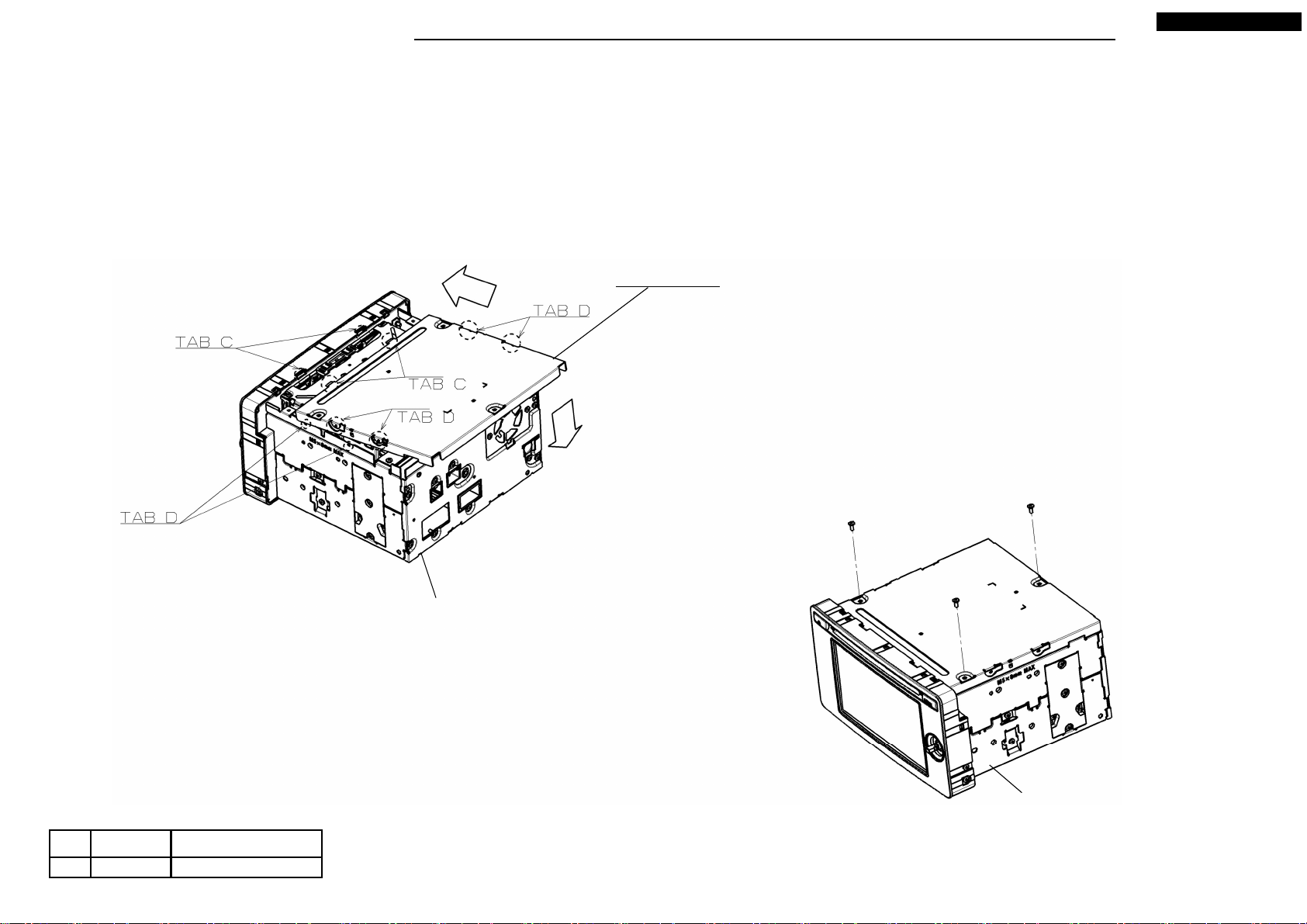
● Assembling procedures
1. Fit tab C of M012 on tab C of S2-CHASSIS (2 places) to direction arrow.
And fit tab D of M012. (4 places)
2. Screw S2-CHASSIS and M012 with Ⓔ. (3 places)
DY-5MU4R69-T-3,4
M012 : COVER
No. Screw
Ⓔ
2.6X6 0.5 +0.2/-0.1
Tighten torque(N・m)
S2-CHASSIS
4
Ⓔ x 3
S2-CHASSIS
Your company internal use only.Copyright (C) Mitsubishi Electric Corporation.

DISASSEMBLING PROCEDURES
● Disassembling procedures
In reverse of assembling procedures.
● Assembling procedures
1. Insert M003 to S2-DECK and PCB-MEDIA.
*Lock connector after inserting M003.
2. Positioning S2-DECK to S2-CHASSIS and fit S2-DECK to S2-CHASSIS.
*Handling range of S2-DECK is follow the indicates in view on left.
*Rearranging method is follow the indicates in view on right.
3. Screw S2-CHASSIS and S2-DECK with Ⓔ. (4 places)
DY-5MU4R69-T-3,4
Ⓔ x 4
S2-DECK
S2-DECK
M003 : FLAT-CABLE 18P
S2-CHASSIS
M003 S2-DECK
S2-CHASSIS
M003
S2-DECK
M003
S2-DECK
5
No. Screw
Ⓔ
2.6X6 0.5 +0.2/-0.1
Your company internal use only.Copyright (C) Mitsubishi Electric Corporation.
Tighten torque(N・m)
DISASSEMBLING PROCEDURES
● Disassembling procedures
In reverse of assembling procedures.
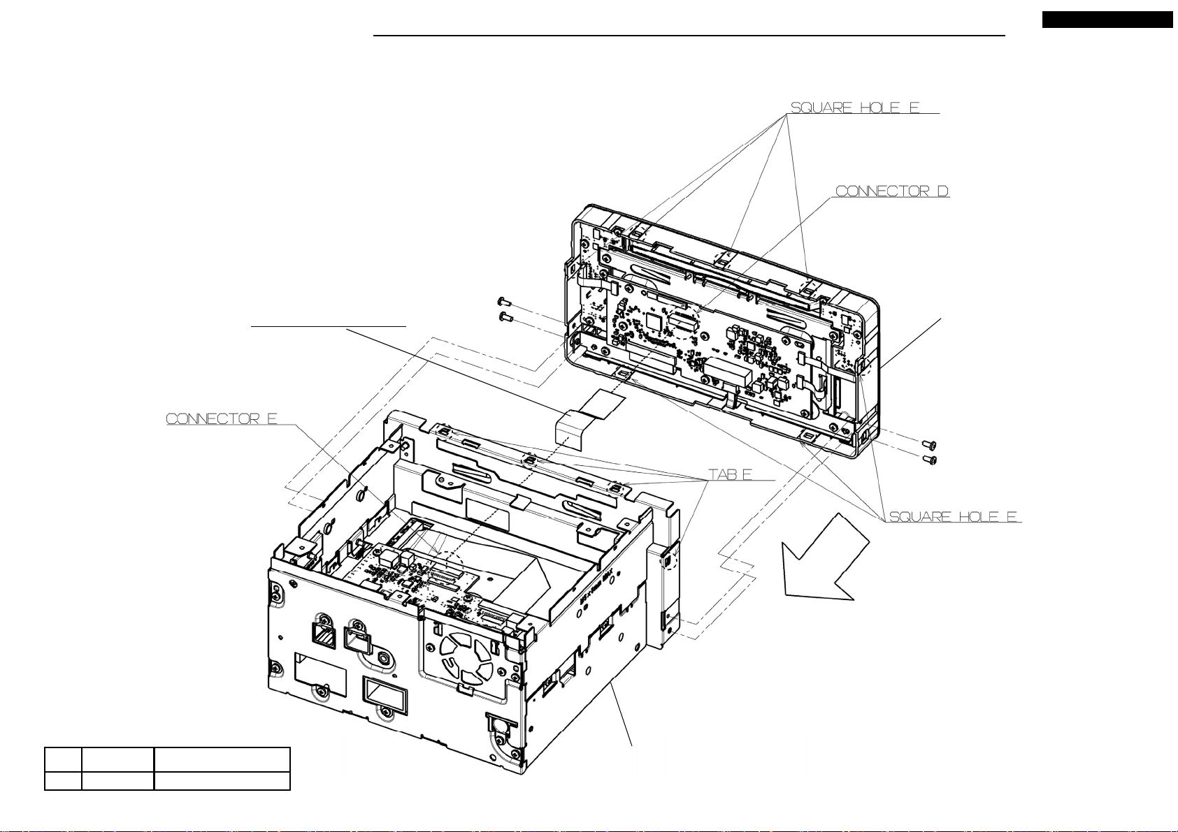
● Assembling procedures
1. Insert M002 to the connector of S2-PANEL. (Connector D)
*Lock connector after inserting M002.
2. Fit tab E of S2-CHASSIS on square hole E of S2-PANEL (7 places),
Screw S2-CHASSIS and S2-PANEL with Ⓐ. (4 places)
3. Insert M002 to the connector of S2-CHASSIS. (Connector E)
*Lock connector after inserting M002.
DY-5MU4R69-T-3,4
M002 : FLAT-CABLE 30P
Ⓐ x 2
S2-PANEL
Ⓐ x 2
No. Screw
Ⓐ
2.6X6 0.5 +0.2/-0.1
Tighten torque(N・m)
S2-CHASSIS
6
Your company internal use only.Copyright (C) Mitsubishi Electric Corporation.

DISASSEMBLING PROCEDURES
● Disassembling procedures
In reverse of assembling procedures.
● Assembling procedures
1. Insert M004 to the connector A and B.
*Lock connector after inserting M004.
DY-5MU4R69-T-3,4
M004 : FLAT-CABLE 60P
S2-CHASSIS
7
S2-CHASSIS
Your company internal use only.Copyright (C) Mitsubishi Electric Corporation.
DISASSEMBLING PROCEDURES
● Disassembling procedures
In reverse of assembling procedures.
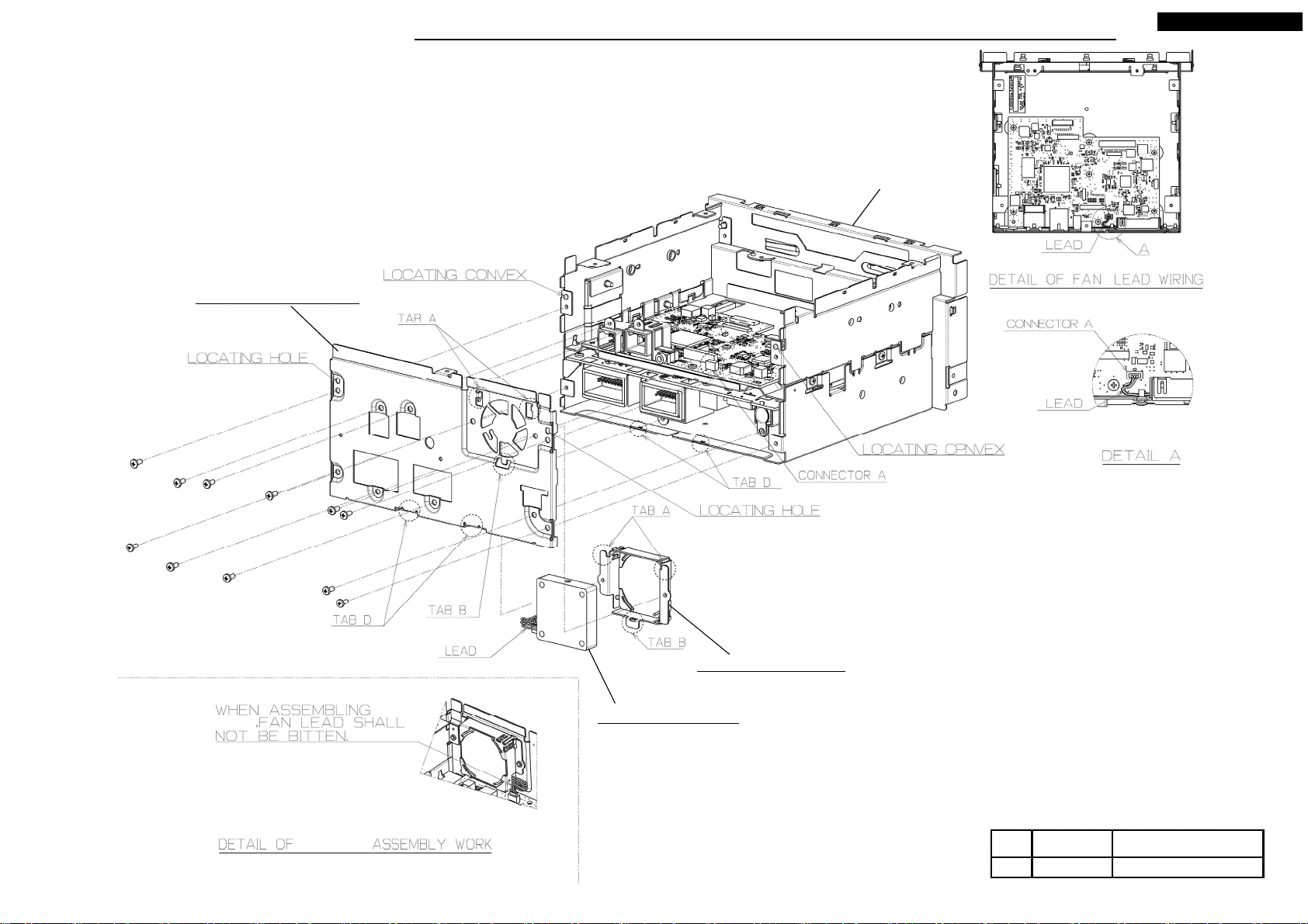
● Assembling procedures
1. After put M005 to M014, tab A and B of M014 fit on tab A and B of M009 and screw with Ⓔ. (2 places)
2. Insert lead to connector A.
3. Fitting tab D after inserting the convex position of S3-CHASSIS
into the locating hole of M009.
4. Screw M009 and S3-CHASSIS with Ⓔ. (9 places)
M009 : CHASSIS-REAR
Ⓔ x 11
DY-5MU4R69-T-3,4
S3-CHASSIS
M009
M014,M005
M014 : HOLDER-FAN
M005 : MOTOR-FAN
8
No. Screw
Ⓔ
2.6X6 0.5 +0.2/-0.1
Your company internal use only.Copyright (C) Mitsubishi Electric Corporation.
Tighten torque(N・m)
DISASSEMBLING PROCEDURES
● Disassembling procedures
In reverse of assembling procedures.
● Assembling procedures
1. After inserting the convex position of S3-CHASSIS into the locating hole of M008,
screw M008 and S3-CHASSIS with Ⓔ. (4 places)
DY-5MU4R69-T-3,4
S3-CHASSIS
Ⓔ x 4
M008 : CHASSIS-F
9
No. Screw
Ⓔ
2.6X6 0.5 +0.2/-0.1
Your company internal use only.Copyright (C) Mitsubishi Electric Corporation.
Tighten torque(N・m)

DISASSEMBLING PROCEDURES
● Disassembling procedures
In reverse of assembling procedures.
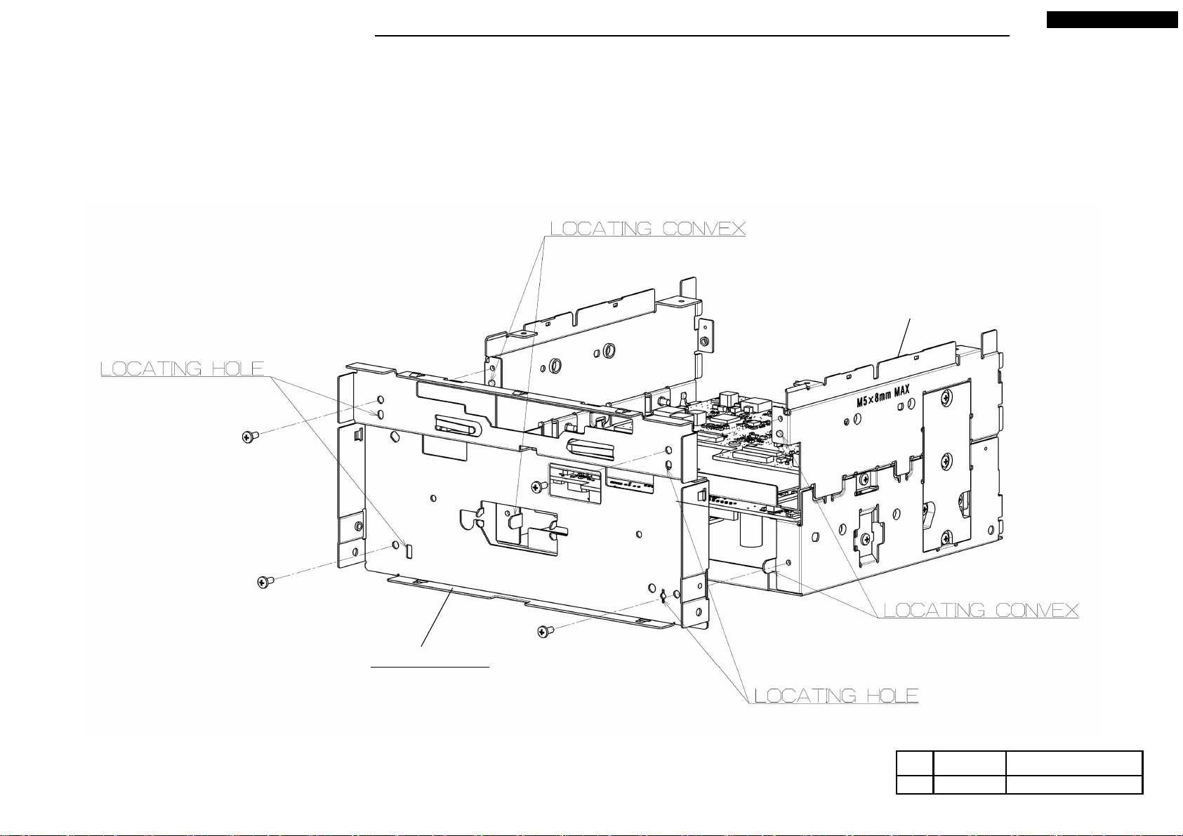
● Assembling procedures
1. Insert the locating convex of S4-CHASSIS into the locating groove of CHASSIS-M. (2 places)
2. Screw CHASSIS-M and S4-CHASSIS with Ⓔ. (3 places)
3. Screw M016 and S4-CHASSIS with Ⓔ (3 places) and Ⓕ. (2 places)
4. Screw S4-CHASSIS and CHASSIS-M with Ⓕ. (1 place)
CHASSIS-M
DY-5MU4R69-T-3,4
No. Screw
Ⓔ
Ⓕ
2.6X6 0.5 +0.2/-0.1
2.6X12 0.5 +0.2/-0.1
Tighten torque(N・m)
S4-CHASSIS
Ⓔ x 4
Ⓕ
Ⓕ
Ⓕ
M016 : HEAT-SINK
10
Ⓔ x 2
Your company internal use only.Copyright (C) Mitsubishi Electric Corporation.

DISASSEMBLING PROCEDURES
● Disassembling procedures
In reverse of assembling procedures.
● Assembling procedures
1. Insert the locating convex of M007 into the locating hole of M027. (2 places)
And fit M027 to M007.
2. Screw M027 with Ⓔ. (7 places)
DY-5MU4R69-T-3,4
Ⓔ x 7
M027 : ASSY-PCB-MEDIA-T
11
M007 : CHASSIS-M
No. Screw
Ⓔ
2.6X6 0.5 +0.2/-0.1
Your company internal use only.Copyright (C) Mitsubishi Electric Corporation.
Tighten torque(N・m)
 Loading...