

Mitsubishi DY-2X64WT-2-TH Service Manual
DY-2X64WT-2-TH
2006 SEP.Your company internal use only
MITSUBISHI MORTORS
SERVICE MANUAL
FM / AM ELECTRONIC TUNING RADIO,
CD PLAYER with CD CHANGER CONTROL
Model : DY-2X64WT-2-TH
PART No : 8701A053
For the mecha part, please refer to the service manual of CD7WMA(211) (2006 JUL.).
CONTENTS
FEATURES/SPECIFICATIONS .................................. 2
OPERATION
DETACHABLE KEY BOARD (DKB) PART ....................... 3
RADIO PART .................................................................... 3
CD, CD CHANGER PART .................................................. 4
AUDIO & OTHERS PART .................................................. 5
REAR VIEW and CONNECTORS .............................. 6
SYSTEM CONFIGURATION ....................................... 7
BLOCK DIAGRAM ...................................................... 8
DISASSEMBLING PROCEDURES ...................... 9~11
EXPLODED VIEW and PARTS LIST ........................ 12
IC EXPLANATION ............................................... 13~16
ELECTRICAL PARTS LIST ................................. 17,18
PARTS LAYOUT ON PRINTED CIRCUIT BOARD
PCB-MAIN................................................................. 19,20
PCB-PANEL .................................................................... 21
SCHEMATIC DIAGRAM
PCB-MAIN................................................................ 22~26
PCB-PANEL .................................................................... 27
VOLTAGE ................................................................. 28
WAVEFORM ............................................................. 29
SE011306093E
MITSUBISHI ELECTRIC CORP. SANDA WORKS
Copyright (c) Mitsubishi Electric Corporation

FEATURES / SPECIFICATIONS
FEATURES
SPECIFICATIONS
Audio Amp
Including high power 4CH Amp.
Adjustment of BASS,TREBLE, FADER and BALANCE by the
audio adjustment button.
Sound preset function. (Sound adjustment state can preset
the 6 sorts.)
Auto loudness function varies a frequency characteristic by
volume.
The function that controls the amount of change in the low /
high frequency tone (BASS / TREBLE) adjustment with the
maximum volume.
ATC (Auto Tone Control) function that controls the low / high
frequency tone (BASS / TREBLE) by radio-field strength at
the receipt of AM.
Radio
FM and AM can preset the 6 stations.
Improvement in the tuning operationality by the Auto store
function.
TUNE button is a double function button operating of auto-
matic tuning and manual tuning.
CD Player
Power Loading / Power Eject function.
Skip recovered function.
(Recovered the condition before skip.)
Protected function of laser pick-up stopping at high tempera-
ture.
Quick track selection function.
Fast-forward / fast-rewind replay function.
Repeat function. (One tune)
Scan function : 10 sec
Available for loading both 8cm and 12cm disc.
Random play function.
Any time Eject function. (Eject at the all mode included ACC
OFF.)
CD-MP3 reproduction function.
(CD-DA/MP3 coexistence disc, TITLE/ID3tag display, MPEG1 AUDIO Layer3, MPEG-2 AUDIO Layer3)
Others
FM Radio
Frequency Range : 87.5 ~ 108.0MHz
(SEEK:50kHz / STEP:25kHz)
Intermediate Frequency : 10.7MHz
Sensitivity (-3dB Limiting) : Less than 14dB(µV)
AM Radio
Frequency Range : 531 ~ 1629kHz
(SEEK:9kHz,1kHz / STEP:1kHz)
Intermediate Frequency : 450kHz
Sensitivity (20dB S/N) : Less than 32dB(µV)
CD Player
Laser : Semiconductor Laser
DA Convertor : 16bit
Dynamic Range : More than 65dB
Signal/Noise Ratio : More than 65dB
Channel Separation : More than 40dB
Others
Power Supply : DC 12V (11~16V)
Test Voltage 13.2V
Negative ground
Battery Back Up Current : Less than1.0mA
Current Consumption : ACC 2.4A ± 20%
(Output 1W)
: ACC 10A ± 20%
(MAX.Output)
Maximum Power Output : 25W x 4
Output Impedance : 4
Dimensions : 178(W) x 169(D) x 50(H)mm
Weight : 1.3kg
CD auto changer / in-dash CD changer operating function.
M-BUS is used the method of communication with CD auto
changer, in dash CD changer, MD player and LCD monitor.
The connection of speaker wiring can check by test mode of
the beep in the vehicle's assembly line.
Each mode is display on the connected LCD monitor (audio
display).
Control of panel buttons illumination and the connected
LCD illumination brightness by rheostat.
Telephone mute function.
Telephone voice interrupt function.
Stereo AUX input terminal equipnment.
Even during BATT OFF, the channel preset memory is retained (usage of EEPROM).
The beep sounds, to check an operation, by using a button
with hold-pushing operation function (using the buzzer on the
vehicle side).
Theft prevention security function by PANEL OUT. (Blink
alarm-flash LED at ACC OFF.)
Put out lights of the lamp by PANEL OUT at ILL ON.
2

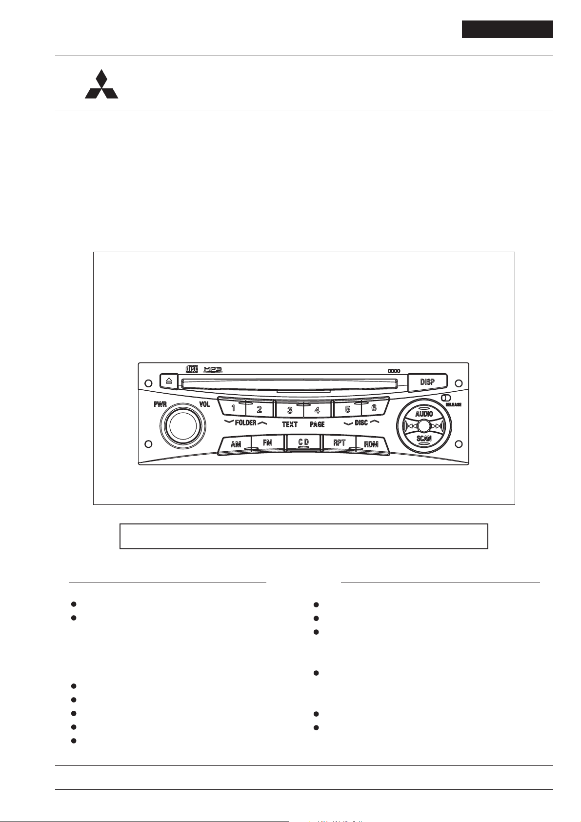
OPERATION
DETACHABLE KEY BOARD (DKB) PART
ALARM FLASH
RELEASE Switch
PARTIAL PANEL OUT
Detachable Key Board (DKB)
To effectively prevent theft of the car stereo, the Control Key
Board can be removed rendering the set absolute use-
less.
How to remove the Key Board:
Slide the RELEASE switch rightward, and take the Key
Board out of panel when it comes lose. (When the Key
Board is removed, the power is turned off.)
How to reinstall the Key Board:
Side it in its original position and push it in slightly until it is
locked. (At that time, the power is automatically switched
on.)
RADIO PART
Memory and Preset Channel Button
Memory : Push the button 1.5 seconds or more.
Preset : Push the button less than 1.5 seconds.
Always keep the surface of electric contacts of the Key
Board clean to prevent malfunctions due to the dust or rust.
Alarmed Flash
When switching off the ignition key, the set flashes the red
ALARMED light to indicate the set under armed condition
against the theft.
Tuning Up/Down Button
Step : Push the button less than 0.5 seconds.
Seek : Push the button 0.5 seconds or more.
Power ON/OFF (Push)
Volume Control(Endless)
RADIO ON Button (FM)
RADIO ON Button (AM)
3
SCAN Button
Automatic tuning in improvement button.
(Reception for the 10 seconds)
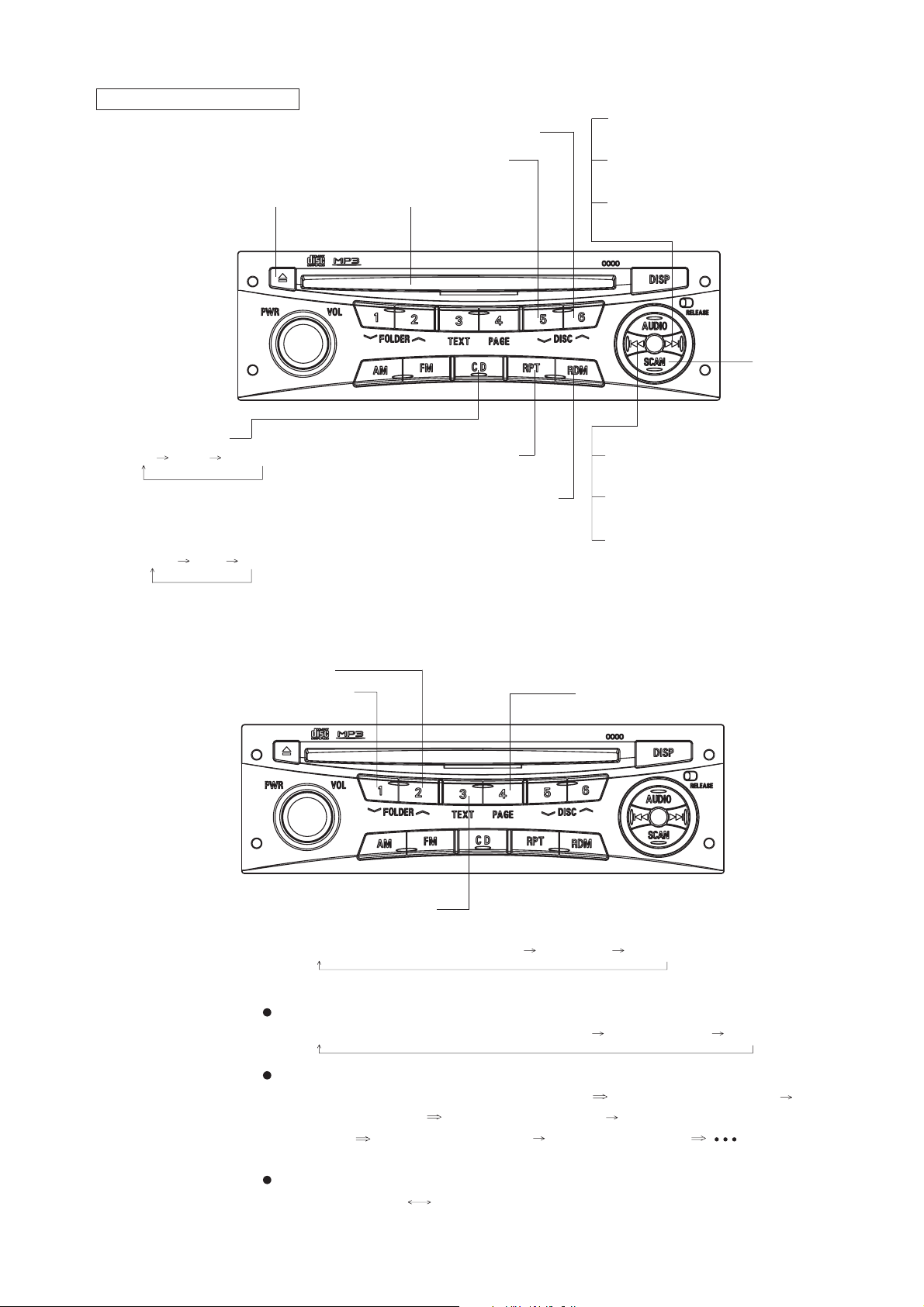
CD, CD CHANGER PART
CD Changer Disc Selection Up Button
CD Changer Disc Selection Down Button
EJECT Button CD SLOT
CD Mode Button
CD CD-X CD Changer
<Coexistence Disc Operation Transition>
(Push the button less than 1.5 seconds,
and the operation sound is generated.)
CD-DA MP3 AUX
Track Selection Up Button
(Push the button less than 0.5 seconds)
Fast-forward Button
(Push the button 0.5 seconds or more)
Track(File) Selection Up Button (MP3)
(Push the button 0.5 seconds or more)
CD Scan Button
Repeat Play Button Track Selection Down Button
(Push the button less than 0.5 seconds)
Random Play Button
Fast-rewind Button
(Push the button 0.5 seconds or more)
Track(File) Selection Down Button(MP3)
(Push the button less than 0.5 seconds)
FOLDER Selection Up Button(MP3)
FOLDER Selection Down Button(MP3)
TEXT Selection Button(MP3)
<For CD-TEXT>
Display usually(Track and elapsed time) Disc Name Track Name
<For MP3>
[Title display usually]
Display usually(FOLDER, Track and elapsed time) FOLDER Name File Name
[ID3-TAG Title display]
Display usually(FOLDER, Track and elapsed time) Album(assistance display) (in
two seconds)Album Title Track(assistance display) (in two seconds)FileName-
Folder Name Artist(assistance display) (in two seconds)Artist
PAGE Sender Button(MP3)
The display mode is changed by the pushing the botton long press.
[Title display usually] [ID3-TAG Title display]
4

AUDIO & OTHERS PART
AUDIO Control Memory and Preset Channel Button
Memory : Push the button 1.5 seconds or more.
Preset : Push the button less than 1.5 seconds.
AUDIO Control
Mode Selection Button
BASS TREBLE FADER BALANCE
Cancel
ID code
DISPLAY Button
AUDIO Control Down Button
Power ON/OFF
(Push)
Function Setting OFF Button
Volume Control (Endless)
1) Level Control BASS/TREBLE/FADER/BALANCE
Push the AUDIO Button to select function among BASS/
TREBLE/FADER/BALANCE.
At the each AUDIO mode, push AUDIO Control Up/Down
Button to change its level according to the indication as the
right or below display.
After 7 seconds, the previous screen will be automatically
resumed.
AUDIO Control Up Button
Function Setting ON Button
SCAN Button
When the scan operation reaches the first track of
which first 10 seconds was played, it is automati-
cally and normal playback starts.
AUDIO Control
Button
BASS
TREBLE
Down
Up
_
_
+
+
FADER R F
BALANCE L R
5
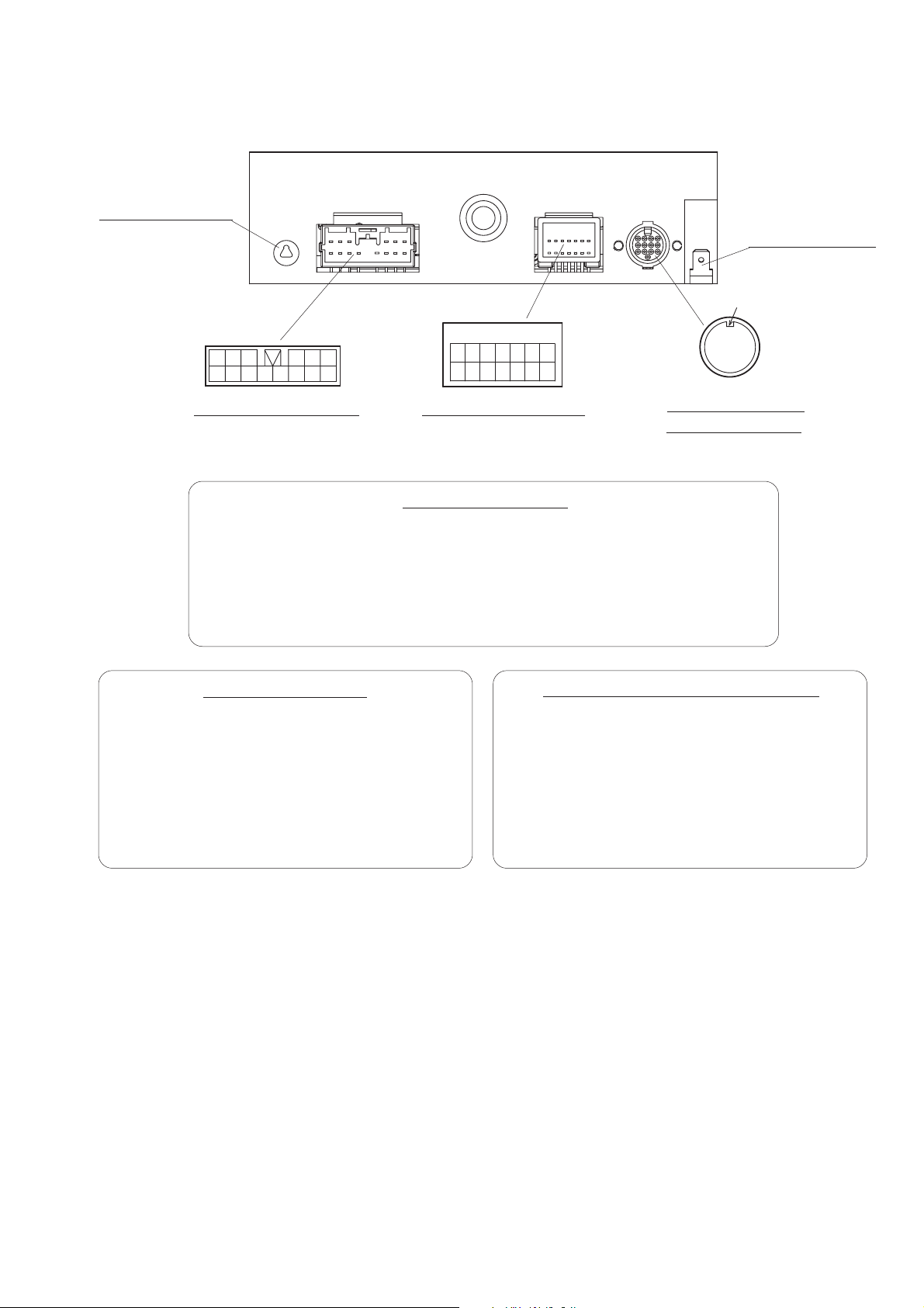
REAR VIEW and CONNECTORS
ANTENNA SOCKET
6
14 13 12 1110 9 8
14P CONNECTOR (P901)
12345
7
14P CONNECTOR (P901)
1234567
891011121314
14P CONNECTOR (J802)
TERMINAL EARTH
H
43 21
87 6 5
12 11 10 9
13
DIN 13P CD Changer
CONNECTOR (J801)
1: M-BUSY
2: M-DATA
3: REMO SIG 1
_
4:
5: TEL MUTE 1
6: TEL SIG 1
7: TEL GND 1
1: Speaker FR ( + )
2: Speaker FL ( + )
3: Illumination ( + )
4: Antenna +B
5: Speaker RL ( + )
14P CONNECTOR (J802)
8: M-SCK
9: Shield Earth
10: REMO SIG 2
_
11:
12: Aux L
13: Aux R
14: Aux GND
6: Speaker RR ( + )
7: Speaker FR (
_
8: Speaker FL ( _ )
9: Illumination ( _ )
10: Battery ( + )
DIN 13P CD Changer CONNECTOR (J801)
1: Signal GND
2: BUS L
_
3:
4: BUS R
_
5:
_
6:
7: Accessory ( + )
11: Accessory ( + )
12:
_
)
13: Speaker RL (
14: Speaker RR (
_
)
_
)
_
8:
9: Battery ( + )
10: Illumination ( + )
11: M-BUSY
12: M-SCK
13: M-DATA
H: Shield Earth
6

SYSTEM CONFIGURATION
Audio
DY-2X64WT-2-TH
Battery
Shield Earth
Accessory
M-SCLK
M-BUSY
M-DATA
Shield Earth
RV Meter
(DU-467-1)
Illumination(+)
Illumination(_)
CD Changer
(CD-5000C)
7

BLOCK DIAGRAM
PCB-MAIN
IC303
NJM4565V
BUFFER AMP
IC304
NJM4565V
BUFFER AMP
RV meter
Buffer
M-Bus
J802
Connector
XTAL
M-Bus
P801
Connector
X801
8MHz
IC803
RESET
Panel Key
PCB-PANEL
IC305
ANALOG SW
PST-3464
CD4066BPWR
3.3V Power
Supply circuit
IC981
J801
Connector
S-818A33AUC-BGN
5V Power
Supply Circuit
XTAL
X201
4.332MHz
Antenna
IC802
EEPROM
IC201
RDS Decoder
FE1
TUNER
184E-3AF
BR93LC56FV
IC801
BU1924F
(F.E.+FM-IF)
IC101
MAIN µ-COM
µPD780076GK-699-9ET
PLL-IC
LC72151VS
XTAL
X101
10.35MHz
IC805
LEVEL SHIFTER
SN74AHCT244
IC804
LEVEL SHIFTER
SN74AHC2G34HDCTR
CCB-Bus
CD-7
Mecha
BUFFER
IC302
NJM4565V
ELE-VOL
LC75411UES
IC301
8V Power
Supply Circuit
Circuit
Low-Boost
IC3A1
9V Power
Supply Circuit
P901
Connector
12V
Output
LA4742
Power-IC
8

DISASSEMBLING PROCEDURES
1. Removal of PLATE-SPR and COVER (See Fig.1)
1) Unscrew the two screws ( ).
2) Remove the two PLATE-SPR.
3) Unscrew the four screws ( ).
4) Remove the COVER.
1
2
PLATE-SPR
1
(J)
COVER
2
4 (M)
2. Removal of CD7 (See Fig.2)
1) Unscrew the four screws ( ).
2) Remove the FLAT-CABLE 18P.
3) Remove the CD7.
3
CD7
PLATE-SPR
1
(J)
(Fig.1)
3
4 (L)
FLAT-CABLE 18P
(Fig.2)
9
 Loading...