

Page 1
SE050613063E Ver.pptx14E
CONTENTS
● FEATURES .............................. ...........................................2
● SPECIFICATIONS ..............................................................3
● OPERATION ............................ ...........................................4
● CONNECTORS ..................................................................5
● SYSTEM CONFIGURATION ..............................................6
● BLOCK DIAGRAM ..............................................................7
● DISASSEMBLING PROCEDURES ............................. 8~13
● PARTS LIST ...................................................................... 14
● ELECTRICAL PARTS LIST ........................................ 15~21
● PARTS LAYOUT ON PRINTED CIRCUIT BOARD .... 22~25
● SCHEMATIC DIAGRAM
● VOLTAGE ......................................................................... 29
● WAVEFORM .............................................................. 30~32
DY-1MU3E21-T
2014 May.
MITSUBISHI MOTORS
SERVICE MANUAL
USB, AM / FM-ST ELECTRONIC TUNING RADIO,
CD PLAYER
PCB-MAIN .............................................................. 26,27
PCB-PANEL ................................. ................................ 28
Model : DY-1MU3E21-T
MELCO Code : 34W824
PART No. : 8701A368
MITSUBISHI ELECTRIC CORP. SANDA WORKS
Your company internal use only.Copyright (C) Mitsubishi Electric Corporation.
Page 2

FEATURES
DY-1MU3E21-T
< Audio Part >
● Built-in high-power 4-ch amplifier. (Supporting 4Ω load)
● Bass, Treble, Fader and Balance control with audio control buttons.
● Volume level control with up/down button.
(BASS, TREBLE : ±6step / FADER, BALANCE : ±11step)
● Auto loudness to change frequency characteristics in response to volume levels.
● Controlling tone control amount of BASS / TREBLE at maximum volume level.
< Radio Part >
● Memory/call operation with preset memory buttons.
(FM1, FM2, AM : A maximum of 6 stations respectively)
< CD Part >
● Powered loading and ejecting function.
● Dropout recovery function to return to previous playback point upon dropout or error.
● Laser pickup high-temperature protecting function to terminate playback when
ambient temperature rises.
● Track selecting function to enable instant random access to songs.
● Any Time Eject.
(Allowing disk eject (powered eject) in all modes including ACC OFF.)
● RELOAD function. (Avoid keeping disk ejection status.)
● Title display function.
● Supporting 12-cm CD only. (Not supporting 8-cm CD)
● Supporting mp3. (MPEG1 AUDIO LAYER3, MPEG2 AUDIO LAYER3)
[CD-DA]
● Repeat play. (One-song repeat function and disk repeat function)
● Random play function. (Random play in disk)
● Fast forward/Rewind function.
[MP3]
● Repeat play function. (One-song repeat in folder)
● Random play function. (Random play in folder, random play in all folders of disk)
● Fast forward/Rewind function.
< USB Part >
1) Playback of compressed and non-compressed audio files in USB mass storage.
● USB2.0 Full-speed compatible.
● MP3/WMA/AAC playback.
● File information acquisition.
● Bus power supported.
2) iPod control/playback by USB connection.
● USB2.0 Full-speed compatible.
● Supporting iPod control.
● Playback of audio files in iPod.
● Supporting iPod charger by bus power.
Compatible USB device
USB device
Compatible X X
The following table shows an example of compatible USB devices:
Compatible = O : Playable (recommended)
Compatible = : Playable (not recommended)
Compatible = X : Not playable
(*1) : Compatible with 256MByte or larger memory.
Compatible with 128MByte memory in FAT16 format only.
Not compatible with HUB class memory.
(*2) : Compatible with mass-storage class supporting digital audio player (DAP).
Sub class: SCSI, Protocol: Not compatible except for Bulk-Only.
Not compatible with devices supporting MTP only.
(*3) : May not be playable depending on driving voltage or power consumption of device.
(*4) : May not be playable depending on specifications of card reader or memory card.
Flash
Memory
O
(*1)
△
DAP HDD
O
(*2) (*3) (*4)
△△
Card
reader
CD/DV D
/FDD
HUB iPod
O
< Others >
● Clock function 12-hour indication.
● Generates operating tone for confirmation using hold-down button.
● Setting test mode for speaker wiring connection diagnosis (oscillating tone output)
and distortion tone check in vehicle assembly lines.
● Stereo AUX input front terminal provided.
● Power shutoff operation by holding down center encoder key.
● BT-HFM connection function.
2
Your company internal use only.Copyright (C) Mitsubishi Electric Corporation.
Page 3

SPECIFICATIONS
DY-1MU3E21-T
< AM Radio >
● Frequency Range : 530~1710kHz (10kHz step)
● Practical Sensitivity : Less than 34dBμV
● Signal/Noise Ratio : More than 45dB
(60dBμV)
< FM Stereo Radio >
● Frequency Range : 87.75~107.9MHz (200kHz step)
● Limiting Sensitivity : Less than 10dBμV
● Signal/Noise Ratio : More than 55dB
(40dBμV)
< CD Player >
● Dynamic Range : More than 65dB
● Signal/Noise Ratio : More than 65dB
● Channel Separation : More than 55dB (1kHz)
< USB Interface >
● Dynamic Range : More than 65dB
● Signal/Noise Ratio : More than 65dB
● Channel Separation : More than 55dB (1kHz)
< Others >
● Power Supply : DC 13.2V (10~16V)
Test Voltage 13.2V
Negative ground
● Backup Current : Less than 1.6mA
● Current Consumption : typ. 2.5A
(CD1kHz 0dB Output 1W : Ta=25℃
The apparatus of USB is not connected.)
● Maximum Power Output : 35W x 4
● Output Impedance : 4Ω (SP Output)
● Working Temperature Range
CD : -20℃ ~ +70℃
RADIO, Other modes : -30℃ ~ +70℃
● Storage Temperature Range : -40℃ ~ +80℃
● Dimensions (W x D x H) : 293.0mm x 121.9mm x 188.9mm
● Weight : 1.65kg
3
Your company internal use only.Copyright (C) Mitsubishi Electric Corporation.
Page 4

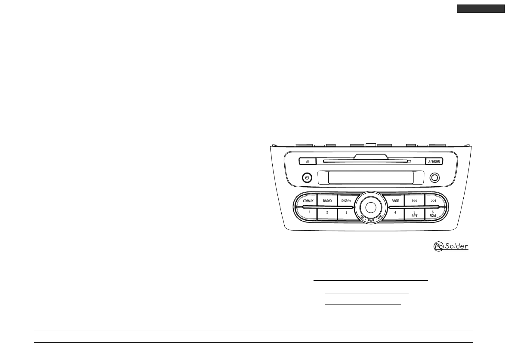
OPERATION
DY-1MU3E21-T
AUX 4P Jack
4
Your company internal use only.Copyright (C) Mitsubishi Electric Corporation.
Page 5
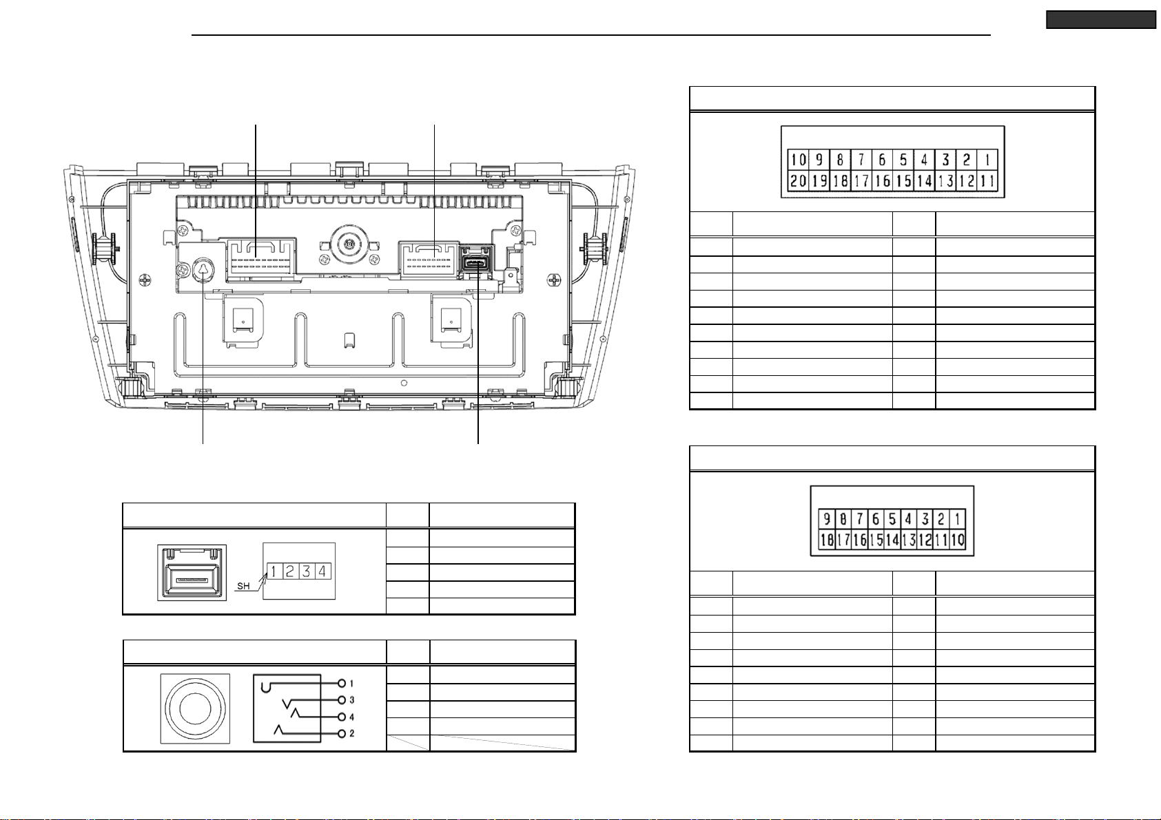
CONNECTORS
Power supply,
Speaker and Remote controller
20P Connector
IE-BUS and HFM
18P Connector
Power supply, Speaker and Remote controller 20P Connector
PinNo. Signal Name PinNo. Signal Name
1 BATTERY (+) 11 POWER GND
2 ILLUMINATION (+) 12 ILLUMINATION (-)
3 SPEAKER FL (+)
4 SPEAKER RL (+) 14 SPEAKER RL (-)
5 SPEAKER FR (+)
6 SPEAKER RR (+) 16 SPEAKER RR (-)
7 8 - 18 9 REMOCON
10 ACCESSORY (+) 20 VEHICLE SPEED PULSE
SPEAKER FL (-)
13
SPEAKER FR (-)
15
ANTENN A + B
17
REMOCON GND
19
DY-1MU3E21-T
Antenna Socket USB device
4P Connector
USB device 4P Connector PinNo. Signal Name
1 USB VBUS
2 USB DATA 3 USB DATA +
4 USB GND
SH USB SH
AUX 4P Jack (Panel side) PinNo. Signal Name
1 2 AU X-GN D
3 AU X-R
4 AU X-L
5
IE-BUS and HFM 18P Connector
PinNo. Signal Name PinNo. Signal Name
1 IE-BUS(+) 10 IE-BUS (-)
2 IE-BUS POWER ON 11 IE-BU S SHIELD GN D
3 4 - 13 5 6 HFM S-INPUT LEFT 15 7 HFM S-INPUT RIGHT
8 - 17 HFM SHIELD GND
9 - 18 -
-
12
-
14
HFM S-INPUT GND
16
Your company internal use only.Copyright (C) Mitsubishi Electric Corporation.
Page 6
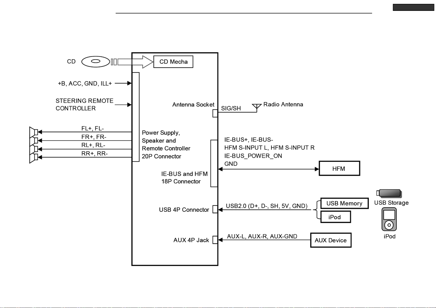
SYSTEM CONFIGURATION
DY-1MU3E21-T
6
Your company internal use only.Copyright (C) Mitsubishi Electric Corporation.
Page 7

BLOCK DIAGRAM
DY-1MU3E21-T
7
Your company internal use only.Copyright (C) Mitsubishi Electric Corporation.
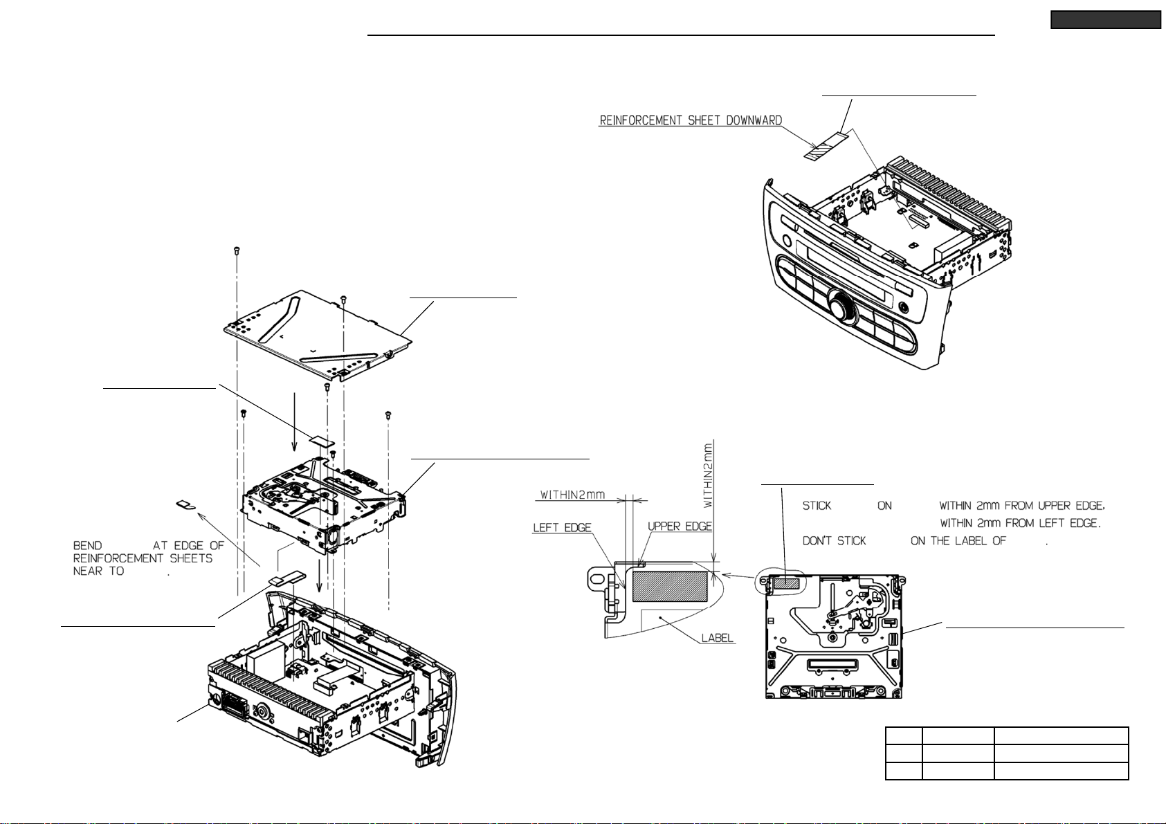
Page 8

DISASSEMBLING PROCEDURES
*It is assembling procedure. Disassembling procedure is in reverse.
DY-1MU3E21-T
M015 : NAME-CARD(DY-1MU3E21-T)
8
Your company internal use only.Copyright (C) Mitsubishi Electric Corporation.
Page 9
DISASSEMBLING PROCEDURES
● Disassembling procedures
In reverse of assembling procedures.
● Assembling procedures
1. Lock connector after inserting M001 to the connector of S2-DY as figure below.
Then insert reverse side to M001 and lock the connector.
2. Screw M014 and S2-DY with Ⓒ. (4 places)
3. Stick M009 on M014. (Follow lower right figure)
4. Insert 2 tabs of M005 to the rectangle hole of S2-DY,
and fit tabs on the 2 sides of M005, the screw M005 with Ⓐ.
DY-1MU3E21-T
M001 : FLAT-CABLE 18P
M009 : SHEET-HS
M014
M014
M001 : FLAT-CABLE 18P
Ⓐ x 2
M005 : COVER-U
Ⓒ x 4
M014 : CD8-MECHA(955823)
M009 : SHEET-HS
M009 M014
M009 M014
M014 : CD8-MECHA(955823)
S2-DY
9
No. Screw
Ⓐ
Ⓒ
3X6 0.8 +0.2/-0.1
2.6X6S 0.6 +0.2/-0.1
Your company internal use only.Copyright (C) Mitsubishi Electric Corporation.
Tighten torque(N・m)
Page 10
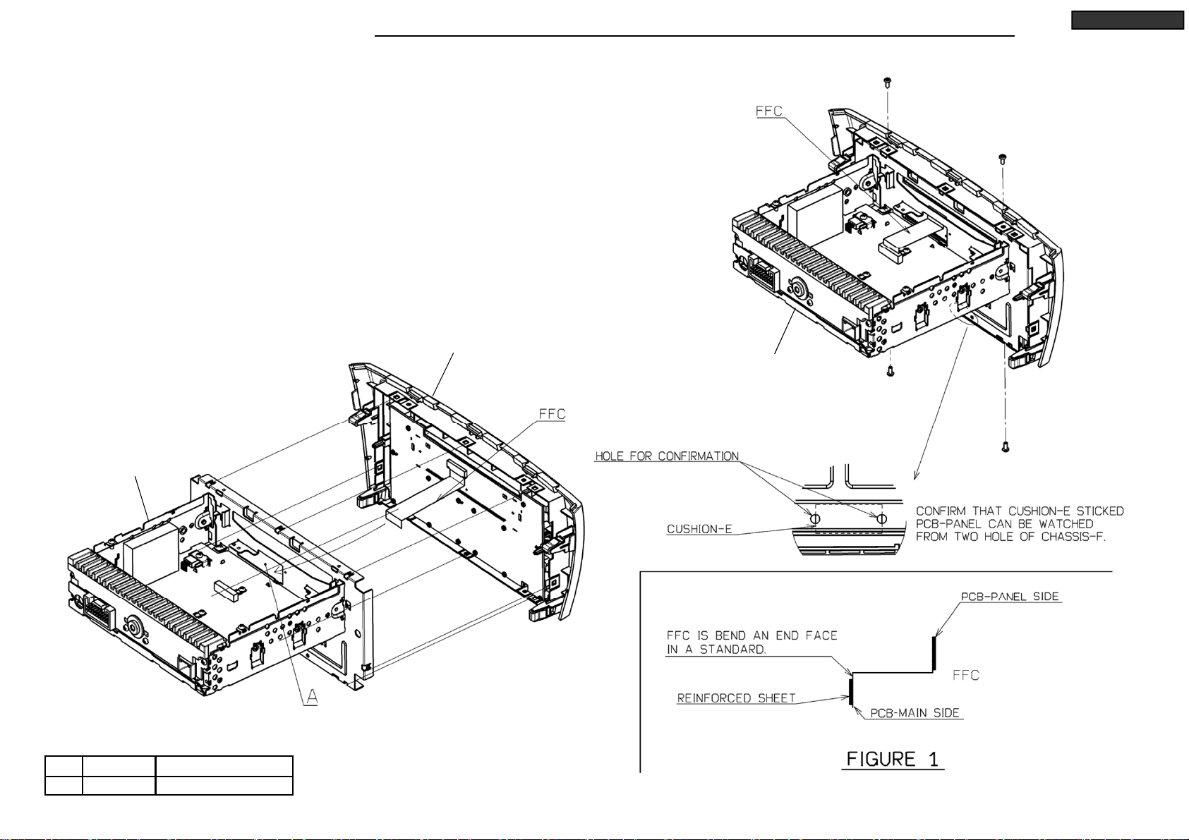
DISASSEMBLING PROCEDURES
● Disassembling procedures
In reverse of assembling procedures.
● Assembling procedures
1. Fit tab of S2-DY on S2-PANEL. (8 places)
*Then, put FFC through A.
2. Lock FFC after screw S2-DY and S2-PANEL with Ⓒ. (4 places)
*FFC locked after bend standard of reinforcement sheet.
(Follow FIGURE 1)
DY-1MU3E21-T
Ⓒ x 2
S2-PANEL
S2-DY
S2-DY
No. Screw
Ⓒ
2.6X6S 0.6 +0.2/-0.1
Tighten torque(N・m)
10
Ⓒ x 2
Your company internal use only.Copyright (C) Mitsubishi Electric Corporation.
Page 11

DISASSEMBLING PROCEDURES
● Disassembling procedures
In reverse of assembling procedures.
● Assembling procedures
1. Fit tabs on 2 sides of M003 on ASSY-CHASSIS-B and
screw ASSY-CHASSIS-B and M003 with Ⓐ.
*After contact the end face of the C on ASSY-CHASSIS-B in end face of B on M003
as fit B and C, D and E, F and G, slide M003 direction of the ground.
(Follow the right figure)
2. Stick M007 for M003. (Follow the detail)
DY-1MU3E21-T
Ⓐ x 2
M007 : CUSHION-E
No. Screw
Ⓐ
3X6 0.8 +0.2/-0.1
Tighten torque(N・m)
M003 : CHASSIS-F
ASSY-CHASSIS-B
11
M003 : CHASSIS-F
M007 : CUSHION-E
M007
M003
M003 M007
M007
Your company internal use only.Copyright (C) Mitsubishi Electric Corporation.
Page 12

DISASSEMBLING PROCEDURES
● Disassembling procedures
In reverse of assembling procedures.
● Assembling procedures
1. Stick M008 and M010 on M013. (Follow the right figure)
2. Put PCB-MAIN to M013 and screw with Ⓐ (4 places), Ⓓ (4 places).
(Check that 4 tabs of M013 are into holes of PCB-MAIN.)
Stick M007 to PCB-MAIN. (Follow the right figure)
3. Screw M004 to M013 with Ⓐ (2 places).
4. Screw M006 to M013 with Ⓐ (3 places), Ⓑ (2 places).
M010 : SHEET-HS
M010
M013 : ASSY-CHASSIS-B
DY-1MU3E21-T
M007
M007
No. Screw
Ⓐ
Ⓑ
Ⓓ
Ⓓ x 2
3X6 0.8 +0.2/-0.1
3X16
2.6X10S 0.6 +0.2/-0.1
PCB-MAIN
Tighten torque(N・m)
0.65 ±0.1
Ⓐ x 4
Ⓓ
M004 : BRACKET-DECK
Ⓐ x 2
Ⓓ
M007 : CUSHION-E
Ⓐ x 2
Ⓑ x 2
M008 : SHEET-HS
M008
PCB-MAIN
PCB-MAIN M013
M013
M007 :
CUSHION-E
PCB-MAIN
M010 : SHEET-HS
Ⓐ
M008 : SHEET-HS
M013 : ASSY-CHASSIS-B
M006 : HEAT-SINK
12
M013 : ASSY-CHASSIS-B
Your company internal use only.Copyright (C) Mitsubishi Electric Corporation.
Page 13

DISASSEMBLING PROCEDURES
● Disassembling procedures
In reverse of assembling procedures.
● Assembling procedures
1. Stick M016 on M012. (Follow the detail.)
2. Remove the protection sheet,
and screw PCB-PANEL and M012 with Ⓔ.
3. Fit M011 to PCB-PANEL.
4. Lock connector after inserting M002 to PCB-PANEL.
(Follow the detail.)
M002 : FLAT-CABLE 18P
DY-1MU3E21-T
M016
M011 : KNOB-VOL
Ⓔ x 14
No. Screw
Ⓔ
2X6 0.2 +0.15/-0.04
Tighten torque(N・m)
PCB-PANEL
13
M012 : ASSY-PANEL
M016 : SHEET-LCD
M002
M002
Your company internal use only.Copyright (C) Mitsubishi Electric Corporation.
Page 14

PARTS LIST
Ref. No. Parts No. Parts Nam e Page
M001 246L58085 FLAT-CABLE 18P P.9
M002 246L58086 FLAT-CABLE 18P P.13
M003 560J42611 CHASSIS-F P.11
M004 591K40713 BRACKET-DECK P.12
M005 591K81321 COVER-U P.9
M006 635J12722 HEAT-SINK P.12
M007 643L84416 CUSHION-E P.11,12
M008 643L89720 SHEET-HS P.12
M009 643L89730 SHEET-HS P.9
M010 643L91912 SHEET-HS P.12
M011 734L99820 KNOB-VOL P.13
M012 892K54358 ASSY-PANEL P.13
M013 893K29611 ASSY-CHASSIS-B P.12
*M014 940L24414 CD8-MECHA(955823) P.9
M015 959M012O7 NAME-CARD(DY-1MU3E21-T) P.8
M016 644L18510 SHEET-LCD P.13
A 653P11046 SCREW-S-PAN 3X6 B 653P11052 SCREW-S-PAN 3X16 C 653P13028 SCREW-S-BIND 2.6X6S D 653P13032 SCREW-S-BIND 2.6X10S E 653P33014 SCREW-P-BIND 2X6 -
DY-1MU3E21-T
* Marked part is the ASSY replacement.
14
Your company internal use only.Copyright (C) Mitsubishi Electric Corporation.
Page 15

A
ELECTRICAL PARTS LIST
Ref. No. Parts No. Parts Name Note Spec.
NT1 449L076O2 SOCKET-ANT N931L91813 C359 141L066O8 C-CERAMIC-CHIP GRM21BB11E224KA01L B 25V 224K 2125 N931L91713
C101 141L181O5 C-CERAMIC-CHIP GRM1882C1H150JA01D CH50V150J 1608 N931L91713 C360E 181P80123 C-ELECTROLYTIC-CHIP UWX1C100MCL1GB 16V 100M N931L91713
C102 141L069O1 C-CERAMIC-CHIP CM21B225K10AT-N B 10V 225K 2125 N931L91713 C361E 181P80123 C-ELECTROLYTIC-CHIP UWX1C100MCL1GB 16V 100M N931L91713
C103 141L069O1 C-CERAMIC-CHIP CM21B225K10AT-N B 10V 225K 2125 N931L91713 C371 141L187O1 C-CERAMIC-CHIP GRM1882C1H561JA01D CH 50V 561J1608 N931L91713
C104 103L299O9 R-CHIP RMC1/16JTP 1/10W 0 1608 N931L91713 C372 141L187O1 C-CERAMIC-CHIP GRM1882C1H561JA01D CH 50V 561J1608 N931L91713
C105 103L299O9 R-CHIP RMC1/16JTP 1/10W 0 1608 N931L91713 C380E 181P80123 C-ELECTROLYTIC-CHIP UWX1C100MCL1GB 16V 100M N931L91713
C106 103L299O9 R-CHIP RMC1/16JTP 1/10W 0 1608 N931L91713 C381 181P80123 C-ELECTROLYTIC-CHIP UWX1C100MCL1GB 16V 100M N931L91713
C111 141P164O9 C-CERAMIC-CHIP GRM1552C1H391JA01D CH 50V 391J1005 N931L91713 C381E 181P80123 C-ELECTROLYTIC-CHIP UWX1C100MCL1GB 16V 100M N931L91713
C112 141P164O9 C-CERAMIC-CHIP GRM1552C1H391JA01D CH 50V 391J1005 N931L91713 C390 181P80124 C-ELECTROLYTIC-CHIP UWR1C220MCL1GB 16V 220M N931L91713
C121 141P150O1 C-CERAMIC-CHIP UMK105BJ221KV-F B 50V 221K1005 N931L91713 C391 141L066O8 C-CERAMIC-CHIP GRM21BB11E224KA01L B 25V 224K 2125 N931L91713
C122 141P153O1 C-CERAMIC-CHIP GRM155B11E103KA01D B 25V 103K1005 N931L91713 C392 181P80161 C-ELECTROLYTIC-CHIP UWX1H010MCL1GB 50V 010M N931L91713
C123 141P158O8 C-CERAMIC-CHIP CM05B473K10AH B 10V 473K1005 N931L91713 C3C1 141L069O1 C-CERAMIC-CHIP CM21B225K10AT-N B 10V 225K 2125 N931L91713
C124 141P158O8 C-CERAMIC-CHIP CM05B473K10AH B 10V 473K1005 N931L91713 C3C3 141P163O5 C-CERAMIC-CHIP GRM1552C1H101JA01D CH 50V 101J1005 N931L91713
C125 141P158O8 C-CERAMIC-CHIP CM05B473K10AH B 10V 473K1005 N931L91713 C401 141L165O0 C-CERAMIC-CHIP GRM188B10J105KC01D B6.3V 105K 1608 N931L91713
C141 141L164O9 C-CERAMIC-CHIP CM105W5R474K10AT B 10V 474K 1608 N931L91713 C402 141L163O4 C-CERAMIC-CHIP GRM188B11E273KA01D B 25V 273K 1608 N931L91713
C142 141L164O9 C-CERAMIC-CHIP CM105W5R474K10AT B 10V 474K 1608 N931L91713 C408 141P159O2 C-CERAMIC-CHIP C1005JB1A224KT B 10V 224K 1005 N931L91713
C145 141L164O9 C-CERAMIC-CHIP CM105W5R474K10AT B 10V 474K 1608 N931L91713 C409 181P80127 C-ELECTROLYTIC-CHIP UWX1C101MCL1GB 16V 101M N931L91713
C146 141L164O9 C-CERAMIC-CHIP CM105W5R474K10AT B 10V 474K 1608 N931L91713 C410 141P161O3 C-CERAMIC-CHIP GRM1552C1H120JA01D CH 50V 120J1005 N931L91713
C151 141P154O1 C-CERAMIC-CHIP GRM155B11C153KA01D B 16V 153K1005 N931L91713 C411 141L164O6 C-CERAMIC-CHIP GRM188B11C104KA01D B 16V 104K 1608 N931L91713
C152 141P154O1 C-CERAMIC-CHIP GRM155B11C153KA01D B 16V 153K1005 N931L91713 C412 141L164O6 C-CERAMIC-CHIP GRM188B11C104KA01D B 16V 104K 1608 N931L91713
C154 141L187O7 C-CERAMIC-CHIP GRM1882C1H102JA01D CH 50V 102J1608 N931L91713 C414 181P80123 C-ELECTROLYTIC-CHIP UWX1C100MCL1GB 16V 100M N931L91713
C155 141L187O7 C-CERAMIC-CHIP GRM1882C1H102JA01D CH 50V 102J1608 N931L91713 C415 181P80126 C-ELECTROLYTIC-CHIP UWR1C470MCL1GB 16V 470M N931L91713
C201 141P151O7 C-CERAMIC-CHIP GRM155B11H472KA01D B 50V 472K1005 N931L91713 C416 181P80126 C-ELECTROLYTIC-CHIP UWR1C470MCL1GB 16V 470M N931L91713
C202 141P151O7 C-CERAMIC-CHIP GRM155B11H472KA01D B 50V 472K1005 N931L91713 C417 141L164O6 C-CERAMIC-CHIP GRM188B11C104KA01D B 16V 104K 1608 N931L91713
C203 141P150O9 C-CERAMIC-CHIP GRM155B11H102KD01D B 50V 102K1005 N931L91713 C420 141L169O6 C-CERAMIC-CHIP GRM188B10J225KE01D B6.3V 225K1608 N931L91713
C204 141P150O9 C-CERAMIC-CHIP GRM155B11H102KD01D B 50V 102K1005 N931L91713 C424 141L069O1 C-CERAMIC-CHIP CM21B225K10AT-N B 10V 225K 2125 N931L91713
C206 141P150O9 C-CERAMIC-CHIP GRM155B11H102KD01D B 50V 102K1005 N931L91713 C425 141L069O1 C-CERAMIC-CHIP CM21B225K10AT-N B 10V 225K 2125 N931L91713
C207 141P150O9 C-CERAMIC-CHIP GRM155B11H102KD01D B 50V 102K1005 N931L91713 C426 141L069O1 C-CERAMIC-CHIP CM21B225K10AT-N B 10V 225K 2125 N
C208 141P150O9 C-CERAMIC-CHIP GRM155B11H102KD01D B 50V 102K1005 N931L91713 C431 141L069O1 C-CERAMIC-CHIP CM21B225K10AT-N B 10V 225K 2125 N931L91713
C300 141P163O5 C-CERAMIC-CHIP GRM1552C1H101JA01D CH 50V 101J1005 N931L91713 C433 141P163O5 C-CERAMIC-CHIP GRM1552C1H101JA01D CH 50V 101J1005 N931L91713
C301 141L165O0 C-CERAMIC-CHIP GRM188B10J105KC01D B6.3V 105K 1608 N931L91713 C434 141L069O1 C-CERAMIC-CHIP CM21B225K10AT-N B 10V 225K 2125 N931L91713
C302 141L163O4 C-CERAMIC-CHIP GRM188B11E273KA01D B 25V 273K 1608 N931L91713 C440 141L164O6 C-CERAMIC-CHIP GRM188B11C104KA01D B 16V 104K 1608 N931L91713
C307 141L164O6 C-CERAMIC-CHIP GRM188B11C104KA01D B 16V 104K 1608 N931L91713 C444 141P163O5 C-CERAMIC-CHIP GRM1552C1H101JA01D CH 50V 101J1005 N931L91713
C308 141P159O2 C-CERAMIC-CHIP C1005JB1A224KT B 10V 224K 1005 N931L91713 C447 141P163O5 C-CERAMIC-CHIP GRM1552C1H101JA01D CH 50V 101J1005 N931L91713
C309 141L164O6 C-CERAMIC-CHIP GRM188B11C104KA01D B 16V 104K 1608 N931L91713 C448 141P163O5 C-CERAMIC-CHIP GRM1552C1H101JA01D CH 50V 101J1005 N931L91713
C310 141P161O3 C-CERAMIC-CHIP GRM1552C1H120JA01D CH 50V 120J1005 N931L91713 C450 141L164O6 C-CERAMIC-CHIP GRM188B11C104KA01D B 16V 104K 1608 N931L91713
C311 141P150O9 C-CERAMIC-CHIP GRM155B11H102KD01D B 50V 102K1005 N931L91713 C451 141L161O9 C-CERAMIC-CHIP GRM188B11H682KA01D B50V682K1608 N931L91713
C312 141P167O9 C-CERAMIC-CHIP GRM1552C1H102JA01D CH 50V 102J1005 N931L91713 C452 141L185O5 C-CERAMIC-CHIP GRM1882C1E681JA01D CH 25V 681J1608 N931L91713
C313 141L164O6 C-CERAMIC-CHIP GRM188B11C104KA01D B 16V 104K 1608 N931L91713 C455 141L185O5 C-CERAMIC-CHIP GRM1882C1E681JA01D CH 25V 681J1608 N931L91713
C314 141L164O6 C-CERAMIC-CHIP GRM188B11C104KA01D B 16V 104K 1608 N931L91713 C456 141L161O9 C-CERAMIC-CHIP GRM188B11H682KA01D B50V682K1608 N931L91713
C315 141L069O7 C-CERAMIC-CHIP GRM21BB10J106KE01L B 6.3V 106K2125 N931L91713 C459 141L066O8 C-CERAMIC-CHIP GRM21BB11E224KA01L B 25V 224K 2125 N931L91713
C316 141P167O9 C-CERAMIC-CHIP GRM1552C1H102JA01D CH 50V 102J1005 N931L91713 C471 141L187O1 C-CERAMIC-CHIP GRM1882C1H561JA01D CH 50V 561J1608 N931L91713
C320 141P18441 C-CERAMIC-CHIP GRM32DR71E106KA12E X7R 25V106K3225 N931L91713 C472 141L187O1 C-CERAMIC-CHIP GRM1882C1H561JA01D CH 50V 561J1608 N931L91713
C320E 181P80123 C-ELECTROLYTIC-CHIP UWX1C100MCL1GB 16V 100M N931L91713 C480 181P80123 C-ELECTROLYTIC-CHIP UWX1C100MCL1GB 16V 100M N931L91713
C321E 181P80123 C-ELECTROLYTIC-CHIP UWX1C100MCL1GB 16V 100M N931L91713 C4W1 141L067O1 C-CERAMIC-CHIP CM21B225K25AT B 25V 225K 2125 N931L91713
C324 141L069O1 C-CERAMIC-CHIP CM21B225K10AT-N B 10V 225K 2125 N931L91713 C4W2 141L187O7 C-CERAMIC-CHIP GRM1882C1H102JA01D CH 50V 102J1608 N931L91713
C325 141L069O1 C-CERAMIC-CHIP CM21B225K10AT-N B 10V 225K 2125 N931L91713 C551 141L161O9 C-CERAMIC-CHIP GRM188B11H682KA01D B50V682K1608 N931L91713
C326 141L069O1 C-CERAMIC-CHIP CM21B225K10AT-N B 10V 225K 2125 N931L91713 C552 141L185O5 C-CERAMIC-CHIP GRM1882C1E681JA01D CH 25V 681J1608 N931L91713
C327 141P18441 C-CERAMIC-CHIP GRM32DR71E106KA12E X7R 25V106K3225 N931L91713 C555 141L185O5 C-CERAMIC-CHIP GRM1882C1E681JA01D CH 25V 681J1608 N931L91713
C331 141L069O1 C-CERAMIC-CHIP CM21B225K10AT-N B 10V 225K 2125 N931L91713 C556 141L161O9 C-CERAMIC-CHIP GRM188B11H682KA01D B50V682K1608 N931L91713
C333 141P163O5 C-CERAMIC-CHIP GRM1552C1H101JA01D CH 50V 101J1005 N931L91713 C559 141L066O8 C-CERAMIC-CHIP GRM21BB11E224KA01L B 25V 224K 2125 N931L91713
C334 141L069O1 C-CERAMIC-CHIP CM21B225K10AT-N B 10V 225K 2125 N931L91713 C571 141L187O1 C-CERAMIC-CHIP GRM1882C1H561JA01D CH 50V 561J1608 N931L91713
C335 141L164O6 C-CERAMIC-CHIP GRM188B11C104KA01D B 16V 104K 1608 N931L91713 C572 141L187O1 C-CERAMIC-CHIP GRM1882C1H561JA01D CH 50V 561J1608 N931L91713
C340 141L164O6 C-CERAMIC-CHIP GRM188B11C104KA01D B 16V 104K 1608 N931L91713 C651 141L161O9 C-CERAMIC-CHIP GRM188B11H682KA01D B50V682K1608 N931L91713
C344 141P163O5 C-CERAMIC-CHIP GRM1552C1H101JA01D CH 50V 101J1005 N931L91713 C652 141L185O5 C-CERAMIC-CHIP GRM1882C1E681JA01D CH 25V 681J1608 N931L91713
C347 141P163O5 C-CERAMIC-CHIP GRM1552C1H101JA01D CH 50V 101J1005 N931L91713 C655 141L185O5 C-CERAMIC-CHIP GRM1882C1E681JA01D CH 25V 681J1608 N931L91713
C348 141P163O5 C-CERAMIC-CHIP GRM1552C1H101JA01D CH 50V 101J1005 N931L91713 C656 141L161O9 C-CERAMIC-CHIP GRM188B11H682KA01D B50V682K1608 N931L91713
C350 141L164O6 C-CERAMIC-CHIP GRM188B11C104KA01D B 16V 104K 1608 N931L91713 C659 141L066O8 C-CERAMIC-CHIP GRM21BB11E224KA01L B 25V 224K 2125 N931L91713
C351 141L161O9 C-CERAMIC-CHIP GRM188B11H682KA01D B50V682K1608 N931L91713 C671 141L187O1 C-CERAMIC-CHIP GRM1882C1H561JA01D CH 50V 561J1608 N931L91713
C352 141L185O5 C-CERAMIC-CHIP GRM1882C1E681JA01D CH 25V 681J1608 N931L91713 C672 141L187O1 C-CERAMIC-CHIP GRM1882C1H561JA01D CH 50V 561J1608 N931L91713
C353 181P80123 C-ELECTROLYTIC-CHIP UWX1C100MCL1GB 16V 100M N931L91713 C704 141L067O3 C-CERAMIC-CHIP GRM21BR11E105KA99L R 25V 105K 2125 N931L91713
C354 181P80123 C-ELECTROLYTIC-CHIP UWX1C100MCL1GB 16V 100M N931L91713 C705 141L067O3 C-CERAMIC-CHIP GRM21BR11E105KA99L R 25V 105K 2125 N931L91713
C355 141L185O5 C-CERAMIC-CHIP GRM1882C1E681JA01D CH 25V 681J1608 N931L91713 C706 141L184O3 C-CERAMIC-CHIP GRM1882C1H221JA01D CH 50V 221J1608 N931L91713
C356 141L161O9 C-CERAMIC-CHIP GRM188B11H682KA01D B50V682K1608 N931L91713 C713 141L067O3 C-CERAMIC-CHIP GRM21BR11E105KA99L R 25V 105K 2125 N931L91713
Base Parts No.
Ref. No. Parts No. Parts Name Note Spec.
15
Copyright (C) Mitsubishi Electric Corporation. Your company internal use only.
Base Parts No.
931L91713
Page 16

A
A
ELECTRICAL PARTS LIST
Ref. No. Parts No. Parts Name Note Spec.
C720 141L164O6 C-CERAMIC-CHIP GRM188B11C104KA01D B 16V 104K 1608 N931L91713 C907 141L185O1 C-CERAMIC-CHIP GRM1882C1H471JA01D CH 50V 471J1608 N931L43210
C725 141L044O0 C-CERAMIC-CHIP EMK316BJ106KLFT B 16V 106K 3216 N931L91713 C910 181P80129 C-ELECTROLYTIC-CHIP EMVA160ADA331MHA0G 16V331M N931L91713
C726 141L044O0 C-CERAMIC-CHIP EMK316BJ106KLFT B 16V 106K 3216 N931L91713 C913 141P150O1 C-CERAMIC-CHIP UMK105BJ221KV-F B 50V 221K1005 N931L91713
C730 141L184O3 C-CERAMIC-CHIP GRM1882C1H221JA01D CH 50V 221J1608 N931L91713 C914 141L162O1 C-CERAMIC-CHIP GRM188B11H103KA01D B 50V 103K 1608 N931L91713
C801 141P160O4 C-CERAMIC-CHIP GRM1553C1H3R0CA01D CJ 50V 030C1005 N931L91713 C921 181P80149 C-ELECTROLYTIC-CHIP UWX1V4R7MCL1GB 35V 4R7M N931L91713
C802 141P160O3 C-CERAMIC-CHIP CM05CK2R0C50AH CK 50V 020C1005 N931L91713 C931 141P150O1 C-CERAMIC-CHIP UMK105BJ221KV-F B 50V 221K1005 N931L91713
C803 141P160O8 C-CERAMIC-CHIP GRM1552C1H7R0DA01D CH 50V 070D1005 N931L91713 C941 141L164O6 C-CERAMIC-CHIP GRM188B11C104KA01D B 16V 104K 1608 N931L91713
C804 141P160O8 C-CERAMIC-CHIP GRM1552C1H7R0DA01D CH 50V 070D1005 N931L91713 C942 141L162O1 C-CERAMIC-CHIP GRM188B11H103KA01D B 50V 103K 1608 N931L91713
C805 141L164O6 C-CERAMIC-CHIP GRM188B11C104KA01D B 16V 104K 1608 N931L91713 C951 141L183O5 C-CERAMIC-CHIP MCH185A101JK CH 50V 101J1608 N931L91713
C807 141L164O6 C-CERAMIC-CHIP GRM188B11C104KA01D B 16V 104K 1608 N931L91713 C959 181P80123 C-ELECTROLYTIC-CHIP UWX1C100MCL1GB 16V 100M N931L91713
C808 181P80127 C-ELECTROLYTIC-CHIP UWX1C101MCL1GB 16V 101M N931L91713 C960 181P80123 C-ELECTROLYTIC-CHIP UWX1C100MCL1GB 16V 100M N931L91713
C809 181P80127 C-ELECTROLYTIC-CHIP UWX1C101MCL1GB 16V 101M N931L91713 C962 181P80127 C-ELECTROLYTIC-CHIP UWX1C101MCL1GB 16V 101M N931L91713
C810 141P150O9 C-CERAMIC-CHIP GRM155B11H102KD01D B 50V 102K1005 N931L91713 C963 141L164O6 C-CERAMIC-CHIP GRM188B11C104KA01D B 16V 104K 1608 N931L91713
C811 141L164O6 C-CERAMIC-CHIP GRM188B11C104KA01D B 16V 104K 1608 N931L91713 C964 181P80123 C-ELECTROLYTIC-CHIP UWX1C100MCL1GB 16V 100M N931L91713
C828 141L169O2 C-CERAMIC-CHIP C1608JB1A105KT B10V 105K 1608 N931L91713 C965 181P80127 C-ELECTROLYTIC-CHIP UWX1C101MCL1GB 16V 101M N931L91713
C829 141L188O5 C-CERAMIC-CHIP GRM1882C1H222JA01 CH 50V 222J1608 N931L91713 C966 141L169O0 C-CERAMIC-CHIP CM105B334K10AT-N B10V 334K 1608 N931L91713
C830 141P150O9 C-CERAMIC-CHIP GRM155B11H102KD01D B 50V 102K1005 N931L91713 C967 141L069O1 C-CERAMIC-CHIP CM21B225K10AT-N B 10V 225K 2125 N931L91713
C831 141P150O9 C-CERAMIC-CHIP GRM155B11H102KD01D B 50V 102K1005 N931L91713 C968 141L169O0 C-CERAMIC-CHIP CM105B334K10AT-N B10V 334K 1608 N931L91713
C832 141L169O2 C-CERAMIC-CHIP C1608JB1A105KT B10V 105K 1608 N931L91713 C969 141L069O1 C-CERAMIC-CHIP CM21B225K10AT-N B 10V 225K 2125 N931L91713
C834 141L188O5 C-CERAMIC-CHIP GRM1882C1H222JA01 CH 50V 222J1608 N931L91713 C971 181P80123 C-ELECTROLYTIC-CHIP UWX1C100MCL1GB 16V 100M N931L91713
C836 141L188O5 C-CERAMIC-CHIP GRM1882C1H222JA01 CH 50V 222J1608 N931L91713 C972 141L164O6 C-CERAMIC-CHIP GRM188B11C104KA01D B 16V 104K 1608 N931L91713
C850 141L188O5 C-CERAMIC-CHIP GRM1882C1H222JA01 CH 50V 222J1608 N931L91713 C973 181P80127 C-ELECTROLYTIC-CHIP UWX1C101MCL1GB 16V 101M N931L91713
141P160O9 C-CERAMIC-CHIP GRM1552C1H8R0DA01D CH 50V 080D1005 N931L91713 C974 141P167O9 C-CERAMIC-CHIP GRM1552C1H102JA01D CH 50V 102J1005 N931L91713
C850
C850B 141P160O9 C-CERAMIC-CHIP GRM1552C1H8R0DA01D CH 50V 080D1005 N931L91713 C981 141L067O1 C-CERAMIC-CHIP CM21B225K25AT B 25V 225K 2125 N931L43210
C850E 181P80126 C-ELECTROLYTIC-CHIP UWR1C470MCL1GB 16V 470M N931L91713 C982 141L067O1 C-CERAMIC-CHIP CM21B225K25AT B 25V 225K 2125 N931L43210
C851E 181P80124 C-ELECTROLYTIC-CHIP UWR1C220MCL1GB 16V 220M N931L91713 C983 141P18441 C-CERAMIC-CHIP GRM32DR71E106KA12E X7R 25V106K3225 N931L91713
C853 141L162O1 C-CERAMIC-CHIP GRM188B11H103KA01D B 50V 103K 1608 N931L91713 C983 141L067O1 C-CERAMIC-CHIP CM21B225K25AT B 25V 225K 2125 N931L43210
C854 141L162O1 C-CERAMIC-CHIP GRM188B11H103KA01D B 50V 103K 1608 N931L91713 C984 181P80127 C-ELECTROLYTIC-CHIP UWX1C101MCL1GB 16V 101M N931L91713
C855 141L162O1 C-CERAMIC-CHIP GRM188B11H103KA01D B 50V 103K 1608 N931L91713 C985 141P173O3 C-CERAMIC-CHIP GRM32EB31C476ME15L B 16V 476M 3225 N931L91713
C856 141L162O1 C-CERAMIC-CHIP GRM188B11H103KA01D B 50V 103K 1608 N931L91713 C986 103L292O1 R-CHIP RMC1/16471JTP 1/10W 471J 1608 N931L91713
C857 141L162O1 C-CERAMIC-CHIP GRM188B11H103KA01D B 50V 103K 1608 N931L91713 C987 141L044O0 C-CERAMIC-CHIP EMK316BJ106KLFT B 16V 106K 3216 N931L91713
C858 141L069O6 C-CERAMIC-CHIP GRM21BB10J475KA11L B 6.3V 475K2125 N931L91713 C988 141L047O9 C-CERAMIC-CHIP GRM31CR71E475KA88L X7R 25V475K3216 N931L91713
C859 141L162O1 C-CERAMIC-CHIP GRM188B11H103KA01D B 50V 103K 1608 N931L91713 C989 141P18441 C-CERAMIC-CHIP GRM32DR71E106KA12E X7R 25V106K3225 N931L91713
C860 141L162O1 C-CERAMIC-CHIP GRM188B11H103KA01D B 50V 103K 1608 N931L91713 C990 141L188O5 C-CERAMIC-CHIP GRM1882C1H222JA01 CH 50V 222J1608 N931L91713
C861 141P167O1 C-CERAMIC-CHIP GRM1552C1H471JA01D CH 50V 471J1005 N931L91713 C991 141L049O1 C-CERAMIC-CHIP C3216JB1A106KT B 10V 106K 3216 N931L91713
C863 141L162O1 C-CERAMIC-CHIP GRM188B11H103KA01D B 50V 103K 1608 N931L91713 C991
C865 141P161O3 C-CERAMIC-CHIP GRM1552C1H120JA01D CH 50V 120J1005 N931L91713 C994 141L162O1 C-CERAMIC-CHIP GRM188B11H103KA01D B 50V 103K 1608 N931L91713
C866 141P161O3 C-CERAMIC-CHIP GRM1552C1H120JA01D CH 50V 120J1005 N931L91713 C995 141L185O5 C-CERAMIC-CHIP GRM1882C1E681JA01D CH 25V 681J1608 N931L91713
C867 141L162O1 C-CERAMIC-CHIP GRM188B11H103KA01D B 50V 103K 1608 N931L91713 C996 141L164O6 C-CERAMIC-CHIP GRM188B11C104KA01D B 16V 104K 1608 N931L91713
C868 141L162O1 C-CERAMIC-CHIP GRM188B11H103KA01D B 50V 103K 1608 N931L91713 C997 141L162O1 C-CERAMIC-CHIP GRM188B11H103KA01D B 50V 103K 1608 N931L91713
C869 141L069O6 C-CERAMIC-CHIP GRM21BB10J475KA11L B 6.3V 475K2125 N931L91713 C998 141L164O6 C-CERAMIC-CHIP GRM188B11C104KA01D B 16V 104K 1608 N931L91713
C870 141P150O9 C-CERAMIC-CHIP GRM155B11H102KD01D B 50V 102K1005 N931L91713 C999 141L069O1 C-CERAMIC-CHIP CM21B225K10AT-N B 10V 225K 2125 N931L91713
C871 141P167O1 C-CERAMIC-CHIP GRM1552C1H471JA01D CH 50V 471J1005 N931L91713 C9A2 181P80123 C-ELECTROLYTIC-CHIP UWX1C100MCL1GB 16V 100M N931L91713
C872 141P167O1 C-CERAMIC-CHIP GRM1552C1H471JA01D CH 50V 471J1005 N931L91713 C9A3 141L164O6 C-CERAMIC-CHIP GRM188B11C104KA01D B 16V 104K 1608 N931L91713
C873 141L069O1 C-CERAMIC-CHIP CM21B225K10AT-N B 10V 225K 2125 N931L91713 C9A4 189P01511 C-DOUBLE-LAYER DXN-5R5V104PUM 5.5V 104Z N931L91813
C874 141L069O1 C-CERAMIC-CHIP CM21B225K10AT-N B 10V 225K 2125 N931L91713 C9A5 141L164O6 C-CERAMIC-CHIP GRM188B11C104KA01D B 16V 104K 1608 N931L91713
C875 141L162O1 C-CERAMIC-CHIP GRM188B11H103KA01D B 50V 103K 1608 N931L91713 C9B1 141L164O6 C-CERAMIC-CHIP GRM188B11C104KA01D B 16V 104K 1608 N931L91713
C878 141P150O9 C-CERAMIC-CHIP GRM155B11H102KD01D B 50V 102K1005 N931L91713 C9B2 181P80123 C-ELECTROLYTIC-CHIP UWX1C100MCL1GB 16V 100M N931L91713
C880 141P167O9 C-CERAMIC-CHIP GRM1552C1H102JA01D CH 50V 102J1005 N931L91713 C9B3 141L164O6 C-CERAMIC-CHIP GRM188B11C104KA01D B 16V 104K 1608 N931L91713
C881 181P82710 C-ELECTROLYTIC EMVA100ARA151MF55G 10V 151M N931L91713 C9B4 181P806O8 C-ELECTROLYTIC-CHIP UUR0J102MNL1GS 6.3V 102M N931L91713
C891 141L169O2 C-CERAMIC-CHIP C1608JB1A105KT B10V 105K 1608 N931L91713 C9C1 181P80127 C-ELECTROLYTIC-CHIP UWX1C101MCL1GB 16V 101M N931L91713
C8A4 141L162O1 C-CERAMIC-CHIP GRM188B11H103KA01D B 50V 103K 1608 N931L91713 C9C2 141L164O6 C-CERAMIC-CHIP GRM188B11C104KA01D B 16V 104K 1608 N931L91713
C8A5 141L164O6 C-CERAMIC-CHIP GRM188B11C104KA01D B 16V 104K 1608 N931L91713 C9C3 141L164O6 C-CERAMIC-CHIP GRM188B11C104KA01D B 16V 104K 1608 N931L91713
C8K1 141P150O9 C-CERAMIC-CHIP GRM155B11H102KD01D B 50V 102K1005 N931L91713 C9C4 141L164O6 C-CERAMIC-CHIP GRM188B11C104KA01D B 16V 104K 1608 N931L91713
C8K2 141L165O0 C-CERAMIC-CHIP GRM188B10J105KC01D B6.3V 105K 1608 N931L91713 C9C5 181P80126 C-ELECTROLYTIC-CHIP UWR1C470MCL1GB 16V 470M N931L91713
C900 181P77011 C-ELECTROLYTIC RE3-16V332MH7S#N 16V 332M N931L91813 C9C6 181P80127 C-ELECTROLYTIC-CHIP UWX1C101MCL1GB 16V 101M N931L91713
C901 141L066O8 C-CERAMIC-CHIP GRM21BB11E224KA01L B 25V 224K 2125 N931L91713 C9C7 141L164O6 C-CERAMIC-CHIP GRM188B11C104KA01D B 16V 104K 1608 N931L91713
C902 141L066O8 C-CERAMIC-CHIP GRM21BB11E224KA01L B 25V 224K 2125 N931L91713 C9D1 141L164O6 C-CERAMIC-CHIP GRM188B11C104KA01D B 16V 104K 1608 N931L91713
C902 141L164O6 C-CERAMIC-CHIP GRM188B11C104KA01D B 16V 104K 1608 N931L43210 C9D21 141L069O1 C-CERAMIC-CHIP CM21B225K10AT-N B 10V 225K 2125 N931L91713
C903 141L164O6 C-CERAMIC-CHIP GRM188B11C104KA01D B 16V 104K 1608 N931L43210 C9D3 181P80126 C-ELECTROLYTIC-CHIP UWR1C470MCL1GB 16V 470M N931L91713
C904 141L164O6 C-CERAMIC-CHIP GRM188B11C104KA01D B 16V 104K 1608 N931L43210 C9E1 141L049O1 C-CERAMIC-CHIP C3216JB1A106KT B 10V 106K 3216 N931L91713
C905 141P163O1 C-CERAMIC-CHIP GRM1552C1H680JA01D CH 50V 680J1005 N931L91713 C9E3 141L049O1 C-CERAMIC-CHIP C3216JB1A106KT B 10V 106K 3216 N931L91713
C905 141L164O6 C-CERAMIC-CHIP GRM188B11C104KA01D B 16V 104K 1608 N931L43210 C9E4 181P80127 C-ELECTROLYTIC-CHIP UWX1C101MCL1GB 16V 101M N931L91713
C906 141L164O6 C-CERAMIC-CHIP GRM188B11C104KA01D B 16V 104K 1608 N931L43210 C9E8 141L066O3 C-CERAMIC-CHIP CM21B475K16AT B 16V 475K 2125 N931L91713
Base Parts No.
Ref. No. Parts No. Parts Name Note Spec.
141P18441 C-CERAMIC-CHIP GRM32DR71E106KA12E X7R 25V106K3225 N931L91713
16
Copyright (C) Mitsubishi Electric Corporation. Your company internal use only.
Base Parts No.
Page 17

A
_
Y
A
Y
)
Y
A
_
Y
_
A
A
A
A
A
ELECTRICAL PARTS LIST
Ref. No. Parts No. Parts Name Note Spec.
C9F1 181P80130 C-ELECTROLYTIC-CHIP UUR1C471MNL6GS 16V 471M N931L91713 D938 264P59821 DIODE-ZENER-CHIP DZ2J056MYL N931L43210
C9F2 141L162O1 C-CERAMIC-CHIP GRM188B11H103KA01D B 50V 103K 1608 N931L91713 D941 264P59821 DIODE-ZENER-CHIP DZ2J056MYL N931L91713
C9F3 141P150O9 C-CERAMIC-CHIP GRM155B11H102KD01D B 50V 102K1005 N931L91713 D951 264P59824 DIODE-ZENER-CHIP DZ2J068MYL N931L91713
C9F4 181P80128 C-ELECTROLYTIC-CHIP UUR1C221MNL1GS 16V 221M N931L91713 D951 264P62913 DIODE-LE-CHIP SML-311DTT86J ORANGE N931L43210
C9F5 141L044O0 C-CERAMIC-CHIP EMK316BJ106KLFT B 16V 106K 3216 N931L91713 D952 264P59839 DIODE-ZENER-CHIP DZ2J270MYL N931L91713
C9F6 141L069O5 C-CERAMIC-CHIP GRM21BB11C105KC01L B 16V 105K 2125 N931L91713 D952 264P62913 DIODE-LE-CHIP SML-311DTT86J ORANGE N931L43210
C9F7 141L067O0 C-CERAMIC-CHIP CM21B474K25AT-N B 25V 474K2125 N931L91713 D953 264P62913 DIODE-LE-CHIP SML-311DTT86J ORANGE N931L43210
C9F9 141L164O6 C-CERAMIC-CHIP GRM188B11C104KA01D B 16V 104K 1608 N931L91713 D954 264P62913 DIODE-LE-CHIP SML-311DTT86J ORANGE N931L43210
141L187O1 C-CERAMIC-CHIP GRM1882C1H561JA01D CH 50V 561J1608 N931L91713 D955 264P62913 DIODE-LE-CHIP SML-311DTT86J ORANGE N931L43210
C9F
C9G1 141L069O7 C-CERAMIC-CHIP GRM21BB10J106KE01L B 6.3V 106K2125 N931L91713 D956 264P62913 DIODE-LE-CHIP SML-311DTT86J ORANGE N931L43210
C9G2 141L169O2 C-CERAMIC-CHIP C1608JB1A105KT B10V 105K 1608 N931L91713 D957 264P62913 DIODE-LE-CHIP SML-311DTT86J ORANGE N931L43210
C9G3 141L069O5 C-CERAMIC-CHIP GRM21BB11C105KC01L B 16V 105K 2125 N931L91713 D958 264P62913 DIODE-LE-CHIP SML-311DTT86J ORANGE N931L43210
C9H1 141L164O6 C-CERAMIC-CHIP GRM188B11C104KA01D B 16V 104K 1608 N931L91713 D959 264P62913 DIODE-LE-CHIP SML-311DTT86J ORANGE N931L43210
C9H2 141L069O1 C-CERAMIC-CHIP CM21B225K10AT-N B 10V 225K 2125 N931L91713 D960 264P607O2 DIODE-CHIP 1SR154-400TE25 N931L91713
C9H3 181P80126 C-ELECTROLYTIC-CHIP UWR1C470MCL1GB 16V 470M N931L91713 D960 264P62913 DIODE-LE-CHIP SML-311DTT86J ORANGE N931L43210
C9W8 141L067O1 C-CERAMIC-CHIP CM21B225K25AT B 25V 225K 2125 N931L91713 D961 264P62913 DIODE-LE-CHIP SML-311DTT86J ORANGE N931L43210
C9W9 141L067O1 C-CERAMIC-CHIP CM21B225K25AT B 25V 225K 2125 N931L91713 D962 264P62913 DIODE-LE-CHIP SML-311DTT86J ORANGE N931L43210
D121 264P610O2 DIODE-CHIP MC2840-T112-1 N931L91713 D972 264P59827 DIODE-ZENER-CHIP DZ2J091MYL N931L91713
D201 264P617O1 DIODE-CHIP MC2836-T150-1 N931L91713 D981 264P607O2 DIODE-CHIP 1SR154-400TE25 N931L91713
D202 264P618O1 DIODE-CHIP MC2838-T150-1 N931L91713 D981 264P560O9 DIODE-ZENER-CHIP UDZS-TE-17 18B N931L43210
D203 264P617O1 DIODE-CHIP MC2836-T150-1 N931L91713 D982 264P66410 DIODE RB055L-40
D204 264P618O1 DIODE-CHIP MC2838-T150-1 N931L91713 D982 264P560O9 DIODE-ZENER-CHIP UDZS-TE-17 18B N931L43210
D704 264P59835 DIODE-ZENER-CHIP DZ2J180MYL N931L91713 D983 264P560O9 DIODE-ZENER-CHIP UDZS-TE-17 18B N931L43210
D705 264P59835 DIODE-ZENER-CHIP DZ2J180MYL N931L91713 D984 264P560O9 DIODE-ZENER-CHIP UDZS-TE-17 18B N931L43210
D713 264P59835 DIODE-ZENER-CHIP DZ2J180MYL N931L91713 D985 264P560O9 DIODE-ZENER-CHIP UDZS-TE-17 18B N931L43210
D717 264P59835 DIODE-ZENER-CHIP DZ2J180MYL N931L91713 D986 264P560O9 DIODE-ZENER-CHIP UDZS-TE-17 18B N931L43210
D718 264P59835 DIODE-ZENER-CHIP DZ2J180MYL N931L91713 D9A1 264P607O2 DIODE-CHIP 1SR154-400TE25 N931L91713
D722 264P59835 DIODE-ZENER-CHIP DZ2J180MYL N931L91713 D9A2 264P59821 DIODE-ZENER-CHIP DZ2J056MYL N931L91713
D731 264P59839 DIODE-ZENER-CHIP DZ2J270MYL N931L91713 D9A3 264L060O1 DIODE-CHIP 1SS355 FNTE-17 N931L91713
D801 264P59813 DIODE-ZENER-CHIP DZ2J033MYL N931L91713 D9B1 264P59821 DIODE-ZENER-CHIP DZ2J056MYL N931L91713
D825 264L060O1 DIODE-CHIP 1SS355 FNTE-17 N931L91713 D9B2 264P607O2 DIODE-CHIP 1SR154-400TE25 N931L91713
D830 264P59821 DIODE-ZENER-CHIP DZ2J056MYL N931L91713 D9C1 264P59821 DIODE-ZENER-CHIP DZ2J056MYL N931L91713
D831 264P59821 DIODE-ZENER-CHIP DZ2J056MYL N931L91713 D9F1 264P62210 DIODE RB161L-40-TE25 N931L91713
D881 264P59819 DIODE-ZENER-CHIP DZ2J051MYL N931L91713 D9F2 264P59822 DIODE-ZENER-CHIP DZ2J056HYL N931L91713
D882 264P59819 DIODE-ZENER-CHIP DZ2J051MYL N931L91713 D9H1 264L060O1 DIODE-CHIP 1SS355 FNTE-17 N931L91713
D883 264P59110 DIODE-ZENER-CHIP UMZC6.8NFST106 N931L91713 D9R1 264L060O1 DIODE-CHIP 1SS355 FNTE-17 N931L91713
D901 264P516O1 DIODE-CHIP S3D6600 N931L91713 F921 299P137O1 PROTECTOR-CHIP ICP-S0.5TN N931L91713
D901 264P62913 DIODE-LE-CHIP SML-311DTT86J ORANGE N931L43210 FE01 295P23512 TUNER 205E-3AF NAS BAND N931L91813
D902 264P59827 DIODE-ZENER-CHIP DZ2J091MYL N931L91713 HLD-207 593L70010 HOLDER-TR 20GZE-36 SILVER TOP T0.8 N931L91813
D903 264L060O1 DIODE-CHIP 1SS355 FNTE-17 N931L91713 HLD-9A1 594L05820 HOLDER-TR N931L91813
D903 264P62913 DIODE-LE-CHIP SML-311DTT86J ORANGE N931L43210 HLD-9C1 594L05820 HOLDER-TR N931L91813
D905 264P63013 DIODE-LE-CHIP SML-512DWT86 ORG N931L43210 HLD-9F1 593L70010 HOLDER-TR 20GZE-36 SILVER TOP T0.8 N931L91813
D906 264P63013 DIODE-LE-CHIP SML-512DWT86 ORG N931L43210 IC300 262P01710 IC LV47011P 4CH 50W N931L91813
D908 264P63013 DIODE-LE-CHIP SML-512DWT86 ORG N931L43210 IC301 263P08811 IC-TAR
D910 264P63013 DIODE-LE-CHIP SML-512DWT86 ORG N931L43210 IC330 266L065O5 IC-TAPE NJM2115V-TE1 N931L91713
D911 264P59839 DIODE-ZENER-CHIP DZ2J270MYL N931L91713 IC340 266L065O5 IC-TAPE NJM2115V-TE1 N931L91713
D912 264L060O1 DIODE-CHIP 1SS355 FNTE-17 N931L91713 IC350 266L065O5 IC-TAPE NJM2115V-TE1 N931L91713
D913 264P63013 DIODE-LE-CHIP SML-512DWT86 ORG N931L43210 IC440 266L065O5 IC-TAPE NJM2115V-TE1 N931L91713
D915 264P63013 DIODE-LE-CHIP SML-512DWT86 ORG N931L43210 IC450 266L065O5 IC-TAPE NJM2115V-TE1 N931L91713
D916 264P62913 DIODE-LE-CHIP SML-311DTT86J ORANGE N931L43210 IC800 262P79412 IC-TRA
D919 264P62913 DIODE-LE-CHIP SML-311DTT86J ORANGE N931L43210 IC830 266P66310 IC-TAPE HA12240FPEL-E N931L91713
D920 264P62913 DIODE-LE-CHIP SML-311DTT86J ORANGE N931L43210 IC850 262P66532 IC-TRA
D922 264P62913 DIODE-LE-CHIP SML-311DTT86J ORANGE N931L43210 IC8A2 262P21731 IC-TAPE IC-PST8231UR CMOS
D923 264P62913 DIODE-LE-CHIP SML-311DTT86J ORANGE N931L43210 IC8K1 262P22610 IC-TAPE MFI341S2313 N931L91713
D924 264P62913 DIODE-LE-CHIP SML-311DTT86J ORANGE N931L43210 IC900 262P74310 IC-TRA
D925 264P63013 DIODE-LE-CHIP SML-512DWT86 ORG N931L43210 IC901 262P21731 IC-TAPE IC-PST8231UR CMOS
D927 264P63013 DIODE-LE-CHIP SML-512DWT86 ORG N931L43210 IC961 266P68410 IC-TAPE NJM2845DL1-33 3.3V 0.8
D930 264P63013 DIODE-LE-CHIP SML-512DWT86 ORG N931L43210 IC962 266P68410 IC-TAPE NJM2845DL1-33 3.3V 0.8
D931 264P59839 DIODE-ZENER-CHIP DZ2J270MYL N931L91713 IC981 262P34110 IC-TAPE OZ529IGN-A1-0-TR BIN1 N931L91713
D932 264L060O1 DIODE-CHIP 1SS355 FNTE-17 N931L91713 IC9D1 266P68410 IC-TAPE NJM2845DL1-33 3.3V 0.8
D932 264P63013 DIODE-LE-CHIP SML-512DWT86 ORG N931L43210 IC9E1 262P25634 IC-TAPE S-1172B34-E6T1G N931L91713
D934 264P63013 DIODE-LE-CHIP SML-512DWT86 ORG N931L43210 IC9G1 266P75410 IC NJM2871BF33 N931L91713
D935 264P63013 DIODE-LE-CHIP SML-512DWT86 ORG N931L43210 IC9H1 262P09750 IC-TAPE S-818A50AUC-BHET2G
D937 264P59828 DIODE-ZENER-CHIP DZ2J100MYL N931L43210 J902 452P35518 CONNECTOR-TAPE 52207-1860 18P SIDE UP N931L43210
Base Parts No.
Ref. No. Parts No. Parts Name Note Spec.
TE25 N931L91713
K7744XR N931L91713
M30876MJB-A85GP U-COM(MASK
UPD63901GJ(A)-504-UEN-
LC75812PT LCD-RDIVER N931L43210
17
Copyright (C) Mitsubishi Electric Corporation. Your company internal use only.
RESET N931L91713
RESET N931L91713
VR 5.0V 0.3
Base Parts No.
N931L91713
N931L91713
N931L91713
N931L91713
N931L91713
N931L91713
Page 18

A
A
A
A
A
A
A
A
A
A
A
A
A
A
A
A
A
A
A
A
A
A
A
A
A
A
A
ELECTRICAL PARTS LIST
Ref. No. Parts No. Parts Name Note Spec.
L101 351P086O5 COIL-CHOKE-CHIP LB2016T4R7M 4R7M N931L91713 Q97B 260L059O5 TRANSISTOR-CHIP DTC124EU
L102 351P095O4 COIL-CHOKE-CHIP BK1608LM252-T N931L91713 Q97C 260M061O3 TRANSISTOR-CHIP 2SC2412K T146 R N931L91713
L103 351P095O4 COIL-CHOKE-CHIP BK1608LM252-T N931L91713 Q980 260P108O1 TRANSISTOR-CHIP DTC144EU
L104 351P095O4 COIL-CHOKE-CHIP BK1608LM252-T N931L91713 Q981 260P108O1 TRANSISTOR-CHIP DTC144EU
L105 351P095O4 COIL-CHOKE-CHIP BK1608LM252-T N931L91713 Q982 260P108O1 TRANSISTOR-CHIP DTC144EU
L301 351P095O4 COIL-CHOKE-CHIP BK1608LM252-T N931L91713 Q9A1 260P72510 TRANSISTOR 2SC3852 25W 60V 3
L303 351P086O5 COIL-CHOKE-CHIP LB2016T4R7M 4R7M N931L91713 Q9A2 260P108O1 TRANSISTOR-CHIP DTC144EU
L401 351P095O4 COIL-CHOKE-CHIP BK1608LM252-T N931L91713 Q9A3 260M061O6 TRANSISTOR-CHIP 2SA1037AKT146R N931L91713
L402 351P086O5 COIL-CHOKE-CHIP LB2016T4R7M 4R7M N931L91713 Q9B1 260P72510 TRANSISTOR 2SC3852 25W 60V 3
L700 351P086O1 COIL-CHOKE-CHIP LB2016T2R2M 2R2M 2125 N931L91713 Q9B2 260M061O6 TRANSISTOR-CHIP 2SA1037AKT146R N931L91713
351P086O1 COIL-CHOKE-CHIP LB2016T2R2M 2R2M 2125 N931L91713 Q9B3 260P108O1 TRANSISTOR-CHIP DTC144EU
L850
L850B 351P095O4 COIL-CHOKE-CHIP BK1608LM252-T N931L91713 Q9C1 260P72510 TRANSISTOR 2SC3852 25W 60V 3
L850C 351P095O4 COIL-CHOKE-CHIP BK1608LM252-T N931L91713 Q9C2 260M061O6 TRANSISTOR-CHIP 2SA1037AKT146R N931L91713
351P086O1 COIL-CHOKE-CHIP LB2016T2R2M 2R2M 2125 N931L91713 Q9C3 260M061O5 TRANSISTOR-CHIP 2SC2412K T146 S N931L91713
L851
L851B 351P095O4 COIL-CHOKE-CHIP BK1608LM252-T N931L91713 Q9C4 260M061O5 TRANSISTOR-CHIP 2SC2412K T146 S N931L91713
L900 351P088O1 COIL-CHOKE-CHIP LB2016T101K 101K N931L43210 Q9F1 260P72510 TRANSISTOR 2SC3852 25W 60V 3
L901 351P11510 COIL-CHOKE
L981 351P14577 COIL-CHOKE-CHIP 7E10NA470M 47UH 2.2
L982 351P12451 COIL-CHIP FBMH3225HM102NT HM102 3225 N931L91713 Q9F4 260M061O5 TRANSISTOR-CHIP 2SC2412K T146 S N931L91713
L9D1 351P086O1 COIL-CHOKE-CHIP LB2016T2R2M 2R2M 2125 N931L91713 Q9F5 260M061O5 TRANSISTOR-CHIP 2SC2412K T146 S N931L91713
L9E1 351P086O1 COIL-CHOKE-CHIP LB2016T2R2M 2R2M 2125 N931L91713 Q9F6 260M061O6 TRANSISTOR-CHIP 2SA1037AKT146R N931L91713
L9F1 351P031O6 COIL-CHIP FSLM2520-2R2J=P2 2R2M 2520 N931L91713 Q9J1 260M061O6 TRANSISTOR-CHIP 2SA1037AKT146R N931L91713
L9F3 351P095O3 COIL-CHOKE-CHIP BK1608LM182-T LM182 1608 N931L91713 R101 103L299O9 R-CHIP RMC1/16JTP 1/10W 0 1608 N931L91713
L9F4 351P095O3 COIL-CHOKE-CHIP BK1608LM182-T LM182 1608 N931L91713 R102 103P151O3 R-CHIP RMC1/16S101JTH 1/16W 101J 1005 N931L91713
LCD900 289P19010 LCD N931L43310 R103 103P151O3 R-CHIP RMC1/16S101JTH 1/16W 101J 1005 N931L91713
P700 452P35518 CONNECTOR-TAPE 52207-1860 18P SIDE UP N931L91713 R105 103P153O7 R-CHIP RMC1/16S103JTH 1/16W 103J 1005 N931L91713
P701 452P23218 CONNECTOR 7382-5864 18P SIDE N931L91813 R106 103P153O7 R-CHIP RMC1/16S103JTH 1/16W 103J 1005 N931L91713
P803 452P38418 CONNECTOR-TAPE 52610-1872 18P TOP N931L91713 R107 103P163O3 R-CHIP RMC1/16S472FTH 1/16W 472F 1005 N931L91713
P880 452P37210 CONNECTOR MX39004NQ1 4P SIDE N931L91813 R108 103P163O7 R-CHIP RMC1/16S103FTH 1/16W 103F 1005 N931L91713
P900 451P01710 JACK LGT1509-0200F N931L43310 R109 103P163O5 R-CHIP RMC1/16S682FTH 1/16W 682F 1005 N931L91713
P901 452P23220 CONNECTOR 7382-5843 20P SIDE N931L91813 R110 103P163O4 R-CHIP RMC1/16S562FTH 1/16W 562F 1005 N931L91713
Q101 260M061O6 TRANSISTOR-CHIP 2SA1037AKT146R N931L91713 R111 103P163O6 R-CHIP RMC1/16S822FTH 1/16W 822F 1005 N931L91713
Q102 260M061O6 TRANSISTOR-CHIP 2SA1037AKT146R N931L91713 R112 103P163O7 R-CHIP RMC1/16S103FTH 1/16W 103F 1005 N931L91713
Q121 260M061O6 TRANSISTOR-CHIP 2SA1037AKT146R N931L91713 R115 103P153O3 R-CHIP RMC1/16S472JTH 1/16W 472J 1005 N931L91713
Q122 260M061O5 TRANSISTOR-CHIP 2SC2412K T146 S N931L91713 R116 103P153O3 R-CHIP RMC1/16S472JTH 1/16W 472J 1005 N931L91713
Q123 260M061O5 TRANSISTOR-CHIP 2SC2412K T146 S N931L91713 R121 103P153O7 R-CHIP RMC1/16S103JTH 1/16W 103J 1005 N931L91713
Q124 260M061O5 TRANSISTOR-CHIP 2SC2412K T146 S N931L91713 R122 103P154O1 R-CHIP RMC1/16S223JTH 1/16W 223J 1005 N931L91713
Q141 260M061O5 TRANSISTOR-CHIP 2SC2412K T146 S N931L91713 R123 103P154O5 R-CHIP RMC1/16S473JTH 1/16W 473J 1005 N931L91713
Q142 260M061O5 TRANSISTOR-CHIP 2SC2412K T146 S N931L91713 R124 103P154O5 R-CHIP RMC1/16S473JTH 1/16W 473J 1005 N931L91713
Q174 260P108O1 TRANSISTOR-CHIP DTC144EU
Q812 260P108O1 TRANSISTOR-CHIP DTC144EU
Q830 260L030O5 TRANSISTOR-CHIP DTA143EKAT146 N931L91713 R128 103P163O8 R-CHIP RMC1/16S123FTH 1/16W 123F 1005 N931L91713
Q831 260P108O1 TRANSISTOR-CHIP DTC144EU
Q8E1 260M061O5 TRANSISTOR-CHIP 2SC2412K T146 S N931L91713 R130 103P154O5 R-CHIP RMC1/16S473JTH 1/16W 473J 1005 N931L91713
Q8K1 260M06214 TRANSISTOR-CHIP DTA114EUA T106 N931L91713 R134 103P155O3 R-CHIP RMC1/16S224JTH 1/16W 224J 1005 N931L91713
Q8K2 260P108O1 TRANSISTOR-CHIP DTC144EU
Q913 260M061O3 TRANSISTOR-CHIP 2SC2412K T146 R N931L91713 R142 103P154O1 R-CHIP RMC1/16S223JTH 1/16W 223J 1005 N931L91713
Q921 260P11710 TRANSISTOR-CHIP 2SA1364-T113-1E SC-62 N931L91713 R145 103P152O5 R-CHIP RMC1/16S102JTH 1/16W 102J 1005 N931L91713
Q922 260M061O9 TRANSISTOR-CHIP DTC114EKAT146 N931L91713 R146 103P152O5 R-CHIP RMC1/16S102JTH 1/16W 102J 1005 N931L91713
Q931 260M061O5 TRANSISTOR-CHIP 2SC2412K T146 S N931L91713 R147 103P154O9 R-CHIP RMC1/16S104JTH 1/16W 104J 1005 N931L91713
Q941 260M061O5 TRANSISTOR-CHIP 2SC2412K T146 S N931L91713 R148 103P154O9 R-CHIP RMC1/16S104JTH 1/16W 104J 1005 N931L91713
Q951 260M061O5 TRANSISTOR-CHIP 2SC2412K T146 S N931L91713 R149 103P154O9 R-CHIP RMC1/16S104JTH 1/16W 104J 1005 N931L91713
Q952 260M061O3 TRANSISTOR-CHIP 2SC2412K T146 R N931L91713 R150 103P154O9 R-CHIP RMC1/16S104JTH 1/16W 104J 1005 N931L91713
Q961 260P72510 TRANSISTOR 2SC3852 25W 60V 3
Q962 260M061O6 TRANSISTOR-CHIP 2SA1037AKT146R N931L91713 R152 103P164O1 R-CHIP RMC1/16S223FTH 1/16W 223F 1005 N931L91713
Q963 260P108O1 TRANSISTOR-CHIP DTC144EU
Q971 260M061O6 TRANSISTOR-CHIP 2SA1037AKT146R N931L91713 R154 103P164O6 R-CHIP RPC03T563F 1/16W 563F 1005 N931L91713
Q972 260L059O5 TRANSISTOR-CHIP DTC124EU
Q974 260P72510 TRANSISTOR 2SC3852 25W 60V 3
Q976 260P11710 TRANSISTOR-CHIP 2SA1364-T113-1E SC-62 N931L91713 R202 103P152O5 R-CHIP RMC1/16S102JTH 1/16W 102J 1005 N931L91713
Q977 260P108O2 TRANSISTOR-CHIP DTC143EU
Q978 260P108O2 TRANSISTOR-CHIP DTC143EU
Q979 260M061O1 TRANSISTOR-CHIP DTA124EKAT146 N931L91713 R205 103P154O9 R-CHIP RMC1/16S104JTH 1/16W 104J 1005 N931L91713
260P108O2 TRANSISTOR-CHIP DTC143EU
Q97
LD-16-3 N931L91813 Q9F2 260M061O6 TRANSISTOR-CHIP 2SA1037AKT146R N931L91713
Base Parts No.
N931L91713 Q9F3 260P108O1 TRANSISTOR-CHIP DTC144EU
N931L91713 R125 103P163O7 R-CHIP RMC1/16S103FTH 1/16W 103F 1005 N931L91713
N931L91713 R127 103P162O5 R-CHIP RMC1/16S102FTH 1/16W 102F 1005 N931L91713
N931L91713 R129 103P153O7 R-CHIP RMC1/16S103JTH 1/16W 103J 1005 N931L91713
N931L91713 R141 103P154O1 R-CHIP RMC1/16S223JTH 1/16W 223J 1005 N931L91713
N931L91813 R151 103P164O1 R-CHIP RMC1/16S223FTH 1/16W 223F 1005 N931L91713
N931L91713 R153 103P164O6 R-CHIP RPC03T563F 1/16W 563F 1005 N931L91713
N931L91713 R1W1 103P159O9 R-CHIP RMC1/16SJPTH 1/16W 0 1005 N931L91713
N931L91813 R201 103P152O5 R-CHIP RMC1/16S102JTH 1/16W 102J 1005 N931L91713
N931L91713 R203 103P152O5 R-CHIP RMC1/16S102JTH 1/16W 102J 1005 N931L91713
N931L91713 R204 103P152O5 R-CHIP RMC1/16S102JTH 1/16W 102J 1005 N931L91713
N931L91713 R206 103P154O9 R-CHIP RMC1/16S104JTH 1/16W 104J 1005 N931L91713
Ref. No. Parts No. Parts Name Note Spec.
18
Copyright (C) Mitsubishi Electric Corporation. Your company internal use only.
Base Parts No.
N931L91713
N931L91713
N931L91713
N931L91713
N931L91813
N931L91713
N931L91813
N931L91713
N931L91813
N931L91813
N931L91713
Page 19

ELECTRICAL PARTS LIST
Ref. No. Parts No. Parts Name Note Spec.
R207 103P153O7 R-CHIP RMC1/16S103JTH 1/16W 103J 1005 N931L91713 R4A2 103L290O7 R-CHIP RMC1/16330JTP 1/10W 330J 1608 N931L91713
R208 103P153O7 R-CHIP RMC1/16S103JTH 1/16W 103J 1005 N931L91713 R4A3 103L290O7 R-CHIP RMC1/16330JTP 1/10W 330J 1608 N931L91713
R209 103P151O9 R-CHIP RMC1/16S331JTH 1/16W 331J 1005 N931L91713 R4A4 103L290O7 R-CHIP RMC1/16330JTP 1/10W 330J 1608 N931L91713
R210 103P151O9 R-CHIP RMC1/16S331JTH 1/16W 331J 1005 N931L91713 R4A5 103L290O7 R-CHIP RMC1/16330JTP 1/10W 330J 1608 N931L91713
R301 103P151O9 R-CHIP RMC1/16S331JTH 1/16W 331J 1005 N931L91713 R4A6 103L290O7 R-CHIP RMC1/16330JTP 1/10W 330J 1608 N931L91713
R303 103P152O6 R-CHIP RMC1/16S122JTH 1/16W 122J 1005 N931L91713 R4W1 103L249O9 R-CHIP RMC1/8JPATP 1/4W 0 3216 N931L91713
R308 103P153O7 R-CHIP RMC1/16S103JTH 1/16W 103J 1005 N931L91713 R551 103P502O0 R-CHIP RPC05T391F 1/10W 391F 1608 N931L91713
R310 103P154O5 R-CHIP RMC1/16S473JTH 1/16W 473J 1005 N931L91713 R552 103P502O0 R-CHIP RPC05T391F 1/10W 391F 1608 N931L91713
R312 103P152O5 R-CHIP RMC1/16S102JTH 1/16W 102J 1005 N931L91713 R553 103P503O4 R-CHIP RMC1/16562FTP 1/10W 562F 1608 N931L91713
R326 103P159O9 R-CHIP RMC1/16SJPTH 1/16W 0 1005 N931L91713 R554 103P503O4 R-CHIP RMC1/16562FTP 1/10W 562F 1608 N931L91713
R331 103P503O2 R-CHIP RMC1/16392FTP 1/10W 392F 1608 N931L91713 R555 103P503O4 R-CHIP RMC1/16562FTP 1/10W 562F 1608 N931L91713
R332 103P503O8 R-CHIP RMC1/16123FTP 1/10W 123F 1608 N931L91713 R556 103P503O4 R-CHIP RMC1/16562FTP 1/10W 562F 1608 N931L91713
R333 103P503O7 R-CHIP RMC1/16103FTP 1/10W 103F 1608 N931L91713 R559 103P152O5 R-CHIP RMC1/16S102JTH 1/16W 102J 1005 N931L91713
R341 103P163O7 R-CHIP RMC1/16S103FTH 1/16W 103F 1005 N931L91713 R651 103P502O0 R-CHIP RPC05T391F 1/10W 391F 1608 N931L91713
R342 103P163O7 R-CHIP RMC1/16S103FTH 1/16W 103F 1005 N931L91713 R652 103P502O0 R-CHIP RPC05T391F 1/10W 391F 1608 N931L91713
R343 103P163O7 R-CHIP RMC1/16S103FTH 1/16W 103F 1005 N931L91713 R653 103P503O4 R-CHIP RMC1/16562FTP 1/10W 562F 1608 N931L91713
R344 103P163O7 R-CHIP RMC1/16S103FTH 1/16W 103F 1005 N931L91713 R654 103P503O4 R-CHIP RMC1/16562FTP 1/10W 562F 1608 N931L91713
R345 103P163O9 R-CHIP RMC1/16S153FTH 1/16W 153F 1005 N931L91713 R655 103P503O4 R-CHIP RMC1/16562FTP 1/10W 562F 1608 N931L91713
R346 103P163O9 R-CHIP RMC1/16S153FTH 1/16W 153F 1005 N931L91713 R656 103P503O4 R-CHIP RMC1/16562FTP 1/10W 562F 1608 N931L91713
R347 103P163O7 R-CHIP RMC1/16S103FTH 1/16W 103F 1005 N931L91713 R657 103L299O9 R-CHIP RMC1/16JTP 1/10W 0 1608 N931L91713
R348 103P163O7 R-CHIP RMC1/16S103FTH 1/16W 103F 1005 N931L91713 R658 103L299O9 R-CHIP RMC1/16JTP 1/10W 0 1608 N931L91713
R349 103P163O9 R-CHIP RMC1/16S153FTH 1/16W 153F 1005 N931L91713 R659 103P152O5 R-CHIP RMC1/16S102JTH 1/16W 102J 1005 N931L91713
R351 103P502O0 R-CHIP RPC05T391F 1/10W 391F 1608 N931L91713 R660 103L299O9 R-CHIP RMC1/16JTP 1/10W 0 1608 N931L91713
R352 103P502O0 R-CHIP RPC05T391F 1/10W 391F 1608 N931L91713 R661 103L299O9 R-CHIP RMC1/16JTP 1/10W 0 1608 N931L91713
R353 103P503O4 R-CHIP RMC1/16562FTP 1/10W 562F 1608 N931L91713 R704 103L241O3 R-CHIP RMC1/8101JATP 1/4W 101J 3216 N931L91713
R354 103P503O4 R-CHIP RMC1/16562FTP 1/10W 562F 1608 N931L91713 R705 103L241O3 R-CHIP RMC1/8101JATP 1/4W 101J 3216 N931L91713
R355 103P503O4 R-CHIP RMC1/16562FTP 1/10W 562F 1608 N931L91713 R713 103L241O3 R-CHIP RMC1/8101JATP 1/4W 101J 3216 N931L91713
R356 103P503O4 R-CHIP RMC1/16562FTP 1/10W 562F 1608 N931L91713 R801 103P151O3 R-CHIP RMC1/16S101JTH 1/16W 101J 1005 N931L91713
R359 103P152O5 R-CHIP RMC1/16S102JTH 1/16W 102J 1005 N931L91713 R802 103P151O3 R-CHIP RMC1/16S101JTH 1/16W 101J 1005 N931L91713
R370 103L292O5 R-CHIP RMC1/16102JTP 1/10W 102J 1608 N931L91713 R803 103P154O5 R-CHIP RMC1/16S473JTH 1/16W 473J 1005 N931L91713
R371 103L293O7 R-CHIP RMC1/16103JTP 1/10W 103J 1608 N931L91713 R804 103P154O2 R-CHIP RMC1/16S273JTH 1/16W 273J 1005 N931L91713
R372 103L292O5 R-CHIP RMC1/16102JTP 1/10W 102J 1608 N931L91713 R805 103P153O0 R-CHIP RMC1/16S272JTH 1/16W 272J 1005 N931L91713
R3C1 103P503O1 R-CHIP RPC05T332F 1/10W 332F 1608 N931L91713 R806 103P153O0 R-CHIP RMC1/16S272JTH 1/16W 272J 1005 N931L91713
R3C2 103P503O8 R-CHIP RMC1/16123FTP 1/10W 123F 1608 N931L91713 R807 103P154O5 R-CHIP RMC1/16S473JTH 1/16W 473J 1005 N931L91713
R3C3 103P503O7 R-CHIP RMC1/16103FTP 1/10W 103F 1608 N931L91713 R808 103P161O7 R-CHIP RPC03T221F 1/16W 221F 1005 N931L91713
R3C4 103L291O8 R-CHIP RMC1/16271JTP 1/10W 271J 1608 N931L91713 R809 103P154O2 R-CHIP RMC1/16S273JTH 1/16W 273J 1005 N931L91713
R3C5 103L299O9 R-CHIP RMC1/16JTP 1/10W 0 1608 N931L91713 R810 103P154O5 R-CHIP RMC1/16S473JTH 1/16W 473J 1005 N931L91713
R3C6 103L299O9 R-CHIP RMC1/16JTP 1/10W 0 1608 N931L91713 R811 103P155O3 R-CHIP RMC1/16S224JTH 1/16W 224J 1005 N931L91713
R3W1 103L299O9 R-CHIP RMC1/16JTP 1/10W 0 1608 N931L91713 R812 103P154O5 R-CHIP RMC1/16S473JTH 1/16W 473J 1005 N931L91713
R401 103P151O9 R-CHIP RMC1/16S331JTH 1/16W 331J 1005 N931L91713 R813 103P154O5 R-CHIP RMC1/16S473JTH 1/16W 473J 1005 N931L91713
R408 103P153O7 R-CHIP RMC1/16S103JTH 1/16W 103J 1005 N931L91713 R814 103P154O2 R-CHIP RMC1/16S273JTH 1/16W 273J 1005 N931L91713
R411 103P152O5 R-CHIP RMC1/16S102JTH 1/16W 102J 1005 N931L91713 R815 103P151O3 R-CHIP RMC1/16S101JTH 1/16W 101J 1005 N931L91713
R412 103P152O5 R-CHIP RMC1/16S102JTH 1/16W 102J 1005 N931L91713 R816 103P151O3 R-CHIP RMC1/16S101JTH 1/16W 101J 1005 N931L91713
R426 103P159O9 R-CHIP RMC1/16SJPTH 1/16W 0 1005 N931L91713 R817 103P150O7 R-CHIP RMC1/16S330JTH 1/16W 330J 1005 N931L91713
R431 103P503O2 R-CHIP RMC1/16392FTP 1/10W 392F 1608 N931L91713 R818 103P159O9 R-CHIP RMC1/16SJPTH 1/16W 0 1005 N931L91713
R432 103P503O8 R-CHIP RMC1/16123FTP 1/10W 123F 1608 N931L91713 R819 103P154O5 R-CHIP RMC1/16S473JTH 1/16W 473J 1005 N931L91713
R433 103P503O7 R-CHIP RMC1/16103FTP 1/10W 103F 1608 N931L91713 R820 103P154O5 R-CHIP RMC1/16S473JTH 1/16W 473J 1005 N931L91713
R441 103P163O9 R-CHIP RMC1/16S153FTH 1/16W 153F 1005 N931L91713 R824 103P154O5 R-CHIP RMC1/16S473JTH 1/16W 473J 1005 N931L91713
R442 103P163O9 R-CHIP RMC1/16S153FTH 1/16W 153F 1005 N931L91713 R825 103P154O1 R-CHIP RMC1/16S223JTH 1/16W 223J 1005 N931L91713
R443 103P163O9 R-CHIP RMC1/16S153FTH 1/16W 153F 1005 N931L91713 R826 103P154O5 R-CHIP RMC1/16S473JTH 1/16W 473J 1005 N931L91713
R444 103P163O7 R-CHIP RMC1/16S103FTH 1/16W 103F 1005 N931L91713 R827 103P152O5 R-CHIP RMC1/16S102JTH 1/16W 102J 1005 N931L91713
R445 103P164O0 R-CHIP RMC1/16S183FTH 1/16W 183F 1005 N931L91713 R828 103P154O5 R-CHIP RMC1/16S473JTH 1/16W 473J 1005 N931L91713
R446 103P164O0 R-CHIP RMC1/16S183FTH 1/16W 183F 1005 N931L91713 R829 103P154O5 R-CHIP RMC1/16S473JTH 1/16W 473J 1005 N931L91713
R447 103P163O7 R-CHIP RMC1/16S103FTH 1/16W 103F 1005 N931L91713 R830 103P154O5 R-CHIP RMC1/16S473JTH 1/16W 473J 1005 N931L91713
R448 103P163O7 R-CHIP RMC1/16S103FTH 1/16W 103F 1005 N931L91713 R831 103P154O5 R-CHIP RMC1/16S473JTH 1/16W 473J 1005 N931L91713
R449 103P164O0 R-CHIP RMC1/16S183FTH 1/16W 183F 1005 N931L91713 R832 103P164O9 R-CHIP RMC1/16S104FTH 1/16W 104F 1005 N931L91713
R451 103P502O0 R-CHIP RPC05T391F 1/10W 391F 1608 N931L91713 R833 103P164O1 R-CHIP RMC1/16S223FTH 1/16W 223F 1005 N931L91713
R452 103P502O0 R-CHIP RPC05T391F 1/10W 391F 1608 N931L91713 R834 103P154O5 R-CHIP RMC1/16S473JTH 1/16W 473J 1005 N931L91713
R453 103P503O4 R-CHIP RMC1/16562FTP 1/10W 562F 1608 N931L91713 R835 103P154O5 R-CHIP RMC1/16S473JTH 1/16W 473J 1005 N931L91713
R454 103P503O4 R-CHIP RMC1/16562FTP 1/10W 562F 1608 N931L91713 R836 103L294O2 R-CHIP RMC1/16273JTP 1/10W 273J 1608 N931L91713
R455 103P503O4 R-CHIP RMC1/16562FTP 1/10W 562F 1608 N931L91713 R837 103L293O3 R-CHIP RMC1/16472JTP 1/10W 472J 1608 N931L91713
R456 103P503O4 R-CHIP RMC1/16562FTP 1/10W 562F 1608 N931L91713 R838 103P154O5 R-CHIP RMC1/16S473JTH 1/16W 473J 1005 N931L91713
R459 103P152O5 R-CHIP RMC1/16S102JTH 1/16W 102J 1005 N931L91713 R839 103P154O5 R-CHIP RMC1/16S473JTH 1/16W 473J 1005 N931L91713
R4A1 103L290O7 R-CHIP RMC1/16330JTP 1/10W 330J 1608 N931L91713 R840 103P154O5 R-CHIP RMC1/16S473JTH 1/16W 473J 1005 N931L91713
Base Parts No.
Ref. No. Parts No. Parts Name Note Spec.
19
Copyright (C) Mitsubishi Electric Corporation. Your company internal use only.
Base Parts No.
Page 20

A
A
A
A
A
A
A
A
A
A
A
A
ELECTRICAL PARTS LIST
Ref. No. Parts No. Parts Name Note Spec.
R841 103P154O5 R-CHIP RMC1/16S473JTH 1/16W 473J 1005 N931L91713 R8E2 103L242O5 R-CHIP RMC1/8102JATP 1/4W 102J 3216 N931L91713
R842 103P154O5 R-CHIP RMC1/16S473JTH 1/16W 473J 1005 N931L91713 R8E4 103P154O2 R-CHIP RMC1/16S273JTH 1/16W 273J 1005 N931L91713
R843 103P151O3 R-CHIP RMC1/16S101JTH 1/16W 101J 1005 N931L91713 R8E5 103P154O2 R-CHIP RMC1/16S273JTH 1/16W 273J 1005 N931L91713
R844 103P153O7 R-CHIP RMC1/16S103JTH 1/16W 103J 1005 N931L91713 R8K1 103P153O7 R-CHIP RMC1/16S103JTH 1/16W 103J 1005 N931L91713
R845 103L241O3 R-CHIP RMC1/8101JATP 1/4W 101J 3216 N931L91713 R8K5 103P154O5 R-CHIP RMC1/16S473JTH 1/16W 473J 1005 N931L91713
R846 103L241O3 R-CHIP RMC1/8101JATP 1/4W 101J 3216 N931L91713 R8K6 103P153O7 R-CHIP RMC1/16S103JTH 1/16W 103J 1005 N931L91713
R847 103L241O1 R-CHIP RMC1/8680JATP 1/4W 680J 3216 N931L91713 R8K7 103P153O7 R-CHIP RMC1/16S103JTH 1/16W 103J 1005 N931L91713
R850 103P159O9 R-CHIP RMC1/16SJPTH 1/16W 0 1005 N931L91713 R8W1 103L299O9 R-CHIP RMC1/16JTP 1/10W 0 1608 N931L91713
103P151O6 R-CHIP RPC03T181J 1/16W 181J 1005 N931L91713 R8W2 103L299O9 R-CHIP RMC1/16JTP 1/10W 0 1608 N931L91713
R850
R850B 103P151O6 R-CHIP RPC03T181J 1/16W 181J 1005 N931L91713 R8W3 103P159O9 R-CHIP RMC1/16SJPTH 1/16W 0 1005 N931L91713
R851 103P164O5 R-CHIP RMC1/16S473FTH 1/16W 473F 1005 N931L91713 R900 103P159O9 R-CHIP RMC1/16SJPTH 1/16W 0 1005 N931L91713
R852 103P163O8 R-CHIP RMC1/16S123FTH 1/16W 123F 1005 N931L91713 R901 103P159O9 R-CHIP RMC1/16SJPTH 1/16W 0 1005 N931L91713
R853 103P151O3 R-CHIP RMC1/16S101JTH 1/16W 101J 1005 N931L91713 R901 103P502O5 R-CHIP RMC1/16102FTP 1/10W 102F 1608 N931L43210
R854 103P151O3 R-CHIP RMC1/16S101JTH 1/16W 101J 1005 N931L91713 R902 103P150O7 R-CHIP RMC1/16S330JTH 1/16W 330J 1005 N931L91713
R855 103P153O7 R-CHIP RMC1/16S103JTH 1/16W 103J 1005 N931L91713 R902 103P502O6 R-CHIP RPC05T122F 1/10W 122F 1608 N931L43210
R857 103P152O5 R-CHIP RMC1/16S102JTH 1/16W 102J 1005 N931L91713 R903 103P502O7 R-CHIP RMC1/16152FTP 1/10W 152F 1608 N931L43210
R858 103P152O5 R-CHIP RMC1/16S102JTH 1/16W 102J 1005 N931L91713 R904 103P502O8 R-CHIP RMC1/16182FTP 1/10W 182F 1608 N931L43210
R859 103P159O9 R-CHIP RMC1/16SJPTH 1/16W 0 1005 N931L91713 R905 103P503O0 R-CHIP RMC1/16272FTP 1/10W 272F 1608 N931L43210
R861 103P154O5 R-CHIP RMC1/16S473JTH 1/16W 473J 1005 N931L91713 R906 103P503O1 R-CHIP RPC05T332F 1/10W 332F 1608 N931L43210
R862 103P154O5 R-CHIP RMC1/16S473JTH 1/16W 473J 1005 N931L91713 R907 103P503O4 R-CHIP RMC1/16562FTP 1/10W 562F 1608 N931L43210
R864 103P154O5 R-CHIP RMC1/16S473JTH 1/16W 473J 1005 N931L91713 R908 103P502O5 R-CHIP RMC1/16102FTP 1/10W 102F 1608 N931L43210
R865 103P154O5 R-CHIP RMC1/16S473JTH 1/16W 473J 1005 N931L91713 R909 103P502O6 R-CHIP RPC05T122F 1/10W 122F 1608 N931L43210
R866 103P154O5 R-CHIP RMC1/16S473JTH 1/16W 473J 1005 N931L91713 R910 103P502O7 R-CHIP RMC1/16152FTP 1/10W 152F 1608 N931L43210
R867 103P154O5 R-CHIP RMC1/16S473JTH 1/16W 473J 1005 N931L91713 R911 103P502O8 R-CHIP RMC1/16182FTP 1/10W 182F 1608 N931L43210
103P151O9 R-CHIP RMC1/16S331JTH 1/16W 331J 1005 N931L91713 R912 103P503O0 R-CHIP RMC1/16272FTP 1/10W 272F 1608 N931L43210
R867
R868 103P154O5 R-CHIP RMC1/16S473JTH 1/16W 473J 1005 N931L91713 R913 103P503O1 R-CHIP RPC05T332F 1/10W 332F 1608 N931L43210
103P151O9 R-CHIP RMC1/16S331JTH 1/16W 331J 1005 N931L91713 R914 103P503O4 R-CHIP RMC1/16562FTP 1/10W 562F 1608 N931L43210
R868
R869 103P154O5 R-CHIP RMC1/16S473JTH 1/16W 473J 1005 N931L91713 R917 103L293O8 R-CHIP RMC1/16123JTP 1/10W 123J 1608 N931L91713
103P151O9 R-CHIP RMC1/16S331JTH 1/16W 331J 1005 N931L91713 R918 103L192O5 R-CHIP RMC1/10102JATP 1/8W 102J 2125 N931L91713
R869
R870 103P154O5 R-CHIP RMC1/16S473JTH 1/16W 473J 1005 N931L91713 R919 103L294O5 R-CHIP RMC1/16473JTP 1/10W 473J 1608 N931L91713
103P151O9 R-CHIP RMC1/16S331JTH 1/16W 331J 1005 N931L91713 R920 103L294O3 R-CHIP RMC1/16333JTP 1/10W 333J 1608 N931L91713
R870
R871 103P159O9 R-CHIP RMC1/16SJPTH 1/16W 0 1005 N931L91713 R921 103L293O7 R-CHIP RMC1/16103JTP 1/10W 103J 1608 N931L91713
103P151O9 R-CHIP RMC1/16S331JTH 1/16W 331J 1005 N931L91713 R922 103L243O0 R-CHIP RMC1/8272JATP 1/4W 272J 3216 N931L91713
R871
R872 103P159O9 R-CHIP RMC1/16SJPTH 1/16W 0 1005 N931L91713 R923 103L243O0 R-CHIP RMC1/8272JATP 1/4W 272J 3216 N931L91713
103P151O9 R-CHIP RMC1/16S331JTH 1/16W 331J 1005 N931L91713 R924 103L293O7 R-CHIP RMC1/16103JTP 1/10W 103J 1608 N931L91713
R872
R873 103P154O5 R-CHIP RMC1/16S473JTH 1/16W 473J 1005 N931L91713 R931 103L192O5 R-CHIP RMC1/10102JATP 1/8W 102J 2125 N931L91713
103P151O9 R-CHIP RMC1/16S331JTH 1/16W 331J 1005 N931L91713 R932 103L294O3 R-CHIP RMC1/16333JTP 1/10W 333J 1608 N931L91713
R873
R874 103P154O5 R-CHIP RMC1/16S473JTH 1/16W 473J 1005 N931L91713 R933 103L294O5 R-CHIP RMC1/16473JTP 1/10W 473J 1608 N931L91713
103P151O9 R-CHIP RMC1/16S331JTH 1/16W 331J 1005 N931L91713 R934 103L293O8 R-CHIP RMC1/16123JTP 1/10W 123J 1608 N931L91713
R874
R875 103P154O5 R-CHIP RMC1/16S473JTH 1/16W 473J 1005 N931L91713 R941 103L253O3 R-CHIP RMC1/10472FATP 1/8W 472F 2125 N931L91713
103P151O9 R-CHIP RMC1/16S331JTH 1/16W 331J 1005 N931L91713 R942 103L253O0 R-CHIP RMC1/10272FATP 1/8W 272F 2125 N931L91713
R875
R876 103P154O5 R-CHIP RMC1/16S473JTH 1/16W 473J 1005 N931L91713 R943 103L194O9 R-CHIP RMC1/10104JATP 1/8W 104J 2125 N931L91713
103P159O9 R-CHIP RMC1/16SJPTH 1/16W 0 1005 N931L91713 R951 103L294O9 R-CHIP RMC1/16104JTP 1/10W 104J 1608 N931L91713
R876
R877 103P154O5 R-CHIP RMC1/16S473JTH 1/16W 473J 1005 N931L91713 R952 103L294O9 R-CHIP RMC1/16104JTP 1/10W 104J 1608 N931L91713
R878 103P154O5 R-CHIP RMC1/16S473JTH 1/16W 473J 1005 N931L91713 R953 103L194O5 R-CHIP RMC1/10473JATP 1/8W 473J 2125 N931L91713
R879 103P163O9 R-CHIP RMC1/16S153FTH 1/16W 153F 1005 N931L91713 R954 103L193O7 R-CHIP RMC1/10103JATP 1/8W 103J 2125 N931L91713
R880 103P163O9 R-CHIP RMC1/16S153FTH 1/16W 153F 1005 N931L91713 R958 103L192O5 R-CHIP RMC1/10102JATP 1/8W 102J 2125 N931L43210
R881 103L293O9 R-CHIP RMC1/16153JTP 1/10W 153J 1608 N931L91713 R960 103L192O5 R-CHIP RMC1/10102JATP 1/8W 102J 2125 N931L43210
R882 103L293O9 R-CHIP RMC1/16153JTP 1/10W 153J 1608 N931L91713 R961 103P151O3 R-CHIP RMC1/16S101JTH 1/16W 101J 1005 N931L91713
R883 103L240O6 R-CHIP RMC1/8270JATP 1/4W 270J 3216 N931L91713 R962 103L292O5 R-CHIP RMC1/16102JTP 1/10W 102J 1608 N931L91713
R884 103L240O6 R-CHIP RMC1/8270JATP 1/4W 270J 3216 N931L91713 R962 103L192O5 R-CHIP RMC1/10102JATP 1/8W 102J 2125 N931L43210
R885 103L292O1 R-CHIP RMC1/16471JTP 1/10W 471J 1608 N931L91713 R963 103L293O3 R-CHIP RMC1/16472JTP 1/10W 472J 1608 N931L91713
R886 103P154O1 R-CHIP RMC1/16S223JTH 1/16W 223J 1005 N931L91713 R964 103L293O3 R-CHIP RMC1/16472JTP 1/10W 472J 1608 N931L91713
R887 103P159O9 R-CHIP RMC1/16SJPTH 1/16W 0 1005 N931L91713 R964 103L192O5 R-CHIP RMC1/10102JATP 1/8W 102J 2125 N931L43210
R890 103P154O5 R-CHIP RMC1/16S473JTH 1/16W 473J 1005 N931L91713 R966 103L192O5 R-CHIP RMC1/10102JATP 1/8W 102J 2125 N931L43210
R891 103P159O9 R-CHIP RMC1/16SJPTH 1/16W 0 1005 N931L91713 R968 103L192O5 R-CHIP RMC1/10102JATP 1/8W 102J 2125 N931L43210
R892 103P159O9 R-CHIP RMC1/16SJPTH 1/16W 0 1005 N931L91713 R971 103L199O9 R-CHIP RMC1/10JPATP 1/8W 0 2125 N931L91713
R893 103P159O9 R-CHIP RMC1/16SJPTH 1/16W 0 1005 N931L91713 R972 103L294O0 R-CHIP RMC1/16183JTP 1/10W 183J 1608 N931L91713
R894 103P150O7 R-CHIP RMC1/16S330JTH 1/16W 330J 1005 N931L91713 R973 103L242O2 R-CHIP RMC1/8561JATP 1/4W 561J 3216 N931L91713
R895 103P150O7 R-CHIP RMC1/16S330JTH 1/16W 330J 1005 N931L91713 R974 103L294O0 R-CHIP RMC1/16183JTP 1/10W 183J 1608 N931L91713
R896 103P150O7 R-CHIP RMC1/16S330JTH 1/16W 330J 1005 N931L91713 R975 103P151O3 R-CHIP RMC1/16S101JTH 1/16W 101J 1005 N931L91713
R897 103P150O7 R-CHIP RMC1/16S330JTH 1/16W 330J 1005 N931L91713 R976 103P153O2 R-CHIP RMC1/16S392JTH 1/16W 392J 1005 N931L91713
R899 103P152O7 R-CHIP RMC1/16S152JTH 1/16W 152J 1005 N931L91713 R978 103L293O2 R-CHIP RMC1/16392JTP 1/10W 392J 1608 N931L91713
R8E1 103L242O5 R-CHIP RMC1/8102JATP 1/4W 102J 3216 N931L91713 R97
Base Parts No.
Ref. No. Parts No. Parts Name Note Spec.
103P152O9 R-CHIP RMC1/16S222JTH 1/16W 222J 1005 N931L91713
20
Copyright (C) Mitsubishi Electric Corporation. Your company internal use only.
Base Parts No.
Page 21

A
Y
ELECTRICAL PARTS LIST
Ref. No. Parts No. Parts Name Note Spec.
R97B 103P153O5 R-CHIP RMC1/16S682JTH 1/16W 682J 1005 N931L91713 R9F3 103L293O3 R-CHIP RMC1/16472JTP 1/10W 472J 1608 N931L91713
R97C 103P151O3 R-CHIP RMC1/16S101JTH 1/16W 101J 1005 N931L91713 R9F4 103L293O3 R-CHIP RMC1/16472JTP 1/10W 472J 1608 N931L91713
R97D 103P154O5 R-CHIP RMC1/16S473JTH 1/16W 473J 1005 N931L91713 R9F5 103P503O0 R-CHIP RMC1/16272FTP 1/10W 272F 1608 N931L91713
R980 103P153O1 R-CHIP RMC1/16S332JTH 1/16W 332J 1005 N931L91713 R9F6 103P503O4 R-CHIP RMC1/16562FTP 1/10W 562F 1608 N931L91713
R981 103P504O4 R-CHIP RMC1/16393FTP 1/10W 393F 1608 N931L91713 R9F7 103P503O6 R-CHIP RMC1/16822FTP 1/10W 822F 1608 N931L91713
R981 103L241O3 R-CHIP RMC1/8101JATP 1/4W 101J 3216 N931L43210 R9F8 103L293O7 R-CHIP RMC1/16103JTP 1/10W 103J 1608 N931L91713
R982 103P512O7 R-CHIP RPC05T162F 1/10W 162F 1608 N931L91713 R9F9 103L293O3 R-CHIP RMC1/16472JTP 1/10W 472J 1608 N931L91713
R982 103L241O3 R-CHIP RMC1/8101JATP 1/4W 101J 3216 N931L43210 R9F
R983 103L241O3 R-CHIP RMC1/8101JATP 1/4W 101J 3216 N931L43210 R9FB 103P158O0 R-CHIP RPC03T1R0J 1/16W 1R0J 1005 N931L91713
R984 103L292O1 R-CHIP RMC1/16471JTP 1/10W 471J 1608 N931L91713 R9FC 103L291O2 R-CHIP RMC1/16820JTP 1/10W 820J 1608 N931L91713
R985 103L293O7 R-CHIP RMC1/16103JTP 1/10W 103J 1608 N931L91713 R9FD 103L294O5 R-CHIP RMC1/16473JTP 1/10W 473J 1608 N931L91713
R986 103L293O7 R-CHIP RMC1/16103JTP 1/10W 103J 1608 N931L91713 R9G1 103L292O5 R-CHIP RMC1/16102JTP 1/10W 102J 1608 N931L91713
R987 103P503O7 R-CHIP RMC1/16103FTP 1/10W 103F 1608 N931L91713 R9G5 103L299O9 R-CHIP RMC1/16JTP 1/10W 0 1608 N931L91713
R988 103P151O3 R-CHIP RMC1/16S101JTH 1/16W 101J 1005 N931L91713 R9G6 103L294O3 R-CHIP RMC1/16333JTP 1/10W 333J 1608 N931L91713
R990 103P514O1 R-CHIP RMC1/16243FTP 1/10W 243F 1608 N931L91713 R9J1 103P152O9 R-CHIP RMC1/16S222JTH 1/16W 222J 1005 N931L91713
R990 103L249O9 R-CHIP RMC1/8JPATP 1/4W 0 3216 N931L43210 R9J2 103P152O9 R-CHIP RMC1/16S222JTH 1/16W 222J 1005 N931L91713
R991 103L249O9 R-CHIP RMC1/8JPATP 1/4W 0 3216 N931L43210 R9W1 103L199O9 R-CHIP RMC1/10JPATP 1/8W 0 2125 N931L91713
R992 103P503O7 R-CHIP RMC1/16103FTP 1/10W 103F 1608 N931L91713 R9W1 103L299O9 R-CHIP RMC1/16JTP 1/10W 0 1608 N931L43210
R992 103L249O9 R-CHIP RMC1/8JPATP 1/4W 0 3216 N931L43210 R9W2 103L299O9 R-CHIP RMC1/16JTP 1/10W 0 1608 N931L43210
R993 103P153O7 R-CHIP RMC1/16S103JTH 1/16W 103J 1005 N931L91713 R9W4 103L199O9 R-CHIP RMC1/10JPATP 1/8W 0 2125 N931L91713
R993 103L299O9 R-CHIP RMC1/16JTP 1/10W 0 1608 N931L43210 R9W5 103L199O9 R-CHIP RMC1/10JPATP 1/8W 0 2125 N931L91713
R994 103L293O7 R-CHIP RMC1/16103JTP 1/10W 103J 1608 N931L43210 R9W7 351P12263 COIL-CHIP BK2125LM252-T LM252 2125 N931L91713
R995 103L292O5 R-CHIP RMC1/16102JTP 1/10W 102J 1608 N931L43210 RG1 443P01012 TERMINAL SD01123-21 N931L91713
R996 103P124O7 R-CHIP HPC03CT753D 1/16W 753D 1005 N931L91713 RG2 443P01012 TERMINAL SD01123-21 N931L91713
R996 103L292O5 R-CHIP RMC1/16102JTP 1/10W 102J 1608 N931L43210 RG3 443P01012 TERMINAL SD01123-21 N931L91713
R997 103L292O5 R-CHIP RMC1/16102JTP 1/10W 102J 1608 N931L43210 RG4 443P01012 TERMINAL SD01123-21 N931L91713
R998 103P124O6 R-CHIP HPC03CT623D 1/16W 623D 1005 N931L91713 SW900 432L113O3 SW-PUSH-CHIP JPM1040B0101 PUSH 1.0MM N931L43210
R998 103L292O5 R-CHIP RMC1/16102JTP 1/10W 102J 1608 N931L43210 SW901 432L113O3 SW-PUSH-CHIP JPM1040B0101 PUSH 1.0MM N931L43210
R9A1 103L242O5 R-CHIP RMC1/8102JATP 1/4W 102J 3216 N931L91713 SW 902 432L113O3 SW-PUSH-CHIP JPM1040B0101 PUSH 1.0MM N931L43210
R9A1 103L193O0 R-CHIP RMC1/10272JATP 1/8W 272J 2125 N931L43210 SW903 432L113O3 SW-PUSH-CHIP JPM1040B0101 PUSH 1.0MM N931L43210
R9A11 103L192O9 R-CHIP RMC1/10222JATP 1/8W 222J 2125 N931L43210 SW904 432L113O3 SW-PUSH-CHIP JPM1040B0101 PUSH 1.0MM N931L43210
R9A17 103L193O5 R-CHIP RMC1/10682JATP 1/8W 682J 2125 N931L43210 SW905 432L113O3 SW-PUSH-CHIP JPM1040B0101 PUSH 1.0MM N931L43210
R9A18 103L193O4 R-CHIP RMC1/10562JATP 1/8W 562J 2125 N931L43210 SW906 432L113O3 SW-PUSH-CHIP JPM1040B0101 PUSH 1.0MM N931L43210
R9A2 103L293O9 R-CHIP RMC1/16153JTP 1/10W 153J 1608 N931L91713 SW907 432L113O3 SW-PUSH-CHIP JPM1040B0101 PUSH 1.0MM N931L43210
R9A21 103L192O9 R-CHIP RMC1/10222JATP 1/8W 222J 2125 N931L43210 SW908 432L113O3 SW-PUSH-CHIP JPM1040B0101 PUSH 1.0MM N931L43210
R9A23 103L193O0 R-CHIP RMC1/10272JATP 1/8W 272J 2125 N931L43210 SW909 432L113O3 SW-PUSH-CHIP JPM1040B0101 PUSH 1.0MM N931L43210
R9A25 103L192O9 R-CHIP RMC1/10222JATP 1/8W 222J 2125 N931L43210 SW910 432L113O3 SW-PUSH-CHIP JPM1040B0101 PUSH 1.0MM N931L43210
R9A27 103L192O9 R-CHIP RMC1/10222JATP 1/8W 222J 2125 N931L43210 SW911 432L113O3 SW-PUSH-CHIP JPM1040B0101 PUSH 1.0MM N931L43210
R9A29 103L192O9 R-CHIP RMC1/10222JATP 1/8W 222J 2125 N931L43210 SW912 432L113O3 SW-PUSH-CHIP JPM1040B0101 PUSH 1.0MM N931L43210
R9A3 103P151O3 R-CHIP RMC1/16S101JTH 1/16W 101J 1005 N931L91713 SW913 432L113O3 SW-PUSH-CHIP JPM1040B0101 PUSH 1.0MM N931L43210
R9A3 103L193O0 R-CHIP RMC1/10272JATP 1/8W 272J 2125 N931L43210 SW914 432L113O3 SW-PUSH-CHIP JPM1040B0101 PUSH 1.0MM N931L43210
R9A37 103L192O9 R-CHIP RMC1/10222JATP 1/8W 222J 2125 N931L43210 VR900 430L02910 SW-ROTAR
R9A4 103L293O3 R-CHIP RMC1/16472JTP 1/10W 472J 1608 N931L91713 X301 285P13915 CRYSTAL-CHIP DSX321G 22.5792MHZ 22.5792MHZ N931L91713
R9A5 103L293O3 R-CHIP RMC1/16472JTP 1/10W 472J 1608 N931L91713 X801 285P098O3 CRYSTAL-TAPE DMX-26 SN PB-FREE 32.768KHZ,6PF N931L91713
R9A7 103L192O9 R-CHIP RMC1/10222JATP 1/8W 222J 2125 N931L43210 X802 285P13914 CRYSTAL-CHIP DSX321G 20.000MHZ 20.000MHZ N931L91713
R9A9 103L192O9 R-CHIP RMC1/10222JATP 1/8W 222J 2125 N931L43210 X850 285P13610 CRYSTAL-CHIP CX3225SB48000C0GPQZZ 48MHZ N931L91713
R9B1 103P151O3 R-CHIP RMC1/16S101JTH 1/16W 101J 1005 N931L91713 X870 285P12712 CRYSTAL-CHIP DSX530GA-16.9344MHZ 16.9344MHZ N931L91713
R9B1 103L249O9 R-CHIP RMC1/8JPATP 1/4W 0 3216 N931L43210 Z101 299P135O3 PROTECTOR-CHIP 6801-01Y903 N931L91713
R9B3 103L242O9 R-CHIP RMC1/8222JATP 1/4W 222J 3216 N931L91713
R9B4 103L293O3 R-CHIP RMC1/16472JTP 1/10W 472J 1608 N931L91713
R9B5 103L293O3 R-CHIP RMC1/16472JTP 1/10W 472J 1608 N931L91713
R9C1 103P151O3 R-CHIP RMC1/16S101JTH 1/16W 101J 1005 N931L91713
R9C1 103P159O9 R-CHIP RMC1/16SJPTH 1/16W 0 1005 N931L43210
R9C2 103L242O2 R-CHIP RMC1/8561JATP 1/4W 561J 3216 N931L91713
R9C2 103P159O9 R-CHIP RMC1/16SJPTH 1/16W 0 1005 N931L43210
R9C3 103L294O1 R-CHIP RMC1/16223JTP 1/10W 223J 1608 N931L91713
R9C3 103P159O9 R-CHIP RMC1/16SJPTH 1/16W 0 1005 N931L43210
R9C4 103L291O9 R-CHIP RMC1/16331JTP 1/10W 331J 1608 N931L91713
R9C4 103P159O9 R-CHIP RMC1/16SJPTH 1/16W 0 1005 N931L43210
R9C5 103P172O6 R-CHIP RPC03T132F 1/16W 132F 1005 N931L91713
R9C6 103P163O4 R-CHIP RMC1/16S562FTH 1/16W 562F 1005 N931L91713
R9C7 103L293O3 R-CHIP RMC1/16472JTP 1/10W 472J 1608 N931L91713
R9C8 103L293O3 R-CHIP RMC1/16472JTP 1/10W 472J 1608 N931L91713
R9F1 103P159O9 R-CHIP RMC1/16SJPTH 1/16W 0 1005 N931L91713
Base Parts No.
Ref. No. Parts No. Parts Name Note Spec.
103L292O5 R-CHIP RMC1/16102JTP 1/10W 102J 1608 N931L91713
EC11E156443B N931L43310
21
Copyright (C) Mitsubishi Electric Corporation. Your company internal use only.
Base Parts No.
Page 22

P804
22
Copyright (C) Mitsubishi Electric Corporation. Your company internal use only.
PARTS LAYOUT ON PRINTED CIRCUIT BOARD
MODEL : DY-1MU3E21-T (PARTS SIDE)
PCB-MAIN
Q811
R860
Q810
R863
Z101
HLD-9F1
R101
Z102
ANT1
R888
R889
Q9F1
C9F2
R102
L104
R103
L105
C154
C151
R153
C149
C145
C147
R151 R152
Q143
FE01
R149
C141
C143
R145
R143
R147
Q141
R141 R142
C104
RG1
R924
C921
C9F1
C9F4
R118
R209
R210
C207
C208
R848
R849
R207
R208
C9F6
C9F7
R9FB
R9F7
D9F2
C9F8
R9F9
Q9F5
R9FA
C9F9
C9FA
R104
R116
R115
L171
C155
C152
R154
C150
C146
C148
Q144
R150
C142
C144
C915
R144
R146
R148
Q142
C968
Q951
Q941
R944
F921
R931
D706
C706
R97E
C9F3
R97D
C974
R97A
Q9F4
Q9F6
R9F6
R9F5
R9W7
R9FC
D9F1
C9H3
C9H2
R171
Q175
C171
C175
C174
C172
C173
IC171
R174
C176
C178
R172
X171
C179
C180
C964
C965
C905
C962
C969
C966
C967
C959
C960
C836
D951
R951
R952
IC901
C941
C942
R943
D941
R942
D903
R934
Q931
R933
C932
C931
R941
D931
D932
R932
C471
C671
C571
C371
C472
C672
C572
C372
P901
J801
C973
Q974
R979
R201
D972
C972
C971
D202
R975
Q979
Q975
Q97C
D201
R9W2
L9F1
L9F2
Q961
L901
Q812
R371
D901
R842
R841
R8W4
R202
R203
R204
RG4
D204
R4W1
D203
P803
C408
R310
IC301
C409
R4A6
R4A5
R4A4
R4A3
R4A2
R4A1
C381
C381E
C380E
C353
C361E
C320E
C360E
C392
C900
C901
C391
R372
C902
R858
R880
D801
R852
R851
R853
R854
R834
R837
C810
R836
R835
R870
R900
D825
R901
R893
R892
R891
R850
R887
R859
R408
R409
R309
R308
X801
C323
R327
C801
C326
R326
R426
C426
R427
C416
C316
C420
C417
C315
C314
C415
C414
RG3
R9G5
R9G4
R481
C480
C354
C321E
P700
C390
R459
R659
R559
R359
IC300
J802
C8K2
R8K5
C8K1
IC8K1
R829
R826
R827
R844
R879
C334
C434
C331
C3C1
C431
R344
C344
R840
R838
C850
C828
R825
R9J3
R828
R8W1
Q9J1
C807
R902
R843
R9J2
R823
R980
IC800
C802
C990
R9W3
R370
C370
R898
R819
R894
R817
R839
R896
R897
R895
R813
R812
R4W2
C3C3
R3C3
C857
C850E
D718
D717
D722
D704
D705
D713
C716
D715
C713
C704
C705
R713
R705
R704
C9E4
R9J1
Q982
C851E
C862
C860
C853 C854
D716
R716
P701
D9A3
IC9E1
C9E3
L9E1
C9E8
C9E1
HLD-207
C891
R9W5
L9F3
IC830
C832
L9F4
C865
C866
X870
R899
IC850
D701
D710
C701
C710
R701
R710
C9D3
D831
D830
C831
C830
L9D1
R845
R846
R847
R865
R867A
R871A
R866
R870A
R868A
R869A
R861
R872A
R873
R874
R875
R873A
R874A
C9C2
R876
R877
R875A
R864
C870
R876A
R856
C855
R9W6
RG2
D883
R883
R881
R882
D881 D882
P880
Q9A2
C809
R9A5
C9A5
R9A4
C808
Q9A3
R9A2
D9A2
Q9A1
D9A1
C9A3
R9A3
R9A1
C9A2
C9B1
C9B2
R9B1
C910
Q9B1
HLD-9A1
C9B4
C9B3
C9A4
C9C5
R9C2
C9C4
D9C1
C9C6
C9C1
C9C7
L981
D982
C991
R999
R985
C987
R884
Q9C1
HLD-9C1
C985
C985A
C984
C991A
C881
C988
Page 23

C206
23
Copyright (C) Mitsubishi Electric Corporation. Your company internal use only.
PARTS LAYOUT ON PRINTED CIRCUIT BOARD
MODEL : DY-1MU3E21-T (PATTERN SIDE)
PCB-MAIN
C829
D9B2
D9B1
R9B3
Q9B2
Q9B3
R9B4
R9B5
Q831
Q830
IC9D1
C9D1
C9D21
R9C5
Q9C4
R9C3
R9C4
R9C1
Q9C3
D981
Q980
R997
R998
R995
C998
C997
R991
R992
C999
IC981
C992
C994
R983
R982
R981
R987
C995
C983
D880
C986
C880
C869
C9C3
R9C6
R9C7R9C8
C993
L982
R993
Q981
R989
R990
R996
C996
R984
R986
R885
C868
R862
C863
R867
Q9C2
R868
C867
C861
R869
C864
C859
C874
R871
L850B
R890
R878
R988
R850AR850B
C850A
C850B
X850
R9W8
R872
C873
L850A
R855
L850C
C856
C875
C878
D711
R8E5
R8E4
D702
R9W4
Q8E1
C730
C711
C702
D731
R711
R8E1
R702
R8E2
R8K1
R8K6
R8K2
R8K7
Q8K2
Q8K1
R824
R820
R822
R821
R818
R815
R433
R3C6
C432
R432
C858
C871C872
C9W8
C9W9
L851A
L851B
D712
D703
D724
D723
C712
C703
R712
R703
C989
R857
R833
R832
R8W2
C8A5
C805
IC8A2
R8W3
R814
C811
C8A4
R816
R809
R806
R811
R810
R805
R886
R804
R802
R801
X802
R808
C803
C804
C335
C330
C325
IC330
R333
C333
C433
R331
R3C5
R332
R3C2
R3C1
C3C2
R431
C332
R3C4
R342
C340
C342
R346
C348
R348
IC340
R343
R349
C343
R341
R345
C341
C630
C638
R638
R636
IC630
R639
R634
C632
C634
R632
R631
C537
R635
C633
C530
R538
C538
IC530
R536
R531
R535
R485
R385
C533
R534
C534
R532
R539
C532
L700
C720
C725
C726
R651
R655
C659
C111
C112
R803
C425
C347
R637
C637
R537
R444
R443
R441
R653
C651
IC450
C655
C450
R830
R831
R807
L402
C320
C306
C424
C324
C321
C322
R347
R482 R483
C482
R382
C384
R384
C382
R448
C442
C448
R446
R442
C444
IC440
C443
R449
C447
R447
R445
C441
R658
R657
R654
R656
C656
R456
C456
C452
R652
C652
C459
D971
R971
Q973
X301
C410
C310
R303
C308
C307
C309
C317
C4W4
C312
C300
C412
C422
C421
L301
L401
C483
R9G2
IC380
R381
C380
C9G4
C440
R353
R351
R454
R355
C355
C359
C451
R453
R452
R451
R455
C455
C4W2
C411
C327
C4W3
R312
R412
C301
C311
C313
R411
R3W1
L303
C401
C4W1
L403
R9G6
C9G1
C9G2
IC9G1
R9G3
D9R1
R9G1
C9G3
R660
R661
C556
R356
R354
R554
C356
R556
R553
C551
C351
C552
R552
R352
C352
R551
IC350
R555
C555
C350
C559
C205
C202
R972
C201
Q971
R974
R973
Q972
R97C
R976
Q97A
R97B
Q978
Q976
Q977
Q97B
R978
R9H1
R9H2
R1W1
Q9H1
Q172
Q173
Q171
R173
C181
R302
C302
C402
R402
R961
D960
C961
Q962
R963
R954
R953
C951
D952
R917
R916
R920
C834
R206
R205
C203 C204
Q9F3
R9F8
R9F4
R9FD
Q9F2
R9F3
R9F2
C9F5
Q9H2
C9H1
D9H1
IC9H1
Q174
Q176
R175
R962
D902
R964
Q963
IC961
IC962
Q952
Q913
C914
R919
C913
D911
D912
R9F1
R119
R9W1
R109
R107
Q101
R111
R105
R106
R112
Q102
R110
R108
Q124
R134
C124
R129
C125
R130
Q156
D121
C123
R156
C153
Q123
R155
C963
Q155
R125
R401
R301
R128
C122
R124
R127
Q122
R126
C121
R121
Q121
R122
R123
R113
Q922
R922
R923
C106
R921
R918
C101
C105
Q921
R120
L102
C103
L103
C102
L101
Page 24

SW912
24
Copyright (C) Mitsubishi Electric Corporation. Your company internal use only.
PARTS LAYOUT ON PRINTED CIRCUIT BOARD
MODEL : DY-1MU3E21-T (PARTS SIDE)
PCB-PANEL
D935
D930
SW909
SW911
D934
D927
SW908
SW910
D932
D925
SW907
D921
D920
D918
D919
VR900
D917
D916
SW906
D915
D908
SW903
SW905
D913
D906
SW902
SW904
D910
D905
SW901
P900
SW913SW914
D962
D922 D923 D924
D961
D959
D960
LCD900
D956
D957
D958
D954
D955
D952
D953
D951
SW900
D903
D901
Page 25

R905
25
Copyright (C) Mitsubishi Electric Corporation. Your company internal use only.
PARTS LAYOUT ON PRINTED CIRCUIT BOARD
MODEL : DY-1MU3E21-T (PATTERN SIDE)
PCB-PANEL
R9A12
R9A11
R902
R901
R9A3
R9A4
R9A2
R9A1
R906
R903R904
R9B2
R9B3
R9A7
R9A8
R907
R992
R9B1
R991
R990
C902
L900
C903
R970
R993
C904
R971
C905
R972
R973
C906
R9A9
R9A10
R994
R997
R998
R966
R967
IC900
C907
R996
R995
R964
R959
R958
R965
C900C901
R9W2
D938
D937
R9A21
R9W1
R9A19
R9A17
R9A18
J902
R911
R9A22
R9A20
R9A27
R9A28
R908
R962
R968
R963
R9C2
R9C1
R961
R969
R960
R9C3
R9C4
R912
R9A30
R9A29
R909
R9A23
R9A24
R913
R9A37
R9A38
R910
D981
R982
C982
D982
D985
D986
C983
R983
D983 D984
C981
R981
R9A25
R9A26
R914
Page 26

3
26
Copyright (C) Mitsubishi Electric Corporation. Your company internal use only.
SCHEMATIC DIAGRAM PCB-MAIN VOL.1 MODEL : DY-1MU3E21-T
4
2
THE FIGURE SEEN FROM THE SET BACK
D880
OPEN
1000p50V
C880
(CH)
C881
150u
10V
+
R885
470
(1/10W)
C988
C997
25V
B
C993
4.7u
1SR154-400TE25
D981
L982
OPEN
FBMH3225HM102NT
16V100u
25V
10u
+
C984
C983
42
3
25V
10u
C991A
+
C9C1
RB055L-40_TE25
D982
16V
100u
1
C999
I452
L981
I
47u
C9C2
0.01u
10V2.2u
C998
0.1u
16
15
IC981
OZ529IGN
1
2
C994
I
I453
0.01u
16V
OPEN
47u
C985
C985A
2SA1037AKT146R
0.1u
2SC2412K T146 S
R9C5
1.3k
-F
-F
R9C6
5.6k
HLD-9C1
16V
I
R9C7
Q9C3
C850B
2
1
11
10
8
7
6
1SR154-400TE25
D9B2
HLD-9A1
C910
143
2
+
C875
C878
L850C
BK1608LM252-T
C856
R855
R876A
R864
C870
R856
R875A
R876
R874A
R878
R877
R873A
R875
R874
R873
R872A
16V330u
2SA1037AKT146R
Q9B2
4.7k
(1/10W)
R9B4
R9B5
Q9B3
DTC144EUA
0.01u
R890
I
I501
0.01u
47k
4.7k
1000p
1000p
OPEN
I502
(1/4W)
(1/10W)
1
R990
24k (1/10W)
R989
OPEN
14
3
R983
OPEN
I454
R981
39k
(1/10W)
(1/10W)
OPEN
470
C992
C987
C986
CD8 8V
Q9C2
4.7k
(1/10W)
I
I420
0.1u
C9C3
USB_BUS<1..2>
(CH)8p
50V
180
R850B
50V
50V
50V
10k
0
47k
330
47k
330
47k
47k
330
47k
47k
47k
330
R9B3
2.2k
C9B1
DZ2J051MYL
D882
R882
(1/10W)
-F
13
4
I450
-F
16V
10u
R9C2
560
(1/4W)
4.7k
R9C8
X850
48MHz
R850A
(B)
(B)
(B)
50V
CD 5V
Q9B1
I503
II
0.1u
+
C9B2
GND1
15k
27
12
5
C995
680p
(CH)
I
R982
1.6k
(1/10W)
2SC3852
-J
(1/10W)
C9C4
0.1u
GND
GND
I
I100
180
I
I101
I
I102
I
I103
(B)
I
I104
I
I105
I
I106
I
I107
I
I127
I
I108
I
I109
I
I110
R867
R868
R869
I
I505
100
R9B1
16V
10u
DZ2J056MYL
D9B1
CD3.3V_GND
BATT5V_GND
MX39004NQ1
USB_G
DP
1
GND2
2
AAA
A
R884
(1/4W)
1
11
6
I
I451
(1/10W)
-F
470
-F
R987
10k
(1/10W)
R984
Q9C1
100
R9C1
I
I421
I422
16V
+
C9C5
47u
(CH)
50V
8p
C850A
1
USBXTAL
2
*USBXTAL
3
GNDQ
4
DM
5
DP
6
VDDQ
7
NC
8
NC
9
NC
NC
10
NC
11
NC
12
ADC.VDD
13
ADC.GND
14
GND
15
*RESET
16
P02
17
P03
18
INTP1
19
NC
20
NC
21
NC
22
NC
23
NC
24
NC
25
NC
26
NC
27
NC
28
NC
29
NC
30
NC
31
NC
32
NC
33
P50
34
NC
35
36
PULSE
47k
47k
47k
CD_D5V
A
C9B3
25V
RG2
10k
R988
100
OPENR997
Q980
DTC144EUA
0.1u
(1/8W)
R9W4
0
10u
C989
4
8
7
3
2
6
1
5
3
2
(1/8W)
R9W6
OPEN
R996
(1/8W)
5
R9W8
OPEN
4
1
Q981 -D75k
DM
USB_V
3
4
GND3
DZ2J051MYL
D881
R881
27
R883
D883
UMZC6.8NFST106
2
10
7
10V10u
OPENR999
10k (1/10W)
R986
C991
CD8V
22k
R9C3
(1/10W)
D9C1
I
R9C4
(1/10W)
GND4
(1/10W)
(1/4W)
9
8
R985
(1/10W)
R992
-F
10k
A
DZ2J056MYL
Q9C4
330
GND5
SD01123-21
15k
10k
R991
OPEN
(1/10W)
Max:1500mA
Typ:150mA
+
16V
C9C6
100u
2SC2412K T146 S
P880
R993
-D62k
R998
16V0.1u
C996
C9C7
(B)
50V
C855
C854
0.01u
AD.GND
AD.VDD
136
140
141
143
142
139
138
137
144
NC
NC
NC
135
NC
NC
NC
NC
NC
130
129
133
134
131
132
NC
NC
NC
NC
NC
NC
IC850
UPD63901GJ(A)-504-8EN-A
MICROCOMPUTER OF USB
*STANDBY
46
I
47k
6.3V
C869
A
4.7k
I118
C9D21
Q9A3
(1/10W)
R9A5
(B)
50V
0.01u
C868
XTAL
REGS
C.GND
C.VDD
49
48
47
I119
I
(B)
50V
I120
0.01u
12p
C867
C866
LB2016T2R2M2SC3852
L9D1
2.2u 10V
I
I509
R9A1
I507
1k
(1/4W)
I
I506
4.7k
(1/10W)
PPON
OCI
43
44
I116
I
I117
I
O
G
+
C808
TEST
45
R862
330
4.7u
R871A
1
CD_D3.3V
16V
2SA1037AKT146R
100u
R9A4
Q9A2
DTC144EUA
X.GND
*XTAL
50
51
52
I
1.5k
R899
I
X870
(CH)
12p
50V
C865
16.9344MHz
C9D3
BATT 5V
2SC3852
Q9A1
(1/10W)
R9A2
15k
I508
II
0.1u
+
C9A2
C9A3
I121
OPEN
C864
(CH)
50V
+
R9A3
10u 16V
D9A2
330
0.1u
R869A
5
+
C9B4
SIB2
37
SOB2
38
I111
I112
330
R868A
4
CD D5V
6.3V
1000u
USB P03
RTS
SCKB2
39
I113
330
47k
R867A
R861
3
NC
P91
P90
41
40
42
I115
I114
IIIII
330
47k
R870A
R865
2
CD D3.3V
NJM2845DL1-33
16V
C9D1
0.1u
1SR154-400TE25
D9A1
47k
R866
IC9D1
I
THE FIGURE SEEN FROM THE SET BACK
987654 2
17
18
R8E1
OPEN
R8E2
OPENR995
D731
OPEN
C730
OPEN
DTC144EUA
OPEN
R8E4
I
R8E5
1
R847
OPEN
R846
OPEN
R845
OPEN
OPEN
OPEN
D830
D831
C831
OPEN
D718
OPEN
D705
OPEN
I410
OPEN
C9W8
2.2u
C9W9
2.2u
2
13
OPEN
D717
OPEN
D704
OPEN
C830
1
3
11
12141516
10
OPEN
OPEN
OPEN
D703
D701
D702
OPEN
D724
I
I404
OPEN
Q8E1
IE-BUS_OUT<1..2>
I
I403
I
I402
BUS-
OPEN
GND
IC830
OPEN
(B)
50V
0.01u
124
128
127
A.VDD
A.GND
DA.VDD
X.VDD
54
53
I122
I
(B)
(B)
C873
50V
0.01u
C863
Max:350mA
Typ:120mA
0dB:0.83Vrms
LOUT
R872
2
125
126
NC
NC
NC
REGC
DA.GND
55
56
57
I123
I
I
16V
I124
22u
2.2u 10V
+
OPEN
0
C851E
C862
50V
(CH)
470p
C872
123
122
121
NC
NC
0dB:0.83Vrms
ROUT
DA.GND
DA.VDD
58
59
60
(B)
10V
2.2u
C874
R871
0
C871
50V
1
DCDC_BUS<1..5>
119
120
NCNCNC
NC
D.GND
D.VDD
62
61
CH
(B)
(B)
50V
50V
50V0.01u
470p
C861
0.01u
C860
C859
470p
CH
117
118
A.GND
LRCK
REG16
63
64
I125
I
6.3V
4.7u
C858
47u 16V
BATT_5V
A
I
I510
16V
100
100u
0.1u
+
+
C9A4
C809
C9A5
DZ2J056MYL
5.5V
0.047F
10V
C9E1
10u
D9A3
(1/8W)
R9W5
0
HLD-207
4
3
D_8V
CD8V_GND
VCC
STB*
BUS+
S2
S1
R
1
2
L850A
LB2016T2R2M
C853
0.01u
116
A.VDD
SCKO
65
(B)
1SS355
C9E3
2
1
OPEN
C382
2.2u
(B)
50V
115
NC
DOUT
66
10V
10u
R482
OPEN
C483
C482
16V
C9G3
1u
OPEN
C832
BK1608LM252-T
114
113
NC
NC
USBMON0
USBMON1
68
67
52
6
1
BATT_3.4V
u-COM_GND
1
1
R385
R485
OPEN
R483
OPEN
(1/10W)
R9G1
1k
I
I401
L850B
16V
47u
111
112
NC
NC
*OE(*CAS)
*CAS1(UDQM)
*CAS0(LDQM)
USBMON2
USBMON3
70
69
4
IC9E1
3
L9E1
A
2.2u
IE-BUS+
SYS-ACC
2
OPEN
R382
OPEN
OPEN
D9R1
NJM2871BF33
IC9G1
OPEN
Q830
OPEN
Q831
+
C850E
109
110
NC
NC
RA10
RA9
RA8
RA7
RA6
RA5
RA4
RA3
RA2
RA1
RA0
IO.VDD
IO.GND
RDB15
RDB14
RDB13
RDB12
RDB11
RDB10
RDB9
RDB8
RDB7
RDB6
RDB5
RDB4
RDB3
RDB2
RDB1
RDB0
*WE
*RAS
(CKE)
(*RCS)
C33M
71
72
BK1608LM182-T
S-1172B34-E6T1G
C9E8
IE-BUS_R+
IE-BUS_L+
3
4
OPEN
OPEN
R701
R702
C702
C701
OPEN
OPEN
1
2
OPEN
5
TEL IN
4
1/2 Vcc
VIN
GND
CTL
BK1608LM252-T
L851A
2.2u
LB2016T2R2M
RA11
108
107
106
105
104
103
102
101
100
99
98
97
96
95
94
93
92
91
90
89
88
87
86
85
84
83
82
81
80
79
78
77
76
75
74
73
BATT 3.4V
I
I97
C9E4
4.7u 16V
C829
2200p
HFM/USB_L
TEL-INPUT
56
OPEN
OPEN
R704
R703
C704
C703
OPEN
OPEN
3
R384
OPEN
C384
OPEN
6
IC380
OPEN
3
1SS355
VOUT
C9G1
NOISE
BYPASS
C9G2
3
L851B
L9F3
+
16V
100u
J802
N.C.
N.C.
IE-BUS_SH_G
IE-BUS-
HFM/USB_R
8
7
9
121311
10
A
AAAAAAA
A
OPEN
R705
C705
OPEN
2
5
6
4
7
8
OPEN
C380
1
2
OPEN
OPEN
R9G3
R9G2
C9G4
OPEN
6.3V
33k
R9G6
(1/10W)
10u
10V
1u
(B)
50V
C857
0.01u
IE-BUS_GND
USB_GND
L9F4
BK1608LM182-T
ACC 3.4V
2SA1037AKT146R
Q9J1
I96
2.2k
R9J1
I
R9J3
2.2k
R9J2
ACC 3.4V
R838
CTS
GND
RTS
4562
OPEN
D715
OPEN
C716
+
C480
BATT 5V
47k
3
IE-BUS_L-
A
OPEN
16V
10u
R481R381
BATT 3.4V
ACC_3.4V
OPEN
R839
TxD
IE-BUS_R-
TEL-MUTE
141516
R710
OPEN
C710
OPEN
7
OPEN
OPEN
R9G5
AUDIO_1/2Vcc
DD CONT
CD D3.3V
C828
47k
R840
RxD
Vdd
1
R711
C711
OPEN
8
0
A
A
(B)
10V
1u
HFM/USB_G
TEL-INPUT_G
OPEN
OPEN
R716
OPEN
R9G4
+
(1/10W)
TEL-MUTE
47k
P701
OPEN
N.C.
SHIELD_G
17
18
AAAAA
OPEN
OPEN
OPEN
R712
R713
D722
OPEN
D712
OPEN
OPEN
OPEN
D713
D723
D711
C712
OPEN
C713
OPEN
D710
OPEN
D716
10
OPEN
C381
9
16V
10u
1
7
C331
1
2
C3C1
2.2u
3
C431
2.2u 3.9k
+
2.2u
(1/10W)
R3C4
270
(1/10W)
R431
(1/10W)
R531
OPEN
R532 R539
OPEN
AUDIO_ETC_IN<1..10>
2
8
3
9
4
5
10
6
R631
+
OPEN
R632
OPEN
R341
L
OPEN
R343
G
OPEN
R342
R
OPEN
R441
L
15k
R443
G
15k
R442
15k
1
2
IEBUS<1..3>
3
6
5
USB_L/R<1..2>
USB_uCON<1..11>
R980
Q982
C891
1u
10V
R820
5
4
R824=27kCR AUDIO
3
2
1
47k
R824
1
THE CONNECTOR FOR M30873HFBGP REWRITING
4
4
3
5
47k
R819
1
3
3.3k
7
8
2
11
10
DTC144EUA
8
6
(B)
2
1
7
47k
R898
OPEN
R821
OPEN
OPEN
R822
FLASH_BUS<1..8>
3
1
245
BUSY
SCLK
47k
R841
Vdd
3
25
4
6
CE
EPM
TxD
47k
R842
GND
9
7
8
6
R815
100
R816
0
R818
3
4
7
8
RESET
CNVSS
10 12
11
CD_AUDIO<1..3>
(1/10W)
3.9k
R331
R3C1
3.3k
-F
-F
-F
-F
-F
IC-PST8231UR
C8A5
1.OUT
2.VDD
3.NC
6
7
100
8
2
1
R817
R894
5
4
RxD
C532
C632
C343
C342
C443
C442
3
-F
0.1u
33
1
1
C3C2
C432
C533
OPEN
C633
OPEN
C341
OPEN
OPEN
C441
OPEN
OPEN
IC8A2
2
3
I
I26
I
I27
I
I28
I
I29
I
I30
I
I31
I
I32
I
I34
I
I38
I
I39
I
I40
I
I41
I
I42
I
I43
I
I44
I
I45
I
I46
I
I47
I
I48
I
I49
OPEN
J801
CD_Lch
A
L700
2.2u
USB CMD
I
33
CD_Rch
AF-REF
GND
MUTE
2
3
A
3
1
2
C720
0.1u
(1/10W)
-F
100p
R3C3
C3C3
10k
R3C5
OPEN
C332
R3C2
R3C6
OPENOPEN
0
12k
-F
(1/10W)
(1/10W)
OPEN
OPEN
OPEN
R534
C534
R639
OPEN
OPEN
OPEN
R634
C634
R349
OPEN
OPEN
C344
R344
OPEN
OPEN
R449
OPEN
18k
-F
100p
-F
R444
10k
C444
R814
1
4
C8A4
4.GND
CD DMTS
USB STS
USB CLK
I24
I
I
24
25
I25
LED PULSE
26
TUNER-IIC-SCL
27
TUNER-IIC-SDA
28
(FLASH-TxD/PC-TxD)
29
(FLASH-RxD/PC-RxD)
30
(FLASH-CLK/PC-RTS)
31
(FLASH-RTS/BUSY/PC-CTS)
32
DISP-DATA/LCD-DATA
33
CD MUTE
34
LCD CLK
35
ACC-ON(CD)
36
CD MTS
37
CD STM
38
(FLASH-EPM)
39
USB RESET
40
USB STBY IN
41
USB RTS
42
TEST1
43
(FLASH-CE)
44
USB PULSE
45
IPOD ERROR
46
USB STBY
47
DC/DC FCHG
48
DC/DC 5V ON
49
DC/DC EN
50
525354
51
I50
I
I
R823
OPEN
R8W1
0
C850
D_OUT
65
(1/10W)
12k
(1/10W)
0
R535
OPEN
OPEN
R635
OPEN
OPEN
R345
OPEN
R445
18k
27k
0.01u
CD CLK
I
I23
23
I51
(1/10W)
2200p
D_3.3V
C_3.3V
84
7
R332
-F
5
NJM2115V-TE1
4
(1/10W)
12k
5
4
5
4
5
4
-F
5
NJM2115V-TE1
4
18k
47k
R813
R896
R895
33
I22
22
51.DC/DC OC
52.ACC ON
53.CD RESET
54.TEL MUTE
I53
RESET
DD-CONT
DMTS
ACC_ON
CLK
9
12 13
11
AAAAAAAAA
3
4
2
5
C725
10u 16V
C726
10u 16V
R333
10k
-F
(1/10W)
C333
100p
7
6
IC330
CD
3
2
C433
R432
R433
10k
-F
(1/10W)
R537
OPEN
C537
OPEN
7
6
IC530
OPEN
IE-BUS L
3
2
C538
R536
OPEN
R637
OPEN
OPEN
C637
7
6
IC630
OPEN
IE-BUS R
3
2
C638
R636
OPEN
R347
OPEN
OPEN
C347
7
6
IC340
OPEN
HFM/USB
3
2
C348
R346
OPEN
10k
R447
-F
C447
100p
7
6
IC440
AUX/RSES
3
2
C448
R448
10k
-F
-F
47k
R812
33
IIIIIII
R897
I18
I17
19
17
18
20
ACC IN
DSP-ON
CD DSTM
BATT DET
100p
I16
R446
33
21
M30873FHBGP
IPOD IC SDA
IPOD IC ON
IPOD IC SCL
IPOD RST
IE-BUS-ON
56
59
58
57
55
I55
I58
I54
I56
I57
C807
1
234
52207-1860
DSTM
6
8
1
100p
8
1
OPEN
R538
OPEN
8
C630 C530
1
OPEN
R638
OPEN
8
C340
1
OPEN
R348
OPEN
8
C440
1
R8W3
C805
0.1u
R809
I15
15
16
NMI
RDS CLO CK
IC800
3.3V
ILL+
60
61
I59
IIIIIII
0.1u
R902
P700
MTS
7
PPS
C330
DSP ON
0
27k
I14
14
3.3V(VCC1)
GND
62
33
I60
(CH)
(1/8W)
R9W3
C990
2200p
OPEN
STM
P-GND
D_8V
16
18
17151410
AAAAAAA
8
I
I307
-F
R651
R655
390
(1/10W)
I333
I
680p
I308
C652
(1/10W)
R654
-F
I
I330
5.6k
+
16V
C361E
10u
+
7
C4W1
25V
2.2u
16V
10u
16V
C415
C315
10u
C417
0.1u
C422 OPEN
C421
C322
C321
C434
C334
C424
C324
C425
C325
C323
R426
1
R326
2
-F
I
RR
R652
(1/10W)
-F
5.6k
C360E
47u
C655
I
I309
-F
390
II
I332
R656
I331
+
16V
10u
8
1
2
5-F6
C314
C414
+
16V
+
6.3V
16V
OPEN
OPEN
OPEN
2.2u
2.2u 10V
OPEN
OPEN
2.2u
2.2u
OPEN
0
0
(1/10W)
3
7
OPEN
OPEN
5.6k
6
(1/10W)
16V
0.1u
C335
6800p
5
4
C651
R657
0
R653
(1/10W)
OPEN
3
2
L403
OPEN
R4W2
OPEN
0.1u
DSP_AGND
1
2
3
4
5
6
7
8
9
10
OPEN
1
8
OPEN
7
10
16V
CD_BUS<1..8>
VOICE_BUS<1..10>
0.1u
9
R327
+
16V
C316
1000p
C416
47u
1
5
2
47k
R811
220k
R810
1
7p
7p
(CK)
C804
(CH)
20.000MHz
I13
2p
C803
(CH)
I11
C802
X801
-F
X802
R808
220
II
IIIIIIIII
I10
I12
9
12
13
11
10
GND
XCOUT
20MHz(XIN)
20MHz(XOUT)
(FLASH-RESET)
1.DSP SRESET
2.DSP IRESET
3.IE-BUS-TXD
73.USB CTS
74.ENC2
75.ENC1
LED ON
SPEED IN
POW KEY I N
RDS RESET
ANT+B ON
65
64
66
63
67
I61
I62
I63
I64
III
I
2
2.7k
(CJ)
3p
R805
C801
32.768KHz
I8
I6
I9
8
XCIN
CNVSS
BYTE(VSS)
LCD-INH
LCD-CE
FLASH
70
69
68
I66
I67
I
100
27k
R802
R804
R801
I4
I57I7
456
DSP-CLK
ILL-
IE-BUS-RXD
3.3V(AVCC)
3.3V(VREF)
GND(AVSS)
DSP DRDY
POWIC-STBY
POWIC-MUTE
POWIC-OFFSET
RADIO MUTE
AD KEY-IN1
AD KEY-IN2
DC/DC 5V IN
RADIO ON
RDS DATA
PANEL OUT
CD EJECT
71
72
I69
I68
III
R886
OPEN
3
2
DSP-SDI
DSP-SDO
DSP RQ
DSP RDY
NOISE
REMO-IN
S-METER
DC_OUT
SQ_OUT
MODEL
RDS QAL
74
73
I71
I72
I
I
22k
R803
I1I2I3
1
100
75
I73
I
1k
2
R843
10k
R829
R826
R857
47k
7
5
47k
R844
1
1k
100
R827
3
4
22k
R825
I
47k
R828
1
P-GND
FR-
TAB
STBY
3
1
2
4
I
I350
1
OPEN
C370
1
C450
0.1u
8
7
680p
IC450
6
NJM2115V-TE1
5
6800p
(1/10W)
-F
C656
5.6k
R658
AUDIO_DSP_OUT<1..8>
SIG_GND
4
8
RG3
SD01123-21
I
I
I317
I316
I
I318
6.3V
2.2u
C420
10V
10V
10V
C426
2.2u
C326
OPEN
R427
0.027u
OPEN
C320
C306
3
47k
R806
99
98
97
96
95
94
93
92
I
91
I89
90
89
I
88
I86
I
87
I85
I
86
I84
85
84
I
83
I81
I
82
I80
81
80
79
I
78
I76
I
77
I75
I
76
I74
R8W2
1k
R858
6
R851
47k
-F
R852
FR+
5
2
1k
R370
(1/10W)
6800p
C456
1
49
50
51
52
53
54
55
56
57
58
59
60
61
62
63
64
AUX L
C402
2.7k
(1/10W)
0
-F
12k
1
2
3
4
0
10V
10u
4
D801
Vcc1
6
R456
(1/10W)
FL-
FL+
AVSS
VCOM
VREFH
AVDD
IE-BUS R-
IE-BUS R+
IE-BUS L-
IE-BUS L+
CD R
CD L
HFM R
HFM L
AUX R
10V
2.2u
R402
R807
R850
R859
R887
R891
R892
R893
R901
R900
P-GND
DC
RR-
RR+
10
978
R659
3
4
1k
+
16V
C390
22u
C659
2X1.25
0.22u
R451
680p
C455
I338
390
-F
(1/10W)
I
I336
680p
(1/10W)
-F
390
R452
C452
II
I335
(1/10W)
-F
6800p
R454
5.6k
(1/10W)
-F
C451
I334
5.6k
+
16V
C320E
10u
4
FR
7
5
432
6
I
I
I
I313
I314
I315
464748
45
RL+
FR-
FR+
AVSS
Max:81mA
Typ:60mA
RADIO-R
RADIO-L
USB L
USB R
3
1
4
2
LM252
LM252
L301
L401
1u
C401
C301
OPEN
-J
-J
330
330
R401
R301
1
2
C4W4
L402
4.7u
AUDIO 8V
MICON_ETC_BUS<1..6>
47k
1
2
4
I95
0
I
5
0
I
6
I94
0
I
I93
I92
0
I
C811
3
I91
0
I
7
I90
0
I
8
I88
0
I
I87
0
I
100
100
R854
R853
-F
R880
R879
15k
8
DZ2J033MYL
2
PRE-G
13
R359
1k
0.22u C359
-F
5.6k
R355
R353
+
C353
1
100p
1000p
0.1u
I
I311
42
RR+
I
I361
2X1.25
I
I303
(1/10W)
R351
390
(1/10W)
I
I304
-F
5.6k
III
I339
I
I310
41
RR-
I362
16V
10u
I
(1/10W)
+
C300
C312
C412
40
BVSS
R559
1k
C559
-F
R660
0.1u
16
680p
FL
39
AC-GND
0.22u
DVSS
RL+
5
C391
0.22u
2X1.25
DTC144EUA
2X1.25
I
I340
I
I341
R352
C352
-F
5.6k
6800p
R354
C351
0
C354
(1/10W)
2
R4A1 (1/10W)
C313
38
37
RQ
DVDD
Typ:40mA
Max:54mA
C392
C355
I
+
RR IN
FR IN
11121415171819
R459
1k
I
I
I360
I349
C459
2X1.25
0.22u
I
I305
-F
R455
5.6k
(1/10W)
I
I306
-F
5.6k (1/10W)
R453
I337
+
16V
C321E
10u
3
+
8
I
I312
43
44
RL-
AVSS
P-GND
RL IN
FL IN
IC301
AK7744XR
INIT_RESET
S_RESET
A2IN+
A2IN1(TEL-INPUT )
7
6
OPEN
1000p
C4W2
D825
C810
C112
390p
C111 390p
-F
100k
-F
6.8k
C307
C302
C4W3
8
I
AVDD
0.027u
I321
0.1u
OPEN
1SS355
R836
1000p
R870
R830
AVSS
9
C317
(1/4W)
0
R4W1
R837
R834
R831
TEST
10
(1/10W)
47k
47k
C308
R835
11
12
I
I
I322
I323
OPEN
0.22u
C408
0.22u
DSP_DGND
RADIO_OUT<1..2>
I2C_BUS<1..2>
1
4.7k
(1/10W)
27k
47k
47k
2
3
4
5
6
7
47k
8
9
10
IPOD_BUS<1..4>
A2IN-
5
I
I320
1u
R302
OPEN
0.1u
1
2
3
R832
R833
-F
15k
Vcc2
FL+
MUTE
RL-
22
21
20
I
I355
7
8
6
(1/10W)
10k
R371
+
1u
50V
Q812
2
C350
0.1u
8
7
680p
IC350
6
NJM2115V-TE1
5
-F
(1/10W)
390
I343 I344
(1/10W)
(1/10W)
6800p
6800p
-F
R356
C556
C356
I342
5.6k
16V
R661
10u
33
R4A233(1/10W)
R4A333(1/10W)
33
R4A4
(1/10W)
34
35
36
33
SO
SI
RDY
DRDY
SCLK
SDOUTD2
SDOUTD1
SDOUT
SDOUTA2
SDOUTA1
DVDD
DVSS
SDINA2
SDINA1
SDIN
BITCLK
LRCLK
SMODE
JX
XTO
XTI
DVDD
DVSS
14
15
13
16
III
I325
I326
I324
12p
C310
X301
22.5792MHz
+
100u
C309
C409
0.1u
R408
R308
10k
10k
6
DSP_BUS<1..8>
POWERIC_BUS<1..3>
TUNER_BUS<1..10>
R8W4
OPEN
(1/8W)
D971
OPEN
R971
0
(1/8W)
C973
DTA114EUA_T106
Q8K1
4
IC300
P-GND
HSD
FL-
LV47011P
25
23
24
+
0.22u
C901
2X1.25
3300u
(1/10W)
R372
1k
C900
0.22u
C902
2X1.25
3
I
I
(1/10W)-F(1/10W)
I345
R551
680p
390
(1/10W)
I
-F
390
16V
10u
1k
1k
R312
R4A6
33
R3W1
0
(1/10W)
10u
D_GND
A
R411
-F
680p
C552
6800p
C551
RL
1k
I301
-F
R555
5.6k
(1/10W)
I
I302
-F
(1/10W)
5.6k
R553
I
I347
+
16V
C381E
10u
+
5
3
4
5
6
7
8
L303
4.7u
C311
1000p
(1/10W)
R4A5
33
32
31
30
29
28
27
26
25
24
23
22
21
20
19
18
17
R303
1.2k
1
C555
2
I348
I346
3
4
(1/10W)
R552
II
5.6k
R556
-F
R554
I
5.6k
+
0
(1/10W)
C380E
6
R412
(1/10W)
C411
0.1u
C327
I
I327
47k
R310
12p
C410
16V
R309
OPEN
OPEN
R409
A3.3V
2
1
7
5
6
3
1
2
48
RG4
SD01123-21
Q974
2SC3852
I
I701
OPEN
A
R973
560
(1/4W)
18k
(1/10W)
I
I703
Q972
DTC124EU
LED PULSE
R8K2
47k
R8K5
1
LED_8V
R976
II
I708
100
R975
I704
(B)
16V
10u
16V
0.1u
+
C971
C972
ACC 3.4V
(ACC-ON)
(ILL-ON)
LED ON
I600
I
MFI341S2313
IC8K1
OPEN
MODE1/SPI_nSS
1
MODE0/SPI_CLK
NC
2
I2C_SDA/SPI_SOMI
(B)
nRESET
3
I2C_SCL/SPI_SIMO
VCC
50V
1000p
1u
(B)
CERTIFICATION
OF iPod
C8K2
C8K1
6.3V
3
2
(NORMAL_RATED_POWER)
DTC143EUA
D972
Q973
16V
+
2SA1037AKT146R
100u
Q971
18k
R972
I
I702
R974
(1/10W)
10k
R8K1
Q8K2
DTC144EUA
PANEL_BUS1<1..8>
PANEL_BUS2<1..4>
UNDESIGNATED_RESISTANCE_UNIT_IS_
UNDESIGNATED_RESISTARS_ARE_1/16W.
AUDIO_OUT<1..8>
ILL LED
2SA1364-T13-1E
3.9k
Q975
OPEN
Q977
DZ2J091MYL
VSS
4
5
3
2
1
6
Q976
I707
R978
Q978
DTC143EUA
V_33V1
8
7
6
54
BATT_1
ILL+ DET
2SC2412K T146 R
OPEN
Q913
I268
C836
2200p
2
1
D3.3V
I
OPEN
R979
(1/10W)
3.9k
II
I706
I705
R8K6
10k
R8K7
I2C SCL
IC2 SDA
I
I901
Q952
I
I269
R954
(1/8W)
R916
OPEN
R919
I
OPEN
OPEN
R917
R953
47k
(1/8W)
50V
10k
D952
C951
100p
DZ2J270MYL
R920
OPEN
OPEN
D912
II
I271
OPEN
C914
C913
R918
I270
OPEN
D911
OPEN
OPEN
ILL- DET
BATT DET
2SC2412K T146 S
Q951
R952
D951
I266
I
I
I267
100k
DZ2J068MYL
100k
R951
(1/10W)
C141
100k
R147
R145
0.47u
C143
1k
OPEN
I
I242
100k
R149
RTAN230C
C142
100k
R148
R146
0.47u
C144
1k
I
10V
I
MC2838
IC961
O
Q979
OPEN
100k
R150
RTAN230C
DSP_8.5V
I
G
A
C966
16V
10V
100u
OPEN
+
0.33u
C915
C965
C968
10V
0.33u
DSP_3.3V_GND
R97A
I710
2.2k
I
R97B
I709
Q97B
DTC124EUA
3
1
4
2
1k
1k
1k
MC2838
D204
R2031kR202
R204
R201
I243
G
DTA124EKAT146
Q97A
MC2836
D203
LCD-CE
LCD-DATA
LCD-CLK
LCD-INH
AAA
C206
1000p
LED-G
P804
ILL-LED
A
4
3
1
25689
P803
52610-1872
2
A
A
POWER
ENC2
ENC1
EJECT
3122
679
45
OPEN
2SC2412K T146 S
2SC2412K T146 S
Q142
R142
DSP_A3.3
10k
(1/10W)
I
I240
Q141
R143
OPEN
22k
R141
I
I241
R144
OPEN
22k
NJM2845DL1-33
DSP_D3.3
A
+
C967
C959
10u
16V
2.2u
NJM2845DL1-33
IC962
A
O
+
C960
C969
16V
10u
10V
2.2u
DTC143EUA
D202
D201
MC2836
C205
OPEN
1
1
L901
180u
ALD-16-3
D706
OPEN
R921
I
I244
R151
Q143
I
I245
R152
Q144
Q961
2SC3852
C961
I
I622
100
2SA1037AKT146R
R961
R962
I
(1/10W)
I623
DZ2J091MYL
10u 16V
+
D902
C964
C963
LCD LED
2SC2412K T146 R
Q97C
R97C
I711
II
(CH)
50V
6.8k
C974
R97D
1000p
ILL LED
LED-G
ILL-LED
7
AD2
AD1
GND
GND
A
FLASH
11
10
8
P901
7382-5843
SHIELD_GND
POWER_GND
RL+
RR+
FR+
A
2
4
+
C921
OPEN
OPEN
ACC DET
IC-PST8231UR
IC901
3
4
A
1.OUT
2.VDD
3.NC
4.GND
I
220k
Q124
R134
CH
C154
0.015u
1000p
CH
C155
0.015u
1000p
D960
16V
68p
100u
+
50V
C905
2
1
R130
C125
N.C.
BATT
D901
I264
C942
0.01u
47k
I238
0.047u
DTA144TKA
Q155
ILL-
REMOCON
ACC
AAAAA
ANT+B
2SC2412K T146 S
S3D6600
ACC_DET_IN
I
1SS355
A
D903
0.1u
C941
D941
DZ2J056MYL
0.047u
C123
I
I
I236
I237
0.047u
C124
R155
3.3k
I
I248
C153
0.15u
7
10
DTC144EUA
ILL+
BATT
FL+
23456789101112131415 16 17 18
1
AAAAA
220p
C706
7
5
OPEN
OPEN
Q921
F921
OPEN
I261
R922
OPEN
OPEN
R923
R924
II
I262
OPEN
Q922
100k
R943
(1/8W)
ACC_DET
Q941
OPEN
R944
2SC2412K T146 S
2SC2412K T146 S
C145
R153
0.47u
C147
56k
OPEN
C146
0.47u
C148
OPEN
-F
I246
OPEN
C149
R154
56k
I247
I I
C150
OPEN
1SR154-400TE25
C151
-F
C152
-F
22k
-F
22k
OPEN
Q962
1k
16V
C962
4.7k
I
R963
I620
(1/10W)
4.7k
R964
(B)
(1/10W)
0.1u
Q963
DTC144EUA
100
OPEN
R97E
47k
7
8
5
LCD LED
AD1
EJECT
LCD-LED
ENC2
ENC1
AAAAAAA
A
101112 13 14 151617
6
4700p
C202
AUX-GND
LCD3.3V
LCD8V
A
10k
R207
R208
R206
R205
100k
4700p
C201
A
R210
R209
100k
18
C204
1000p
C208
C207
1000p
1000p
A
C203
330
1000p
AUX-R
AUX-L
10k
POW-OFF
OPEN
R863
Q810
R848
3
4
OPEN
R849
A
OPEN
PANEL-OUT
OPEN
I
I520
I500
I
OPEN
R860
I
I521
Q811
OPEN
8
R942
D121
1
A
A
FL-
Q931
-F
2.7k
MC2840-T12-1
I522
R889
6
(1/8W)
R156
I
Q171
330
I
I265
R888
OPEN
RL-
I
I235
OPEN
1
(1/10W)
R934
4.7k
(1/8W)
2SC2412K T146 S
I
R129
3.3k
I249
I
FR-
R941
3
12k
Q123
10k
3
8
DTC144EUA
I220
Q156
R175
OPEN
Q176
OPEN
RR-
R933
I232
47k
(1/10W)
-F
R127
R128
DTC143EUA
R173
Q172
ANT+B
AAA
I
BU1924F-E2
C932
I233
I234
-F
12k
9
R9W2
R9W7
I
-F
1.2k
I
OPEN
IC171
(1/8W)
N.C.
REMOCON_G
SPEED-PULSE
19 20
A
A
C471
(1/10W)
33k
R932
1SS355
D932
OPEN
C931
-F
R125
10k
I231
Q122
R126
OPEN
2SC2412K T146 S
C122
0.01u
4
2
6
DTC144EUA
Q173
I
I219
1
QUAL
16
RCLK
OPEN
C181
OPEN
RB161L-40-TE25
D9F1
BK2125LM252-T
16V470u
C9F1
THE FIGURE SEEN FROM THE SET BACK
560p
C371
560p
C571
(1/8W)
R931
I
I260
1k
D931
220p
DZ2J270MYL
POWER_GND
6789
18
C472
560p
4
1615141312
560p
560p
C372
POWER_GND1
10
20
19
560p
C671
SD01123-21
22k
47k47k
R122
R123R124
C121
I
220p
I
I230
R121
2SA1037AKT146R
10k
Q121
-F
R108
10k
I
R110
I212
I
I214
I
R111
5
DTC144EUA
Q174
+
C175
I
I218
3
2
RDATA
14
15
NC
R172
X171
(CH)
C179
33p
OPEN
L9F2
L9F1
FSLM2520-2R2J
C9F2
0.01u
2SA1037AKT146R
+
4.7k
R9F3
I423
Q9F3
DTC144EUA
I211
R106
5.6k
-F
-F
R112
R109
-F
6.8k
-F
8.2k
2SA1037AKT146R
50V
C174
2.2uF
VREF
XORXI
5.6k
2.2u
50V
Q9F2
(1/10W)
I I
R9F4
10k
10k
Q102
2SA1037AKT146R
R115
4.7k
1
-F
R107
4.7k
I
I213
Q101
2SC2412K T146 S
I
I216
R171
0.1u
0.033u
4
MUX
13
I221
I
4.332MHz
(CH)
C180
33p
BK1608LM252-T
2
BK1608LM252-T
R105
10k
Q175
I
R104
I215
4.7k
2.2uF
50V
+
C171
C173
R174
C172
0
560p
7
5
6
VDD1
VSS1
12
11
10
VDD2
VSS2
50V
0.1u
+
2.2uF
C176
C178
Q9H1
R9H1
AUDIO/TUNER 8V
I
I429
R9FA
R9F2
I
I426
I
2SA1037AKT146R
I428
OPEN
(1/10W)
2SC2412K T146 S
10k
(1/10W)
(1/10W)
47k
Q9F5
R9F8
I427
16V
1u
C9F6
R9F9
4.7k
(1/10W)
R9FD
0
VSS3
T1
OPEN
1k
I
4.7k
R1W1
(1/10W)
(1/10W)
3175
2
11
560p
C572
C104
(1/10W)
0
C105
0
(1/10W)
C106
(1/10W)
0
1
26
3
BK1608LM252-T
R113
OPEN
R116
L104
L105
(CH)
8
CMP
T2
9
0
OPEN
OPEN
R9H2
Q9H2
OPEN
R9FC
I
Q9F6
C9F7
I
R9FB
1
C672
560p
5
7
84
RG1
L103
2X1.25
BK1608LM252-T
L102
I
I203
4.7k
L171
I
I217
10u
Typ:4.5mA
Max:7.0mA
C834
2200p
TUNER_8V
A
Q9F1
2SC3852
82
(1/10W)
I
I431
I430
0
R9F1
I
I424
25V
0.47u
Q9F4
I432
1
D9F2
DZ2J056HYL
8V_GND
ANT1
6801-01Y901
R101
L101
4.7u
LB2016T4R7M
A
I201
ANT_IN
I202
10V
2.2u
C102
10V
2X1.25
C103
2.2u
R102
100
R103
100
D9H1
S-818A50AUC-BHET2G
IC9H1
4
5
C9H1
0.1u 16V
(1/10W)
R9F6
R9F5
-F
2.7k
I425
2SC2412K T146 S
OPEN
C9F8
R9F7
C9F3
1000p
ANT_GND
Z101
Z102
OPEN
0
(1/10W)
C101
15p
1.6X0.8
I
I
I
I204
I
I205
I
I206
I
I207
I
I208
I
I209
I
I210
TUNER_8V
1SS355
3
2
1
A_8V
(1/10W)
+
-F
5.6k
(1/10W)
-F
8.2k
AM_ANT
GND
FM_ANT
VCC_8V
GND
VCC_5V
VSM
SCL
SDA
VSQ_OUT
DC_OUT
L_OUT
R_OUT
DET_OUT
AM_IF_OUT
C9H2
A
16V
220u
C9F9
C9F4
C9F5
HLD-9F1
F.G
Max:74mA
Typ:62mA
Max:58mA
Typ:51mA
F.G
TUNER_5V
16V
C9FA
10u
1
2
A
10V
2.2u
16V
0.1u
OPEN
R118
3
4
TUNER_5V
50V
560p
C9H3
R9W1
(CH)
FE01
205E-3AF
OPEN
OPEN
R120
R119
TUNER_GND1
+
16V
47u
(1/8W)
0
Page 27

The change table according to model
27
Copyright (C) Mitsubishi Electric Corporation. Your company internal use only.
SCHEMATIC DIAGRAM PCB-MAIN VOL.2 MODEL : DY-1MU3E21-T
10
C121
220p_50V_(B)
0.01u_25V_(B)C122
0.047u_10V_(B)C123
0.047u_10V_(B)C124
0.047u_10V_(B)C125
C141
0.47u_10V_(B)
C142
C143
C144
OPEN
C153
0.15u_16V_(B)
2.2uF_50V
C172
0.1u_10V_(B)
C173
560p_50V_(CH)
C174
0.033u_16V_(B)
C175
2.2uF_50V
0.1u_10V_(B)C176
2.2uF_50V
C178
33p_50V_(CH)
C179
C180
33p_50V_(CH)
C324
C340
C344
C348
C424
C704
C705
C713
C730
C830
C832
C913
C914
C921
220p_50V_(B)
C931
C9A4
MC2840-T12-1
D704
D705
D713
D718
D722
D830
OPEN
OPEN
D912
DZ2J270MYL
D931
D932 1SS355
F921 OPEN
205E-3AF
FE01
BU1924F-E2
IC340
OPEN
M30873MHB-A83GP M30873MHB-A79GP
IC800
IC830
10u_LB2016T100K
OPEN
2SA1037AKT146R
Q121
Q122
2SC2412K T146 S
2SC2412K T146 S
Q123
2SC2412K T146 S
Q124
RTAN230CQ143
RTAN230CQ144
DTA144TKA
Q155
DTC143EUA
Q156
DTC144EUA
Q171
DTC144EUA
Q172
DTC144EUA
Q173
Q830
Q913
Q922
2SC2412K T146 S
Q931
0_(1/16W)R104
10k_-J_(1/16W)
R121
22k_-J_(1/16W)R122
47k_-J_(1/16W)R123
47k_-J_(1/16W)R124
10k_-F_(1/16W)R125
1.2k_-F_(1/16W)
R127
12k_-F_(1/16W)R128
10k_-J_(1/16W)R129
47k_-J_(1/16W)R130
220k_-J_(1/16W)R134
3.3k_-J_(1/16W)R155
3.3k_-J_(1/16W)R156
4.7k_-J_(1/16W)
R171
R172
5.6k_-J_(1/16W)
0_(1/16W)
R174
R342
R343
R344
R345
R346
R348
R349
OPEN
R704
R705
R713
R845
R846
R8E2
R8E4
R8E5
R918
R919
R920
R922
R923
R924
R931
1k_-J_(1/8W)
33k_-J_(1/10W)R932
47k_-J_(1/10W)
R933
12k_-J_(1/10W)R934
4.332MHz_XTAL
X171
11
OPEN
0.47u_10V_(B)
0.47u_10V_(B)
OPENOPEN
OPEN
OPEN
OPEN
OPEN
OPEND911
OPEN
OPEN
OPEN
OPEN
OPEN
OPEN
OPEN
OPEN
DY-1MX3E21-TDY-1ME3E21-T DY-1MX3E21-2-T DY-1ME3E21-2-TDY-1MJ3E21-T DY-1MU3E21-T
(EXP) (DOM) (NAS)(EU) (EXP)
12
OPENOPEN
OPENOPEN
OPENOPEN
OPEN
0.01u_50V_(B)
0.01u_50V_(B)
OPEN
OPEN
OPENOPENOPEN
OPENOPENOPEN
OPENOPENOPEN
OPENOPENOPENC347
OPENOPENOPEN
OPENOPENOPEN
OPENOPENOPEN
OPENOPENOPEN
OPENOPENOPEN
OPENOPENOPEN
OPENOPENOPEN
OPENOPENOPENC831
OPENOPENOPEN
OPENOPENOPEN
OPENOPEN
OPENOPEND121
OPENOPENOPEN
OPENOPENOPEN
OPENOPENOPEND717
OPENOPEN
OPENOPENOPEND831
OPEN
OPEN
OPEN
OPEN
OPENOPEN
205E-3AF205E-3AF
OPENOPEN
M30873MHB-A83GP
OPENOPENOPEN
OPENOPENP701
OPENOPEN
OPENOPEN
OPENOPEN
OPENOPEN
OPENOPENOPEN
OPENOPENOPENQ831
OPENOPENOPENQ8E1
OPENOPENOPEN
OPENOPENOPENQ921
OPENOPENOPEN
OPENOPEN
OPENOPEN
OPENOPEN
OPENOPEN
OPENOPEN
OPEN
OPENOPEN
OPENOPEN
OPENOPEN
OPENOPEN
OPEN
OPENOPENR341
OPENOPENOPEN
OPENOPEN
OPENOPENOPEN
OPENOPENOPEN
OPENOPENOPEN
OPENOPENOPENR347
OPENOPENOPEN
OPENOPEN
OPENOPEN
OPENOPENOPEN
OPENOPENOPEN
OPENOPENOPENR801
OPENOPENOPEN
OPENOPENOPEN
OPENOPENOPENR847
OPENOPENOPENR8E1
OPENOPENOPEN
OPENOPENOPEN
OPENOPENOPEN
OPENOPENOPENR917
OPENOPENOPEN
OPENOPENOPEN
OPENOPENOPEN
OPENOPENOPENR921
OPENOPENOPEN
OPENOPENOPEN
OPENOPENOPEN
OPENOPEN
OPENOPEN
OPENOPEN
OPENOPEN
220p_50V_(B)
0.01u_25V_(B)
0.047u_10V_(B)
0.047u_10V_(B)
0.047u_10V_(B)
OPEN
OPEN
2.2u_10V_(B)
100p_50V_(CH)
1u_25V_(R)
220p_50V_(B)
0.01u_50V_(B)
DZ2J180MYL
DZ2J180MYL
DZ2J180MYL
DZ2J270MYL
DZ2J056MYL
DZ2J056MYL
DZ2J270MYL
1SS355
DZ2J270MYL
1SS355
ICP-S0.5TN
205E-3AF
OPEN
NJM2115V-TE1
M30876MJB-A85GP
HA12240FP
2SA1037AKT146R
2SC2412K T146 S
2SC2412K T146 S
2SC2412K T146 R
10k_-J_(1/16W)
22k_-J_(1/16W)
47k_-J_(1/16W)
47k_-J_(1/16W)
10k_-F_(1/16W)
1k_-F_(1/16W)
12k_-F_(1/16W)
10k_-J_(1/16W)
47k_-J_(1/16W)
220k_-J_(1/16W)
12k_-J_(1/10W)
1k_-J_(1/8W)
47k_-J_(1/10W)
33k_-J_(1/10W)
OPEN
OPEN
OPENOPENOPEN
OPEN
OPEN
OPENOPENC171
OPENOPENOPEN
OPENOPENOPEN
OPENOPENOPENOPEN
OPENOPENOPENOPEN
OPENOPENOPENOPEN
OPENOPENOPENOPEN
OPENOPENOPENOPEN
OPENOPENOPENOPEN
2.2u_10V_(B)
0.1u_16V_(B)0.1u_16V_(B)
100p_50V_(CH)
100p_50V_(CH)100p_50V_(CH)
100p_50V_(CH)100p_50V_(CH)
2.2u_10V_(B)2.2u_10V_(B)
1u_25V_(R)
1u_25V_(R)1u_25V_(R)
1u_25V_(R)1u_25V_(R)
220p_50V_(CH)220p_50V_(CH)
1000p_50V_(B)1000p_50V_(B)
1000p_50V_(B)1000p_50V_(B)
1u_10V_(B)1u_10V_(B)
OPEN
DZ2J180MYL
DZ2J180MYLDZ2J180MYL
DZ2J180MYLDZ2J180MYL
DZ2J180MYLDZ2J180MYL
DZ2J180MYL
DZ2J180MYL
DZ2J270MYL
DZ2J056MYL
DZ2J056MYL
DZ2J270MYL
1SS355
ICP-S0.5TN
OPENOPENIC171
NJM2115V-TE1
M30876MJB-A85GP
HA12240FP
OPENOPENOPENOPENL171
7382-58647382-5864
OPEN
OPEN
OPEN
OPEN
OPENOPENOPENOPEN
OPENOPENOPENOPEN
OPENOPENOPENOPEN
OPENOPENOPENOPEN
OPENOPENOPENOPEN
OPENOPENOPENOPEN
OPENOPENOPENOPEN
DTA143EKAT146DTA143EKAT146
DTC144EUADTC144EUA
2SC2412K T146 S2SC2412K T146 S
2SA1364-T13-1E
2SC2412K T146 S2SC2412K T146 S
OPENOPENOPENOPEN
OPEN
OPEN
OPEN
OPEN
OPENOPENOPEN
OPEN
OPEN
OPEN
OPEN
OPEN
OPENOPENOPENOPEN
OPENOPENOPEN
OPENOPENOPENOPEN
OPENOPENOPEN
OPENOPENOPENOPEN
10k_-F_(1/16W)10k_-F_(1/16W)
10k_-F_(1/16W)10k_-F_(1/16W)
10k_-F_(1/16W)10k_-F_(1/16W)
10k_-F_(1/16W)10k_-F_(1/16W)
15k_-F_(1/16W)15k_-F_(1/16W)
15k_-F_(1/16W)15k_-F_(1/16W)
10k_-F_(1/16W)10k_-F_(1/16W)
10k_-F_(1/16W)10k_-F_(1/16W)
15k_-F_(1/16W)15k_-F_(1/16W)
100_-J_(1/4W)100_-J_(1/4W)
100_-J_(1/4W)100_-J_(1/4W)
100_-J_(1/4W)100_-J_(1/4W)
100_-J_(1/16W)100_-J_(1/16W)
100_-J_(1/4W)100_-J_(1/4W)
100_-J_(1/4W)100_-J_(1/4W)
68_-J_(1/4W)68_-J_(1/4W)
1k_-J_(1/4W)1k_-J_(1/4W)
1k_-J_(1/4W)1k_-J_(1/4W)
27k_-J_(1/16W)27k_-J_(1/16W)
27k_-J_(1/16W)27k_-J_(1/16W)
33k_-J_(1/10W)
OPENOPENOPENOPEN
151413
220p_50V_(B)
0.01u_25V_(B)
0.047u_10V_(B)
0.047u_10V_(B)
0.047u_10V_(B)
0.47u_10V_(B)0.47u_10V_(B)0.47u_10V_(B)0.047u_16V_(B)0.47u_10V_(B)
0.47u_10V_(B)0.47u_10V_(B)0.47u_10V_(B)0.047u_16V_(B)
OPENOPENOPEN
OPENOPENOPEN
OPENOPENOPENOPEN
2.2uF_50V
0.1u_10V_(B)
560p_50V_(CH)
0.033u_16V_(B)
2.2uF_50V
0.1u_10V_(B)
2.2uF_50V
33p_50V_(CH)
33p_50V_(CH)
OPEN
OPEN
OPEN
OPEN
OPEN
OPEN
OPEN
OPEN
OPEN
OPEN
OPEN
OPEN
OPEN
OPENOPENOPENOPENOPEN
OPENOPENOPENOPENOPEN
4.7uF_35V4.7uF_35V4.7uF_35V
220p_50V_(B)220p_50V_(B)220p_50V_(B)
0.047F_5.5V0.1F_5.5V0.1F_5.5V0.047F_5.5V0.047F_5.5V0.047F_5.5V
MC2840-T12-1MC2840-T12-1
OPENOPENOPENOPEN
OPEN
OPEN
OPEN
OPENOPENOPENOPEN
OPENOPENOPENOPEN
OPENOPENOPEND731
OPEN
OPEN
OPENOPEN
OPENOPENOPEN
DZ2J270MYL
1SS355
ICP-S0.5TN
(EU)
205E-3AF205E-3AF
BU1924F-E2
OPEN
M30873MHB-A83GP
OPEN
10u_LB2016T100K
OPEN
2SA1037AKT146R
2SC2412K T146 S
2SC2412K T146 S2SC2412K T146 S
2SC2412K T146 S
RTAN230C
RTAN230C
DTA144TKA
DTC143EUA
DTC144EUA
DTC144EUA
DTC144EUA
OPEN
OPEN
OPEN
OPENOPEN
2SA1364-T13-1E2SA1364-T13-1E
DTC114EKAT146DTC114EKAT146DTC114EKAT146
2SC2412K T146 S
0_(1/16W)
10k_-J_(1/16W)
22k_-J_(1/16W)
47k_-J_(1/16W)
47k_-J_(1/16W)
10k_-F_(1/16W)
1.2k_-F_(1/16W)
12k_-F_(1/16W)
10k_-J_(1/16W)
47k_-J_(1/16W)
220k_-J_(1/16W)
3.3k_-J_(1/16W)
3.3k_-J_(1/16W)
4.7k_-J_(1/16W)
5.6k_-J_(1/16W)
0_(1/16W)
OPEN
OPEN
OPEN
OPEN
OPEN
OPEN
OPEN
OPEN
OPEN
OPEN
OPEN
OPEN
OPEN
100k_-F_(1/16W)100k_-F_(1/16W)100k_-F_(1/16W)6.8k_-F_(1/16W)100k_-F_(1/16W)100k_-F_(1/16W)R832
6.8k_-F_(1/16W)47k_-F_(1/16W)22k_-F_(1/16W)100k_-F_(1/16W)47k_-F_(1/16W)6.8k_-F_(1/16W)R833
OPEN
OPEN
OPEN
OPEN
OPEN
OPEN
OPEN
OPENOPEN
OPENOPEN
OPENOPEN
OPENOPEN
10k_-J_(1/10W)10k_-J_(1/10W)10k_-J_(1/10W)
2.7k_-J_(1/4W)2.7k_-J_(1/4W)2.7k_-J_(1/4W)
2.7k_-J_(1/4W)2.7k_-J_(1/4W)2.7k_-J_(1/4W)
10k_-J_(1/10W)10k_-J_(1/10W)10k_-J_(1/10W)
1k_-J_(1/8W)1k_-J_(1/8W)1k_-J_(1/8W)
33k_-J_(1/10W)33k_-J_(1/10W)
47k_-J_(1/10W)47k_-J_(1/10W)47k_-J_(1/10W)
12k_-J_(1/10W)12k_-J_(1/10W)12k_-J_(1/10W)
4.332MHz_XTAL
Page 28

VR900
28
Copyright (C) Mitsubishi Electric Corporation. Your company internal use only.
SCHEMATIC DIAGRAM PCB-PANEL MODEL : DY-1MU3E21-T
EC11E156443B
D
E
LCD900
DLC-J90316P
686765
66
I995
I996
I997
LCD COM1
LCD COM4
LCD COM3
LCD COM2
1
2345678
I994
LCD COM5
64
I993
26
27
28
29
30
31
32
33
34
35
36
37
38
39
40
41
42
43
44
45
46
47
48
49
50
63
I992
LCD COM6
LCD SEG26
LCD SEG27
LCD SEG28
LCD SEG29
LCD SEG30
LCD SEG31
LCD SEG32
LCD SEG33
LCD SEG34
LCD SEG35
LCD SEG36
LCD SEG37
LCD SEG38
LCD SEG39
LCD SEG40
LCD SEG41
LCD SEG42
LCD SEG43
LCD SEG44
LCD SEG45
LCD SEG46
LCD SEG47
LCD SEG48
LCD SEG49
LCD SEG50
59
6261605857
I
IIIIIII
I
I988
I989
I990
I991
LCD COM8
LCD COM7
LCD SEG59
LCD SEG58
LCD SEG60
6058575655
59
LCD SEG25
26
SEG26
27
SEG27
SEG28
28
SEG29
29
SEG30
30
SEG31
31
SEG32
32
SEG33
33
SEG34
34
35
SEG36
36
SEG37
37
SEG38
38
SEG39
39
SEG40
40
SEG41
41
SEG42
42
SEG43
43
SEG44
44
SEG45
45
SEG46
46
SEG47
SEG48
48
SEG49
49
SEG50
50
51
LCD SEG51
51
I987
LCD SEG57
25
LCD SEG24
24
25
SEG25
SEG24
52
SEG51
LCD SEG52
52
55
56
I984
I985
I986
LCD SEG56
LCD SEG55
23
242221
LCD SEG23
LCD SEG22
LCD SEG21
22
23
SEG23
SEG22
SEG53
SEG54
SEG52
53
54
LCD SEG54
LCD SEG53
555453
LCD COM[8..1]
54
LCD SEG54
21
SEG55
55
LCD SEG55
54
SEG21
I983
LCD SEG53
LCD SEG20
LCD SEG56
535251
53
20
20
SEG20
SEG56
I982
LCD SEG52
525150
19
LCD SEG19
19
SEG19
SEG57
574756
LCD SEG57
I981
LCD SEG51
LCD SEG18
SEG58
58
LCD SEG58
585756
18
18
SEG18
I980
LCD SEG50
LCD SEG17
LCD SEG59
59
50
SEG59
596061
4947464544
48
I975
I976
I977
I978
I979
LCD SEG45
LCD SEG47
LCD SEG49
LCD SEG46
LCD SEG48
48
46
47
49
LCD SEG[60..1]
1716151413
LCD SEG16
LCD SEG15
LCD SEG13
LCD SEG12
LCD SEG14
13
16
17
14
15
SEG14
SEG17
SEG15
SEG16
SEG13
IC900
LC75812PTS-8565-H
NC
NC
NC
NC
SEG60
62
63
LCD SEG60
60
43
I974
I973
I972
LCD SEG44
LCD SEG43
45
434140
44
11
10
12
LCD SEG11
LCD SEG10
10
11
12
SEG12
SEG10
SEG11
COM8
NC
6566676869
64
LCD COM8
LCD SEG9
42
LCD SEG42
42
9
9
SEG9
COM7
LCD COM7
I971
LCD SEG8
41
I970
LCD SEG41
8
LCD SEG7
8
SEG8
COM6
LCD COM6
40
39383736353433
I968
I969
I967
I966
LCD SEG38
LCD SEG36
LCD SEG40
LCD SEG39
LCD SEG37
393837
7
5
6
4
LCD SEG6
LCD SEG5
LCD SEG4
LCD SEG3
3
7
6
5
4
SEG7
SEG4
SEG3
SEG5
SEG6
COM1
COM3
COM4
COM5
COM2
70
72
73
71
LCD COM1
LCD COM4
LCD COM5
LCD COM3
LCD COM2
1
2345678
36
3
I965
LCD SEG35
LCD SEG2
2
VLCD4
VLCD3SEG35
VLCD2
VLCD1
VLCD0
NC
74
A
B
C
C900
OPEN
29
26252423222120
27
302832
31
I958
LCD SEG28
28
I
I
I
I
I
I957
OPEN
LCD SEG27
27
OPEN
R971
I956
LCD SEG26
26
I955
C907
LCD SEG25
25
R995
R996
R997
R998
OPEN
I954
470p
LCD SEG24
24
R994
(CH)
I953
I961
I963
I959
I962
I960
I964
LCD SEG34
LCD SEG33
LCD SEG30
LCD SEG32
LCD SEG31
LCD SEG29
32
34
31
30
33
35
1
2
LCD SEG1
29
1
100
SEG1
SEG2
DI
I813
I814
I815
I816
I817
R973
R972
R970
I
I818
OPEN
TEST
VLCD
CL
99
CE
98
NC
97
INH
96
OSC
95
94
VSS
93
92
91
90
89
88
87
VDD
86
NC
85
KI5
84
KI4
83
KI3
82
KI2
81
KI1
80
NC
79
NC
78
NC
77
NC
76
NC
75
D962
SML-311DTT86J
I
I809J
D961
SML-311DTT86J
I
I809K
R968
R9601kOPEN
R961
LCD_BL_GND
LCD SEG23
23
1k
1k
1k
1k
(1/8W)1k(1/8W)
I952
(1/10W)
(1/10W)
(1/10W)
(1/10W)
I804
LCD SEG22
22
I
I801
I
I802
I
I803
I
I
I805
I
I806
D960
D959
I951
LCD SEG21
10k
C904
I I
R969
I950
LCD SEG20
201921
(1/10W)
C906 0.1u
C905 0.1u
0.1u
I808B
I808A
191817161514131211
I949
I948
LCD SEG19
LCD BUS3
LCD BUS4
LCD BUS1
LCD BUS2
0.1u
0.1uC903
C902
LCD SEG18
16V
18
I943
LCD SEG16
LCD SEG15
LCD SEG14
LCD SEG17
17161514131211
3
4
1
2
(1/10W)
R993
0
16V
L900
LB2016T101K
I944
I947
I946
I945
IC_GND
D958
SML-311DTT86J
SML-311DTT86J
I
I809H
D957
SML-311DTT86J
R9621kOPEN
SML-311DTT86J
I
I809I
(1/8W)
R964
R963
OPEN
LCD SEG13
I942
(1/8W)
1k
LCD SEG12
D956
D955
I941
LCD SEG11
I
I
R965
9
8765432
10
I939
I938
I940
LCD SEG10
LCD SEG9
LCD SEG8
10
9
876
SML-311DTT86J
I809D
SML-311DTT86J
I809E
R9581kOPEN
1
IIIIIIIIIIIIIIIIIIIIIIIIIIIIIIIIIIIIIIIIIIIIIIIIIIIIIII
III
I934
5
SML-311DTT86J
SML-311DTT86J
LCD SEG4
R9661kOPEN
I
I931
I932
I930
I933
LCD SEG2
LCD SEG3
LCD SEG1
3
1
2
4
LCD BUS[4..1]
I
I900
D915
SW914
JPM1040B0101
-F
1k
R908
(1/10W)
SW907
I93H
R909
I93J
JPM1040B0101
-F
1.2k
(1/10W)
SW908
JPM1040B0101
D952D951
SML-311DTT86J
I
I809B
-F
1.5k
R910
(1/10W)
SW909
I93K
SML-311DTT86J
I
I809C
R911
I93L
JPM1040B0101
-F
1.8k
(1/10W)
SW910
JPM1040B0101
-F
2.7k
R912
(1/10W)
SW911
(1/8W)
R967
OPEN
R990
(1/4W)
0
R991
(1/4W)
0
(1/4W)
R992
0
R9B2
(1/4W)
OPEN
R9B3
(1/4W)
OPEN
I93M
JPM1040B0101
-F
3.3k
R913
(1/10W)
SW912
I93N
JPM1040B0101
-F
R914
5.6k
I I I I I I I
I93P
JPM1040B0101
(1/10W)
SW913
(1/4W)
R9B1
0
-F
1k
R901
IIIIIII
I93A
JPM1040B0101
R902
I93B
JPM1040B0101
1.5k 1.2k
R903
I93C
JPM1040B0101
1.8k
R904
I93D
JPM1040B0101
R905
2.7k
I93E
JPM1040B0101
3.3k
R906
I93F
JPM1040B0101
R907
5.6k
I93G
JPM1040B0101
(1/10W)
SW900
-F
SW901
-F
SW902
-F
(1/10W)
SW903
-F
(1/10W)
SW904
-F
SW905
-F
(1/10W)
SW906
(1/10W)
(1/10W)
D930
D935
(1/10W)
(1/8W)
R9A38
R9A37
2.2k
D934
SML-512DWT86
I925N
I
D927
SML-512DWT86
I925U
I I
I
(1/8W)
R9A30
R9A29
OPEN
2.2k
D908
(1/8W)
R9A9
R9A10
2.2k
D932
SML-512DWT86
I925R
D925
SML-512DWT86
I925M
(1/8W)
R9A28
OPEN
R9A27
2.2k
D913
SML-512DWT86
I914
II
D906
SML-512DWT86
I909
(1/8W)
R9A8
OPEN
R9A7
2.2k
D924
SML-512DWT86
I925P
I
D923
SML-512DWT86
I925K
I
(1/8W)
R9A26
R9A25
OPEN
2.2k
D905
SML-512DWT86
I912
I
SML-512DWT86
I904
I
D903
SML-311DTT86J
D901
SML-311DTT86J
D910
SML-512DWT86
I907
I
R9A11
OPEN
SML-311DTT86J
I925H
I
SML-512DWT86
I911
I
(1/8W)
R9A12
OPEN
2.2k
D922
SML-311DTT86J
I903
I
(1/8W)
R9A4
OPEN
R9A3
2.7k
D921
0
II
I925E
OPEN
R9W1
(1/10W)
I901
I
(1/8W)
R9A1
R9A2
OPEN
2.7k
R9W2
D919D918
OPEN
D917
I925C
SML-311DTT86J
I
(1/10W)
0
II
I925A
D916
SML-311DTT86J
I925I
I
(1/8W)
R9A24
R9A23
OPEN
2.7k
D920
I925G
I
R9A21
OPEN
SML-311DTT86J
I925F
(1/8W)
R9A19
OPEN
R9A22
2.2k
OPEN
I
I925D
R9A20
OPEN
OPEN
SML-311DTT86J
I925B
(1/8W)
(1/8W)
R9A17
R9A18
5.6k
6.8k
MAIN_GND
I935
I936
I937
LCD SEG7
LCD SEG6
LCD SEG5
D954
I808D
D953
I I
I808C
(1/8W)
R959
C901
OPEN
D937
D938
DZ2J100MYL
P900
LGT1509-0200F
1
(1/4W)
R981
100
C981
2.2u
D983
UDZS-TE-17_18B
D984
UDZS-TE-17_18B
3
25V
DZ2J056MYL
4
III
I983A
R982
C982
D981D982
1
2
3
4
I982A
LCD BUS1
LCD BUS2
LCD BUS3
LCD BUS4
2
(1/4W)100
25V
2.2u
UDZS-TE-17_18BUDZS-TE-17_18B
J902
52207-1860
R9C1
0
R9C2
0
R9C3
0
R9C4
0
I981A
(1/4W)
R983
100
25V
C983
2.2u
1
A
LCD-CE
2
A
LCD-INH
3
A
LCD-DATA
4
A
LCD-CLK
5
A
AD2
6
A
LED-G
7
A
ILL-LED
8
A
ENC2
9
A
ENC1
10 18
A
LCD-LED
11
A
EJECT
12
A
AD1
13
A
LCD-3.3V
A
LCD-8V
A
POW-OFF
1614 15
A
AUX-R
17
A
AUX-GND
A
AUX-L
D985
UDZS-TE-17_18B
D986
UDZS-TE-17_18B
UNDESIGNATED_RESISTANCE_UNIT_IS_
UNDESIGNATED_RESISTARS_ARE_1/16W.
(NORMAL_RATED_POWER)
Page 29

VOLTAGE
min typ max
BATT 10 13.2 16
ACC 10 13.2 16
BATT_5V 4.75 5 5.25
BATT_3.4V 3.15 3.4 3.45
ACC_3.4V 3.15 3.4 3.45
CD8V 7.5 8 8.5
CD_D5V 4.75 5 5.25
CD_D3.3V 3.15 3.4 3.45
DSP_8.5V 7.5 8.5 9.5
DSP_D3.3V 3.15 3.4 3.45
DSP_A3.3V 3.15 3.4 3.45
A_8V 7.5 8 8.5
TUNER_5V 4.5 5 5.5
LED_8V 7.5 8 8.5
Measurement point
Voltage [V]
DY-1MU3E21-T
29
Your company internal use only. Copyright (C) Mitsubishi Electric Corporation.
Page 30

WAVEFORM
CD mecha - P CB- MAIN
CD_Lch
CD mecha (J801-1pin) - PCB-MAIN (P700-1pin)
CD_Rch
CD mecha (J801-3pin) - PCB-MAIN (P700-3pin)
CLK
CD mecha (J801-13pin) - PCB-MAIN (P700-13pin)
DSTM
CD mecha (J801-14pin) - PCB-MAIN (P700-14pin)
STM
CD mecha (J801-16pin) - PCB-MAIN (P700-16pin)
DMTS
CD mecha (J801-12pin) - PCB-MAIN (P700-12pin)
DY-1MU3E21-T
Frequency
Value
None
CH2 Off
None
None
Item
Amplitude
Channel
Cursor1
Frequency
Value
None
CH2 Off
None
None
Item
Amplitude
Channel
Cursor1
Item
Amplitude
Channel
Cursor1
Cursor2
Item
Amplitude
Channel
Cursor1
Cursor2
30
Cursor2
Cursor2
Your company internal use only. Copyright (C) Mitsubishi Electric Corporation.
Page 31

WAVEFORM
PCB-PANEL - PCB-PANEL
MTS
CD mecha (J801-15pin) - PCB-MAIN (P700-15pin)
LCD-CE
PCB-PANEL (J902-1pin) - PCB-MAIN (P803-1pin)
LCD-DATA
PCB-PANEL (J902-31pin) - PCB-MAIN (P803-3pin)
LCD-CLK
PCB-PANEL (J902-4pin) - PCB-MAIN (P803-4pin)
DY-1MU3E21-T
Item
Amplitude
Channel
Cursor1
Cursor2
Item
Amplitude
Channel
Cursor1
Cursor2
31
Item
Amplitude
Channel
Cursor1
Cursor2
Item
Time
Channel
Cursor1
Cursor2
Your company internal use only. Copyright (C) Mitsubishi Electric Corporation.
Page 32

WAVEFORM
AUX-L
PCB-PANEL (J902-18pin) - PCB-MAIN (P803-18pin)
ENC2
PCB-PANEL (J902-8pin) - PCB-MAIN (P803-8pin)
ENC1
PCB-PANEL (J902-9pin) - PCB-MAIN (P803-9pin)
AUX-R
PCB-PANEL (J902-16pin) - PCB-MAIN (P803-16pin)
DY-1MU3E21-T
Item
Time
Channel
Cursor1
Cursor2
Frequency
Value
Frequency
Value
Item
Time
Channel
Cursor1
Cursor2
Frequency
Value
Frequency
Value
None
None
32
Your company internal use only. Copyright (C) Mitsubishi Electric Corporation.
 Loading...