


DX-VS1UE Manual Ver 1.0
OTHERS ENGLISH
VIDEO SERVER BOX
DX-VS1
User’s Manual
THIS INSTRUCTION MAUAL IS IMPORTANT TO YOU.
PLEASE READ IT BEFORE USING YOUR VIDEO SERVER BOX.

ENGLISH
1
DX-VS1UE User’s Manual

ENGLISH
Intel®, Pentium®, Celeron® are registered trademarks or trademarks the Intel Corporation in the US
and other regions.
®
Adobe
, Adobe Acrobat® are registered trademarks or trademarks the Adobe Systems Incorporated
in the US and other regions.
Microsoft
®
, Windows®, ActiveX®, Internet Explorer are registered trademarks or trademarks the
Mcrosoft Corporation in the US and other regions.
(The official name of Windows is Microsoft Windows Operating System.)
All other company and product names appearing herein are the property of their respective owners.
Moreover, the “®” mark and the “TM” mark are not described in this document.
* Windows 98SE is an abbreviation of Microsoft Windows 98 Second Edition.
* Windows NT4.0 WS is an abbreviation of Microsoft Windows NT Workstation Version 4.0.
* Windows 2000 is an abbreviation of Microsoft Windows 2000 Professional.
* Windows Me is an abbreviation of Microsoft Windows Millennium Edition.
* Windows XP is an abbreviation of Microsoft Windows XP Home Edition and Microsoft Windows XP
Professional Edition.
Mitsubishi Electric Corporation reserved all rights, including copyright, related to this product.
Never don’t photocopy or reproduce all or a part of this document without prior consent of Mitsubishi
Electric Corporation.
2
DX-VS1UE User’s Manual

Important safeguards
PLEASE READ ALL THESE INSTRUCTIONS REGARDING YOUR VIDEO SERVER BOX AND RETAIN FOR FUTURE REFERENCE. FOLLOW ALL WARNINGS AND INSTRUCTIONS MARKED ON THE VIDEO SERVER BOX.
ENGLISH
1. Read Instructions
All the safety and operating instructions should be read before the appliance is operated.
2. Retain Instructions
This safety and operating instructions should be retained for future reference.
3. Heed Warnings
All warnings on the appliance and in the operating instructions should be adhered to.
4. Follow Instructions
All operating and use instructions should be followed.
5. Cleaning
Unplug this product from the wall outlet before cleaning. Do not use liquid or aerosol cleaners. For cleaning, wipe the product
with a damp cloth and then wipe up with a dry one.
6. Attachments
Do not use attachments not recommended by the product manufacturer as they may cause hazards.
7. Water and Moisture
Do not use this product near water - for example, near a bath tub, wash bowl, kitchen sink, or laundry tub, in a wet basement,
or near a swimming pool, and the like.
8. Accessories
Do not place the product on an unstable cart, stand, tripod, bracket, or table. The product may fall, causing serious injury. Any
mounting of the appliance should follow the manufacturer's instructions, and should use a mounting accessory recommended
by the manufacturer.
An appliance and cart combination should be moved with care. Quick stops, excessive force, and uneven surfaces may cause
the appliance and cart combination to overturn.
9. Ventilation
Slots of terminals in the cabinet are provided for ventilation and to ensure reliable operation of the product and to protect it from
overheating, and these openings must not be blocked or covered. This product should never be placed near or over a radiator
or heat register. This product should not be placed in a built-in installation such as a bookcase or rack unless proper ventilation is provided or the manufacturer's instructions have been adhered to.
10. Power Sources
This product should be operated only from the type of power source indicated on the marking label. For products intended to
operate from battery power, other sources, refer to the operating instructions.
11. Grounding or Polarization
This product requires a 3-wire grounding-type plug, a plug having a third (grounding) pin. The power cord supplied for this
product is for use in Europe. When using in the country other than Europe, use the appropriate power cord for your country.
This plug will only fit into a grounding-type power outlet. This is a safety feature. If you are unable to insert the plug into the
outlet, contact your electrician to replace your obsolete outlet. Do not defeat the safety purpose of the grounding-type plug.
12. Power-Cord Protection
Power-supply cords should be routed so that they are not likely to be walked on or pinched by items placed upon or against
them, paying particular attention to cord at plugs, convenience receptacles, and the point where they exit from the appliance.
13. Lightning
For added protection for this product receiver during a lightning storm, or when it is left unattended and unused for long periods
of time, unplug it from the wall outlet. This will prevent damage to the product due to lightning and power-line surges.
14. Overloading
Do not overload wall outlets and extension cords as this can result in a risk of fire or electric shock.
15. Object and Liquid Entry
Never fall and insert any object into the product. Never spill liquid of any kind on the product.
16. Servicing
Do not attempt to service this product yourself as opening or removing covers may expose you to dangerous voltage or other
hazards. Refer all servicing to qualified service personnel.
3
DX-VS1UE User’s Manual

17. Damage Requiring Service
Unplug this product from the wall outlet and refer servicing to qualified service personnel under the following conditions:
(a) When the power-supply cord or plug is damaged.
(b) If liquid has been spilled, or objects have fallen and inserted into the product.
(c) If the product has been exposed to rain or water.
(d) If the product does not operate normally by following the operating instructions. Adjust only those controls that are cov-
ered by the operating instructions as an improper adjustment of other controls may result in damage and will often re-
quire extensive work by a qualified technician to restore the product to its normal operation.
(e) If the product has been dropped or the cabinet has been damaged.
(f) When the product exhibits a distinct change in performance, this indicates a need for service.
18. Replacement Parts
When replacement parts are required, be sure the service technician has used replacement parts specified by the manufacturer or have the same characteristics as the original part. Unauthorized substitutions may result in fire, electric shock or other
hazards.
19. Safety Check
Upon completion of any service or repairs to this product, ask the service technician to perform safety checks to determine that
the product is in safe operating conditions.
20. Heat
The product should be situated away from heat sources such as radiators, heat registers, stoves, or other products (including
amplifiers) that product heat.
ENGLISH
Changes or Modifications not expressly approved by the party responsible for compliance could void the users authority to
operate the equipment.
NOTE
CAUTION
This equipment has been tested and found to comply with the limits for a CLASS B digital device, pursuant to Part 15 of
FCC Rules. These limits are designed to provide reasonable protection against harmful interference when the equipment
is operated in a commercial environment. This equipment generates, uses and can radiate radio frequency energy and, if
not installed and used in accordance with the instructions, may cause harmful interference to radio communications.
However, there is no guarantee that interference will not occur in a particular installation. If this equipment does cause
harmful interference to radio or television reception, which can be determined by turning the equipment off and on, the
user is encouraged to try correct the interference by one or more of the following measures:
--Reorient or relocate the receiving antenna.
--Increase the separation between the equipment and receiver.
--Connect the equipment into an outlet on a circuit different from that to which the receiver is connected.
--Consult the dealer or an experienced radio/TV technician for help.
NOTE
THIS CLASS B DIGITAL APPARATUS COMPLIES WITH CANADIAN ICES-003.
CET APPAREIL NUMÉRIQUE DE LA CLASSE B EST CONFORME À LA NORME NMB-003 DU CANADA.
4
DX-VS1UE User’s Manual

ENGLISH
Caution and care English
HEAVY OBJECTS SHOULD NEVER BE PLACED ON THE UNIT(E.G., TV)
POWER SOURCE
This appliance operates from a power source of 12 V DC (direct current) or 24 V AC (alternating current) only.
CONNECTING THE POWER CORD TO THIS APPLIANCE
・ When using the supplied AC adapter or 12-V DC power source:
Make sure to connect the positive (+) connector and the negative (-) connector of the power cord to the +12V terminal and the
GND terminal of this appliance respectively. Do not connect the power cord to the terminal for a 24-V AC power source.
Incorrect connection or connection to a wrong terminal will damage the appliance.
When using the supplied AC adapter, use only rated input and output range that indicated on the bottom of AC adapter,
・ When using a 24-V AC power source:
Connect the power cord to the terminal for 24-V AC power source correctly. Leave the GND terminal unconnected.
NEVER TOUCH OR INSERT ANY OBJECT INSIDE THE UNIT
Touching the inside of the cabinet or inserting foreign objects of any kind not only creates a safety hazard but can also cause extensive damage.
PROTECT THE POWER CORD
Damage to the power cord may cause fire or shock hazard. If the mains cord is damaged, switch off the mains outlet and carefully
unplug the cord by holding the mains plug.
UNPLUG THE POWER CORD DURING A LONG ABSENCE
Unplug the power cord to turn off the power during a long absence.
PROTECT FROM EXCESSIVE FORCE OR SHOCK
To prevent fire or shock hazard, the appliance need to be protected from excessive force or shock.
MAINTAIN GOOD VENTILATION
Do not obstruct the many ventilation holes on the unit. For maximum ventilation, leave some space around the unit and place the
unit on a hard level surface only, and ensure it is not covered during use. Heavy objects should never be placed on the unit.
WHEN NOT IN USE
When not in use always unplug the power cord.
CABINET CARE
Never use petroleum-based cleaners. Clean with a soft cloth moistened with soap and water and wipe dry. PVC cables or leads
should not be left in contact with the cabinet surface for long periods.
INSTALLATION LOCATION
For excellent performance and lasting reliability install in a location that is:-
1. Well ventilated, out of direct sunlight and away from direct heat.
2. A solid vibration-free surface.
3. Free from high humidity, excessive dust and away from magnetic fields.
4. Please ensure that the ventilation fan located on the unit's back panel is not blocked.
UNSUITABLE LOCATIONS
Placing the unit in the following places might shorten the product life:
・ Extremely cold places, such as refrigerated warehouses and ice houses
・ Places where excessive hydrogen sulfide is likely to be generated, such as hot-springs areas
・ Places or locations with salt air environment
WARNING: TO PREVENT FIRE OR SHOCK HAZARD, DO NOT EXPOSE THIS APPLIANCE TO RAIN OR
MOISTURE. THIS APPLIANCE MUST BE GROUNDED.
CAUTION ON USE IN UK AND IRELAND
Do not use the power cord with the plug provided in this appliance. Use the appropriate AC power code for your country.
This Video Server Box complies with the requirements of the EC Directive 89/336/EEC, "EMC Directive". The requirements for
the susceptibility according to EN 55024 and the requirements for interference according to EN 55022 are observed for the operation on residential areas, business, light industrial premises and in small scale enterprises, inside as well as outside of the
building. All places of operation are characterized by their connection to the low voltage power supply system (DC 12 V or AC
24 V).
The AC adapter provided this product complies with the requirements of the EC Directive 89/336/EEC, "EMC Directive" and
73/23/EEC, "Low Voltage Directive", as amended by Directive 93/68/EEC. The requirements for the susceptibility according to
EN 55024 and the requirements for interference according to EN 55022 are observed for the operation on residential areas,
business, light industrial premises and in small scale enterprises, inside as well as outside of the building. All places of operation are characterized by their connection to the public low voltage power supply system. This AC adapter is manufactured in
accordance with EN 60950.
There may be cases when the unit's built-in MOTION DETECTION function does not operate properly due to external condition
or video input signal or other factors.
The user will not be indemnified for problems (e.g., monitoring failure or remote operating failure) that occur with either the unit
or a connected device during operation.
5
DX-VS1UE User’s Manual

Table of Contents
I. Introduction....................................................................................................................... 8
1. Product Introduction.................................................................................................................... 8
1) What is DX-VS1UE?........................................................................................................... 8
2) Features................................................................................................................................ 8
2. System Requirement.................................................................................................................... 9
II. Product Description ...................................................................................................... 10
1. Confirmation of the Accessories ............................................................................................... 10
2. DX-VS1UE View and Description ........................................................................................... 11
1) Front View and Description............................................................................................... 11
2) Rear View and Description ................................................................................................ 12
3) LEDs of Ethernet port........................................................................................................13
4) Description of DIP Switches.............................................................................................. 13
III. DX-VS1UE Initial Configuration ............................................................................... 15
1. Installation Summary ................................................................................................................ 15
2. Connecting ................................................................................................................................ 15
3. Installing DX-VS1UE Setup Program....................................................................................... 19
4. Assigning IP Address and setting Administrator Condition ..................................................... 19
5. Connecting a digital recorder to DX-VS1UE............................................................................ 21
1) Connecting BNC cable ...................................................................................................... 21
2) Connecting RS-232C cable ............................................................................................... 21
IV. Accessing DX-VS1UE Homepage & Monitoring Real-time Image ......................... 23
1. Starting Web browser................................................................................................................ 23
2. Composition of a screen............................................................................................................ 23
3. Login Page................................................................................................................................. 26
1) Login to the simple viewer page........................................................................................ 26
2) Logging into DVR/PTZ control page................................................................................ 26
3) Logging into the DVR Configuration Page....................................................................... 26
4) DX-VS1UE ActiveX ......................................................................................................... 27
4. Real Time Monitoring at the Simple Viewer Page ................................................................... 28
1) Image control..................................................................................................................... 28
2) Pop-Up Menu .................................................................................................................... 29
3) Real time monitoring in Server Push Mode ...................................................................... 30
4) DVR Control Button.......................................................................................................... 30
5) Capture Button................................................................................................................... 30
5. DVR/PTZ Control Page ............................................................................................................ 31
1) Pan/Tilt/Zoom mechanism................................................................................................. 31
2) Digital Recorder Control mechanism ................................................................................ 32
6. DVR Configuration Page .......................................................................................................... 34
V. Server Configuration Page ............................................................................................ 36
1. Administrator Login.................................................................................................................. 36
1) Access from the Setup Program......................................................................................... 36
2) Access using only Web browser ........................................................................................ 36
2. Description on setting items ...................................................................................................... 37
ENGLISH
6
DX-VS1UE User’s Manual

ENGLISH
1) System Configuration ........................................................................................................ 37
2) Password Configuration .................................................................................................... 38
3) Network Configuration...................................................................................................... 39
4) Security Configuration ...................................................................................................... 41
5) Video Configuration ..........................................................................................................46
6) Application Configuration ................................................................................................. 48
7) Pan/tilt/zoom Configuration .............................................................................................. 50
8) Serial Port Configuration................................................................................................... 53
9) Sensor Input Configuration ............................................................................................... 56
10) Alarm Configuration........................................................................................................ 56
11) Customizing..................................................................................................................... 57
Detailed Specifications of DX-VS1UE .............................................................................. 58
1. Hardware ................................................................................................................................... 58
2. Video and Compression ............................................................................................................ 58
3. Network..................................................................................................................................... 58
4. Misc functions and I/O.............................................................................................................. 59
Serial connection with digital recorder ............................................................................ 60
Frequently Asked Questions ................................................................................................. 61
1. The feature of DX-VS1UE........................................................................................................ 61
2. Installation and operation of DX-VS1UE ................................................................................. 62
7
DX-VS1UE User’s Manual

I. Introduction
1. Product Introduction
1) What is DX-VS1UE?
Video server box DX-VS1UE offers the solution of the network type remote surveillance server
having many features, such as an internet server, an image compression device, and serial device
control. You can operate Mitsubishi digital recorder DX-TL800E or several pan/tilt/zoom cameras
through DX-VS1UE remotely.
DX-VS1UE utilizes Wavelet image compression and Linux operating system. Wavelet and Linux
enable DX-VS1UE to transfer high quality images faster and with a greater degree of reliability.
2) Features
• Ease of Use - DX-VS1UE requires Microsoft Internet Explorer 5.0 (or later) for use. Connect
DX-VS1UE to the Internet and it is ready for use.
• Wavelet Image Format - Since DX-VS1UE has adopted the WAVELET compression system that
can compress a picture at the high rate of compression, without spoiling quality of image, DX-
ENGLISH
VS1UE makes it possible to monitor image at maximum 25 frames per second (@PAL).
(The number of frames of a monitoring image receives influence from state and bandwidth of net-
work or the performance of client PC)
• Maximum 720x486 Picture resolution - Monitoring image resolution can be chosen from
720x486, 720x243, 360x243, 180x121(x2) and 90x60(x4).
• MultiClient - DX-VS1UE can be monitored from arbitrary PC linked to the network. The number
of users that can monitor simultaneously is 100 users maximum.
• External Device Connection - External devices such as IR-sensor, digital recorder or
pan/tilt/zoom camera can be connected to DX-VS1UE
• Access restrictions using password - Password can be set at each levels (Simple Viewer Level,
DVR Configuration Level, DVR/PTZ Control Level, Server Configuration Level) and unauthor-
ized access can be rejected.
• Simple Administration - DX-VS1UE can be configured and managed directly from its own web
page.
8
DX-VS1UE User’s Manual

• Notification function under unusual condition- The function makes it possible to transmit im-
age taken when something unusual occurs through e-mail or FTP.
ENGLISH
• Firewall compatible - Even if DX-VS1UE is connected into the network protected by firewall, by
the server push function, it is possible to monitor image from outside of the firewall using server-
push mode. (The number of simultaneous monitoring may be restricted.)
2. System Requirement
For DX-VS1UE
• Network: 10 Base-T LAN (Leased line, xDSL)
For PC to access DX-VS1UE
• Processor: Intel Pentium series or Intel Celeron series, and the IBM PC/AT compatible machine
with CPU of 400MHz or more.
• OS: Windows 98SE/ME/NT4.0 WS SP6/2000/XP SP1
• RAM: 128MB or more
• Video board and monitor which can display image at 1024x768 pixel or higher and more than
32768 colors.
• Web Browser: MS Internet Explorer 5.0 or later.
• NIC (Network Interface Card) that works normally on the above-mentioned environment.
Notice
• All devices that meet the above mentioned conditions should not be guaranteed to be available for
using DX-VS1UE normally.
9
DX-VS1UE User’s Manual

II. Product Description
1. Confirmation of the Accessories
Check that all the supplied accessories listed below are included.
item description amount remarks
DX-VS1UE Video Server Box 1
Manual DX-VS1UE Setup Guide 1
Crossover LAN cable Crossover cable (Length:1m) 1 Red
Straight LAN cable Straight cable (Length:2m) 1 White
RS-232C serial cable
Plastic Anchor Anchors for fixing DX-VS1UE 4
Tapping Screw Screws for fixing DX-VS1UE 4
CD-ROM Setup Program and User’s manual 1
AC Adapter
RS-232C serial cable(Length:1m)for con-
necting a digital recorder with DX-VS1UE
DC(direct current)12V, MAX:1.5A
1
1
ENGLISH
Power Code
AC(alternate current)
1
10
DX-VS1UE User’s Manual
2. DX-VS1UE View and Description
ENGLISH
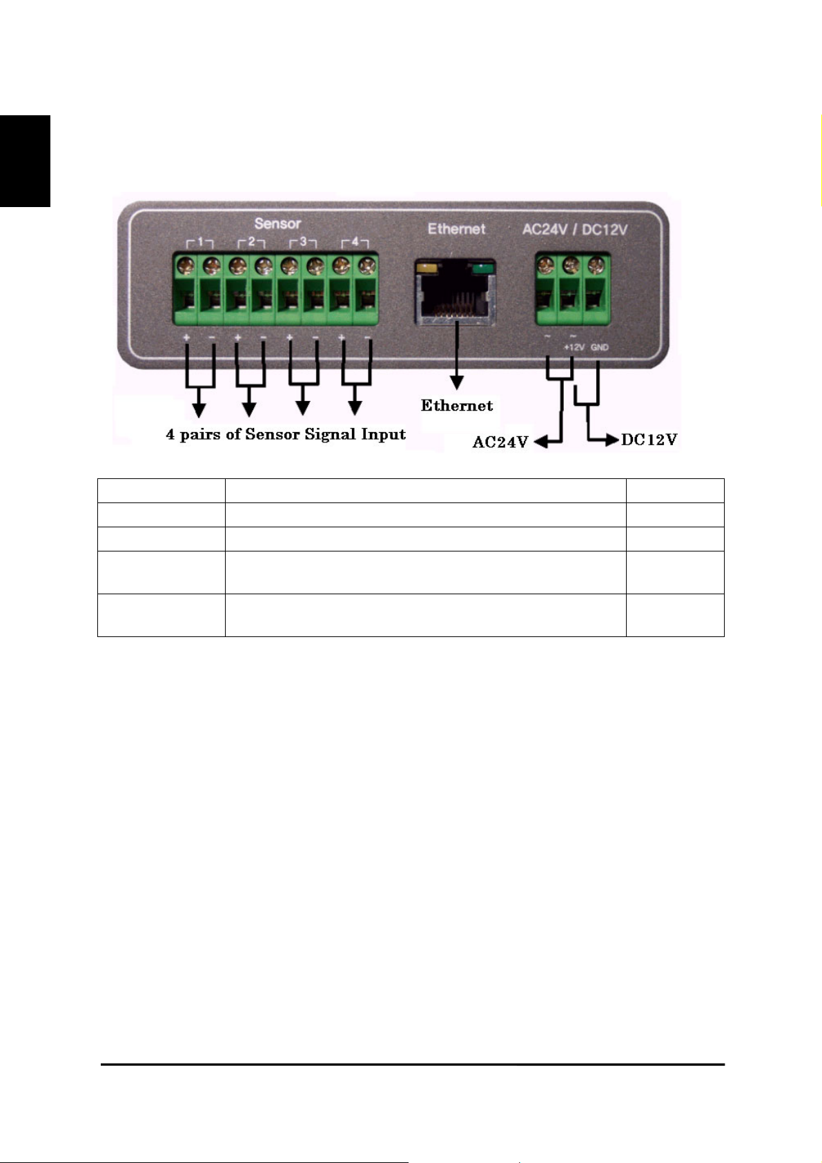
1) Front View and Description
connector description remarks
Sensor 4 pairs of connectors for sensor signal input
Ethernet Connector for connecting 10BASE-T ethernet cable Refer to 3)
AC 24V
DC 12V
Connector for connecting AC (alternate current) 24V power
supply unit
Connector for connecting DC (direct current) 12V power
supply unit
11
DX-VS1UE User’s Manual
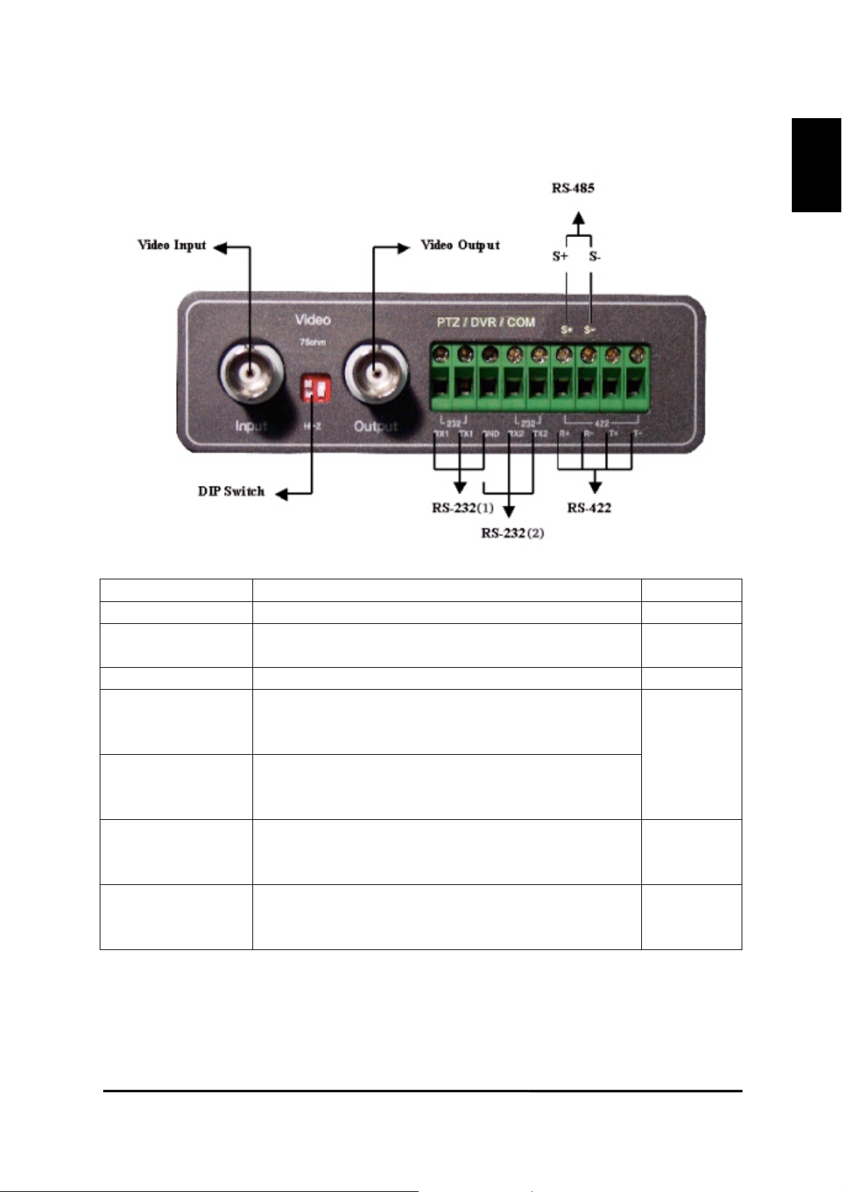
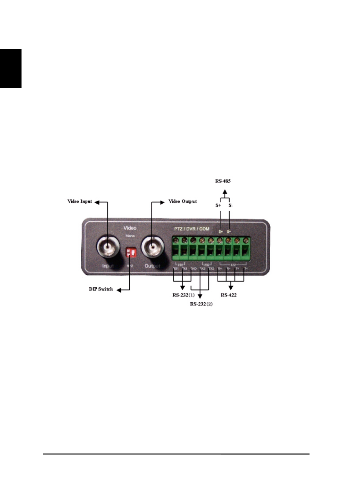
2) Rear View and Description
ENGLISH
connector name description remarks
Video Input Connector for inputting video signal using BNC cable
DIP Switch
Video Output Connector For outputting video signal using BNC cable
PTZ/DVR/COM
(RS-232(1))
PTZ/DVR/COM
(RS-232(2))
PTZ/DVR/COM
(RS-422)
PTZ/DVR/COM
(RS-485)
While you are using one of serial connecters among RS-232 (2), RS-422 and RS-485 connector,
you can’t use the other two connectors.
Switch for designating terminal of video signal of video
input BNC connector (Only left switch is used)
Connector for connecting DX-VS1UE with a digital recorder in order to operate the recorder. This consists of
RX1,TX1 and GND.
Connector for connecting DX-VS1UE with a
pan/tilt/zoom camera in order to operate the camera. This
consists of RX2,TX2 and GND.
Connector for communication between DX-VS1UE and a
pan/tilt/zoom camera that support RS-422 protocol. This
is half duplex and consists of R+,R-,T+ and T-.
Connector for communication between DX-VS1UE and a
pan/tilt/zoom camera that support RS-485 protocol. This
consists of S+ and S-.
Refer to 4)
GND terminal is
used in
common
12
DX-VS1UE User’s Manual
ENGLISH
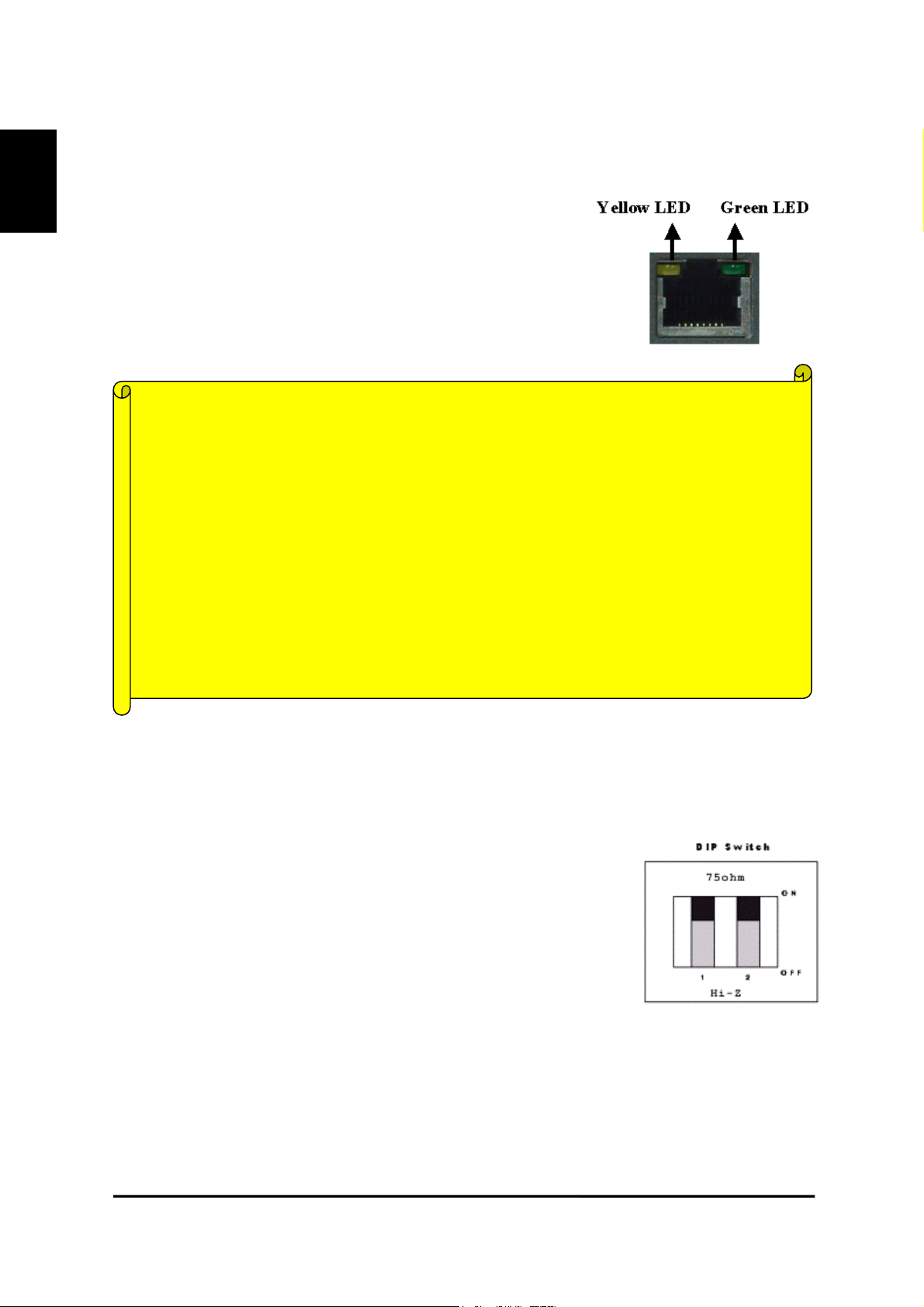
3) LEDs of Ethernet port
Yellow LED: This LED indicates the status of data transmission.
After power is supplied, it is on for the first 4-5 seconds and then it
goes off. And it blinks continuously when a user access DXVS1UE and DX-VS1UE transmits data.
Green LED: This LED indicates the status of networking. After
power is supplied, it is on for the first 1-2 seconds, and then it
blinks once at every one second as long as the network is connected.
Diagnostic information on failure using LED
Problem on Network
• Green LED blinks once every 4 seconds.
Check that ethernet cable is connected properly and network has no problem.
Problem on Hardware
• Neither Yellow LED nor Green LED light up at all.
Since DX-VS1UE is in unstable operation, restart DX-VS1 by supplying power again.
If DX-VS1UE would not restore regardless of restarting, stop using and contact with store.
4) Description of DIP Switches
This is used to designate video signal termination. If you want to monitor real time image through a
CCTV monitor as well as DX-VS1UE, connect a digital recorder to ‘Video Input’ connector and a
CCTV monitor to ‘Video Output’ connector. In this case, the terminal of video signal needs setting
properly.
If you connect a digital recorder to ‘Video Input’ and monitor real time
video only through a PC, place the left-hand side DIP switch at upper position ‘ON’ (the side of ‘75ohm’).
13
DX-VS1UE User’s Manual
V
Digital Video
V
Recorder
ideo signal flows via
LAN cable.
ENGLISH
Video signal flows via
BNC cable
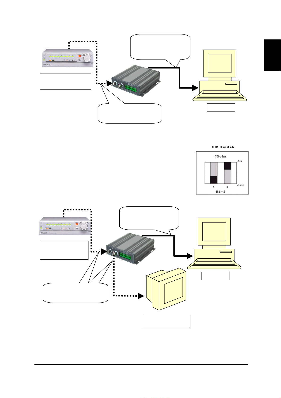
2. If you monitor real time video through a CCTV monitor as well as a PC,
connect a digital recorder to ‘Video Input’ and a CCTV monitor to ‘Video
Output.’ And place the left-hand side DIP switch at lower position ‘OFF’
(the side of ‘HI-Z’). CCTV monitor is set as termination of the video signal.
The right-hand side DIP switch is not available.
ideo signal flows via
LAN cable
PC
Digital Video
Recorder
Video signal flows via
BNC cable
PC
CCTV Monitor
14
DX-VS1UE User’s Manual
ENGLISH
III. DX-VS1UE Initial Configuration
1. Installation Summary
• Connect ethernet cable and supply power to DX-VS1UE on local network for configuration.
• Install a setup program of DX-VS1UE in a PC on local network.
• Assign an IP address to DX-VS1UE and set administrator condition.
• Set user condition.
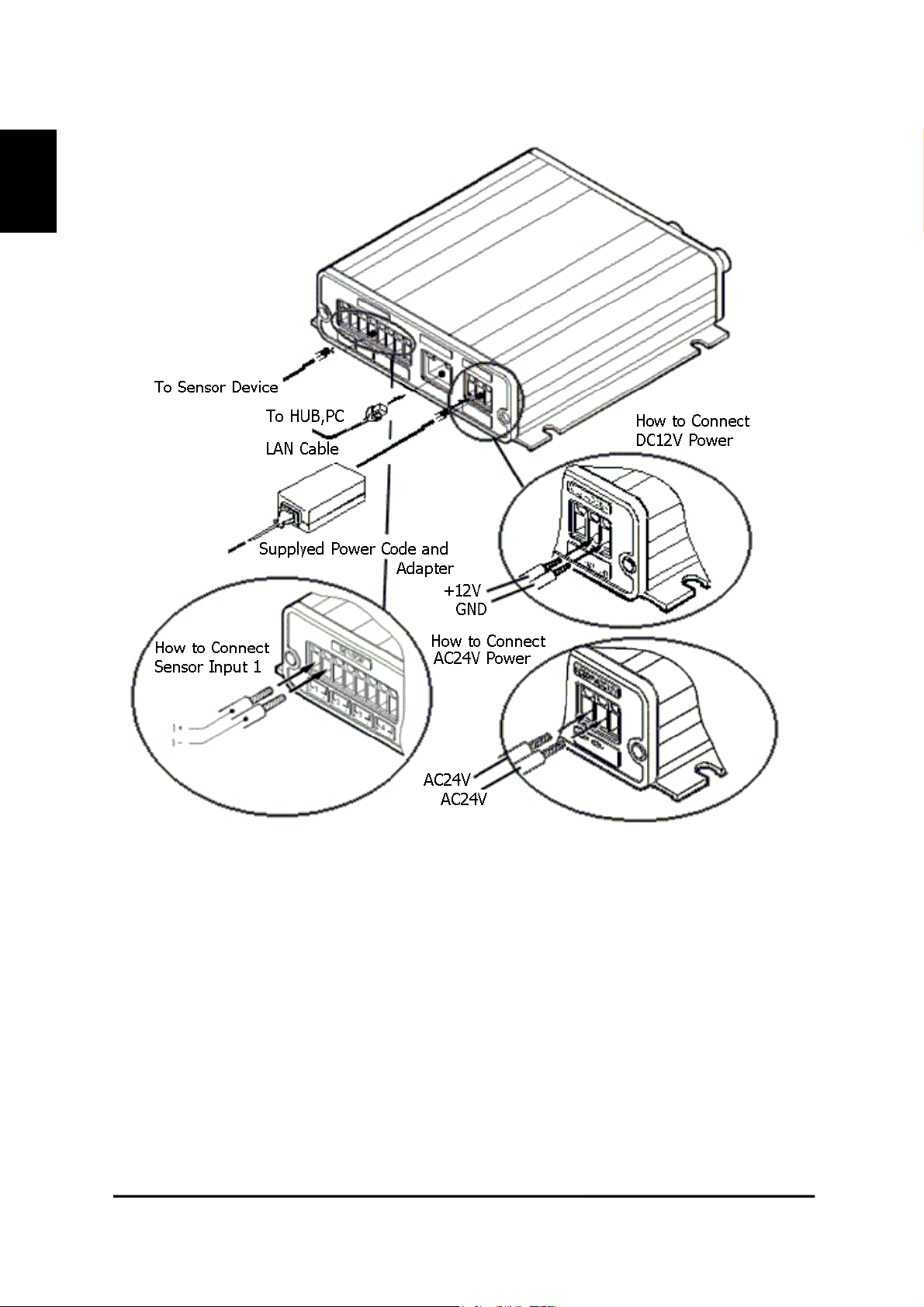
2. Connecting
•
Connect ethernet cable to the ethernet port on the rear.
• Connect power supply unit to a power supply port on the rear.
• Confirm that the LEDs of ethernet port keep blinking.
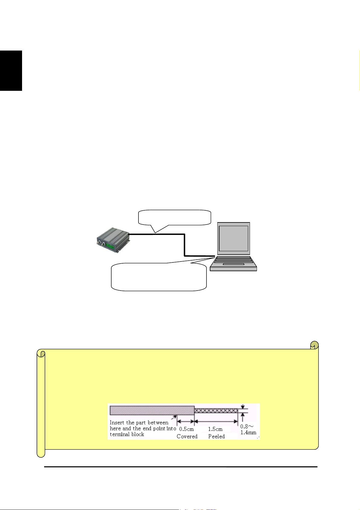
・Connecting DX-VS1UE with PC
You may use crossover cable (red colored one) to directly connect DX-VS1UE to a PC.
Crossover Cable
Connect DX-VS1UE directly to
PC through LAN ports.
*If you use the crossover cable (red colored one) enclosed and follow the method illustrated in the
above diagram, but you cannot access, try to connect through HUB using direct cable. Otherwise, set
10Mbps to the communication speed in terms of network interface configuration of your PC, if it’s
possible. In case you cannot access even though you tried the above mentioned method, something
can be wrong with PC (including OS setting). Please contact with makers that provide your PC or OS.
Note in connecting cable to terminal block
When you connect cable to terminal block, you should peel off the cover of cable by 1.5cm an
d insert the cable by 2cm into the terminal block. (communication., sensor input, alarm and et
c).The white line on cover of power cable indicates “+”.
15
DX-VS1UE User’s Manual
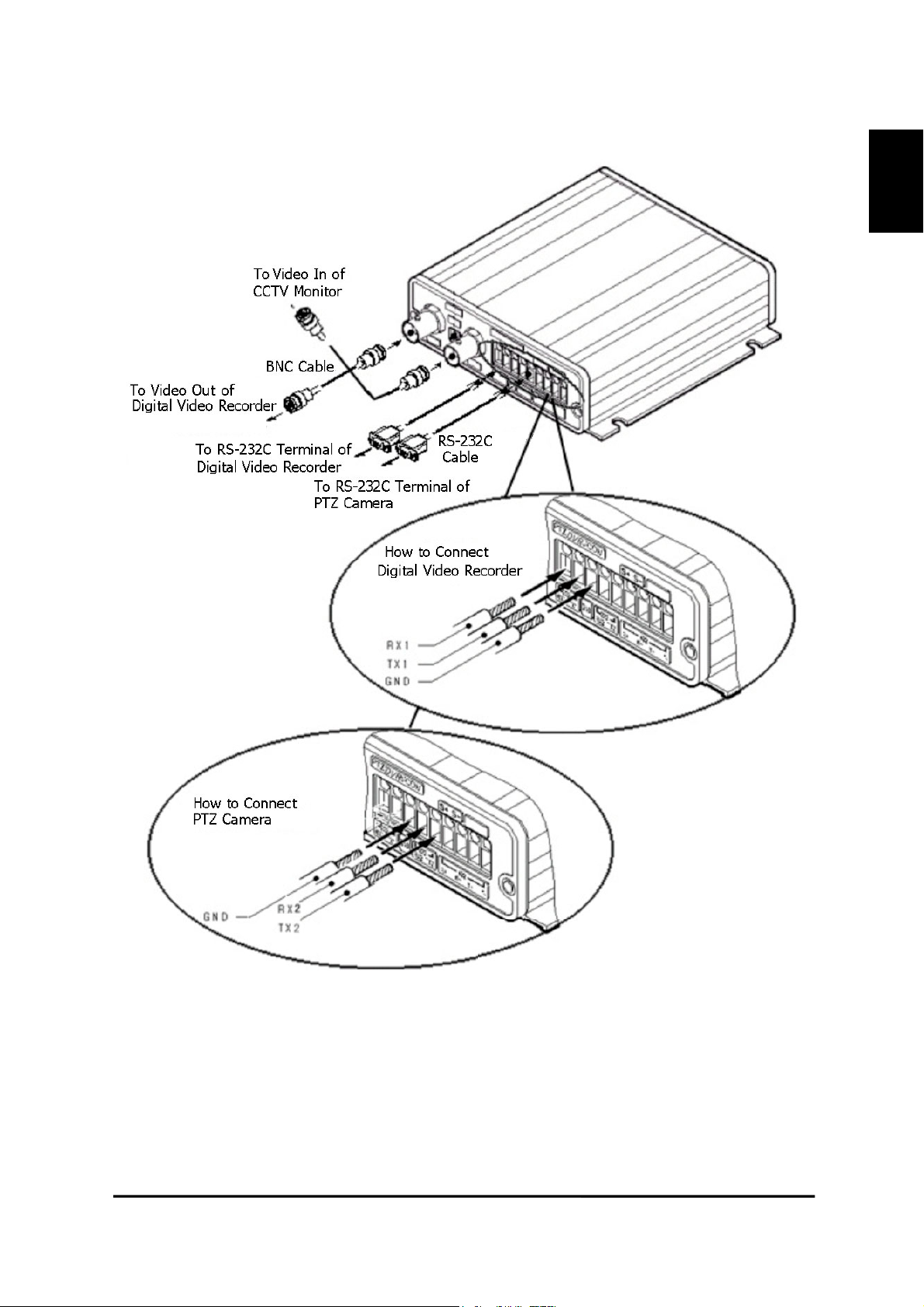
Illustration of the method of connection
ENGLISH
When you connect a cable to the terminal, fix the screw on the upper part of the terminal com-
pletely, after loosening the screw and inserting the cable. Please be careful not to short-circuit
adjacent cables. Also, please don’t twist each cable when wiring.
16
DX-VS1UE User’s Manual
ENGLISH
When you connect a cable to the terminal, fix the screw on the upper part of the terminal com-
pletely, after loosening the screw and inserting the cable. Please be careful not to short-circuit
adjacent cables. Also, please don’t twist each cable when wiring.
17
DX-VS1UE User’s Manual
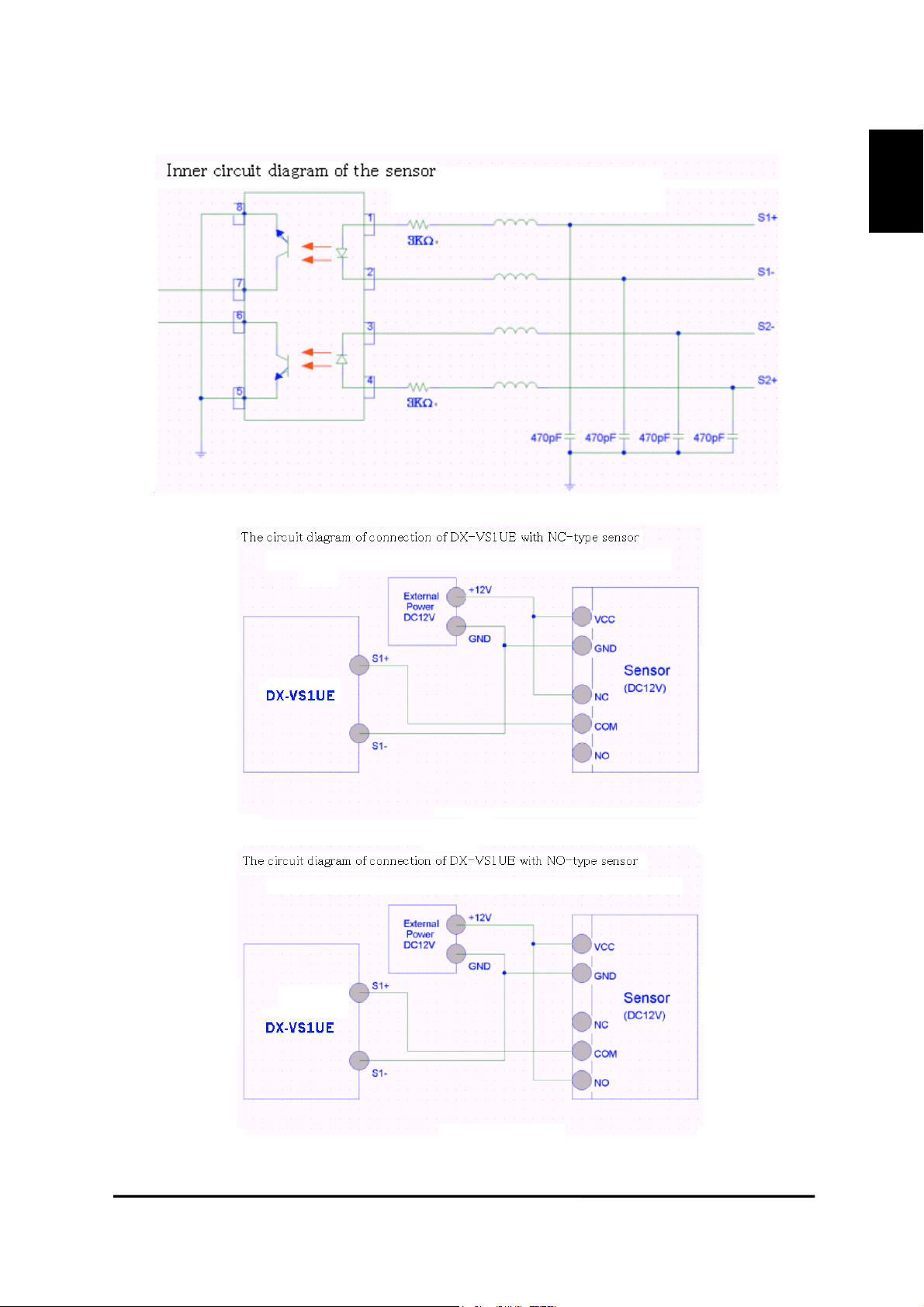
・ The circuit diagram of a sensor terminal.
ENGLISH
18
DX-VS1UE User’s Manual
3. Installing DX-VS1UE Setup Program
ENGLISH
• Copy DX-VS1Setup.exe file from the enclosed CD-ROM
• Click the file on your PC to run Setup program.
4. Assigning IP Address and setting Administrator Condition
* Important *
To access DX-VS1UE, you firstly have to assign an appropriate IP address.
When you assign an IP address to DX-VS1UE, make sure to use unoccupied
IP address.
For details, please ask your network administrator.
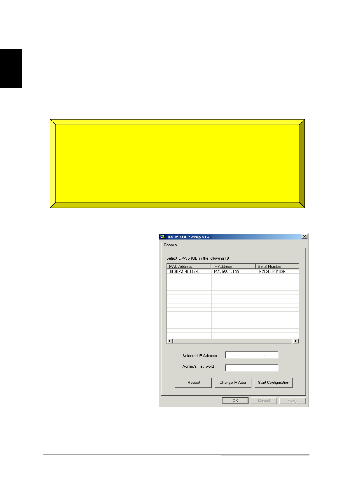
・Starting the Setup Program for DX-VS1UE
Run the “DX-VS1Setup.exe”. When the
setup program is started, the setup program detects and shows all DX-VS1UEs
connected with the local network.
Select one to assign a new IP address
from the DX-VS1UEs listed. (Default
value is 192.168.1.100) To select a DXVS1UE, click on its MAC Address or IP
address.
When a DX-VS1UE is selected, its IP
address will appear in the “Selected IP
Address” box. Enter a password in the
Admin’s Password box to change the IP
address, reboot DX-VS1UE, or start
configuration. The default password is
‘admin’.
19
DX-VS1UE User’s Manual
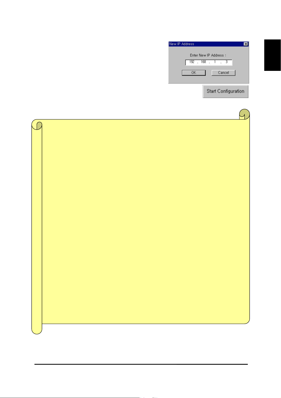
To change the IP address, enter the Administrator’s
password and press “Change IP Addr.” enter the new IP address and press “OK.” Button. The “Reboot” button will reboot the DX-VS1UE. This process takes 10-20 seconds.
・Setting Administrator Conditions
To access the Server Configuration Page in DX-VS1UE from the Setup Menu,
enter the admin’s password and press the “Start Configuration” button. (For
more detailed information, refer to Chapter V “Server Configuration Page”)
* Terminology *
IP Address
IP address is an identification code for computers and devices on a TCP/IP network.
Networks using TCP/IP protocol routes based on the IP address of the destination. IP
addresses can be assigned at random as long as each one is unique on closed network.
However, connecting a private network to the Internet requires using registered IP addresses to avoid duplicates. IP address can be acquired from a network administrator
or an Internet service provider.
ENGLISH
MAC Address (Media Access Control Address)
MAC address is a hardware identification code that uniquely identifies each node of a net-
work. The MAC layer directly interfaces with the network media. Consequently, each type of
network media requires a unique MAC layer. The MAC address of DX-VS1UE is composed
of 12-digit numbers. A unique MAC address can be found on the label at the bottom of each
DX-VS1UE.
Crossover Cable
The crossover cable (red) provided with the DX-VS1UE is used to connect DX-VS1UE with a
PC. A HUB is not necessary for connecting DX-VS1UE to a PC if a crossover cable is used.
Straight Cable
The straight cable (white) is used if a HUB is used as an intermediary between DX-VS1UE
and PC.
20
DX-VS1UE User’s Manual
ENGLISH
5. Connecting a digital recorder to DX-VS1UE
1) Connecting BNC cable
Connect one end of BNC cable with the video input connector of DX-VS1UE and the other end with
one of video output connector on the rear surface of digital recorder. Use 75ohm(3C-2V type or
more) type cable as BNC cable.
2) Connecting RS-232C cable
Connect RS-232C connector of a digital recorder to the RS-232(1) (refer to the following image)
connector of DX-VS1UE using the attached serial cable for digital recorder connection. One end of
the attached serial cable consists of three wires (red,yellow,black). Connect red wire to RX1, yellow
one to TX1 and black one to GND terminal. For connecting, loosen each fixing screw, insert three
wires into each terminal and fasten each fixing screw.
21
DX-VS1UE User’s Manual
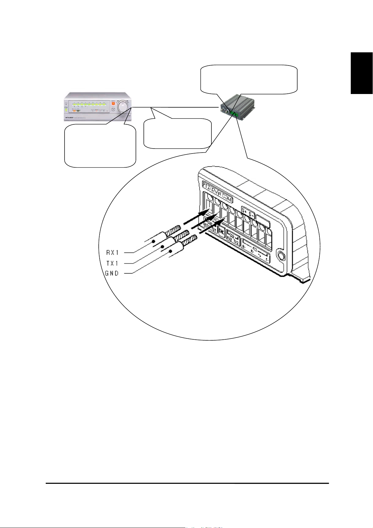
Connect to RX1,TX1,GND
of PTZ/DVR/COM terminal
ENGLISH
Connect to RS-232C
connector on the
rear surface
Supplied serial
cable
22
DX-VS1UE User’s Manual

g
)
p
ENGLISH
IV. Accessing DX-VS1UE Homepage & Monitoring Real-
time Image
After assigning IP address and gateway address, subnet mask, broadcast address to DX-VS1UE
properly, you may access DX-VS1UE and monitor real-time image on Internet.
1. Starting Web browser
Start your web browser and enter IP address assigned to DX-VS1UE. Then you can see the user login
page of DX-VS1UE.
• Ex)
http://192.168.1.100/
DX-VS1UE supports up to 100 simultaneous accesses. But, the larger the number of simultaneous
access user gets, the slower the monitoring rate of real-time image gets.
2. Composition of a screen
User Login Page (This
age appears firstly when
you access DX-VS1UE.)
Simple Viewer Page (refer
to chapter IV “Accessing
DX-VS1UE Homepage &
Monitoring Real-time
Ima
e”
23
DX-VS1UE User’s Manual

DVR/PTZ level login
p
age
DVR/PTZ control page
(refer to 5.DVR/PTZ
control page)
ENGLISH
DVR configuration level login page
Server configuration
level login page
24
DX-VS1UE User’s Manual

ENGLISH
DVR configuration page
(refer to 6.DVR configuration page)
Server configuration page
(refer to chapter V “Server
Configuration page”)
25
DX-VS1UE User’s Manual

3. Login Page
1) Login to the simple viewer page
This login page is used for authenticating registered user. Connect DXVS1UE, enter each password in both
password1 field and password2 field
and press “LOGIN” button, you can
access to the simple viewer page.
Each default value of password1 and
password2 is not set respectively (i.e.
The default value for password1 and
that for password2 are null strings).
Administrator can change the passwords. Each password needs to be
composed of less then or equal to 9
characters.
2) Logging into DVR/PTZ control page
After logging into the Simple Viewer page, the login screen of DVR/PTZ Control page will appear if you press the DVR control button. The button is located
at the lower part of the Simple Viewer page.
In order to log into the DVR/PTZ Control page, please input a password for the DVR/PTZ Control
page. The default value of the password is not set up. It can be changed with the Password Configuration of the Server Configuration page.
ENGLISH
3) Logging into the DVR Configuration Page
After logging into the DVR/PTZ Control page, the login screen of DVR configuration page will appear if you press the DVR configuration button. The
button is located at the lower part of the DVR/PTZ Control Page.
In order to log into the DVR configuration page, please input a password for the DVR Configuration
Page. The default value of the password is “admin”. It can be changed with the Password Configuration of the Server Configuration Page.
26
DX-VS1UE User’s Manual

ENGLISH
4) DX-VS1UE ActiveX
For monitoring image, ActiveX Control program is required. The program is installed automatically
when a user accesses to DX-VS1UE. For ActiveX installation on your PC, just click ‘Yes’ to the
question about whether you would like to install and run this program. If you install ActiveX and you
can’t see image, confirm that ActiveX is installed properly (File name: Web Camera Server Control).
You can see it on c:\Windows\Downloaded Program Files (or C:\WinNT\Downloaded Program Files)
folder. If the ActiveX program is not installed, try to download and install again. If the ActiveX is installed, remove the file and re-install.
27
DX-VS1UE User’s Manual

4. Real Time Monitoring at the Simple Viewer Page
ENGLISH
A user can change the configuration of frame rate, image resolution or color mode by operating the
button or bar at the lower part of the simple viewer page. Also, you can monitor image in server push
mode by pressing server push button
Pressing DVR control button, you are moved to the login page for dvr/ptz control page.
• Server Push Mode
If DX-VS1UE is connected to network protected by firewall and image of DX-VS1UE cannot be
seen from PC located at the outside of the network, press server push button and change into server
push mode. Image of DX-VS1UE would be seen from the PC. ”Image Quality” control, “Focus Area”
control and “Focus Sensitivity” control is not supported in this mode.
1) Image control
There are three menus for controlling image display.
(1) Frame Rate
You can select image transmission speed among 1fps, 5fps, 10fps, 15fps and no limit. If you select
“no limit”, DX-VS1UE transmit image as fast as possible depending on network environment. Frame
rate is actually dependant on both network environment and performance of PC. DX-VS1UE can
transmit at up to 30 frames per second.
28
DX-VS1UE User’s Manual

(2) Resolution
Select resolution among 720x486, 720x243, 360x243, 180x121 and 90x60. If you select higher resolution, you will see image at slower speed because of larger data transmission.
ENGLISH
(3) Black and White (Gray) mode
If you press this button, monochrome image is displayed. Transmission rate in monochrome mode is
faster than that in color mode. You will be moved back to color mode by pressing the button again.
2) Pop-Up Menu
If you right-click, a small window with 5 menus appears (upper right image). 4 functions except “Save As File” are available for only server configuration level users. Only “Image Info” menu and “Save As File” menu
are available in server push mode. (lower right image)
(1) Image Info
You can decide the color (black or white) of the information that is shown on the left
top of image. And you can leave out the information.
(2) Quality Box
This is used to make certain area clear and blur remained area. You can
overcome insufficient network bandwidth with this function, because data
size is reduced due to unfocused area. Quality Box can be set as follows.
• Click “New QBOX”
• Place mouse cursor on the top left point of QBOX you
would like to set and click.
• Drag with the mouse to the lower right point of QBOX you
would like to set.
You can also re-use previously focused area by clicking “Enable QBOX”. You can stop using QBOX function to click “Disable QBOX”. The image in the right
shows what QBOX-enabled image is like. The image quality of outer part of QBOX can be set with
“Ambient Level” menu. The level can be select from 1 to 5. If you select “Level 1”, the quality is
similar to QBOX area. And if you select “Level 5”, the outside of QBOX area is shown dark.
(3) Focus sensitivity
You can set the degree of movement of zoom mechanism. Sensitivity is selectable
from “level0” to “level9”. If you select higher level, zoom interval gets larger.
(4) Image quality
This is used to set image quality. Image quality is selectable from “level0” to
“level9”. If you select higher level, DX-VS1UE transmits higher quality image.
However, transmission frame rate would be slower due to larger data size.
29
DX-VS1UE User’s Manual

(5)Save As File
This is used to capture image. Still image can be saved in the form of bitmap (*.bmp) file or Wavelet
format file (*.eye). Wavelet formatted image file can be seen using Internet Explorer if you’ve installed DX-VS1UE ActiveX on your PC. The image shown at the moment when you click the menu is
saved.
3) Real time monitoring in Server Push Mode
If DX-VS1UE is installed on network in which firewall is installed, you may access DX-VS1UE in
Server Push Mode to monitor real-time images. If you have information on the network, such as
which port is blocked with firewall, you may access with default mode by changing Web TCP port or
video TCP port. For changing TCP port, refer to Chapter V “Server Configuration Page.”
(1) Image Control
1. Frame Rate
You can select image transmission speed among 1fps, 5fps, 10fps, 15fps and no limit.
2. Resolution
You can select resolution level among 90x60, 180x121, 360x243, 720x243 and 720x486.
3. Black and White (Gray) Mode
If you choose this mode, Images are displayed in black and white. Also, you can view images at
higher speed in comparison with color mode.
ENGLISH
(2) Pop-up Menu
1. Image Info
You can select the color of the caption shown on the left top of image between white and black. Also,
you can leave out the information.
2. Save As File
This is used to capture image. Still image can be saved in the form of bitmap (*.bmp) file or Wavelet
format file (*.eye). Wavelet formatted image file can be seen using Internet Explorer if you’ve installed DX-VS1UE ActiveX on your PC. The image shown at the moment when you click the menu is
saved.
“Image Quality” “QBOX setting” and “Focus Sensitivity” are not supported in server push mode.
4) DVR Control Button
If you press this button, you are moved to the login page for DVR/PTZ Control page. In case you’ve
logged into DVR/PTZ control page and the session is not expired, you are directly moved to
DVR/PTZ control page.
5) Capture Button
This is used to capture image and save it as an image file. This button serves the same function as
“Save As File” menu in the Popup menu.
30
DX-VS1UE User’s Manual

ENGLISH
5. DVR/PTZ Control Page
You cannot only monitor image but also operate a digital recorder connected with DX-VS1UE remotely. Besides, you can operate pan/tilt/zoom function of a camera with pan/tilt/zoom mechanism, if
the camera is connected to DX-VS1UE.
Furthermore, you can select resolution, frame rate and color mode similar to the Simple Viewer Page.
If you press DVR configuration button, you are moved to the login page for DVR configuration page
illustrated at the next section.
The buttons for operation of pan/tilt/zoom mechanism and digital recorder is explained below.
1) Pan/Tilt/Zoom mechanism
There are 3 button groups in the left hand of screen. The upper button group is used to control
pan/tilt/zoom mechanism. Each of buttons has the functions illustrated below.
name function
Tilt Up
Tilt Down
Move the direction of camera in upper direction。
Move the direction of camera in lower direction。
31
DX-VS1UE User’s Manual

Pan Left
Move the direction of camera in left direction。
Pan Right
Focus Far Move the focus point far.
Focus Near Move the focus point close.
Zoom WIDE Serves as the zoom out function.
Zoom TELE Serves as the zoom in function.
User button A
User button B
User button C
User button D
Move the direction of camera in right direction。
Execute the command defined by administrator in the server
configuration page.
Execute the command defined by administrator in the server
configuration page.
Execute the command defined by administrator in the server
configuration page.
Execute the command defined by administrator in the server
configuration page.
2) Digital Recorder Control mechanism
The Middle part group is used to control digital recorder. Each of buttons has the functions illustrated
below.
name function
ENGLISH
Playback Play in forward direction
Reverse Playback Play in backward direction
Get digital recorder to switch to still frame playback. To resume
Pause
Stop Stop playback.
Reverse Search Play in reverse direction at high speed
Forward Search Play in forward direction at high speed
One Picture Reverse Play in backward direction in single frame.
One Picture Advance Play in forward direction in single frame.
Cursor Up Move the cursor up
Cursor Down Move the cursor down
Back Return to previous screen on search screen of digital recorder
playback, press the “Pause” button again or press “Playback” button.
32
DX-VS1UE User’s Manual

Enter Set the setting item on search screen of digital recorder.
Search Display the search menu to search image.
ENGLISH
Split/Sequence Show image in split or sequential mode.
Zoom Zoom in displayed image
Displays image of the camera with the corresponding camera num-
Camera number button
*The layout of buttons can get out of shape when accessing the DVR/PTZ control page. In this
case, please use the reload button of Internet browser.
*DVR is the abbreviation for digital video recorder DX-TL800E.
*For detailed information on the operation of digital recorder, refer to the instruction manual
for digital recorder DX-TL800E.
ber assigned. In zoom mode, each of buttons 1,2,3 and 4 has the
function to move the magnification central point to the left, to the
right, up and down respectively.
33
DX-VS1UE User’s Manual

6. DVR Configuration Page
ENGLISH
This page is used for not only monitoring image but also using several functions of DVR such as
power on/off, recording, timer recording, lock, password lock and etc.
In addition, you can select frame rate, resolution and color mode similarly with the Simple Viewer
Page. Also, you are moved to the login page for the server configuration page that illustrated at the
next section, if you press server configuration button. Furthermore, you are moved back to the Simple
Viewer Page, if you press simple viewer page button.
The buttons for DVR configuration are explained below.
*DVR is the abbreviation for digital video recorder DX-TL800E.
name function
Move cursor up on the menu screen of digital recorder (Move
Cursor Up
Cursor Down
cursor to the left on certain setting such as password lock configuration)
Move cursor down on the menu screen of digital recorder
(Move cursor to the right on a certain setting such as password
lock configuration)
34
DX-VS1UE User’s Manual

ENGLISH
Back
Enter Set the setting item on the setting screen of digital recorder.
Power ON/OFF Power on or off DX-VS1UE
Recording Stop Stop recording
Recording Start Start recording
Timer Recording ON Enable timer recording.
Timer Recording OFF Disable timer recording
Warning Reset Clear on-screen warning display and clear data.
Lock ON/OFF
Password Lock ON/OFF
Move back to previous screen on the menu screen of digital
recorder.
Enable or Disable the simple lock function. Enabling the simple lock function disables the operation of any buttons except
for split/sequence button, camera number button, zoom button
and power on/off of digital recorder.
Enable or Disable the simple lock function. Enabling the simple lock function disables the operation of any buttons except
for split/sequence button, camera number button, zoom button
and power on/off of digital recorder. Password is necessary for
release of the password lock.
OSD ON/OFF Show the menu screen of digital recorder.
In zoom mode, move the magnification central point to the
Left
Right
Up
Down
left. Normally, this button is used to display image of the camera whose number is 1.
In zoom mode, move the magnification central point to the
right. Normally, this button is used to display image of the
camera whose number is 2.
In zoom mode, move the magnification central point up.
Normally, this button is used to display image of the camera
whose number is 3.
In zoom mode, move the magnification central point down.
Normally, this button is used to display image of the camera
whose number is 4.
35
DX-VS1UE User’s Manual

V. Server Configuration Page
This page is for administrator of DX-VS1UE. Administrator can manage DX-VS1UE remotely. Also.
This page can be accessed from the Setup Program by pressing “Start Configuration” button.
1. Administrator Login
1) Access from the Setup Program
Firstly, select MAC address or IP address of DX-VS1UE listed in the Setup Program. After that, enter
the password for server configuration page (default password is “admin”) and press the “Start Configuration button”. Then, you are moved to the server configuration page automatically. (For further
information on how to access the server configuration page through the Setup Program, please refer to
chapter III “DX-VS1UE initial configuration”).
2) Access using only Web browser
Move to the DVR configuration page
and press server configuration button,
and you can access to the login page
for the server configuration page. You
need to enter password for the server
configuration page (default password
is “admin”) in order to access to the
server configuration page.
ENGLISH
Password for server configuration
page can be set at password configuration page. Password needs to be
composed of up to 9 characters.
There are 11 sub pages in the server configuration page. You can set management condition of DXVS1UE through them. For using DX-VS1UE properly, it’s important to set the condition properly. If
your configuration is wrong, there is a possibility that DX-VS1UE cannot be accessed. Please make
great attention to set up
36
DX-VS1UE User’s Manual

2. Description on setting items
ENGLISH
1) System Configuration
This page is used for setting Video
Server Box name, Date&Time, Installation Location and Additional
Description. Model name, serial number and the version of software are
displayed automatically.
(1) Video Server Box Name
This information is displayed at the
simple viewer page.
(2) Model
Clicking “Detailed H/W Information”,
you can refer to detailed hardware information such as video decoding format, serial port and sensor input. Model name is displayed
automatically.
(3) Installation Location and Additional Description
This information is displayed at the simple viewer page.
(4) Date&Time
There are three kinds of DATE&TIME menus. The date and time set to DX-VS1UE are displayed in
the “VSB Current Date&Time” field. The date and time set to your PC are displayed in the “System
(PC) Current Date&Time” field. Furthermore, Administrator can set the date and time to DX-VS1UE,
pressing “Time Synchronization” button. Administrator also can manually set date and time in the
“Manual Date&Time Setting” field. By pressing the “Time Synchronization” button, administrator
can set the date and time to DX-VS1UE.
*VSB is the abbreviation for digital video recorder Video Server Box.
* Notice for Time Setting *
After setting time and date manually at the System Configuration, please don’t reboot
DX-VS1 within one minute. If you reboot within one minute, your setting would not be
applied. Slightly delayed time may be set depending on network environment.
(5) Factory Setting
This function initialize almost all of information stored in flash memory except for Date&Time,
Model, Serial Number, IP addresses at network configuration page and video signal type at video
configuration page.
37
DX-VS1UE User’s Manual

(6) Reboot (Forcibly)
d
In case there is some problem on DX-VS1UE, you can reboot DX-VS1UE without disconnecting
power from DX-VS1UE.
2) Password Configuration
You can set passwords for the simple
viewer page, dvr/ptz control page,
DVR configuration page and server
configuration page in this menu.
User level means authority for accessing each page. User level is composed of Server Configuration password (Authority to access the Server
Configuration page), DVR Configuration password (Authority to access the DVR Configuration
page), DVR/PTZ Control password (Authority to access the DVR/PTZ Control page), and Simple
Viewer password1 and password2 (Authority to access the Simple Viewer page).
The default value of server configuration password and DVR configuration password is “admin” respectively. The default value of each password for the simple viewer page and the dvr/ptz control
page is not set, that is, the default value is null string.
ENGLISH
*DVR is the abbreviation for digital video recorder DX-TL800E.
Notes of password
z It is important to compose the passwords within 9 alpha-numeral characters.
z You are encouraged to change the passwords firstly for protection from unauthorize
access
z It is effective to change the passwords periodically just in case of leaking of pass-
words.
38
DX-VS1UE User’s Manual

ENGLISH
3) Network Configuration
This page is used to define network type and set network addresses of DX-VS1UE.
(1) DHCP Client Protocol
DHCP (Dynamic Host Configuration Protocol) is used to manage host address on a network. With t
his protocol, every host on a LAN may share limited official IP address for Internet access. In other
words, every host on a LAN may lease official IP address from DHCP server temporarily. Exactly s
peaking, DHCP server assigns a certain host with an official IP address that is not occupied by other
hosts on the LAN.
DHCP server will assign DX-VS1UE with an official IP address if the LAN is equipped with DHCP
server and “DHCP Client Protocol” is activated.
“DHCP Client Protocol” is used on LAN environment where a DHCP server is in operation. Normal
ly, medium or large sized company runs a DHCP server on LAN environment. For the small sized L
AN, it would be better to use NAT function of HUB.
※ If “DHCP client protocol” is enabled in the network where the DHCP server is not working,
the IP address of DX-VS1UE may become unfixed. In this case, directly connect the DX-
VS1UE to a PC on which the setup program was installed by a crossover cable, start the set-
up program, and set IP address again.
(2) Select Network Interface
This is used to select proper netw
ork interface with which DX-VS1
UE is connected.
If DX-VS1UE is connected with Internet dedicated line, cable modem line or LAN environment, yo
u should select network interface as ‘Ethernet’.
If DX-VS1UE is connected on xDSL line that needs PPPoE process to connect on Internet, administ
rator should select ‘xDSL (PPPoE)’. However the xDSL line doesn’t need PPPoE process, administr
ator should select ‘Ethernet’ even though DX-VS1UE is connected on xDSL line.
In order to get your DX-VS1UE accessed from the Internet, you need to make a contract with ISP and
get a global IP address for your DX-VS1UE.
39
DX-VS1UE User’s Manual

(3) Ethernet Interface
Administrator can set up IP address, subnet mask, broadcast
address, gateway address, and
DNS addresses of DX-VS1UE.
For broadcast address, administrator can set it automatically
by clicking “Get From Netmask” button after assigning IP
address and subnet mask.
When the addresses are not assigned properly, any user cannot access DX-VS1UE from
local or remote network. Even on the local network, a user is not able to access if administrator does not assign a proper IP address to DX-VS1UE.
This interface is mainly used for the Internet dedicated line and LAN.
MTU Size: Depending on network type, administrator can set data packet size with this menu to use
the network effectively.
DNS Server IP Address: This is the information required to set up the E-mail function or the FTP
function using a domain name instead of an IP address.
ENGLISH
DNS (Domain Name System)
DNS (Domain Name System) is to map between IP address and domain name. Every
network device on the world has its IP address to be connected on Internet. And the
device is to be connected not with its domain name but with its IP address. Common
users are not familiar with IP addresses but with domain names.
If a user accesses a certain network device with its domain name, DNS server resolves the d
omain name into an IP address of the device and replies the result to the user. A lot of DNS s
ervers are run on Internet worldwide.
40
DX-VS1UE User’s Manual

ENGLISH
(4) xDSL Interface
If DX-VS1UE is connected on x
DSL line and needs PPPoE proce
ss, administrator should select net
work interface as ‘xDSL (PPPo
E)’. And administrator should set
user ID and password for PPPoE.
ID and password may be acquiredD and password may be acquired from your ISP that installed the line. And DX-VS1UE can get an I
P address when it is connected on xDSL line.
4) Security Configuration
This is to filter a certain IP addresses from accessing DX-VS1UE based on network masking.
(1) IP/Subnet Filtering Mode
You may allow or deny a certain user to
access your DX-VS1UE with enabling this
menu.
Default Policy
This is used to decide the principle of
“IP/Subnet Filtering Mode” between allow
and deny.
If you allow anyone except a few users to
access your DX-VS1UE, you should select
default policy as ‘allow’ and register a few
users as denied users. If you deny all users
except for a few users to access your DXVS1UE, you should select default policy as ‘deny’ and register a few users as allowed users.
How to register allowed/denied user in the list
IP address masking Allow/Deny
Network masking is used to mask network ID for every existing IP address in the world.
Therefore, the IP addresses that have the same network ID are applied with a command of
‘Allow’ or ‘Deny’. The masked bits are considered as network ID.
If a masking number is 4, the 4 bits from the first bit are masked as network ID comparing with the
provided IP address before, and any IP address that has the same binary number on the first 4 bits are
to be filtered from DX-VS1UE.
Note: To explain and understand easily on IP address, the first byte of IP address is marked as
41
DX-VS1UE User’s Manual

X1 in this manual. And X2 is for the second byte, X3 is for the third byte, and X4 is for the
fourth byte.
IP address is constructed as follows.
IP address construction in binary number of each bit
xxxxxxxx (8 bit): X1 xxxxxxxx (8 bit): X2 xxxxxxxx (8 bit): X3 xxxxxxxx (8 bit): X4
272625242322212027262524232221202726252423222120272625242322212
E.g. IP address in binary: 11000000. 10101000. 00000001. 00001101 (It is equal to 192.168.1.13)
* Binary number 1 means to take the equivalent decimal number (2
7
, 25, etc) and 0 means to disregard it.
0
IP address construction in decimal number of each byte
xxx (0-255: 1 byte): X1 xxx (0-255: 1 byte): X2 xxx (0-255: 1 byte): X3 xxx (0-255: 1 byte): X4
128 64
E.g. IP address in decimal: 192. 168. 1. 13 (It is equal to 11000000. 10101000. 00000001. 00001101)
* Binary number 1 means to take the equivalent decimal number (2
32 16
8 4 2 1 128 64
32 16
8 4 2 1 128 64
32 16
8 4 2 1 128 64
7
, 25, etc) and 0 means to disregard it.
32 16
8421
Network masking point is to be expressed with decimal number from 0 to 31. IP address is consisted
in 4 bytes. 4 bytes are 32 bits. Network is to be masked on every bit from the first bit to the 32nd bit.
Masked bit is marked with binary number ‘1’, and the corresponding bits out of provided IP address
are defined as network ID for IP filtering.
ENGLISH
42
DX-VS1UE User’s Manual

ENGLISH
Network masking point (0 to 31)
123456789101112131415161718192021222324252627282930310
E.g. Network masking on the 8th bit (8): 11111111. 0000000. 00000000. 00000000 (255.0.0.0)
th
E.g. Network masking on the 16
E.g. Network masking on the 24
E.g. Network masking on the 32
bit (16): 11111111. 11111111. 00000000. 00000000 (255.255.0.0)
th
bit (24): 11111111. 11111111. 11111111. 00000000 (255.255.255.0)
nd
bit (0): 11111111. 11111111. 11111111. 11111111 (255.255.255.255)
According to masking point, masked network ID is to be different out of the same IP address. For example, if IP address is described as 192.168.1.13 (11000000.10101000.00000001.00001101) with
masking point 24 (255.255.255.0), the IP addresses whose IP address is consisted with
‘11000000.10101000.00000001.xxxxxxxx’ (2
8
(256) pieces of IP addresses) will be allowed or de-
nied from DX-VS1UE.
If you describe an IP address as 192.168.1.13 and put masking point 26 (255.255.255.192), the mas
ked bits are the first 26 digits and network ID masked as ‘11000000.10101000.00000001.00’. In thi
s case, the IP addresses whose IP address is consisted with ‘11000000.10101000.00000001.00xxxxx
6
x’ (2
(64) pieces of IP addresses) will be applied with a command of ‘Allow’ or ‘Deny’.
Applied IP address number according to masking point
1 2 3 4 5 6 7 8 9 10111213141516171819202122232425262728293031 0
2312302292282272262252242232222212202192182172162152142132122112102928272625242322212
E.g. Masking point 8: 2
E.g. Masking point 16: 2
E.g. Masking point 24: 2
E.g. Masking point 0: 2
24
pieces of IP addresses are applied
16
pieces of IP addresses are applied
8
pieces of IP addresses are applied
0
pieces of IP address (itself) is applied
0
Though masking point is to be any bit out of 32 bits, it is common to point on the bits of host ID part.
If the masking point is placed on network ID part, the range is expanded compared to the provided IP
address.
Network class is divided as follows. D and E class networks are not to be used by normal user.
Class Decimal number of X1 byte Network ID Host ID
A 0 to 127 X1 X2, X3, X4
B 128 to 191 X1, X2 X3, X4
C 192 to 223 X1, X2, X3 X4
D 224 to 239 For Multicasting utilization
E 240 to 255 Reserved for specific utilization
In C class network, the applied number of IP addresses with network masking is as below when you
43
DX-VS1UE User’s Manual

mask on host ID part (X4: the fourth byte).
Masking on X4 Byte Remark Host ID number
25 26 27 28 29 30 31 0 Masking Point
128
(128)64(192)32(224)16(240)8(248)4(252)2(254)1(255)
Masked Free Free Free Free Free Free Free 7 digits are free 27 = 128
Masked Free Free Free Free Free Free 6 digits are free 26 = 64
Masked Free Free Free Free Free 5 digits are free 25 = 32
Masked Free Free Free Free 4 digits are free 24 = 16
Masked Free Free Free 3 digits are free 23 = 8
Masked Free Free 2 digits are free 22 = 4
Masked Free 1 digits are free 21 = 2
Masked
Decimal Number
(Accumulated
Val ue )
No free digit
20 = 1
The most common case is to make subnet through network masking, and it is to divide a network into
some smaller network. If provided IP address is 192.168.1.100, you may divide the whole network
into 2 sub-networks and allow or deny only the IP addresses that belong to one of sub-networks.
With setting as follows, The IP address of 192.168.1.100 is divided into two sub-networks and allow
for the IP address out of the first sub-network to access DX-VS1UE.
ENGLISH
• Default Policy: Deny
• IP address: 192.168.1.100
• Masking: 25 (255.255.255.128)
• Then only the IP addresses from 192.168.1.0 to 192.168.1.127 are to access DX-VS1UE, while
the IP addresses from 192.168.1.128 to 192.168.1.255 and any other IP address are to be denied
accessing DX-VS1UE.
Changing IP address can reverse the result. If you set IP address as 192.168.1.130, only the IP addresses from 192.168.1.128 to 192.168.1.255 are to access DX-VS1UE. And the IP addresses from
192.168.1.0 to 192.168.1.127 and any other IP address are to be denied accessing DX-VS1UE.
You may refer below table to figure out masking point from network information that is given from
your ISP or network administrator.
44
DX-VS1UE User’s Manual

ENGLISH
Masking Point Masked bit (Network ID) Netmask in decimal number
1 The first bit 128.0.0.0
2 From the first bit to the second bit 192.0.0.0
3 From the first bit to the third bit 224.0.0.0
16
17
.
8
9
.
From the first bit to the 8
From the first bit to the 9
.
From the first bit to the 16
From the first bit to the 17
.
.
th
th
bit
bit
th
th
bit
bit
.
255.0.0.0
255.128.0.0
.
255.255.0.0
255.255.128.0
.
24 From the first bit to the 24th bit 255.255.255.0
25 From the first bit to the 24th bit 255.255.255.128
26 From the first bit to the 26th bit 255.255.255.192
27 From the first bit to the 27th bit 255.255.255.224
28 From the first bit to the 28th bit 255.255.255.240
29 From the first bit to the 29th bit 255.255.255.248
30 From the first bit to the 30th bit 255.255.255.252
31 From the first bit to the 31st bit 255.255.255.254
0The 32
nd
bit 255.255.255.255
* Masking on 32nd bit has the same effect as masking none, and in DX-VS1UE 0 instead of 32 is used.
Masking 32 bits means that all the 32 bits are network ID, and masking none means that all the 32 bits are
host ID. Therefore masking all the 32 bits or none means that the provided IP address itself is applied with
a command of ‘Allow’ or ‘Deny’.
If you want to allow only the IP addresses from 192.168.1.61 to 192.168.70, you may set as follows
Default Policy
IP address
IP address
IP address
IP address
192.168.1.60 Masking 30 Policy Allow
192.168.1.60 Masking 0 Policy Deny
192.168.1.64 Masking 29 Policy Allow
192.168.1.71 Masking 0 Policy Deny
Deny
* The IP addresses in black squares can be any IP address of the sub-networks. In the first square,
192.168.1.60 to 192.168.1.63 is to be assigned. And in the second square 192.168.1.64 to
192.168.1.71 is to be assigned.
Principle in filtering
The sub-network range is smaller; the priority in filtering is earlier. Therefore a single IP a
ddress (masking with 0) has the first priority.
45
DX-VS1UE User’s Manual

(2) Image Encryption Mode
Administrator can restrict people who can receive images from DX-VS1UE.If “Image Encryption
Mode” is enabled and a pin number is assigned, the assigned pin number must be entered after accessing a viewer page to monitor image. Encryption PIN (number or character) should be composed
of up to 9 alpha-numeral characters. The “Security Configuration” serves as double-checking function to control accessibility, by using the “Password Configuration” at the same time.
5) Video Configuration
This page is used for setting up video setting with various conditions.
(1) Camera Color Type
This is used to define whether the connected camera is color or B/W camera. This is not to change its
original character but only to define the character and give information to DX-VS1UE.
(2) Camera Signal Type
This is used to define whether the signal of digital recorder or external camera is ‘NTSC’ or ‘PAL’.
(3) Camera Installation Angle
DX-VS1UE can always show images in right angle. If an external camera is installed on the floor upside down, user can adjust image angel by selecting ‘180deg’.
ENGLISH
46
DX-VS1UE User’s Manual

(4) Advanced Video Configuration
By Clicking “Advanced Configuration” button, you can access the advanced video configuration
page where you can set detailed conditions.
ENGLISH
Calibration Parameters
Administrator manipulates screen settings by adjusting brightness, contrast,
hue, saturation, horizontal line shift,
and vertical line shift from the menu.
Video Information Display Options
Administrator can set caption on real
time image with display options such as
color and contents. The caption can be
created with time information or user
defined string.
Visual Setting Parameters
Administrator can set QBOX and image
quality level, monitoring real time image. By placing the mouse cursor on real time image and clicking the right
button, you can get a pop-up menu to
appear.
z QBOX Control: Administrator can set QBOX (focus area) with a mouse to “click and
drag.” With “Ambient Level” menu, Administrator can set quality level of unfocused
area in the image (out of the focused range). Administrator can set level 5(Darker) to
make unfocused area dark and get the transmission speed up.
z Image Quality Level: Administrator chooses image quality level from 0 to 9. If level 9 is chosen,
DX-VS1UE sends the finest image. However, transmission speed will be reduced because of
larger sized data. The image level inside the “Focus Area” is the same level as is selected in this
menu.
47
DX-VS1UE User’s Manual

6) Application Configuration
This page is used to set e-mail and file
transmission function.
(1) Recipient E-mail Address
This is used to designate a person to
receive E-mail.
(2) Sender’s E-mail Address
This is used to put a person’s e-mail address that is considered as the e-mail
sender.
This menu plays an important role since
this is used for avoiding the problem
that e-mails are blocked by some mail
servers. Some e-mail servers don’t receive any e-mail that doesn’t have valid
domain name such as abc@abc
defg.com. It is because there are a lot of
junk e-mails. So, in some cases, DXVS1UE and other devices that do not
have valid domain names or have only
IP address can’t send e-mails. To avoid
this problem, DX-VS1UE has the menu
to put sender’s e-mail address. The default value is invalid, so administrator
should change the address with valid
one. Administrator can put his/her email address.
ENGLISH
(3) Check E-Mail Options
Relay Mail Server: Against the same problem as e-mail blocking, DX-VS1UE has a func-
tion to relay its e-mail through an available e-mail server so that e-mail can have the relay
server’s domain name. After activating “Use Relay Mail Server” menu, you enter a server’s
domain name such as ‘@abcdefg.com’. Since the default value of the e-mail server is invalid,
don’t use the default value when you use the relay mail server function.
Content-Transfer-Type: This shows supported e-mail format. Only ‘Base64’ format is supported.
(4) E-Mail Event Configuration
Event source: Administrator should define in which event E-mail should be delivered among MD
(motion detection), sensor 1, sensor 2, sensor3, and sensor 4. If administrator clicks on sensor 1, e-
48
DX-VS1UE User’s Manual

ENGLISH
mail is sent when the sensor1 detects events. (To use sensor input detection, a sensor should be connected to DX-VS1UE. If administrator clicks on periodic sending, e-mail is sent periodically every
preset time. The interval may be modified.)
File name: Regarding the file name of images sent in MD or Sensor event, the file name is decided
combining all options. Regarding the file name image sent in periodic sending event, administrator
can decide how to name image files among three methods. Administrator names a file with data &
time (DATETIME; E.g. IMG-CH00-2001030-223031.eye) or sequential number (SEQNUM; E.g.
IMG-CH00-SN1.eye). Also administrator names the file with fixed string (Manually assigned filename). The image file has ‘.eye’ file extension so that the file can be reproduced on Internet browser.
With DATETIME or SEQNUM format, DX-VS1UE automatically put ‘.eye’ file extension. When a
file name is set manually, make sure to put ‘.eye’ file extension (e.g. manual.eye). If not, the file cannot be reproduced on Internet browser or other program.
Note: If you’ve selected sequential number as the method of file naming, whenever the ‘Apply’ but-
ton is pressed, the sequential number is reset to initial value.
Image quality: Administrator can set image resolution delivered by e-mail. The resolution can be
selected among 90x60, 180x121, 360x243, 720x243, and 720x486. The image of 90 by 60 pixels is
the lowest resolution and the smallest size.
Check Points for E-mail Sending Problem
If you have problem in sending e-mail, check the followings;
z You have set DNS address properly in the “Network Configuration” page.
z You have set sender’s e-mail address properly in the “Application Configuration”
page.
z You have set relay mail server properly in the “Application Configuration” page.
(5) FTP directory configuration
Administrator assigns FTP server address, FTP user account, FTP user password, and FTP user path
to receive files when an event occurs.
49
DX-VS1UE User’s Manual

(6) FTP event configuration
t
Administrator can set transmission conditions, image resolution, and file name. The setting method of
image resolution, filename, and transmission conditions of FTP is the same as that of e-mail.
Transmission Performance of E-mail and FTP
z DX-VS1UE can send e-mail once per five minutes at most in case administrator se
DX-VS1UE to send e-mail periodically. If there were no restriction in sending
e-mail, DX-VS1UE might cause a serious problem to the recipient’s mail server.
However, there is no limit in e-mail transmission triggered by motion detection
event or sensor event.
z There is no limit in the FTP function. If you set 0 to the periodic sending menu,
DX-VS1UE transmits files at best performance.
z Regarding the FTP function, if the interval between two events is within 2 seconds,
the second event may be neglected. If the second event occurs within 3 seconds
after image transmission, the second image file is not transmitted at times.
z Regarding the e-mail function, if the interval between two events is within 3 sec-
onds, the second image file is not transmitted at times.
ENGLISH
7) Pan/Tilt/Zoom Configuration
This page is used to select the serial port
for connecting with a pan/tilt/zoom camera and to set pan/tilt/zoom functions
such as ‘Mode’, ‘Preset’, etc.
(1) Select Serial Port
It is to select a serial port among Serial#2,
and Serial#3 with which a Pan/tilt/zoom
control receiver is connected to DXVS1UE. Serial#2 is RS232-C interfaces and Serial#3 is RS-422/RS485 interface.
(2) Serial Port Base Address
This menu is used to identify the base addresses (camera ID or camera Number) between DX-VS1U
E and a Pan/tilt/zoom camera. Administrator can connect pan/tilt/zoom camera through analogue pa
n/tilt/zoom controller.
When RS485 is chosen as an interface and two or more Pan/tilt/zoom cameras are connected, it is necessary to set Camera ID to each camera and to set it to the base address (Camera ID) to which DXVS1UE corresponds.
50
DX-VS1UE User’s Manual

ENGLISH
(3) Pan Reverse Mode Function
This is the function reversed Pan movement, in case of hanging a camera from the ceiling.
(4) Tilt Reverse Mode Function
This is the function reversed Tilt movement, in case of hanging a camera from the ceiling.
(5) Advanced Pan/tilt/zoom Configuration
By Clicking “Advanced Configuration”
button, you can access the advanced PTZ
configuration page where you can register preset points and set mode.
When you register preset, you should
stop other users from controlling pan/
tilt/zoom mechanism.
For controlling Pan/tilt/zoom mechanism,
please refer to Chapter IV “Accessing
DX-VS1UE Homepage & Monitoring
Real-time Image.”
New Preset
You register a new preset point as follows. You can register up to 64 presets.
z Focus on a certain point to register as a preset point
controlling Pan/tilt/zoom mechanism.
z Click a “New Preset” button, then a dialog box “New
Preset” appears.
z Select a number from 1 to 64
z Set the preset name.
z Click “Add/Change” button
z In “Current Preset List” panel, you may view preset points
that are registered currently. At the bottom of this window,
you can check if the selected number is occupied or not.。
New Group
You can make a new group by combining registered presets. You can make up to 6 groups.
Each group can store up to 64 points. The procedure for making the group is as follows.
z Click “New Group” button, then a dialog box “New Group” appears.
z Select a number from 1 to 6.
z Set the group name.
51
DX-VS1UE User’s Manual

z Set interval time. This value is the time interval between
when a camera gets to one preset point and when the
camera starts to move to the next preset point. You
should set sufficient time so that you can monitor image.
z List proper preset point among registered ones in “Cur-
rent Group Member.” According to the order that you
listed in a group, an external camera travels.
z Click “Add/Change” button
z In “Current Group Member” panel, all registered preset
points appear. At the bottom of this window, you can
check if the selected number is occupied or not.
Mode Configuration
There are three modes: “Normal Mode”, “Swing Mode”
and “Group Mode.”
z In the normal mode, user can control pan/tilt/
zoom mechanism of an external camera
through the dvr/ptz control page.
z If the swing mode is selected, the connected
pan/tilt/zoom camera swings between two preset points. Time duration of “Wait (some) seconds” signifies the same meaning that of group
mode. Administrator sets two swing points
among up to 64 preset points that are listed.
z If the group mode is selected, the dome camera
travels by way of preset points set as a group
according to the listed order. Administrator selects the group from up to 6 groups listed
in the “Select Group”.
ENGLISH
52
DX-VS1UE User’s Manual

ENGLISH
8) Serial Port Configuration
This page is used to select a communication protocol among listed ones.
(1) Serial Port Selection
Administrator selects a serial port to
set. DX-VS1UE has three serial ports.
Serial#1 and Serial#2 are RS232-C
interface ports, and Serial#3 is a
RS422/RS485 interface port.
(2) Select Attached Device
Administrator selects a communication protocol that an attached external device satisfies among listed protocols.
Manual Setting
If you can’t find protocol for your external device in the list, you can define the protocol by selecting
“manual setting” and setting values to control parameters and pan/tilt/zoom commands. For detailed
information, refer to the “PTZ Command for Manual Script” explained at the next page.
※ Although this machine is equipped with two or more communication protocols that control
pan/tilt/zoom cameras of other companies, operation to all the cameras of other companies
and Pan/tilt/zoom operation are not guaranteed. In addition, it has not answered the inquiry
about combination with the camera etc. of other companies.
(3) Control Parameters
You can also set control parameters such as “Baud Rate”, “Stop Bits”, “Data Bits”, and “Parity
Check” according to the setting of the connected digital recorder or external camera.
53
DX-VS1UE User’s Manual

PTZ Command for Manual Script
x
x
x
x
x
x
x
x
x
x
x
N
r
1. Escape Characters
# Special command
@ Hexadecimal character
% Decimal character
^ Character
, Break character
; End of current packet
& Special operation
2. Special command (Followed by #)
A Address assigned by pan/tilt/zoom configuration
X Acceleration rate selected by user
Sx Checksum calculation method
= 0 Sum of entire frame, size = 1byte
= 1 Sum of entire frame, size = 2byte
= 2 Sum of entire frame except first byte (sync), size = 1byte
= 3 Sum of entire frame except first byte (STX) and last byte (ETX), size = 1byte
= 4 Sum and one's complement of entire frame except first byte (STX) and last byte (ETX),
size = 1byte
= 5 XOR sum of entire frame, size = 1byte
= 6 XOR sum of entire frame, size = 2byte
= 7 XOR sum of entire frame except first byte (sync), size = 1byte
= 8 XOR sum of entire frame except first byte (STX) and last byte (ETX), size = 1byte
= 9 XOR sum and one's complement of entire frame except first byte (STX) and last byte (ETX),
size = 1byte
ENGLISH
3. Special Operation (Followed by &)
Sx Delay about ( ([acceleration rate] + 1) * (100 * x) ) ms
0 ~ 4
4. Exceptions
ormal character following Escape Sequence, must use break character for identifying the end of sequence
* Some protocols are not to be made command script with above method. It is because they use anothe
method of checksum calculation.
54
DX-VS1UE User’s Manual

ENGLISH
6. Example
The case where the character sequence of “Hello!
C
” is transmitted is explained as an example.
R
Transmitting Command: Hello!
C
R
Example of description in characters: ^H^e^l^l^o^!@0D;
Example of description in hexadecimal characters: @48@65@6C@6C@61@6F@21@0D;
Example of description in decimal characters: %72%101%108%108%111%33%13;
7. ASCII Code Table
0123456789ABCDEF
ASCII
0
ASCII
1
ASCII
2
ASCII
3
ASCII
4
ASCII
5
ASCII
6
ASCII
7
NUL SOH STX ETX EQT ENQ ACK BEL BS TAB LF VT FF CR SO SI
hex
dec
hex
dec
hex
dec
00 01 02 03 04 05 06 07 08 09 0A 0B 0C 0D 0E 0F
000 001 002 003 004 005 006 007 008 009 010 011 012 013 014 015
DEL DC1 DC2 DC3 DC4 NAK SYN ETB CAN EM SUB ESC FS GS RS US
10 11 12 13 14 15 16 17 18 19 1A 1B 1C 1D 1E 1F
016 017 018 019 020 021 022 023 024 025 026 027 028 029 030 031
Spac e
!“#$%&' ()*+,- . /
20 21 22 23 24 25 26 27 28 29 2A 2B 2C 2D 2E 2F
032 033 034 035 036 037 038 039 040 041 042 043 044 045 046 047
0123456789 : ;<=>?
hex
dec
30 31 32 33 34 35 36 37 38 39 3A 3B 3C 3D 3E 3F
048 049 050 051 052 053 054 055 056 057 058 059 060 061 062 063
@A B C D E F G H I J K L MN O
hex
dec
40 41 42 43 44 45 46 47 48 49 4A 4B 4C 4D 4E 4F
064 065 066 067 068 069 070 071 072 073 074 075 076 077 078 079
PQRSTUVWXYZ [ ] ^ _
hex
dec
50 51 52 53 54 55 56 57 58 59 5A 5B 5C 5D 5E 5F
080 081 082 083 084 085 086 087 088 089 090 091 092 093 094 095
`abcdefghi jklmno
hex
dec
60 61 62 63 64 65 66 67 68 69 6A 6B 6C 6D 6E 6F
096 097 098 099 100 101 102 103 104 105 106 107 108 109 110 111
pqr s t uvwxyz{ | }~
hex
dec
70 71 72 73 74 75 76 77 78 79 7A 7B 7C 7D 7E 7F
112 113 114 115 116 117 118 119 120 121 122 123 124 125 126 127
del
55
DX-VS1UE User’s Manual

9) Sensor Input Configuration
This page is used to set sensor input
status. This is related with E-mail and
FTP function and Alarm preset function.
(1) Device Type for Input Ports
Administrator defines active state of 4
digital input ports. If you connect
normal open type device to input port,
you should select “NO (Normal
Open).” With normal close type device, you should select “NC (Normal
Close).”
(2) Current State for Input Ports
DX-VS1UE shows current status of the 4 input ports used for connecting with a sensor device. In the
status panel, active state or Non-active state message appears. “Non Active” state means that connected device didn’t detect any event when the ‘Apply’ button was clicked. Though this message is
not updated until you click ‘Apply’ button again, DX-VS1UE keeps receiving status information
from the connected device.
ENGLISH
10) Alarm Configuration
This page is used to set conditions for
image recording in event status, so that
DX-VS1UE sends the images through email or FTP.
(1) Motion Detection Threshold
Administrator sets threshold for motion
detection function. Threshold ‘0’ is the
most sensitive state and ‘900’ is the
dullest state.
(2) Alarm Parameters for E-mail /
FTP Application
Administrator defines the conditions for
recording image to DX-VS1UE, if DXVS1UE detects some event through motion detection function (MD Event) or
external devices (SID1, SID2, SID3, and SID4). DX-VS1UE can record 2 frames for 2 seconds before
the event and 2 frames for 2 seconds after the event as well as 1 frame at the moment of event. The
maximum recording rate is 1 frame per second and the total frames are maximum 5. DX-VS1UE records the images and sends them through e-mail or FTP according to preset conditions on the
56
DX-VS1UE User’s Manual

ENGLISH
“Application Configuration” page and “Alarm Configuration” page. If event keeps arising, DXVS1UE sends images without duplicating regardless of overlapped time setting. The resolution of the
image is fixed as 360x243.
※ Depending on the load condition of network or server, there is the possibility that fewer pic-
tures are transmitted than usual.
(3) Alarm Preset
This is used to match any preset point to one of external sensor. If you enable this function and match
a certain preset with an external sensor, the subject of the connected camera moves to the preset point.
11) Customizing
This page is used to customize TCP ports of data transmission and design of the login pages.
(1) Web Server TCP Port
Administrator assigns a web server
TCP port for user access to DXVS1UE and data transmission from
DX-VS1UE. 80th port is assigned as
the default value. Please note that it
becomes impossible to access the
homepage of DX-VS1UE in normal
method if you change the web server
TCP port.
(2) Video Server TCP Port
Administrator assigns a video server TCP port through which DX-VS1UE transmits images to users.
8080th port is assigned as the default value.
(3) Login Page Editing
The login pages are designed so that administrator can edit easily. Editable parts are as bellows.
z Main Title: This is used to change the title written on each login page.
z Logo Image Source URL: To show a logo image, administrator set the path or the URL
where the logo image is stored. The logo appears on each login page. Please make the
logo image with a height of 192 pixels or less and a width of 256pixels or less.
z Logo Image Link URL: Administrator can link the logo with a certain web page.
z Background Color and Foreground Color: You can change the background color and
foreground color of login pages. Administrator can set the color with RGB value.
When the changed settings are reflected?
You have to click the ‘Apply’ button at each server configuration page to reflect the changed
settings on your DX-VS1UE.
57
DX-VS1UE User’s Manual

Appendix 1
Detailed Specifications of DX-VS1UE
1. Hardware
General
Power Consumption DC 12V, 1.0A
AC 24V 50/60Hz, 0.5A
External Power AC 100~250V 50/60Hz, 0.5A
DC 12V, MAX: 1.5A
Operation temperature 5℃~40℃
Operation humidity 30%~80%
Dimension 121mm(width)×33mm(height)×130mm(depth)
Weight 350g
CPU 32bit RISC Embedded Processor
Flash memory 8M bytes
Main Memory 16M bytes
OS Embedded Linux
2. Video and Compression
Video signal system NTSC/PAL
Video input 1 input BNC connector
Video through output 1 output BNC connector
ENGLISH
Image resolution 720x486, 720x243, 360x243, 180x121, and 90x60
Image compression system WAVELET
Image compression rate 10:1 ~200:1
Image transmission rate max 30fps(NTSC) / 25fps(PAL) (resolution: 360x243 or lower)
Decode rate 2 ~ 30fps
3. Network
Connector 10 BASE-T Ethernet (RJ-45)
Installation Assign IP address using setup program
Management Setup program and web server built in sever configuration page achieves
configuration
Browser Microsoft Internet Explorer 5.0 or later
58
DX-VS1UE User’s Manual

ENGLISH
4. Convenient functions and I/O
Pan/tilt/zoom 1ch RS-232C/RS-422/RS-485
Control
Digital recorder 1ch RS-232C
Control
Sensor input 4 inputs support, DC4.5~13.2V 1.6~20mA
Alarm Motion detection
Automatic e-mail transmission
Automatic image transmission via FTP
Security Password (user authentication-based)
IP filtering (secure mode)
Image encryption mode
Convenient functions Image quality control (10levels)
Periodical image transmission (E-Mail, FTP)
Black and White (Gray) mode
Product specification and appearance may change without notice for improvement.
59
DX-VS1UE User’s Manual

Appendix 2
Serial connection with digital recorder
When you connect this equipment with Mitsubishi digital recorder using serial connection, use the
supplied serial cable. If you can’t use the supplied serial cable due to installation location, connect in
accordance with the setting illustrated below.
RS-232C terminal of digital recorder
Pin number Name Signal Pin number Name Signal
1 DCD Data carrier detect 6 DSR Data set ready
2 RXD Received data 7 RTS Request to send
3 TXD Transmitted data 8 CTS Clear to send
4 DTR Data terminal ready 9 RI Ring Indicator
5 GND Signal ground
ENGLISH
60
DX-VS1UE User’s Manual

Appedix 3
Frequently Asked Questions
ENGLISH
1. The feature of DX-VS1UE
Q. What is the DX-VS1UE?
A. Video server box DX-VS1UE offers the solution of the network type remote surveillance
server having many features, such as an internet server, and a picture compression device,
serial device control. Monitoring and operation of the image of a digital recorder or a
Pan/tilt/zoom camera can be performed through DX-VS1UE.
When you use the supplied crossover cable (red) and you cannot access by the above connection, please use two straight cables and try on the connection via the hub.
Q. What kind of preparation are needed to monitor images
A. You need to prepare a BNC cable and a digital recorder or an external camera.
Q. What kind of image compression system has been adopted?
A. DX-VS1UE has adopted the WAVELET compression system as picture compression. The
WAVELET compression system is the still picture-based compression algorithm like JPEG
well known for picture compression. Moreover, unlike MPEG, the standard image compression system, DX-VS1UE deals with image as a collection of still pictures and compresses the
still pictures at high speed, and transmits it.
Q. What is the difference between the WAVELET compression system and JPEG?
A. The difference between the WAVELET compression system and JPEG lies in the method
of encoding. WAVELET algorithm uses DWT (distributed WAVELET conversion) to JPEG
using DCT (distributed cosign conversion). WAVELET was adopted as the standard of digital
image compression in JPEG2000 by virtue of the high reliability.
Q. Can two or more users monitor image in different resolution simultaneously using DXVS1UE?
A. DX-VS1UE makes it possible for 100 users to monitor the image simultaneously at different resolution. Furthermore, DX-VS1UE supports gray mode for the users who connect
through low speed network line. Even if a certain user is viewing monochrome image in
standard resolution (360x243), another user can view color image in the highest resolution
(720x486).
Q. What is the maximum transmission speed?
A. DX-VS1UE compresses and transmits at speed of 30 fps in case of 10BASE-T network.
However, all users cannot monitor image at the speed. It’s because transmission speed is
greatly dependent on simultaneous connection of the performance of client PC, and network
environment and two or more users.
Q. Up to how many users can connect with DX-VS1UE simultaneously?
A. DX-VS1UE supports simultaneous connection of up to 100 users. In this case, each user
can receive one frame per about 10 seconds, respectively.
61
DX-VS1UE User’s Manual

Q. Is there any pan/tilt/zoom functions in DX-VS1UE?
A. DX-VS1UE has Pan/tilt/zoom setting functions in its software. If a camera with
pan/tilt/zoom functions is connected to DX-VS1UE, direction of camera lens can be changed
and zoom in/out can be executed remotely by setting in the homepage of DX-VS1UE. A
pan/tilt/zoom camera is connectable with RS232C, RS422, and RS485 communication interface.
A. Is there any limitation on the password setting?
Q. Yes. The password can be composed of only alphanumeric characters and the length of the password must be less than or equal to 9 characters.
2. Installation and operation of DX-VS1UE
Q. What kind of network line can be used?
A. Ethernet can be used.
Q. What is the maximum extension width of a network line?
A. UTP cable used for LAN can be extended up to 100 meters without bridging.
Q. Can telephone line be used for DX-VS1UE?
A. Although telephone line can be used for DX-VS1UE, it is necessary to install a modem
and a router.
ENGLISH
Q. Though my PC is directly connected with DX-VS1UE using the supplied crossover cable,
DX-VS1UE cannot be accessed. How should I solve this problem?
A. Please try to connect with two straight cables and a hub. If it is possible to set transmission
speed, please set the transmission speed to 10Mbps. If you cannot access to DX-VS1UE after
th may be in the PC side (including a setting item and an interface) when it cannot access,
even if you try the above, please consult with each maker.
Q. When the network consists of one global IP address and two or more private IP addresses,
can DX-VS1UE be connected to a network with the private IP address?
A. DX-VS1UE is a Web server. Although a private IP address can be assigned to DX-VS1UE,
DX-VS1UE must be specified as a local server. The router is usually connected to the network with a fixed IP address, and a local network with two or more private IP addresses is
constituted. In this case, as for all the devices connected to the local network, a private IP address is assigned. However, all devices communicate with a remote device using a fixed IP
address. A router changes a private IP address into a fixed IP address, and a local device enables it to access it at a remote device. This function is called NAT (Network Address
Translation).
In case a router is set up, a local device can be specified as a local server out of all devices.
And you have to input the IP address of DX-VS1UE into the column of a local server address.
Otherwise, DX-VS1UE cannot be accessed from a remote network.
Q. When the network consists of only private IP addresses, can DX-VS1UE be connected to
the network?
A. DX-VS1UE is connectable with LAN that consists of only private addresses, as long as a
local user accesses DX-VS1UE. However, all networks may be downed when specification
in which network apparatus, such as a hub, supports all devices appropriately is not fulfilled.
When many DX-VS1UE are especially connected to the network of narrow bandwidth, this
62
DX-VS1UE User’s Manual

ENGLISH
state may happen.
Q. When a firewall is in a network, can you install DX-VS1UE and can operate it?
A. In order for DX-VS1UE to transmit data and a picture, the default port number of 80th and
8080th needs to be vacant.
However, usually only the 80th port is vacant in the network with a firewall because of security. In this case, a user can change a picture transmission port into the other port that can pass
firewalls from 8080th ports.
A user can set up on Customizing Page of Server Configuration Page.
Q. How can a user monitor the image transmitted from DX-VS1UE?
A. A user can see the real-time image of DX-VS1UE using 5 or later versions of Internet Explorer. It is necessary to install the DX-VS1UE ActiveX control for Internet Explorer at this
time. This ActiveX control is used on the page (Simple Viewer Page, DVR Configuration
Page, Pan/tilt/zoom Control Page, etc.) where a user monitors an image.
When the ActiveX (DX-VS1UE Control) is already installed, it can delete and install.
Q. If the ActiveX is not installed properly, what should I do?
A. Depending on the kind of computer, the ActiveX Control (the DX-VS1UE control program) may not be installed appropriately. In this case, Any image cannot be seen or a message “No input” is displayed. In order to solve this problem, please remove the DX-VS1UE
control program as follows, and re-install.
The DX-VS1UE control program is installed in C:\windows\Downloaded Program Files in
case of Windows 98 or Windows Me. In case of Windows NT or Windows 2000, it is installed in C:\winnt\Downloaded Program Files.
Please put the mouse cursor on the DX-VS1UE control program, click the right button, and
choose remove menu.
When you access DX-VS1UE once again, the DX-VS1UE control program will be installed.
Q. When the ActiveX causes an error at the time of execution, how can I solve the problem?
A1. In case a message box like “Mismatched Version” is displayed, please do the following.
The ActiveX in DX-VS1UE is re-installed.
A2. In case a message box like “DX-VS1UE client initializing failed” is displayed, please do
the following.
The Winsock2 library is not installed. The Winsock2 library for Windows 95/98 can be
downloaded from a public site. Please install Winsock2 in your system after download, and
restart your browser.
Q. The image of DX-VS1UE is not displayed. What is the problem?
A. There is the possibility that BNC cable is not connected appropriately. If the cable is connected appropriately, connection of DX-VS1UE and an external Pan/tilt/zoom camera may
be unstable. Please check the connection of the BNC cable, or whether the BNC cable is
available.
63
DX-VS1UE User’s Manual

Q. What kind of digital recorder can be connected with DX-VS1UE?
A. There is a function with which you can control a digital recorder on-line through DXVS1UE. DX-VS1UE is connected with a digital recorder via RS232-C. Mitsubishi DXTL800E can be used as a digital recorder that you can operate through DX-VS1UE.
Q. There seems to be some problem when accessing DX-VS1UE. At one time I can access
the DX-VS1UE, but at other time, I cannot access the DX-VS1UE. How can I solve the
problem?
A. In many cases, this problem occurs in case you use cable line or xDSL line. You need to
use a router for get DX-VS1UE connecting to ISP. If the DX-VS1UE doesn’t use the line for
a while, some ISPs compulsorily disconnect the session between DX-VS1UE and them. It is
because they would like to avoid the excessive load on their server and network capacity that
would occur without the forcible disconnection. If DX-VS1UE is disconnected by ISP, there
is no way users can access DX-VS1UE. You can use session keep on living function, which
many kinds of routers equip, in order to get around such a situation. This function makes it
possible for DX-VS1UE to automatically connect to your ISP again when disconnected.
Q. The ActiveX of DX-VS1UE cannot be downloaded automatically. What causes the problem?
A. The ActiveX control of Internet Explorer is designed so that it can be downloaded to
user’s computer automatically and installed in it. However, if the registry information is
broken, it may be unable to be downloaded and installed to the computer. In order to solve
this problem, the installation program of DX-VS1UE ActiveX was prepared. Please use the
program.
1. Download the installation program.
2. Execute “DX-VS1Control installer.exe.”
ENGLISH
Q. The setup program included in CD-ROM attached to DX-VS1UE cannot be executed.
What is the problem?
A. The setup program is a windows program based on MFC. If your OS doesn’t have
MFC42.dll inside or the MFC42.dll is not installed properly, the setup program doesn’t work
correctly. You have to install MFC42.DLL, if a message like “MFC42.DLL not found” is
displayed.
Installation procedure
1. Download MFC42.CAB.
2. Expand the .cab in a folder temporarily.
3. Execute “mfc42.exe”.
Q. Regarding the setup program, if one of DX-VS1UEs is chosen from the list box and the
“Change IP Addr” button is clicked, the setup program returns a message like “No response”.
A. In case the option “Obtain an IP address automatically” is being used by IP setup of the
TCP/IP property (Start>Control Panel->Network (and Dial Up Config)), please change into
“Use the following IP address” temporarily. And change the configuration of subnet into the
subnet as both your PC and DX-VS1UE is included in.
64
DX-VS1UE User’s Manual

ENGLISH
Q. Regarding the setup program, If one of DX-VS1UE is chosen from the list box and the
Reboot button or Start Configuration button is clicked, the setup program returns a message
like “No response.”
A. If the IP address of the DX-VS1UE you selected is not included in the subnet to which
your PC belongs, the setup program returns a message like “No response”. Please set up the
IP address of DX-VS1UE again by pressing “Change IP Addr” button so that the IP address
of DX-VS1UE is included in the subnet to which your PC belongs.
Q. When changing the TCP port number of a Web server into 60000th from 80th, it became
impossible to access the homepage of DX-VS1UE. What is necessary to do?
A. Usually, an 80th port is the port number for transmitting and receiving data. Since this
number has been changed, it is impossible for DX-VS1UE and your browser to transmit and
receive data to each other. Please input an IP address into your browser as below and connect
with it.
http://***.***.***.***:60000/
“***.***.***.***” is the IP address of DX-VS1UE. If the homepage of DX-VS1UE is displayed now, please return the TCP port number of a Web server to 80th of origin immediately.
Q. I forgot the password of server configuration level. What is necessary to do?
A. Please consult the store where you purchased DX-VS1UE.
Q. Any operation of a digital recorder or an external camera cannot be performed.
A. Is the serial configuration set up appropriately? It is necessary to connect a digital recorder
to RX1, TX1, and GND of the serial port#1 by the RS232C cable. Moreover, when connecting an external camera via RS232C, it is necessary to connect with RX2, TX2, and GND
of the serial port#2. Furthermore, please check whether communication setting of baud rate,
stop bits, data bits, parity check, etc of an external camera or a digital recorder corresponds
with that of DX-VS1UE In the case of an external camera, please check whether the
Pan/tilt/zoom configuration is also set up correctly.
Q.The “LOADING” message keeps appearing on the homepage of DX-VS1UE. Why does
this occur?
A. This message may keep appearing when DX-VS1UE starts without input video signal.
Please check the input video signal.
65
DX-VS1UE User’s Manual

Vorsichtsmaßnahmen und Pflege DEUTSCH
STELLEN SIE NIEMALS SCHWERE OBJEKTE AUF DAS GERÄT (z.B. FERNSEHER)
SPANNUNGSVERSORGUNG
Dieses Gerät arbeitet nur mit einer Spannungsquelle von 12 V DC (Gleichspannung) oder 24 V AC (Wechselspannung).
ANSCHLIESSEN DES NETZKABELS AN DIESES GERÄT
・ Bei Verwendung des mitgelieferten Netzteiles oder einer 12V DC Spannungsquelle:
Stellen Sie sicher, das Sie das (+) Kabel und das (-) Kabel der Spannungsquelle polungsrichtig an das +12V Terminal und das
GND Terminal anschließen. Verbinden Sie keinesfalls eine derartige Spannungsquelle mit dem 24V AC Terminal.
Falsche Polung oder Verbindung zum falschen Terminal kann das Gerät beschädigen.
Wenn Sie das mitgelieferte Netzteil verwenden, benutzen Sie nur Spannungsquellen, welche den Eingangs oder Ausgangswerten entsprechen, die auf der Rückseite des Netzteils vermerkt sind.
・ Bei Verwendung einer 24V AC Spannungsquelle :
Verbinden Sie das 24V AC Kabel richtig mit dem 24V AC Terminal. Das GND Terminal bleibt frei.
BERÜHREN SIE NIEMALS DAS INNENLEBEN UND STECKEN SIE KEINE GEGENSTÄNDE IN DAS GERÄT
Berührungen des Innenlebens oder wenn Sie Gegenstände in das Gerät stecken, kann nicht nur ein Sicherheitsrisiko bedeuten,
sondern auch das Gerät im höchsten maß beschädigen.
SCHÜTZEN SIE DAS NETZKABEL
Eine Beschädigung des Netzkabels kann sowohl einen Brand, als auch einen elektrischen Schlag verursachen. Wenn das Netzkabel beschädigt ist, schalten Sie das Gerät aus und stecken Sie das Kabel vorsichtig am Stecker aus. Ziehen Sie nicht am Kabel,
sondern nur am Stecker!
STECKEN SIE DAS NETZKABEL BEI LANGER ABWESENHEIT AUS
Schalten Sie bei langer Abwesenheit das Gerät aus und stecken Sie das Netzkabel aus.
SCHÜTZEN SIE DAS GERÄT VOR EXTREMEN SCHLÄGEN ODER ERSCHÜTTERUNGEN
Um Feuer oder Stromschläge zu vermeiden, schützen Sie das Gerät vor extremen Schlägen oder Erschütterungen.
ACHTEN SIE AUF EINE DAUERHAFT GUTE VENTILATION
Um eine optimale Ventilation zu gewährleisten, lassen Sie etwas Platz um das Gerät herum, plazieren Sie es auf einem festen
Untergrund und decken Sie es nicht ab. Stellen Sie niemals schwere Objekte auf das Gerät.
WENN SIE DAS GERÄT NICHT BENUTZEN
Wenn Sie das Gerät nicht benutzen, stecken Sie immer das Netzkabel aus.
GEHÄUSEPFLEGE
Verwenden Sie keine Reinigungsmittel auf Petroleumbasis. Reinigen Sie das Gerät mit einem in Seifenwasser befeuchteten
weichen Tuch und reiben Sie es anschließend trocken. PVC Kabel oder Leitungen sollten nicht über einen längeren Zeitraum
hinweg mit dem Gehäuse in Kontakt kommen.
AUFSTELLUNGSORT
Für exzellente Leistungsfähigkeit und anhaltende Betriebssicherheit sollte der gewählte Aufstellungsort die nachfolgend aufgeführten Merkmale aufweisen:
1. Gute Ventilation, nicht in direktem Sonnenlicht und fern von Wärmequellen.
2. Auf einer festen, vibrationsfreien Unterlage.
3. Fern von hoher Luftfeuchtigkeit, extremem Staub und von Magnetfeldern.
UNGEEIGNETE AUFSTELLUNGSORTE
Aufstellung des Gerätes an folgenden Orten kann die lebensdauer des Gerätes verkürzen:
・ Extrem kalte Plätze, wie Kühl- oder Gefrierhäuser.
・ Plätze wo Wasserstoffsulfat vorhanden ist, z.B. heiße Quellen.
・ Plätze an denen Salzhaltige Luft vorhanden ist.
WARNUNG: ZUR VERMEIDUNG VON FEUER ODER ELEKTRISCHEN SCHLAG, SETZEN SIE DAS GERÄT
NICHT REGEN ODER FEUCHTIGKEIT AUS. DIESE GERÄT MUß GEERDET WERDEN.
Diese Video Server Box erfüllt die Anforderungen der Richtlinie der europäischen Union 89/336/EWG, „EMV-Richtlinie“. Den
Anforderungen bezüglich der Störfestigkeit gemäß EN55024 sowie der Störausstrahlung gemäß EN55022 wurde, im Hinblick
auf den Einsatz des Gerätes in Wohn- und Geschäftsbereichen, in Kleingewerbebetrieben, sowie in kleinindustriellen Bereichen, sowohl innerhalb als auch außerhalb von Gebäuden, Rechnung getragen. Alle diese Einsatzgebiete zeichnen sich durch
Ihren Anschluss an das öffentliche Niederspannungsversorgungsnetz aus (DC 12V oder AC 24V).
Das mit diesem Produkt gelieferte Netzteil erfüllt die Anforderungen der Richtlinie der europäischen Union 89/336/EWG,
„EMV-Richtlinie“, sowie die der Richtlinie der europäischen Union 73/23/EWG, „Niederspannungsrichline“, in der Fassung der
Richtlinie 93/68/EWG. Den Anforderungen bezüglich der Störfestigkeit gemäß EN55024 sowie der Störausstrahlung gemäß
EN55022 wurde, im Hinblick auf den Einsatz des Gerätes in Wohn- und Geschäftsbereichen, in Kleingewerbebetrieben, sowie
in kleinindustriellen Bereichen, sowohl innerhalb als auch außerhalb von Gebäuden, Rechnung getragen. Alle diese Einsatzgebiete zeichnen sich durch Ihren Anschluss an das öffentliche Niederspannungsversorgungsnetz aus. Dieses Netzteil wurde
in Übereinstimmung mit der EN60950 hergestellt.
Es kann Vorfälle geben, unter denen die eingebaute Bewegungserkennung nicht einwandfrei funktioniert.
Der Benutzer wird nicht für auftretende Probleme (z.B. Anzeigefehler oder Fehler der abgesetzten Bedienung) entschädigt,
welche durch das Gerät oder an das Gerät angeschlossenen Geräte während des Betriebs auftreten.
OTHERS
66
DX-VS1UE User’s Manual

OTHERS
ATTENTION FRANÇAIS
UN OBJET LOURD NE DEVRA JAMAIS ETRE PLACE SUR L UNITE (e.g. TV)
ALIMENTATION
L’appareil fonctionne depuis une alimentation de 12 V DC (courant direct) ou 24 V AC (courant alternatif) seulement.
CONNECTION DU CORDON SECTEUR DE L APPAREIL
・ Quand vous utilisez l’adaptateur AC ou l’alimentation de 12 V DC:
Veillez à bien connecter the connecteur positif (+) et le connecteur négatif (-) du cordon de puissance à la borne 12 V + et la
borne GND de l’appareil respectif. Ne connectez pas le cordon secteur à une borne pour 24 V AC de l’alimentation.
Une mauvaise connection ou une connection à une mauvaise borne abîmera l’appareil.
Quand vous utilisez l’adaptateur AC, utilisez seulement l’entrée et la sortie du champ libre indiqué sur le bouton de l’adaptateur
AC.
・ Quand vous utilisez une alimentation 24 V AC:
Connectez un cordon secteur à une borne pour une alimentation 24 V AC, correctement. Laissez la borne GND déconnectée.
NE JAMAIS TOUCHER OU INSERER UN OBJET A L’INTERIEUR de l’unité centrale
Toucher l’intérieur de la cabine ou y introduire des objets quelqu’ils soient, non seulement peut créer un problème de sécurité mais
peut aussi causer de gros dégâts.
PROTEGER LE CORDON SECTEUR :
Si le cordon secteur est endommagé , celui-ci peut prendre feu ou causer de graves dégâts : Si les principaux cordons sont endommagés, éteindre les principaux orifices d’émission et débrancher le cordon secteur en maintenant les autres cordons
branchés.
DEBRANCHER LE CORDON SECTEUR DURANT UNE LONGUE ABSENCE
Débrancher le cordon secteur durant une longue absence.
PROTEGER DES COUPS ou CHOCS EXCESSIFS
Pour prévenir des feus ou autres dégâts occasionnés, l’appareil doit être protégé des coups ou chocs excessifs.
MAINTENIR UNE BONNE VENTILATION
Ne jamais boucher (ou couvrir) la ventilation. Pour une ventilation maximum, laissez de l’espace autour du produit et placez le
produit sur une surface dure seulement, et ne le couvrez pas pendant l’utilisation. Ne jamais
Poser d’objets lourds sur l’appareil.
QUAND IL N EST PAS UTILISE
Quand il n’est pas utilisé, débrancher toujours le cordon secteur.
ATTENTION A LA COQUE
Ne jamais utiliser de produits nettoyants à base de pétrole. Nettoyez avec un chiffon doux, imbibé d’eau et de savon puis essuyez
avec un chiffon sec. Des cables en PVC ou d’ autres cables ne devraient pas être en contact avec le produit sur une longue durée.
INSTALLATION SUR LES LIEUX
Pour d’excellentes performances et une bonne sécurité de fonctionnement :
1. bien ventiler, loin de la chaleur et du soleil.
2. Sur une partie solide sans vibration
3. Sans une haute humidité et loin des champs magnétiques
4. Assurez vous que le ventilateur situé sur le panneau arrière n’est pas bloqué ou obstrué.
LES EMPLACEMENTS INADAPTES
En plaçant l’unité dans les endroits suivants pourrait réduire la durée de vie du produit :
・ Les endroits extrèmements froids, entrepôts réfrigérés.
・ Les endroits où il y a trop d’hydrogène, les endroits de source d’eau chaude.
・ Les endroits d’air salé (bord de mer…etc….).
AVERTISSEMENT: Empêcher le risque de choc ou feu , n’exposer pas cet appareil à la pluie ou à l’humidité.
Celui-ci doit être isolé.
Le serveur vidéo respecte les exigences de EC Directive 89/336/EEC. Les exigences pour la susceptibilité selon EN 55024 et
les exigences pour les interférences selon EN 55022 sont observées pour l’opération sur des superficies résidentielles, affaires,
locaux industriels légers et dans des petites entrprises à l’intérieur ainsi qu’à l’extérieur du bâtiment. Tout endroit d’opérations
sont caractérisés par leur raccordement au système de base tension assisté d’approvisionnement (DC 12 V ou AC 24 V). Le AC
adaptateur alimente ce produit en respectant les exigences du EC Directive 89/336/CEE, « EMC Directive » et 73/23/CEE, Directive, basse tension, comme amendait par la Directive 93/68/CEE. Les exigences pour la susceptibilité selon EN 55024 et les
exigences pour l’interférence selon EN 55022 sont observées pour l’opération sur des superficies résidentielles, affaires, locaux
industriels légers et dans des petites entreprises, intérieur et à l’extérieur du bâtiment. Tout endroit d’opération sont caractérisés
par leur raccordement à la basse tension public système assisté d’approvisionnement d’alimentation. Cet adaptateur AC est
fabriqué conformément à EN 60950.
Il peut y avoir des cas quand la NOTION de DETECTION intégrée dans l’unité de fonction, n’opére pas correctement dû à des
causes externes ou le signal vidéo externe ou autres facteurs.
L’utilisateur ne sera pas indemnisé pour des problèmes (e.g, contrôlant l’echec ou éloigné opérant l’echec) qui survient avec
l’un ou l’autre unité ou un dispositif connecté pendant l’opération.
67
DX-VS1UE User’s Manual

Precauciones CASTELLANO
NO COLOQUE NUNCA OBJETOS PESADOS SOBRE LA UNIDAD (E.G., TV)
FUENTE DE ALIMENTACIÓN
Este aparato solo funciona mediante una fuente de alimentación de 12 V DC (direct current) o 24 V AC (alternating current)
CONECTAR EL CABLE DE ALIMENTACIÓN AL APARATO
・ Utilizando el adaptador AC suministrado o una fuente alimentación de 12-V DC:
Asegurarse de conectar el conector positivo (+) y el negativo (-) del cable de alimentación al terminal de +12V y al terminal GND
del aparato respectivamente. No conectar el cable de alimentación al terminal para una fuente de alimentación de 24-V AC.
Una incorrecta conexión o una conexión al terminal erróneo puede dañar el equipo.
Al utilizar el adaptador AC suministrado, usar solo el número y el ratio de inputs y ouputs indicados en el botón del adaptador
AC.
・ Utilizando una fuente de alimentación de 24-V AC:
Conectar el cable de alimentación al terminal de la fuente de alimentación de 24-V AC de manera correcta. Dejar el terminal
GND desconectado
NO TOCAR NUNCA NI INSERTAR OBJETO ALGUNO EN EL INTERIOR DE LA UNIDAD
Tocar el interior de la caja o insertar objetos extraños de cualquier clase no solo puede crear peligro para la seguridad del usuario
sino que también será causa de graves daños.
PROTEJA EL CABLE DE ALIMENTACIÓN
Dañar el cable de alimentación puede provocar daños y incendios. Si el cable principal se daña, desenchufar las salidas y el
propio cable principal con sumo cuidado.
DESENCHUFE EL CABLE DE ALIMENTACIÓN DURANTE AUSENCIAS PROLONGADAS
Apague la corriente y desenchufe el cable de alimentación durante ausencias prolongadas.
PROTEJA EL EQUIPO DE LOS GOLPES
Para prevenir incendios y posibles daños, el aparato debe protegerse de los golpes
MANTENGA UNA BUENA VENTILACIÓN
No obstruya los orificios de la ventilación principal del grabador. Para lograr la máxima ventilación, deje cierto espacio alrededor
del grabador, colóquelo únicamente sobre una superficie plana y rígida, y asegúrese de que el aparato no esté cubierto durante
su uso. Nunca deben colocarse objetos pesados sobre el grabador.
CUANDO NO SE UTILITCE
Desconecte siempre la ALIMENTACIÓN de la unidad cuando no la esté usando.
CUIDADO CON LA CAJA
No utilizar nunca productos de limpieza que contengan petróleo. Limpie la caja con un paño suave humedecido con agua y jabón.
Los cables del grabador no deberán estar en contacto con las superficies de la caja por un período de tiempo muy largo.
INSTALACIÓN
Para lograr un óptimo y duradero funcionamiento, instalar el equipo en un lugar que esté:
1. Bien ventilado y alejado de la luz directa del sol y de otras fuentes de calor.
2. Una superficie exenta de vibraciones.
3. Libre de excesiva humedad, polvo y alejado de campos magnéticos.
4. Compruebe que el ventilador situado en el panel posterior de la grabadora no está bloqueado.
LUGARES INAPROPIADOS
Localizar la unidad en los siguientes lugares puede causar una reducción de la vida útil de éste producto.
・ Lugares extremadamente fríos, tales como un almacén refrigerado o una fábrica de hielo.
・ Lugares donde existan emanaciones excesivas de hidrógeno sulfúrico, tales como zonas de manantiales calientes
・ Lugares o localidades de aire salino.
ADVERTENCIA: PARA EVITAR INCENDIOS O DESCARGAS ELÉCTRICAS, NO EXPONER EL APARATO A
LA LLUVIA O HUMEDAD.
Este Video Server Box cumple con los requerimientos de las Directivas del Consejo de la Unión Europea 89/336/EEC, "EMC
Directive". Los requerimientos de vulnerabilidad según EN 55024 y los requerimientos por la interferencia según EN 55022
han sido comprobados mediante operaciones en áreas residenciales, negocios, locales industriales menores y empresas de
pequeño tamaño, tanto en el interior como en el exterior. Todas las localizaciones de las operaciones se caracterizan por tener
conexión a la red pública de bajo voltaje en sus sistemas de suministro(DC 12 V o AC 24 V).
El adaptador AC que proporciona este producto, cumple los requerimientos de las Directivas del Consejo de la Unión Europea
89/336/EEC, "EMC Directive" y 73/23/EEC, "Low Voltage Directive", corregida por la Directiva 93/68/EEC. Los requerimientos
de vulnerabilidad según EN 55024 y los requerimientos por la interferencia según EN 55022 han sido comprobados mediante
operaciones en áreas residenciales, negocios, locales industriales menores i empresas de pequeño tamaño, tanto en el interior
como en el exterior. Todas las localizaciones de las operaciones se caracterizan por tener conexión a la red pública de bajo
voltaje en sus sistemas de suministro. El Adaptador AC está fabricado bajo los requerimientos de EN 60950.
En algunos casos, puede suceder que la función de DETECCIÓN DE MOVIMIENTO incorporada a la unidad no funcione
correctamente debido a condiciones externas, a señal de entrada de vídeo u otros factores.
No se indemnizará al usuario por problemas (por ejemplo, fallos en la monitorización o fallo en el control remoto de las
operaciones) que pudieran producirse debido a la unidad o al dispositivo de conexión durante las operaciones
OTHERS
68
DX-VS1UE User’s Manual

OTHERS
Precauzioni e cura ITALIANO
NON PORRE ALCUN OGGETTO PESANTE SOPRA L’APPARECCHIO (per esempio TV)
TENSIONE DI ALIMENTAZIONE
Alimentare l’apparecchio solo con tensione di 12 Volt DC (corrente continua), o 24 Volt AC (corrente alternata).
COLLEGAMENTO DEL CAVO DI ALIMENTAZIONE
・ Quando si utilizza un adattatore di tensione AC/DC o una tensione a 12 Volt continui:
Essere sicuri di collegare correttamente le polarità (+ e -) ai terminali 12 Volt DC dell’apparecchio. Collegare al proprio terminale
il cavo di messa a terra.
Non collegare il cavo ai terminali 24 Volt AC dell’apparecchio.
Connessioni errate o connessioni a tensioni diverse da quelle sopra riportate possono provocare danni all’apparecchio.
Quando viene utilizzato un adattatore di tensione, fare attenzione ai valori di tensione di ingresso e uscita riportati sull’adattatore
stesso.
・ Quando si utilizza una tensione a 24 Volt AC:
Collegare il cavo di alimentazione ai terminali 24 Volt AC dell’apparecchio. Lasciare il terminale di messa a terra scollegato.
NON TOCCATE LE PARTI INTERNE DELL’APPARECCHIO, NE INSERITE DEGLI OGGETTI NELLO STESSO
Se toccate la parte interna dell’apparecchio o se inserite degli oggetti estranei di qualunque tipo, rischiate sia per la vostra
sicurezza personale, che dell’apparecchio.
PROTEZIONE DEL CAVO DI ALIMENTAZIONE
Eventuali danni al cavo di alimentazione possono causare un incendio o delle scosse elettriche. Se il cavo di alimentazione è
danneggiato, spegnere l’apparecchio e con attenzione estrarre il cavo di alimentazione tenendolo per la spina.
SCOLLEGATE IL CAVO DI ALIMENTAZIONE DURANTE LUNGHE ASSENZE
Spegnete l’apparecchio, estraete il cavo di alimentazione e togliete la corrente prima di assentarvi per lunghi periodi.
PROTEZIONE DA ECCESSIVE CORRENTI E SCOSSE ELETTRICHE
Per prevenire incendi o scosse elettriche collegare l’apparecchio a sistemi di protezione da sovracorrenti o cortocircuiti.
MANTENETE UNA BUONA VENTILAZIONE
Non coprire i fori di ventilazione dell’apparecchio. Per garantire una massima ventilazione lasciare dello spazio intorno
all’apparecchio, posizionarlo su una superficie dura e piana ed assicurarsi che le prese d’aria non vengano coperte.
QUANDO NON UTILIZZATE L’APPARECCHIO
Quando non utilizzate l’apparecchio, estraete la spina di alimentazione.
PULIZIA DELL’APPARECCHIO
Non usate mai prodotti di pulizia contenenti petrolio. Pulire con un panno soffice inumidito in una soluzione di acqua e sapone e
passare infine con un panno asciutto. I cavi ed i fili non devono stare a contatto con l’estetica dell’apparecchio per un lungo
periodo.
LUOGO DI INSTALLAZIONE
Per ottenere il massimo delle prestazioni ed una affidabilità che duri nel tempo, installate l’apparecchio in un luogo:
1 ben ventilato, lontano dalla luce diretta del sole e da fonti di calore;
2 con una superficie stabile e priva di vibrazioni;
3 privo di umidità, eccessi di polvere o campi magnetici;
4 assicurarsi che le prese d’aria posizionate nel retro dell’apparecchio non vengano ostruite.
LUOGHI DI INSTALLAZIONE NON ADATTI
Utilizzare l’apparecchio nei seguenti luoghi può accorciare la durata dello stesso.
・ luoghi estremamente freddi, nelle vicinanze di un condizionatore d’aria o ghiacciaie;
・ luoghi con eccessive emissioni di gas, come sorgenti termali
・ luoghi salini
ATTENZIONE: PER PREVENIRE INCENDI O SCOSSE ELETTRICHE NON ESPORRE L’APPARECCHIATURA
ALLA PIOGGIA O IN AMBIENTI UMIDI. QUESTO APPARECCHIO DEVE ESSERE COLLEGATO A MASSA.
Questo apparecchio è conforme ai requisiti della direttiva CE 89/336/EEC (direttiva EMC). Il livello di suscettibilità elettromagnetica EN 55024 e alle interferenze EN 55022, sono state scelti in modo da avere un corretto funzionamento in aree residenziali, commerciali ed in imprese di piccole dimensioni, all’interno e all’esterno di edifici. Tutti i luoghi di installazione sono
caratterizzati dal loro collegamento a bassa tensione , 12 Volt DC o 24 Volt AC.
L’alimentatore fornito con questo apparecchio è conforme ai requisiti della direttiva CE 89/336/EEC (direttiva EMC) e
73/23/EEC (direttiva bassa tensione), come raccomandato dalla direttiva 93/68/EEC. Il livello di suscettibilità elettromagnetica
EN 55024 e alle interferenze EN 55022, sono stati scelti in modo da avere un corretto funzionamento in aree residenziali, commerciali e in imprese di piccole dimensioni, all’interno e all’esterno di edifici. Tutti i luoghi di installazione sono caratterizzati dal
loro collegamento a bassa tensione , 12 Volt DC o 24 Volt AC. L’adattatore AC/DC è costruito in conformità con le normativa EN
60950.
Potrebbe succedere che la funzione “SENSORE MOVIMENTO” non funzioni correttamente. Questo è dovuto a condizioni
esterne, al segnale video d’ingresso od altri fattori.
L’utente non sarà risarcito per problemi ( p.e. monitoraggio o operazioni remotizzate) che si manifestano sia con l’apparecchio
che con un altro dispositivo connesso durante il funzionamento.
69
DX-VS1UE User’s Manual

VEILIGHEIDSMAATREGELEN EN ONDERHOUD NEDERLANDS
PLAATS GEEN ZWARE VOORWERPEN OP DIT APPARAAT (bijv. monitoren)
VOEDINGSBRON
Dit apparaat werkt alleen op een voedingsbron van 12 V DC (direct current) of 24 V AC (alternating current).
AANSLUITEN VAN HET NETSNOER AAN DIT APPARAAT
・ Wanneer gebruik wordt gemaakt van de bijgeleverde AC adapter of 12-V DC voedingsbron:
Let op dat u de positieve pool (+) en de negatieve pool (-) van het netsnoer achtereenvolgens aansluit op de +12V aansluiting
en de GND (aarde aansluiting) van dit apparaat. Sluit het netsnoer NIET aan op de 24-V AC aansluiting!
Foutieve aansluitingen zal het apparaat beschadigen.
Indien u gebruik maakt van de bijgeleverde AC adapter, gebruik dan alleen de in- en uitgang waarden zoals vermeld op de
onderkant van de AC adapter.
・ Wanneer gebruik wordt gemaakt van een 24-V AC voedingsbron:
Sluit het netsnoer op de juiste manier aan op de 24-V AC aansluiting. Sluit NIETS aan op de GND (aarde) aansluiting.
RAAK DE BINNENKANT VAN DIT APPARAAT NOOIT AAN EN STEEK ER GEEN VOORWERPEN IN
Het aanraken van de binnenkant van dit apparaat of het insteken van vreemde voorwerpen is niet alleen gevaarlijk maar kan ook
ernstige beschadigingen veroorzaken.
BEHANDELING VAN HET NETSNOER
Een beschadigd netsnoer is een potentieel brand- en schokgevaar. Indien het netsnoer is beschadigd dient u direct het apparaat
uit te schakelen en het netsnoer uit het stopcontact te nemen. Trek hierbij uitsluitend aan de stekker, nooit aan het snoer!
TREK DE STEKKER UIT HET STOPKONTAKT WANNEER U HET APPARAAT NIET GEBRUIKT OF U VOOR
EEN LANGERE TIJD AFWEZIG BENT
BESCHERMING TEGEN ELEKTRISCHE SCHOKKEN EN EXTERNE KRACHTEN
Om brand- en schokgevaar te voorkomen, dient u het apparaat te beschermen tegen overdadige externe krachten.
ZORG VOOR GOEDE VENTILATIE
Bedek nooit de ventilatie openingen van dit apparaat. Voor een goede ventilatie dient u ervoor te zorgen dat het apparaat vrij en op
een harde ondergrond staat en niet bedekt is wanneer het in gebruik is. Plaats nooit zware voorwerpen op dit apparaat!
ONDERHOUD VAN DE BEHUIZING
Gebruik nooit chemische schoonmaakmiddelen. Gebruik een zachte doek die bevochtigd is met water en zeep. Droog het
apparaat daarna goed af. PVC kabels of snoeren mogen niet voor een langere tijd in contact zijn met de behuizing.
PLAATSING VAN HET APPARAAT
Voor een zo goed mogelijke werking en voor een lange levensduur dient het apparaat op een geschikte plaats te staan zoals:
1. goed geventileerd, uit direct zonlicht en die niet nabij hittebronnen gelegen is.
2. op een stabiele ondergrond.
3. vrij van een hoge vochtigheidsgraad, stof en niet in de omgeving van magnetische velden.
4. de ventilatie openingen niet afdekken, met name de opening aan de achterkant van het apparaat.
ONGESCHIKTE PLAATSEN
Plaatsing van het apparaat in de volgende situaties kan de levensduur bekorten:
・ extreem koude plaatsen, zoals koelhuizen.
・ plaatsen of locaties waar overdadig veel waterstof sulfide voorkomt, zoals warmwater bronnen.
・ plaatsen of locaties met een hoog zout gehalte.
WAARSCHUWING: TER VOORKOMING VAN BRAND OF ELEKTRISCHE SCHOKKEN, DIENT DIT
APPARAAT TEGEN VOCHT EN REGEN BESCHERMD TE WORDEN. DIT APPARAAT MOET
OP EEN GEAARD STOPKONTAKT TE WORDEN AANGESLOTEN.
Deze Video Server Box voldoet aan de voorschriften van de EC Richtlijnen 89/336/EEC, "EMC Richtlijnen". Voorschriften voor
gevoeligheid volgens de EN 55024 en de voorschriften voor interferentie volgens de EN 55022, worden in acht genomen voor
het functioneren in openbare woongebieden, zakelijk, lichte industrie en in kleinschalige ondernemingen, zowel binnen als
buiten het gebouw. Alle plaatsen waar dit apparaat wordt gebruikt worden gekarakteriseerd door aansluiting op een lage
voltage stroomvoorziening (DC 12 V of AC 24 V).
De AC adapter geleverd bij dit product voldoet aan de voorschriften volgens de EC Richtlijnen 89/336/EEC, "EMC Richtlijnen"
en 73/23/EEC, "Lage Voltage Richtlijnen", zoals gewijzigd door de Richtlijnen 93/68/EEC. Voorschriften voor de gevoeligheid
volgens de EN 55024 en de voorschriften voor interferentie volgens de EN 55022, worden in acht genomen voor het
functioneren in openbare woongebieden, zakelijk, lichte industrie en in kleinschalige ondernemingen, zowel binnen als buiten
het gebouw. Alle plaatsen waar dit apparaat wordt gebruikt worden gekarakteriseerd door aansluiting op het openbare lage
voltage stroomvoorziening. Deze AC adapter is gefabriceerd volgens de EN 60950 voorschriften.
Het is mogelijk dat de ingebouwde BEWEGINGS DETECTIE functie niet goed functioneert vanwege externe condities of door
video ingang signalen of door andere omstandigheden.
De gebruiker van dit apparaat zal niet schadeloos gesteld worden voor problemen (bijv. geen controle mogelijk door een storing
of storingen in de bediening) die ontstaan door óf het apparaat óf door een ander aangesloten apparaat tijdens gebruik.
OTHERS
70
DX-VS1UE User’s Manual

OTHERS
Säkerhetsinformation SVENSKA
PLACERA ALDRIG NÅGOT TUNGT OVANPÅ VIDEO SERVERN BOXEN (t.ex.., en TV)
MATNINGSSPÄNNING
Denna Video Server Box kan spänningsmatas med antingen 12 V DC eller 24 V AC .
ANSLUTNING AV MATNINGSSPÄNNINGEN
・ Vid användning av den medlevererade AC adaptern eller 12-V DC :
Kontrollera att den positiva (+) sladden på spänningskabeln ansluts till +12V terminalen och den negativa (-) sladden på spänningskabeln ansluts till GND terminalen. Anslut inte denna spänningskabel till 24V AC terminalen.
Vid felaktig anslutning eller anslutning till fel terminal kan detta skada Video Server Boxen.
Vid användning av den medlevererade AC adaptern, anslut endast till den specificerade AC-spänningen som finns angiven i
botten på AC adaptern.
・ Vid anslutning till 24-V AC matningsspänning:
Anslut spänningskabeln till terminalerna märkta för 24-V AC. Låt GND terminalen vara ej ansluten.
RÖR ALDRIG ELLER FÖR INTE IN NÅGOT PÅ INSIDAN AV DENNA APPARAT
Vidrörning av komponenter på insidan eller föra in främmande föremål kan både orsaka spännings chock som att ge stor skada på
Video Server Boxen.
SKYDDA NÄTSLADDEN
Skada på nätsladden kan orsaka brand eller elektrisk chock. Om nätsladden blir skadad på något sätt, stäng av strömmen till
vägguttaget och försiktigt koppla ur nätsladden genom att hålla i själva kontakten.
KOPPLA UR NÄTSLADDEN NÄR VIDEO SERVER BOXEN INTE SKALL ANVÄNDAS PÅ LÅNG TID
Koppla ur nätsladden för säkerhet om ni skall vara borta under en längre period och boxen inte skall användas..
SKYDDA APPARATEN FRÅN ATT UTSÄTTAS FÖR STORA BELASTNINGAR ELLER SKAKNINGAR
För att inte orsaka brand eller elektrisk chock, utsätt inte Video Server Boxen för stora belastningar eller skakningar.
GOD VENTILATION
Täck inte över eller bygg in Video Server Boxen i en liten låda som orsakar dålig ventilation av apparaten. För maximal ventilation ,
se alltid till att det finns ett utrymme runt Boxen. Placera aldrig några tunga föremål på Boxen.
NÄR VIDEO SERVER BOXEN INTE SKALL ANVÄNDAS
När den inte skall användas, koppla alltid ur nätsladden.
RENGÖRNING AV HÖLJET
Använd aldrig petrolium-baserade rengörningsmedel vid rengörning av höljet. Använd endast en mjuk trasa fuktad med vatten och
tvål för rengörning, torka därefter torrt. Låt inte PVC kablar ligga i kontakt med höljet under lång tid, detta kan orsaka missfärgning.
INSTALLATIONSPLATSER
För allra bästa funktion och säker drift, installera Video Server Boxen på :
1. Väl ventilerad, inte i direkt solljus eller nära värmekällor.
2. En plan, vibrationsfri yta.
3. Fri från hög luftfuktighet, onormalt mycke damm och smuts och starka magnetiska fält.
OLÄMPLIGA INSTALLATIONSPLATSER
Installation av Video Server Boxen på följande platser kan orsaka att livsländen förkortas:
・ Extremt kalla platser så som kyllager eller fryshus
・ Platser där hydrogen sulfid skapas, tex. vid område med varma källor.
・ Platser eller områden med hög saltmängd i luft eller vatten.
VARNING: FÖR ATT UNDVIKA ELCHOCK OCH BRAND, UTSÄTT INTE APPARATEN FÖR REGN ELLER
FUKT. DENNA APPART MÅSTE ANSLUTAS TILL ETT JORDART VÄGGUTTAG.
Denna Video Server box uppfyller kraven i EC Directive 89/336/EEC, "EMC Directive". Uppfyller också kraven enligt standarden EN 55024 och kraven mot interferensstörning enligt standarden EN 55022. Den elektromagnetiska känsligheten har
satts till en nivå som garanterar funktion i hemmamiljö, kontor och lättare industri såväl i stora som små företag, inomhus såväl
som utomhus. Alla dessa platser kännetecknas av att de är låg spänning (DC 12 V eller AC 24 V).
Den AC adapter som medlevereras uppfyller kraven i EC Directive 89/336/EEC, "EMC Directive" och 73/23/EEC, "Low Voltage
Directive", och amended av Directive 93/68/EEC. Uppfyller också kraven enligt standarden EN 55024 och kraven mot
interferensstörning enligt standarden EN 55022. Den elektromagnetiska känsligheten har satts till en nivå som garanterar
funktion i hemmamiljö, kontor och lättare industri såväl i stora som små företag, inomhus såväl som utomhus. Alla dessa platser kännetecknas av att de samtliga är anslutna till det allmänna elnätet. Denna AC nätadapter är tillverkad enligt standarden
för EN 60950.
Det kan förkomma fall där den inbyggda funktionen MOTION DETECTION inte kommer att fungera korrekt beroende på extern
yttre påverkan eller videosignalen som kopplats till Video Server Boxen..
Användaren kommer inte kunna begära skadestånd för problem som uppstår (tex., övervakningsfel eller fjärrkontrollering),
som kan uppstå med denna Video Server Box eller ansluten utrustning.
71
DX-VS1UE User’s Manual

72
DX-VS1UE User’s Manual

 Loading...