


DIGITAL RECORDER
INSTALLATION AND
OPERATION MANUAL
MODEL
DX-TL910U
THIS INSTRUCTION MANUAL IS IMPORTANT TO YOU. PLEASE READ IT BEFORE USING YOUR DIGITAL RECORDER.
1
•
WARNING
RISK OF ELECTRIC SHOCK
DO NOT OPEN
WARNING: TO REDUCE THE RISK OF ELECTRIC SHOCK,
DO NOT REMOVE COVER (OR BACK)
NO USER-SERVICEABLE PARTS INSIDE
REFER SERVICING TO QUALIFIED SERVICE PERSONNEL.
The lightning flash with arrowhead symbol, within
an equilateral triangle, is intended to alert the user
to the presence of uninsulated “dangerous voltage”
within the product’s enclosure that may be of
sufficient magnitude to constitute a risk of electric
shock.
The exclamation point within an equilateral triangle
is intended to alert the user to the presence of
important operating and maintenance (servicing)
instructions in the literature accompanying the
appliance.
WARNING:
TO PREVENT FIRE OR SHOCK HAZARD, DO NOT EXPOSE THIS APPLIANCE TO RAIN OR
MOISTURE.
CAUTION:
TO PREVENT ELECTRIC SHOCK DO NOT USE THIS (POLARIZED) PLUG WITH AN
EXTENSION CORD, RECEPTACLE OR OTHER OUTLET UNLESS THE BLADES CAN BE
FULLY INSERTED TO PREVENT BLADE EXPOSURE.
•••••••••••••••••••••••••••••••••••••••••••••••••••••••••••••••••••••••••••••••••••••••••••••••••••••••••••••••••••••••••••••••••••••••••••
2
AVERTISSEMENT
DANGER D’ÉLECTROCUTION
NE PAS OUVRIR
AVERTISSEMENT: POUR ÉLIMINER TOUT RISQUE D’ÉLECTRO-
CUTION, NE PAS OUVRIR LE COUVERCLE
(OU LA PARTIE ARRIÈRE). AUCUNE PIECE
RÉPARABLE PAR L’UTILISATEUR NE SE
TROUVE À L’INTÉRIEUR.
POUR TOUTE INTERVENTION D’ENTRETIEN
OU DE RÉPARATION SE CONFIER AUX TECHNICIENS QUALIFIÉS.
La flèche symbolisant l’éclair dans un triangle équilateral
a pour objet de tirer l’attention de l’utilisateur sur le fait,
qu’il y a des “tensions dangereuses” non-isolées à
l’intérieur de l’enceinte du produit qui peuvent être
suffisamment importantes pour conduire au risque
d’électrocution.
Le point d’exclamation au sein d’un triangle équilateral a
pour objet de tirer l’attention de l’utilisateur sur le fait qu’il
y a des instructions de mise en service et d’entretien (de
réparation) dans les fiches descriptives de l’appareil qui
doivent obligatoirement être respectées.
AVERTISSEMENT:
AFIN D’ÉVITER TOUT RISQUE D’INCENDIE OU D’ÉLECTROCUTION, NE PAS EXPOSER CET
APPAREIL À LA PLUIE NI À L’HUMIDITÉ.
ATTENTION:
POUR PRÉVENIR LES CHOCS ÉLECTRIQUES NE PAS UTILISER CETTE FICHE POLARISÉE
AVEC UN PROLONGATEUR, UNE PRISE DE COURANT OU UNE AUTRE SORTIE DE
COURANT, SAUF SI LES LAMES PEUVENT ÊTRE INSÉRÉES À FOND SANS EN LAISSER
AUCUNE PARTIE À DÉCOUVERT.
•••••••••••••••••••••••••••••••••••••••••••••••••••••••••••••••••••••••••••••••••••••••••••••••••••••••••••••••••••••••••••••••
Beginning
3

•
Important safeguards
PLEASE READ ALL THESE INSTRUCTIONS REGARDING YOUR RECORDER AND RETAIN FOR FUTURE
REFERENCE. FOLLOW ALL WARNINGS AND INSTRUCTIONS MARKED ON THE RECORDER.
1. Read Instructions
All the safety and operating instructions should be
read before the appliance is operated.
2. Retain Instructions
The safety and operating instructions should be retained for future reference.
3. Heed Warnings
All warnings on the appliance and in the operating
instructions should be adhered to.
4. Follow Instructions
All operating and use instructions should be followed.
5. Cleaning
Unplug this product from the wall outlet before cleaning. Do not use liquid or aerosol cleaners. Use a
damp cloth for cleaning.
6. Attachments
Do not use attachments not recommended by the
product manufacturer as they may cause
hazards.
7. Water and Moisture
Do not use this product near water – for example,
near a bath tub, wash bowl, kitchen sink, or laundry
tub, in a wet basement, or near a swimming pool,
and the like.
8. Accessories
Do not place the product on an unstable cart, stand,
tripod, bracket, or table. The product may fall, causing serious injury. Any mounting of the appliance
should follow the manufacturer’s instructions, and
should use a mounting accessory recommended by
the manufacturer.
An appliance and cart combination should be moved
with care. Quick stops, excessive force, and uneven
surfaces may cause the appliance and cart combination to overturn.
9. Ventilation
Slots and openings in the cabinet are provided for
ventilation and to ensure reliable operation of the
product and to protect it from overheating, and these
openings must not be blocked or covered. This product should never be placed near or over a radiator or
heat register. This product should not be placed in
a built-in installation such as a bookcase or rack unless proper ventilation is provided or the manufacturer’s instructions have been adhered to.
10.
Power Sources
This product should be operated only from the type
of power source indicated on the marking label. For
products intended to operate from battery power,
other sources, refer to the operating instructions.
11.
Grounding or Polarization
This product is equipped with a 3-wire groundingtype plug, a plug having a third (grounding) pin. This
plug will only fit into a grounding-type power outlet.
This is a safety feature. If you are unable to insert
the plug into the outlet, contact your electrician to
replace your obsolete outlet. Do not defeat the safety
purpose of the grounding-type plug.
12.
Power-Cord Protection
Power-supply cords should be routed so that they
are not likely to be walked on or pinched by items
placed upon or against them, paying particular attention to cord at plugs, convenience receptacles,
and the point where they exit from the appliance.
13.
Lightning
For added protection for this product receiver during
a lightning storm, or when it is left unattended and
unused for long periods of time, unplug it from the
wall outlet. This will prevent damage to the product
due to lightning and power-line surges.
14.
Overloading
Do not overload wall outlets and extension cords as
this can result in a risk of fire or electric shock.
15.
Object and Liquid Entry
Never spill liquid of any kind on the product.
•••••••••••••••••••••••••••••••••••••••••••••••••••••••••••••••••••••••••••••••••••••••••••••••••••••••••••••••••••••••••••••••••••••••••••
4

16.
Servicing
Do not attempt to service this product yourself as
opening or removing covers may expose you to dangerous voltage or other hazards. Refer all servicing
to qualified service personnel.
17.
Damage requiring Service
Unplug this product from the wall outlet and refer servicing to qualified service personnel under the following conditions:
(a) When the power-supply cord or plug is dam-
aged.
(b) If liquid has been spilled, or objects have fallen
into the product.
(c) If the product has been exposed to rain or
water.
(d) If the product does not operate normally by
following the operating instructions. Adjust
only those controls that are covered by the
operating instructions as an improper adjustment of other controls may result in damage
and will often require extensive work by a qualified technician to restore the product to its
normal operation.
(e) If the product has been dropped or the cabi-
net has been damaged.
(f) When the product exhibits a distinct change
in performance, this indicates a need for service.
18.
Replacement Parts
When replacement parts are required, be sure the
service technician has used replacement parts
specified by the manufacturer or have the same
characteristics as the original part. Unauthorized
substitutions may result in fire, electric shock or other
hazards.
19.
Safety Check
Upon completion of any service or repairs to this
product, ask the service technician to perform safety
checks to determine that the product is in safe operating conditions.
20.
Heat
The product should be situated away from heat
sources such as radiators, heat registers, stoves,
or other products (including amplifiers) that product
heat.
NOTE
This equipment has been tested and found to comply with the limits for a Class A digital device, pursuant
to Part 15 of the FCC Rules. These limits are designed to provide reasonable protection against harmful
interference when the equipment is operated in a commercial environment. This equipment generates,
uses, and can radiate radio frequency energy and, if not installed and used in accordance with the instruction manual, may cause harmful interference to radio communications. Operation of this equipment in a
residential area is likely to cause harmful interference in which case the user will be required to correct the
interference at his own expense. Changes or modifications not expressly approved by the party responsible for compliance could void the user's authority to operate the equipment.
NOTE
THIS CLASS A DIGITAL APPARATUS COMPLIES WITH CANADIAN ICES-003.
CET APPAREIL NUMÉRIQUE DE LA CLASSE A EST CONFORME À LA NORME NMB-003 DU CANADA.
•••••••••••••••••••••••••••••••••••••••••••••••••••••••••••••••••••••••••••••••••••••••••••••••••••••••••••••••••••••••••••••••
Beginning
5

•
Caution and care
HEAVY OBJECTS SHOULD NEVER BE PLACED ON THE UNIT (E.G., TV)
NEVER TOUCH OR INSERT ANY OBJECT INSIDE THE UNIT
Touching the inside of the cabinet or inserting foreign objects of any kind not only creates a safety hazard
but can also cause extensive damage.
PROTECT THE POWER CORD
Damage to the power cord may cause fire or shock hazard. If the mains cord is damaged, switch off the
mains outlet and carefully unplug the cord by holding the mains plug.
UNPLUG THE POWER CORD DURING A LONG ABSENCE
Turn off the power and unplug the power cord during a long absence.
MAINTAIN GOOD VENTILATION
Do not obstruct the many ventilation holes on the unit. For maximum ventilation, leave some space around
the unit and place the unit on a hard level surface only, and ensure it is not covered during use. Heavy objects
should never be placed on the unit.
WHEN NOT IN USE
When not in use always turn OFF the MAIN switch.
CABINET CARE
Never use petroleum-based cleaners. Clean with a soft cloth moistened with soap and water and wipe dry.
PVC cables or leads should not be left in contact with the cabinet surface for long periods.
INSTALLATION LOCATION
For excellent performance and lasting reliability install in a location that is:-
1. Well ventilated, out of direct sunlight and away from direct heat.
2. A solid vibration-free surface.
3. Free from high humidity, excessive dust and away from magnetic fields.
4. Please ensure that the ventilation fan located on the unit’s back panel is not blocked.
UNSUITABLE LOCATIONS
Placing the unit in the following places might shorten the product life:
• Extremely cold places, such as refrigerated warehouses and ice houses
• Places where excessive hydrogen sulfide is likely to be generated, such as hot-springs areas
• Places or locations with salt air environment.
WARNING: TO PREVENT FIRE OR SHOCK HAZARD, DO NOT EXPOSE THIS APPARATUS TO RAIN OR
MOISTURE. THIS APPARATUS MUST BE GROUNDED.
•••••••••••••••••••••••••••••••••••••••••••••••••••••••••••••••••••••••••••••••••••••••••••••••••••••••••••••••••••••••••••••••••••••••••••
6

WARNING:
The supplied power cord is used for 120V only. Never connect to any outlet or
power supply having a different voltage or frequency.
There may be cases when the unit’s built-in MOTION DETECTION function does not operate properly
due to external condition or video input signal or other factors.
The user will not be indemnified for problems (e.g., recording failure or playback failure) that occur with
either the unit or a connected device during operation. It is recommended that backups of important
recordings are made regularly as a precaution against possible breakdowns and accidents.
Recordable time and product warranty
Continuous recordable time and the estimated time displayed on the menu screen is the continuous
recordable time when operating this unit and is not the product warranty period. Furthermore, it is not
the period that guarantees life time at the unit.
• This unit has a built-in hard disk, which is a precision device. Please handle this unit with sufficient
care.
• Do not subject this unit to vibrations or shocks. This may cause trouble specially when the unit is
switched on or when the hard disk is being accessed, and sufficient care is required.
• Do not disconnect the power plug while the unit is switched on or while recording or playing.
• For early detection of faults, we recommend that you request inspection once a year.
• Please do not move the unit at least one minute after turning off the power.
• The hard disk and cooling fan are not permanent items and will need replacement with time.
When operated in an ambient temperature of 25°C, it is recommended that both the hard disk and fan
be replaced after 30,000 hours.
(This figure is only a guide, and should not be taken as a guaranteed lifespan of the products. Use the
“ELAPSED TIME” on the <INFORMATION/SERVICE> screen as a guide to performing checkups.)
•••••••••••••••••••••••••••••••••••••••••••••••••••••••••••••••••••••••••••••••••••••••••••••••••••••••••••••••••••••••••••••••
Beginning
7
•
Features
Built-in duplex 9 channel multiplexer
• The screen mode can be switched on the monitor such as single screen, split4 screen, split9 screen and
sequential screen, split4 sequential screen. ( see page 40)
• The unit is equipped with the 2 type-output connector to display the different mode split screen on the each of
different monitors. ( see page 41)
• Convenient simultaneous recording-playback function. Live picture from all cameras can be recorded con-
tinuously while the recording of desired camera is played back.
• The unit can neither record nor display on the monitor the camera image legally prohibited.
Recording
• Recording rate 60 pps ( picture per second )
The DVR can record up to 60pps which are then divided into the available connected cameras. The video is
recorded onto its built-in internal GB HDD.
• Various record setting
Recording interval and picture quality of each camera can be set individually to both normal recording and
alarm recording. ( see pages 45-47)
• Flexible alarm recording
Any camera number for alarm recording of 2 modes such as Alarm Channel, Alarm Plus can be assigned. 4
triggers are also selectable out of various combination such as external alarm input and motion detection,
external alarm input or motion detection, only external alarm input or only motion detection.
( see pages 45-47)
• Partition recording
Alarm images can be recorded in a designated area within HDD to keep alarm images separate or longer term
than normal recording. The partition area can be set from 10% to 90% of HDD capacity. ( see page 79)
• Mirror recording
Mirror recording is available for prevention against data loss in case of HDD crash. ( see pages 78,79)
When using a MIRRORING function, two sets of HDD are required. This feature does not function with
only one HDD. Please consult with your dealer if additional HDD’s are needed.
• Built-in motion detection
Detection area of 192 (12 x 16) dots. ( see pages 43,44)
• Wavelet compression
This DVR uses Wavelet compression which provides a higher-rate than JPEG.
• 1ch PCM audio recording. ( see page 52)
Network
• Connection via Microsoft Internet Explorer, is supported. Live playback and search functions are supported.
( see pages 81-86)
• LAN application software
Windows application Network software with high-quality communication functions.
•••••••••••••••••••••••••••••••••••••••••••••••••••••••••••••••••••••••••••••••••••••••••••••••••••••••••••••••••••••••••••••••••••••••••••
8

Ease of use
• Auto set-up
By selecting only the recording period of 24, 96 or 168 hrs. and 14 or 30 days, the unit assigns automatically
recording interval and picture grade for all channels and other menu settings are set to the default.
( see pages 21,22)
Microsoft is either registered trademarks or trademarks of Microsoft Corporation in the United States
and/or other countries.
Compact FlashTM is a trademark of SanDisk Corporation.
Storage capacity is indicated in gigabytes (GB). (1GB = 1000 x 1000 x 1000 bytes.)
•••••••••••••••••••••••••••••••••••••••••••••••••••••••••••••••••••••••••••••••••••••••••••••••••••••••••••••••••••••••••••••••
Beginning
9

•
Contents
Important safeguards ........................................... 4,5
Caution and care ...................................................6,7
Features ................................................................. 8,9
Contents............................................................. 10,11
Flowchart ........................................................... 12,13
Flowchart for connection and settings ......................... 12,13
Major operations and their functions .............. 14-18
Front View .................................................................... 14,15
Front View (Inside of the door) ..................................... 15,16
Inserting/Ejecting Compact Flash Card ............................ 15
Rear View..................................................................... 17,18
Connections ...................................................... 19,20
Connecting to CCTV camera, monitor, sensor ................. 19
EMERGENCY/ALARM IN/REC/
CLOCK ADJ Input terminal ............. 19
MODE OUT1 - 5 Output terminal ...................................... 19
CALL OUT Output terminal ............................................... 19
Alarm Recording Connection ............................................ 20
Connecting with analog video recorder ............................. 20
AUTO SET UP ....................................................21,22
AUTO SET UP ............................................................. 21,22
Initial settings .........................................................22
INITIALIZATION ................................................................ 22
INTERLACE ...................................................................... 42
<MOTION DETECTION SETTINGS> ................. 43,44
SELECTION CAMERA NUMBER ..................................... 43
DETECTION MASK SETTING ......................................... 43
SENSITIVITY .................................................................... 44
MOTION THRESHOLD..................................................... 44
TEST MODE ..................................................................... 44
<RECORD SETTINGS> ..................................... 45-47
Settings concerning normal recording
and alarm recording ............ 45
Recording mode settings for normal recording
and alarm recording ....... 45,46
ALARM REC DURATION .................................................. 47
PRE ALARM REC ............................................................. 47
MOTION DET REC ........................................................... 47
<TIMER PROGRAM SETTINGS> ......................48-50
TIMER PROGRAM SETTINGS ........................................ 48
TIMER PROGRAM ...................................................... 48,49
Structure of the <TIMER PROGRAM> screen ....... 48,49
HOLIDAY SETTING .......................................................... 50
Recording mode settings A ~ D
for normal recording/alarm recording ............ 50
MOTION DET REC ........................................................... 50
ALARM REC DURATION .................................................. 50
Overlapping Timer settings ......................................... 50
Basic Operations...............................................23-29
Multiplexer functions ......................................................... 23
Multiplexer buttons ...................................................... 23
Menu settings ............................................................... 23-25
To return to the normal screen from a menu screen ... 24
DAYLIGHT SAVING/DAYLIGHT SETTING................. 24
TIME DATE ADJUST ............................................. 24,25
Present time display .................................................... 25
Recorded capacity display function ............................ 25
Basic manual recording ............................................... 25-27
Setting the recording interval and recording
picture quality for normal recording ................... 26,27
Basic playback ............................................................. 27,28
Basic search ................................................................ 28,29
TIME DATE SEARCH ............................................ 28,29
LANGUAGE SELECTION ................................................. 29
Menu functions..................................................30-35
MENU SETTING .......................................................... 30-34
COPY MENU .................................................................... 35
SEARCH SELECTION MENU .......................................... 35
<TIME DATE/DISPLAY SETTINGS>.................. 36-38
TIME DATE ADJUST ........................................................ 36
DISPLAY MODE ............................................................... 36
CLOCK LOCATION SETTING .......................................... 36
CAMERA DISPLAY ........................................................... 36
CAMERA TITLE/MEMO SETTING .............................. 36,37
DUPLEX MODE DISPLAY ................................................ 38
<MPX DISPLAY SETTINGS> .............................39-42
Multiplexer function related button
operations/operation table ............ 39
Camera number button operations ............................. 39
SPLIT/SEQUENCE button operations ........................ 39
ZOOM button operations ............................................ 39
The function of the SPLIT/SEQUENCE button,
ZOOM button, and camera number buttons ........... 40
MPX DISPLAY SETTINGS ............................................... 41
SPLIT4 SCREEN SETTING ............................................. 41
SPLIT9 SCREEN SETTING ........................................ 41,42
SEQUENCE SETTING ..................................................... 42
<INITIAL SET UP/INFORMATION> ................... 51-62
HDD SETTINGS .......................................................... 51,52
HDD REPEAT REC MAIN/HDD REPEAT REC SUB.. 51
HDD REPEAT PLAY ................................................... 51
IM-CHECK PLAY ........................................................ 51
SEQUENTIAL PLAY ................................................... 52
AUDIO RECORDING ........................................................ 52
REAR TERMINAL SETTINGS ..................................... 53-55
MODE OUT 1 ~ MODE OUT 5 ................................... 53
KEY SOUND ............................................................... 53
BUZZER ................................................................. 53,54
REMAIN HDD ............................................................. 54
CALL OUT SETTINGS ........................................... 54,55
HDD MAIN REMAIN/HDD SUB REMAIN ......... 54,55
HDD MAIN FULL/HDD SUB FULL ......................... 55
EMERGENCY REC DURATION ................................. 55
COMMUNICATION PORT SETTINGS ........................ 55-58
RS-232C ................................................................ 55,56
MODE .................................................................... 55
SETTINGS ............................................................. 56
LAN ........................................................................ 56-58
E-MAIL ADDRESS ................................................. 56
SERVICE PORT SETTING .................................... 57
ALARM NOTIFICATION SETTING ................... 57,58
INFORMATION/SERVICE ........................................... 58-60
HDD INFORMATION/CFC INFORMATION ................ 58
WARNING LOG LIST............................................. 58,59
RESET TO FACTORY SETTINGS ............................. 59
DATA CLEAR ......................................................... 59,60
PASSWORD ................................................................ 60-62
SIMPLE LOCK ............................................................ 60
PASSWORD LOCK................................................ 60-62
LANGUAGE SELECTION ................................................. 62
<QUICK SETTINGS> .............................................. 63
QUICK SETTINGS ............................................................ 63
To update menu settings of this unit ........................... 63
To save menu settings of this unit
to a Compact Flash Card ............................ 63
Operation examples .......................................... 64-67
Operation example 1 ......................................................... 64
10
•••••••••••••••••••••••••••••••••••••••••••••••••••••••••••••••••••••••••••••••••••••••••••••••••••••••••••••••••••••••••••••••••••••••••••

Operation example 2 .................................................... 65,66
Operation example 3 .................................................... 66,67
Various recordings................................................. 68
PRE ALARM RECORDINGS ............................................ 68
EMERGENCY RECORDINGS.......................................... 68
Various playback functions.............................. 69,70
Playing still frames ............................................................ 69
Shuttle viewing/direct shuttle viewing ............................... 69
Shuttle hold ....................................................................... 69
Frame-by-frame playback ................................................. 69
Reverse playback ............................................................. 69
High-speed fast-forward/high-speed rewind ..................... 69
Changing playback intervals ........................................ 69,70
Simultaneous playback during recording .......................... 70
Playback latest image ....................................................... 70
Various search................................................... 71-75
SEARCH SELECTION ...................................................... 71
SEARCH TYPE ........................................................... 71
SELECTION CAMERA NUMBER ............................... 71
DATE/TIME ................................................................. 71
PLAYBACK DEVICE ................................................... 71
TIME DATE SEARCH ....................................................... 71
INDEX SEARCH/ALARM INDEX SEARCH ................. 72,73
ALARM SKIP SEARCH................................................ 73,74
ALARM LIST SEARCH ................................................ 74,75
START/END SEARCH ...................................................... 75
Making Copy/Restore ....................................... 76,77
Making Copy/Restore .................................................. 76,77
Copying from unit to videotape ......................................... 77
Other convenient functions ............................. 78-80
Power failure compensation circuit ................................... 78
Power failure reset recording ............................................ 78
Log function for when power failure occurs while
the unit is in operation or the MAIN switch
on the rear of the unit is turned OFF ................ 78
RESET button ................................................................... 78
HDD SETTING ............................................................. 78,79
MIRRORING .......................................................... 78,79
PARTITION/PARTITION SIZE .................................... 79
COVERT CAMERA SETTING .......................................... 80
ALARM DISPLAY........................................................ 80
Troubleshooting ................................................ 89,90
Warnings and CALL OUT output ..................... 91,92
Warnings and their appropriate countermeasures.........
91,92
Glossary .................................................................. 93
Glossary ............................................................................ 93
Relation of recording operation to the number of
cameras and recording interval settings ........... 93
Specifications ......................................................... 94
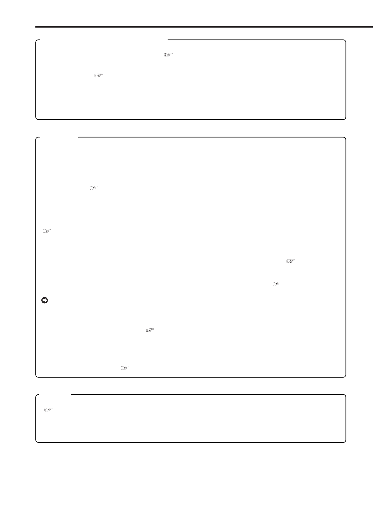
How to read this manual
• Viewing displays
(Refer to this information when operating)
Reference information concerning operation is
described.
(Caution required)
Cautionary items concerning operation are
described.
(See reference page)
Reference item and page number are indicated.
INFORMATION
Other reference information is described.
• Finding desired information
There is an index on the each right page of this
manual. There is also “Contents” at the beginning
of this manual. In addition, reference pages are
indicated throughout this manual.
• Troubleshooting
Read Troubleshooting (pages 89,90) for possible
remedies to the problem.
(Reference)
Communications by Web Browser .................. 81-86
Communications by Web Browser ............................... 81-86
The personal computer product requirements ............ 81
Connections ................................................................ 81
AUTHENTICATION................................................ 81,82
Welcome ................................................................ 82-86
Live monitor ...................................................... 82,83
Playback ........................................................... 83,84
Time Search ........................................................... 84
Alarm Search ......................................................... 84
Index Search .......................................................... 84
User maintenance ............................................. 84,85
Log out ................................................................... 85
Change log in user ............................................ 85,86
Recording time table......................................... 87,88
Continuous recording time table .................................. 87,88
HDD continuous recording time (for 250GB drive) ....... 87
Without Audio recording ......................................... 87
With Audio recording .............................................. 87
Compact Flash Card continuous
recording time (for 64MB) ...................... 88
Without Audio recording ......................................... 88
With Audio recording .............................................. 88
•••••••••••••••••••••••••••••••••••••••••••••••••••••••••••••••••••••••••••••••••••••••••••••••••••••••••••••••••••••••••••••••
Beginning
11
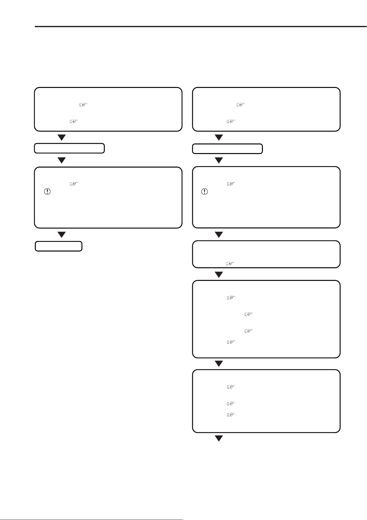
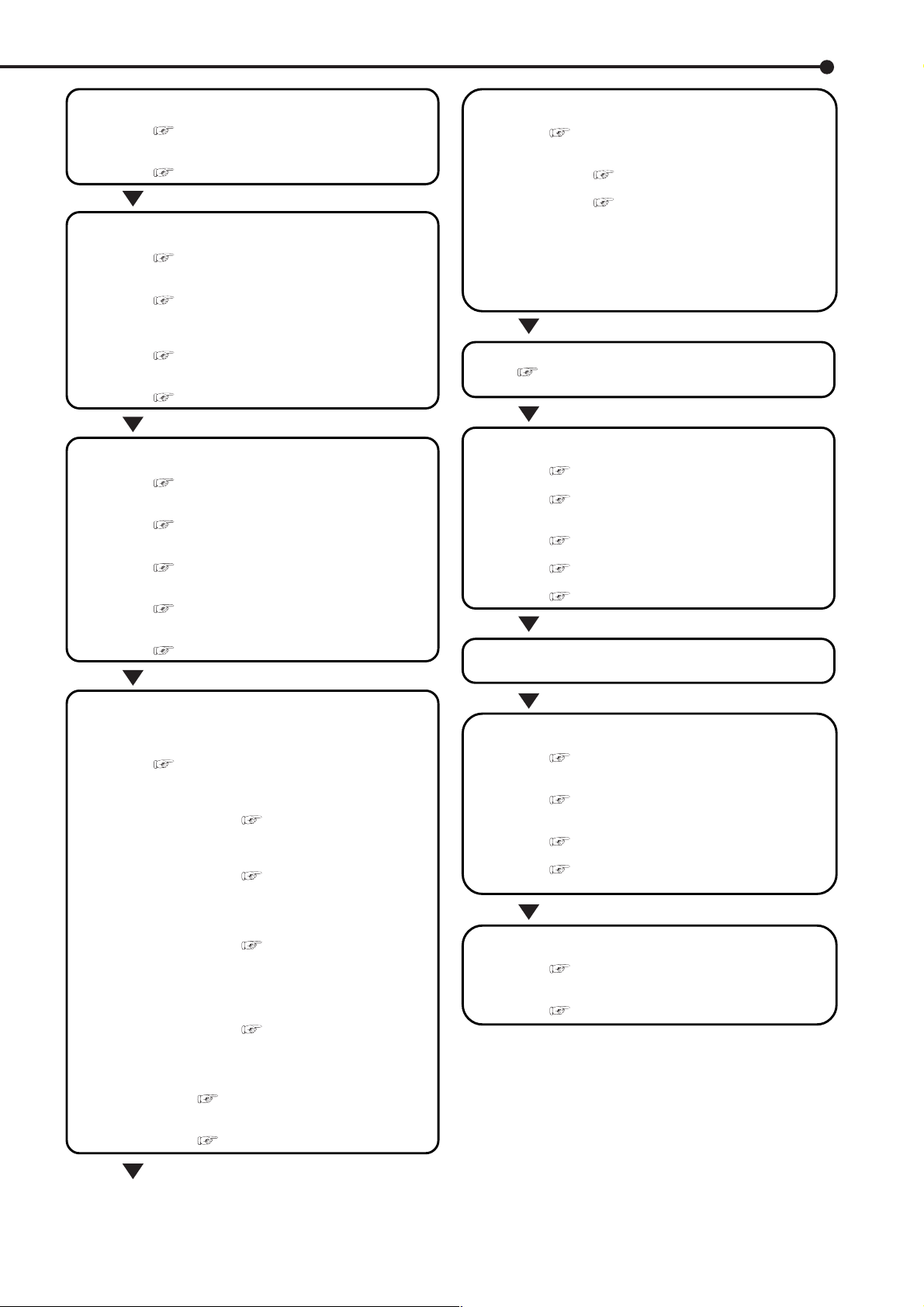
Flowchart
■ Flowchart for connection and settings
Installation example :
This is an example operational flowchart of the following : making connections at the rear of the terminal ; setting
HDD mode to PARTITION ; making default settings ; making an Alarm recording with Timer mode ; searching
recorded data with ALARM LIST SEARCH ; using playback, and copying to a Compact Flash Card.
Connection to the terminals on the back
• Connection to the terminals on the back.
See “■ Connecting to CCTV camera,
monitor, sensor”, page 19.
• Connection to the alarm recording.
See “■ Alarm Recording Connection”,
page 20 and “■ Rear View” , pages 17,18.
The unit is booted
AUTO SET UP
• Setting the auto set up.
See “■ AUTO SET UP”, pages 21,22.
Only when the unit is turned on for the first time, the
<AUTO SET UP> screen is displayed automatically. It is not
automatically displayed after next time.
Selecting the “YES” in “PERFORM AUTO SET
UP?” setting.
Recording
Connection to the terminals on the back
• Connection to the terminals on the back.
• Connection to the alarm recording.
See “■ Connecting to CCTV camera,
monitor, sensor”, page 19.
See “■ Alarm Recording Connection”,
page 20 and “■ Rear View” , pages 17,18.
The unit is booted
AUTO SET UP
• Setting the auto set up.
Only when the unit is turned on for the first time, the
<AUTO SET UP> screen is displayed automatically. It is not
automatically displayed after next time.
See “■ AUTO SET UP”, pages 21,22.
Selecting the “NO” in “PERFORM AUTO SET
UP?” setting.
Making the HDD REC SETTING
• Setting the PARTITION. “♦ PARTITION/PARTITION SIZE”
default settings “NORMAL”
See “♦ PARTITION/PARTITION SIZE”, page 79.
} }
} “PARTITION”.
} }
Changing the initial menu settings
• Setting the present time and screen display.
• Setting the audio recording.
See “<TIME DATE/DISPLAY SETTINGS>”,
pages 36-38.
• Setting the present time.
See “♦ TIME DATE ADJUST”, pages
24,25.
• Setting the display mode.
See “■ DISPLAY MODE”, page 36.
See “■ AUDIO RECORDING”, page 52 and
“■ Continuous recording time table”, pages
87,88.
Setting the HDD (hard disk drive) mode
• Setting the repeat recording.
REPEAT REC SUB”, page 51.
• Setting the remain HDD capacity.
• Setting the call out.
See “♦ HDD REPEAT REC MAIN/HDD
See “♦ REMAIN HDD”, page 54.
See “• HDD MAIN REMAIN/HDD SUB
REMAIN”, pages 54,55 and “• HDD MAIN FULL/
HDD SUB FULL”, page 55.
12
•••••••••••••••••••••••••••••••••••••••••••••••••••••••••••••••••••••••••••••••••••••••••••••••••••••••••••••••••••••••••••••••••••••••••••
Changing the multiplexer function
• Changing the split4 , split9 screen settings.
See “■ SPLIT4 SCREEN SETTING”, page 41,
“■ SPLIT9 SCREEN SETTING”, pages 41,42.
• Changing the sequence setting.
See “■ SEQUENCE SETTING”, page 42.
Setting other various functions
• Changing the display mode.
See “■ CLOCK LOCATION SETTING”, page
36 and “■ DUPLEX MODE DISPLAY”, page 38.
• Setting the camera title/memo.
See “■ CAMERA TITLE/MEMO SETTING”,
pages 36,37 and “■ CAMERA DISPLAY”, page
36.
• Setting to output signals of the unit status.
See “♦ MODE OUT 1 ~ MODE OUT 5”, page
53.
• Setting the buzzer.
See “♦ BUZZER”, pages 53,54.
Setting the timer recording (continued)
• Setting the timer program mode.
See “<TIMER PROGRAM SETTINGS>”,
pages 48-50.
• Setting the holiday.
See “■ HOLIDAY SETTING”, page 50.
• Selecting the timer program.
See “♦ Structure of the <TIMER
PROGRAM> screen”, pages 48,49.
• Setting the timer recording.
• Selecting the day.
• Selecting the start time.
• Selecting the end time.
• Selecting the recording mode.
• Selecting the motion detection mode.
Timer recording is executed/completed
See “■ Warnings and their appropriate
countermeasures”, pages 91,92.
Setting the motion detection
• Selecting the camera number.
See “■ SELECTION CAMERA NUMBER”,
page 43.
• Setting the active/inactive of detection function.
See “■ Recording mode settings for normal
recording and alarm recording”, pages 45,46.
• Setting the detection areas.
See “■ DETECTION MASK SETTING”, page
43.
• Setting the sensitivity.
See “■ SENSITIVITY”, page 44.
• Setting the minimum number of dots for starting the
motion detection operation.
See “■ MOTION THRESHOLD”, page 44.
Setting the timer recording
Setting the recording
• Selecting the normal & alarm recording or pre-alarm
recording.
See “■ Recording mode settings A ~ D for
normal recording/alarm recording”, page 50.
• Setting the recording mode.
• Setting the motion detection recording.
See “■ MOTION DET REC”,
page 50.
• Selecting the camera selection during
the alarm recording.
See “■ Recording mode
settings for normal recording and
alarm recording”, pages 45,46.
• Setting the interval/picture grade for
normal recording.
See “♦ Setting the recording
interval and recording picture
quality for normal recording”,
pages 26,27.
• Setting the interval/picture grade for
alarm recording.
See “♦ Setting the recording
interval and recording picture
quality for normal recording”,
pages 26,27.
• Setting the duration of alarm recording.
See “■ ALARM REC DURATION”,
page 50.
• Setting the duration of pre-alarm recording.
See “■ PRE ALARM REC”, page 47.
Searching the recorded data
• Setting the device of searching.
See “♦ PLAYBACK DEVICE”, page 71.
• Selecting the camera number of searching.
See “♦ SELECTION CAMERA NUMBER”,
page 71.
• Selecting the search mode.
See “♦ SEARCH TYPE”, page 71.
• Setting the alarm list search.
See “■ ALARM LIST SEARCH”, pages 74,75.
• Setting the search time and date of alarm list.
See “♦ DATE/TIME”, page 71.
The search is completed/The search result
is displayed
Playback the search result
• Selecting the camera number of playback.
See “<MPX DISPLAY SETTINGS>”, pages 39-
42.
• Selecting the sequence screen.
See “♦ SPLIT/SEQUENCE button
operations”, page 39.
• Playback
See “■ Basic playback”, pages 27,28.
• Selecting the speed of playback.
See “Various playback functions”, pages 69,
70.
Copy the data
• Inserting the Compact Flash Card.
See “■ Inserting/Ejecting Compact Flash
Card”, page 15.
• Setting the copy function.
See “Making Copy/Restore”, pages 76,77.
••••••••••••••••••••••••••••••••••••••••••••••••••••••••••••••••••••••••••••••••••••••••••••••••••••••••••••••••••••••••••••••
Flowchart
13

•
Major operations and their functions
■ Front View
OUTPUT B
10
3
56789
COM
11
1
2
ACCESS
POWER
1234
SPLIT/
SEQUENCE
ZOOM / 0
OUTPUT
A/B
DIGITAL RECORDER DX-TL910
8
9
1. POWER button
Press this button (with the MAIN switch on the rear
of this unit is set to ON), and unit will Power up (button light flashes). When the button is pressed again,
the unit will be in stand-by and the light will turn off.
When the unit is in operational transition such as
booting, the button will flash and other operations
are not accepted.
2. ACCESS indicator
Illuminates during access to hard disk drive or Compact Flash Card.
3. Camera number buttons (1 to 9)
Press the button to display the image on the monitor
from the camera connected to it’s input.
4. TIMER button
When this button is pressed, the unit is set to timer
recording/stand-by and the TIMER button lights.
When pressing this button for more than 1 second,
timer recording/stand-by is cancelled and the TIMER
button turns off.
5. REC/STOP button
When pressing this button, recording starts and the
button lights. When pressing the button for more than
1 second, the recording stops and the light turns off.
When pressing this button for more than 1 second
during alarm recording, recording stops. During timer
recording, recording will not stop even if the button
is pressed.
6. SHUTTLE ring
Used to set various menus and search functions,
adjusting the playback speed, and rewinding or forwarding the recording images.
PRE ALARM
12 16151413
4
M-DET
EMERGENCY
5
REC/STOP
TIMER
LOCK
CLEAR/
REW
6
8. SPLIT/SEQUENCE button
Press the button to display SPLIT9, SPLIT4 screen
or SEQUENCE screen setting on multiplexer
functions.
9. ZOOM button
Pressing this button twice, three and four times during
single screen display, magnifies the image by 100%,
200% and 400%. The magnification center point (X) is
displayed when the ZOOM buttons is first pressed.
Press the camera number buttons (1, 2, 3, 4) to move
the magnification location. When the ZOOM button is
kept pressed for one second or longer, the operation
of the camera number buttons and the SPLIT/SEQUENCE button switches support operation from
OUTPUT A (screen of the monitor connected to the
OUTPUT A connector to operations and VIDEO OUT
for OUTPUT B (screen of the monitor connected to
the OUTPUT B connector).
To display image of the monitor connected to OUTPUT B, set to “ON” in the setting of the “OUTPUT B
ON/OFF” of the <MPX DISPLAY SETTINGS> screen.
see page 41.
10. OUTPUT B indicator
This is not lit when the operation of the camera
number buttons and the SPLIT/SEQUENCE button
is set to OUTPUT A, and it lights with switching to
OUTPUT B.
11. COM (COMMUNICATION) indicator
Illuminates when establishing the communication with
personal computer.
12. PRE ALARM indicator
Illuminates during pre-alarm recording mode.
7
ENTER/
FF
14
7. JOG dial
Used to set various menus and search functions,
13. M-DET indicator
Illuminates when the motion detection function is on.
forwarding or rewinding the image during playback
(field-by-field).
•••••••••••••••••••••••••••••••••••••••••••••••••••••••••••••••••••••••••••••••••••••••••••••••••••••••••••••••••••••••••••••••••••••••••••
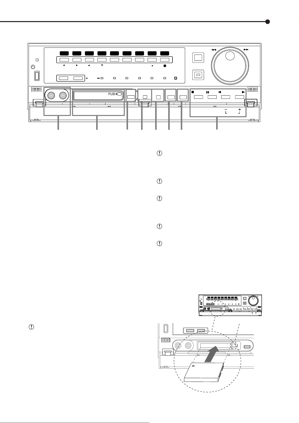
■ Front View (Inside of the door)
ACCESS
POWER
1234
SPLIT/
SEQUENCE
VIDEO OUT AUDIO OUT
17
ZOOM / 0
OUTPUT
A/B
COMPACTFLASH
18
56789
PRE ALARM
COMOUTPUT B
19 20 21 22 23 24
14. EMERGENCY indicator
Flashes during emergency recording and lights when
recording is completed.
15. LOCK indicator
Illuminates when simple lock or password lock is on.
16. LOCK button
Pressing it with a pointed object (such as a ballpoint
pen) while the MAIN switch (main power) on the rear
of the unit is on, will activate the simple lock or password lock. Also, the PASSWORD can be set on the
<PASSWORD SETTING> screen. The indicator will
light while the lock is active.
17. ANALOGUE OUT connectors
VIDEO OUT connector
Output connector for video signal (RCA pin).
AUDIO OUT connector
Output connector for audio signal (RCA pin).
COPY
M-DET
EMERGENCY
ALARM
INTERRUPT
LOCK
WARNING
RESET
SET UP
REC/STOP
SEARCH
TIMER
STOP
CLEAR/
REW
PAUSE
SHUTTLE
HOLD
REV. PLAY
Do not eject the Card when copying/restoring, copying/loading menus, or immediately after inserting the
Card. The Card or the contained data may become
damaged.
Securely insert the Compact Flash Card. Otherwise, the unit may not work properly.
Please use the Compact Flash Card which we recommend. When a non recommended Card is used,
there is a possibility that reading and writing of data
may not operate correctly.
For usable Compact Flash Card check with your
dealer of purchase.
When using a new Card, be sure to execute CFC
DATA CLEAR in the <INFORMATION/SERVICE>
screen.
<Ejecting Card>
1. Press the CFC EJECT button and eject the Card.
PLAY
MODE
PLAY
ENTER/
FF
18. COMPACT FLASH slot
2. Attach the COMPACT FLASH slot cover.
Compact Flash Card can be used for saving/loading
data and menus. When not using the slot, attach the
56789
56789
1234
1234
SPLIT/
ACCESS
POWER
VIDEO OUT AUDIO OUT
VIDEO OUT AUDIO OUT
ZOOM / 0
SPLIT/
SPLIT/
ZOOM
ZOOM / 0
SEQUENCE
SEQUENCE
OUTPUT
A/B
COMPACTFLASH
COMPACTFLASH
PRE ALARM
M-DET
COMOUTPUT B
PRE ALARM
EMERGENCY
M-DET
LOCK
EMERGENCY
LOCK
SET UP
SEARCH
COPY
SET UP
SEARCH
COPY
CFC EJECT Button
COMPACT FLASH slot cover to prevent dust from
entering within the unit.
■ Inserting/Ejecting Compact Flash Card
Before using the Card, read the cautionary notes
SEQUENCE
described in the manual included with Compact Flash
Card.
<Inserting Card>
1. Remove the COMPACT FLASH slot cover attached to the
unit.
2. Please turn down the side which contains notch in right and
left, securely insert the Card until the CFC EJECT button pops
out.
VIDEO OUT
AUDIO OUT
Compact Flash Card
•••••••••••••••••••••••••••••••••••••••••••••••••••••••••••••••••••••••••••••••••••••••••••••••••••••••••••••••••••••••••••••••
REC/STOP
REC/STOP
ENTER/
ENTER/
CLEAR/
CLEAR/
FF
FF
REW
REW
TIMER
TIMER
PLAY
REV. PLAY
STOP
PAUSE
PLAY
REV. PLAY
STOP
PAUSE
PLAY
SHUTTLE
PLAY
SHUTTLE
MODE
HOLD
MODE
HOLD
COPY
Beginning
15

•
Major operations and their functions (continued)
■ Front View (Inside of the door) (continued)
ACCESS
POWER
1234
SPLIT/
SEQUENCE
VIDEO OUT AUDIO OUT
17
ZOOM / 0
OUTPUT
A/B
COMPACTFLASH
18
56789
PRE ALARM
COMOUTPUT B
19 20 21 22 23 24
19. COPY button
Press this button to display <COPY> menu. This
button lights when performing copy operation. Copies cannot be made when a card is not in the
COMPACT FLASH slot.
20. ALARM INTERRUPT button
Pressing this button (button flashes), the unit will disable REC. from alarm signals or motion detection for
5 minutes. This allows menu changes to REC and
Alarm settings.
COPY
M-DET
EMERGENCY
ALARM
INTERRUPT
LOCK
WARNING
RESET
SET UP
SEARCH
REC/STOP
TIMER
STOP
CLEAR/
REW
PAUSE
SHUTTLE
HOLD
REV. PLAY
PLAY
MODE
PLAY
ENTER/
FF
PLAY button
Pressing this button, the unit starts playback and the
button lights.
PLAY MODE buttons
The playback speed can be changed during normal
and reverse playback by pressing PLAY(+) or REV.
PLAY( - ).
21. WARNING RESET button
This button is used to clear on-screen warning display data.
22. SET UP button
Press this button to display the <SETTINGS> menu.
23. SEARCH button
Press this button to display the <SEARCH > menu.
24. OPERATION buttons
STOP button
Press to stop playback.
PAUSE / SHUTTLE HOLD button
Pressing this button during playback, the unit
switches to still frame playback and the button lights.
When pressing this button again, the unit resumes
playback and the button turns off. When pressing
this button during shuttle playback, the set playback
speed is maintained even when letting go of the
SHUTTLE ring. (SHUTTLE HOLD)
Pressing while playback is stopped will playback the
end of latest recorded portion as a still image.
REV. PLAY (REVERSE PLAY) button
Pressing this button, the unit switches to reverse playback and the button lights.
16
•••••••••••••••••••••••••••••••••••••••••••••••••••••••••••••••••••••••••••••••••••••••••••••••••••••••••••••••••••••••••••••••••••••••••••
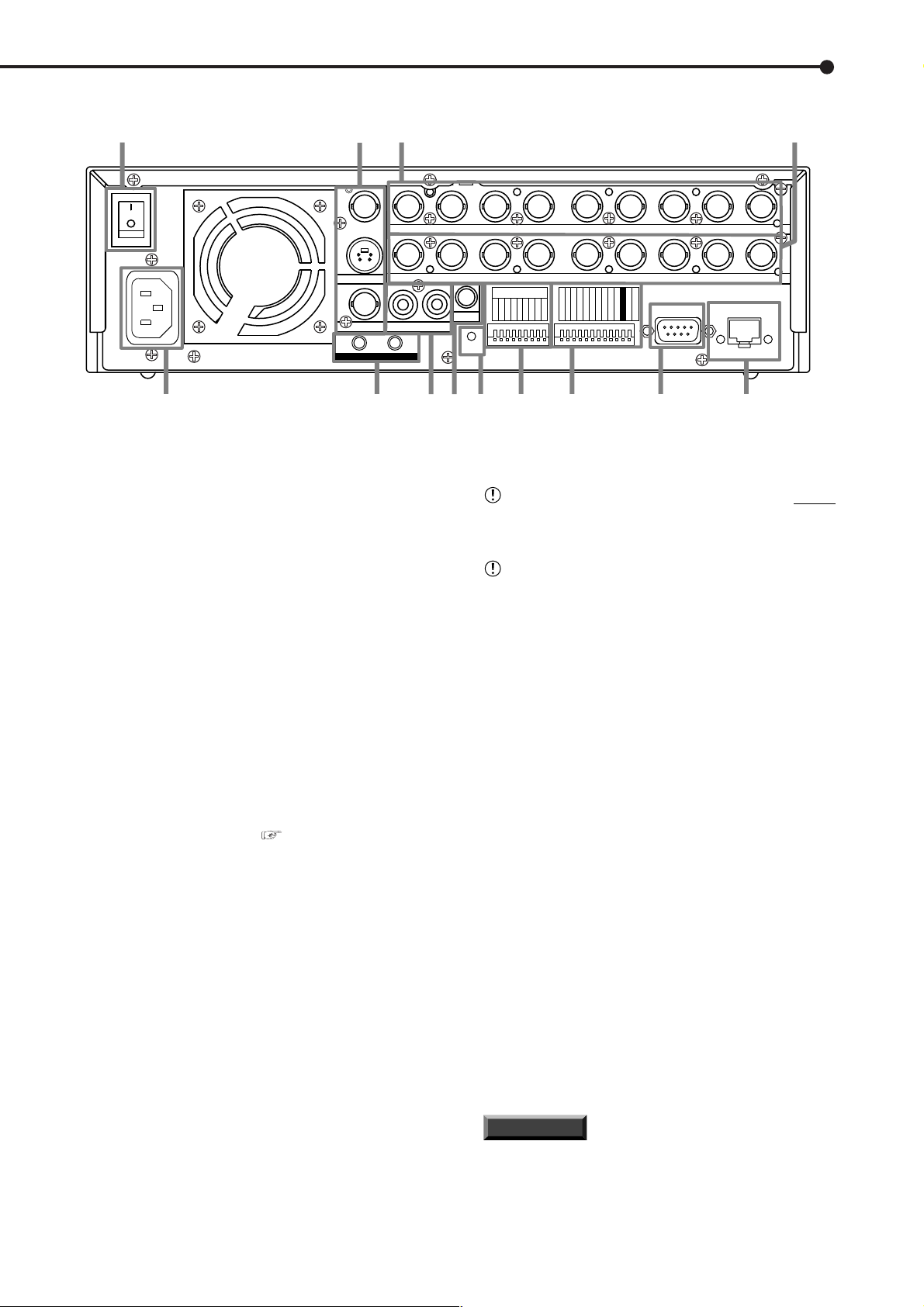
■ Rear View
1
AC IN
100-240V
ON
MAIN
OFF
~
23 4
VIDEO
Y/C
OUTPUT A
OUTPUT B
GND
5
1. MAIN switch
This is the main power switch. When using this unit,
set this switch to ON. Otherwise, the power cannot
be turned on using the POWER button on the front
of the unit.
1
234 56789
1
23 56789
1
MIC
RESET
INOUT
AUDIO
RESET
876
CAMERA IN
CAMERA OUT
4
ALARM IN
2345678
9
CLOCK ADJ
REC
EMERGENCY
MODE OUT 1
MODE OUT 2
MODE OUT 3
MODE OUT 4
MODE OUT 5
CALL OUT
109
This unit must be grounded at all times. Never
11
RS-232C
RS-232C
CALL OUT GND
MAX 350mA
DC 12V OUT
GND
12 13
connect this unit to a power outlet which does not
have a ground terminal.
Please use the AC power cord accessory.
RECEIVE
LAN
SEND
2. VIDEO OUT connectors
OUTPUT A VIDEO connector
Output connector for video signal for monitor A (BNC
connector).
OUTPUT A S(Y/C) connector
Output connector for video signals that separate
brightness signals and color signals for higher picture quality. Simultaneous output along with OUTPUT A VIDEO is also possible.
OUTPUT B connector
Output connector for video signal for monitor B for
live image display only. ( see page 41). To display the image, set “OUTPUT B ON/OFF” on the
<MPX DISPLAY SETTINGS> screen to “ON”. The
playback image cannot be put out to the OUTPUT B
connector.
3. CAMERA IN connectors
Input connector for signal of camera (BNC connector).
4. CAMERA OUT connectors
Loop through output is supported for each input camera. Each output is automatically self terminated if
not used.
5. AC power socket
This socket connects to the power cord. Earth terminal is for safety. Use the 100 ~ 240V plug with
earth for the power of this unit.
6. GND terminals
It is the common GND terminal.
7. AUDIO connectors
AUDIO IN connector
Input connector for audio signal (RCA pin).
AUDIO OUT connector
Output connector for audio signal (RCA pin).
8. MIC jack
Input connector for microphone (600 ohm impedance). Use of MIC connector for audio recording has
priority over AUDIO IN connector.
9. RESET button
Pressing this button resets the unit and the power
turns off. In this case, video data, menu settings and
the current time are kept.
10. ALARM IN terminals
Input terminal for alarm signal.
11. I/O terminals
CLOCK ADJ terminal
Input terminal to set the present time. Time display is
adjusted to the nearest hour (00 minutes 00 seconds)
when this terminal receives the CLOCK ADJ signal.
INFORMATION
The on-screen clock can be reset to the nearest hour,
by applying a signal to the CLOCK ADJ terminal. For
example, if the current time is 11:29:59, it will be reset
to 11:00:00, and if the current time is 11:30:00, it will be
reset to 12:00:00.
•••••••••••••••••••••••••••••••••••••••••••••••••••••••••••••••••••••••••••••••••••••••••••••••••••••••••••••••••••••••••••••••
Beginning
17

Major operations and their functions (continued)
■ Rear View (continued)
1
AC IN
100-240V
ON
MAIN
OFF
~
23 4
VIDEO
Y/C
OUTPUT A
OUTPUT B
1
1
AUDIO
GND
5
REC terminal
Input terminal to start recording. Not available during timer recording.
EMERGENCY terminal
Input terminal initiating immediate shift to EMERGENCY recording mode.
ALARM IN
2345678
109
CAMERA IN
CAMERA OUT
4
9
CLOCK ADJ
REC
11
EMERGENCY
MODE OUT 1
MODE OUT 2
MODE OUT 3
MODE OUT 4
MODE OUT 5
CALL OUT
CALL OUT GND
RS-232C
RS-232C
MAX 350mA
DC 12V OUT
GND
12 13
RECEIVE
LAN
SEND
234 56789
23 56789
1
MIC
RESET
INOUT
RESET
876
MODE OUT 1 ~ MODE OUT 5 terminals
Output terminal to indicate the unit’s current mode.
Select the unit’s condition by MODE OUT 1 ~ MODE
OUT 5 setting in the <REAR TERMINAL SETTINGS>
menu.
CALL OUT terminal / CALL OUT GND terminals
This is the ISOLATION output terminal. Information
that can be transmitted externally consists of CALL
OUT settings made on the <REAR TERMINAL SETTINGS> menu screen as well as fixed output settings.
DC 12V OUT terminal
Will only output when the MAIN switch is ON. The
maximum electric current is 350mA.
12. RS-232C connector
This connector is used to connect to host device with
RS-232C connector. This unit can be controlled (no
video transmission) by another device through this
connector.
13. LAN connector
Use a 10BASE-T cable to connect to the LAN terminal. Please use the cable adapted to 10BASE-T.
DUPLEX MODE is HALF DUPLEX.
18
RECEIVE indicator
Illuminates when the unit is receiving a signal.
SEND indicator
Illuminates when the unit is transmitting a signal.
••••••••••••••••••••••••••••••••••••••••••••••••••••••••••••••••••••••••••••••••••••••••••••••••••••••••••••••••••••
Beginning
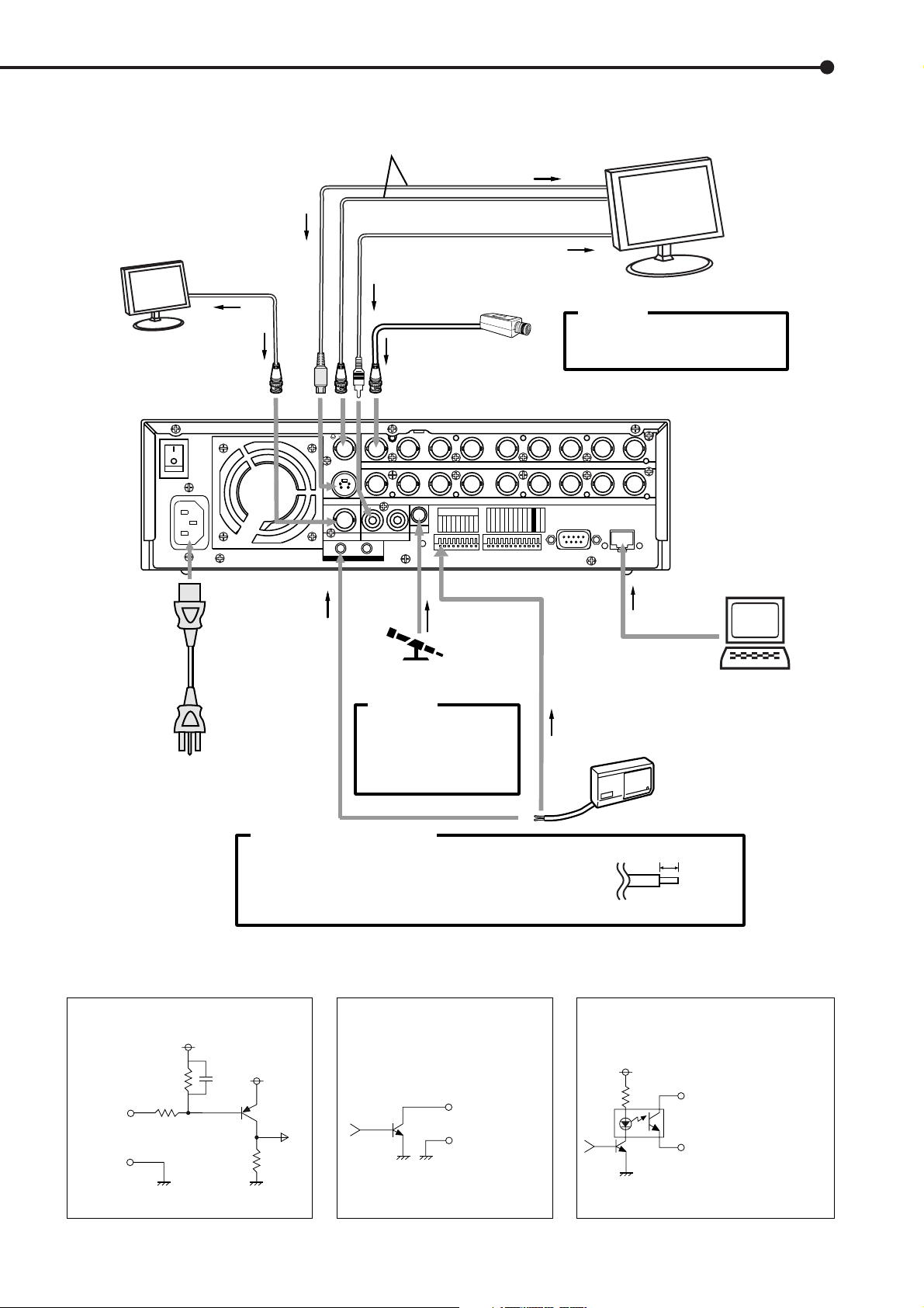
Connections
<Interface circuit inside the unit>
CALL OUT terminal
CALL OUT GND terminal
CALL OUT Output terminal
• Output Circuit
■ Connecting to CCTV camera, monitor, sensor
To OUTPUT A VIDEO or
OUTPUT A S(Y/C) connector
VIDEO MONITOR
(Only for the live image)
To OUTPUT B
connector
ON
MAIN
OFF
AC IN
~
100-240V
To VIDEO IN
connector
One of either codes
should be connected.
To AUDIO OUT
connector
To CAMERA IN 1 connector
1
234 56789
1
23 56789
MIC
RESET
INOUT
AUDIO
RESET
Y/C
OUTPUT A
OUTPUT B
VIDEO
GND
To VIDEO IN or
S(Y/C) IN connector
To AUDIO IN connector
CAMERA #1
Up to 9 cameras
CAMERA IN
CAMERA OUT
4
ALARM IN
1
2345678
9
CLOCK ADJ
REC
EMERGENCY
MODE OUT 1
MODE OUT 2
MODE OUT 3
MODE OUT 4
MODE OUT 5
CALL OUT
CALL OUT GND
MAX 350mA
DC 12V OUT
GND
MONITOR
CAUTION
Connecting a coaxial transmission
camera wrong may damage the input
terminal. Be careful.
RECEIVE
LAN
SEND
RS-232C
RS-232C
POWER
CORD
EMERGENCY/ALARM IN/REC/
CLOCK ADJ Input terminal
• Input Circuit
10kΩ
Input
terminal
22kΩ
GND
<Interface circuit inside the unit>
5V
To GND
terminal
To MIC jack
MICROPHONE
CAUTION
When a microphone is
connected to the MIC jack,
the MIC jack will be given
priority over the AUDIO IN
connector.
Processing the connecting line
Connection on the ALARM IN terminals and the I/O terminals
Compatible power lines ø0.32 ~ ø0.65 mm (AWG 28 ~ 22)
Cut the designated area from the electric wire’s outer covering
(vinyl portion).
MODE OUT 1 - 5 Output terminal
• Output Circuit
0.047µF
5V
Output terminal
GND terminal
4.7kΩ
<Interface circuit inside the unit>
To LAN
connector
HALF DUPLEX MODE
To ALARM IN terminal
corresponds to the
CAMERA #.
SENSOR #1
5~7mm
••••••••••••••••••••••••••••••••••••••••••••••••••••••••••••••••••••••••••••••••••••••••••••••••••••••••••••••••••••••••••
Connections
19

Connections
(continued)
■ Alarm Recording Connection
Example : The diagram below shows an example of con-
nection for alarm signals corresponding to camera
number 1. (In the case of ALARM SETTING of default
setting.)
ALARM IN
1
OUTPUT B
AUDIO
MIC
RESET
INOUT
2345678
9
CLOCK ADJ
REC
EMERGENCY
MODE OUT 1
MODE OUT 2
MODE OUT 3
MODE OUT 4
MODE OUT 5
CALL OUT
CALL OUT GND
MAX 350mA
DC 12V OUT
GND
GND
RESET
ALARM SWITCH
■ Connecting with analog video recorder
This unit is equipped with video output (RCA) and audio
output (RCA) connectors on the front and OUTPUT A S(Y/
C), OUTPUT A VIDEO (BNC) and AUDIO OUT (RCA) connectors on the rear. Video signals can be simultaneously
outputted from the video output connector on the front and
the OUTPUT A VIDEO/S(Y/C) connector on the rear. In
the same manner, audio signals can be outputted in simultaneously from the audio output connector on the front and
AUDIO OUT connector on the rear. By connecting an analog video recorder to these terminals, recorded contents
can be copied.
Make sure to turn off this unit when connecting with
peripheral recording devices.
20
•••••••••••••••••••••••••••••••••••••••••••••••••••••••••••••••••••••••••••••••••••••••••••••••••••••••••••••••••
Connections
AUTO SET UP
■ AUTO SET UP
AUTO SET UP is displayed, when this unit is turned on for
the first time.
Only when the unit is turned on for the first time,
the AUTO SET UP screen is displayed automatically.
1. Connect all devices (cameras and the monitors), turn on
the MAIN switch on the rear of the unit and wait until the
ACCESS indicator is turned off, then press the POWER button
on the front.
• The <TIME DATE ADJUST> screen appears.
• The date/time is set in this screen.
<CAMERA CHECK>
>>
EXECUTE
CHECK CAMERA CONNECTION AND
IMAGE BEFORE EXECUTE
SHUTTLE>>:EXECUTE
Beware while setting the AUTO SET UP, the menu
screen can not be exited.
<TIME DATE ADJUST>
>>
DAYLIGHT SAVING OFF
MONTH 01
DAY 01
YEAR 2004
TIME 00:00:00
APPLY
EXECUTE
JOG :SELECT
SHUTTLE>>:EXECUTE
POWER button operation will not be accepted while
the ACCESS indicator is flashing. Press the POWER
button after the indicator turns off.
2. Set the desired setting in this screen referring to “
DAYLIGHT SAVING/DAYLIGHT SETTING ( see page 24)”,
“♦ TIME DATE ADJUST ( see pages 24,25)”.
By turning the JOG dial to the cursor to “APPLY”
and turn the SHUTTLE ring clockwise, “00:00:00” of
“TIME” will start after the moment of turning the SHUTTLE ring.
3. Turn the JOG dial to move the cursor to “EXECUTE”, and
turn the SHUTTLE ring clockwise.
• “PERFORM AUTO SET UP?” is displayed on the screen.
PERFORM AUTO SET UP?
>>
YES
NO
5. Turn the SHUTTLE ring clockwise.
• The <AUTO RECORD SETTING> screen appears.
• The period to record can be set.
• Settings of AUTO RECORD SETTING ( default : “24H” )
“24H”, “48H”, “72H”, “96H”, “120H”, “144H”, “1WEEK”,
“2WEEK”, “3WEEK”, “1MONTH”, “2MONTH”, “3MONTH”,
“4MONTH”, “5MONTH”, “6MONTH”, “1YEAR”
<AUTO RECORD SETTING>
>>
RECORDING CYCLE 24H
EXECUTE
♦
JOG :SELECT
SHUTTLE>>:EXECUTE
6. Turn the SHUTTLE ring clockwise.
• The background of the setting changes to red and flashes.
7. Turn the JOG dial to display the desire setting and turn the
SHUTTLE ring clockwise.
• The setting is confirmed and flashing stop.
8. Turn the JOG dial to move the cursor to “EXECUTE”, and
turn the SHUTTLE ring clockwise.
• The <RECORD SETTING> screen appears.
• The recording interval and recording picture quality of
normal recording and alarm recording corresponding to each
camera numbers can be set in this screen.
Note: Any changes to REC. settings will affect length of record
set.
SHUTTLE>>:EXECUTE
4-1. (If you do not want to execute AUTO SET UP • • • )
Select “NO” by turning the JOG dial and turn the SHUTTLE
ring clockwise.
• “SETTING UP...” is displayed on the screen, and the unit
starts-up.
4-2. (When execute AUTO SET UP • • • )
Select “YES” by turning the JOG dial and turn the SHUTTLE
ring clockwise.
• The <CAMERA CHECK> screen appears.
• The cameras connected and the video condition can be
confirmed in this screen.
••••••••••••••••••••••••••••••••••••••••••••••••••••••••••••••••••••••••••••••••••••••••••••••••••••••••••••••
AUTO SET UP
21
AUTO SET UP
(continued)
/ Initial settings
The <RECORD SETTING> screen consists of 2
pages. The second page is displayed when turning the
JOG dial to move the cursor to “NEXT PAGE”, and turn
the SHUTTLE ring clockwise.
<RECORD SETTING> 1/2
Camera selection during alarm recording
<RECORD SETTING> ALARM CH
NO PPS GRADE A-PPS A-GRADE
>>
15P SUPER 15P SUPER
1
------ SUPER ------ SUPER
2
------ SUPER ------ SUPER
3
4
15P SUPER 15P SUPER
------ SUPER ------ SUPER
5
<ESTD REC> D H M
NEXT PAGE
<RECORD SETTING> 2/2
<RECORD SETTING>
NO PPS GRADE A-PPS A-GRADE
6
>>
------ SUPER ------ SUPER
7
15P SUPER 15P SUPER
8
------ SUPER ------ SUPER
9
------ SUPER ------ SUPER
<ESTD REC> D H M
PRESS POWER BUTTON TO EXIT
POWER button operation will not be accepted while
the ACCESS indicator is flashing. Press the POWER
button after the indicator turns off.
2. Select “INITIALIZATION” by turning the JOG dial, and turn
the SHUTTLE ring clockwise.
• The setting is made, and the display returns to normal after
initialization.
Settings are not confirmed unless you perform
“INITIALIZATION”.
Performing “INITIALIZATION” initializes all data on
the HDD. It deletes the complete ALARM LIST, and
the next entry is registered from 00001.
Select “POWER OFF” to abort initialization.
According to the number of the cameras connected
and the value of “RECORDING CYCLE”, the most suitable setting of the “PPS”, “A-PPS”, “GRADE” and “A-
GRADE” are set automatically.
9. When the setting is complete, press the POWER button.
• “SETTING UP...” is displayed on the screen, and the unit
starts-up.
To execute AUTO SET UP again, press and hold
the camera number button 1 and press the POWER
button, when the MAIN switch is set to ON and the
POWER button is set to OFF. The <CAMERA CHECK>
screen appears. However all menu of record setting
will be reset.
■ INITIALIZATION
Please perform initialization, when a <INITIALIZATION>
setup is changed.
<INITIALIZATION>
>>
HDD SETTING NORMAL
POWER OFF
INITIALIZATION
22
ALL DATA WILL BE ERASED
WHEN PROCEED INITIALIZATION
1. Turn ON the MAIN switch on the rear of the unit, and wait
until the ACCESS indicator goes off. Hold down the REC/STOP
button, and press the POWER button on the front of the unit.
• The unit starts-up, and the <INITIALIZATION> screen is
appears.
••••••••••••••••••••••••••••••••••••••••••••••••••••••••••••••••••••••••••••••••••••••••••
AUTO SET UP / Initial settings
Basic Operations
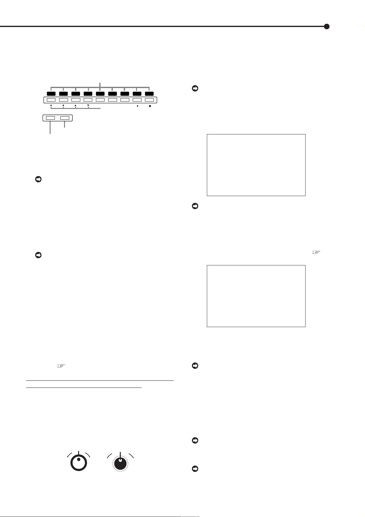
■ Multiplexer functions
Buttons on the front of the unit can be used to perform
some of the multiplexer functions.
♦ Multiplexer buttons
1 Camera number buttons (1 to 9)
1234
SPLIT/
ZOOM / 0
SEQUENCE
3 ZOOM button
2 SPLIT/SEQUENCE button
56789
MOVE button
1. Camera number buttons (1 to 9)
Video images of cameras connected to CAMERA IN terminals 1 to 9 on the rear of the unit are displayed.
By pressing a camera number button, video images can be displayed even if the camera is not set
for recording.
2. SPLIT/SEQUENCE button
The screen switches in order of SPLIT9 SCREEN
SETTING, 3 types of SPLIT4 SCREEN SETTING (a, b and
c), SPLIT4 SEQUENTIAL and SINGLE SEQUENTIAL set
in the <MPX DISPLAY SETTINGS> screen (SEQUENTIAL
display is skipped during playback).
Pressing the ZOOM button for more than 1
second on the front of this unit will switch the operation of camera number buttons and the SPLIT/SEQUENCE button to the screen of the monitor connected to the OUTPUT B connector. Pressing the
ZOOM button for more than 1 second again can
switch to the screen of the monitor connected to the
OUTPUT A connector.
3. ZOOM button
When this button is pressed during single screen display,
magnification 100% screen appears and the magnification
centre point (X) is displayed at the centre. Pressing the
button again will switch the magnification to 200% and then
400%. By pressing the MOVE buttons, the magnified screen
can be moved vertically/horizontally with the centre point
as the axis (
see “ZOOM button operations”, page 39).
When the ZOOM button is pressed, camera number
buttons 1 to 4 move the (X) on the screen.
■ Menu settings
The operational conditions of this unit can be set in the
menu screens. The JOG/SHUTTLE is used to navigate and
to make changes in the MENU SETTINGS. Use the JOG
to move up/down/across and to make a change and use
the SHUTTLE to select and accept a change and to go to
the next or previous menu.
SHUTTLE ring
JOG dial
Example : Set DISPLAY MODE to “3” ( default : “1” ).
1. Set the MAIN switch on the rear of the unit to ON. Press
the POWER button on the front after the ACCESS indicator
turns off.
• “SETTING UP...” appears on the screen and the unit is
booted.
POWER button operation will not be accepted
while the ACCESS indicator is flashing. Press the
POWER button after the indicator turns off.
2. After boot-up, press the SET UP button inside the door on
the front of the unit.
• The <SETTINGS> screen appears.
<SETTINGS>
>>
TIME DATE/DISPLAY SETTINGS
MPX DISPLAY SETTINGS
MOTION DETECTION SETTINGS
RECORD SETTINGS
TIMER PROGRAM SETTINGS
INITIAL SET UP/INFORMATION
QUICK SETTINGS
MEMO:
When the SET UP button is pressed and the
menu screen appears, the background darkens and
the displayed characters become easier to see.
3. Check to see that the cursor (>>) is positioned at “TIME
DATE/DISPLAY SETTINGS”, and then turn the SHUTTLE ring
clockwise.
• The <TIME DATE/DISPLAY SETTINGS> screen appears (
see page 36).
<TIME DATE/DISPLAY SETTINGS>
>>
TIME DATE ADJUST
DISPLAY MODE 1
CLOCK LOCATION SETTING
CAMERA DISPLAY NUMBER
CAMERA TITLE/MEMO SETTING
DUPLEX MODE DISPLAY BOTTOM
<MODE 1>
01-01-2004 00:00:00
4. Turn the JOG dial to move the cursor to “DISPLAY MODE”
and turn the SHUTTLE ring clockwise.
• The background of the “DISPLAY MODE” setting turns red
and flashes.
When turning the JOG dial clockwise, the cursor
(>>) moves down. When turning counterclockwise,
the cursor (>>) moves up.
5. Turn the JOG dial to display “3”.
• The display mode sample on the bottom of the screen
changes to <MODE 3>.
6. Turn the SHUTTLE ring clockwise.
• The setting is confirmed and flashing stops.
• To continue with other settings, repeat steps 4 and 5.
When turning the SHUTTLE ring counterclockwise
while the setting is flashing, the setting will return to
the previous setting.
To exit the screen, turn the SHUTTLE ring
counterclockwise.
••••••••••••••••••••••••••••••••••••••••••••••••••••••••••••••••••••••••••••••••••••••••••••••••••••••••••••••••••••••
Basic Operations
23

Basic Operations (continued)
<TIME DATE/DISPLAY SETTINGS>
TIME DATE ADJUST
>>
DISPLAY MODE 3
CLOCK LOCATION SETTING
CAMERA DISPLAY NUMBER
CAMERA TITLE/MEMO SETTING
DUPLEX MODE DISPLAY BOTTOM
<MODE 3>
01-01-2004 THU
00:00:00 15P 99
%
A00001
♦ To return to the normal screen from a menu screen
The procedure to return to the normal screen after completing menu screen settings using the JOG dial/SHUTTLE ring is detailed below.
1. Check to see that the setting item is no longer flashing and
the item has been changed to the desired setting.
• The setting has not been confirmed if the item is flashing.
Refer to the previous setting procedure to confirm the setting.
• To continue with other settings or to check the setting item,
turn the SHUTTLE ring counterclockwise once to return to
the previous screen.
This operation is not accepted when the setting
item is flashing.
2-1. (To return to the normal screen by moving up menu
screens one at a time • • • )
• Turn the SHUTTLE ring counterclockwise for the amount of
menu screens opened. The previous menu screen is
displayed every time the SHUTTLE ring is turned
counterclockwise.
2-2. (To directly return to the normal screen • • • )
• Press the SET UP button to clear the menu screen and return
to the normal screen.
The menu screen will not be cleared even when
pressing the SET UP button when the setting item
is flashing.
<TIME DATE ADJUST>
>>
DAYLIGHT SAVING OFF
MONTH 01
DAY 01
YEAR 2004
TIME 00:00:00
DAYLIGHT SETTING
DAY OF WEEK MONTH TIME
IN SUN 1ST APR 02:00
OUT SUN LAST OCT 03:00
JOG :SELECT
SHUTTLE>>:EXECUTE
4. Turn the JOG dial to move the cursor (>>) to “IN” and turn
the SHUTTLE ring clockwise twice.
• The “DAY” display reverses in color when the SHUTTLE
ring is turned the first time. When the ring is turned for the
second time, the display turns red and flashes.
5. Turn the JOG dial to display “MON” and turn the SHUTTLE
ring clockwise.
• The setting is confirmed and flashing stops.
6. Turn the JOG dial clockwise to move the cursor (>>) to
“WEEK”.
7. Repeat steps 4 ~ 6 to set “WEEK”, “MONTH” and “TIME”.
8. Turn the SHUTTLE ring clockwise.
• The setting is confirmed and flashing stops.
9. Turn the SHUTTLE ring counterclockwise or press the SET
UP button.
♦ TIME DATE ADJUST
Before recording is started, it is necessary to set
accurately the current date and time.
Example : Set the date/time to 10/28/2004 6:30pm
(18:30)( default : “01/01/2004 00:00:00” ).
1. Press the SET UP button to display the <SETTINGS>
screen.
♦ DAYLIGHT SAVING/DAYLIGHT SETTING
Auto daylight saving can be set (AUTO) where twice a year
the clock will either move forward or back one hour. You
can also always keep it ON or OFF as needed. Use the
JOG dial to select “AUTO” (the daylight saving function
activated.) Turn the SHUTTLE ring clockwise to enter the
selection.
In the “DAYLIGHT SETTING” setting, start/end time of the
“DAYLIGHT SAVING” function can be checked and
changed.
Example : Set the start time of the “DAYLIGHT SAVING”
function “IN” to “MON”, “LAST”, “MAR” and “01:00”.
( default : “SUN”, “1ST”, “APR”, “02:00” ).
1. Press the SET UP button to display the <SETTINGS>
screen.
2. Check to see that the cursor (>>) is positioned at “TIME
DATE/DISPLAY SETTINGS”, and then turn the SHUTTLE ring
clockwise.
• The <TIME DATE/DISPLAY SETTINGS> screen appears.
3. Check to see that the cursor is positioned at “TIME DATE
ADJUST”, and then turn the SHUTTLE ring clockwise.
• The <TIME DATE ADJUST> screen appears.
<TIME DATE ADJUST>
>>
DAYLIGHT SAVING OFF
MONTH 01
DAY 01
YEAR 2004
TIME 00:00:00
4. Turn the JOG dial to move the cursor to “MONTH” and turn
the SHUTTLE ring clockwise.
• The background of “MONTH” changes to red and flashes.
<TIME DATE ADJUST>
DAYLIGHT SAVING OFF
>>
MONTH 01
DAY 01
YEAR 2004
TIME 00:00:00
5. Turn the JOG dial to display “10” and turn the SHUTTLE
ring clockwise.
• The setting is confirmed and flashing stops.
24
••••••••••••••••••••••••••••••••••••••••••••••••••••••••••••••••••••••••••••••••••••••••••••••••••••••••••••••••••••••••••••••••••••••••••••
<TIME DATE ADJUST>
DAYLIGHT SAVING OFF
>>
MONTH 10
DAY 01
YEAR 2004
TIME 00:00:00
6. Turn the JOG dial clockwise to move the cursor (>>) to
“DAY”.
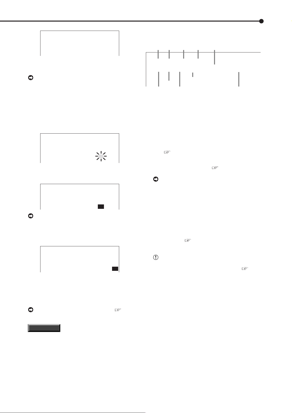
♦ Recorded capacity display function
Month
Day
01 - 01 - 2004
00 : 00 : 00 15P 99% A00001
Year
the week
THU
Day of
Recorded capacity of
the Hard Disk
When turning the JOG dial clockwise, the cursor
(>>) moves down. When turning counterclockwise,
the cursor (>>) moves up.
7. Repeat steps 4 ~ 6 to set “DAY” and “YEAR”.
8. Turn the JOG dial to move the cursor (>>) to “TIME” and
turn the SHUTTLE ring clockwise twice.
• The “TIME” display reverses in color when the SHUTTLE
ring is turned the first time. When the ring is turned for the
second time, the display turns red and flashes.
<TIME DATE ADJUST>
DAYLIGHT SAVING OFF
MONTH 10
DAY 28
YEAR 2004
TIME 00:00:00
9. Turn the JOG dial to display “18” and turn the SHUTTLE
ring clockwise.
• The setting is confirmed and flashing stops.
<TIME DATE ADJUST>
DAYLIGHT SAVING OFF
MONTH 10
DAY 28
YEAR 2004
TIME 18:00:00
The time is indicated using the 24-hour system.
10. Repeat steps 8 and 9 to set “MINUTE” and “SECOND”.
11. Turn the SHUTTLE ring clockwise.
• The setting is confirmed and flashing stops.
<TIME DATE ADJUST>
DAYLIGHT SAVING OFF
MONTH 10
DAY 28
YEAR 2004
TIME 18:30:00
12. Turn the SHUTTLE ring counterclockwise.
Playback interval
Minute
Hour
(Single screen playback only)
Second
Alarm recording number
This unit displays the used space of the specified recording device (HDD) on the screen when “REMAIN HDD” of
the <REAR TERMINAL SETTINGS> screen is set to
“MAIN”, “SUB”. The “%” indicates the ratio detected as HDD
against the total HDD capacity. The following settings are
required to enable this function.
1) Select the device and set the remaining capacity using
“REMAIN HDD” of the <REAR TERMINAL SETTINGS>
screen (
see page 54).
2) Select “3” for “DISPLAY MODE” in the <TIME DATE/
DISPLAY SETTINGS> screen (
see page 36).
During recording, the used HDD space is displayed. When recording is stopped, the display is
cleared (with the exception of when pausing recording). The HDD usage display appears again after a
few moments when recording is started once more.
■ Basic manual recording
Normal recording using manual operation is explained here.
Before starting recording, recording settings must be
checked. After checking the settings of “HDD REPEAT REC
MAIN”, “HDD REPEAT REC SUB” in the <HDD SETTINGS> screen ( see page 51), the REC mode settings are made.
Settings here are for normal recording only. For
timer recording, settings must be made on the
<TIMER PROGRAM SETTINGS> screen (
page 48).
see
♦ Present time display
When turning on the unit power, the time/date display shown
to the right appears (in the case of DISPLAY MODE 3).
For setting other display modes, see
“DISPLAY MODE” page 36.
INFORMATION
This unit uses 4 digits to display the year. The
allowed display range is 99 years between 1/1/
2001 ~ 31/12/2099. The unit is also equipped with
a function to automatically calculate leap years.
The date returns to the year 2001 after 31/12/
2099.
••••••••••••••••••••••••••••••••••••••••••••••••••••••••••••••••••••••••••••••••••••••••••••••••••••••••••••••••••••••
Basic Operations
25
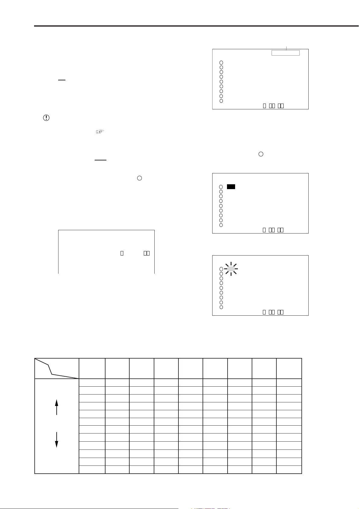
Basic Operations (continued)
♦ Setting the recording interval and recording
picture quality for normal recording
To perform normal recording, “PPS” and “GRADE” must
be set for each camera.
Setting of “PPS” ( default : “3P” )
3P”, “2P”, “1.5P”, “1.2P”, “1P”, “0.6P”, “0.4P”,
“6P”, “
“0.2P”, “0.1P”, “0.05P”, “0.025P”, “- - - - - -”
“- - - - - -” : Recording cannot be performed with
camera set to this item.
Available recording intervals will vary according
to the number of cameras operating or ALARM RECORDING settings (
see page 45). Interval dis-
plays will be according to the chart.
Setting of “GRADE” ( default : “STD” )
“SUPER”, “HIGH”, “
STD”(STANDARD), “BASIC”,
“LONG”
Example : Set “PPS” of camera number “
1
” to “0.4P” and
“GRADE” to “HIGH” for normal recording.
1. Press the SET UP button to display the <SETTINGS> screen.
2. Turn the JOG dial to move the cursor to “RECORD
SETTINGS” and turn the SHUTTLE ring clockwise.
• The <RECORD SETTINGS> screen appears.
<RECORD SETTINGS>
>>
ALARM SETTING
RECORD SETTING
ALARM REC DURATION 5S
PRE ALARM REC ( S ) S
MOTION DET REC ALARM
3. Turn the JOG dial to move the cursor to “RECORD
SETTING” and then turn the SHUTTLE ring clockwise.
• The <RECORD SETTING> screen appears.
<RECORD SETTING>
Camera selection during alarm recording
<RECORD SETTING> >>ALARM CH
NO PPS GRADE A-PPS A-GRADE
3P STD 3P STD
1
3P STD 3P STD
2
3P STD 3P STD
3
4
3P STD 3P STD
3P STD 3P STD
5
6
3P STD 3P STD
3P STD 3P STD
7
3P STD 3P STD
8
3P STD 3P STD
9
<ESTD REC> D H M
About <ESTD REC>
• The estimated recordable time is displayed as <ESTD REC>
depending on the “PPS” and “GRADE” settings. (The time
will not change when changing the alarm recording settings.)
4. Turn the JOG dial to select “ 1” , and then turn the SHUTTLE
ring clockwise.
• The “PPS” setting reverses in color.
<RECORD SETTING> ALARM CH
NO PPS GRADE A-PPS A-GRADE
3P STD 3P STD
1
3P STD 3P STD
2
3P STD 3P STD
3
4
3P STD 3P STD
3P STD 3P STD
5
6
3P STD 3P STD
3P STD 3P STD
7
3P STD 3P STD
8
3P STD 3P STD
9
<ESTD REC> D H M
5. Turn the SHUTTLE ring clockwise again.
• The background of the “PPS” setting turns red and flashes.
<RECORD SETTING> ALARM CH
NO PPS GRADE A-PPS A-GRADE
3P STD 3P STD
1
3P STD 3P STD
2
3P STD 3P STD
3
4
3P STD 3P STD
3P STD 3P STD
5
6
3P STD 3P STD
3P STD 3P STD
7
3P STD 3P STD
8
3P STD 3P STD
9
<ESTD REC> D H M
26
Relationship between the number of operational cameras and available “PPS” (pictures per second)
Number of
operational
PPS
SHORT
Recording
interval
LONG
cameras
# 1 # 2 # 3 # 4 # 5 # 6 # 7 # 8 # 9
30P
15P
10P
7.5P
6P
5P
3P
2P
1P
0.5P
0.25P
0.125P
30P
15P
10P
7.5P
6P
5P
3P
2P
1P
0.5P
0.25P
0.125P
15P
7.5P
5P
3.75P
3P
2.5P
1.5P
1P
0.5P
0.25P
0.125P
0.063P
15P
7.5P
5P
3.75P
3P
2.5P
1.5P
1P
0.5P
0.25P
0.125P
0.063P
10P
5P
3.333P
2.5P
2P
1.667P
1P
0.667P
0.333P
0.167P
0.083P
0.042P
10P
5P
3.333P
2.5P
2P
1.667P
1P
0.667P
0.333P
0.167P
0.083P
0.042P
7.5P
3.75P
2.5P
1.875P
1.5P
1.25P
0.75P
0.5P
0.25P
0.125P
0.063P
0.031P
7.5P
3.75P
2.5P
1.875P
1.5P
1.25P
0.75P
0.5P
0.25P
0.125P
0.063P
0.031P
6P
3P
2P
1.5P
1.2P
1P
0.6P
0.4P
0.2P
0.1P
0.05P
0.025P
••••••••••••••••••••••••••••••••••••••••••••••••••••••••••••••••••••••••••••••••••••••••••••••••••••••••••••••••••••••••••••••••••••••••••••
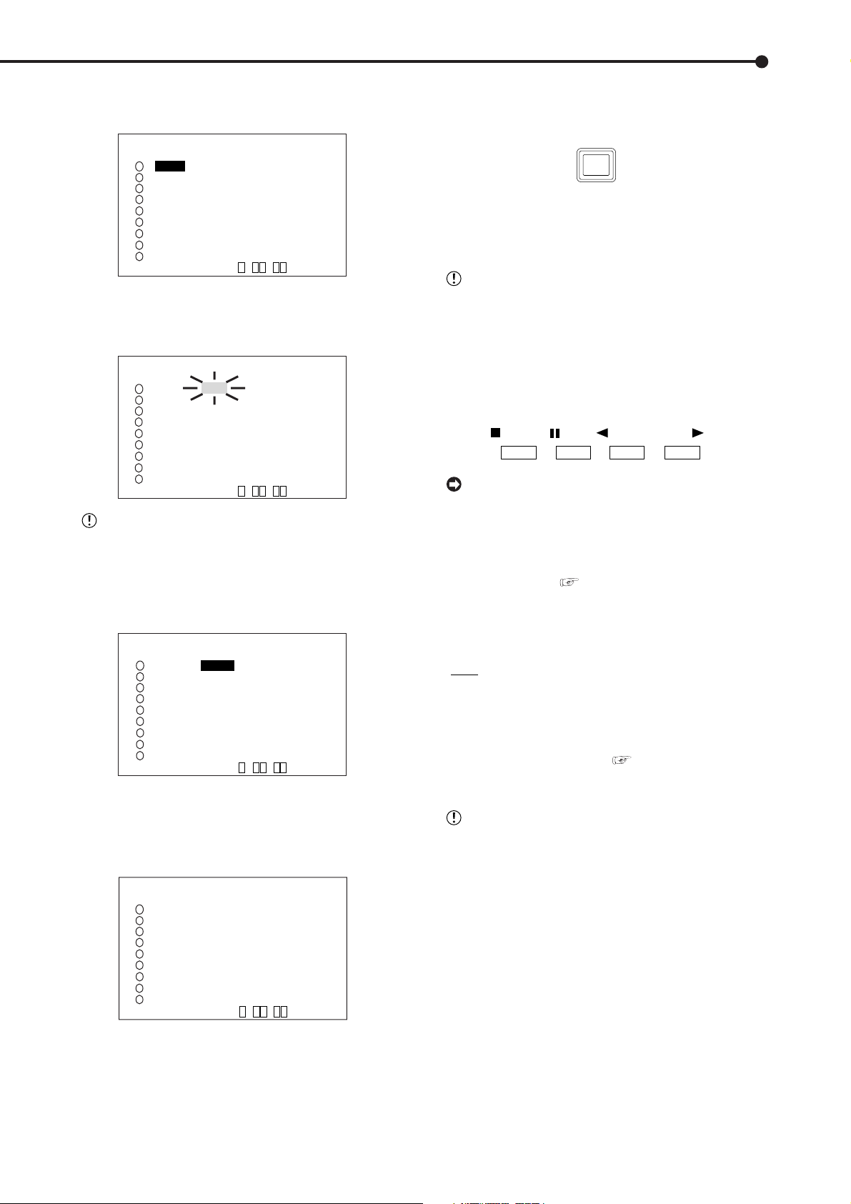
6. Turn the JOG dial to select “0.4P” and turn the SHUTTLE
ring clockwise.
• Setting is confirmed and flashing stops.
<RECORD SETTING> ALARM CH
NO PPS GRADE A-PPS A-GRADE
0.4P STD 3P STD
1
3P STD 3P STD
2
3P STD 3P STD
3
4
3P STD 3P STD
3P STD 3P STD
5
6
3P STD 3P STD
3P STD 3P STD
7
3P STD 3P STD
8
3P STD 3P STD
9
<ESTD REC> D H M
7. Turn the JOG dial clockwise to reverse display “GRADE”
and turn the SHUTTLE ring clockwise.
• The background of the “GRADE” setting turns red and
flashes.
<RECORD SETTING> ALARM CH
NO PPS GRADE A-PPS A-GRADE
0.4P STD 3P STD
1
3P STD 3P STD
2
3P STD 3P STD
3
4
3P STD 3P STD
3P STD 3P STD
5
6
3P STD 3P STD
3P STD 3P STD
7
3P STD 3P STD
8
3P STD 3P STD
9
<ESTD REC> D H M
When the setting item is flashing, the menu
screen cannot be cleared even when pressing the
SET UP button.
8. Turn the JOG dial to select “HIGH” and turn the SHUTTLE
ring clockwise.
• The setting is confirmed and flashing stops.
<RECORD SETTING> ALARM CH
NO PPS GRADE A-PPS A-GRADE
0.4P HIGH 3P STD
1
3P STD 3P STD
2
3
3P STD 3P STD
4
3P STD 3P STD
5
3P STD 3P STD
6
3P STD 3P STD
7
3P STD 3P STD
8
3P STD 3P STD
9
3P STD 3P STD
<ESTD REC> D H M
9. When the setting is complete, turn the SHUTTLE ring
counterclockwise.
• The cursor appears to the camera number on the left.
• When continuing with other camera number settings, turn
the JOG dial to move the cursor to the desired camera number
and repeat steps 4 ~ 9 to perform settings.
<RECORD SETTING> ALARM CH
NO PPS GRADE A-PPS A-GRADE
>>
0.4P HIGH 3P STD
1
3P STD 3P STD
2
3
3P STD 3P STD
4
3P STD 3P STD
5
3P STD 3P STD
6
3P STD 3P STD
7
3P STD 3P STD
8
3P STD 3P STD
9
3P STD 3P STD
<ESTD REC> D H M
12. To stop recording, press the REC/STOP button for more
than 1 second.
• Recording stops and the REC/STOP button turns off.
REC/STOP
■ Basic playback
This unit allows recorded video to be played back using
various methods. The basic playback described here is the
most common method for playback.
This unit will stop playback when a request for
acquisition of live images is communicated during
playback.
1. Press the PLAY button ( inside the front door) on the front of
the unit.
• Recorded contents of the HDD are played back.
• After turning the power on, the oldest recorded video is
played back first. Otherwise, playback resumes at the position
of the previous playback.
STOP
PAUSE
REV. PLAY
When the “HDD REPEAT PLAY” setting in the
“HDD SETTINGS” is set to “OFF”, playback is
stopped at the end of the recorded section or at the
end of the physical HDD is reached. When the “HDD
REPEAT PLAY” setting is set to “ON”, recorded video
data is played back repeatedly when the end of the
HDD is reached. (
see “HDD REPEAT PLAY”,
page 51).
2-1. (To change HDD or Compact Flash Card playback device
• • • )
• Setting ( default : “MAIN” )
“MAIN” : Select when playing back MAIN HDD contents.
“SUB” : Select when playing back SUB HDD contents.
“CFC” : Select when playing back CFC contents.
• When changing the playback device to Compact Flash Card,
press the SEARCH button twice ( see page 71) to display
the <SEARCH SELECTION> screen and select “CFC”
(Compact Flash Card) in “PLAYBACK DEVICE”.
“SUB” appears on the screen when “PARTITION”
is selected on “HDD SETTING” of the <INITIALIZATION> screen.
2-2. Press the PLAY button.
• Plays from the playback device that has been selected.
PLAY
10. Turn the SHUTTLE ring counterclockwise three times or
press the SET UP button to return to the normal screen.
11. Press the REC/STOP button.
• The REC/STOP button turns on and recording starts.
••••••••••••••••••••••••••••••••••••••••••••••••••••••••••••••••••••••••••••••••••••••••••••••••••••••••••••••••••••••
Basic Operations
27
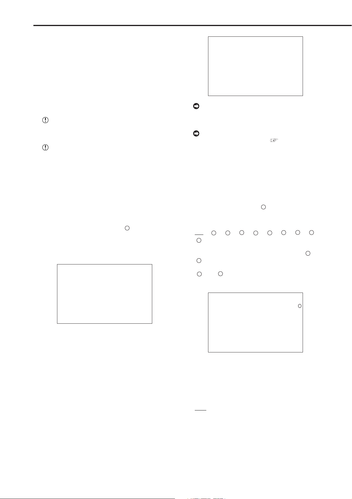
Basic Operations (continued)
3. To pause playback, press the PAUSE button.
• To resume playback, press the PAUSE button again or press
the PLAY button.
4. To stop playback, press the STOP button.
• During HDD playback/pause, playback will start the next
time from the paused position.
• During CFC playback/pause, playback will start the next time
from the oldest recorded video on the media.
■ Basic search
This SEARCH Menu is displayed when the SEARCH button is pressed.
Live and playback functions are not possible at
the same time. Because of this, a SEARCH function and Live cannot be displayed at the same time.
This unit will not search while a request for a live
images is being requested.
♦ TIME DATE SEARCH
Various search functions are available for searching the
start point of video clips. In this section, the most common
search method referred to as time/date search is explained.
With this method, searching is possible by date, hour,
minute, second and specified camera number.
Example : Search a scene recorded on the MAIN HDD
with time/date stamp of 03/03/2004 9:25:40pm
(21:25:40) using camera number “ 3 ”.
1. Press the SEARCH button to display the <TIME DATE
SEARCH> screen.
• The default setting of the search menu displayed when
pressing the SEARCH button is “TIME DATE SEARCH”.
<TIME DATE SEARCH>
>>01-01-2004 00:00:00
EXECUTE(FORWARD)
MAIN
START 02-02-2004 00:00:00
END 04-04-2004 12:30:15
PUSH SEARCH KEY FOR
SEARCH SELECTION
2. Check to see that the cursor is next to the search date and
turn the SHUTTLE ring clockwise twice.
• The display reverses in color when the SHUTTLE ring is
turned the first time. When the ring is turned for the second
time, the display turns red and flashes.
3. Turn the JOG dial to display “03” for “MONTH” and turn the
SHUTTLE ring clockwise.
• Setting is confirmed and flashing stops.
4. Turn the JOG dial to reverse display “DAY” and turn the
SHUTTLE ring clockwise.
• The background of the setting item changes to red and
flashes.
5. Turn the JOG dial to display “03” for “DAY” and turn the
SHUTTLE ring clockwise.
• Setting is confirmed and flashing stops.
<TIME DATE SEARCH>
>>
03-03-2004 21:25:40
EXECUTE(FORWARD)
MAIN
START 02-02-2004 00:00:00
END 04-04-2004 12:30:15
PUSH SEARCH KEY FOR
SEARCH SELECTION
To exit the <TIME DATE SEARCH> screen without
searching, turn the SHUTTLE ring counterclockwise
or press the SEARCH button twice.
For details concerning <SEARCH SELECTION>
for selecting search functions (
see page 71).
7. Press the SEARCH button to display the <SEARCH
SELECTION> screen.
8. Check to see that the cursor is positioned at “SELECTION
CAMERA NUMBER”, and then turn the SHUTTLE ring
clockwise.
• The background of the setting item changes to red and
flashes.
9. Turn the JOG dial to select “ 3 ” and turn the SHUTTLE
ring clockwise.
• Setting is confirmed and flashing stops.
• Setting ( default : “ALL” )
“ALL”, “ 1 ”, “ 2 ”, “ 3 ”, “ 4 ”, “ 5 ”, “ 6 ”, “ 7 ”, “ 8 ”,
“ 9 ”
“ALL” : Search is conducted for all camera number “ 1 ” ~
“ 9 ”and displays the results on SPLIT9 screen.
“ 1 ” ~ “ 9 ” : This search mode scans for matches to
search criteria in the selected camera and displays the results
on 1 screen.
<SEARCH SELECTION>
SEARCH TYPE TIME DATE
>>
SELECTION CAMERA NUMBER
PLAYBACK DEVICE MAIN
MAIN
START 02-02-2004 00:00:00
END 04-04-2004 12:30:15
3
10-1. (To change HDD or Compact Flash Card playback device
• • • )
Turn the JOG dial to select “PLAYBACK DEVICE” and turn
the SHUTTLE ring clockwise.
• The background of the setting item changes to red and
flashes. Turn the JOG dial to display the desired playback
device and confirm.
• Setting ( default : “MAIN” )
“MAIN” : Select when playing back MAIN HDD contents.
“SUB” : Select when playing back SUB HDD contents.
“CFC” : Select when playing back CFC contents.
28
6. Repeat steps 4 and 5 to set “YEAR”, “HOUR”, “MINUTE”
and “SECOND”.
••••••••••••••••••••••••••••••••••••••••••••••••••••••••••••••••••••••••••••••••••••••••••••••••••••••••••••••••••••••••••••••••••••••••••••

“SUB” appears on the screen when “PARTITION”
is selected on “HDD SETTING” of the <INITIALIZATION> screen.
10-2. (To change the search type • • • )
Turn the JOG dial to select “SEARCH TYPE” and turn the
SHUTTLE ring clockwise.
• The background of the setting item changes to red and
flashes. Turn the JOG dial to display the desired search menu
and confirm.
• Setting ( default : “TIME DATE” )
“TIME DATE”, “INDEX”, “ALARM INDEX”, “ALARM SKIP”,
“ALARM LIST”
11. When the setting is complete, turn the SHUTTLE ring
counterclockwise.
• The display returns to the <TIME DATE SEARCH> screen
and the cursor appears on the left of the search date.
12. Turn the JOG dial to select “EXECUTE(FORWARD)” and
turn the SHUTTLE ring clockwise.
• When the TIME DATE SEARCH is executed, the video of the
set date/time (or the video closest to the search) will appear
in still frame.
• The search result will appear using SPLIT9 screen when
“ALL” is selected in “SELECTION CAMERA NUMBER” of the
<SEARCH SELECTION> screen. If a camera number has been
selected individually, the still frame will be displayed in full
screen.
14. To stop playback/still frame playback, press the STOP
button.
• The display returns to the normal screen.
15. Press the SEARCH button twice to clear the <SEARCH
SELECTION> screen.
■ LANGUAGE SELECTION
With this unit, the menu screen display can be selected
from 6 languages. As “ENGLISH” is selected for the initial
setting, please perform setting according to the following
procedure if you want to select a language other than “ENGLISH”.
Setting ( default : “ENGLISH” )
ENGLISH”, “FRANCAIS”, “ESPAÑOL”
“
1. Press the SET UP button } <SETTINGS> } Select
“LANGUAGE SELECTION” in the <INITIAL SET UP/
INFORMATION> screen and display the desired setting.
<LANGUAGE SELECTION>
>>
LANGUAGE ENGLISH
When there is no recording of the set time, the
video of the closest time and date for the set cam-
era number will be displayed in still frame.
Depending on the recording condition, TIME
DATE SEARCH may not operate correctly.
To display full screen view by selecting a camera number from the SPLIT9 screen of the search
result when “ALL” is selected in the “SELECTION
CAMERA NUMBER” setting, press the SEARCH
button to clear the SEARCH menu and press the
desired camera number button. The desired video
is displayed in full screen.
Press the camera number buttons during still
image playback to call up search mode. The search
mode status may continue for several hours if the
number of a camera with a small number of recorded
images has been specified. When not required,
press the STOP button to cancel the search status.
13. To playback the searched image.
• Press either the PLAY button or the PAUSE button.
For playback, see “Various playback functions”, pages 69,70.
3
03-03-2004 21:25:40
JOG :SELECT
SHUTTLE>>:EXECUTE
2. Turn the SHUTTLE ring counterclockwise or press the SET
UP button.
PLAY
••••••••••••••••••••••••••••••••••••••••••••••••••••••••••••••••••••••••••••••••••••••••••••••••••••••••••••••••••••••
Basic Operations
29
 Loading...