

Mitsubishi Electric DX-TL4516E, DX-TL4516E(Z), DX-TL4716E Installer Manual

DIGITAL RECORDER
INSTALLERʼS MANUAL
MODEL
DX-TL4516E
DX-TL4516E(Z)
ENGLISH
OTHERS
THIS INSTRUCTION MANUAL IS IMPORTANT TO YOU. PLEASE READ IT BEFORE USING YOUR DIGITAL RECORDER.
1

Caution and care
HEAVY OBJECTS SHOULD NEVER BE PLACED ON THE UNIT (E.G., MONITOR)
NEVER TOUCH OR INSERT ANY OBJECT INSIDE THE UNIT
Touching the inside of the cabinet or inserting foreign objects of any kind through the disc loading slot or ventilation holes not
only creates a safety hazard but can also cause extensive damage.
PROTECT THE POWER CORD
Damage to the power cord may cause fi re or shock hazard. If the power cord is damaged, turn OFF the MAIN switch and
carefully unplug the cord by holding the main plug.
If this unit is moved with the power on status, the built-in HDD may be damaged. Confi rm that more than one minute have
passed since the power cord and the connecting cords were disconnected, then move this unit. Make sure to take the disc out
and close the disc loading slot.
UNPLUG THE POWER CORD DURING A LONG ABSENCE
Turn off the power and unplug the power cord during a long absence.
MAINTAIN GOOD VENTILATION
Do not obstruct the many ventilation holes on the unit. For maximum ventilation, leave some space around the unit and place
the unit on a hard level surface only, and ensure it is not covered during use. Heavy objects should never be placed on the
unit.
WHEN NOT IN USE
When not in use, always eject the disc and turn OFF the MAIN switch.
CABINET CARE
Never use petroleum-based cleaners. Clean with a soft cloth moistened with soap and water and wipe dry.
PVC cables or leads should not be left in contact with the cabinet surface for long periods.
INSTALLATION LOCATION
For excellent performance and lasting reliability install in a location that is:-
1. Well ventilated, out of direct sunlight and away from direct heat.
2. A solid vibration-free surface.
3. Free from high humidity, excessive dust and away from magnetic fi elds.
4. Please ensure that the ventilation fan located on the unit’s back panel is not blocked.
UNSUITABLE LOCATIONS
Placing the unit in the following places might shorten the product life:
• Extremely cold places, such as refrigerated warehouses and ice houses
• Places where excessive hydrogen sulfi de is likely to be generated, such as hot-springs areas
• Places or locations with salt air environment.
THIS EQUIPMENT DOES NOT PROVIDE CONNECTION FOR USED WITH OUTDOOR OR CABLE DISTRIBUTION
SYSTEMS.
NO OBJECTS FILLED WITH LIQUIDS, SUCH AS VASES, SHALL BE PLACED ON THE APPARATUS.
DO NOT PLACE HEAVY OBJECT ON THIS UNIT.
DO NOT STEP ONTO THIS UNIT.
DO NOT PLACE ANY OBJECTS IN FRONT OF THE DISC LOADING SLOT.
The unit may drop or fall by losing its balance. It may cause injury or failure of the unit.
WARNING: TO PREVENT FIRE OR SHOCK HAZARD, DO NOT EXPOSE THIS APPARATUS TO RAIN OR MOISTURE.
THIS APPARATUS MUST BE GROUNDED.
MAINS LEAD CONNECTION
The mains lead on this Unit is fi tted with a non-rewireable mains plug, incorporating a 5A fuse. If you need to replace
the fuse, use a 5A fuse approved by BSI or ASTA to BS 1362, ensuring you refi t the fuse cover. If the mains plug is not
suitable for the sockets in your home, and you require to remove the plug, remove the fuse, cut off the plug then dispose
of the plug immediately, to avoid a possible electric shock hazard. To refi t a new plug, follow these instructions; Green-
and-yellow: Earth, Blue: Neutral and Brown: Live. As the colours in the mains lead of this Unit may not correspond with the
coloured markings identifying the terminals in your plug, proceed as follows.
• The wire which is coloured green-and-yellow must be connected to the terminal in the plug which is marked by the
letter E or by the safety earth symbol
• The wire which is coloured blue must be connected to the terminal which is marked with the letter N or coloured black.
• The wire which is coloured brown must be connected to the terminal which is marked with the letter L or coloured red.
This unit complies with the requirements of the EC Directive 89/336/EEC, “EMC Directive” and 73/23/EEC, “Low Voltage
Directive”, as amended by Directive 93/68/EEC. The requirements for the susceptibility according to EN 55024 and the
requirements for interference according to EN 55022 are observed for the operation on residential areas, business, light
industrial premises and in small scale enterprises, inside as well as outside of the building. All places of operation are
characterised by their connection to the public low voltage power supply system. This unit is manufactured in accordance
with EN 60950-1.
2
or coloured green or green-and-yellow.
Note: This symbol mark is for EU countries only.
This symbol mark is according to the directive 2002/96/EC Article 10 Information for users and Annex IV.
Your MITSUBISHI ELECTRIC product is designed and manufactured with high quality materials and components which
can be recycled and reused.
This symbol means that electrical and electronic equipment, at their end-of-life, should be disposed of separately from
your household waste.
Please, dispose of this equipment at your local community waste collection/recycling centre.
In the European Union there are separate collection systems for used electrical and electronic product.
Please, help us to conserve the environment we live in!
Notice about construction of the surveillance system using this unit
• This unit can be controlled by the external devices via RS-232C terminal or LAN terminal. This unit can also be used to
control external devices via external terminal, RS-422/485 terminal, or RS-232C terminal. Owning to these functions,
this unit fl exibly applies to the high grade security system, but the whole surveillance system may be affected by the
malfunction of this unit or the external devices depending on the setting contents of this unit, the connection with the
external devices, or combination between this unit and the external devices.
• When configuring a surveillance system using this unit, it is recommended to confirm first that this unit operates
normally with the other devices connected.
• It is recommended to copy or back up the important recorded contents.
• Damages rising out of any operational error of the surveillance system or loss of the recorded data or any other
damages because of any user malfunction of this unit are not covered.
• Do not use the notifi cation function of this unit for making critical judgement nor any purpose related to human lives.
• When this unit cannot recognize the external device which is being used for recording due to the power failure,
decreased voltage, or other failures, the recording point may be moved to the internal HDD of this unit or the other
external HDD. To prevent occurrence of such problem, it is recommended to use uninterruptible power supply.
• If the power plug is disconnected or the breaker switch is turned off during recording, HDD may be damaged or
playback of recorded data may become impossible.
If the breaker switch is turned on and off everyday, set the timer recording to be performed only for the period that the
breaker is on and do not turn off the breaker during recording.
ENGLISH
There may be cases when the unit's built-in motion detection function does not operate properly due to external
condition, video input signal, or other factors.
The user will not be indemnifi ed for problems (e.g., recording failure or playback failure) that occur with either the unit or
a connected device during operation. It is recommended to back up the important recordings regularly as a precaution
against possible breakdowns and accidents.
Recordable time and product warranty
Continuous recordable time and the estimated time displayed on the menu screen indicate the continuous time of
recording operation of this unit. They indicate the period neither for product warranty nor that for reliability of used parts.
•
This unit uses a built-in HDD, which is a precision device. Handle this unit with suffi cient care.
•
Do not subject this unit to vibrations or shocks. This may cause trouble specially when the power of the unit is turned
on or when the HDD is being accessed, and suffi cient care is required.
•
Do not disconnect the power plug while the power of the unit is turned on or while recording or playing.
•
For early detection of faults, we recommend that you request inspection once a year.
The HDD and cooling fan of this unit are driving parts. For stable recording, it is recommended that both of these parts are
replaced every 30,000 hours.
(This interval is for reference purpose only and does not indicate the warranty period of the parts.)
Beginning
3

Caution and care (continued)
DISCLAIMER
In any event, Mitsubishi assumes no responsibility or reliability for the following:
1. Disassembly, repair, or alteration of this unit by user or installer.
2. Failure or breakdown in or damage to this unit resulting from misuse or careless handling by user or installer.
3. Inconvenience or damages arising out of inability to display or record pictures due to any reason or cause other than
breakdown or failure in this unit.
4. Failure in this unit due to combination with other equipment manufactured by a third party or inconvenience or
damages resulting from such failure.
5. Inconvenience, damages, or claims arising out of breakdown in this unit or loss of recorded video data due to
replacement of the built-in HDD by user or installer.
6. Inconvenience or damages arising out of breakdown in this unit or inability to display or record pictures due to natural
disaster including earthquake and storm.
7. Inconvenience, damages, or claims arising out of breakdown in this unit or loss of recorded video data due to impact
or vibration to the built-in HDD or an environmental factor such as temperature at the installation site.
8. Demand for damages or other claim of infringement of privacy if the pictures monitored or recorded by user become
public or are used for any purpose other than surveillance for whatever reason.
INSTALLATION LOCATION AND HANDLING
• Place this unit horizontally and in a stable place. If this unit is not placed correctly and used in an unstable place, the unit
may be damaged such as removal of the DVD/CD disc.
• Do not place this unit close to other electronic or magnetic equipment. This will avoid video and audio distortion.
• When a monitor and this unit are placed vertically, the pictures may be distorted or DVD/CD disc may not be ejected.
• Do not let stick your hands into the disc loading slot. You may get your hand caught in the slot and may got injured. If you
get your hand caught, do not get out of the slot by force. Contact your dealer after turning off the power and disconnecting
the plug.
DVD/CD DISC
• Do not use the disc cracked, deformed or repaired with adhesive. The disc may fl y into pieces and cause injury.
• Do not touch the playback surface when holding the disc.
• When dew condensation occurs on the disc, wipe the surface off before use.
• Dirt such as fi ngerprints or dust causes the deterioration of the picture quality and audio quality. Gently wipe the DVD/CD
disc from the center to the outside with a soft cloth.
• When the disc is very dirty, soak a soft cloth with water and screw water of it, wipe off the dirt lightly, then wipe with a dry
cloth.
• Do not use solvent such as benzine and thinner, a record cleaner, and static-stopper. They may damage the disc.
• Do not use the disc described below. They may damage the disc itself or this unit.
Discs on which a piece of paper or sticker is put, or a disc damaged.
Discs which the label is peeled or a disc with oozing.
Discs cracked, deformed, or repaired with adhesive.
• Store the disc in the specifi ed casing, avoiding the following places.
Places where it will be subjected to direct sunlight.
Places with excessive dust.
Places where it will be subjected to high temperatures or high humidity.
• DVD movie (cinema) or personal recorded picture cannot be played back on this unit. Only the pictures recorded on this
unit can be played back.
• Do not use the disc which has been used on the personal computer, failed to be copied, or stopped during copying due to
the power failure because they may cause malfunction of the unit.
• Although you can copy the data on DVD/CD with this unit and playback that data on the personal computer using the
supplied application software, not all the personal computers or DVD/CD drives are ensured for proper playback of such
data.
MAINTENANCE OF THE LENS FOR RECORDING/PLAYBACK (LASER PICKUP)
• When any dust adheres on the lens for recording/playback, the picture may be distorted or the audio may skip. Also normal
recording or playback may not work. Ask your dealer how to correct this problem.
Be careful, do not use the commercial lens cleaning disc, they may damage the lens.
PRECAUTION CONCERNING EXTERNAL DEVICE
• The various external HDDs can be connected to this unit in order to expand the memory or to use as the copy device.
However, during recording or playing back a picture at high rate, some pictures may be missed due to the slow rate of data
transfer or the slow speed of response from the external device connected. Be sure to check the operation suffi ciently in
advance.
• Do not use the power control function of the external device which uses bus power of this unit.
• The external device to be used may be unsuitable for the operation you want to set. It is recommended to consult your
dealer when using the external device.
Warning
This is a class A product. In a domestic environment this product may cause radio interference in which case the user may
be required to take adequate measures.
CLASS 1 LASER PRODUCT
4

Note
Thank you for purchasing Mitsubishi digital recorder DX-TL4516E/DX-TL4516E(Z) (hereinafter referred to as “Product”).
Before using this Product, please be sure to read the Software License Agreement on page 7 of the user's manual with
regard to the software contained in this Product (hereinafter referred to as
you are agreeing to be bound by the terms and conditions of the following Software License Agreement.
This Product contains software programs that are covered by GNU General Public License or GNU Lesser General Public
License. Such software programs are excluded from Licensed Software and not covered by the following Software License
Agreement. For the terms and conditions for use of the software programs covered by GNU General Public License or GNU
Lesser General Public License, please see “Notice about software to which GNU GPL/LGPL is applied”*.
In addition, this Product contains “Apache” and “OpenSSL (including “Original SSLeay” library).” These software programs
are also excluded from Licensed Software and not covered by the following Software License Agreement. For the terms and
conditions for use of these software programs, please see “Notice about Apache software”* and “Notice about OpenSSL
software”*.
Each of “Berkeley Database,” “agetty,” “expat,” and “zlib” contained in this Product is other open source software. These
software programs are excluded from Licensed Software and not covered by the following Software License Agreement. For
the terms and conditions for use of these software programs, please see “Notice about other open source software”*.
* The documents of “Notice about software to which GNU GPL/LGPL is applied,” “Notice about Apache software,” “Notice
about OpenSSL software,” and “Notice about other open source software” are contained (in the format of electronic
files as notice_GPL_LGPL_ja.pdf, notice_Apache_ja.pdf, notice_OpenSSL_ja.pdf, and notice_other_ja.pdf) in the
“OpenSoft_License” folder in the CD supplied with this Product.
“
Licensed Software”). By using this Product,
ENGLISH
Beginning
5

Features
DX-TL4516E/DX-TL4516E(Z) is a digital recorder that is equipped with HDD as its main memory and 16ch triplex multiplexer.
Addition to these features, this system has a very sophisticated video signal and data processing technique that provides
high quality picture, stable operation and reliability. The graphical user interface and pointing devices make the operation very
easy and comfortable in live monitoring and also in the handling of data from recording to export. The system offers excellent
performance and has features to suit many video surveillance applications.
Refresh rates of 800pps*/system
Thanks to the newly developed multiplexing circuit, every camera can be viewed at 50 pps refresh rate in all screen formats.
Triplex
User can view live and playback pictures on the same monitor in all screen multi-split layouts without disrupting recording.
Dual Multiplexer Outputs
The DX-TL4516E/DX-TL4516E(Z) has two video outputs (Output A / B), and both of the outputs can show single-screen, 4, 9,
10, 13 and 16 split-screen, Switched Cameras, Alarmed Camera in live mode and Recorded pictures. On Screen Menu are
shown only on monitor Output A. It is also possible to view playback pictures of different cameras at the same time with these
two video outputs.
Covert Camera Function
It is possible to hide pictures of selected cameras that are installed in sensitive areas and should only be viewed by authorized
personnel. It can be switched by <Multiplexer Setting>.
GUI
MENU, GUI (Graphical User Interface), guides the operators to their desired menu pages quickly. If the users need additional
information on MENU functions, just press the HELP key and instructions will appear on screen. The menu supports English,
German, French, Spanish, Italian, and Russian. Function keys on the front panel or USB mouse can operate the menu on the
DX-TL4516E/DX-TL4516E(Z).
pps* : picture per second
Recording rate up to 100 pps/system
Because of the new recording circuit and compression chip, the maximum recording speed is 100 pps in total, this means that
the system can record pictures with speed of up to 6.25 pps on all 16 channels. With this speed recorded pictures are seen by
the eye as real-time.
JPEG2000
The system uses JPEG2000 compression. JPEG2000 is the standard and ideal compression method for still pictures.
Because pictures are compressed to a user defined file size one by one, the estimated recording time calculated by the
system automatically is very accurate. Special playback search functions and transmission over network also benefi t from this
compression method. File sizes for each picture quality are minimized to improve storage effi ciency over previous models.
Individual Recording Setting
Recording speed and picture quality (picture fi le size) can be set for each camera individually, it is also possible to set alarm
recording setting in addition to normal recording setting. By adjusting the recording speed and picture quality, it is possible to
use HDD storage space effi ciently.
Audio Recording
Audio input is featured. The audio such as cash register operation and conversation with customers can be recorded clearly
together with the monitoring pictures.
Copy
User can make a copy of recorded picture data by using built in CD/DVD Drive on the DX-TL4516E/DX-TL4516E(Z). Or, also
you can copy the data to other digital media such as HDD and USB Memory through Serial Bus Interface.
6

ENGLISH
Microsoft is either registered trademarks or trademarks of Microsoft Corporation in the United States and/or other countries.
All other company and product names appearing herein are the property of their respective owners.
Beginning
7

Contents
Caution and care ............................................................ 2
Note .................................................................................. 5
Features .......................................................................... 6
Contents .......................................................................... 8
Flowchart ....................................................................... 10
Flowchart for connection and settings ..........................10
Major operations and their functions ......................... 12
Front view .....................................................................12
Front view (inside of the door) ......................................14
Loading/Ejecting a DVD or CD .....................................15
Rear view ......................................................................16
Connections .................................................................. 18
Connecting to CCTV camera, monitor, and sensor ...... 18
Alarm recording connection .......................................... 19
Clamping the cables .....................................................20
Connecting to an analogue video cassette recorder ....20
Optional items ...............................................................21
Recommended items ....................................................21
How to set the menus .................................................. 22
Setting the menus .........................................................22
Setting the menu using a mouse ............................22
Setting the menu using the front panel buttons ......22
Displaying a menu screen ....................................... 23
Closing a menu screen ...........................................23
Selecting an item ....................................................23
Inputting numbers ...................................................24
Setting parameters .................................................. 24
Symbols in the menus ..................................................25
Setup Wizard ................................................................. 26
Setup Wizard ................................................................26
Menu chart .................................................................... 28
Menu chart ....................................................................28
User Menu ..............................................................28
Setup Menu ............................................................. 30
System Menu .......................................................... 37
User Menu
Search ........................................................................... 39
Selecting the search function ........................................ 39
Select Source Device ...................................................39
Search by Time and Date ............................................. 39
Search by Alarm List ..................................................... 39
Find data storage location ............................................39
Search by Book Mark ...................................................39
Search by Motion ..........................................................40
Copy ............................................................................... 41
Copy Data to Copy 1 Drive/Set Copy 1 Drive ...............41
Copy Data to Copy 2 Drive/Set Copy 2 Drive ...............42
Copying the data of this unit to a video cassette ..........43
Playback software ......................................................... 44
Information .................................................................... 46
Information ....................................................................46
Protect Data .................................................................. 47
Protect Data ..................................................................47
PTZ Control ................................................................... 48
PTZ control using the menu .......................................... 48
PTZ control using the front panel buttons .....................48
Setup Menu
Recording ...................................................................... 49
Settings concerning normal recording and
alarm recording .............................................................49
Pre-alarm recording ................................................49
Set Recording Pattern A (Normal/Timer) to D (Timer) ..49
Alarm Input .............................................................. 51
Emergency Recording Setup ........................................52
Emergency recording ..............................................52
Long pre-alarm recording ........................................ 53
Audio Recording Setup .................................................53
Timer .............................................................................. 54
Timer .............................................................................54
Overlapped timer settings ....................................... 55
Motion Det ..................................................................... 56
Set Motion Detection Pattern A/Set Motion Detection
Pattern B .......................................................................56
System ........................................................................... 58
Time/Date Setting ......................................................... 58
Menu Language Selection ............................................ 58
Rear Terminal Setting ...................................................58
Mode Out Settings ..................................................58
Call Out Settings ..................................................... 59
Key Sound ..............................................................59
Buzzer .....................................................................59
Password Setting ..........................................................60
SIMPLE LOCK ........................................................ 60
Activating the simple lock .................................. 60
Releasing the simple lock .................................. 60
PASSWORD LOCK ................................................60
Using “Operation control” of PASSWORD LOCK
(level 1 to 3) .......................................................60
Registering the PASSWORD ..................................60
Activating the PASSWORD LOCK .......................... 61
Releasing the PASSWORD LOCK .........................61
Changing the PASSWORD ..................................... 61
Changing the lock mode from PASSWORD LOCK
to SIMPLE LOCK .................................................... 61
Multiplexer function related button operations/
operation table .............................................................. 62
Camera number button operations .........................62
SPLIT buttons operations .......................................62
SEQUENCE button operations ............................... 62
DIGITAL ZOOM button operations ..........................62
The function of the SPLIT, SEQUENCE, DIGITAL
ZOOM, and camera number buttons ......................63
Multiplexer Setting ........................................................64
Output A Settings ....................................................64
Output B Settings ....................................................65
Alarm Display Setting .............................................. 66
Covert Camera Setting ...........................................66
On Screen Display Setting ............................................ 67
On Screen Information ............................................67
Camera Title ............................................................ 67
Recorder Title .......................................................... 68
Monitor Output Adjust .............................................68
Reset to Factory Setting ...............................................68
Menu Data ..................................................................... 69
Load Menu Data ...........................................................69
Save Menu Data ........................................................... 69
8

System Menu
COM/LAN ....................................................................... 70
RS-232C Setting ...........................................................70
RS-485 Setting .............................................................70
LAN (Communication) Setting ......................................71
PTZ Setting .................................................................... 72
PTZ Camera Confi guration ...........................................72
Confi guration Check List ...............................................72
Service Info ................................................................... 73
System Log List ............................................................73
Elapsed Operating Time ............................................... 73
Disk Information ............................................................73
Restore .......................................................................... 74
Restore Data to Main HDD from Drive 1/2/
Export Drive 1/2 Confi guration ...................................... 74
Memory .......................................................................... 75
Add/Remove HDD Device ............................................75
Notes for using the external device ......................... 76
Attaching the HDD and setting the ID number ........76
The order of recording/playback when internal and
external HDDs are registered as the main device ..76
Add/Remove DVD/CD Drive .........................................76
Data Management Setting for Main Memory ................ 77
Recording Data Readout Setting .................................. 78
Data Clear ...................................................................... 79
Main Storage Memory ..................................................79
Copy 1/Copy 2 .............................................................. 79
Other convenient functions ......................................... 80
Various playback functions ........................................... 80
Playing still frames .................................................. 80
Shuttle viewing/direct shuttle viewing .....................80
Shuttle hold ............................................................. 80
Frame-by-frame playback ....................................... 80
Reverse playback ...................................................80
High-speed fast-forward/high-speed rewind ...........80
Changing playback intervals ................................... 81
Simultaneous playback during recording ................ 81
Playback the latest recorded contents .................... 81
Triplex playback ...................................................... 81
Registering the picture ..................................................82
Registering a bookmark .......................................... 82
Picture copy ............................................................82
Functions of the unit in case of power failure ...............83
Power failure compensation circuit .........................83
Power failure reset recording .................................. 83
Log function when power failure occurs while the unit
is in operation or the MAIN switch on the rear of the
unit is turned OFF ...................................................83
RESET button ...............................................................83
Operation examples ..................................................... 84
Operation example 1 ....................................................84
Operation example 2 ....................................................85
Operation example 3 ....................................................86
Operation example 4 ....................................................88
Basic operations .......................................................... 90
Basic multiplexer functions ...........................................90
Multiplexer buttons ..................................................90
Basic manual recording ................................................91
Setting the recording rate and picture grade for normal
recording .................................................................91
Basic playback ..............................................................92
Basic search .................................................................93
Search by Time and Date .......................................93
Search by Alarm List ...............................................94
Communications by Web Browser ............................. 95
Communications by Web Browser ................................ 95
The personal computer product requirements ........ 95
Connections ............................................................95
Login .............................................................................95
Main Menu .................................................................... 96
Live Monitoring ........................................................ 97
Playback .................................................................98
Time Search ...................................................... 98
Alarm List Search .............................................. 99
Image Search .................................................... 99
Confi guration Menu .................................................99
User Registration .............................................100
Recorder Title & Camera Titles .......................101
E-mail Setup ....................................................102
Access Mode Setup ........................................103
Clock Setup ..................................................... 103
Logout ...................................................................104
Change Login User ............................................... 104
Recording time table .................................................. 105
Continuous recording time table ................................. 105
Troubleshooting ......................................................... 106
Warnings and CALL OUT output ............................... 108
Warnings and their appropriate countermeasures ...... 108
Check sheet .................................................................110
Glossary ...................................................................... 126
Glossary ...................................................................... 126
Relation of recording operation to the number of
cameras and recording rate settings ..........................126
Specifi cations ............................................................. 127
How to read this manual
Viewing displays
(Refer to this information when operating):
Reference information concerning operation
(Caution required):
Cautionary items concerning operation
(See reference page):
Reference item and page number
Finding desired information
There is a “Contents” at the beginning of this manual. In
addition, reference pages are indicated throughout this
manual.
Troubleshooting
Read Troubleshooting (pages 106,107) for possible
remedies to the problem.
Menu settings
See Check list (pages 110-125) for available setting
parameters for each menu.
Beginning
ENGLISH
9

Flowchart
Flowchart for connection and settings
This is a fl owchart of connection and settings for making an alarm recording with timer recording and then search, playback,
and copy the recorded data.
Connections
• Connections for camera, monitor, and sensor.
See “ Connecting to CCTV camera, monitor,
and sensor” on page 18.
• Connection for the alarm recording.
See “ Alarm recording connection” on page
19 and “
Rear view” on page 16.
Boot-up the unit
When not executing Setup Wizard:
See “ Setup Wizard” on page 26.
Only when the unit is turned on for the fi rst time, the
<Setup Wizard> screen is displayed automatically. It
is not displayed next time.
• Set the present time and HDD settings in each menu
manually. (“
the present time. “
Main Memory” on page 77. Set the alarm area.)
Recording
Time/Date Setting” on page 58. Set
Data Management Setting for
Connections
• Connections for camera, monitor, and sensor.
See “ Connecting to CCTV camera, monitor,
and sensor” on page 18.
• Connection for the alarm recording.
See “ Alarm recording connection” on page
19 and “
Rear view” on page 16.
Boot-up the unit
When executing Setup Wizard:
See “ Setup Wizard” on page 26.
Only when the unit is turned on for the fi rst time, the
<Setup Wizard> screen is displayed automatically. It
is not displayed next time.
• The language, present time, HDD confi guration, and
recording settings are set automatically by following
the instructions in the menu.
Making the initial menu settings
• Setting the present time display mode.
See “ On Screen Information” on page 67.
• Setting the audio recording.
See “ Audio Recording Setup” on page 53
and “
Continuous recording time table” on page
105.
Making the HDD settings
• Setting the repeat recording.
See “ Data Management Setting for Main
Memory” on page 77.
• Setting the remaining HDD capacity.
See “Low Memory Alarm Setting” on page 58
• Setting the CALL OUT.
See “ Call Out Settings” on page 59.
• Setting the buzzer.
See “ Buzzer” on page 59.
Making the multiplexer settings
• Making the split screen settings.
See “ Multiplexer Setting” on page 64.
• Making the sequence setting.
See “ Multiplexer Setting” on page 64.
10

Setting other various functions
• Setting the camera title/recorder title.
See “ Camera Title” and “ Recorder Title”
on pages 67, 68.
• Setting the display mode.
See “ On Screen Information” on page 67.
• Setting the output signal of the unit status.
See “ Mode Out Settings” on page 58.
Setting the motion detection
• Selecting the camera number.
• Setting the detection areas.
• Setting the sensitivity.
• Setting the minimum number of dots for starting
the motion detection operation.
• Setting the detection interval.
See “Motion Det” on page 56.
Setting the timer recording
• Setting the normal/alarm recording or pre-alarm
recording.
Setting the recording rate/picture grade for
•
normal recording.
Setting the recording rate/picture grade for alarm
•
recording.
Setting the motion detection recording.
•
Selecting the camera selection during the alarm
•
recording and trigger for alarm recording.
Setting the alarm recording time.
•
Setting the pre-alarm recording time.
•
Setting the PTZ camera preset.
•
See “ Set Recording Pattern A
(Normal/Timer) to D (Timer)” on page 49.
• Setting the timer program.
Setting the holiday.
•
Selecting the timer program number.
•
Making the timer recording settings.
•
Selecting the day of the week.
•
Selecting the start time.
•
Selecting the end time.
•
Selecting the program mode.
•
Selecting the motion detection mode.
•
(
Selecting the special day of the week.)
•
See “Timer” on page 54.
The search is completed and the search result is
displayed
Playback the search result
• Selecting the camera number to be played back.
See “ Multiplexer Setting” on page 64.
• Selecting the split/sequence screen.
See “ Multiplexer Setting” on page 64.
• Playback the recorded data.
See “ Basic playback” on page 92.
• Selecting the playback speed.
See “ Various playback functions” on page
80.
Copy the data
• Setting the copy device.
See “ Add/Remove HDD Device” or “ Add/
Remove DVD/CD Drive” on pages 75, 76.
• Setting the copy function.
See “ Copy Data to Copy 1 Drive” or “
Copy Data to Copy 2 Drive” on pages 41, 42.
ENGLISH
Timer recording is executed and completed
See “ Warnings and their appropriate
countermeasures” on page 108.
Searching the recorded data
• Setting the device to be searched.
See “ Select Source Device” on page 39.
• Setting the alarm list search.
See “ Search by Alarm List” on page 94.
Beginning
11

Major operations and their functions
Front view
17
1 3 4 5 6 7 8 9 10 11 12
1. POWER indicator
Illuminates when the unit is ON (MAIN switch on the
rear is ON and the POWER button in the front has been
pressed.) Turns off when the unit is in stand by mode
(only rear switch is ON) or MAIN switch on the rear is
turned off. It takes about 1 or 2 minutes from pressing
the POWER button to switch the unit ON. When the unit
is in operational transition such as boot-up, the indicator
fl ashes and other operations are not accepted.
2. REMOTE jack
Input connector for optional wired remote controller.
18
19 20
21
151413 162
9. PRE ALARM indicator
Illuminates during pre-alarm recording.
It also illuminates when pre-alarm recording has been
set.
10. COPY 1 indicator
Illuminates while performing copy 1 operation.
Flashes when starting or ending the copy 1 operation.
11. COPY 2 indicator
Illuminates while performing copy 2 operation.
Flashes when starting or ending the copy 2 operation.
3. ACCESS indicator
Illuminates during accessing to internal HDD or
peripheral recording devices. Press the POWER button
after the ACCESS indicator is turned off and “POWER
OFF” is displayed on the LCD display.
4. COM (COMMUNICATION) indicator
Illuminates when establishing the communication with
personal computer.
5. ALARM indicator
Illuminates during alarm recording.
6. TIMER indicator
Illuminates during timer recording or timer recording
stand-by mode.
7. LOCK indicator
Illuminates while simple lock or password lock is turned
on.
8. M-DET indicator
Illuminates when the motion detection function is activated.
Flashes during motion detection recording.
12. REC/STOP button
Starts recording. The button lights up during recording.
When pressing the button for more than 2 seconds, the
recording stops and the light turns off.
When pressing this button for more than 2 seconds during alarm recording, recording stops.
During timer recording, recording does not stop even if
the button is pressed.
13. SPLIT screen buttons (
Selects split screen to be displayed.
Used for the menu settings.
,,,,
)
14. SEQUENCE button
Used to select and display the sequential screens.
TILT button
When pressing the button during PTZ mode, the angle
of the camera adjusts in the upward direction.
12

15. PTZ (Pan, tilt, and zoom) button
Switches this unit to PTZ mode to control the PTZ camera connected.
Camera control buttons
The following buttons control PTZ motion during PTZ
mode. This unit must be in single screen display.
CAMERA ZOOM button
Adjusts the camera zoom. Press this button and then
turn JOG to the left (wide) or right (tele) to adjust the
camera zoom.
FOCUS button
Adjusts the focus of a camera. Press this button and
then turn JOG to the left (far) or right (near) to adjust the
focus.
IRIS button
Adjusts the iris of a camera. Press this button and then
turn JOG to the left (close) or right (open) to adjust the
iris.
PRESET button
Presets up to 16 viewing positions. Press this button and
then press the camera number button within 3 seconds
to preset the points.
AUTO PAN button
Activates auto pan of the camera connected.
16. OUTPUT A/B button
Switches the multiplexer output between A and B. The
light turns off when OUTPUT A is selected and on when
OUTPUT B is selected. It affects both, playback and
search functions. The menu cannot be displayed when
this button is illuminated.
21. Camera number buttons (1 to 16)
Displays the picture supplied from the camera connected. The number of the button corresponds to that of the
CAMERA IN connector on the rear panel. The button of
the displayed camera number lights up.
Used for the preset function of the PTZ camera control.
Used for the menu settings.
M-DET DOT ON/OFF/M-DET AREA SET UP
(camera number 9 and 13)
Used for setting the detection area of the motion detection function.
ENGLISH
TILT button
When pressing the button during PTZ mode, the angle
of the camera adjusts to the downward direction.
17. Disc loading slot
Accepts DVD disc or CD to copy/back up.
The supported discs are:
DVD-RW, DVD-R, CD-R, and CD-RW
OPEN/CLOSE button
Opens or closes the disc loading slot.
BUSY indicator
Flashes or illuminates during recording or playback.
18. LCD display
Displays the present time and the status of the unit.
19. SHUTTLE ring
Adjusts the playback speed, and rewinds or forwards the
recorded pictures.
Pans the camera.
20. JOG dial
Forwards or rewinds the picture during playback (frameby-frame).
Uses for controlling PTZ cameras connected.
Beginning
13

Major operations and their functions (continued)
Front view (inside of the door)
25 26
22 24 29 30
27
31
22. POWER button
Turns on the unit (MAIN switch on the rear of this unit
must be ON). When the button is pressed again, the unit
switches to stand-by mode. The POWER and other button operations are not accepted while the POWER indicator is fl ashing.
28
32
3323
29. LOCK button
Activates simple lock or password lock when pressing
while the MAIN switch (main power) on the rear panel is
turned on and lights up the LOCK indicator. Moreover,
the password can be set on the <Password Setting> (
page 60).
23. ANALOGUE OUTPUT connectors
VIDEO OUT connector
Output connector for video signal (RCA pin).
AUDIO OUT connector
Output connector for audio signal (RCA pin).
24. SERIAL BUS port
Input and output port for the devices equipped with SERIAL BUS connectors. Bus power cannot be used.
25. HELP button
Displays the help menu (for caution on use, operating
method, and explanation on functions).
Used when the warning message is displayed.
This button can be used even while the menu screen is
displayed.
26. SET UP button
Displays the <User Menu>.
27. SEARCH button
Displays the <User Menu> with search menu opened.
28. TIMER button
Sets the unit to timer recording/stand-by mode and lights
up the TIMER indicator. When pressing this button for
more than 2 seconds, timer recording/stand-by mode is
cancelled and the TIMER indicator is turned off.
30. TRIPLEX PB button
In split screen display, inserts the playback picture of
needed camera while also displaying the live picture
from other camera.
31. BOOK MARK button
When pressing this button during frame still playback of
the single screen display, the selection screen appears
to register the bookmark or to copy the picture being displayed.
32. DIGITAL ZOOM button
Pressing this button in single screen display displays the
screen in 100 % magnifi cation (live or playback). Press-
ing the camera number button (11, 14, 15, or 16) moves
the magnifi cation centre point.
14

33. Operation buttons
STOP button
Stops playback.
PAUSE/JUMP TO END button
Switches the playback to still frame playback when
pressing this button during playback. Resumes playback
when pressing the button again. The button lights up
during still frame playback.
When pressed during shuttle playback, the set playback
speed is maintained even when letting go of the SHUTTLE ring. (Shuttle hold)
When pressed during the unit is in stop mode of playback, the frame still picture around the end point of the
latest recording appears. (Jump to end)
REV. PLAY (REVERSE PLAY) button
Starts reverse playback. The button lights up during reverse playback.
PLAY button
Starts playback. The button lights up during playback.
SPEED (+ and –) button
Switches the playback interval speed during normal or
reverse playback.
Loading/Ejecting a DVD or CD
Before using a disc, read the cautionary notes described
in the manual included with the disc.
step
1. Press the OPEN/CLOSE button.
• The disc loading slot opens.
[When loading the disc:]
step
2-1. Place the disc onto the tray.
• Make sure that the disc is inserted properly with
the label side up.
[When ejecting the disc:]
step
2-2. Eject the disc from the tray.
step
3. Press the OPEN/CLOSE button again.
• The disc loading slot closes.
Do not eject the disc while copying/restoring, saving/load-
ing menus, or immediately after inserting the disc. The
disc or the contained data may be damaged.
Use the disc which we recommend. When a disc other
than the recommended is used, the data may not be read
or written correctly. Consult your dealer for recommended
usable discs.
When using DVD-RW or CD-RW disc, initialize the disc
by <Data Clear> (
Although you can copy the data on DVD/CD with this unit
and playback that data on the personal computer using
the supplied application software, not all the personal
computers or DVD/CD drives are ensured for proper playback of such data.
Before using the DVD drive, check whether that the drive
supports the medium to be used. It is recommended to
use the DVD-Multi drive when you playback the data on
the personal computer.
page 79) before using.
ENGLISH
Beginning
15

Major operations and their functions (continued)
Rear view
3
1
2
4
1. MAIN switch
This is the main power switch. To use this unit, set this
switch to ON. Otherwise, the front power button does not
turn the unit on/off.
2. AC power socket
Used to connect the power cord. Earth terminal is used
for safety. Use the 100 to 240 V outlet with ground terminal.
This unit must be earthed at all times. Never connect
this unit to a power outlet which does not have an earth
terminal.
Use the supplied AC power cord.
3. CAMERA connectors
Do not connect superimposed voltage camera because
it can cause damage to the unit.
CAMERA IN connectors
Input connector for video signal of camera (BNC connector).
CAMERA OUT connectors
Output connector for video signal of camera (BNC connector). If the MAIN switch is turned on, the signal from
CAMERA IN connector is looped out to this connector.
4. ALARM IN terminals
Input terminals for alarm signal. Alarm signal input is acceptable once a second. However, when multiple signals
are input at the same time, not all the signals may be acceptable.
ALARM OUT terminals
Output terminals for alarm signal. This terminal outputs
signal for about 2 seconds when alarm or motion detection is input to each sensor connected.
7
5
6 8 9 10 11 12 13 14 15
5. Keyhole for anti-theft lock
Used to connect a commercially available anti-theft cable manufactured by Kensington.
6. I/O terminals
CLOCK ADJ terminal
Input terminal to set the present time. Time display is
adjusted to the nearest hour (00 minutes 00 seconds)
when this terminal receives the signal.
The on-screen clock is reset to the nearest hour by applying a signal input of the CLOCK ADJ terminal. For
example, if the present time is 11:29:59, it is reset to
11:00:00, and if the present time is 11:30:00, it is reset
to 12:00:00.
CLOCK ADJ OUT terminal
Output terminal to set the clock of the connected recorders to the nearest hour (00 minutes 00 seconds) in sync
with input of CLOCK ADJ.
REC terminal
Input terminal to start recording. This terminal is not
available during timer recording.
REC STOP terminal
Input terminal to stop recording. This terminal is not
available during timer recording.
EMERGENCY terminal
Input terminal to start emergency recording immediately.
MODE OUT 1 to MODE OUT 4 terminals
Output terminal to inform the current mode of this unit.
Select the mode of the unit to be output in the <Mode
Out Settings> (
page 58).
16

CALL OUT + terminal/CALL OUT – terminal
This is an isolation output terminal. Information to be externally output consists of the selectable items which are
output depending on the CALL OUT settings made in the
<Call Out Settings> (
which are output regardless of the menu setting.
DC 12 V OUT terminal
Output the voltage only when both the MAIN switch and
POWER button are turned ON. The maximum electric
current is 350 mA.
page 59) and the fi xed items
7. GND terminals
Used as common ground terminal.
8. RS422/RS232C connectors
Connectors for connecting PTZ cameras to operate pan,
tilt, and zoom functions of the camera.
9. RS485 connector
Connector for controlling this unit remotely.
10. RS-232C connector
Used to connect to a host device equipped with RS232C connector (such as a personal computer). This unit
can be controlled from other devices via this connector.
11. VIDEO OUTPUT connectors
OUTPUT A VIDEO connector
Output connector which sends video signal to the monitor (BNC connector).
OUTPUT A S(Y/C) connector
Output connector which sends brightness signals and
colour signals separately for higher picture quality. Simultaneous output along with OUTPUT A VIDEO connector is also possible.
OUTPUT B VIDEO connector
Output connector which sends video signal to second (B)
monitor (BNC connector) (
page 18).
ENGLISH
12. SERIAL BUS port
Input and output port for connecting to the device
equipped with SERIAL BUS connector. Do not use the
power control function of the external device which uses
bus power of this unit. Bus power cannot be used.
The various external HDDs can be connected to this unit
in order to expand the memory or to use as the copy device. However, during recording or playing back a picture
at high rate, some pictures may be missed due to the
slow rate of data transfer or the slow speed of response
from the external device connected. Be sure to check
the operation suffi ciently in advance.
13. RESET button
Used to reset the unit and turn off the power. At that
time, picture data, menu settings, and the present time
are kept.
14. LAN port
Port for communication using web browser.
15. AUDIO connectors
AUDIO IN connector
Input connector for audio signal (RCA pin).
AUDIO OUT connector
Output connector for audio signal (RCA pin).
Beginning
17

Connections
Connecting to CCTV camera, monitor, and sensor
Dome camera
Camera #1
To CAMERA IN 1 connector
Up to 16 cameras
Clamp the USB cable using the supplied
cable clamping band in order to prevent the
accidental removal of the cable.
( See page 20.)
To ALARM IN terminal
corresponding to the
camera #.
Clamp the power cord using the supplied
cable clamping band in order to prevent the
accidental removal of the cable.
( See page 20.)
To OUTPUT A VIDEO or
OUTPUT A S(Y/C) connector
To GND
terminal
To VIDEO IN or
S(Y/C) IN connector
One of either codes
should be connected.
To VIDEO IN
connector
To OUTPUT B
connector
To SERIAL
BUS
Monitor
Monitor
To LAN
PC
Power code
Sensor #1
PTZ control connectors
for the Continent
for U.K
RS422 type
dome camera
Processing the connecting line
Connection on the ALARM IN terminals, the I/O terminals, and RS485/RS422
Compatible power lines ø0.32 - ø0.65 mm (AWG 28 - 22)
Cut the designated area from the electric wire’s outer covering
(vinyl portion).
RS232C type
dome camera
(camera controller)
5-7mm
PC
External recording device
DX-ZD5UE(Z)
Up to 7 units can be mounted
at the same time.
Mouse
You can connect various devices to control this unit from them, or to control them from this unit. However, depending on
the operational condition of this unit, the operational speed of this unit may become slower or control of the external device
may be delayed.
18
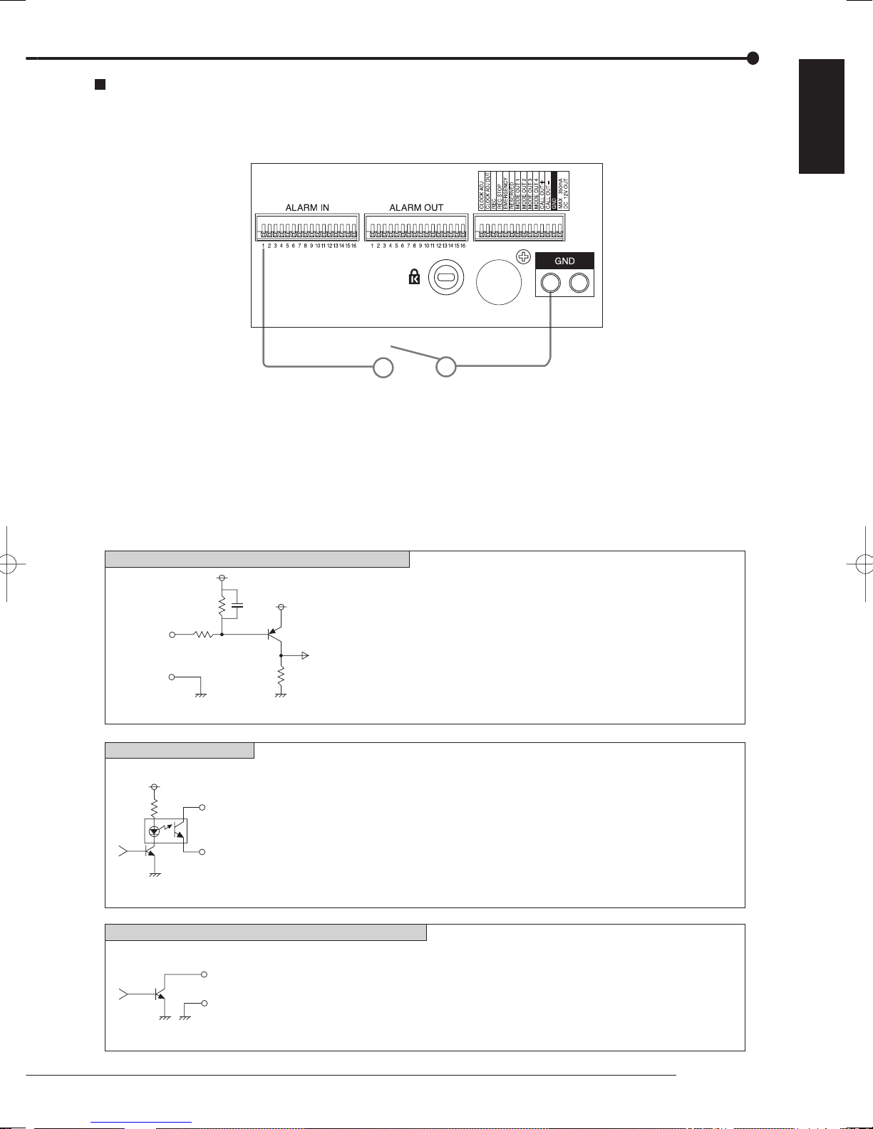
Alarm recording connection
The diagram below shows an example connection for setting alarm signal to sensor number 1.
Alarm switch
ENGLISH
EMERGENCY/ALARM IN/REC/CLOCK ADJ input terminals
[Input Circuit]
10kΩ
Input
terminal
GND
<Interface circuit inside of the unit>
CALL OUT output terminal
[Output Circuit]
<Interface circuit inside of the unit>
ALARM OUT/MODE OUT 1 to 4/CLOCK ADJ output terminals
[Output Circuit]
5V
0.047µF
22kΩ
4.7kΩ
CALL OUT + terminal
CALL OUT - terminal
Output terminal
GND terminal
5V
[Input condition]
[Input interval]
[Specification]
[Specification]
[Specification]
ground of 200 ms or more
1 second or more
Active: When terminals are short-circuited or “Low” Level is applied.
Non active: Open.
Warning signal (Photo coupler output)
Active: Short Max. Drive current 7 mA DC.
Non active: Open. Max. Voltage +24 V DC.
Active: “Low” Level Max. Drive current 30 mA DC.
Non active: Open. Max. Voltage +24 V DC.
* Be sure to use these terminals within above rated value.
<Interface circuit inside of the unit>
Connections
19
Connections (continued)
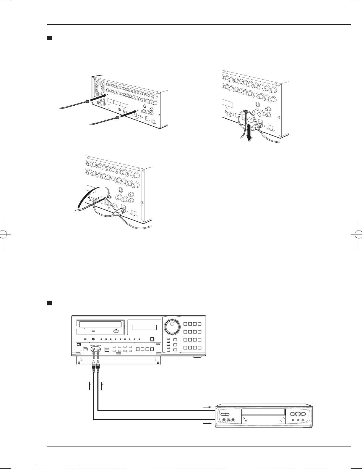
Clamping the cables
step
1. Put the supplied cable clamping band into the
clamper hole on the rear panel.
• There are 2 clamper holes on the unit, for power
cable and USB cable.
step
2. Put the cable to be clamped through the cable
clamping band as illustrated below.
• Face the serrated surface of the band inside.
step
3. Pull the edge of the cable clamping band until it
stops.
Connecting to an analogue video cassette recorder
To VIDEO OUT
connector
To AUDIO OUT
connector
Commercially available audio cable
Commercially available video cable
20
To AUDIO IN
connector
To VIDEO IN
connector
Analogue video cassette recorder

Optional items
DX-ZD5UE(Z)
HDD extension unit (serial bus connection type)
The various external HDDs can be connected to this unit in
order to expand the memory or to use as the copy device.
However, during recording or playing back a picture at high
rate, some pictures may be missed due to the slow rate of
data transfer or the slow speed of response from the external
device connected. Be sure to check the operation suffi ciently
in advance.
Do not use the power control function of the external device
which uses bus power of this unit.
DX-RM5(ZD)
Rack mount adapter for HDD extension unit DX-ZD5UE(Z).
DX-KB5UE
Keyboard for digital recorder
R-2500
Wired remote controller
(Menu setting, search, and PTZ preset function are not available with wired remote controller.)
Consult your dealer for the functions related to PTZ.
DX-RM4
Rack mount adapter for digital recorder DX-TL4516 series.
Recommended items
Consult your dealer about the recommended external devices.
The external device to be used may be unsuitable for the
operation you want to set. It is recommended to consult your
dealer when using the external device.
The various external HDDs can be connected to this unit in
order to expand the memory or to use as the copy device.
However, during recording or playing back a picture at high
rate, some pictures may be missed due to the slow rate of
data transfer or the slow speed of response from the external
device connected. Be sure to check the operation suffi ciently
in advance.
ENGLISH
Connections
21
How to set the menus
Setting the menus
The operations of this unit can be set via a menu displayed on OUTPUT A monitor. You can select and set the menu by using
the buttons on the front panel or using a USB mouse connected to the unit. When using the front panel buttons, the numbers
1-16 (camera number buttons) and letters A to E (SPLIT screen buttons) represent the GUI button of the menu screen.
The menu can only be displayed through OUTPUT A monitor. The menu cannot be displayed through OUTPUT B monitor.
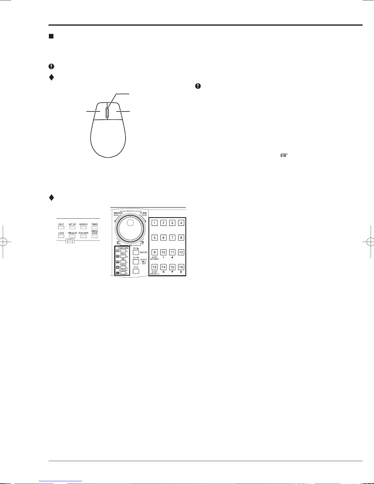
Setting the menu using a mouse
Mouse is not supplied with this unit.
Wheel
Right buttonLeft button
Mouse
Use the standard USB mouse which has left and right
buttons as illustrated to the left. Note that you cannot
use the mouse with this unit depending on the mouse
connected.
step
1. Use the left and right mouse buttons to set the
menu.
• Click the left button to open the menu or select
a needed item, etc.
• Click the right button to set the active area for
motion detection function. (
• The wheel on a mouse does not work with this
unit.
page 56)
Setting the menu using the front panel buttons
step
1. Use the SET UP button, camera number buttons,
and the SPLIT screen buttons (A to E) to set the
menu.
• Press the SET UP button to display the menu
screen.
• Press the camera number buttons (1 to 16)
and the SPLIT screen buttons (A to E) to open
each menu or to select the needed item.
22
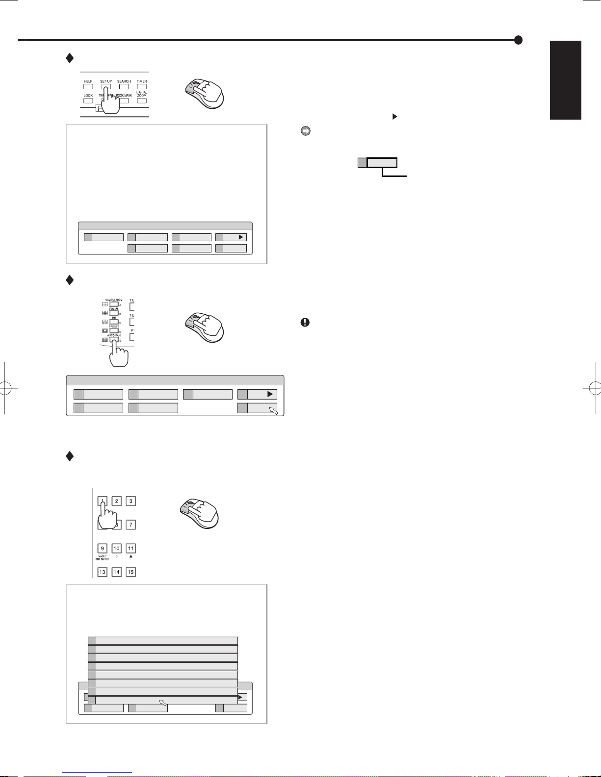
Displaying a menu screen
step
1. Press the SET UP button or click the left button on
the mouse to display a menu.
• The <User Menu> appears.
• To open other menu, press the D button or leftclick on “Next
.”
When you use a mouse, click the following area to
operate.
Exit
E
Click this area
ENGLISH
User Menu
Search
1
2
Protect Data
5
Copy
Closing a menu screen
Setup Menu
1
4
Recording
System
2
5
Timer
Menu Data
Selecting an item
Information
3
PTZ Control
6
3
Motion Det
100 000 000
Next
D
E
Exit
200 000 000
Next
D
E
Exit
step
1. Press the E button or left-click on the “Exit” to close
the menu.
You cannot close the menu by pressing the SET UP
button on the unit.
step
1. Press the front panel button of the needed item
number or left click on the needed item.
• The selected item menu opens.
• Select an item and press the number, or click
on the menu to open the item.
Exit
E
Reset to Factory Setting
7
On Screen Display Setting
6
Multiplexer Setting
5
Password Setting
4
Rear Terminal Setting
3
Setup Menu
Menu Language Selection
2
Recording
1
Time/Date Setting
1
System
4
2
5
Timer
Menu Data
3
Motion Det
200 000
Next
D
Exit
E
How to set the menus
23

How to set the menus (continued)
Inputting numbers
Time Date Setting
Time Date Setting
01 - 01 0620 00
Set time and date.
Day Light Saving Setting
Setting parameters
Time Date Setting
Time Date Setting
01 - 01 0620 00
Number input area
0000::-
14 16
Auto
A
0000::-
E
241 000 000
Set >
D
Return
241 000 000
Using the front buttons of the unit:
step
1. Press the camera number buttons (0 to 9) to input
and use that number.
?
• The number displayed in red can be changed.
step
2. To move to the next input area, press the 16 button.
To go back to the previous area, press the 14
button.
Using a mouse:
step
1. Left-click on the number in red until the needed
number appears.
To change another area, left-click on the needed
area or left-click
step
1. Press the A button or left-click on the parameter box
or .
until the item to be set appears.
• For some items, more detailed setting is
required. In this case, an item such as “D(Set
>)” is displayed. If necessary, press the D
button or left-click on the “Set >” to set more
details.
When you close the menu, press the E button or left
click on “Return” or “Exit.”
?
You cannot close the menu by pressing the SET UP
button on the unit.
Set time and date.
Day Light Saving Setting
14 16
Auto
A
Set >
D
Return
E
Setting or selecting area
24
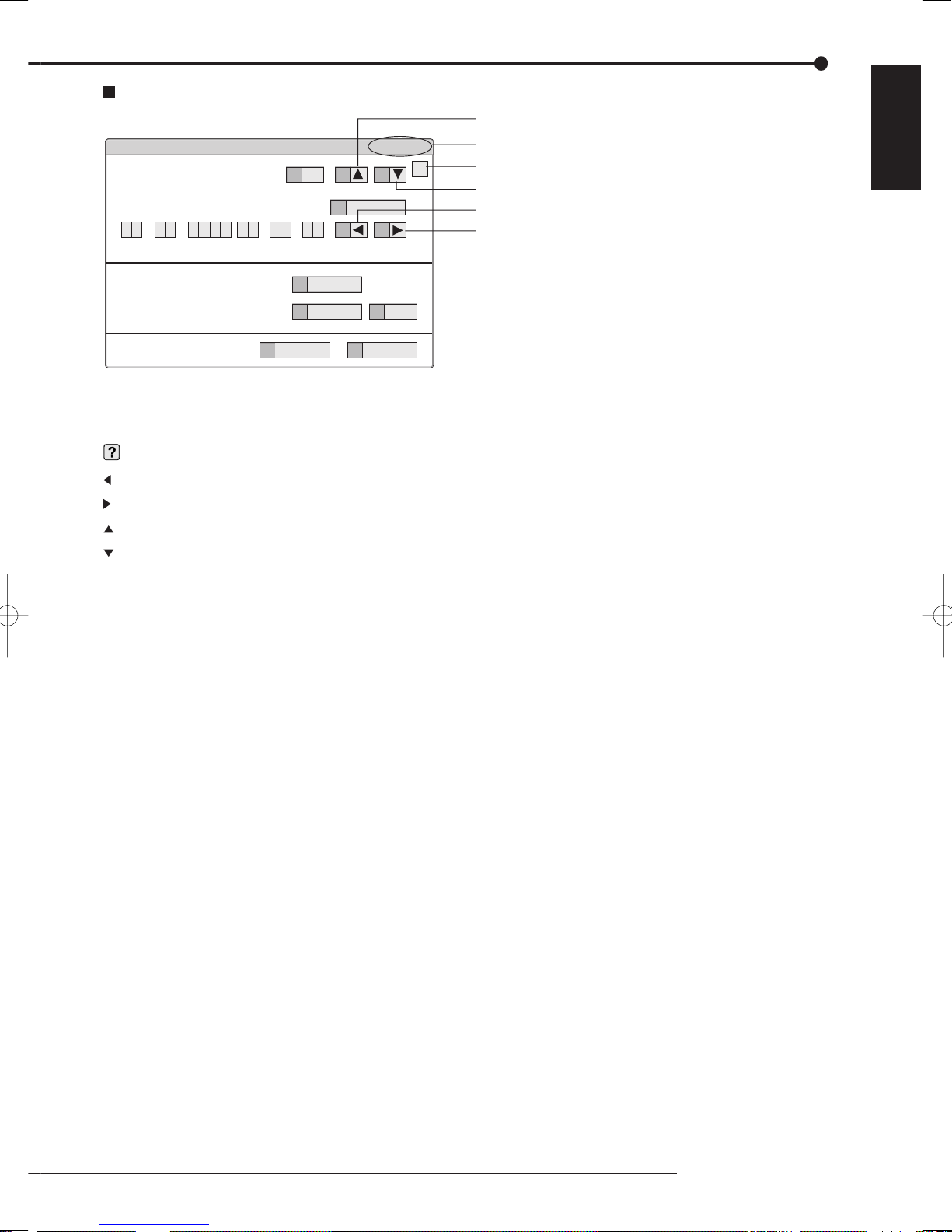
Symbols in the menus
Motion Search (Main - Normal)
Camera Select
Search Start Position
01 - 01 0620 00
Setup date search starts from.
Up button
116 000 000
11 15
1
A
?
Menu address
Help button
ENGLISH
Down button
Oldest
13
0000::-
14 16
Left button
Right button
Motion Detection Settings
Same as Recording Setting
D
B
C
Search
Next >
Motion A
same
12
Return
E
Some symbols appear in the menu screens. The meanings are as follows.
(Help) When you press the HELP button or click this symbol, the detailed information on the menu appears.
(Left) When you press the 14 button or click this symbol, the item to be set shifts to left.
(Right) When you press the 16 button or click this symbol, the item to be set shifts to right.
(Up) When you press the 11 button or click this symbol, the value of selected item increases.
(Down) When you press the 15 button or click this symbol, the value of selected item decreases.
Menu address A unique number for each menu page. You can go directly to each menu page by inputting the menu ad-
dress number using the front buttons of the unit.
For example, when opening the <Motion Search> menu, press the SET UP button and then press the cam-
era number button in the order of 1, 6.
How to set the menus
25

Setup Wizard
Setup Wizard
The setup wizard is displayed when the unit is turned on for
the fi rst time. The Wizard enables a quick setup.
Only when the unit is turned on for the fi rst time, the setup
wizard screen is displayed automatically. It is not displayed next time the unit is turned on.
Turn on the power for the first time
step
2
Select whether or not to use Setup Wizard
step
3
Language Selection
D
step
4
Time Date Adjust
D
Day Light Saving
A+C
step
5-1
HDD Connection
D
step
5-2
HDD Selection
2
Detailed setting (Internal HDD)
1
Detailed setting (serial bus HDD)
2
step
6-1
HDD Configuration
D
step
6-2
Partition setting
2
step
7
Select whether or not to set normal recording conditions
D
step
8
Recording Setup (step 1 Camera check)
D
step
9
Recording Setup
D
(step 2 Define regular recording cycle)
step
10
Recording Setup
C
(step 3 Confirm recording settings for each camera)
5
Camera settings overview
step
11
Finish
D
step
1. After connecting the cameras and the monitors, turn
on the MAIN switch on the rear panel and wait until
the ACCESS indicator is turned off, then press the
POWER button on the front panel.
• The <Setup Wizard> screen appears.
The POWER button does not operate while the ACCESS
indicator is fl ashing. Press the POWER button after the
indicator is turned off and “POWER OFF” is displayed on
the LCD display on the front panel.
step
2. Select whether or not to use the setup wizard.
• Select “Go” when you want to use the setup
wizard. If not, select “Quit.” When selecting
“Quit,” the clock starts running from the initial
setting.
Beware that the menu screen cannot be exited while set-
ting the setup wizard. Furthermore some menu screens
which have already been set are not displayed again.
step
3. (When selecting “Go”)
Select the desired language.
• The <Language Selection> screen appears. The
language of the menu can be selected in this
screen.
• Select the desired language and then select
“Execute” when you have changed the setting.
The unit restarts when selecting “Execute.”
• Select “Next” when the language setting does
not have to be changed.
step
4. Set the present time and daylight saving setting.
page 58)
(
• Select “Next” when the setting is completed.
The clock start running when exiting this screen.
step
5-1. Set the connected HDD.
• When you use only the internal HDD, select
“Internal” and then select “Next.”
• When you use the external HDDs, select “Int +
Ext” and then select “Setting” to set the detailed
setting for each HDD.
step
5-2. (When selecting “Setting”)
Make the detailed setting for internal and serial bus
HDDs.
• In the detailed setting screen, select “Main” and
“Copy2” to use the selected HDD as the main
device and copy 2 device respectively. Select
“Free” when the selected HDD is not used as
the main or the copy 2 device.
• When the setting is completed, return to the
screen of step 5-1 and then select “Next.”
step
6-1. Set the HDD confi guration.
Normal: Does not set partition.
Partition: Sets an independent partition for alarm
recording within the total HDD memory. When
selecting “Partition,” set the partition capacity.
• Select “Next” when selecting “Normal.”
• Select “Setting” to set the partition capacity
when selecting “Partition.”
26

step
6-2. (When selecting “Partition”)
Set the desired partition capacity.
Normal Recording Area: The area for normal
recording.
Alarm Recording Area: The area for alarm
recording.
Long Pre-Alarm Area: The area for long pre-
alarm recording.
• Set the partition capacity for each area in 5 %
unit.
• You cannot set “Normal Recording Area” to “0 %.”
• When the setting is completed, return to the
screen of step 6-1 and then select “Next.”
step
7. Select whether or not to make the recording
settings.
• To set the recording settings, select “Next.”
• Select “Quit” to exit the setup wizard without
setting the recording settings. The power of the
unit turns on.
In the recording setting screens, you can return to the
previous screen by pressing the “Return” button.
step
8. (When selecting “Next”)
By selecting “Execute,” the unit automatically
checks the condition of the picture supplied from
the camera and then sets the camera number to be
recorded.
• Select “Next” when the setting is completed.
step
9. Set the recording time.
• Set the recording cycle and the recording hour
per day.
• Select “Execute” when the setting is completed.
step
10. Frame/field, recording rate, and the picture grade
for the camera numbers detected on step 8 are
automatically set.
• The settings made here are used for normal
recording.
• You can adjust the settings manually.
• Select “View” to confirm the settings. Select
“Next” when the setting is completed.
The audio recording is set to “Off.” To record audio, refer
page 53.
to
When recording audio, the continuous recording time
becomes shorter than the time when recording only picture. Check the estimated recording time on the preview
screen of the normal recording.
step
11. Select “Finish” to exit setup wizard.
• The unit boots-up.
ENGLISH
Setup Wizard
27
Menu chart
Menu chart
You can set the basic settings for this unit in the menu settings.
Some of the menu settings cannot be changed during playback, recording, or stand-by mode for pre-alarm recording.
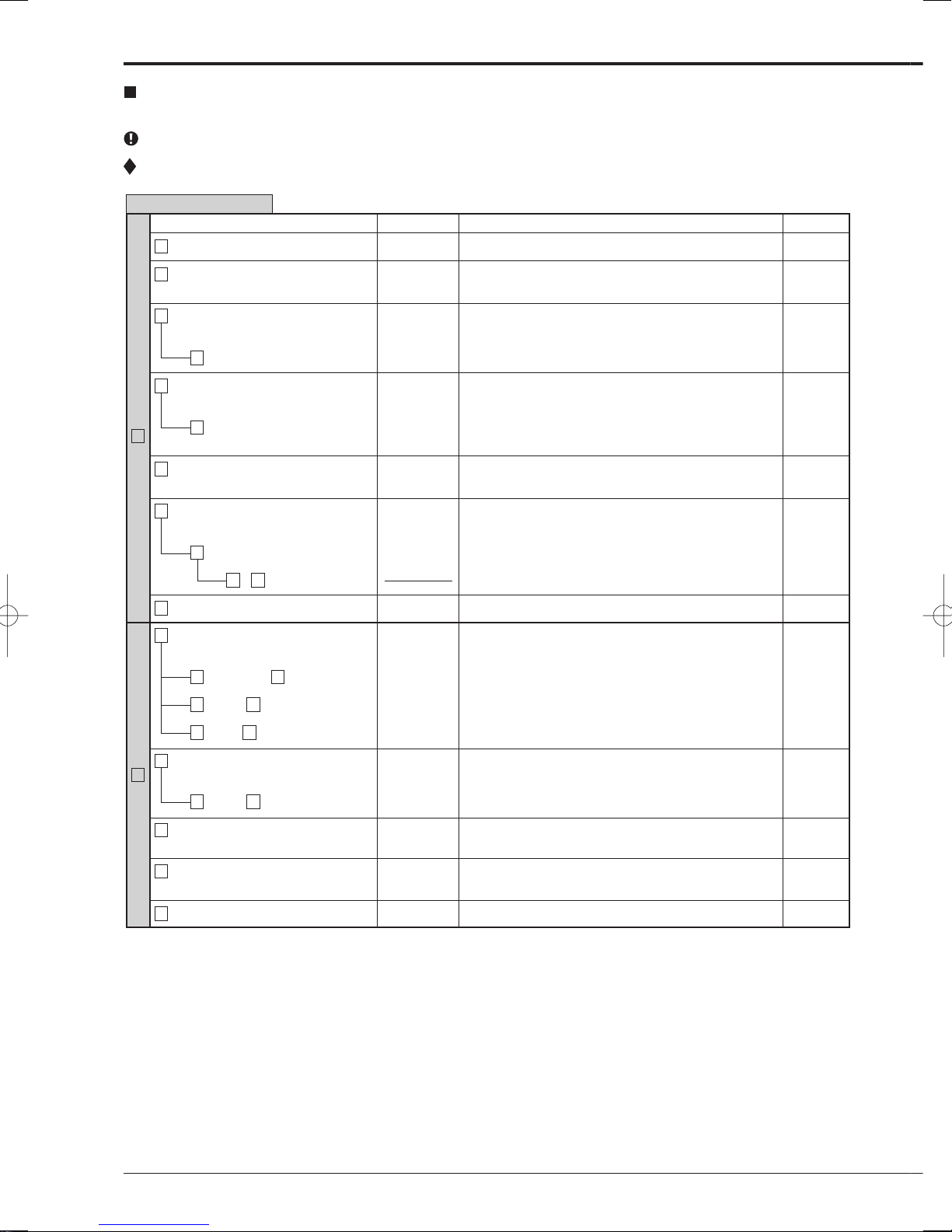
User Menu
User Menu (100 000 000)
Menu
1 Select Source Device 111 000 000
Menu Address
Functions Pages
Selects the device to be played back/searched.
39
2 Search by Time and Date 112 000 000
3 Search by Alarm List 113 000 000
D Alarm List 113 D00 000
4 Find data storage location 114 000 000
D Search (Device Search List) 114 D00 000
Search
1
5 Search by Book Mark 115 000 000
6
Search by Motion
B
A + D Go
E Exit
1 Copy Data to Copy 1 Drive 121 000 000
1 Start/End + 2 Set > 121 2SE 000
1 Start + 2 Set > 121 2S0 000
Next > (Motion Detection Settings)
116 000 000
116 B00 000
Searches the desired picture by specifying the time and
date.
Searches the desired picture from the alarm list registered
at the start of alarm recording.
Displays the list of alarm recording.
Detects the device which is used to record by inputting the
recording period.
Displays the list of devices used to record for the specified
time period.
Searches the desired picture by specifying a bookmark
registered.
Searches camera picture with motions by using motion
detection function during playback.
Sets the condition for motion detection.
Sets the motion detection area manually.
Exits the Search menu.
Copies the data to copy 1 device by specifying the start and
end points of the data. (for short period)
Specifies the start and end points to be copied.
Specifies only the start point of copy.
93
94
94
39
39
39
40
40
40
-
41
41
41
1 End + 2 Set > 121 2E0 000
2 Copy Data to Copy 2 Drive 122 000 000
Copy
2
1 Start + 2 Set > 122 2S0 000
3 Set Copy 1 Drive 123 000 000
4 Set Copy 2 Drive 124 000 000
E Exit
Specifies only the end point of copy.
Copies the data to copy 2 device by specifying only the start
point of the data. (for long term)
Specifies the start point of copy.
Specifies the condition for copying the recorded picture to
copy 1 device.
Specifies the condition for copying the recorded picture to
copy 2 device.
Exits the Copy menu.
41
42
42
41
42
-
28
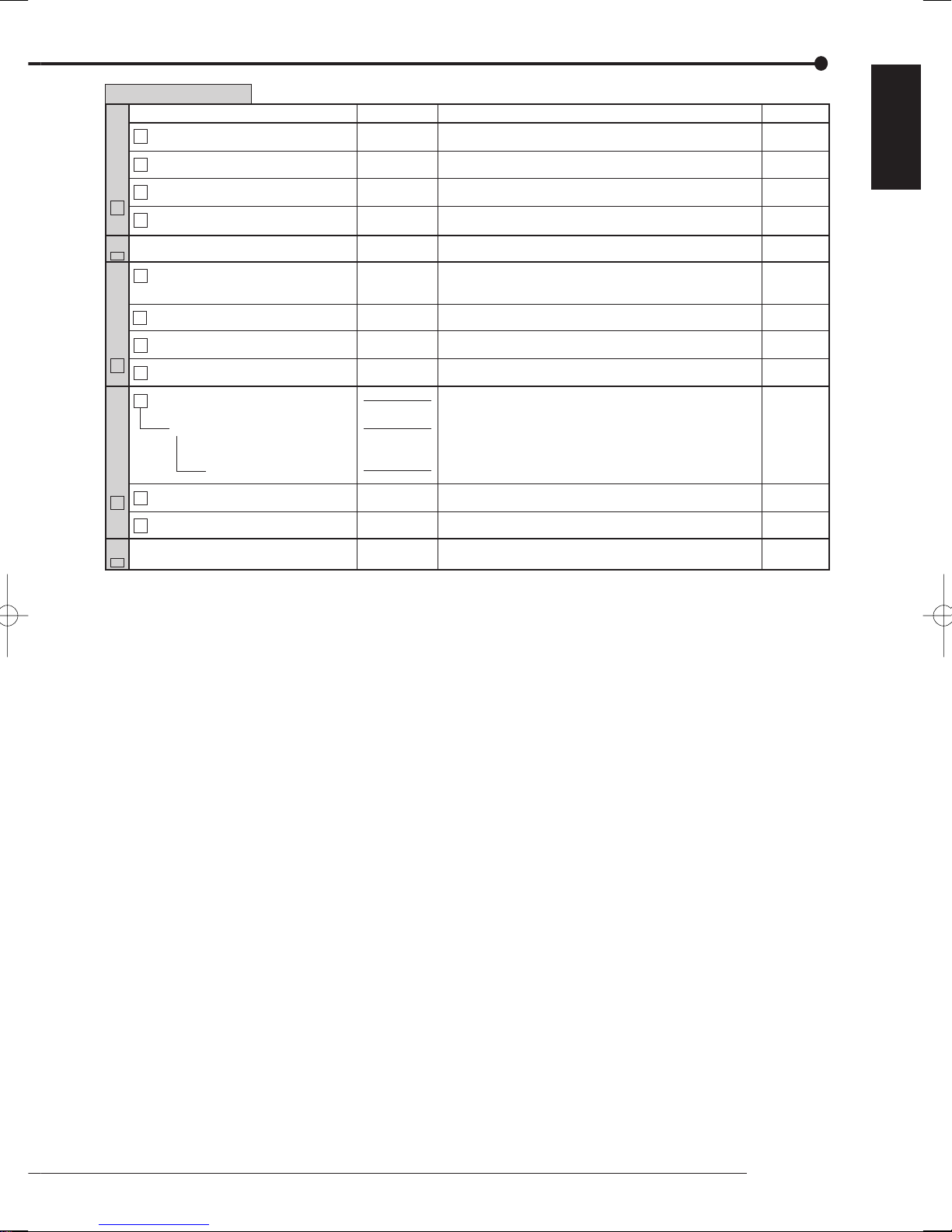
User Menu (100 000 000)
Menu
1 Main Storage Memory Information 131 000 000
2 Copy 1 Drive Information 132 000 000
Menu Address
Functions Pages
Shows the recorded range of each area in the main device.
Shows the recorded range of each group in copy 1 device.
46
46
ENGLISH
3 Copy 2 Drive Information 133 000 000
Information
3
E Exit
Next
D
1 Protect Recorded Data 151 000 000
2 Protected Data Information 152 000 000
3 Change Protected Data Settings 153 000 000
Protect Data
5
E Exit
1 Go to PTZ Control
Zoom, iris, focus adjustment, AutoPan
Preset
PTZ Control
2 Select PTZ Camera 162 000 000
6
E Exit
Exit
E
Shows the recorded range of each group in copy 2 device.
Exits the Information menu.
Proceeds to Setup Menu.
Protects the recorded pictures. Up to 500 areas can be
protected and cannot be overwritten.
Shows and searches the list of protected pictures.
Shows and deletes the list of protected pictures.
Exits the Protect Data menu.
Activates pan or tilt of the PTZ camera connected.
Adjusts the zoom, iris, and focus of the camera. Activates
auto pan.
Presets up to 16 viewing positions.
Switches the PTZ camera to be controlled.
Exits the PTZ Control menu.
Exits the User Menu.
46
-
-
47
47
47
48
48
48
48
-
-
Menu chart
29

Menu chart (continued)
Setup Menu
Setup Menu (200 000 000)
Menu Menu Address Functions Pages
1
Set Recording Pattern A (Normal/Timer)
1 Camera Check 211 100 000
2 Auto + D Set > 211 2AD 000
211 000 000
Specifies the recording setting for recording pattern A.
Selects the camera number to be recorded.
Sets the normal recording setting automatically by
specifying the recording cycle and the recording hour a day.
49-51,110,111
49-51
49-51, 110
D Execute 211 2AD D00
2 Easy + D Set > 211 2ED 000
D Execute 211 2ED D00
2 Manual + D Set > 211 2MD 000
D View > 211 2MD D00
3 Alarm Recording Menu 211 300 000
Recording
1
1 Easy + D Set > 211 3ED 000
D
1 Manual + D Set > 211 3MD 000
D View > 211 3MD D00
4 Alarm Camera Setting 211 400 000
D View > 211 4D0 000
D Next > 211 4DD 000
5 Alarm Trigger In/Out 211 500 000
D View > 211 5D0 000
Execute
211 3ED D00
Shows the preview of the normal recording settings.
Specifies frame or field, recording rate, and picture grade of
normal recording to the same settings for all the camera
numbers.
Shows the preview of the normal recording settings.
Specifies frame or field, recording rate, and picture grade of
normal recording for each camera number individually.
Shows the preview of the normal recording settings.
Specifies the alarm recording settings.
Specifies frame or field, recording rate, and picture grade of
alarm recording to the same settings for all the camera
numbers.
Shows the preview of the alarm recording settings.
Specifies frame or field, recording rate, and picture grade of
alarm recording for each camera number individually.
Shows the preview of the alarm recording settings.
Specifies the sensor settings for alarm recording.
Shows the recording camera for each sensor.
Shows the recording camera for each sensor.
Specifies the trigger and PTZ camera preset settings for
alarm recording.
Shows the preview of the trigger and PTZ camera preset
settings for alarm recording.
49-51
49-51, 110
49-51
49-51, 110
49-51
49-51,110,111
49-51, 110
49-51
49-51, 110
49-51
49-51, 111
49-51
49-51
49-51, 111
49-51
30
 Loading...