

Page 1

DIGITAL RECORDER
INSTALLATION MANUAL
MODEL
DX-TL308E
DX-TL304E
ENGLISHOTHERS
THIS INSTRUCTION MANUAL IS IMPORTANT TO YOU. PLEASE READ IT BEFORE USING YOUR DIGITAL RECORDER.
1
Page 2
Before use
How to use this manual
About this manual
The manual of this recorder consists of the following two
manuals.
Installation Manual (this manual)
This manual describes connections of devices as well as
functional settings and operations to use this recorder.
This manual mainly describes operating procedures carried
out by the mouse.
User's Manual
This manual is for operators of this recorder and describes
the operating procedures for the basic functions only.
Symbols
Tips
(Reference for operation)
Shows information to be referred to when you operate this
recorder.
Notice
(Point to be noted)
Shows information to be noted when you operate this
recorder.
(Reference page)
Shows the sections and pages to be referred to.
Troubleshooting
See "Troubleshooting" ( pages 125 to 127) and take
appropriate measures.
Note
The illustration in this manual shows an example of DXTL308E.
How to locate information in this manual
You can fi nd desired information in this manual using the
following methods.
Table of contents Pages 5 to 7
Reference page Shown in the texts.
How to locate setting items
When you fi rst set up the recorder, you can confi gure the
minimum required settings using the Setup Wizard.
•
Language setting
•
Clock setting
•
HDD operation setting
•
Recording setting
When you confi gure these settings manually or confi gure
other settings, fi nd desired functions and pages describing
those functions using the following methods.
Search based on the function you want to use
See the table of contents (
Search for the setting method for the connected device
See the reference pages shown by the descriptions of
the devices in "Connections" (
Search based on the items displayed on the screen
See the reference pages shown by the descriptions of
the displayed items in "Screen display" (
Search from the quick menu list
You can find the setup menus and recording setting
menus as well as their setting items in the quick menu
lists on
In addition, you can find the factory default setting of
each setting item, too.
Using these lists, you can keep records of your settings
and review them later.
pages 46 to 49 and pages 92 to 98.
pages 5 to 7).
page 24).
page 22).
2
Page 3
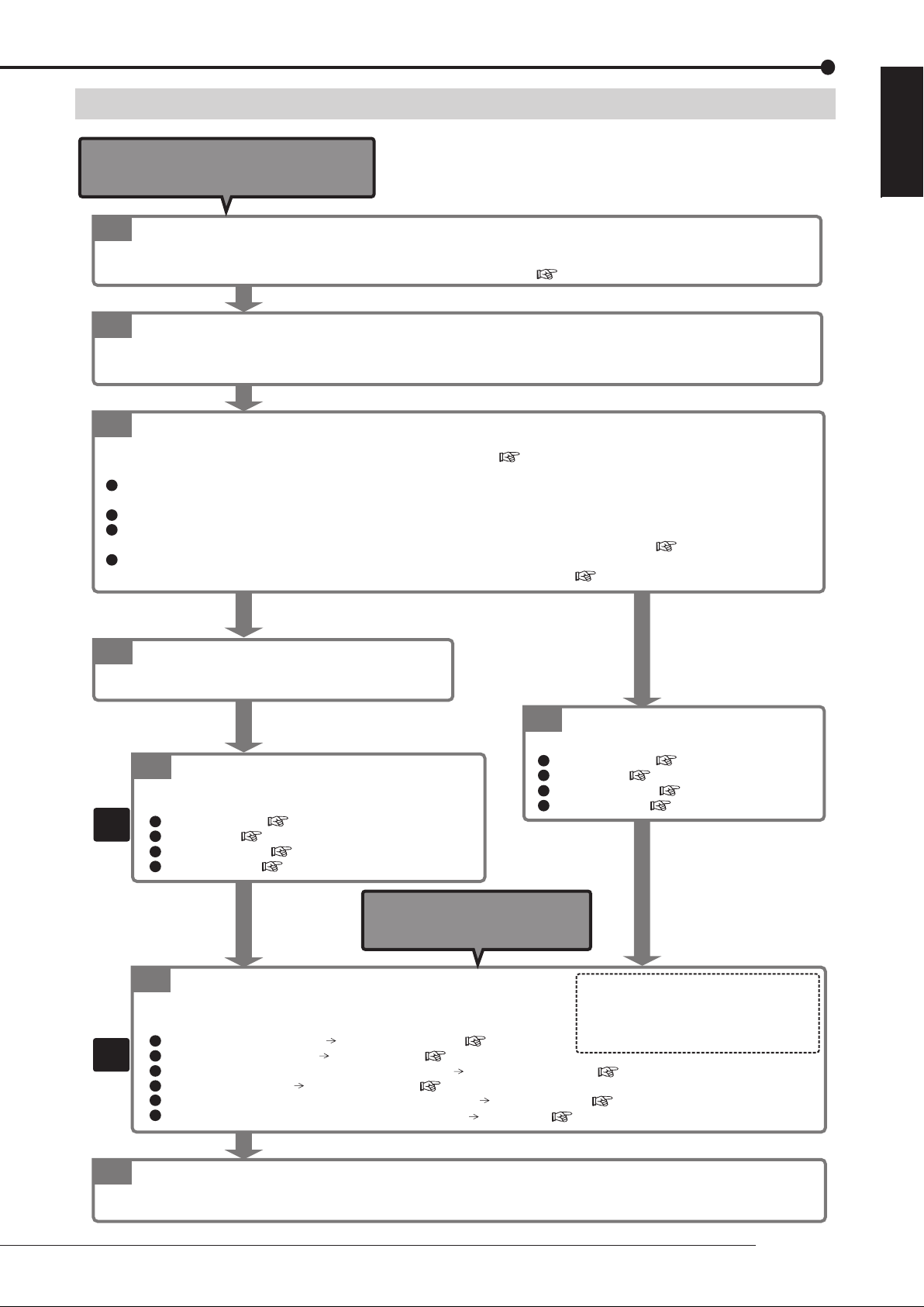
Setup procedure
Start here when you first
set up the recorder.
Connect the recorder.
1
Connect the cameras, monitors, and sensors to the recorder. Configure the settings of the connected devices referring to the
reference pages shown in the descriptions of the devices in "Connections" on page 24.
Turn on the recorder.
2
Turn on the main switch on the rear of the recorder. After checking the POWER indicator goes out, press the POWER button on
the front panel of the recorder.
Select whether or not to use the Setup Wizard.
3
When you turn on the recorder first time, the Setup Wizard is activated. "Setup Wizard" on pages 32 and 33.
Using the Setup Wizard, you can set the following items automatically according to the displayed menus.
Language setting
The language used for the menu screen is selected.
Clock setting
HDD configuration
All the connected HDDs are registered as Main device. For details of the HDD configuration, see pages 34 to 37.
Recording setting
The settings for normal recording are configured. For details of the recording, see pages 44 to 55.
ENGLISH
When using the
Setup Wizard
4-1
Run the Setup Wizard.
Set the items shown above according to the displayed menus.
(To change the
settings made by
the Setup Wizard)
Change the settings made by the
4-2
Setup Wizard.
To manually change the settings made by the Setup Wizard:
As
needed
As
needed
Language setting
Clock setting
HDD configuration
Recording setup
Page 99
Page 99
Pages 34 to 37
Pages 44 to 55
Start here when you change
the settings of the
recorder already set up.
Make other settings.
5
Make the necessary settings according to your desired recording operation.
For example,
To carry out timer recording. Timer program setting pages 62 to 65
To use the mirroring mode. Mirroring setting page 35
To control the recorder from the personal computer. Communication setting pages 108 and 109
To control the camera. PTZ camera setting page 110
To restrict the recorder's functions by the password lock. Password setting pages 111 to 114
To make settings of screen display and rear terminals. Setup menu pages 92 to 110.
When not using the
Setup Wizard
4
Make the minimum required
settings manually.
Language setting
Clock setting
HDD configuration
Recording setup
How to search for necessary settings
Refer to "How to locate setting items" on the left
page, and find the pages describing the
functions and settings you want to use and
configure the necessary settings.
Page 99
Page 99
Pages 34 to 37
Pages 44 to 55
Check the setup condition.
6
By executing recording, playback, search, and copy, check that the recorder has been set up correctly.
Beginning
3
Page 4

Major features
This digital recorder is able to record images captured by up to 8 (DX-TL308E)/4 (DX-TL304E) surveillance cameras and
audio received by microphone to its hard disk. The recorder is equipped with the function to search for desired scenes by
specifying the recording dates as well as the simultaneous recording/playback function that allows playback even during
recording. In addition, using the split display function to display up to 8 (DX-TL308E)/4 (DX-TL304E) camera images on one
screen, you can view more than one monitored area at the same time. This recorder facilitates to confi gure a monitoring
system for constant surveillance.
Realizing long-term recording
By reducing the size of recorded video data using the newly developed video compression engine (MEPG 4 system), the
writing capacity of HDD can be saved about 50% (compared with our conventional models). In addition, this recorder is
designed to connect external HDD to expand its HDD capacity up to 8 TB (when using optionally available DX-ZD6UE). Due
to this, you can construct a long-term recording system to store data for 2 years, for example.
Simple operation and USB mouse connectable
By connecting a separately available USB mouse to the serial bus terminal on the recorder, you can easily control the
recorder and setting menus. For frequently used functions such as search and copy, the simple operation menu allows you
to operate them by simple procedure. This recorder is equipped with the on-screen help function. By clicking the help icon or
pressing the HELP button, you can view various information such as operation procedures on the screen.
"One touch copy" for easy copying with one button press
The recorder is equipped with the function to copy still playback images to a USB memory device set in the recorder or a
disc in an external drive with one button press. You can select still images or moving images to copy. When selecting moving
images, you can specify the recording duration.
XGA output terminal integrated (DX-TL308E only)
You can connect a general PC display monitor to this terminal to use it as a surveillance monitor.
Motion detection search function
By designating certain areas such as doors and windows shown in recorded images as detection target areas, you can
search for recorded data containing scenes having variation (or motion) in those areas and display the beginning of such
data. This function is useful, for example, in searching for intruders into deserted places or scenes where someone painted
graffi ti on the wall.
Personal information protection function
By setting passwords, you can classify the recorder operations into 3 levels. You can set a password for deleting data from
HDD to protect them from unauthorized access or to use this function as misuse prevention. The recorder is equipped with
the function to prohibit playback of data recorded before the number of days you specify (auto expiration setting), which
facilitates data management according to your operation standard regarding the data storage period.
Alarm notifi cation of intrusion and system errors
When an alarm signal is input to the recorder from external body sensors or when an error is detected in the system,
the recorder notifi es the designated personal computer via TCP/IP command or e-mail. The recorder is also capable of
transferring the alarm-recorded images that is triggered by an external alarm signal to the designated FTP server.
Microsoft is either registered trademarks or trademarks of Microsoft Corporation in the United States and/or other
countries.
All other company and product names appearing herein are the property of their respective owners.
4
Page 5

Contents
Beginning
Before use ......................................................................2
How to use this manual ..............................................2
About this manual ....................................................2
Symbols ...................................................................2
Troubleshooting .......................................................2
Note ........................................................................2
How to locate information in this manual .................2
How to locate setting items ................................2
Setup procedure ............................................................3
Major features ................................................................4
Contents ......................................................................... 5
Caution and care ...........................................................8
Note ..............................................................................15
Open source software ...............................................15
MPEG-4 patent ...........................................................15
Major operations and their functions ........................ 16
Front view ...................................................................16
Front view (inside of door) .......................................18
Rear view ....................................................................20
Screen display ...........................................................22
Connections
Connections .................................................................24
Connecting CCTV cameras, monitors, and sensors
.........................................................................24
Connection for alarm recording ...............................25
Cable clamping ..........................................................26
Connecting an analog VCR ......................................26
Optional products ......................................................26
Recommended products ..........................................26
Caution for connecting additional hard disk units
.........................................................................27
Caution in installing multiple recorders in an EIA
rack ..................................................................27
Menu settings/Device registration
How to set the menus .................................................28
Displaying the menus ...............................................28
Operating the menus .................................................29
Closing the menus ....................................................29
Using the mouse operation screen ..........................30
Using the Setup Wizard ..............................................32
Making the minimum required settings automatically
<Setup Wizard>
.......................................................32
Registering the devices .............................................. 34
Setting Main, Copy, and Archive devices
<HDD registration>
Cautions for using external devices .................34
Hookup and operation setting of HDDs ............34
................................................34
Order of recording and playback of the internal
and external HDDs registered as Main device
....................................................................34
Registering the internal HDDs ...............................35
Mirroring ...........................................................35
Registering external HDDs ....................................36
Checking the registered devices ............................37
Setting the repeat recording and partition of Main
<Main HDD setting>
device
Setting the repeat recording ...................................38
Setting the partition ................................................39
......................................38
Viewing images
Viewing images captured by the cameras
Multiplexer function ...................................................40
Single screen display .............................................40
Split screen display ................................................40
Sequential display ..................................................40
Switching Output A and B ......................................41
Operating the DIGITAL ZOOM button ....................41
Triplex playback .....................................................42
.................. 40
Controlling the cameras .............................................43
Controlling the cameras using the menus ..............43
Recording
Recording ....................................................................44
Recording methods ...................................................44
Recording types .........................................................44
Before making recording settings ...........................45
Playback during recording .....................................45
Procedure of confi guration of recording settings ..46
Making recording settings automatically
.........................................................................50
Camera check ..................................................50
Defi ne the normal recording cycle ....................50
Confi rm the recording settings .........................50
Apply new settings ...........................................50
Making recording settings manually
.........................................................................51
Recording A to D ....................................................51
Picture size .......................................................51
Picture quality and FPS ....................................52
Alarm camera setting .......................................53
Alarm input/output ............................................54
Supplementary explanations on recording settings
....................................................................54
Supplementary explanations on preliminary
recording .....................................................55
Emergency recording settings
Supplementary explanations on emergency
recording .....................................................57
Motion detection settings
Cautions on motion detection setting ...............59
Audio recording settings
Stopping alarm input .................................................61
<EMR recording>
<Motion detection>
<Audio recording>
<Auto setting>
<Manual setting>
............56
..................58
....................60
ENGLISH
Beginning
5
Page 6

Contents (continued)
Manual recording .......................................................61
Before starting manual recording .....................61
Timer recording settings
<Timer program>
......................62
When timer programs overlap ..........................65
Playback
Playback ....................................................................... 66
Selecting the playback device
<Device selection>
...........66
Playing back recorded data ......................................66
Search
Searching for images you want to view ....................68
Searching for the oldest recorded data
<Start point search>
..................................................68
Searching for the latest recorded data
<End point search>
...................................................68
Setting the searching conditions .............................69
Searching images based on the designated
data and time
<Time date search>
Searching from the alarm list
..........................70
<Alarm list search>
............70
Copying images registered in the alarm list .....71
Searching for images with motion
Searching for images using various playback functions
<MD search>
..........72
..73
Forward/rewind playback .......................................73
Frame-by-frame playback ......................................73
Reverse playback ..................................................73
Changing the playback rate ...................................73
Playing back the latest recorded image .................73
Caution in various playback functions ..............73
Searching for bookmarked images ...........................74
Registering a bookmark ............................................74
Searching for bookmarked images ..........................74
Copy
Copying recorded data ...............................................75
One-touch copy .........................................................75
Copying data by specifying the copy range ...........75
Setting the copy conditions ....................................75
Copying data by specifying the start time and
data size ...........................................................76
Copying data by specifying the end time and
data size ...........................................................76
Copying data by specifying the start time and
end time ...........................................................77
Caution in copying data ....................................77
Archiving data ............................................................78
Copying data from the recorded to videotape ........79
Communication
Using the communication functions .........................80
Communication functions of this recorder .............80
Restrictions on network users ................................80
Bandwidth control ..................................................80
Cautions in communicating by the Web browser or
PC viewing/communication software ...............80
Cautions regarding the same setting items
displayed on multiple screens ..........................80
Communication by Web browser .............................80
PC system requirements ........................................80
Connections ...........................................................81
Login .....................................................................81
Notes on the Main Menu ..................................81
Viewing live images ...............................................82
Playing back recorded images ...............................83
Searching recorded images ...................................83
Searching for images by designating date and
time .............................................................83
Searching for images using the alarm list ........83
Setting the Main Menu ...........................................84
Changing user settings .....................................84
Setting the titles of the recorder and cameras ..85
E-mail setup ......................................................86
FTP notifi cation setup .......................................88
Connection mode setup ...................................89
Clock setup .......................................................90
Logout ....................................................................90
E-mail notifi cation ......................................................91
FTP notifi cation ..........................................................91
Communication by the viewing/communication
software ..........................................................91
Others
Various settings ...........................................................92
How to display the Setup menu .............................92
Quick reference chart for the Setup menu .............92
How to use the quick reference chart for the
Setup menu ................................................92
Settings of the present time and menu language
<Clock and language>
...............................................99
Clock setting .....................................................99
Language setting ..............................................99
Settings related to the warning display and rear
terminals
<Warning display · EXT terminal setting>
.........99
Warning display · Buzzer · Call-out 1 .....................99
Remain .............................................................99
Button sound ..................................................100
Start alarm recording ......................................100
Communication ..............................................100
Warning display • Buzzer • Call-out 2 ..................100
Mode-out • Remaining capacity ...........................101
Mode-out 1 and 2 ...........................................101
Remain 1 and 2 ..............................................101
Event terminal ......................................................102
On-screen display settings
<Information display setting>
.......................................................................102
Clock display mode and location .........................102
Recorder status and title display ..........................102
Camera number and title display .........................103
Use the transparent menu ...................................103
Multiplexer settings
<Multiplexer setting>
........................104
Output A/Output B ................................................104
Copy Output A settings ...................................104
6
Page 7

4-split and 9-split ............................................104
Sequential display ..........................................104
Alarm display .......................................................104
Covert camera .....................................................105
XGA output (DX-TL308E only) .............................105
Settings related to playback
<Setting the playback functions>
Activate repeat playback ................................105
Display a playback image in fi eld ...................106
Image originality check play ...........................106
Auto expiration on the specifi ed date .............106
Settings related to the menus
<Loading/saving/initializing the menu settings>
Loading the menu settings .............................107
Save the menu settings ..................................107
Initialize the menu settings .............................107
Settings related to communication
<Communication setting>
RS-232C setting ...................................................108
LAN setting .........................................................108
LAN service port settings ...............................108
E-mail notifi cation - Address setting ...............108
IP alarm notifi cation - Address setting ............109
FTP transmission settings ..............................109
PTZ camera setting .............................................. 110
Restricting the operations of the recorder
Simple lock ...............................................................111
Enabling the simple lock ................................. 111
Disabling the simple lock ................................ 111
Password lock .......................................................... 111
Registering a password .......................................112
Enabling the password lock .................................112
Disabling the password lock ................................112
Password for restricting operations
(Levels 1 to 3) ........................................... 112
Password lock for HDD protection .................113
Changing a password ..........................................113
Password for restricting operations
(Levels 1 to 3) ........................................... 113
Password for HDD protection .........................113
Changing the lock mode from the password lock
to simple lock .................................................114
Changing the operation restriction level ............... 114
..................................105
..................107
..........................................108
.................. 111
Protecting recorded data .......................................... 115
Protecting recorded data ........................................115
Checking the protected data ..................................115
Disabling data protection ........................................115
Deleting recorded data ............................................. 116
Deleting recorded data ............................................116
Reducing the load on the HDD ................................. 117
Stopping the rotation of HDD that is not in use for
recording
<HDD sleep mode>
............................... 117
Displaying the device information ........................... 118
Checking the registered devices and
recorded data area ....................................... 118
Displaying the <Device information> screen ........ 118
Displaying the Main device information ...............118
Displaying the Copy device information ...............118
Displaying the Archive device information ...........118
Displaying the system log ........................................ 119
Displaying the system log ......................................119
Function against power failure ................................120
Power failure compensation circuit ......................120
Power failure recovery recording .........................120
Record of turning-off of the MAIN switch on the
rear panel .......................................................120
RESET button ......................................................120
Operation examples
Operation examples ..................................................121
Operation example 1 ...............................................121
Operation example 2 ...............................................122
Operation example 3 ...............................................123
Troubleshooting
Troubleshooting ........................................................124
Checking the status of the recorder
.......................................................................124
Error indications ......................................................128
Warning indication and call-out signal output
<Self-check function>
..128
Glossary/Specifi cations
Glossary ..................................................................... 132
Specifi cations ............................................................ 133
ENGLISH
Beginning
7
Page 8

Caution and care
HEAVY OBJECTS SHOULD NEVER BE PLACED ON THE UNIT (E.G., MONITOR)
NEVER TOUCH OR INSERT ANY OBJECT INSIDE THE UNIT
Touching the inside of the cabinet or inserting foreign objects of any kind through ventilation holes not only creates a safety
hazard but can also cause extensive damage.
PROTECT THE POWER CORD
Damage to the power cord may cause fi re or shock hazard. If the power cord is damaged, turn OFF the MAIN switch and
carefully unplug the cord by holding the main plug.
If this unit is moved with the power on status, the built-in HDD may be damaged. Confi rm that more than one minute have
passed since the power cord and the connecting cords were disconnected, then move this unit.
UNPLUG THE POWER CORD DURING A LONG ABSENCE
Turn off the power and unplug the power cord during a long absence.
MAINTAIN GOOD VENTILATION
Do not obstruct the many ventilation holes on the unit. For maximum ventilation, leave some space around the unit and place
the unit on a hard level surface only, and ensure it is not covered during use. Heavy objects should never be placed on the
unit.
WHEN NOT IN USE
When not in use, always turn OFF the MAIN switch.
CABINET CARE
Never use petroleum-based cleaners. Clean with a soft cloth moistened with soap and water and wipe dry.
PVC cables or leads should not be left in contact with the cabinet surface for long periods.
INSTALLATION LOCATION
For excellent performance and lasting reliability install in a location that is:-
1. Well ventilated, out of direct sunlight and away from direct heat.
2. A solid vibration-free surface.
3. Free from high humidity, excessive dust and away from magnetic fi elds.
4. Please ensure that the ventilation fan located on the unit’s back panel is not blocked.
UNSUITABLE LOCATIONS
Placing the unit in the following places might shorten the product life:
• Extremely cold places, such as refrigerated warehouses and ice houses
• Places where excessive hydrogen sulfi de is likely to be generated, such as hot-springs areas
• Places or locations with salt air environment.
THIS EQUIPMENT DOES NOT PROVIDE CONNECTION FOR USED WITH OUTDOOR OR CABLE DISTRIBUTION
SYSTEMS.
NO OBJECTS FILLED WITH LIQUIDS, SUCH AS VASES, SHALL BE PLACED ON THE APPARATUS.
DO NOT PLACE HEAVY OBJECT ON THIS UNIT.
DO NOT STEP ONTO THIS UNIT.
The unit may drop or fall by losing its balance. It may cause injury or failure of the unit.
WARNING: TO PREVENT FIRE OR SHOCK HAZARD, DO NOT EXPOSE THIS APPARATUS TO RAIN OR MOISTURE.
THIS APPARATUS MUST BE GROUNDED.
MAINS LEAD CONNECTION
The mains lead on this Unit is fi tted with a non-rewireable mains plug, incorporating a 5A fuse. If you need to replace the
fuse, use a 5A fuse approved by BSI or ASTA to BS 1362, ensuring you refi t the fuse cover. If the mains plug is not suit-
able for the sockets in your home, and you require to remove the plug, remove the fuse, cut off the plug then dispose of
the plug immediately, to avoid a possible electric shock hazard. To refi t a new plug, follow these instructions; Green-and-
yellow: Earth, Blue: Neutral and Brown: Live. As the colours in the mains lead of this Unit may not correspond with the
coloured markings identifying the terminals in your plug, proceed as follows.
•
The wire which is coloured green-and-yellow must be connected to the terminal in the plug which is marked by the
letter E or by the safety earth symbol
•
The wire which is coloured blue must be connected to the terminal which is marked with the letter N or coloured
black.
•
The wire which is coloured brown must be connected to the terminal which is marked with the letter L or coloured red.
or coloured green or green-and-yellow.
8
Page 9
This unit complies with the requirements of the EC Directive 2004/108/EC, “EMC Directive” and 2006/95/EC, “Low Voltage Directive”. The requirements for the susceptibility according to EN 55024 and the requirements for interference according to EN 55022 are observed for the operation on residential areas, business, light industrial premises and in small
scale enterprises, inside as well as outside of the building. All places of operation are characterised by their connection
to the public low voltage power supply system. This unit is manufactured in accordance with EN 60950-1.
Warning
This is a class A product. In a domestic environment this product may cause radio interference in which case the user
may be required to take adequate measures.
Note: This symbol mark is for EU countries only.
This symbol mark is according to the directive 2002/96/EC Article 10 Information for users and Annex IV,
and/or to the directive 2006/66/EC Article 20 Information for end-users and Annex II.
Your MITSUBISHI ELECTRIC product is designed and manufactured with high quality materials and components which
can be recycled and/or reused.
This symbol means that electrical and electronic equipment, batteries and accumulators, at their end-of-life, should be
disposed of separately from your household waste.
If a chemical symbol is printed beneath the symbol shown above, this chemical symbol means that the battery or
accumulator contains a heavy metal at a certain concentration. This will be indicated as follows:
Hg: mercury (0,0005%), Cd: cadmium (0,002%), Pb: lead (0,004%)
ENGLISH
In the European Union there are separate collection systems for used electrical and electronic products, batteries and
accumulators.
Please, dispose of this equipment, batteries and accumulators correctly at your local community waste collection/
recycling centre.
Please, help us to conserve the environment we live in!
About the hard disk drive (HDD)
•
This unit is equipped with HDD, which is a very delicate device. Therefore, handle this unit carefully.
•
Don't expose this unit to vibrations and shocks. It may be damaged when exposed to vibrations and shocks especially
during power-on or access to the HDD.
•
Don't unplug the power cord during recording/playback or power-on.
•
This unit is equipped with a system that automatically resumes and continues recording in the event of a minor failure
in the HDD or other components during recording. However, depending on the type of a failure in the HDD, this unit
may not able to continue recording. For early detection of failures, it is recommended to have this unit inspected every
year.
•
In the event of a fault in the HDD, replace it immediately. For replacement of the HDD, please contact your Mitsubishi
dealer. (To replace the HDD, it is required to stop recording.)
•
Use recommended HDD only. For HDD supported by this unit, please contact your Mitsubishi dealer.
•
When the HDD is replaced, the recorded data are deleted. To ensure stable operation of this unit, the fi rmware may be
updated from time to time. The recorded data may be deleted in such a case.
•
When you dispose of or transfer this unit, handle the video data stored in HDD carefully and take all responsibilities
related to the disposal or transfer.
•
In the event of a failure in the HDD during normal recording or mirroring, this unit may not be able to resume recording
after rebooted, depending on the failure condition.
•
When you enable the mirroring function while the recorded data are stored in the HDD, the recorded data are deleted.
•
When you delete the data, the recorded images cannot be played back any more.
•
It is recommended to check regularly that the recorded data are played back correctly.
Beginning
9
Page 10

Caution and care (continued)
Installation location and handling
•
Before you fi rst use this unit, supply power to it for at least 48 hours to charge the built-in backup battery so that the
built-in power compensator circuit can be activated. When the battery isn't charged suffi ciently, the built-in clock may
go wrong or the unit may not able to recover in case of a power failure.
•
Don't plug this unit and high current devices (such as copier and air conditioning) into the same wall socket.
•
Place this unit on a level and stable surface. When it is used on an unstable surface, a failure may be caused.
•
Don't remove the outer covering of this unit.
•
Don't place this unit close to other devices. They may interfere with each other, disturbing video and audio.
•
Don't place this unit on a heat source. In addition, don't place this unit near a hear source because this unit has
ventilation openings in its side and bottom. Otherwise the inside temperature may rise, causing a failure.
•
When this unit is placed on or under the monitor, a failure may be caused, such as image disturbance.
•
Don't place a strong magnetic object near this unit. It may affect the images adversely and cause loss of recorded
data.
•
Don't expose this unit to volatile substances such as insecticide or don't leave this unit in contact with rubber or plastic
products for a long time. Otherwise the surface of the product may deteriorate or the coating may come off.
•
When this unit is placed directly on the waxed fl oor, the adhesion may increase between the fl oor and the non-slip
rubber pads on the bottom of the product, causing the fl oor coating to come off or be colored.
•
The HDD and cooling fans are motor-driven parts. To ensure stable recording, it is recommended to replace them
every 30,000 hours of use as a guide assuming that the ambient operating temperature is 25°C. When replacing HDD,
also replace the vibration-proof rubbers at the screwed areas. (Note that this period is just for a guide of replacement
interval and isn't intended to guarantee the lifetime of the parts. They may be broken earlier because of shocks applied
to the product and ambient operating temperature.)
•
Be sure to use this unit within the allowable ambient temperature range (5° to 40°C) and humidity range (80% or less).
When you use the unit out of this temperature range, the internal parts may be adversely affected or a malfunction may
occur. In addition, when the temperature rises high, the characteristics of the HDD may deteriorate or its lifetime may
be shortened. When you use the unit in a low temperature environment, supply it with power for at least 10 minutes
before use.
•
Clean the product regularly to prevent the ventilation openings from being covered by dust.
10
Page 11

Precautions for rack-mounting
•
When mounting this unit in a rack, ensure that the temperature inside the rack doesn't rise to 40°C or higher. When
installing a rack, you are recommended to install fans to keep the temperature inside the rack 30°C or lower.
•
Don't install a device that becomes hot under this unit. Otherwise the inside temperature may rise, causing a failure.
•
Don't give a shock to all HDD devices in the rack.
•
Before taking this unit in or out of the rack, be sure to turn off HDD devices being energized in the rack.
•
Don't place this unit near a device that generates vibrations.
Changing installation location
•
When moving this unit, be sure to turn off the MAIN switch, make sure that the unit is completely stopped, and then
unplug the power cord. When this unit is exposed to excessive shock while being energized, the internal electronic
parts or HDD may be damaged. Be careful especially while the power indicator or access indicator is blinking.
•
Don't move this unit for at least one minute after you turn off the power. Even after the power is turned off, the disc
in the HDD keeps rotating by inertia for a while and the head is in an unstable state. This unit in such state is more
vulnerable to vibrations and shocks than while being energized. Be careful not to give this unit even a slight shock for
at least one minute after turning off the power. Wait at least one minute for the disc to stop, and then you can move the
product.
•
When moving this unit, cover it with shock absorbers to prevent shocks to the inside.
•
When placing this unit on a fl oor, lay it gently on a soft mat or cloth.
Maintenance
•
Gently wipe dirt off the cabinet with a soft cloth.
•
When dirt persists, clean it off using a cloth soaked in water-diluted neutral detergent and wrung well and then wipe
dry.
•
When using a chemical cleaning cloth, follow its instructions.
•
Don't use solvent such as benzene and thinner. Otherwise the surface of the product may deteriorate or the coating
may come off.
ENGLISH
Beginning
11
Page 12

Caution and care (continued)
Notes for constructing a surveillance system using this unit
•
This unit can be controlled by external devices via the external connector, RS-232C connector, or LAN connector.
In addition, external devices can be controlled via the external connector, RS422 connector, or RS-232C connector.
These functions allow this unit to fl exibly support an advanced security system. However, depending on the settings
of this unit or connection or combination with external devices, this unit or externally connected devices may operate
wrongly, causing adverse effects on the entire surveillance system.
•
When constructing a surveillance system using this unit, you are recommended to check its operation by connecting or
combining it with other devices in advance.
•
Don't use the alarm function of this unit for the purpose of making serious decisions or for applications involving human
lives.
•
When this unit becomes unable to recognize an external device in recording because of a power failure, voltage drop,
or other failure, the recording point may move to the HDD inside this unit or other HDD. To prevent such symptom, it is
recommended to use an uninterrupted power supply or other similar device.
•
When you unplug the power cord or turn off the breaker during recording, the HDD may be broken or recorded data
may become unable to be played back. When you turn on and off the breaker every day, program the timer recording
to be performed while the breaker is on and don't turn off the breaker during recording.
•
When the user or any third party uses external devices wrongly, or external devices are affected by electric noise or
they are damaged or repaired, the saved data may be lost. Mitsubishi doesn't take any responsibility for damages
related to such data loss.
•
By connecting various external HDDs to this unit, you can expand the memory or use them as a copy device. However,
when you perform recording, playback, or copy at a high rate using this unit, recording or playback data dropout or
other failure may occur depending on the connected device because of slow data transfer or slow response. Be sure to
check for such failure before starting the practical operation of the unit.
•
Don't use the function to control the powers of external devices using the bus power of this unit.
•
External devices you want to use may not be suitable for the intended application of this unit. For details, you are
recommended to contact your Mitsubishi dealer.
•
When connecting external devices, be sure to secure the connected cables using the supplied clamp bands. When the
cables are disconnected or not connected fi rmly, the system may become unstable or images may not be recorded.
•
Don't disconnect the cables while this unit is running. Otherwise a failure may be caused.
For important recordings
•
Be sure to perform test recording before starting the practical operation of this unit, and also check regularly that the
recording is performed correctly according to the settings during the practical operation.
•
Mitsubishi doesn't compensate for data not recorded or not played back correctly because of a failure occurring in this
unit or connected devices during the use of this unit.
•
As a preparation for unexpected breakdown or accident, you are recommended to make regular backups of important
recordings. Though digital signals don't deteriorate, playback or recording may become impossible because of aging
deterioration of discs depending on the storage conditions.
12
Page 13
Copyright
•
This unit records data digitally. Therefore, exercise caution in recording video images protected by copyright.
Recording time and product warranty
•
Estimated recording time displayed on the menu screen is a continuous recordable time calculated in terms of the
functional operation, not a product warranty period. In addition, they are not a warranty period of the operational
reliability of the parts and components used in the unit.
Motion detection function
•
Motion detection function in this unit may malfunction depending on the input condition of the video signal. If you
connect this unit to a system that issues an alarm using the motion detection function, take care to avoid such
malfunction. When the motion detection function malfunctions, connect another sensor to the ALARM IN terminal on
the rear of this unit.
Supplied power cord
•
The supplied power cord is designed for this unit only. Don't use this cord for other products.
Network
•
It is recommended to confi rm with your network administrator about the network settings in advance.
•
As this unit is operated through network, you may suffer from damage as follows.
(1) Leakage or drain of information through this unit.
(2) Unauthorized operation of this unit by malicious third parties.
(3) Disturbance or deactivation of this unit by malicious third parties.
To prevent damage listed above, take suffi cient network security measures on your own responsibility.
•
Set a network password that cannot be easily guessed by third parties. In addition, change the password regularly.
ENGLISH
Beginning
13
Page 14

Caution and care (continued)
Disclaimer
•
Mitsubishi assumes no responsibility or makes no compensation for operation error of your surveillance system, loss
of recorded data, or other damages or losses due to a failure in this unit. In no event will Mitsubishi repair, restore, or
reproduce recorded data.
•
In no event will Mitsubishi assume responsibility or liability for the following:
(1) Disassembly, repair, or alteration of this unit by the user or installer.
(2) Failure or breakdown in or damage to this unit resulting from misuse or careless handling by the user or installer.
(3) Inconvenience or damages resulting from inability to display or record images or to operate the unit's functions
correctly due to any reason or cause including breakdown or failure in this unit.
(4) Failure in this unit due to combination with other equipment manufactured by a third party, or inconvenience or
damages resulting from such failure.
(5) Inconvenience, damages, or claims arising out of breakdown in this unit or loss of recorded video data due to
replacement of the built-in HDD by the user or installer.
(6) Inconvenience or damages arising out of breakdown in this unit or inability to display or record images due to
natural disaster including earthquake and storm.
(7) Inconvenience, damages, or claims arising out of breakdown in the built-in HDD or loss of recorded video data due
to impact or vibration or environmental factors such as temperature at the installation site.
(8) Demand for damages or claim of infringement of privacy on the ground that the video monitored or recorded by
the user become public or are used for any purpose other than surveillance for whatever reason.
(9) Incidental, special, or consequential damages arising directly or indirectly related to this unit.
(10) Failure caused by any program created based on the command data provided by Mitsubishi, or inconvenience,
damages, or losses resulting from such failure.
•
This unit is intended for recording and playback of video monitored by cameras. Mitsubishi doesn't assure that this unit
is capable of preventing crimes.
14
Page 15

Note
Open source software
Thank you for purchasing Mitsubishi digital recorder DX-TL308E/DX-TL304E (hereinafter referred to as “Product”). Before
using this Product, please be sure to read the Software License Agreement on page 11 of the user's manual with regard
to the software contained in this Product (hereinafter referred to as
agreeing to be bound by the terms and conditions of the Software License Agreement.
This Product contains software programs that are covered by GNU General Public License or GNU Lesser General Public License. Such software programs are excluded from Licensed Software and not covered by the Software License Agreement.
For the terms and conditions for use of the software programs covered by GNU General Public License or GNU Lesser General Public License, please see “Notice about software to which GNU GPL/LGPL is applied”*.
In addition, this Product contains “Apache” and “OpenSSL (including “Original SSLeay” library).” These software programs
are also excluded from Licensed Software and not covered by the Software License Agreement. For the terms and conditions
for use of these software programs, please see “Notice about Apache software”* and “Notice about OpenSSL software”*.
Other open source software contained in this product is excluded from Licensed Software and not covered by the Software
License Agreement. For the terms and conditions for use of these software programs, please see “Notice about other open
source software”*.
* The documents of “Notice about software to which GNU GPL/LGPL is applied,” “Notice about Apache software,” “Notice
about OpenSSL software,” and “Notice about other open source software” are contained (in the format of electronic
files as notice_GPL_LGPL_ja.pdf, notice_Apache_ja.pdf, notice_OpenSSL_ja.pdf, and notice_other_ja.pdf) in the
“OpenSoft_License” folder in the CD supplied with this Product.
“
Licensed Software”). By using this Product, you are
ENGLISH
MPEG-4 patent
This Product is licensed under the MPEG-4 pool license only for the purpose of personal and non-commercial use involving
the following activities:
(1) Encoding video in compliance with the MPEG-4 visual standard ("MPEG-4 Video").
(2) Decoding MPEG-4 Video that was encoded by a consumer engaged in a personal and non-commercial activity and/or
was obtained from a video provider licensed by MPEG LA to provide MPEG-4 Video. For more information, visit http://
www.mpegla.com.
(3) Playback of video recorded by the recorder using a personal computer in which the PC viewing/communication software
or the OCX software for Web browser is installed, or playback of video recorded by the recorder using a Web browser.
Beginning
15
Page 16
Major operations and their functions
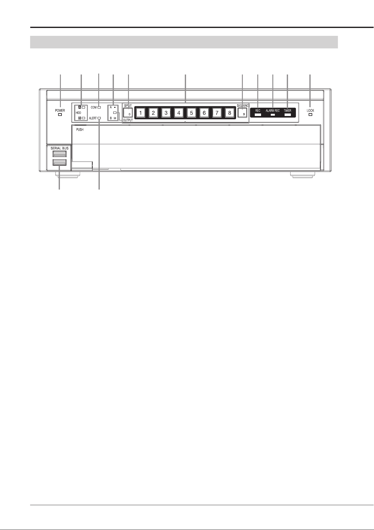
Front view
1 2 3
12
4 5 6 7 8 9 10 11
13
1 POWER indicator
When the POWER button is pressed while the MAIN
switch on the rear of this recorder is ON, this indicator
illuminates. When this recorder is in the standby status
or the MAIN switch on the rear of this recorder is OFF,
this indicator goes out. It takes about 1 to 2 minutes
for this recorder to be ready for operation after the
POWER button is pressed. When this recorder is in the
process of operation transition such as startup, this indicator blinks and other operations are not acceptable.
2 ACCESS indicators (HDD A, HDD B indica-
tors)
This indicator illuminates when this recorder is accessing the internal HDD or externally connected devices.
Before pressing the POWER button, wait until the indicator goes out.
3 COM (COMMUNICATION) indicator
This indicator illuminates when this recorder starts
communicating via LAN.
4 OUTPUT A/B indicator
This indicator goes out when the multiplexer output A
is selected and it illuminates when B is selected.
5 SPLIT button
When this button is pressed, the screen mode changes
to split display mode.
* This illustration shows an example of DX-TL308E
OUTPUT A/B button
When this button is held down for 2 seconds or longer,
the multiplexer output is switched between A and B.
The OUTPUT A/B indicator goes out when A is selected and it illuminates when B is selected. While the
multiplexer output B is selected, the menus are not
displayed.
6 <DX-TL308E> Camera number buttons (1 to 8)
<DX-TL304E> Camera number buttons (1 to 4)
Press these buttons to display images from the cameras connected to this recorder. The number of button
corresponds to that of the CAMERA IN connector on
the rear of this recorder. The button corresponding to
the camera you are viewing illuminates.
Number buttons (0 to 9)
Press these buttons to input passwords.
7 SEQUENCE button
Press this button to automatically switch images from
cameras.
8 REC indicator
This indicator illuminates when this recorder starts recording. It goes out when the recorder stops recording.
9 ALARM REC indicator
This indicator blinks when this recorder starts alarm
recording. It goes out when the recorder stops alarm
recording.
16
Page 17

10 TIMER indicator
This indicator illuminates while this recorder is in the
timer recording mode or timer recording standby mode.
It blinks when an error is found in the timer program.
11 LOCK indicator
This indicator illuminates while the simple lock or the
password lock is enabled.
12 SERIAL BUS ports
Input and output ports to connect a device equipped
with serial bus terminal. Bus power cannot be used.
When the serial bus ports are not in use, attach the
serial bus port covers to keep dust from entering the
recorder.
13 ALERT indicator
This indicator blinks when the recorder notifi es an im-
portant event such as an error occurring in it.
ENGLISH
Beginning
17
Page 18
Major operations and their functions (continued)
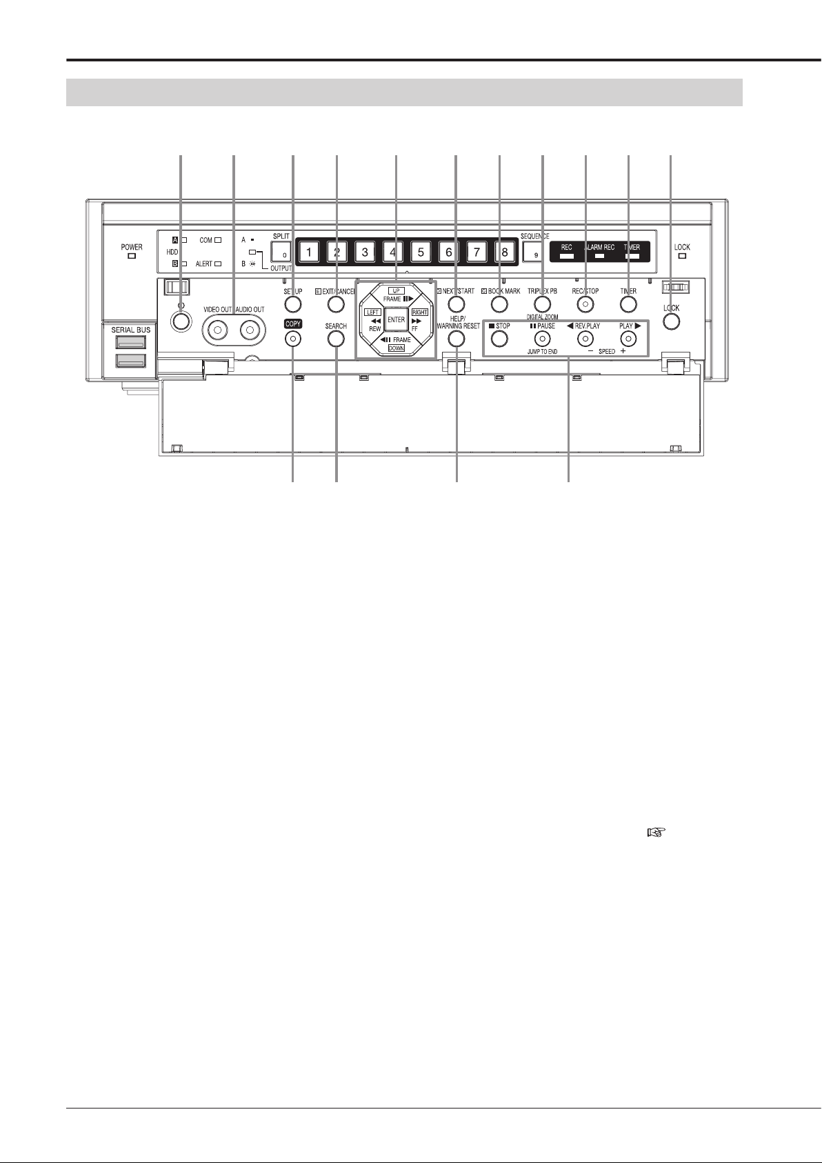
Front view (inside of door)
14 15 16 17 1918 20 21 22 23 24
25 26 27 28
14 POWER button
The power is turned on when this button is pressed
while the MAIN switch on the rear is ON. When this
button is pressed again, this recorder enters the
standby mode. When this recorder is in the process of
operation transition such as startup, the POWER indicator blinks and other operations are not acceptable.
15 Analog output connectors
VIDEO OUT connector
RCA connector to output video signals. The same image as that from OUTPUT A is output.
AUDIO OUTPUT connector
RCA connector to output audio signals.
16 SET UP button
When this button is pressed, <Main menu> is displayed.
17 EXIT/CANCEL button
This button is used to set the menus.
18 Direction buttons (UP, DOWN, LEFT, RIGHT
buttons)
Use these buttons to move the item to be set during
menu setting.
These buttons are also used to move the magnifi cation
center point while enlarging an image.
* This illustration shows an example of DX-TL308E.
REW, FF buttons
Use these buttons to adjust the playback speed, and to
rewind or forward the recorded images.
ENTER button
This button is used to designate the detection target
areas of the motion detection function.
It is also used to accept the menu settings.
19 NEXT/START button
This button is used to set the menus.
20 BOOK MARK button
When this button is pressed, <Bookmark menu> is
displayed. When the playback device is designated
as Copy device, Archive device, or preliminary area,
<Bookmark menu> is not displayed. (
Page 74)
21 TRIPLEX PB button
When this button is pressed while live images from
cameras are being displayed in the split display mode,
the playback image of your desired camera can be displayed. Triplex playback is possible with Output A only.
DIGITAL ZOOM button
When this button is pressed in the single screen display mode or the single screen playback mode, the
displayed image is enlarged. To move the magnifi ca-
tion center point, press the direction buttons.
FRAME buttons
Use these buttons for frame-by-frame playback.
18
Page 19

22 REC/STOP button
When this button is pressed, this recorder starts recording and the REC indicator illuminates. When this
button is held down for 2 seconds or longer, this recorder stops recording and the REC indicator goes out.
When this button is held down for 2 seconds or longer
during alarm recording or emergency recording, this
recorder stops recording. This recorder does not stop
recording during timer recording even when this button
is held down.
23 TIMER button
When this button is pressed, this recorder enters the
timer recording mode or standby mode and the TIMER
indicator illuminates. When this button is held down
for 2 seconds or longer, the timer recording mode or
standby mode is canceled and the TIMER indicator
goes out.
24 LOCK button
When this button is pressed while the MAIN switch on
the rear is ON, this recorder enters the simple lock or
password lock mode. While this recorder is locked,
the indicator illuminates. You can set passwords using
<Password> of <Main menu>. (
Pages 111 to 114)
REV.PLAY button
When this button is pressed, this recorder starts reverse playback and the button illuminates.
PLAY button
When this button is pressed, this recorder starts playback and the button illuminates.
SPEED (+ and -) buttons
When the playback (+) button or reverse playback (-)
button is pressed during playback or reverse playback,
the playback rate is changed.
ENGLISH
25 COPY button
When this button is pressed, <Copy menu> is displayed. Use this button to copy or archive data.
Pages 75 to 78)
(
This button illuminates during copy. It blinks at the start
and end of copy operation.
26 SEARCH button
When this button is pressed, <Search menu> is displayed. Use this button to search images. (
68 to 72)
27 HELP button
When this button is pressed, the help menu showing
information such as cautions on use, operating procedures, and functional descriptions is displayed.
It is also used to display the warning.
WARNING RESET button
When this button is pressed while a warning is displayed, the warning display is cleared.
28 Operation buttons
STOP button
Press this button to stop playback.
PAUSE/JUMP TO END button
When this button is pressed during playback, still image playback starts and the button illuminates. When
this button is pressed again, playback starts and the
button goes out.
When the PAUSE/JUMP TO END button is pressed
while the playback is stopped, images around the end
of the latest recorded data are played back in the still
image playback mode. (End point search)
Pages
Beginning
19
Page 20
Major operations and their functions (continued)
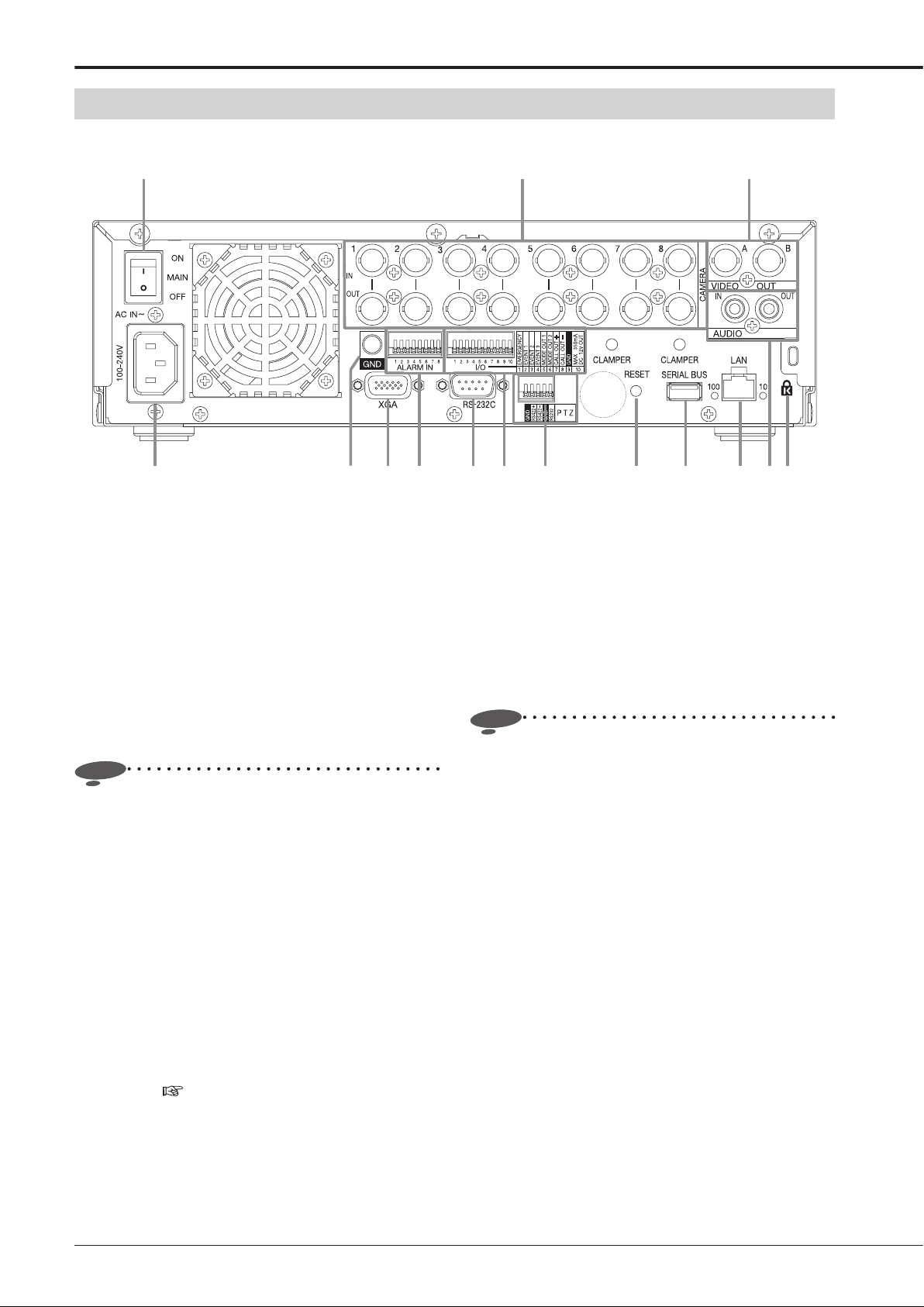
Rear view
1 2 3
4 65 87 9 10 11 12 13 14 15
1 MAIN switch
This is the main power switch. To use this recorder, set
this switch to ON. Otherwise, the POWER button on
the front panel of the recorder cannot turn on or off the
recorder.
2 <DX-TL308E> CAMERA connectors (1 to 8)
<DX-TL304E> CAMERA connectors (1 to 4)
Notice
• Do not connect superimposed voltage cameras
because they can cause damage to the recorder.
CAMERA IN connectors
BNC connectors to input camera video signals.
CAMERA OUT connectors
BNC connectors to output camera video signals.
When the MAIN switch is on, the camera video signals
input to CAMERA IN connectors are looped out to
these connectors.
3 VIDEO OUTPUT connectors
OUTPUT A VIDEO connector
BNC connector to output video signals to the monitor.
OUTPUT B VIDEO connector
BNC connector to output video signals to the second (B)
monitor. (
Page 24)
* This illustration shows an example of DX-TL308E.
4 AC power socket
Use this socket to connect the supplied power cord.
Earth terminal is used for safety. Insert the power cord
of this recorder to the 100 to 240 V outlet with ground
terminal.
Notice
• When the power outlet does not have an earth
terminal, ask your dealer for grounding work (for pay).
Never connect the ground terminal of the power cord
to the gas pipe, water pipe, conductor rod and so on.
• Make sure to use the supplied power cord.
5 GND terminals
This terminal is used as common ground terminal.
6 XGA port (DX-TL308E only)
Port to output video signals to XGA monitor.
7 <DX-TL308E> ALARM IN terminals (1 to 8)
<DX-TL304E> ALARM IN terminals (1 to 4)
Terminals to input alarm signals. These terminals accept alarm signals once a second. However, when
multiple signals are input at the same time, not all the
signals may be accepted.
8 RS-232C connector
This connector is used to connect a host device
equipped with RS-232C connector (such as a personal
computer). This recorder can be controlled from other
devices via this connector.
20
Page 21

9 I/O terminals
EMERGENCY terminal
Input terminal to start emergency recording forcibly.
EVENT terminals (1 to 3)
Input terminals for activate the function confi gured in
the <Event terminal> menu. (
MODE OUT terminals (1 to 2)
Output terminals to notify the current recorder status. Select the status information to be output in the
<Mode-out • Remaining capacity> menu. (
101)
Notice
• The MODE OUT terminal may output a signal for
several seconds when the MAIN switch on the rear
panel of the recorder is turned on or the recorder
recovers from a power failure.
CALL OUT (+) terminal / CALL OUT (-) terminal
Output terminal to notify the trouble in the recorder
and its exclusive ground terminal (isolation terminal).
Information to be externally output consists of items
selectable in the <Warning display • Buzzer • Call-out>
menu (
regardless of the menu settings.
Notice
• The CALL OUT terminal may output a the signal for
several seconds when the MAIN switch on the rear
panel of the recorder is turned on or the recorder
recovers from a power failure. Pay attention to
this matter if you use peripheral devices to issue
notifi cation.
GND terminal
This terminal is used as common ground terminal.
DC 12V OUT terminal
This terminal outputs the direct voltage only when both
the MAIN switch and the POWER button are on. The
maximum electric current is 350 mA.
pages 99 and 100) and items to be output
Page 102)
Page
12 SERIAL BUS ports
Input and output ports to connect a device equipped
with serial bus terminal. Don't use the function to control the powers of external devices using the bus power
of this recorder. Bus power cannot be used.
By connecting various external HDDs to this recorder,
you can expand the memory or use them as a copy
device. However, when you perform recording, playback, or copy at a high rate using this unit, recording
or playback data dropout or other failure may occur
depending on the connected device because of slow
data transfer or slow response. Be sure to check for
such failure before starting the practical operation of
the recorder.
13 LAN port
Port for communication with the special application
software using a web browser.
14 AUDIO connectors
AUDIO IN connector
RCA connector to input audio signals.
AUDIO OUT connector
RCA connector to output audio signals.
15 Keyhole for antitheft lock
This is a hole to connect a commercially available antitheft cable manufactured by Kensington.
ENGLISH
10 PTZ control terminals
These terminals are used to connect a PTZ camera to
control (pan, tilt and zoom) it.
11 RESET button
When this button is pressed, this recorder is reset and
the power is turned off. In this case, image data, menu
settings, and the clock setting are retained.
Beginning
21
Page 22
Major operations and their functions (continued)
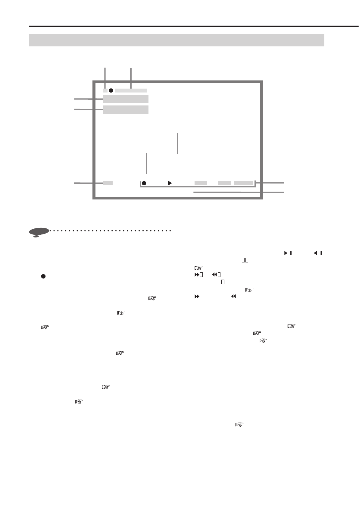
Screen display
1
1
3
4
19-01-2008 Sat
15:00:45
HDD (EMR)
CIF • L3
2
Alarm interrupt
6
Please push the help button
N 69%
5
Notice
• The above fi gure is an example for explanation. Some
items may not be displayed simultaneously.
REM A 29%
1 Camera number/Camera title
A camera number or camera title is displayed.
is displayed on the right side of the camera number
during recording. (When you select to hide the camera
number, it is not displayed.)
For setting the items to be displayed, see
103.
For setting the camera title, see
For setting the camera number display position, see
page 103.
2 Alarm input prohibition
When alarm input is prohibited, this indication appears.
For alarm input prohibition, see
3 Clock
The present time is displayed. The recording time is
displayed during playback.
For setting the clock, see
For setting the display position and display mode of
the clock, see
page 102.
page 99.
Recorder title
N
page
page 103.
page 61.
7
Camera title
4 Playback information
The playback device, picture size, and picture quality
are displayed during playback.
When the playback rate is changed,
FPS is displayed. ( shows the number of frames.)
Page 73
or is displayed during rewind or fast forward
playback. (
the playback speed.)
Hi-speed or Hi-speed is displayed during super
high-speed playback.
The displayed items are different in the single screen
display mode and the split screen display mode.
For switching the playback device, see
For the picture size, see
For the picture quality, see
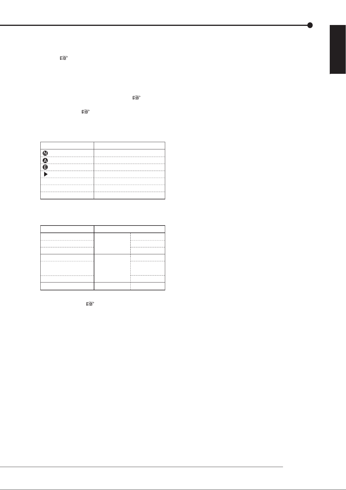
5 Remaining capacity
The remaining capacity of the selected device is displayed. When the remaining capacity of the registered
device decreases to the predetermined level, "REM" is
displayed.
N ..... HDD (Normal)
A ..... HDD (Alarm)
E ..... HDD (Emergency)
AR ... HDD (Archive)
For setting the device to be displayed and the remaining capacity, see
ARCHIVECOPY[B]SYNC[SBM08][SBM08]
8
1
FPS or
shows the number indicating the level of
Page 73
page 66.
page 51.
page 52.
page 101.
22
Page 23
6 Recorder title
The designated recorder title is displayed.
For setting the recorder title and displaying/hiding the
title, see
page 102.
7 Warning
Warning is displayed when a failure or error occurs in
this recorder. Press the HELP button to check the details.
For setting the warning indication, see
and 100.
For warnings, see
pages 128 to 131.
8 Operation status
The current operation mode of this recorder or devices
being operated are displayed.
Indication Operation status
Normal recording
Alarm recording
Emergency recording
Playback
SYNC
COPY
ARCHIVE
(*): The copy destination HDD is displayed during synchronization. (Displayed only when synchronizing with the internal
HDD. When synchronizing with the external HDD, this
indication does not appear.)
Indication Device being operated
[A]
[B]
[SBM01] - [SBM08]
[SBC01]
[SBC17]
[SBC18]
[SBB01] - [SBB08]
Synchronizing (*)
Copying
Archiving
Main recording
device
Copy device
Archive device
Internal HDD A
Internal HDD B
External HDD
External HDD
DVD/CD (in an
external drive)
USB memory
External HDD
ENGLISH
pages 99
For displaying or hiding the operation status and HDD
being operated, see
page 102.
Beginning
23
Page 24
Connections
Camera
<DX-TL308E> (up to 8 cameras)
<DX-TL304E> (up to 4 cameras)
RS232C
integral camera
RS422
integral camera
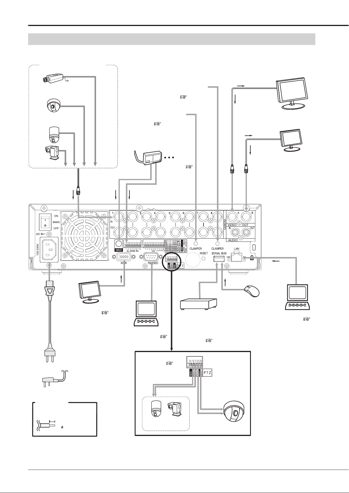
Connecting CCTV cameras, monitors, and sensors
To VI D E O I N
Secure the USB cord using the
supplied clamp band to prevent
disconnection. ( Page 26)
Secure the power cord using the
supplied clamp band to prevent
disconnection. ( Page 26)
connector
To OUTPUT A
VIDEO connector
Monitor
To VIDEO IN
connector
To CAMERA IN
connectors
corresponding to the
camera numbers
XGA (PC) monitor (DX-TL308E only)
Power cord
To GND
terminal
To XG A
port
For setting, see page 105.
sor 1
Sen
For setting, see
pages 53 and 54.
To ALARM IN terminals
corresponding to the
sensor numbers
PC
For setting, see
page 108.
To SERIAL
BUS port
External recording device
DX-ZD6UE
Up to 4 to 8 devices can be used at the
same time. (The number of devices differs
depending on the operation manner.)
For setting, see page 36.
To OUTPUT B
VIDEO connector
* This illustration
shows an example
of DX-TL308E.
To LAN port
Mouse
Monitor
For setting, see
pages 108 and 109.
PC
24
for the Continent
for U.K
<Cable termination>
Cable end connected to ALARM IN
or I/O terminal and RS422
5-7 mm strip-off
Applicable wire
0.32-0.65 mm
(AWG 28-22)
PTZ control terminals
For setting, see
page 110.
RS232C
integral camera
RS422
integral camera
Page 25
Notice
• By connecting various devices, you can control this recorder by external devices and control external devices by this
recorder. However, depending on the operating condition of the recorder, its operation and control of external devices
may become slow or unstable.
• Select a USB hub supporting USB 2.0. Depending on the type of the USB hub you use, when a USB 2.0 device and a
USB 1.1 device are connected, both of them may operate according to the USB 1.1 standard. Avoid using such USB
hub.
• Before connecting external devices, turn off the MAIN switch of the recorder. After the completion of connection, turn on
the powers of the external devices fi rst and then turn on the MAIN switch of the recorder.
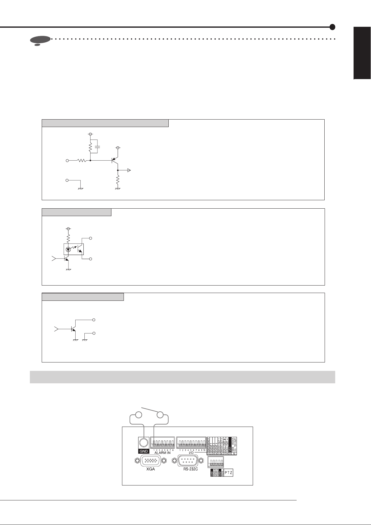
EMERGENCY/ALARM IN/EVENT 1-3 input terminals
[Input circuit]
Input
terminal
10kΩ
22kΩ
5V
0.047µF
5V
[Input conditions] Grounding for 200 ms or longer
[Input interval] At least 1 second
[Specifications] When operating: Short-circuited to GND terminal or L-level
voltage is applied.
When not operating: Open
ENGLISH
GND
<Recorder's internal circuit>
CALL OUT output terminal
[Output circuit]
<Recorder's internal circuit>
MODE OUT 1-2 output terminals
[Output circuit]
<Recorder's internal circuit>
4.7kΩ
CALL OUT (+) terminal
CALL OUT (-) terminal
Output terminal
GND
[Specifications] Warning alarm signal (Photocoupler output)
When operating: Short
Max. allowable input current is 7 mA DC.
When not operating: Open
Max. allowable input voltage is +24 V DC.
* The terminal may output a signal for several seconds when the MAIN switch on
the rear panel of the recorder is turned on or the recorder recovers from a
power failure.
[Specifications] When operating: L-level voltage is output.
Max. allowable input current is 7 mA DC.
When not operating: Open
Max. allowable input voltage is +24 V DC.
* Use the recorder within the ratings shown above.
* The terminal may output a signal for several seconds when the MAIN switch on
the rear panel of the recorder is turned on or the recorder recovers from a
power failure.
Connection for alarm recording
Following fi gure shows an example of the connection of alarm signal corresponding to alarm sensor 1.
Alarm switch
* This illustration shows an example of DX-TL308E.
Connections
25
Page 26
Connections (continued)
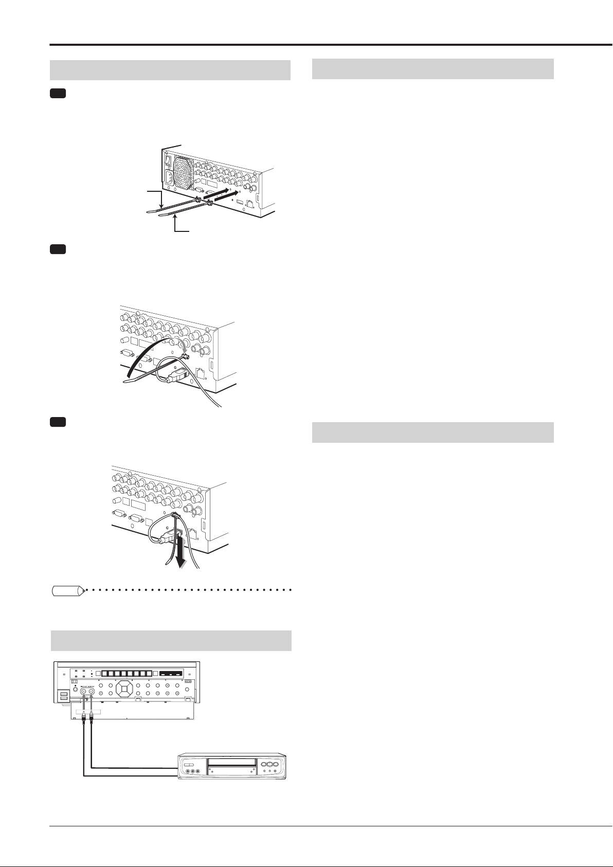
Cable clamping
Step
1 Insert the supplied clamp bands into the clamp
holes in the rear of the recorder.
•
One clamp hole is for the power cable and the other
is for USB cables.
For power cable
For USB cable
Step
2 Run the cable to be clamped around the clamp
band as shown in the fi gure.
•
The rough side of the band should face up.
Optional products
DX-ZD6UE
DX-ZD5UE(Z)
Additional hard disk unit (for serial bus connection)
By connecting various external HDDs to this unit, you
can expand the memory or use them as a copy device.
However, when you perform recording, playback, or copy
at a high rate using this unit, recording or playback data
dropout or other failure may occur depending on the
connected device because of slow data transfer or slow
response. Be sure to check for such failure before starting
the practical operation of the recorder.
Don't use the function to control the powers of external
devices using the bus power of this recorder.
When using DX-ZD6UE, you can use the mirroring and
spanning functions.
DX-RM5(ZD)
Rack-mount adapter for additional hard disk unit DXZD6UE/DX-ZD5UE(Z)
DX-KB5UE
Keyboard for digital recorder
Step
3 Pull the end of the clamp band until it is
tightened.
Tips
• Illustrations show an example of DX-TL308E.
Connecting an analog VCR
DX-RM3
Rack-mount adapter for digital recorder DX-TL308E/DXTL304E series
Recommended products
For recommended external devices, contact your dealer.
External devices you want to use may not be suitable for
the intended application of this recorder. For details, you are
recommended to contact your dealer.
By connecting various external HDDs to this recorder, you
can expand the memory or use them as a copy device.
However, when you perform recording, playback, or copy
at a high rate using this unit, recording or playback data
dropout or other failure may occur depending on the
connected device because of slow data transfer or slow
response. Be sure to check for such failure before starting
the practical operation of the recorder.
26
To VIDEO OUT
connector
To AUDIO OUT
connector
Audio cable
(commercially available)
Video cable
(commercially available)
To AUDIO IN
connector
To VIDEO IN
connector
Analog VCR
Page 27
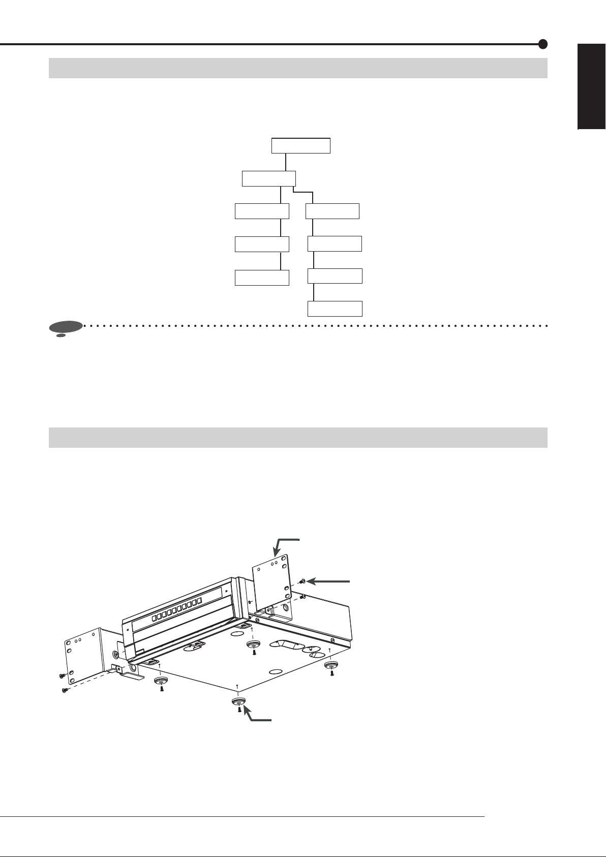
Caution for connecting additional hard disk units
When you connect 5 or more additional hard disk units to this recorder, you are recommended to connect them by USB
cables as shown below in order to prevent recognition failure caused by variation in their startup time.
At the commencement of practical operation, check that they are recognized correctly even when a small number of units are
connected.
Recorder
IN
Additional
unit
OUT
IN
Additional
unit
OUT
IN
Additional
unit
OUT
IN
Additional
unit
Notice
• When you play back data stored in the extension unit during recording to the same extension unit at a rate close to
the recorder’s maximum processing capacity (for example of DX-TL308E, at 12.5 FPS for all the cameras in the 2CIF
picture size), noise may appear in the image or audio. In addition, when you make backups of the data to the extension
unit during recording on the recorder, make sure to set the total recording rate of cameras to half or less of the upper
limit of the designated picture size (<DX-TL308E> 4CIF: 25 FPS or less, 2CIF: 50 FPS or less, or CIF: 100 FPS or less,
<DX-TL304E> 4CIF: 12.5 FPS or less, 2CIF: 25 FPS or less, or CIF: 50 FPS or less).
IN
Additional
OUT
IN
Additional
OUT
IN
Additional
OUT
IN
Additional
unit
unit
unit
unit
ENGLISH
Caution in installing multiple recorders in an EIA rack
Follow the steps below to install the recorder in an EIA rack (occupying 2U space) using the rack mount adaptor (DX-RM3).
1 Remove the feet from the bottom of the recorder. (4 feet)
2 Fit the rack mount adaptor using the screws on both sides of the recorder. (2 screws on each side)
3 Secure the recorder to the EIA rack using screws.
Prepare appropriate screws for your rack.
Rack mount adaptor (DX-RM3)
Screws on the recorder (2 screws on each side)
Feet on the bottom of the recorder (4 feet)
Connections
27
Page 28
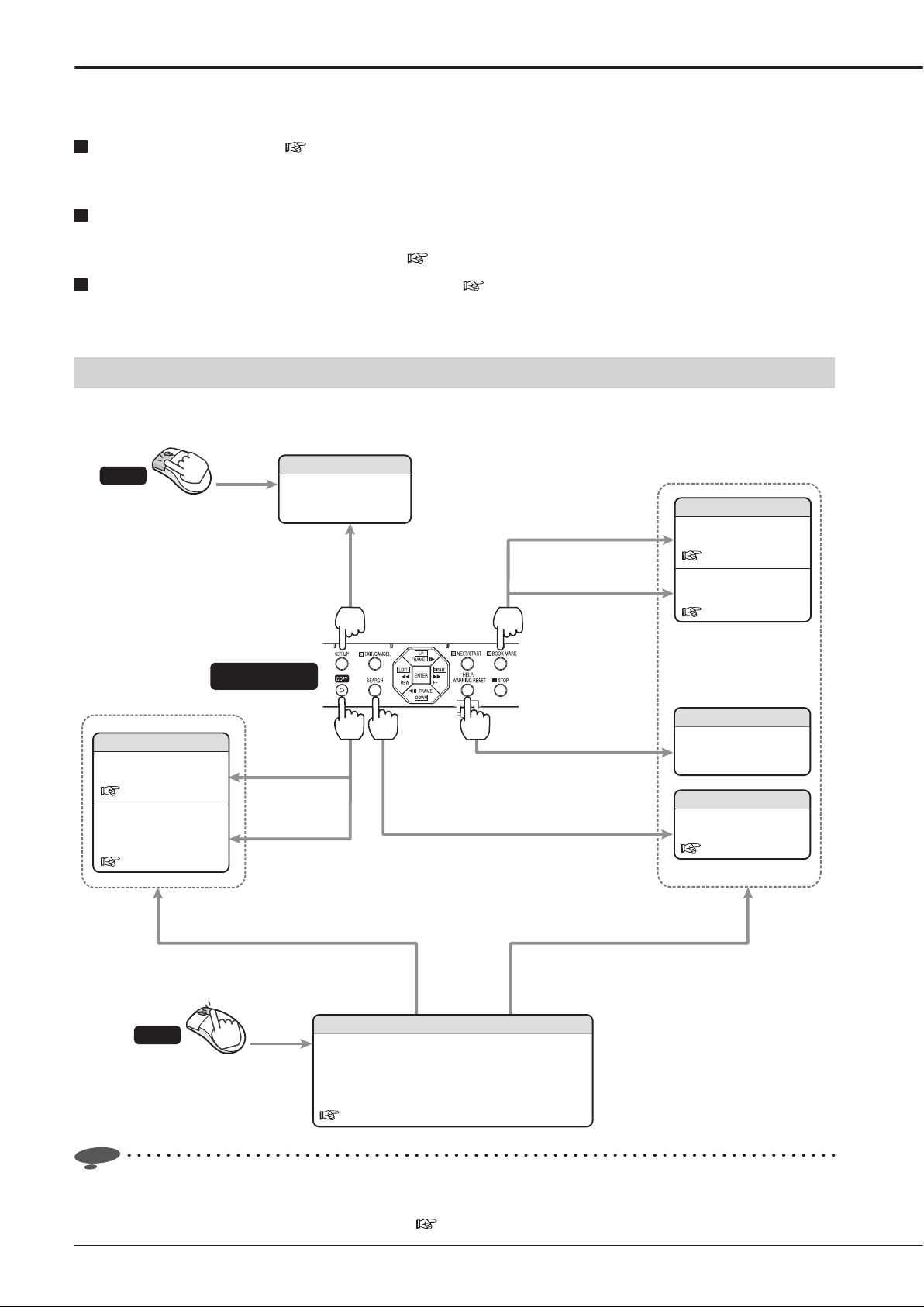
How to set the menus
You can set the operation conditions and perform various controls using the menus.
There are 3 methods to set the menus as described below.
Set the menus automatically ( Pages 32 and 33)
When you turn on the recorder for the fi rst time, the Setup Wizard screen is displayed and you can confi gure the minimum
required settings according to the displayed menus.
Set the menus manually
You can manually change the settings made by the Setup Wizard or manually confi gure settings other than those made by
the Setup Wizard. For how to locate setting items, see
Copy the menu settings of other DX-TL308E/DX-TL304E ( Page 107)
You can set the recorder's menus by copying the menu settings of other DX-TL308E/DX-TL304E to externally connected
media and then loading those settings.
Displaying the menus
When you press the following buttons, the corresponding menus are displayed. (Check that no other menus or warnings are
displayed.)
page 2.
Mouse
Copy menu
You can copy data for a
short time of period.
Page 75
You can copy or archive
data based on the
conditions you specify.
Pages 75 to 78.
Left-click
Inside the front
door of the recorder
You can set the
operation conditions of
the recorder.
Press while the
single screen
playback is in pause.
Main menu
Press while the single screen
playback is in pause.
Bookmark menu
You can register
bookmarks.
Page 74
You can search for
bookmarked images.
Page 74
Help menu
Detailed descriptions of
the menus and warnings
are displayed.
Search menu
You can search for
desired images.
Pages 68 to 72.
Notice
Mouse
You can display these menus also
from the mouse operation screen.
Right-click
You can operate various functions of the recorder
using a mouse.
You can display the Search menu, Copy menu,
Bookmark menu, and Help menu also from the
mouse operation screen.
Pages 30 and 31.
Mouse operation screen
You can display these menus also
from the mouse operation screen.
• When the multiplexer Output B is selected, menus cannot be displayed. In addition, when you operate the recorder by
a mouse, the mouse cursor is displayed but no menus are displayed and you cannot confi gure the menu settings. You
can set the menus only when Output A is selected. (
Page 41)
28
Page 29
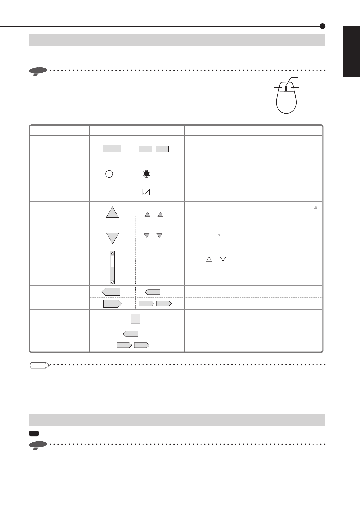
Operating the menus
You can operate the displayed menu by pressing the buttons on the front panel of the recorder or clicking the buttons
displayed on the menu screens.
Notice
• Use a general USB mouse having two buttons as shown by the fi gure. Certain types
of mouse cannot be used with this recorder.
You are recommended to use a mouse having 800 dpi resolution.
• Mouse is not supplied with the recorder.
• Mouse wheel doesn’t work with this recorder.
Mouse
Wheel
Right buttonLeft button
ENGLISH
To set parameters.
To switch the selected
item in the list.
To display
other menus.
To display the
Help menu.
To accept the
menu settings.
Buttons on the screen
(Disabled)
?
E:Return
D:Next Setting
Examples
1 High
(Enabled)(Disabled)
(Enabled)
10
100
10 100
E:Return
, etc
D:Next Setting
, etc
, etc
, etc
Descriptions
When you click on the button, the parameter or number
displayed on the button changes. Left-click or right-click
, etc
repeatedly until the desired item is displayed.
Click the radio button of the desired parameter.
Select the checkbox of the desired parameter to put a
checkmark.
You can go to the next item. For example, by pressing the [ ]
button, you can skip next 10 items.
In addition, this button is used to change the setting values.
You can go back to the previous item. For example, by
pressing the [ ] button, you can skip back previous 10 items.
In addition, this button is used to change the setting values.
You can scroll lists.
Click on or .
You cannot scroll lists using the buttons on the front panel of
the recorder.
The previous menu is displayed.
The next menu is displayed.
, etc
Help menu is displayed, showing information such as
operation procedures. This menu is also displayed when you
press the HELP button on the front panel of the recorder.
When you set a desired item and then display other menu by
[Return] or [Next], the setting you made is determined.
10
10
Tips
• To set the menus using the buttons on the front panel of the recorder
You can select a setting item using the direction buttons and determine the setting using the ENTER button.
Instead of the buttons showing letter C, D, or E, such as [D:Next], displayed on the screen, you can use the button C, D,
or E on the front panel of the recorder.
Closing the menus
Step
1 Display the Main, Search, Copy, or Bookmark menu and left-click the [Exit] button.
Notice
• You cannot close the menus by pressing the SET UP button on the recorder.
Menu settings/Device registration
29
Page 30
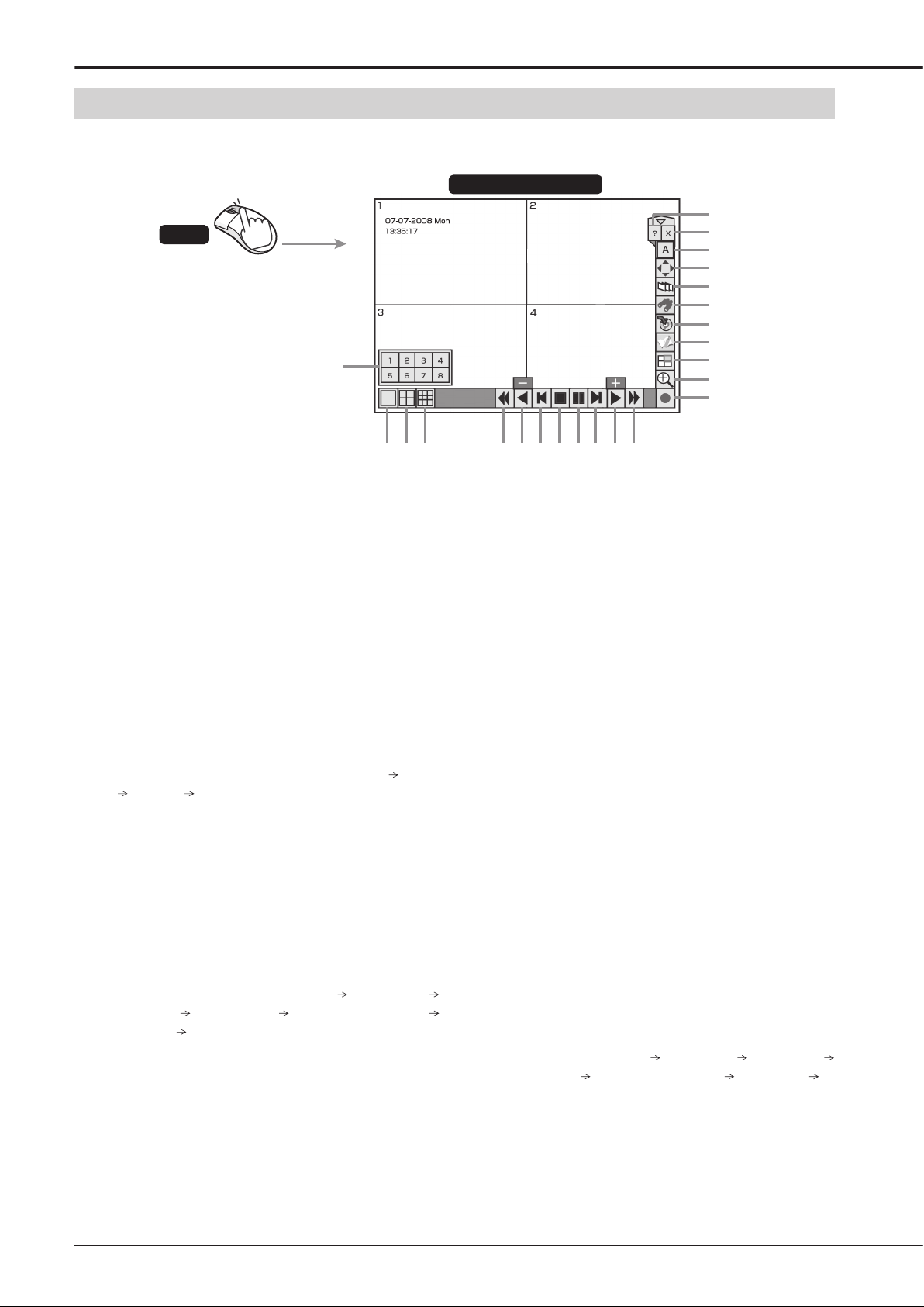
How to set the menus (continued)
Using the mouse operation screen
When you right-click the mouse, the mouse operation screen is displayed and you can control the recorder on the screen.
Mouse operation screen
23
Mouse
Right-click
1
22
21
20
19
18
17
16
15
14
13
* This illustration shows an example of DX-TL308E.
1 Camera number buttons
When you click any of these buttons, the image from
the corresponding camera is displayed on the entire
screen. These buttons are used in the triplex playback
mode, too. While the camera number buttons are displayed, the other buttons don't work.
2 Single screen button
When you click this button, the camera number buttons are displayed for 3 seconds.
3 4-split button
<DX-TL308E> Each time you click this button, the
screen mode changes in the order of 4-split a
4-split a ...
b
<DX-TL304E> When you click this button, a 4-split
screen is displayed.
4 9-split button
<DX-TL308E> When you click this button, a 9-split
screen is displayed.
<DX-TL304E> Not available.
5 Reverse search button
Each time you click this button during reverse playback, the button illuminates and the playback speed
changes in the order of approx. X2
approx. X8
approx. X2
approx. X16 high-speed playback
...
approx. X4
6 Reverse play button
When you click this button, reverse playback starts.
When you click the button during playback or reverse
playback, images are played or reverse-played at the
lowest rate and [-] is displayed on the button. Each
time you click the [Play] button while [-] is displayed,
the playback speed increases.
2 3 4 7 8 9 10 11 12
5 6
7 Reverse step button
When you click this button, reverse frame-by-frame
playback starts.
8 Stop button
When you click this button, playback stops.
9 Pause button
When you click this button during playback, the still
image playback mode starts. By clicking this button
again, playback resumes.
When this button is pressed while the playback is
stopped, images around the end of the latest recorded
4-split
data are played back in the still image playback mode.
10 Step button
When you click this button, frame-by-frame playback
starts.
11 Play button
When you click this button, playback starts.
When you click the button during playback or reverse
playback, images are played or reverse-played at the
highest rate and [+] is displayed on the button. Each
time you click the [Reverse play] button while [+] is
displayed, the playback speed decreases.
12 Forward search button
Each time you click this button during playback, the
button illuminates and the playback speed changes in
the order of approx. X2
approx. X16
high-speed playback approx. X2 ...
13 Recording/Stop button
When you click this button, recording starts and the
button illuminates. By clicking this button again, a confi rmation screen is displayed. When you select [Yes],
recording stops and the button goes out.
approx. X4 approx. X8
30
Page 31

14 Zoom button
When you click this button during single screen display
or single screen playback, the displayed image is enlarged. Each time you click this button, the magnifi ca-
tion changed in the order of X1
display. You cannot enlarge the image output from
Output B using the mouse operation screen.
To move the magnifi cation center point, click the shad-
ed areas shown below.
X2 X4 normal
15 Triplex PB button
When you click this button while live image is displayed in the split display mode, the triplex playback
mode is activated and the camera number buttons are
displayed for 3 seconds. When you click any camera
number button, the playback image of the corresponding camera is displayed. For notes for using the triplex
playback mode, see
page 42.
16 Bookmark button
When you click this button, the mouse operation
screen is closed and the <Bookmark menu> is displayed. When the playback device is designated as
Copy device, Archive device, or preliminary area, the
<Bookmark menu> is not displayed. (
Page 74)
17 Copy button
When you click this button, the mouse operation
screen is closed and the <Copy menu> is displayed.
Use this button to copy or archive data. (
to 78)
18 Search button
When you click this button, the mouse operation
screen is closed and the <Search menu> is displayed.
Use this button to search images. (
Pages 68 to 72)
19 Sequence button
When you click this button, the sequential display
screen is displayed and the button illuminates. By
clicking the button again, the sequential display is canceled.
20 PTZ button
When you click this button while live images are displayed, the recorder enters the PTZ mode. For operations in the PTZ mode, see
page 43.
21 Output A/B button
When you click this button, the multiplexer output is
switched between A and B. Each time you click this
button, the multiplexer-related buttons are switched
between two monitors connected to the OUTPUT A
connector and OUTPUT B connector.
When Output B is selected, only the buttons for controlling the multiplexer are displayed.
Pages 75
22 Exit button
When you click this button, the mouse operation
screen is closed.
23 Help button
When you click the button, the Help menu is displayed.
Notice
• When you click the button, the hidden buttons
are displayed. To hide the buttons being displayed,
click the
• When the password lock is enabled, you can use the
buttons for unlocked operations only. (
to 114)
• The mouse operation screen automatically disappears
when you don’t operate the mouse for 1 minute.
• You cannot display warnings by pressing the HELP
button when they occur while the mouse operation
screen is displayed. Close the mouse operation screen
fi rst.
• In forward search/reverse search, the intended
playback speed may not be obtained when a heavy
load is imposed on the recorder or when the highspeed data transmission is unavailable due to the
use of an external DVD/CD drive, USB memory, or
external HDD.
button.
Pages 111
ENGLISH
Menu settings/Device registration
31
Page 32

Using the Setup Wizard
Making the minimum required settings
automatically
<Setup Wizard>
Step
2 Select whether or not to use the Setup Wizard.
•
Select [Next] when using the Setup Wizard and [Quit]
when not. When you select [Quit], the clock starts
from the initial setting.
When you turn on the power of the recorder for the first
time, the Setup Wizard screen is displayed for making the
minimum required settings.
Tips
• The Setup Wizard screen is automatically displayed
only when you first turn on the power. It is not
displayed from the next turn-on.
Turn on the power for the first time.
Select whether or not to use the Setup Wizard.
Language selection
Time/date adjust
HDD configuration
Recording setup
Step 1 Camera check
Step 2 Define the normal recording cycle
Step 3 Confirm the recording settings
Finish
Step
Step
Step
Step
Step
Step
Step
Step
Step
Step
1
2
3
4
5
6
7
8
9
10
Tips
• When you want to cancel the Setup Wizard in
midstream, cancel it according to the instructions
displayed on the screen. You can cancel the Setup
Wizard in step 6. In this case, the settings you made in
steps 1 to 5 remain effective.
Step
3 (When you select [Next])
Select a language.
•
The <Language selection> screen is displayed.
Select a language used for the menus.
•
Select a language and then [Next].
Step
4-1 Set the current time and select [Set].
Step
4-2 Select [Setting] and set the time zone depending
on the location of the recorder, and then select
[Set].
•
After fi nishing the setting, select [Return] to return to
the screen of step 4-1 and then [Next].
Tips
• When you select [Set], the clock starts.
Step
5 Set the HDD confi guration.
•
When you select [Register], all the connected HDDs
are automatically registered as Main device.
When the registration fi nishes, a confi rmation screen
is displayed. Check the settings and select [Next].
•
For setting Copy device and Archive device, see
pages 34 to 37.
•
For mirroring setting, see page 35.
•
For partition setting, see page 39.
Step
1 After connecting cameras and monitors, turn
on the MAIN switch on the rear of the recorder.
Check that the POWER indicator goes out and
then press the POWER button on the front panel
of the recorder.
•
The <Setup Wizard> screen is displayed.
Notice
• While the POWER indicator is blinking, the POWER
button does not work. When you turn on the MAIN
switch of the rear panel of the recorder, wait for more
than 5 seconds after the indicator goes out before
pressing the POWER button.
Step
6 Select whether or not to make recording settings.
•
Select [Next] when you make recording settings and
[Quit] when not.
Step
7 (When you select [Next])
When you select [Execute], the recorder
automatically detects the active cameras and
displays their numbers.
•
When the recorder fi nishes detecting the cameras,
select [Next].
•
The detection results are applied to Recording A-D,
emergency recording, and single sequential display.
Step
8 Set the recording cycle and recording hours per
day.
•
After fi nishing the setting, select [Next].
32
Page 33

Step
9 Picture quality and FPS are automatically
set for the cameras detected in step 7 and a
confi rmation screen is displayed.
•
The picture quality and FPS are same among all
the cameras detected in step 7. The settings made
in this step are applied to normal recording of
Recording A.
•
Picture size is set to 4CIF (frame mode). ( Page
51)
•
For how to make recording settings manually, see
pages 51 to 54.
•
Check the confi rmation screen and select [Next].
Tips
• Audio is not recorded by default. For how to record
audio, see
page 60.
When you enable audio recording, the recording cycle
becomes shorter than that when not recording audio.
Check the estimated recording time in the Recording
setting menu. (
Page 53)
• The estimated recording time is based on 24-hour
recording per day.
Step
10 Select [Finish] to exit the Setup Wizard.
•
The recorder becomes ready for operation.
ENGLISH
Menu settings/Device registration
33
Page 34

Registering the devices
Setting Main, Copy, and Archive devices
You can assign the HDDs to Main, Copy, and Archive
devices.
Device
Main
device
Copy
device
Archive
device
Not
assigned
Notice
• You cannot register devices during access to the
HDD such as recording and playback. In addition, you
cannot start recording or playback during registration.
• Devices that can be set as Copy device are serial bus
HDD, DVD/CD drive (external), and USB memory.
With this recorder, up to 4 GB USB memory devices
are usable. USB memory devices with 128 MB or less
capacity are not supported.
Device that can be set as Archive device is serial bus
HDD.
• Up to 10 devices including DVD/CD drive and USB
memory can be connected to the serial bus. This is
the total number of Main, Copy, and Archive devices.
• Up to 10 HDDs including internal HDDs can be used
as Main device. (This is the total number of internal
HDDs and serial bus HDDs.)
• Space totaling 22 GB of the internal HDDs is assigned
to the preliminary recording area. (11 GB each from
Internal A and B) This space is so assigned even when
the preliminary recording is disabled.
Application Usable device
Used as the
recording destination
of normal recording,
alarm recording, and
emergency recording.
Used as the copy
destination.
Used as the archive
destination.
Not used for recording.
Internal HDD
External HDD
External HDD
DVD/CD (in an
external drive)
USB memory
External HDD
<HDD registration>
Device name
[A], [B]
[SBM01] - [SBM08]
[SBC01]
[SBC17]
[SBC18]
[SBB01] - [SBB08]
Cautions for using external devices
By connecting various external HDDs to this recorder, you
can expand the memory or use them as a copy device.
However, when you perform recording, playback, or copy
at a high rate using this unit, recording or playback data
dropout or other failure may occur depending on the
connected device because of slow data transfer or slow
response. Be sure to check for such failure before starting
the practical operation of the recorder.
Don't use the function to control the powers of external
devices using the bus power of this recorder.
Hookup and operation setting of HDDs
When you connect an HDD to the SERIAL BUS port of the
recorder, use a USB 2.0 cable.
Turn off the MAIN switch before connecting the HDD. After
the completion of connection, turn on the powers of the
external devices fi rst and then turn on the MAIN switch of
the recorder.
The connected HDD is recognized at the time of startup.
Order of recording and playback of the internal and
external HDDs registered as Main device
Recording and playback are carried out on the internal
HDDs in the following order:
Internal A
Internal B
When recording or playback on the internal HDDs is
completed, it is carried on to the HDDs connected to the
SERIAL BUS port. Recording is carried out in the order of
number contained in the device name "SBM
," 01 to 08.
When recording or playback on the serial bus HDDs is
completed, it is carried on to the internal HDDs.
34
Page 35
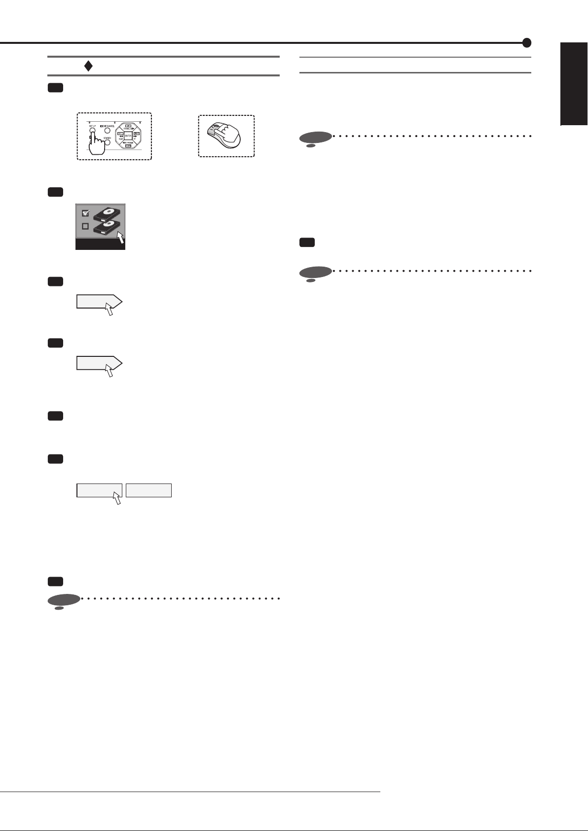
Registering the internal HDDs
Mirroring
Step
1 Press the SET UP button on the front panel of
the recorder or left-click the mouse.
•
<Main menu> is displayed.
Step
2 Select [HDD registration].
or
HDD registration
•
<HDD registration> screen is displayed.
Step
3 Select [Setting] next to [HDD registration].
Setting
•
<HDD registration> screen is displayed.
Step
4 Select [Setting] next to [Register internal HDD].
Setting
•
<HDD registration Internal HDD> screen is
displayed.
Step
5 Check that the internal HDDs are listed on the
<HDD registration Internal HDD> screen.
•
A and B represent the internal HDD numbers.
Step
6 Select whether or not to register the internal
HDDs as Main device.
Main Set
[Main]: HDD is registered as Main device.
[Not assigned]: HDD is not registered as Main
device.
•
Every time you press the button, the button's function
changes between [Main] and [Not assigned].
By recording the same data on 2 HDDs that have the same
capacity, you can reduce the risk of losing recorded data
in the event of sudden crash of Main device. As the same
data are recorded on 2 HDDs, the recordable time is halved.
Notice
• Before changing the HDD operation settings (such as
turning the mirroring ON from OFF or OFF from ON
and changing the partition settings), set the pre-alarm
time of the alarm and emergency recording settings to
0 second. After setting the pre-alarm time to 0 second,
check that the ACCESS indicator goes out and then
change the HDD operation settings.
Step
1 Put a checkmark in the box of [Activate the
mirroring mode].
Notice
• When you enable the mirroring function with the
recorded data stored in the HDD, the recorded data
are deleted.
• You can enable the mirroring function of this recorder
only when both of the internal HDDs A and B are set
as [Main].
• The mirroring function of this recorder can be used
with the internal HDDs only. To mirror data on external
HDDs, use a device having the mirroring function and
refer to the operation manual of the device to be used.
• In case of a failure in either HDD during mirroring, the
recorder continues recording on the normal HDD only.
When you replace the failed HDD, the data are
automatically copied to the newly mounted HDD
and they recover to the status before the failure.
(Data synchronization) When the synchronization is
interrupted by power-off, it resumes when the power is
turned back on.
• Preliminary recording is not performed while the
operation settings of normal, mirroring, or partition are
being changed.
ENGLISH
Step
7 Select [Set] to determine your settings.
Notice
• When no HDD is registered as Main device, you
cannot use a USB memory.
Menu settings/Device registration
35
Page 36

Registering the devices (continued)
Registering external HDDs
Step
1 Press the SET UP button on the front panel of
the recorder or left-click the mouse.
•
<Main menu> is displayed.
Step
2 Select [HDD registration].
HDD registration
•
<HDD registration> screen is displayed.
Step
3 Select [Setting] next to [HDD registration].
Setting
•
<HDD registration> screen is displayed.
Step
4 Select [Setting] next to [Register external HDD].
or
Notice
• Data to be archived are transferred in 2 MB units. At
the end of archive, the data of the latest recording
point may not be completely transferred yet. Pay
attention to this matter when you change the archive
source device.
• The registered information may not be displayed
correctly during recording or playback.
Setting
•
<HDD registration External HDD> screen is
displayed.
Step
5 Check that the HDDs connected to the SERIAL
BUS port of the recorder are listed on the <HDD
registration External HDD> screen.
•
When you select [Check], the ACCESS indicator of
the selected HDD illuminates and you can check the
selected HDD.
Step
6 Select whether or not to register the HDDs
connected to the SERIAL BUS port as Main,
Copy, or Archive device.
Copy SBC01 Set
[Main]: HDD is registered as Main device.
[Copy]: HDD is registered as Copy device.
[Archive]: HDD is registered as Archive device.
[Not assigned]: HDD is not registered as Main,
Copy or Archive device.
•
Every time you press the button, the button's function
changes among [Main], [Copy], [Archive], and [Not
assigned] in order.
36
Step
7 Set the order of recording on the registered
HDDs connected to the SERIAL BUS port.
•
[SBM ] ............. Represents Main device.
[SBC01] .............. Represents Copy device.
[SBB
Set the number shown in
] ............. Represents Archive device.
from 01 to 08. Data are
saved in HDDs in the order of numbers you set.
Step
8 Select [Set] to determine your settings.
Page 37

Checking the registered devices
Step
1 Press the SET UP button on the front panel of
the recorder or left-click the mouse.
ENGLISH
•
<Main menu> is displayed.
Step
2 Select [HDD registration].
or
HDD registration
•
<HDD registration> screen is displayed.
Step
3 Select [Setting] next to [HDD registration].
Setting
•
<HDD registration> screen is displayed.
Step
4 Select [Confi rm] of the device you want to check
under [Check the registered HDDs].
Confirm
•
The HDDs registered as the selected device are
listed. Regardless of the order of registration,
devices are displayed in the order of recording.
•
When you press the button of the device name, the
ACCESS indicator of the selected HDD illuminates
and you can check the selected HDD.
Menu settings/Device registration
37
Page 38

Registering the devices (continued)
Setting the repeat recording and
partition of Main device
Notice
• You cannot make settings during access to the HDD
such as recording and playback. In addition, you
cannot start recording or playback during setting.
Setting the repeat recording
You can set the recorder's operation performed when the
available space in Main device runs out during recording.
Step
1 Press the SET UP button on the front panel of
the recorder or left-click the mouse.
•
<Main menu> is displayed.
Step
2 Select [HDD registration].
<Main HDD setting>
or
Notice
• The repeat recording in the partitioned areas can be
enabled only when the corresponding areas are set in
the <Partition setting>.
• When a warning is issued, "Please push the help
button" is displayed on the screen. The recorder keeps
the latest 16 warnings. The warnings issued before
them are reset and not displayed.
• When the repeat recording is disabled in the alarm
recording area or emergency recording area and
their available space runs out, the alarm recording
or emergency recording stops. When an alarm or
emergency signal is input after that, the indicator
illuminates for a moment but recording is not
performed. (You may not notice that the indicator
illuminates.) In this case, enable the repeat recording
or delete the recorded data to resume recording.
HDD registration
•
<HDD registration> screen is displayed.
Step
3 Select [Setting] next to [Main HDD setting].
Setting
•
<Main device setting> screen is displayed.
Step
4 Select whether to enable or not the repeat
recording in each area.
•
To enable the repeat recording, put a checkmark in
the box.
[Enable]: Automatically returns to the start of the
HDD and resumes recording (overwriting).
[Disable]: Stops recording at the end of the HDD.
When [Warning] of [Remain] on the <Warning
display • Buzzer • Call-out 1> screen (
page 99)
is selected, recording resumes as the warning is
cleared.
When [Warning] of [Remain] on the <Warning
display • Buzzer • Call-out 1> screen (
page 99)
is unselected, recording resumes as the recorded
data are deleted or the repeat recording is enabled.
38
Page 39

Setting the partition
You can partition the Main device.
Partition setting Data to be recorded
No partition
Allocate alarm
recording area
Normal
recording area
Normal
recording area
Alarm recording area
Normal recording
Alarm recording
Emergency recording
Normal recording
Alarm recording
Emergency recording
Step
4 Select [Setting] next to [Change partition setting].
Setting
•
<Partition setting> screen is displayed.
Step
5 Create partitions in the Main device.
•
Set the capacities of the normal recording area,
alarm recording, area and emergency recording
area.
•
When you allocate the alarm recording area and
emergency recording area, the specified space
in the HDDs set as Main device is divided to be
used for alarm recording and emergency recording
independently.
Notice
ENGLISH
Allocate emergency
recording area
Allocate alarm
recording area and
emergency recording
area
Normal
recording area
Emergency
recording area
Normal recording area
Alarm recording area
Emergency
recording area
Normal recording
Alarm recording
Emergency recording
Normal recording
Alarm recording
Emergency recording
Notice
• Before changing the HDD operation settings (such as
turning the mirroring ON from OFF or OFF from ON
and changing the partition settings), set the pre-alarm
time of the alarm and emergency recording settings to
0 second. After setting the pre-alarm time to 0 second,
check that the ACCESS indicator goes out and then
change the HDD operation settings.
Step
1 Press the SET UP button on the front panel of
the recorder or left-click the mouse.
or
• When you create partitions, mirroring cannot be used.
• Functions such as playback, search, information
display, remaining capacity setting (mode-out/call-out)
and deletion of recorded data can be individually set
in each of the normal recording area, alarm recording
area, and emergency recording area.
• When you copy or archive recorded data, you can
select any of the normal recording area, alarm
recording area, and emergency recording area as
copy source.
• Preliminary recording is not performed while the
operation settings of normal, mirroring, or partition are
being changed.
Tips
• When the sum of capacities of the normal recording
area, alarm recording area, and emergency recording
area is 100%, you cannot increase the capacity any
more.
• You cannot set the normal recording area to 0%.
• The recording area for preliminary recording is
assigned in addition to the partitions you can set.
This space is assigned even when the preliminary
recording is disabled.
•
<Main menu> is displayed.
Step
2 Select [HDD registration].
HDD registration
•
<HDD registration> screen is displayed.
Step
3 Select [Setting] next to [Main HDD setting].
Setting
•
<Main device setting> screen is displayed.
Menu settings/Device registration
39
Page 40

Viewing images captured by the cameras
Multiplexer function
<DX-TL308E> You can display images captured by the
connected cameras on 4-split or 9-split screen.
<DX-TL304E> You can display images captured by the
connected cameras on 4-split screen.
In addition, you can arrange the positions of the displayed
images on the screen.
SPLIT/OUTPUT A/B button
Camera number buttons
SEQUENCE button
DIGITAL ZOOM button
Direction buttons
* This illustration shows an example of DX-TL308E.
Notice
• You cannot switch the screen mode to the other single
screen modes or split screen mode while the menu
screen is displayed. To switch the screen mode,
close the menu screen fi rst and then press a camera
number button or SPLIT button.
Single screen display
A live image captured by one camera is displayed on the
screen.
Step
1 <DX-TL308E> Press a camera number button (1
to 8).
<DX-TL304E> Press a camera number button (1
to 4).
•
The image from the camera corresponding to the
button you pressed is displayed on the entire screen.
Split screen display
Images captured by multiple cameras are displayed on the
split screen.
Notice
• When the camera images are displayed in the split
screen mode, thin black bars may appear at the top
and bottom or right and left of respective images
depending on the types of the cameras you use. This
symptom tends to occur when the size of the camera
image is smaller than that defined by the display
specifi cations of this recorder.
Tips
• To set the camera numbers to be displayed in each
screen mode, use <Multiplexer setting> in the
<Setup> menu. You can set the camera numbers to
be displayed differently for Output A and Output B.
(
Page 104)
Sequential display
Images captured by cameras are displayed and switched at
constant intervals.
Step
1 Press the SEQUENCE button.
•
<DX-TL308E> The sequential display starts in
the currently selected mode, split or single screen
display mode.
Sequential display mode has the following types:
Single screen sequential display
4-split sequential display
<DX-TL304E> The sequential display starts in the
single screen display mode.
Sequential display mode has the following types:
Single screen sequential display
Step
2 To cancel the sequential display, press the
SEQUENCE button again.
•
You can also cancel the sequential display by
pressing the SPLIT button or the camera number
button.
Notice
• Sequential display cannot be used during playback.
Tips
• To set the order of images to be displayed and the
switching interval, use <Multiplexer setting> in the
<Setup> menu. (
Page 104)
40
Step
1 Press the SPLIT button.
Every time you press the button, the screen mode
changes in the order shown below.
<DX-TL308E> 4-split a
4-split b 9-split 4-split
a ...
<DX-TL304E> 4-split
Page 41

Switching Output A and B
You can display images captured by different cameras on
two monitors separately.
Step
1 Hold down the OUTPUT A/B button for 2 seconds
or longer.
•
When Output A is selected, the indicator goes out.
When Output B is selected, the indicator illuminates.
•
When Output A is selected, the buttons for controlling
the multiplexer function serve as those for controlling
the monitor for Output A. When Output B is selected,
they serve as buttons for controlling the monitor for
Output B.
Operating the DIGITAL ZOOM button
By pressing the DIGITAL ZOOM button during the single
screen display mode, you can magnify the displayed image
1 time, 2 times, or 4 times.
Notice
• The zoom function can be used during the single
screen display mode only. You can move the magnifi ed
area up, down, right, or left by pressing the direction
buttons.
Step
3 Press the DIGITAL ZOOM button.
•
Every time you press the button, the magnifi cation
rate changes in the order of X2 (2 times), X4 (4
times), normal display, and X1 (1 time).
X2
X4
Tips
• The magnifi cation function can be used even during
playback.
• When you pause playback of images recorded by
multiple cameras in the single screen display mode
and then magnify the displayed image, the screen
may turn to black. In this case, you can display the
magnified image by advancing the displayed image
frame by frame.
• The zoom function of this recorder uses digital
magnifi cation system, and therefore, the details of the
image may appears like tiny blocks when magnifi ed.
ENGLISH
Step
1 Press the DIGITAL ZOOM button during the
single screen display mode.
•
"X1" appears on the top left of the screen and the
magnifi cation center point (X) appears.
X1
X
Step
2 To move the magnified area vertically or
horizontally, press the directions buttons.
Notice
• When magnifying a CIF-size image by two times, you
cannot move the magnifi cation center point.
Tips
• The position of the magnification center point is
retained even when the display screen is switched or
the power is turned off by pressing the POWER button
on the front panel of the recorder. This is useful when
the point to magnify is determined in advance.
• Digital zoom is cancelled when the MAIN switch on
the rear panel of the recorder is turned off or when a
power failure occurs.
Viewing images
41
Page 42

Viewing images captured by the cameras (continued)
Triplex playback
While displaying images captured by cameras, you can
view playback image of the desired camera.
Step
1 Press the TRIPLEX PB button during the split
screen display mode.
•
The triplex playback mode starts.
Step
2 Within 3 seconds after step 1, press the camera
number button corresponding to the camera of
which playback image you want to view.
•
The image and audio of the selected camera are
played back. The image being played back is
marked by a green frame.
•
With the playback images, you can perform forward
search, reverse search, and frame-by-frame
playback. (
•
To change the camera for triplex playback, stop
playback and then follow steps 1 and 2 above.
page 73)
• When the data being played don’t contain images
captured by the selected camera, the screen turns to
black. In this case, the green frame does not appear.
• During triplex playback, the clock displayed on the
screen shows the date and time when the data being
played were recorded.
Step
3 Press the STOP button to stop playback.
Notice
• Triplex playback can be used with Output A only.
• When no camera number button is pressed for 3
seconds or longer after the TRIPLEX PB button is
pressed, the triplex playback mode is canceled.
• You cannot display the playback image of the camera
of which image is not displayed on the split screen. In
this case, follow the above procedures again as the
triplex playback mode is canceled.
• When you press any button other than the camera
number buttons after the triplex playback mode starts,
follow the above procedures again as the triplex
playback mode is canceled.
• When you display a different type of split screen
during the triplex playback, the triplex playback mode
is canceled. (When the image captured by the camera
being selected for triplex playback is displayed on
a newly displayed split screen, the triplex playback
continues even when you change the split screen.)
• When the alarm display function is active, you cannot
use the triplex playback mode. When the alarm display
function becomes active during triplex playback, the
triplex playback is canceled and the normal camera
images are displayed after the completion of the alarm
display.
42
Page 43

Controlling the cameras
You can control the connected cameras using the PTZ
function.
Controlling the cameras using the menus
Step
1 Right-click the mouse.
•
The mouse operation screen is displayed.
Step
2 Display the image from the camera to be
controlled in the single screen display mode.
•
When you press the Single screen button, the
Camera number buttons are displayed. Click the
desired camera number.
Camera number buttons
Single screen button
Step
3 Click the PTZ button.
•
The PTZ mode starts.
PTZ button
Step
4-1 Pan or tilt the PTZ camera.
•
Click the shaded areas on the screen shown below
to adjust the camera angle.
Camera is tilted up.
Camera is
panned to
the left.
Camera is tilted down.
Step
4-2 Adjust the zoom, iris, and focus of the camera.
•
Click the following buttons for adjustment. When
you click the
displayed.
Button to set the camera focus near.
Button to set the camera focus far.
Button to close the iris of the camera.
Button to open the iris of the camera.
Button for wide angle zoom.
Button for narrow angle zoom.
1234
5678
* This illustration shows
an example of DX-TL308E.
Camera is
panned to
the right.
button, the hidden buttons are
Step
4-3 Register the preset positions of the camera.
•
To register viewing points, click the Preset memory
button and then click the Number buttons within 5
seconds. Up to 48 points can be registered.
For example, to register the current camera position
to preset number 2, click the Preset memory button
and then Number buttons 0 and 2 in order.
Register
123
456
789
0
X
Number buttons
(Displayed when you click the
Preset memory button or
Preset recall button.)
Auto pan button
Preset recall button
Preset memory button
Single screen button
Notice
• The recorder may not be able to register 48 points
depending on the system confi gured.
Step
4-4 Move the camera to the registered preset
position.
•
When you click the Preset recall button and then
press the number buttons within 5 seconds, the
camera is moved to the registered preset position.
For example, to move the camera to the registered
preset position 2, click the Preset recall button and
then the Number buttons 0 and 2 in order.
Step
4-5 Activate the auto pan function.
•
When you click the Auto pan button, the auto pan
function of the camera is activated.
Step
5 To change the controlled camera, display the
image from the camera you want to control in the
single screen display mode.
•
When you press the Single screen button, the
Camera number buttons are displayed. Click the
desired camera number.
Notice
• Operation of the camera may become impossible for
some reason such as a specification change of the
camera. In addition, some functions may become
invalid.
Tips
• To go back to the mouse operation screen, click [X] in
the upper right corner of the screen.
• Operations or functions performed with this recorder
are simplifi ed ones. They are not equivalent to those
of special control devices.
ENGLISH
Viewing images
43
Page 44

Recording
Recording methods
To record images, you can use any of three methods as
follows.
Manual recording ( page 61)
When you press the REC/STOP button on the front panel of
the recorder, recording starts. The recording picture quality
and FPS of Recording A are applied.
Press the REC/STOP button
to start or stop recording.
Timer recording ( pages 62 to 65)
Recording starts or stops automatically according to the
preprogrammed schedule at the recording picture quality
and FPS that are preset to Recording A to Recording D.
00 : 00 06 : 00 12 : 00 18 : 00 24 : 00
Sun
Mon
Tue
Wed
Thu
Fri
Sat
Hol
REC A REC B REC C REC D Archive
Recording starts
and stops
according to the
preprogrammed
schedule.
Emergency recording
When the EMERGENCY terminal receives a signal, the
recorder starts recording images from all the selected
cameras with the highest picture quality based on the FPS
rate you preset for emergency recording.
Pre-emergency recording
Pre-emergency recording is a function to start recording
maximum 30 minutes before the start of emergency
recording.
Alarm recording • Pre-alarm recording
Event occurs.
Time
Camera input
Recording
Emergency recording • Pre-emergency recording
Time
Camera input
Pre-alarm recording Alarm recording
Images before the trigger input
are recorded to the HDD.
Event occurs.
Input of a trigger for
starting alarm
recording
Signal input to the
EMERGENCY terminal
on the rear panel
Recording start/stop triggered by external contact signal
You can start or stop recording using the EVENT terminals
of the I/O terminals on the rear panel of the recorder. (
page 102)
The settings of Recording A are used in this recording
method.
This function doesn't work during timer recording.
Recording types
Normal recording
Recording is performed at the recording picture quality and
FPS you preset for normal recording.
Alarm recording
Upon receipt of a trigger for starting alarm recording, the
recorder starts recording at the recording picture quality and
FPS you preset for alarm recording.
You can configure advanced recording settings by
making settings for normal recording and alarm recording
separately. For example, you can change the FPS rate
of the camera used for alarm recording while keeping the
normal recording settings.
Recording
Pre-emergency recording
Images before the trigger input
are recorded to the HDD.
Emergency recording
Pre-alarm recording
Pre-alarm recording is a function to start recording
maximum 30 minutes before the start of alarm recording.
44
Page 45

Before making recording settings
Notice
• Because the recorder copies or searches recorded
data based on the date and time of recording, check
that the recorder's clock is correct before you start
recording.
• You cannot change the recording settings during
normal recording and alarm recording. To change the
settings, stop recording. When alarm recording by
motion detection is enabled, recording may not be
stopped because of frequent alarm inputs. In this case,
set [Alarm input] to [Off] on the <Recording setting>
screen to temporarily prohibit alarm input (for max. 5
minutes). (
• It is necessary to check the repeat recording settings
before you start recording. Check the repeat recording
settings and then make the recording settings. (
Page 38)
• The warning display saying “Camera image is lost
or distorted” appears when the video signal is lost or
an error is detected even while the recorder is not in
recording. This warning is issued for the cameras set
for normal, alarm, and emergency recordings. Exclude
unused cameras from the recording setting.
Page 61)
ENGLISH
Playback during recording
You can play back already recorded data while continuing
recording.
Notice
• Images being played back may be stopped temporarily
or the audio may be interrupted.
• Noise may appear in the images during rewinding or
forwarding the recorded images.
Tips
• The layout on the split screen is saved individually for
live and playback.
Recording
45
Page 46

Recording (continued)
Procedure of confi guration of recording settings
Display the Main menu.
Left-click the mouse or press the SET UP button on
the front panel of the recorder to display the <Main
menu>.
Display the Recording setting screen.
Select [Recording setting] to display the <Recording setting> screen.
Select [Auto setting] or [Manual setting] for the recording setting method.
[Auto setting]: The recorder automatically detects the cameras from which the recorder is receiving video signals.
When you designate the recording duration, recording time per day, and picture size, the recorder automatically
allocates to the detected cameras the recording picture quality and FPS for normal recording.
[Manual setting]: You can configure the settings shown on the right page manually.
Auto setting
Camera check
or
Recording setting
Page 50 <Auto setting>
Page 50
Page 50
Page 50
Step
Step
Step
Step
1
2
3
Manual setting
4
The recorder automatically detects the cameras from which it is receiving video signals.
Define the normal recording cycle
When you designate the recording duration, recording time per day, and picture size, the recorder automatically
allocates to the detected cameras the recording picture quality and FPS for normal recording.
Confirm the recording settings
Check the items automatically set.
Apply new settings
Select the recording pattern (A to D) to which you want to apply the automatically set items.
[Recording A]: Used for manual recording and timer recording.
[Recording B] to [Recording D]: Used for timer recording.
Page 50 <Auto setting>
Page 50 <Auto setting>
Page 50 <Auto setting>
Step
Step
Step
5
6
7
46
The tables on pages 47 to 49 are the lists of setting items shown on the <Recording setting> screen. You can use these lists to
check the parameters and record the menu items you set. Items in boldface type are parameters you can actually set.
For later review, you are recommended to mark on the items you set.
The colored values or settings are factory defaults.
Page 47

Select the recording pattern
Page 51 <Manual setting>
Select the recording pattern from [Recording A] to [Recording D] that you want to set on the <Recording setting> screen.
[Recording A]: Used for manual recording and timer recording.
[Recording B] to [Recording D]: Used for timer recording.
Step
4
ENGLISH
Recording A to D - Picture size
Set the following items.
• Picture size
• Recording when motion is detected
• Pre-alarm recording time ( [Pre-alarm time] )
• Alarm recording time ( [Post-alarm time] )
Picture
size
4CIF
recording
2CIF
CIFOnOff
Long
mode
Pre-alarm time Post-alarm time
0 sec to 59 sec
1 min to 30 min
(The factory-default
setting is 0 sec.)
REC in alarm recording mode by MD
REC in normal recording mode by MD
[ ] min/sec [ ] min/sec
Alarm recording
2 sec to 59 sec
1 min to 60 min
(The factory-default
setting is 5 sec.)
Recording A to D - Picture quality and FPS
Set the following items for each camera.
• Operation on/off
• Picture quality and FPS for normal recording
• Picture quality and FPS for alarm recording
Manual
Pages 51 and 52 <Manual setting>
Pages 52 and 53 <Manual setting>
Step
5 to 8
Step
9
Active
On
OffL1L2L3L4L5L6L7L8L925
Quality
CAM 1
CAM 2
CAM 3
CAM 4
CAM 5*
CAM 6*
CAM 7*
CAM 8*
*: Available for DX-TL308E only.
Continued to the next page.
Normal recording
12.5
FPS
6.2531.5
0.8
Quality
0.4
0.2
---L1L2L3L4L5L6L7L8L925
Alarm recording
12.5
FPS
6.2531.5
0.8
0.4
0.2
Recording
---
47
Page 48

Recording (continued)
Continued from the previous page.
Recording A to D - Alarm camera setting/Alarm input/output
Set the following items for each sensor.
• Cameras for alarm recording ([Recording camera])
• Trigger for starting alarm recording ([Input])
• Camera position when alarm signal is input ([CAM], [P.set])
Alarm camera setting
Sensor 1
Sensor 2
Sensor 3
Sensor 4
Sensor 5*
Sensor 6*
Sensor 7*
Sensor 8*
Recording camera
1
2
3
4
5*6*7*8*EXTorMD-A
Input
EXTorMD-B
EXT&MD-A
EXT&MD-B
EXT
MD-A
Pages 53 and 54 <Manual setting>
Alarm input/output
Output (PTZ preset position)
CAM P.set CAM P.set CAM P.set
MD-B
-
<DX-TL308E> 1 to 8
<DX-TL304E> 1 to 4
[ ]
[ ]
[ ]
[ ]
[ ]
[ ]
[ ]
[ ]
-
[ ]
[ ]
[ ]
[ ]
[ ]
[ ]
[ ]
[ ]
01 to 48
-
<DX-TL308E> 1 to 8
<DX-TL304E> 1 to 4
[ ]
[ ]
[ ]
[ ]
[ ]
[ ]
[ ]
[ ]
-
[ ]
[ ]
[ ]
[ ]
[ ]
[ ]
[ ]
[ ]
01 to 48
-
<DX-TL308E> 1 to 8
[ ]
[ ]
[ ]
[ ]
[ ]
[ ]
[ ]
[ ]
Step
10 to 12
01 to 48
-
<DX-TL304E> 1 to 4
[ ]
[ ]
[ ]
[ ]
[ ]
[ ]
[ ]
[ ]
*: Available for DX-TL308E only.
EMR recording
Set the items for emergency recording.
Picture size
4CIF
2CIF
Recording cameras
CIF12
3
4
5*6*7*8*25
*: Available for DX-TL308E only.
Audio recording
Set the items for audio recording.
Quality
Recording
mode
Record
audio in
sync with
Camera 1
12.5
6.2531.5
FPS
0.8
0.4
0.2
Pre-alarm time Post-alarm time
0 sec to 59 sec
1 min to 30 min
(The factory-default
setting is 0 sec.)
---
[ ] min/sec [ ] min/sec
2 sec to 59 sec
1 min to 60 min
(The factory-default
setting is 10 min.)
Pages 56 and 57
Manual
Page 60
48
On
Off
Normal
Economy
Constant
Alarm
Page 49

Motion detection setting
Set the items for motion detection.
CAM 1
CAM 2
CAM 3
CAM 4
CAM 5*
CAM 6*
CAM 7*
CAM 8*
Sensitivity
Low
Mid-Low
Middle
MD threshold
factory-default
Mid-High
High
[ ]
[ ]
[ ]
[ ]
[ ]
[ ]
[ ]
[ ]
(0 to 506)
setting is 5.)
*: Available for DX-TL308E only.
Pages 58 and 59
AB
(The
Ref. time
0.25sec
0.5sec
1sec
Sensitivity
2sec
Low
Mid-Low
Middle
MD threshold
factory-default
Mid-High
High
(0 to 506)
(The
setting is 5.)
Ref. time
0.25sec
0.5sec
1sec
2sec
[ ]
[ ]
[ ]
[ ]
[ ]
[ ]
[ ]
[ ]
ENGLISH
Timer program
Set the items for timer recording.
Day
---
Sun
Mon
Tue
Wed
Thu
Fri
Sat
1
2
3
4
5
6
7
8
9
10
11
12
13
14
15
16
Holiday setting
Every
SPL1
SPL2
SPL3
Holiday
[ : ]
[ : ]
[ : ]
[ : ]
[ : ]
[ : ]
[ : ]
[ : ]
[ : ]
[ : ]
[ : ]
[ : ]
[ : ]
[ : ]
[ : ]
[ : ]
Start
End
[ : ]
[ : ]
[ : ]
[ : ]
[ : ]
[ : ]
[ : ]
[ : ]
[ : ]
[ : ]
[ : ]
[ : ]
[ : ]
[ : ]
[ : ]
[ : ]
---
Mode
REC A
REC B
REC C
REC D
MD
Archive
SkipONOFF
Pages 62 to 65
SPL1 to 3
SPL1
[ ]
[ ]
SPL2
[ ]
[ ]
SPL3
[ ]
[ ]
(Date / Month)
Recording
49
Page 50

Recording (continued)
Making recording settings automatically
When you defi ne the normal recording cycle, the recorder
automatically sets the picture quality and FPS for normal
recording.
Step
1 Press the SET UP button on the front panel of
the recorder or left-click the mouse.
•
<Main menu> is displayed.
Step
2 Select [Recording setting].
Recording setting
•
The <Recording setting> screen is displayed.
Step
3 Select [Setting] next to [Auto setting].
Setting
•
Select [Next] on the <Recording setting Auto>
screen.
Camera check
Step
4 Select [Execute].
•
When you select [Execute], the recorder
automatically detects the cameras from which it is
receiving video signals.
•
When the transparent setting ( page 103) is
disabled, you cannot view images. Change the
setting, as needed.
•
When the detection is completed, select [Next].
The <Defi ne the normal recording cycle> screen is
displayed.
or
<Auto setting>
Notice
• When you use the auto setting, <Audio recording>
setting is not reflected. The setting values based
on the designated condition are assigned to image
recording only. When <Audio recording> is set to
active, estimated time displayed on the screen
becomes shorter.
Confi rm the recording settings
Step
6 Check the recording settings and select [Next].
•
The settings you make in this procedure are applied
to normal recording.
•
The picture quality and FPS are same among all the
cameras detected in step 4.
•
To change the settings, select [Return] to go back to
the screen in step 5.
•
When the confirmation is completed, select [Next].
The <Apply settings> screen is displayed.
Apply new settings
Step
7 Select the recording pattern from [Recording A]
to [Recording D] to which you want to apply the
settings and then select [Execute].
•
The automatically confi gured settings are applied to
the selected recording pattern.
[Recording A]: Used for manual recording and timer
recording.
[Recording B] to [Recording D]: Used for timer
recording.
50
Defi ne the normal recording cycle
Step
5 Set [Recording duration], [Recording time per
day], and [Picture size].
•
Picture quality and FPS are automatically set for
the cameras detected in step 4 and a confi rmation
screen is displayed.
•
When you set the recording duration to 2 years,
images are recorded in the long recording mode,
where FPS is set to 3 or less to prolong the
recording duration. However, the recording and
playback picture quality decreases.
•
When the setting is completed, select [Next].
The <Confirm the recording settings> screen is
displayed.
Page 51

Making recording settings manually
You can make recording settings manually.
Step
1 Press the SET UP button on the front panel of
the recorder or left-click the mouse.
•
<Main menu> is displayed.
Step
2 Select [Recording setting].
Recording setting
•
The <Recording setting> screen is displayed.
Step
3 Select [Setting] next to [Manual setting].
Setting
•
The <Recording setting> screen is displayed.
Recording A to D
Step
4 Select the recording pattern you want to set from
among [Recording A] to [Recording D].
[Recording A]: Used for manual recording and timer
recording.
[Recording B] to [Recording D]: Used for timer
recording.
•
Select [Setting] of the recording pattern you want to
set.
or
<Manual setting>
Step
6 Select motion detection recording.
[REC in alarm recording mode by MD]: Alarm
recording starts when motion is detected.
[REC in normal recording mode by MD]: Normal
recording starts when motion is detected. Images
are recorded at the picture quality and FPS for
normal recording. This recording is not registered to
the alarm list.
When partition is set, images are recorded to the
normal recording area.
Set the trigger for starting alarm recording to other
than [EXT] in step 11 on
page 54.
In the case of Recording A, when motion detection
recording is not being performed, you can start
normal recording by pressing the REC/STOP button.
In the timer operation mode, when [MD] on the Timer
program screen is [ON], the recorder is in the motion
detection stand-by mode and performs normal
recording only with the cameras that detect motion.
(See the tables on the next page.)
Notice
• In normal recording by motion detection, the settings
made on the <Alarm camera setting> screen are
ignored and only the cameras that detect motion are
used. In alarm recording triggered by grounding of the
rear terminals, the cameras selected on the <Alarm
camera setting> screen are used.
• When the trigger for starting alarm recording is set
to [EXT&MD], normal recording by motion detection
is performed only while the rear terminals are being
grounded.
When motion detection recording is set to normal
•
recording, set [MD] for timer recording to [ON] (
page 63).
ENGLISH
Picture size
Step
5 Select the picture size and select [Execute].
[4CIF]: 704x576.
[2CIF]: 704x288.
[CIF]: 352x288.
•
The maximum FPS rate is as follows.
4CIFPicture size
<DX-TL308E>
<DX-TL304E>
•
When you select [Long recording mode], the
50
25
2CIF
100
50
CIF
200
100
recording duration is prolonged with FPS set to 3 or
less. However, the recording and playback picture
quality decreases.
Notice
• When you change the picture size, the picture quality
and FPS are initialized.
Recording
51
Page 52

Recording (continued)
Step
7 Set the pre-alarm recording time in [Pre alarm]
under [Alarm recording].
[0 Sec]: Pre-alarm recording is not performed.
•
Note that the actual pre-alarm recording time may
become shorter than the specifi ed time because of
HDD malfunction or other failure.
Notice
• Due to the restrictions on data format, the pre-alarm
recording time may vary from the specifi ed time.
• When the alarm recording area is allocated by the
partition setting, the alarm recording data and prealarm recording data are saved in the alarm recording
area. To play back the already recorded data, set [Play
device selection] (
page 66) to [HDD (Alarm)].
• The picture quality and FPS of the normal recording or
alarm recording being executed are applied to the prealarm recording.
• Pre-alarm recording is performed only when the prealarm recording time is set to other than 0 second.
Step
8 Set the alarm recording time in [Post alarm]
under [Alarm recording].
[Manual]: Alarm recording continues until the
grounding of the ALARM IN terminal ceases.
•
When the setting is completed, select [Next]. The
<Picture quality and FPS> screen is displayed.
Notice
• Ensure that the Pre-alarm time is shorter than the
Post-alarm time.
Picture quality and FPS
Step
9 Set the picture quality and FPS for normal
recording and alarm recording.
•
Recording is not performed when FPS is set to [---].
•
The picture quality has 9 levels from L1 to L9, and
L9 is the highest.
•
Images from cameras of which [Active] box is
selected are recorded. Images from cameras of
which [Active] box is unselected are not recorded.
•
By using [Ditto], you can copy the settings of the
above row.
•
When the setting is completed, select [Next]. The
<Alarm camera setting> screen is displayed.
When [REC in normal recording mode by MD] is selected
Input setting
EXT
MD-A
MD-B
EXT & MD-A
EXT & MD-B
EXT or MD-A
EXT or MD-B
During manual operation
Normal recording Alarm recording
(button)
(button or MD-A)
(button or MD-B)
(button or MD-A during
the terminal is grounding)
(button or MD-B during
the terminal is grounding)
(button or MD-A)
(button or MD-B)
(EXT)
(EXT)
(EXT)
When [REC in alarm recording mode by MD] is selected
Input setting
Normal recording Alarm recording
EXT
MD-A
MD-B
EXT & MD-A
EXT & MD-B
EXT or MD-A
EXT or MD-B
During manual operation
(button)
(button)
(button)
(button)
(button)
(button)
(button)
(MD-A during the
terminal is grounding)
(MD-B during the
terminal is grounding)
(EXT or MD-A)
(EXT or MD-B)
(EXT)
(MD-A)
(MD-B)
During timer operation During timer operation
When [MD] on the Timer program
screen is set to [ON]
Normal recording
(MD-A)
(MD-B)
(MD-A during the
terminal is grounding)
(MD-B during the
terminal is grounding)
(MD-A)
(MD-B)
During timer operation During timer operation
When [MD] on the Timer program
screen is set to [ON]
Normal recording
(timer)
(timer)
(timer)
(timer)
(timer)
(timer)
(timer)
Alarm recording
(EXT)
(EXT)
(EXT)
Alarm recording
(EXT)
(MD-A)
(MD-B)
(MD-A during the
terminal is grounding)
(MD-B during the
terminal is grounding)
(EXT or MD-A)
(EXT or MD-B)
When [MD] on the Timer
program screen is set to [OFF]
Normal recording
When [MD] on the Timer
program screen is set to [OFF]
Normal recording
(timer)
(timer)
(timer)
(timer)
(timer)
(timer)
(timer)
Alarm recording
(EXT)
(EXT)
(EXT)
Alarm recording
(EXT)
(EXT)
(EXT)
52
(button): Recording starts when the REC/STOP button on the front panel of the recorder is pressed.
(EXT): Normal recording or alarm recording starts when a signal is input to the ALARM IN terminal on the rear panel of the recorder.
(MD): Normal recording or alarm recording starts when motion is detected.
(timer): Normal recording or alarm recording starts according to the timer recording settings.
: Neither normal recording or alarm recording is performed.
Page 53

Notice
• When the total FPS of all the recordings being
performed is around the following values, they may not
be performed according to the specifi ed settings.
When the total FPS is around the following values, you
cannot view images from the inactive cameras via the
network.
Tips
4CIFPicture size
<DX-TL308E>
<DX-TL304E>
50
25
2CIF
100
50
CIF
200
100
• <Estimated time>
•
[Estimated time] is displayed at the bottom of the
screen, which shows the maximum continuous
recording time at the picture quality and FPS for
normal recording.
•
When you change the capacity of the normal
recording area in the partition setting, the estimated
time is displayed according to the specifi ed capacity.
•
The estimated time is just for a guide. Depending
on the recorded images, the actual recording time
may vary considerably. As more motion images are
recorded, the actual recording time may become
shorter than the estimated time.
• When the sum of each FPS is around the following
values, [Total FPS] is displayed in red and an error
message appears. In this case, decrease the FPS.
Alarm camera setting
Step
10
Select recording cameras for each connected
sensor.
•
Alarm recording is performed with selected cameras.
•
When an alarm signal is input during normal
recording, images from cameras selected for alarm
recording are recorded at the alarm recording
FPS rate while images from the other cameras are
recorded at the normal recording FPS rate. The
maximum total of the alarm recording FPS and
normal recording FPS of the selected cameras is as
follows.
4CIFPicture size
<DX-TL308E>
<DX-TL304E>
Alarm input to 1ch
Nomal recording
1ch
Nomal recording
2ch
Nomal recording
3ch
Nomal recording
4ch
•
When the setting is completed, select [Next]. The
Alarm recording
2CIF
50
25
100
50
Alarm input to 3ch
Nomal recording
Alarm recording
CIF
200
100
Nomal recording
<Alarm input/output> screen is displayed.
Tips
• You can select multiple cameras per sensor input.
ENGLISH
4CIFPicture size
<DX-TL308E>
<DX-TL304E>
50
25
2CIF
100
50
CIF
200
100
• [Total FPS] shows the sum of the larger values
between the FPS for normal recording and that for
alarm recording of the selected cameras. (The value
displayed in [Total FPS] is not same as the sum of the
displayed FPS.)
Recording
53
Page 54

Recording (continued)
Alarm input/output
Step
11
Select the trigger for starting alarm recording for
each connected sensor.
[EXT&MD-A]: Alarm recording starts when Motion
A is detected while the ALARM IN terminal is being
grounded.
[EXT&MD-B]: Alarm recording starts when Motion
B is detected while the ALARM IN terminal is being
grounded.
[EXT]: Alarm recording starts only when the ALARM
IN terminal is grounded.
[EXTorMD-A]: Alarm recording starts when the
ALARM IN terminal is grounded or Motion A is
detected.
[EXTorMD-B]: Alarm recording starts when the
ALARM IN terminal is grounded or Motion B is
detected.
[MD-A]: Alarm recording starts only when Motion A
is detected.
[MD-B]: Alarm recording starts only when Motion B
is detected.
Notice
• When the trigger for starting alarm recording is other
than [EXT] or [EXT&MD], the motion detection function
activates immediately after you exit the <Alarm input/
output> screen.
To prohibit alarm signal input, set [Alarm input] on the
<Recording setting> screen to [Off]. (
Step
12
Select the PTZ camera preset position for the
page 61)
sensors for which the trigger is set to [EXT] in
step 11.
•
The cameras selected by [CAM] are moved to the
preset position selected by [P.set]. (The cameras do
not move when the trigger is set to other than [EXT].)
For preset position registration, see
page 43.
[-]: Camera does not move.
•
Up to 3 cameras can be moved.
Example
Sensor
1101
CAM P.set
EXT
Supplementary explanations on recording settings
Alarm recording
• When alarm recording or emergency recording is
performed during timer recording, the end time of the
timer recording is put off till the completion of the alarm
recording or the emergency recording.
• When the alarm recording time is set to [Manual],
the recording time of motion detection recording is 5
seconds.
• When a power failure occurs during alarm recording
or emergency recording, the alarm recording or the
emergency recording resumes after the recovery
from the power failure. The cumulative recording time
before the power failure is reset and it starts from the
beginning again.
• When alarm signals are input to multiple sensors at
the same time, the recorder may not register all the
alarm events to the alarm list.
Frame recording
• When the picture size is set to [4CIF] or [CIF], images
are recorded frame by frame. When you play back
recorded images having rapid motion, they may
appear shaking. When such shaking images are
annoying, see "Display a playback image in fi eld" (
page 106).
Caution in changing recording operations
• When the picture size or recording rate changes due
to the change of recording operation (for example,
from normal recording to alarm recording, from normal
recording to emergency recording, switching the
timer operation), the recording may be interrupted
temporarily (for approximately one second). The
interruption time becomes longer as the load of the
recorder increases.
• In the case that there is a large difference between
the picture qualities for normal recording and alarm
recording, the recorder may take time to achieve the
designated picture quality when the recording mode
changes from normal recording to alarm recording or
from alarm recording to normal recording.
54
When the ALARM IN terminal corresponding to Sensor 1
is grounded, Camera 1 moves to the preset position 01.
Page 55

Supplementary explanations on preliminary recording
Preliminary recording is a function to start recording
maximum 30 minutes before the start of alarm recording or
emergency recording.
Picture quality and FPS
• The picture quality and FPS of the normal recording
or alarm recording being executed are applied to the
preliminary recording.
• When executing preliminary recording and normal
recording or alarm recording at the same time, set the
picture quality and FPS, considering that preliminary
recording is always performed in the background.
Depending on the settings, images may be dropped
during recording.
• When the FPS for both normal and alarm recordings
are set to [---], preliminary recording is not performed
even if the recording time is specifi ed.
• In the case of recording to serial bus HDDs, the
transmission rate decreases. Check in advance that
data are recorded without dropping.
Recording cameras
• Cameras you want to use for preliminary recording
should be selected for normal or alarm recording.
HDD used for recording
• Pre-recorded data of alarm recording or emergency
recording are stored in the dedicated areas in 2 builtin HDDs. When only 1 built-in HDD is available, the
amount of pre-recorded data that can be stored may
decrease.
When both built-in HDDs are unavailable, pre-
recorded data are not stored. In addition, you cannot
set or change the preliminary recording settings.
Before starting the practical operation of the recorder,
check that both built-in HDDs are ready for use.
ENGLISH
System of alarm recording and emergency recording
• When preliminary recording is enabled for alarm
recording or emergency recording, data are always
recorded to the HDD for preliminary recording.
When an alarm or emergency event occurs, the
preliminary recorded data and post-alarm recorded
data are transferred to the HDD for normal, alarm, and
emergency recording.
• Normal- and alarm-recorded data are transferred with
a delay of the designated Pre-alarm time. Therefore,
to retrieve the latest recorded data, search the data in
the HDD (Preliminary) using the time date search.
Data are not saved in the HDD (Preliminary) when the
preliminary recording is disabled.
HDD for preliminary
recording
When the Pre-alarm time is
set to 10 seconds, data are
transferred after 10
seconds.
HDD for normal, alarm,
and emergency recording
Constant recording
Alarm or emergency event
occurs.
Transfer
preliminary
recorded data.
Transfer
post-alarm
recorded data.
Recording
55
Page 56

Recording (continued)
Emergency recording settings
You can make settings for emergency recording. When the
EMERGENCY terminal is grounded by the alarm sensor
while both of the MAIN switch on the rear panel and the
POWER button on the front panel of the recorder are ON,
the recorder automatically starts emergency recording,
overriding the other operations even though it is in the stop
mode or it is performing timer recording.
Notice
• The recorder does not perform emergency recording
when the MAIN switch or the POWER button is OFF
or it is in the timer recording stand-by mode.
• You cannot change the settings made on the <EMR
recording> screen during normal recording or alarm
recording. To change the settings during normal
recording, stop recording. During alarm recording,
when you set [Alarm input] on the <Recording setting>
screen (
is prohibited for 5 minutes. Stop recording during this
period and change the emergency recording settings.
Step
1 Press the SET UP button on the front panel of
the recorder or left-click the mouse.
•
<Main menu> is displayed.
Step
2 Select [Recording setting].
•
The <Recording setting> screen is displayed.
Step
3 Select [Setting] next to [Manual setting].
•
The <Recording setting> screen is displayed.
page 61) to [Off], receipt of alarm inputs
or
Recording setting
Setting
<EMR recording>
Step
5 Select the picture size for emergency recording
and select [Execute].
[4CIF]: 704x576.
[2CIF]: 704x288.
[CIF]: 352x288.
•
The maximum FPS rate is as follows.
4CIFPicture size
<DX-TL308E>
<DX-TL304E>
Notice
50
25
2CIF
100
50
CIF
200
100
• When you change the picture size, the FPS rate is
initialized.
Step
6 Select cameras used for emergency recording.
•
The cameras selected in the [Recording cameras]
area are used for recording.
Step
7 Set the FPS for emergency recording.
Tips
• When the sum of each FPS is around the following
values, [Total FPS] is displayed in red and an error
message appears. In this case, decrease the FPS.
4CIFPicture size
<DX-TL308E>
<DX-TL304E>
Step
8 Set the pre-emergency recording time in [Pre-
50
25
2CIF
100
50
CIF
200
100
alarm time].
[0 Sec]: Pre-emergency recording is not performed.
•
Note that the actual pre-emergency recording time
may become shorter than the specifi ed time because
of HDD malfunction or other failure.
Step
9 Set the emergency recording time in [Post-alarm
time].
[Manual]: Emergency recording continues until the
grounding of the EMERGENCY terminal ceases.
Notice
• Ensure that the Pre-alarm time is shorter than the
Post-alarm time.
56
Step
4 Select [Setting] next to [EMR recording].
Setting
•
The <EMR recording> screen is displayed.
Page 57

Supplementary explanations on emergency
recording
Picture quality
• The picture quality is fi xed to [L9].
Indications during emergency recording
E
" is displayed on the screen in red.
• "
•
is displayed in red next to the camera number on
the screen (only when the camera number indication
is enabled).
Others
• When a power failure occurs during emergency
recording, the emergency recording resumes after
recovery from the power failure and the recorder
continues recording for the time specifi ed in [Post-alarm
time].
• When emergency recording is performed during timer
recording, the end time of the timer recording is put off
till the completion of the emergency recording. Upon
the completion of the emergency recording, the timer
recording ends.
• The emergency recording events are registered to the
EMR
alarm list and
is displayed on the list.
ENGLISH
Recording
57
Page 58

Recording (continued)
Motion detection settings
Based on the motion detection conditions, the recorder
starts alarm recording when it detects variation in motion in
the image captured by the connected camera. You can set
2 patterns of motion detection conditions. (MD-A/MD-B)
<Motion detection>
Step
6 Set the detection sensitivity to variation in the
loaded image.
High
•
The detection sensitivity has 5 levels according to
the variation in brightness.
Tips
• When the sensitivity is set to [High], the motion
detection function may detect even flickering of the
fl uorescent light, etc.
Step
7 Set the motion detection threshold.
Variation in motion
is detected.
Step
1 Press the SET UP button on the front panel of
Alarm recording
Alarm recording
starts.
starts.
the recorder or left-click the mouse.
•
<Main menu> is displayed.
Step
2 Select [Recording setting].
or
Recording setting
•
The <Recording setting> screen is displayed.
Step
3 Select [Setting] next to [Manual setting].
Setting
•
The <Recording setting> screen is displayed.
Step
4 Select [Setting] next to [Motion detection].
Setting
•
The <Motion detection setting> screen is displayed.
Step
5 Select a camera used for motion detection in
[Camera selection].
•
You can make motion detection settings for each
1
camera.
Notice
• The motion detection function does not work while the
Motion detection setting screen is displayed.
005
•
Set the motion detection threshold (or the minimum
number of cells to the number of active cells in the
detection area) for starting the motion detection
operation.
•
The motion detection function activates when it
detects variation exceeding the threshold.
Notice
• You can set the number of active cells in the detection
area at the maximum in [MD threshold]. When you set
a value exceeding that number, it turns to red. In this
case, decrease the value.
Step
8 Set the detection interval.
0.5sec
•
You can select the detection interval. By setting
the detection interval, the motion detection detects
objects that move fast and slowly separately. For
effective detection, set the interval long for objects
that move slowly and set it short for objects that
move fast.
Step
9 Set the detection area.
•
When you select [Setting] next to [Mask set], the
screen for setting the detection area is displayed.
Setting
[All area]: The setting screen is displayed with all
the cells in the detection area set active.
[No area]: The setting screen is displayed with all
the cells in the detection area set inactive.
[User A], [User B]: The setting screen is displayed
with the current detection area setting maintained.
[Copy Setting B], [Copy Setting A]: The setting
screen is displayed with the detection area setting of
the other pattern. The settings made in this step are
saved as [User A] or [User B].
•
Display the desired setting pattern and select
[Execute]. The setting screen is displayed.
•
You can set any of 506 cells in the detection area.
•
Active cells are indicated in red, inactive cells are
indicated in blue, and cells being set are colorless.
58
Page 59

Notice
• When you want to change the detection area setting
of the camera already set, select [User A] or [User B].
Otherwise, the detection area setting is reset to the
default.
[Setting by the mouse]
To set the cells one by one
1 Left-click a desired cell to turn it red.
Every time you click, the cell turns red (active), blue
(inactive) and colorless (being set).
To set multiple cells at a time
1 Left-click on the start point cell until it becomes
colorless, and then left-click on the end point cell.
The selected area is enclosed by a yellow frame and
the cells within the frame are displayed colorless.
2 Left-click the mouse in the selected area.
Every time you click, the area changes between
active and inactive.
3 After setting the area active or inactive, left-click
outside the yellow frame or right-click in the yellow
frame.
The setting is completed.
[Setting by the buttons on the front panel of the recorder]
To set the cells one by one
1 Select a cell using the direction buttons and press
the ENTER button.
Every time you press the button, the cell turns red
(active), blue (inactive), and colorless (being set).
To set multiple cells at a time
1 Select the start point cell using the direction buttons
and then press the ENTER button until it becomes
colorless.
2 Select the end point cell using the direction buttons
and press the ENTER button.
The selected area is enclosed by a yellow frame and
the cells within the frame are displayed colorless.
Every time you press the ENTER button, the
selected area changes between active and inactive.
3 After setting the area active or inactive, press the
direction button.
The setting is completed.
Cautions on motion detection setting
• When variation is detected continuously, alarm
recording is also continuously performed. Therefore,
you cannot change the recording settings, etc. In this
case, you can suspend the motion detection function
forcibly for 5 minutes by setting [Alarm input] on
the <Recording setting> screen to [Off]. When you
stop recording during this period, you can change
the recording settings, etc. The motion detection
function automatically resumes in 5 minutes and
this is registered to the system log list. To cancel the
prohibition of alarm input manually, set [Alarm input] to
[On].
• When both the ALARM IN terminal on the rear panel
and the motion detection are selected as the trigger for
starting alarm recording, the ALARM IN terminal takes
priority when both events occur simultaneously.
• The motion detection function of this recorder may not
operate correctly depending on the conditions of input
video signals especially when the motion detection
sensitivity is set to high level. Be careful when the
recorder is connected to the system that issues an
alarm using the motion detection function of this
recorder.
• To perform alarm recording by motion detection, set
[Input] of [Alarm input/output] to [MD-A], [MD-B],
[EXTorMD-A], [EXTorMD-B], [EXT&MD-A], or
[EXT&MD-B], and set the FPS for alarm recording of
the selected cameras to other than [---].
• The motion detection function of this recorder detects
motion by detecting variation in brightness. Therefore,
the function may malfunction because of change in
the lighting or sunlight or may fail to detect under such
condition as that a person is wearing the same color of
clothes as the background. Be sure to test the function
suffi ciently before starting the practical operation.
• When alarms by motion detection occur quite
frequently, the recorder's operations such as alarm
recording, communication, and screen display may
become slow. It is recommended to use normal
recording for monitoring places where motion is
constantly detected.
ENGLISH
Tips
• You can set multiple active areas per camera.
• The image captured by the selected camera is
displayed as the background.
Step
10
Click [Test] to check that the motion detection
function operates according to the settings you
made.
Test
•
The color of the cells that detect motion changes.
Recording
59
Page 60

Recording (continued)
Audio recording settings
You can make settings for audio recording. You can record
audio together with images from Camera 1. When you
enable audio recording, the maximum continuous recording
duration becomes shorter than that when not recording
audio.
Step
1 Press the SET UP button on the front panel of
the recorder or left-click the mouse.
•
<Main menu> is displayed.
Step
2 Select [Recording setting].
Recording setting
•
The <Recording setting> screen is displayed.
<Audio recording>
or
• When you create an alarm recording area by partition
setting and set [Recording mode] to [Alarm], audio
is recorded to the alarm recording area together with
images. (
Page 39)
• To copy the recorded audio as digital data, copy
images from at least one camera.
You can hear the live audio any time except during
playback. The live audio changes to playback audio
when you start playback or triplex playback.
Step
3 Select [Setting] next to [Manual setting].
Setting
•
The <Recording setting> screen is displayed.
Step
4 Select [Setting] next to [Audio recording].
Setting
•
The <Audio recording settings> screen is displayed.
Step
5 Select whether or not to record audio.
•
When you put a checkmark, audio is recorded
together with the images from Camera 1.
Step
6 Set the audio quality.
[Normal]: Audio at 12 kHz sampling frequency.
[Economy]: Audio at 8 kHz sampling frequency.
Step
7 Set the recording mode.
[Constant]: Audio is recorded constantly during
recording (normal recording, alarm recording or
emergency recording).
[Alarm]: Audio is recorded during alarm recording or
emergency recording.
Notice
• When images from Camera 1 are not recorded, audio
is not recorded even when audio recording is enabled.
• When the recording mode changes from normal
recording to alarm recording or from alarm recording
to normal recording, audio may be interrupted
temporarily, but this is not a malfunction.
60
Page 61

Stopping alarm input
Manual recording
You can stop alarm input manually.
You cannot change the settings on the <Recording setting>
screen during recording. To make recording settings while
alarm recording is performed continuously, use this function
to prohibit alarm input temporarily and stop recording.
Step
1 Press the SET UP button on the front panel of
the recorder or left-click the mouse.
•
<Main menu> is displayed.
Step
2 Select [Recording setting].
or
Recording setting
•
The <Recording setting> screen is displayed.
Step
3 Select [Setting] next to [Manual setting].
Setting
This section describes the method of normal recording by
manual operation.
Before starting manual recording
Notice
• Use <Recording A> to perform manual recording.
Select [Auto setting] or [Manual setting] to set the
picture quality and FPS for normal recording. (
pages 50 to 54)
Tips
• You can use only <Recording A> for manual recording.
<Recording B> to <Recording D> are for timer
recording only. <Recording A> can be also used for
timer recording.
Use the <Timer program> screen (
pages 62 to 65)
to make settings for timer recording.
Step
1 Press the REC/STOP button.
ENGLISH
•
The <Recording setting> screen is displayed.
Step
4 Set [Alarm input].
•
When you select [Off], alarm input is prohibited for 5
minutes.
This function is effective to the ALARM IN terminal
on the rear panel, motion detection input, emergency
input and communication port input. Alarm input
prohibition is automatically canceled in 5 minutes.
To cancel the prohibition manually, select [On] and
close the <Recording setting> screen.
•
The REC indicator illuminates and recording starts.
Step
2 To stop recording, press the REC/STOP button
for 2 seconds or longer.
•
The recording stops and the REC indicator goes out.
Recording
61
Page 62

Recording (continued)
Timer recording settings
<Timer program>
Step
1 Press the SET UP button on the front panel of
the recorder or left-click the mouse.
You can make settings for timer recording. By setting the
recording cameras, FPS, and picture quality for normal
recording/alarm recording individually for <Recording A>
to <Recording D>, you can change the recording pattern
instantly by changing [Mode].
Check that the date and present time are set correctly.
Preparation
Setting
screen
Confirmation
Execution
Page 99
Set the recording cameras and FPS of <Recording A>
to <Recording D>.
Pages 50 to 55
Timer program
Start End Mode MD
-
-
step step step
567
step
See
holidays.
00 : 00 06 : 00 12 : 00 18 : 00 24 : 00
REC A REC B REC C REC D Archive
screen
?
Day
Every
1
Every0707000024240000
2
step
4
See
step
8 for designating
special days.
step
10
Sun
Mon
Tue
Wed
Thu
Fri
Sat
Hol
step
Close the menu screen.
11
step
Press the TIMER button on the front panel
12
of the recorder.
REC A
OFF
Archive
OFF
9 for designating
•
<Main menu> is displayed.
Step
2 Select [Recording setting].
or
Recording setting
•
The <Recording setting> screen is displayed.
Step
3 Select [Setting] next to [Timer program setting].
Setting
•
The <Timer program> screen is displayed.
Step
4 [Day]
[Sun] to [Sat]: Recording is performed on the
designated day of the week.
[Every]: Recording is performed at the programmed
time everyday.
[SPL1 to 3]: Recording is performed on the days
designated as special day in step 8.
[Holiday]: Recording is performed on the days
designated as holiday in step 9. Holiday program is
performed with the highest priority, regardless of the
program number.
Step
5 [Start], [End]
Set the start time and end time of recording. (The
time is indicated by the 24-hour system.)
Step
6 [Mode]
[REC A] to [REC D]: Recording is performed
according to the settings of <Recording A> to
<Recording D> (
pages 50 to 55).
[Archive]: Data are archived to the archive device.
When you select [Archive], make settings for archive
on the <Archive> screen (
page 78).
[Skip]: The timer recording is suspended temporarily.
(Recording is not performed for the designated
period.)
62
Notice
• When you archive data by timer recording, set the start
and end times so that the archive time is 10 minutes
or longer.
Page 63

Step
7 [MD] ( page 52)
[ON]: Alarm recording by motion detection is
performed during timer recording.
[OFF]: Alarm recording by motion detection is not
performed during timer recording.
Notice
• For example, when you select [REC A] in step 6
and set [MD] to [ON] in step 7, the motion detection
operation is performed by the trigger of Recording A.
When the trigger for starting alarm recording is [EXT],
motion detection recording is not performed by timer
recording even when [MD] is [ON]. (
page 54)
• In the case that the trigger for starting alarm recording
is set to [EXT&MD-A] or [EXT&MD-B] on the
<Recording setting> screen, when you set [MD] to
[OFF] on the Timer setting screen, alarm recording is
not performed even though the ALARM IN terminal is
grounded.
Step
8 Set special days.
• When you select [Setting], the screen for setting
special days and holidays is displayed.
Setting
•
When you select [SPL] in the [Day] column in step 4,
the period designated in this step is applied.
•
You can set up to 3 patterns of special days.
Step
9 Set holidays.
•
You can designate dates to be considered as
holiday.
When you select [Holiday] in the [Day] column in
step 4, the dates designated in this step are applied.
Notice
• When you designate a holiday program with the end
time beyond 00:00, the recorder performs the holiday
program till the end time and then starts a normal day
program.
• In the case that a normal day program and a holiday
program are designed to continue beyond 00:00 (for
example, 20:00 to 07:00) and the end time of the
holiday program is within the recording period of the
normal day program, the recorder does not start the
normal day program. After the holiday program ends,
the recorder performs the next coming normal day
program.
To set timer recording for 24 hours a day, you are
recommended to set the program time as 00:00 to
00:00.
Step
10
To check the timer recording settings, select
[Next] on the <Timer program> screen.
D:Next
•
The <Program confi rmation> screen is displayed.
Step
11
Close the menu screen.
E:Return
Step
12
Press the TIMER button on the front panel of the
recorder.
•
The TIMER indicator illuminates.
•
The power turns off and the recorder enters the
timer recording stand-by mode. The power is turned
on about 3 minutes before the start time of timer
recording. The recording starts from the start time of
timer recording.
When the present time is within the timer recording
operation time, timer recording starts.
•
Timer recording and timer recording stand-by mode
are canceled when you hold down the TIMER button
for 2 seconds or longer.
ENGLISH
Example
When you set January 1st as holiday:
January 1st 07:00 - January 2nd 06:00 Holiday program
January 2nd 06:00 - Normal day program
January 1st January 2nd
00:00
07:00 06:0000:00
Holiday program Normal day program
Recording
63
Page 64

Recording (continued)
Notice
• When you set holidays using the holiday setting
screen and select [Holiday] in the [Day] column, that
program always takes priority.
• When the timer recording is performed on the external
HDD, the recording time may become several seconds
shorter than the designated time.
• When alarm recording starts during timer recording,
the alarm recording continues even when the timer
recording end time comes. The timer recording ends
when the alarm recording ends.
• When alarm or emergency recording starts during
timer recording, the alarm or emergency recording
continues for the specifi ed recording time even if the
start time of the next timer program comes. After the
completion of the alarm or emergency recording, the
next coming timer program starts.
Example 1
Timer program
setting
Program 1
Alarm recording
Skip or Off
Extended
Program 2
Emergency recording
Example 2
Timer program
setting
Emergency recording
Example 3
Timer program
setting
Emergency recording
Program 1
Alarm recording
Program 1
Alarm recording
Extended
End of Program 1
Program 2
Extended
Shift to Program 2
Extended
End of Program 1
Program 3Program 2
Extended
Shift to Program 3
Extended
End of Program 1
Recording is not performed correctly if there is an error in the settings. To prevent such errors, this recorder notifi es
the user of errors using following methods. If there is an error in the settings, take necessary procedures.
64
Recorder status
The TIMER indicator blinks.
(The series of short beeps
sounds.)
The TIMER button does not
work.
Timer recording does not
start when the program start
time comes.
Description of error
1) The timer program has not been set.
1) A menu is being displayed.
2) Program setting is underway.
1) HDD space runs out when the repeat
recording is disabled.
2) Clock is not correct.
3) Program settings are not correct.
Countermeasure
1) Set the timer program.
• Close the menus.
• Clear the warning indication.
• Enable the repeat recording.
• Set the clock correctly.
• Check the settings on the confirmation screen.
Page
62 - 65
-
128
38
99
62, 63
Page 65

When timer programs overlap
When 2 or more programs overlap, one having the largest
program number is executed.
Example 1)
•
Program 1: 14:00 to 17:00, 0.4 FPS for normal
recording
•
Program 2: 15:00 to 16:00, 3.0 FPS for normal
recording
These programs overlap between 15:00 and 16:00. In this
case, Program 2 takes priority and the recorder operates as
shown in the illustration below.
Example
14:00 15:00 16:00 17:00
Program 1: 14:00 to 17:00, 0.4 FPS for
normal recording
Program 2: 15:00 to 16:00, 3.0 FPS for
normal recording
0.4FPS
3.0FPS
Example 2)
•
Program 1: 14:00 to 17:00, 0.4 FPS for normal
recording
•
Program 2: [Skip] from 15:00 to 16:00
These programs overlap between 15:00 and 16:00. In this
case, Program 2 takes priority and the recorder does not
perform recording from 15:00 to 16:00 as shown in the
illustration below.
Example
14:00 15:00 16:00 17:00
Program 1: 14:00 to 17:00, 0.4 FPS for
normal recording
Program 2: [Skip] from 15:00 to 16:00
Actual recording operation
14:00 15:00 16:00 17:00
0.4FPS 0.4FPS
0.4FPS
Skip
Not
recorded!
ENGLISH
Actual recording operation
14:00 15:00 16:00 17:00
3.0FPS
0.4FPS 0.4FPS
Program 2
Program 1 Program 1
Program 2
Program 1 Program 1
Recording
65
Page 66

Playback
Selecting the playback device
You can select the device and audio for playback.
Step
1 Press the SET UP button on the front panel of
the recorder or left-click the mouse.
•
<Main menu> is displayed.
Step
2 Select [Device selection].
Device selection
•
The <Change audio and play device> screen is displayed.
Step
3 Select the device you want to play under [Play
device selection].
Notice
• You cannot select devices that are not registered. (You
can select DVD/CD and USB memory.)
• You can change the playback device only while
playback is stopped.
• When you change the playback device on the
<Change audio and play device> screen and then
start playback with that screen being displayed, data
in the device that was selected before the change are
played. Before starting playback, close the screen.
Step
4 Select whether or not to output under [Audio
channel selection].
•
The setting made in this step is applied to both live
image display and playback.
[On]: Audio is output.
[Off]: No audio is output.
<Device selection>
or
Playing back recorded data
You can play back recorded data. This recorder is able to
play back recorded images by various methods. The most
basic playback method is described below.
Step
1 Press the PLAY button inside the door on the
front panel of the recorder.
•
The recorder plays back data stored in the device
you selected in the above procedure "Selecting the
playback device."
•
After the power is turned on, playback starts from
the oldest recorded data. Otherwise, playback starts
from the point where it was stopped last time.
Notice
• When you change the multiplexer, playback direction,
or playback speed during playback, a black screen
may be displayed.
• When you change the multiplexer or the playbackrelated settings during playback, or when you play
back data where recording status was changed due to
change of recording operation, a black screen may be
displayed or image dropout may occur.
• This recorder uses the motion picture compression
format. Due to this, the recorder may take time to
display the playback picture.
• When the picture size or recording rate changes due
to the change of recording operation (for example,
from normal recording to alarm recording, from normal
recording to emergency recording, switching the
timer operation), the recording may be interrupted
temporarily (for approximately one second). The
interruption time becomes longer as the load of the
recorder increases.
Tips
Notice
• Settings are retained even when the MAIN switch on
the rear panel of the recorder is turned off or when a
power failure occurs.
66
• When [Activate repeat playback] ( page 105) is
disabled, playback stops when reaching the physical
end of the HDD or the end of the recorded data. When
[Activate repeat playback] is enabled, the recorded
data are played back repeatedly.
• When you press the PAUSE/JUMP TO END button
while the playback is stopped, images around the end
of the latest recorded data are played back in the still
image playback mode.
• When you start playback in the sleep mode, [HDD is
booting] is displayed.
Page 67

Step
2 To pause playback, press the PAUSE button. (Still
image playback)
•
To resume playback, press the PAUSE or PLAY
button.
•
When you press a camera number button during still
image display in the single screen display mode,
the image from the camera corresponding to the
button you pressed is displayed. The clock showing
the recorded time may gain when you change the
camera number to be displayed during still frame
playback.
Tips
• Some images may appear shaking because this
recorder records images frame by frame, but this is not
a malfunction. To curb image shaking during playback,
select [Display a playback image in fi eld]. (
Page
106)
• When you press a camera number button during still
image playback in order to display images in the single
screen display mode, no images may be displayed
because of absence of recorded images from the
camera or the timing of still image display.
• In the field display mode, the odd images are
displayed.
ENGLISH
Step
3 To stop playback, press the STOP button.
•
When you start playback next time, playback
resumes from the point where it was stopped last
time.
Tips
• The playback speed of each camera may not be
constant depending on the recording conditions.
• In the split screen display mode, the playback rate
may be lower than the recording data.
Playback
67
Page 68

Searching for images you want to view
To search for images using <Search menu>, there are 5
methods as follows:
Start point search
The oldest recorded image is searched for.
End point search
The latest recorded image is searched for.
Time and date search
Images are searched based on the date and time you
designate.
Alarm list search
Images are searched using the list of dates and times when
alarm recording and emergency recording started.
MD search
Images from cameras that detected motion are searched.
Searching for the oldest recorded data
Step
1 Press the SEARCH button on the front panel of
the recorder.
•
<Search menu> is displayed.
•
You can display this menu also from the mouse
operation menu. (
Step
2 Select a device to search under [Play device].
Step
3 Select [Execute search].
Pages 30 to 31)
<Start point search>
[ ]: Each time you click this button, the reverse
playback speed changes in the order of approx. X2
approx. X4 approx. X8 approx. X16 high-
speed playback
[
]: When you click this button, reverse frame-by-
approx. X2.
frame playback starts.
]: When you click this button, reverse playback
[
starts.
]: When you click this button, playback/reverse
[
playback stops.
]: When you click this button, playback/reverse
[
playback pauses.
]: When you click this button, frame-by-frame
[
playback starts.
]: When you click this button, playback starts.
[
]: Each time you click this button, the playback
[
speed changes in the order of approx. X2
approx. X8 approx. X16 high-speed
X4
playback
Notice
approx. X2.
approx.
• The intended playback speed may not be obtained
when a heavy load is imposed on the recorder or when
the high-speed data transmission is unavailable due to
the use of an external DVD/CD drive, USB memory, or
external HDD.
Searching for the latest recorded data
Step
1 Press the SEARCH button on the front panel of
the recorder.
<End point search>
Execute search
•
A still image of the oldest recorded data stored in
the selected device is displayed in the single screen
display mode.
•
You cannot select a camera for search.
Tips
• You can manipulate the image displayed as search
result using the buttons displayed on the search result
screen.
Following buttons are operated by a mouse only.
]: Each time you click this button, the size of the
[
search result screen changes. Each time you click
this button, it changes between
and . Click
to display the image on the entire screen and click
to display the image on one-quarter of the screen.
Images recorded in the CIF size cannot be displayed
on the entire screen.
•
<Search menu> is displayed.
•
You can display this menu also from the mouse
operation menu. (
Step
2 Select a device to search under [Play device].
Step
3 Select [Execute search].
Execute search
•
A still image of the latest recorded data stored in
Pages 30 to 31)
the selected device is displayed in the single screen
display mode.
•
You cannot select a camera for search.
68
Page 69

Tips
• When you press the PAUSE/JUMP TO END button
while the playback is stopped, images around the end
of the latest recorded data are played back in the still
image playback mode. (
Page 73) (The point to be
searched is different from that searched by the End
point search.)
• The range of playback may become narrower than
that defi ned by the recording start and end times being
displayed.
• When the <Search menu> is displayed during
playback, playback stops.
Setting the searching conditions
You can designate a device, camera, and time as search
conditions.
Step
1 Press the SEARCH button on the front panel of
the recorder.
• When you copy or search the data recorded on a DVD/
CD or USB memory, it may take some time before the
media is completely recognized after inserted. Before
you perform copy or search, check whether the access
lamp of the external DVD/CD drive or USB memory
blinks.
Step
3 Select the number of the camera you want to
search in [Camera fi lter].
1
Step
4 Designate the date and time to search.
•
There are 2 methods to designate the date and time
to search, one is entering the date and time directly
and the other is designating the date and time using
a calendar.
[To designate the date and time by entering directly]
Step
4-1 Click on each of date, month, year, hour, minute,
and second on the <Search menu> screen until
the desired value appears.
ENGLISH
•
<Search menu> is displayed.
•
You can display this menu also from the mouse
operation menu. (
Step
2 Select a device to search under [Play device].
HDD (Normal)
Pages 30 to 31)
[HDD (Normal)]: Data in the normal recording area
are searched.
[HDD (Alarm)]: Data in the alarm recording area are
searched.
[HDD (Emergency)]: Data in the emergency
recording area are searched.
[HDD (Copy)]: Data in the copy device are
searched.
[HDD (Archive)]: Data in the archive device are
searched.
[HDD (Preliminary)]: Data in the pre-recorded area
for alarm or emergency recording are searched.
[DVD/CD]: Data on a DVD/CD disc in an external
drive are searched.
[USB memory]: Data in a USB memory device are
searched.
Notice
• For searching data in the HDD (Preliminary), you can
use time date search only.
• When the area with its capacity set to 0% in the
partition setting is designated as the playback/search
device, playback and search cannot be performed.
Therefore, select the device available for playback in
[Play device].
12
01
-::
0820
-
00 00 00
[To designate the date and time using a calendar]
Step
4-1 Select [Time and date].
Time and date
•
The <Set the search start time> screen is displayed.
Step
4-2 Select the year and month to search.
•
The calendar of the selected year and month
appears.
Step
Step
4
-2
4
-3
01/2008
MonSun?Tue We d
1234
76891011
1413 15 16 17 18
2120 22 23 24 25
2827 29 30 31
Check data
Search start time 01-01-2008 10 : 30 : 00
E:Quit
Thu Fri
Sat
5
12
19
26
Hour
Minute
102345
76891011
1312 14 15 16 17
1918 20 21 22 23
0500 10 15 20 25
3530 40 45 50 55
D:Execute
Step
Step
Set the search start time
[Check data]: Click to check whether the selected
device contains recorded data or not. Dates having
recorded data are displayed in gray and dates
without recorded data are displayed in black.
Step
4-3 Select the date to search.
Step
4-4 Select the hour and minute to search.
Step
4-5 Select [Execute].
•
The date and time designated in steps 4-2 to 4-4 are
displayed as the search start time and the <Search
menu> screen is displayed.
4
-4
4
-5
Search
69
Page 70

Searching for images you want to view (continued)
Searching images based on the
designated date and time
You can search for images by designating their recording
date and time.
Step
1 Set the search conditions.
•
According to "Setting the searching conditions"
in the left column, designate the device, camera, and
time to search
Step
2 Select [Search].
Search
•
The image recorded on the designated date and
time is displayed in the still image display mode.
Step
3 To play back the image displayed as search
result, press the PLAY button or the PAUSE
button on the front panel of the recorder.
•
To stop playback, press the STOP button.
•
With a mouse, you can play back the image using
the buttons displayed on the search result screen.
Page 68)
(
Tips
• When there is no data recorded at the designated
time, the image from the same camera recorded at
the time closest to the designated time is displayed in
the still image playback mode. (The recorder searches
data 1 hour before and after the designated time.)
• When there are multiple data recorded at the same
time on the same date, repeat search several times
until the desired image is retrieved.
• Depending on the recording condition, the recorder
may not be able to search data correctly.
<Time date search>
Searching from the alarm list
At the start of alarm recording or emergency recording,
this recorder adds the recording start time to the alarm list.
You can search for the desired image from the start times
of alarm recording (or emergency recording) shown in the
alarm list.
Step
1 Set the search conditions.
•
According to "Setting the searching conditions" on
page 69, designate the device, camera, and time
to search.
The alarm list shows 10 alarm events occurring on or
before the date and time designated on the <Search
menu>.
Notice
• To perform alarm list search when the alarm recording
area and emergency recording area have been
created by the partition setting, designate the device
to search as [HDD (Alarm)] and [HDD (Emergency)]
respectively.
• When the device designated in step 1 doesn’t contain
images at the start point of alarm or emergency
recording, that recording cannot be searched by the
alarm list search.
Step
2 Select [Search] next to [Alarm list search].
Search
•
The alarm list shows 10 alarm events occurring on or
before the date and time designated on the <Search
menu>.
•
By clicking the button or the button, you can
search every 10 or 100 alarm events.
[New]: Latest 10 alarm events are displayed.
[Old]: Oldest 10 alarm events are displayed.
[Type]: For alarm events occurring when the
ALARM IN terminal on the rear panel is grounded,
EXT
is displayed. For those occurring when motion
is detected,
when the EMERGENCY terminal is grounded,
is displayed. For those occurring when an alarm
signal is input via the network,
Step
3 Click the date and time of the alarm event you
want to view.
•
The image of the selected alarm event is displayed
in the still image display mode.
•
By clicking the button or the button on the
search result screen, you can display the image of
the previous or next alarm event.
•
You can play back the retrieved image using the
buttons on the search result screen (
the buttons on the front panel of the recorder.
MD
is displayed. For those occurring
<Alarm list search>
LAN
is displayed.
page 68) or
EMR
70
Page 71

•
The data retrieved by the alarm list search are
played repeatedly in both forward and reverse
directions. The data for the designated recording
time (Pre-alarm time and Post-alarm time) are
played back repeatedly.
The range of data to be played by repeat playback
may be larger than that of alarm-recorded data.
Copying images registered in the alarm list
Step
1 Select the alarm event you want to copy on the
Alarm list search screen in step 3 of "Searching
from the alarm list" on the previous page.
Step
2 Select [Add] next to [Copy list].
•
The <Copy list> screen is displayed.
•
You can copy up to 8 images registered in the alarm
list to the copy device. Upon completion of copying,
the alarm events are automatically deleted from the
list.
[Delete]: The selected alarm event is deleted.
[Delete all]: All the alarm events in the copy list are
deleted.
•
By selecting [Confirm] next to [Copy list], you can
check the registered alarm events.
Step
3 Select [Next].
•
The <Copy conditions> screen is displayed.
Step
4 Select the copy destination device in [Copy to].
[DVD/CD]: Data are copied to a DVD/CD disc in an
external drive. If the available space runs out during
copying, you can continue copying by replacing
discs.
[USB memory]: Data are copied to a USB memory
device. When the available space runs out during
copying, the recorder stops copying.
[HDD (Copy)]: Data are copied to HDD registered
as the copy device. When the available space runs
out during copying, the recorder stops copying.
Step
5 Set the copy conditions.
[Auto eject]: Upon completion of copying to a
DVD/CD disc, the disc tray of an external drive is
automatically opened. You can select this option only
when the copy destination device is [DVD/CD].
Notice
• When repeat recording to the normal recording area
or alarm recording area (
page 38) is disabled and
alarm recording (or emergency recording) is started
at the end of the HDD, that recording may not be
registered in the alarm list.
• When you copy an image from a camera that is not
corresponding to the alarm sensor number to external
media, the alarm list same as that of the recorder
cannot be made.
Tips
• When the alarm list contains only the small number of
alarm events, the recorder may take time to display
the alarm list.
• The alarm list shows alarm recording events (or
emergency recording events) that occurred on or
before the designated date and time, from the one
having the recording date and time closest to the
designated date and time.
• When multiple alarm events such as motion detection
and grounding of the ALARM IN terminal on the rear
panel occur at the same time, the recorder may not be
able to register all of their start time in the alarm list.
In this case, the alarm event of the sensor having the
smallest sensor number is registered in the alarm list.
• When you delete data from the HDD, the
corresponding alarm event is also deleted from the
alarm list.
• To display alarm recording events (or emergency
recording events) that started while the alarm list is
being displayed, carry out the search again. In this
case, it may be required to designate the date and
time to search again.
The list may not be displayed until the recorded data
are stored in the HDD. When preliminary recording is
enabled, the data are transferred with a delay of the
designated time and therefore, the list takes some
more time to be displayed.
ENGLISH
Step
6 Select [Test] to calculate the size of the data to
be copied.
•
The recorder may take time to complete the
calculation depending on the data size.
Step
7 Select [Execute copy].
•
The recorder starts copying.
•
To stop copying manually, select [Cancel] on the
copy process screen. The data copied before you
stop remain in the copy destination device.
Search
71
Page 72

Searching for images you want to view (continued)
Searching for images with motion
By setting the motion detection conditions for playback, you
can search for images with motion that meet the conditions
you set.
Step
1 Set the search conditions.
•
According to "Setting the searching conditions" on
page 69, designate the device, camera, and time
to search.
The motion detection list shows 10 motion detection
events occurring on or before the date and time
designated on the <Search menu>.
Step
2 Select [Search] next to [MD search].
Search
•
The motion detection list shows 10 motion detection
events occurring on or before the date and time
designated on the <Search menu>.
•
By clicking the button or the button, you can
search every 1 or 10 events.
<MD search>
Step
3 Click the date and time of the motion detection
event you want to view.
• The image of the selected motion detection event is
displayed in the still image display mode.
•
You can play back the retrieved image using the
buttons on the search result screen (
page 68) or
the buttons on the front panel of the recorder.
Step
4 Change the motion detection search conditions,
if necessary.
•
Set the detection area, sensitivity, and motion
detection threshold. For the setting method, see
pages 58 and 59.
•
The motion detection sensitivity for playback has 2
modes, [Low] and [High].
•
When you change the conditions and select [Search],
the recorder starts search based on the new
conditions.
•
The retrieved data are played back for one minute
repeatedly in both forward and reverse directions.
Tips
• The list may not be displayed until the recorded data
are stored in the HDD. When preliminary recording is
enabled, the data are transferred with a delay of the
designated time and therefore, the list takes some
more time to be displayed.
72
Page 73

Searching for images using various playback functions
Step
Forward/rewind playback
By pressing the FF or REW button during still image
playback or playback/reverse playback, you can change the
playback speed.
Step
1 Press the FF or REW button during still image
playback or playback/reverse playback.
•
Each time you press the button during playback/
reverse playback, the playback speed changes in
the order of approx. X2
approx. X4 approx. X8
approx. X16 high-speed playback super highspeed playback
approx. X2
Notice
playback/reverse playback
...
• When you change the playback speed while playing
back images recorded at a low recording rate, the
displayed images may be disturbed.
Frame-by-frame playback
Step
1 Press the FRAME buttons during still image
playback.
Notice
• When the frame-by-frame playback is performed in the
split screen mode, images may not be refreshed for a
while.
Reverse playback
Step
1 Press the REV.PLAY button while the recorder is
stopped.
•
The recorder starts reverse playback.
•
When you press the STOP button, the recorder
stops.
2-1 (To play back recorded images having rapid
motion at a low playback speed)
Press the - button during playback or reverse
playback in the single screen mode.
•
Images are played or reverse-played at the lowest
rate.
Step
2-2 (To increase the playback speed)
Press the + button.
•
Each time you press the + button, the playback
speed increases. (For images recorded at a high
FPS rate, the playback speed may decrease when
you press the + button.)
Notice
• When you change the playback rate, audio is not
played back.
Once you change the playback rate, audio is not
played back even when you reset the rate to the
original value. To play back audio, stop playback and
then start it again.
• When you increase the playback rate to fast-play back
images recorded at a low recording rate, the actual
recording time may be different from the recording
time displayed on the screen.
Playing back the latest recorded image
Step
1 Press the PAUSE (JUMP TO END) button while
the recorder is stopped.
•
The recorder displays the image near the end of
the latest recorded data in the still image playback
mode. The time interval between the latest recorded
data and the actually displayed image varies
depending on the recording rate.
ENGLISH
Tips
• When you perform reverse playback for the fi rst time
after turning on the power, the recorder starts reverse
playback from the latest recorded image.
• Only I pictures are played.
Changing the playback rate
Though the recorder plays or reverse-plays images at the
playback rate same as the recording rate, you can change
the playback rate during playback. This is convenient when
you want to continuously slow-play recorded images having
rapid motions and to fast-play images that were recorded at
a low recording rate without skipping any frames.
Step
1-1
(To fast-play images that were recorded at a low
recording rate)
Press the + button during playback or reverse
playback in the single screen mode.
•
All the recorded images are played or reverse-played
at the highest rate.
Step
1-2 (To decrease the playback speed)
Press the - button.
•
Each time you press the – button, the playback
speed decreases.
Caution in various playback functions
• When you change the playback rate or perform frameby-frame playback in the reverse direction during
playback of the data recorded at the rate of 6.25
FPS or higher, the recorder cannot play back all the
pictures. (Only I pictures are played.)
Example
IPP
(Group of picture)
I: Intra-coded picture, P: Predictive-coded picture
When there is no I pictures in the data, the GOP cannot be
displayed.
PI PPPI PPP
GOP
GOP
GOP
• In the reverse playback or other various playback,
only I pictures (intra-coded pictures) are played back.
However, in the frame-by-frame playback, P pictures
(predictive-coded pictures) are also played back.
• The intended playback speed may not be obtained
when the heavy load is imposed on the recorder or
when the high-speed data transmission is unavailable
due to the use of an external DVD/CD drive, USB
memory, or external HDD.
Search
73
Page 74

Searching for bookmarked images
Registering a bookmark
Step
1 Play back the image stored in the main device
to be bookmarked in the single screen display
mode.
•
You can register bookmarks for the main device
(normal recording area, alarm recording area,
and emergency recording area) only. When the
main device is partitioned, you can register up to 8
bookmarks for each of the normal recording area,
alarm recording area, and emergency recording
area.
Step
2 Press the PAUSE button on the front panel of the
recorder.
•
A still image is played back in the single screen
display mode.
Step
3 Press the BOOK MARK button on the front panel
of the recorder.
• You can overwrite already registered bookmarks with
the different scenes, but cannot delete them.
• When the bookmarked data are overwritten, their
images are deleted but their information remains in the
bookmark list.
Searching for bookmarked images
Step
1 Press the BOOK MARK button on the front panel
of the recorder.
•
The <Bookmark menu> for the currently selected
playback device is displayed.
•
You can display this menu also from the mouse
operation menu. (
Notice
• When the playback device is set as ccopy device,
archive device, or preliminary area, you cannot display
the bookmark menu. (
• You cannot switch the split screen while the
<Bookmark menu> is displayed.
Step
2 Select the date of the bookmark you want to
view.
1 01-07-2008 15:10:04 1
Pages 30 and 31)
Page 66)
•
The <Bookmark menu> for the currently selected
playback device is displayed.
•
You can display this menu also from the mouse
operation menu. (
Notice
Pages 30 and 31)
• When the playback device is set as copy device,
archive device, or preliminary area, you cannot display
the bookmark menu. (
Page 66)
• When you display the bookmark menu except during
still image playback in the single screen display mode,
you can perform search only and you cannot register
bookmarks.
Step
4 Select [Register] of the bookmark number you
want to use in the <Bookmark menu>.
Register
Tips
•
The image of the selected bookmark is displayed in
the still image display mode.
• You can register multiple bookmarks for the same
image.
74
Page 75

Copying recorded data
To copy data, use any of three methods as follows.
One-touch copy
The still image being displayed is copied. In addition, you
can copy moving images recorded in the designated period
of time starting from the still image being displayed.
Copying data by specifying the copy range
You can copy data based on the specifi ed copy conditions
such as start and end times and data size.
There are 3 methods for specifying the copy conditions as
follows:
•
Specifying the start time and data size
•
Specifying the end time and data size
•
Specifying the start and end times
Archive
You can make backup of data.
Notice
• Before copying/archiving data, check that the devices
are correctly connected (
correctly registered (
pages 34 to 37).
page 24) and are
One-touch copy
You can copy the displayed still images to a USB memory
device or DVD/CD disc as still or moving images. This
function is convenient when you want to copy small
sections of data.
Step
4 When you select [Moving image] in step 3,
designate the period of time of data to be copied.
Step
5Min
5 Select [Execute copy] or press the COPY button
on the front panel of the recorder.
•
The recorder starts copying.
•
When the copy destination DVD/CD disc or USB
memory device becomes full during copying, the
recorder stops copying.
Notice
• You cannot use one-touch copy during copying.
Copying data by specifying the copy range
Setting the copy conditions
Step
1 Press the COPY button on the front panel of the
recorder.
ENGLISH
Step
1 Set a USB memory device in the recorder or set
a DVD/CD disc in an external drive.
•
The recorder automatically detects the copy
destination device. When both a USB memory
device and DVD/CD disc are detected, the DVD/CD
disc is used as the copy destination device.
Step
2 Display the image you want to copy in the single-
screen still image playback mode, and then
press the COPY button on the front panel of the
recorder.
•
<Copy menu> is displayed.
•
You can display this menu also from the mouse
operation menu. (
Step
3 Select the image you want to copy.
Pages 30 and 31)
[Moving image]: The recorder copies data recorded
in the designated period of time starting from the
image being displayed.
[Still image]: The recorder copies 1 GOP including
the still image being displayed.
•
<Copy menu> is displayed.
•
You can display this menu also from the mouse
operation menu. (
Step
2 Select [Setting] next to [Other copy].
Setting
•
The screen for selecting the copy range is displayed.
Step
3 Select [Setting] next to the desired copy range
Pages 30 and 31)
selection method.
Setting
•
The screen for setting the conditions is displayed.
Step
4 Set the copy conditions.
[Copy from]: Select the copy source device that
contains the data you want to copy, from among [HDD
(Normal)], [HDD (Alarm)], [HDD (Emergency)], and
[HDD (Archive)].
[Copy to]: Select the copy destination device to
which data are copied, from among [DVD/CD], [USB
memory], and [HDD (Copy)].
Copy
75
Page 76

Copying recorded data (continued)
[Camera and audio fi lter]: Select the cameras and
audio you want to copy. When there are no images
or audio that were recorded from the selected
cameras or recorded during the designated period
of time, the recorder does not copy anything. Check
that there is an image that was recorded from the
selected cameras at the designated copy start time.
Select at least one camera when you copy audio.
[Copied data]: Select data to be copied, from
[Alarm] and [All]. When you want to copy only alarmrecorded data, select [Alarm].
[Auto eject]: Upon completion of copying to a
DVD/CD disc, the disc tray of an external drive is
automatically opened. You can select this option only
when the copy destination device is [DVD/CD].
Notice
• Only the areas created by the partition setting (
page 39) are displayed under [Copy from].
• When you execute copy with [Copied data] set to
[Alarm], unless there are alarm-recorded data within
the copy range, the recorder does not copy data
actually though the copy process appears to be in
progress. In the case of copying to a CD/DVD disc,
the remaining capacity of the disc decreases because
the management information is recorded. You are
recommended to perform [Test] when you are not sure
about the existence of alarm-recorded data.
Copying data by specifying the start
time and data size
Step
1 Set the copy conditions according to steps 1 to 4
of "Setting the copy conditions" on
and 76.
•
Select [Set the start point and capacity] in step 3 and
specify the conditions.
Step
2 After making settings, select [Next] on the
screen.
D:Next
•
The screen for setting the copy range is displayed.
Step
3 Designate the copy start time and data size and
select [Next].
D:Next
•
Designate the start time by entering the date and
time or using bookmarks. When the copy source
device is set to [HDD (Archive)], you cannot
designate the time using bookmarks.
•
You can select the unit of data size from MB and GB.
The available range of data size is from 2 MB to 100
GB. When you select [Media Full], data are copied
until the free space on the disc runs out. (For copy to
DVD/CD only).
•
To copy data starting from the oldest recorded data,
click [Execute] next to [Read start time].
pages 75
Step
4 Check the copy conditions and copy range on
the <Check the settings> screen.
•
When you select [Test], the recorder calculates the
copy end time.
Step
5 Select [Execute copy].
D:Execute copy
•
The recorder starts copying.
•
To stop copying manually, select [Cancel] on the
copy process screen. The data copied before you
stop remain in the copy destination device.
•
When you specify the capacity and the copy
destination DVD/CD disc becomes full during
copying, you can continue copying by replacing
discs. When the copy destination USB memory
device becomes full during copying, the recorder
stops copying.
Copying data by specifying the end time
and data size
Step
1 Set the copy conditions according to steps 1 to 4
of "Setting the copy conditions" on
and 76.
•
Select [Set the end point and capacity] in step 3 and
specify the conditions.
Step
2 After making settings, select [Next] on the
screen.
D:Next
•
The screen for setting the copy range is displayed.
Step
3 Designate the copy end time and data size and
select [Next].
D:Next
•
Designate the end time by entering the date and time
or using bookmarks. When the copy source device
is set to [HDD (Archive)], you cannot designate the
time using bookmarks.
•
When the copy destination is HDD, designate the
data size in GB.
When the copy destination is DVD/CD or USB
memory, the data until the designated end point are
copied according to the remaining capacity of the
copy destination device.
•
To copy data to the latest recorded image, click
[Execute] next to [Read end time].
Step
4 Check the copy conditions and copy range on
the <Check the settings> screen.
•
When you select [Test], the recorder calculates the
copy start time. Unless you execute the test, the
recorder does not start copying.
pages 75
76
Page 77

Step
5 Select [Execute copy].
D:Execute copy
•
The recorder starts copying.
•
To stop copying manually, select [Cancel] on the
copy process screen. The data copied before you
stop remain in the copy destination device.
•
When the copy destination DVD/CD disc or USB
memory device becomes full during copying, the
recorder stops copying.
Copying data by specifying the start
time and end time
Step
1 Set the copy conditions according to steps 1 to 4
of "Setting the copy conditions" on
and 76.
•
Select [Set the start and end points] in step 3 and
specify the conditions.
Step
2 After making settings, select [Next] on the
screen.
D:Next
•
The screen for setting the copy range is displayed.
Step
3 Designate the copy start time and end time and
select [Next].
D:Next
•
Designate the start time and end time by entering the
date and time or using bookmarks. When the copy
source device is set to [HDD (Archive)], you cannot
designate the time using bookmarks.
•
To copy data starting from the oldest recorded
image, execute [Read start time]. To copy data to the
latest recorded image, execute [Read end time].
Step
4 Check the copy conditions and copy range on
the <Check the settings> screen.
•
When you select [Test], the recorder calculates the
size of the data to be copied.
Step
5 Select [Execute copy].
D:Execute copy
•
The recorder starts copying.
•
To stop copying manually, select [Cancel] on the
copy process screen. The data copied before you
stop remain in the copy destination device.
•
When the copy destination DVD/CD disc becomes
full during copying, you can continue copying by
replacing discs. When the copy destination USB
memory device becomes full during copying, the
recorder stops copying.
pages 75
Caution in copying data
• When the size of the data to be copied is larger than
the remaining capacity of the copy destination device
such as USB memory device and HDD, the estimated
size of the data to be copied indicates the remaining
capacity of the copy destination device. You are
recommended to check that all data in the designated
range were copied after the completion of copying.
• With a personal computer containing the special PC
viewing/communication software, you can play back
data copied to a DVD/CD disc or USB memory device.
When you copy a still image, double-click the fi le on a
personal computer containing the special PC viewing/
communication software.
When you copy moving images, use the DX-Viewer to
select the folder and start playback.
• You are recommended to avoid adding data to media
already containing important records. If data are not
added properly, the already existing data may not be
read out anymore.
• When you copy the picture from multiple cameras,
copy start time may be delayed from the designated
time depending on the camera (especially for the
camera recorded at low FPS rate).
• In the case that [Calculation failed] appears after you
execute the test, check whether the disc is inserted,
whether the disc format is compatible with the
recorder, and whether the external DVD/CD drive is
recognized properly.
• When you close the copy process screen and then
display it again, [Preparing for copy] may be displayed
for a while.
• Even when [Media Full] is selected, the remaining
capacity of the copy destination device may not
decrease to 0.
When you copy or search the data recorded on a DVD/
•
CD or USB memory, it may take some time before the
media is completely recognized after inserted. Before you
perform copy or search, check whether the access lamp
of the external DVD/CD drive or USB memory blinks.
• When you perform copy without executing the test, the
copy status indication does not progress in sync with
the amount of actually copied data.
• When the USB memory device is write-protected,
disable the protection before use.
• With this recorder, up to 4 GB USB memory devices
are usable. USB devices with 128 MB or less capacity
are not supported.
• Since the data are copied in 64 MB units, you cannot
use the device with the remaining capacity of less than
64 MB as the copy device.
ENGLISH
Copy
77
Page 78

Copying recorded data (continued)
Archiving data
Step
1 Press the COPY button on the front panel of the
recorder.
•
<Copy menu> is displayed.
•
You can display this menu also from the mouse
operation menu. (
Step
2 Select [Setting] next to [Archive].
Setting
•
The <Archive> screen is displayed.
Step
3 Check the archive conditions displayed on the
screen. To change the conditions, select [Setting].
Pages 30 and 31)
Step
Step
5 After making settings, select [Return].
•
The <Archive> screen is displayed.
•
When you change the archive conditions, check
that the conditions are displayed properly on the
<Archive> screen before starting archive.
6 Select [Execute archive].
D:Execute archive
•
The recorder starts archiving.
•
To stop archiving manually, select [Stop archive].
The data archived before you stop remain in the
archive destination device.
Setting
•
The screen for setting the conditions is displayed.
•
When you carry out archiving without changing the
settings, it is started from the last stopped position.
Step
4 When you select [Setting] in step 3, set the
archive conditions.
[Archive from]: Select the archive source device
that contains the data you want to archive, from
among [HDD (Normal)], [HDD (Alarm)], and [HDD
(Emergency)].
[Start]: Designate the archive start time. To archive
data starting from the beginning of the recorded
data, select [Read start time]. To archive data from
the end of the last archiving, select [Read previous
end point].
[Camera and audio filter]: Select the cameras
and audio you want to archive. When there are no
images or audio that were recorded from the selected
cameras or recorded during the designated period of
time, the recorder does not archive anything. Check
that there is an image that was recorded from the
selected cameras at the designated archive start
time. Select at least one camera when you archive
audio.
[FIFO overwrite]: With this option enabled, when
the available space of the archive destination device
runs out, the recorder automatically continues
recording by overwriting the data in the device from
the beginning.
Notice
• Only the areas created by the partition setting (
page 39) are displayed under [Archive from].
78
Page 79

Copying data from the recorder to
videotape
You can copy data to a videotape using an analog video
cassette recorder (VCR). You can copy data even while
this recorder is in recording operation. For the recording
procedure, see the instruction manual for the analog VCR
you use.
Step
1 [Analog VCR] - Prepare for recording.
•
Be sure to select the VCR's external input connected
to the recorder as the input source.
Step
2 [This recorder] - Select the screen mode (single
or split) for recording.
Step
3 [This recorder] - Search for the image you want
to start copying using the search function.
Step
4 [Analog VCR] - Start recording.
Step
5 [This recorder] - Press the PLAY button to start
playback.
Step
6 To stop copying, press the STOP button on this
recorder to stop playback. Then, stop the VCR to
stop recording.
Notice
• For connection between this recorder and the analog
VCR, see
page 26.
• Only images displayed on the screen are copied to the
videotape.
ENGLISH
Copy
79
Page 80

Using the communication functions
Communication functions of this recorder
You can use the following communication functions of this
recorder using the LAN port on the rear panel via TCP/IP.
• Communication by Web browser
• E-mail notifi cation
• FTP notifi cation
• Communication by the special PC viewing/
communication software
Restrictions on network users
• Up to 5 network users can login simultaneously.
This means that up to 5 users can share the access
to the Web browser and the special PC viewing/
communication software at the same time.
Only 1 user of them is allowed to confi gure and control
the recorder. Only 2 users of them are allowed to
search and play back recorded data.
All users are allowed to load live images.
• You cannot register more than one same user ID. Up
to 16 alphanumeric characters (case sensitive) can
be used for user ID and password. You cannot use
spaces.
• In communication using the special PC viewing/
communication software, you can use a function called
"Interrupt right." When a user having this right logs in,
ongoing communication by the other users are shut
down.
Bandwidth control
• When you use the recorder in a narrow band
environment other than LAN, the image transmission
is automatically adjusted, however, it may take time to
display the image. To improve such symptom, set the
recorder's communication bandwidth according to the
band to be used in advance. To set the bandwidth, use
the special PC viewing/communication software or the
Web browser. When you narrow the bandwidth, the
recorder may not be able to perform communication in
some cases.
Cautions in communicating by the Web
browser or PC viewing/communication
software
• The picture size of recorded images obtained from the
recorder varies depending on the operation load being
applied to the recorder. In addition, you may not be
able to obtain images from desired cameras in some
cases.
When the target camera is changed due to request for
live images by other network users or other events,
the image refreshing may be interrupted for a moment
because the recorder controls image distribution.
Cautions regarding the same setting
items displayed on multiple screens
• As for the same setting items displayed on multiple
screens (for example, DNS server setting, retry
interval, etc.), when you confi gure such item on one
screen, those on the other screens are confi gured to
the same value accordingly.
Communication by Web browser
You can load live images and recorded images captured
by the cameras connected to the recorder using the Web
browser installed in your personal computer (hereinafter
"PC"). Using the Web browser, you can also configure
certain settings of the recorder.
Notice
• MicrosoftR and WindowsR are registered trademarks of
Microsoft Corporation in the U.S. and other countries.
(The offi cial name of Windows is Microsoft Windows
Operating System.) All other company and product
names appearing herein are trademarks or registered
R
trademarks of their respective owners. The symbol "
is omitted from the text in this manual.
•
Windows 2000 is an abbreviation of Microsoft Windows
2000 Professional.
•
Windows XP is an abbreviation of Microsoft Windows
XP Home Edition/Professional.
PC system requirements
OS .....Microsoft Windows 2000 or Windows XP.
CPU ... I B M PC/AT compatible machine with an Intel
Pentium series processor of at least 1 GHz (having
the SSE2 function).
RAM ... 512 MB or more.
HDD ...System drive with free space of at least 200 MB.
Web browser software ...Microsoft Internet Explorer 5.5 to 6.
Display device ...............
Notice
• Operation is not always guaranteed in any
environment that satisfies the above-mentioned
system requirements.
• Lack of compatibility between the Web functions and
the PC peripheral drivers may, in rare instances, result
in abnormal operation.
• To load images from this recorder using the Web
browser, install the ActiveX control in your PC.
XGA (1024 pixels x 768 pixels) or
higher.
"
80
Page 81

Connections
• To connect a PC to this recorder directly, use a cross
cable. To connect them via a hub, use a straight cable.
• For the procedure for making Web settings of the PC,
refer to the PC's instruction manual.
• The service port for Web communication is set to
"00080" by default.
Login
Start Microsoft Internet Explorer and log in.
Step
1 Start Microsoft Internet Explorer and enter the IP
address of the recorder in the address box.
•
Enter the IP address set on the <LAN settings>
screen (
"192.168.0.100."
•
The [Login] screen appears.
page 108). The default IP address is
Notice
• If you enter a wrong user ID or password, an [Caution]
screen appears. In this case, select [Login] to go back
to the [Login] screen and then enter the correct user
ID and password.
If you do not log in, log out using the following procedure.
•
1 Select "If you won't log in, please go to Logout."
•
A message saying "Session ID removed from
recorder & browser. Please close the browser." is
displayed.
2 Exit the Web browser.
Notes on the Main Menu
Using the Main Menu, you can perform the following
operations.
•
[Live Monitoring]: You can load and display live
images.
•
[Playback]: You can load and play back recorded
images.
•
[Configuration Menu]: You can configure certain
recorder settings.
ENGLISH
Step
2 Enter the user ID and password.
•
A full-rights user (user ID: "root" password:
"admin000") and a live user (user ID: "guest"
password: "guest") have been registered as factorypreset users.
Notice
• More than one user can log in simultaneously using
the same user ID and password.
• Available functions vary depending on the user's
authorization.
• Depending on the settings of recording, copying,
motion detection, etc., a heavy load is imposed on
the recorder's internal processing. Due to this, the
recorder may not be able to communicate with the PC
smoothly or its operation may become slow. In this
case, reduce the load on the recorder.
Step
3 Select [login].
•
The [Main Menu] screen appears.
Notice
• Depending on the user's authorization, some menus
are not selectable.
• User session ID (connection information) is lost in
10 minutes after the last communication including
loading images. If request for data is not made from a
client PC for 10 minutes, you cannot perform further
operations. In this case, exit the Web browser and log
in again.
• When the MAIN switch of the recorder is set to OFF,
you cannot load live images and recorded images.
Communication
81
Page 82

Using the communication functions (continued)
Viewing live images
You can load live images and display them on the PC
monitor.
Step
1 Display the [Main Menu] screen according to
steps 1 to 3 of "Login" on
Step
2 Select [Live Monitoring].
•
The [Live] screen appears.
Layout ............................You can select the display pattern.
Display ...........................You can select whether or not to
display the camera numbers.
Camera ..........................You can select cameras to display
images.
Audio .............................You can select whether or not to
output audio.
Save Layout ..................You can save the screen layout
pattern in the PC.
In addition to the layout pattern,
following information is also saved.
•
Setting for displaying camera
numbers
•
Audio output
•
Image refresh rate
•
Image transfer system
STOP ..............................You can stop loading images.
GO ..................................
You can start (resume) loading
images.
Refresh Speed ..............You can select the image loading
speed from 5 levels from [Lo] (low)
to [Hi] (high). (Default: Middle)
Transfer Form ...............You can select the image transfer
system. When selecting [HTTP],
you can load images even when
firewalls are provided. When
selecting [RTP], you can load
images at a high speed. In this
case, however, a setting of router
or similar device may be required.
RTP receiving port is 45001.
Playback ........................The [Playback] screen appears.
Main Menu .....................The [Main Menu] screen appears.
Logout ...........................You can log out.
page 81.
Notice
• <DX-TL308E> When the total recording FPS is larger
than the following values, images from cameras not
recorded are not refreshed.
When the picture size is set to [4CIF] .....25FPS
When the picture size is set to [2CIF] .....50FPS
When the picture size is set to [CIF]
......... 100FPS
<DX-TL304E> Images from cameras not recorded are
not refreshed independently of the FPS settings.
• When you set [Refresh Speed] to [Hi] (high), the
PC may not operate correctly depending on its
performance specifi cations. Adjust the image refresh
rate for proper operation of the PC.
• Depending on the network capacity or the operation
load, the refresh rate may not be increased.
• The transfer rate during communication varies
depending on the communication environment and the
operation load on the recorder.
• When the image transfer form is [RTP], you cannot
adjust the refresh speed.
• When the image transfer form is [HTTP], audio is not
output.
• Installing ActiveX is required to view live images or
to play recorded images. To install, copy DXV60.exe
contained in the supplied CD to the PC and doubleclick on it. After completing the installation of ActiveX,
delete the copied DXV60.exe from the PC.
• When you view live images while the recorder is in
recording at high picture quality or when you play
back images recorded at high picture quality, if
images change in a large amount between frames,
the recorder may not be able to send all the images to
the PC because of an excessive amount of data. To
view or play such data on the PC, load the data fi rst by
copying them to the media or by the section download
function via communication.
• Live/Playback images may not be displayed depending
on the operation environment of the PC (in the case of
a non-SSE-supporting PC).
• On the PC, you may not be able to view all the images
sent from the recorder.
82
Page 83

Playing back recorded images
Searching for images by designating date and time
You can load and play back images recorded by the
recorder.
Step
1 Display the [Main Menu] screen according to
steps 1 to 3 of "Login" on
Step
2 Select [Playback].
•
The [Playback] screen appears.
page 81.
.............................. Press to start high-speed reverse
playback at x2, x4, x8 and x16.
...............................Press to start reverse playback.
............................... Press to start reverse frame-by-frame
playback.
............................... When you press this button during
playback or search, the image is
displayed in the still image playback
mode.
............................... Press to start forward frame-by-frame
playback.
...............................Press to start playback.
.............................. Press to start high-speed forward
playback at x2, x4, x8 and x16.
Device ...................... You can select a partition for playback
and search. (Default: Normal)
Live ..........................The [Live] screen appears.
Image Information ..The date, time, and camera number of
the loaded image are displayed.
Save Image .............. You can save the displayed still image
in the PC as a bitmap fi le.
Searching recorded images
You can load images recorded by the recorder and search
for images you want to view.
Notice
• To search recorded images using the search functions
or to save images, select the single screen display
mode on the [Playback] screen and stop playback.
These functions do not operate during playback, so
stop playback fi rst.
• When you search images in RTP, you may not be
able to obtain the search result if the network loss is
high. In such a case, carry out the search again or
ensure stable communication by viewing live images
or playing recorded images for a while.
Step
1 Stop playback in the single screen display mode
on the [Playback] screen.
Step
2 Under [Time Search], designate the date and time
or period of time to search.
Step
3 Select [Single ch] to search the image of the
camera which is being displayed. Select [All ch]
to search the image of all the cameras.
Searching for images using the alarm list
Step
1 Stop playback in the single screen display mode
on the [Playback] screen.
Step
2 Select [Alarm List].
•
The [Alarm List Search] screen appears in the sub-
screen.
Step
3 Designate the date and time and the number
of alarm events you want to retrieve, and then
select [Refresh].
•
Unless you click [Refresh], you cannot display the
alarm list.
•
Enter the number of alarm events you want to
retrieve in the [Alarm Cnt] box. When you enter a
large value in the [Alarm Cnt] box, depending on
the recording condition, it may take time to retrieve
alarm events or the designated number of alarm
events may not be retrieved.
•
[Camera]: Put a checkmark for the cameras of which
alarm events you want to include in the alarm list.
•
Click [ (number)] to search in the reverse direction
and click [
(number)] to search in the forward
direction.
Step
4 Select the number of the alarm event you want to
retrieve and select [Search].
•
When you click in the [Image Search] area, the
image of the next alarm event is displayed.
When you click , the image of the previous alarm
event is displayed.
•
When you click [Refresh] again, the alarm list is
updated. Click [Close] to hide the [Alarm List Search]
screen.
Communication
ENGLISH
83
Page 84

Using the communication functions (continued)
Step
Setting the Main Menu
Notice
• The numbers in parentheses ( ) of the setting items on
the screen shows the maximum number of characters
you can enter.
3 To change the settings, select [change].
•
To cancel, select [cancel]. The [User Registration]
screen is displayed.
Step
4 Select [User Registration] on the [Completed]
screen.
•
The [User Registration] screen is displayed.
Changing user settings
You can change the settings related to the authorization of
the registered users and remove registered users. You can
also register new users.
Step
1 Display the [Main Menu] screen according to
steps 1 to 3 of "Login" on
Step
2 Select [Confi guration Menu].
•
The [Confi guration Menu] screen appears.
Step
3 Select [User Registration].
•
The [User Registration] screen appears.
page 81.
Removing registered users
Step
1 Select [remove] of the user ID that you want to
remove using [Change authorities of users] on
the [User Registration] screen.
•
The [Remove Confi rmation] screen appears.
Step
2 To remove the user, select [remove].
•
To cancel, select [cancel]. The [User Registration]
screen is displayed.
Step
3 Select [User Registration] on the [Completed]
screen.
•
The [User Registration] screen is displayed.
Registering new users
Step
1 Enter a new user ID and password in [Add New
User] on the [User Registration] screen.
Step
2 Select the authority of the new user.
Step
3 To register the user, select [register].
•
The user is added to [Change authorities of users].
•
To cancel the registration, select [clear]. The settings
you made are cleared.
Changing the settings of the registered users
Step
1 Change the settings using [Change authorities of
users] on the [User Registration] screen.
[Authority]
Live Monitoring
. The user is allowed to load live images.
This is the essential authority for each user.
Playback .......... T h e user is allowed to load recorded
images.
All Cameras ..... T he user is allowed to load images from
all cameras. (This authority allows the user
to load images from the cameras that are
disabled by the covert camera setting (
page 105)).
Configuration ..The user is allowed to view or change
user registration information and confi gure
certain settings of the recorder.
Step
2 Select [change].
•
The [Change Confi rmation] screen appears.
84
Page 85

Setting the titles of the recorder and cameras
You can set or change the titles of the recorder and
cameras.
Step
1 Display the [Main Menu] screen according to
steps 1 to 3 of "Login" on
Step
2 Select [Confi guration Menu].
•
The [Confi guration Menu] screen appears.
Step
3 Select [Recorder Title & Camera Titles].
•
The [Recorder Title & Camera Titles] screen
page 81.
appears.
Step
4 Enter a new title.
•
The current recorder title and camera titles are
shown in the [Current text] boxes.
ENGLISH
Step
5 Select [change].
•
When you select [Batch Registration], all the settings
shown on the screen are determined.
Communication
85
Page 86

Using the communication functions (continued)
E-mail setup
For e-mail transmission, you can make settings related to
the mail server, sender, and e-mail addresses of recipients.
Step
1 Display the [Main Menu] screen according to
steps 1 to 3 of "Login" on
Step
2 Select [Confi guration Menu].
•
The [Confi guration Menu] screen appears.
Step
3 Select [E-mail Settings].
•
The [E-mail Settings] screen appears.
page 81.
DNS Settings
•
To determine the settings shown in a row, select [set]
of that row. When you select [Batch Registration],
all the settings shown under [DNS Settings] are
determined.
[DNS Server Address 1]: You can set the primary
DNS server address.
[DNS Server Address 2]: You can set the secondary
DNS server address.
OPTION Settings
•
To determine the settings shown in a row, select [set]
of that row. When you select [Batch Registration],
all the settings shown under [OPTION Settings] are
determined.
[Recorder ID]: You can set the recorder ID.
[Image Attachment Delay] (DX-TL308E only):
You can set the timing to capture an image to be
attached by the image attachment function. You can
set the interval between the occurrence of an alarm
event and the image capturing to up to 10 seconds.
To use the image attachment function, select [Picture]
in step 5.
[Retry Interval]: You can set the interval of retries
performed when transmission is failed.
Step
4 Make settings for the server to send e-mail using
[E-mail Sender Setup].
•
The current settings are shown in the [Current
Settings] area.
SMTP Settings
•
To determine the settings shown in a row, select [set]
of that row. When you select [Batch Registration],
all the settings shown under [SMTP Settings] are
determined.
[SMTP Server Address]: You can set the address
of the SMTP server.
[Authentication Method]: You can select the
authentication method.
[User ID]: You can set the ID used for SMTP AUTH.
[Password]: You can set the password used for
SMTP AUTH.
[From]: You can set the sender address.
[From Address Test (send test mail)]: You can
send test e-mail.
POP Settings
•
To determine the settings shown in a row, select [set] of
that row. When you select [Batch Registration], all the
settings shown under [POP Settings] are determined.
[POP Server Address]: You can set the address of
the POP server.
[POP User ID]: You can set the user name of the
POP server.
[POP User Password]: You can set the password of
the POP server.
Step
5 Set the recipients' addresses and e-mail contents
in [Receiver's Addresses].
•
You can set up to 3 addresses.
•
To determine the settings shown in a row, select [set]
of that row. When you select [Batch Registration], all
the settings shown under [Receiver's Addresses] are
determined.
[Active]: Select recipients to whom e-mail is sent.
[New Settings]: Enter a new address.
[Remain]: With this option selected, notification is
issued when the remaining capacity decreases to
the preset value (by call-out setting).
[Temp/Fan]: With this option selected, notifi cation is
issued when a high temperature is detected or the
fan is stopped.
[Reboot]: With this option selected, notification is
issued when a failure occurs in the recorder.
[Record]: With this option selected, notification is
issued at the start of recording.
[Alarm]: With this option selected, notification is
issued at the start of alarm recording.
[Sensor]: With this option selected, notification
is issued when a trigger signal is input to the rear
terminal.
[No Signal]: With this option selected, notifi cation is
issued when the sync signal of the camera selected
for normal recording or alarm recording is lost for
2 seconds or longer or in an abnormal status for 2
seconds or longer. Notifi cation is also issued when
the video signal from the camera recovers.
86
Page 87

[Picture] (DX-TL308E only): With this option
selected, e-mail notification is sent to the recipient
together with an image captured at the start of alarm
recording as attachment. To use this function, see
"E-mail notifi cation" on
[Test Mail]: When you select [send], test mail is sent
to the selected recipient.
Notice
• Images detected by the same sensor may not be
attached to the e-mail notification messages unless
an interval of at least 5 seconds is given between
transmissions of the messages. Without the interval,
only the notification messages may be e-mailed. In
addition, even images detected by different sensors
may not be attached and only the messages may be
e-mailed unless an interval of at least 3 seconds is
given.
• Against failure of message transmission and
undelivered messages, the e-mail function of this
recorder has been designed to implement measures
such as saving e-mail messages temporarily and resending them. However, when a heavy load is applied
to the recorder because of high-quality and high-rate
recording or when the communication line is busy or it
has a problem, the recorder may not be able to notify
of all the detected events. Consider this matter when
incorporating the recorder into an alarm reporting
system or other similar system.
page 91.
ENGLISH
Communication
87
Page 88

Using the communication functions (continued)
Step
FTP notifi cation setup
You can make settings for FTP notifi cation.
Step
1 Display the [Main Menu] screen according to
steps 1 to 3 of "Login" on
Step
2 Select [Confi guration Menu].
•
The [Confi guration Menu] screen appears.
Step
3 Select [FTP Settings].
•
The [FTP Settings] screen appears.
Step
4 Make settings of the server for FTP notifi cation.
•
The current settings are shown in the [Current
page 81.
Settings] area.
•
To determine the settings shown in a row, select [set]
of that row. When you select [Batch Registration],
all the settings shown under [FTP Settings] are
determined.
[FTP Transmission]: You can select whether or not
to issue FTP notifi cation.
[Passive Mode]: You can send data in the passive
mode.
[FTP Server Address]: You can set the FTP server
address.
[User ID]: You can set the user name of the FTP
server.
[User Password]: You can set the password of the
FTP server.
[Remote Path]: You can set the remote path of the
FTP server.
[DNS Server Address 1]: You can set the primary
DNS server address.
[DNS Server Address 2]: You can set the secondary
DNS server address.
[Retry Interval]: You can set the interval of retries
performed when transmission is failed.
[FTP Connection Trial]: You can test the connection
to the FTP server.
5 Set the trigger and camera number to issue
FTP notification using [Transmitted Image CH
Settings].
•
To determine the settings shown in a row, select [set]
of that row. When you select [Batch Registration],
all the settings shown under [Transmitted Image CH
Settings] are determined.
[Trigger]: <DX-TL308E> You can select the trigger
for FTP notifi cation from among Sensors 1 to 8 and
Emergency.
<DX-TL304E> You can select the trigger for
FTP notification from among Sensors 1 to 4 and
Emergency.
[Image CH]: <DX-TL308E> You can select the
camera for FTP notifi cation from among Cameras 1
to 8.
<DX-TL304E> You can select the camera for FTP
notifi cation from among Cameras 1 to 4.
Notice
• Due to a server connection failure or other problem,
events to be notified may be accumulated in the
recorder. In such a case, you cannot test the FTP
connection until the accumulated events are notifi ed.
When the settings related to the notification are
changed during the period between the occurrence
of an event and the completion of notification, the
accumulated events in the recorder may be deleted
without being notifi ed.
88
Page 89

Connection mode setup
You can change the SSL settings.
Step
1 Display the [Main Menu] screen according to
steps 1 to 3 of "Login" on
Step
2 Select [Confi guration Menu].
•
The [Confi guration Menu] screen appears.
Step
3 Select [Connection Mode Settings].
•
The [Connection Mode] screen appears.
Step
4 Enter a new value in [New Settings] of the item
page 81.
you want to change and select [change].
•
When you select [Batch Registration], all the settings
shown on the screen are determined.
•
[Use SSL for Web Access]: You can select whether
or not to use Secure Socket Layer (SSL).
[No SSL]: SSL is not used.
[Use SSL]: SSL is used.
•
[SSL Port Settings]: You can set the number of the
port used for SSL communication.
•
[Band-Width Limit]: You can control the
communication bandwidth.
•
[Image Service Policy]: You can select the first
priority in image transmission.
[Priority to Number of Frames]: Image refresh rate is
increased.
[Priority to Image Quality]: High quality images are
transmitted.
[Balance]: Images are transmitted, keeping the
balance between the image refresh rate and the
image quality.
Notice
• When the communication fails, set the recorder's
communication band according to the communication
band used.
• [Image Service Policy] becomes enable only when the
operation load caused by recording is light. Use this
option when the total recording rate of the recorder
settings is set to three-quarters or less of the maximum
value.
For example, when the picture size is [4CIF] on DX-
TL308E, the maximum recording rate is 50 FPS. In
this case, set each recording rate so that the total rate
is 37.5 FPS or less.
• When you select [Use SSL], connection is shut down.
Make a connection after a few minutes. When SSL is
enabled, the following message appears. Select [Yes]
and continue the setting.
ENGLISH
Communication
89
Page 90

Using the communication functions (continued)
Clock setup
You can set the clock of the recorder via the PC.
Step
1 Display the [Main Menu] screen according to
steps 1 to 3 of "Login" on
Step
2 Select [Confi guration Menu].
•
The [Confi guration Menu] screen appears.
Step
3 Select [Clock Settings].
•
The [Clock Settings] screen appears.
page 81.
Synchronizing the recorder's clock with the PC's clock
Step
1 Select [Synchronize with PC's clock] on the
[Clock Settings] screen.
•
The recorder's clock is synchronized with the PC's
clock.
•
When you adjust the clock at the time when the
date or time changes, check the clock again after
completing the setting.
This screen is displayed when you log out successfully.
Step
1 Select [Logout].
•
The [Logout] screen appears.
Logout
Adjusting the recorder's clock automatically using
the SNTP server
Step
1 Select [ON] of [Automatic Clock Adjustment] on
the [Clock Settings] screen and then select [set].
Step
2 Enter the address of the SNTP server in [SNTP
Server Address] and select [set].
Step
3 Enter the address of the primary DNS server
in [DNS Server Address 1] and that of the
secondary DNS server in [DNS Server Address 2],
and then select [set].
Notice
• The SNTP server connection function of the recorder
does not support all types of SNTP server.
• The SNTP time adjustment starts working about 10
minutes after being enabled and then it corrects the
time every about 10 minutes.
Adjusting the recorder's clock manually
Step
1 Enter the current day, month, year, hour, minute,
and second under [Clock Settings].
Step
2 Select [set].
•
When you adjust the clock at the time when the
date or time changes, check the clock again after
completing the setting.
Step
2 Exit the Web browser.
Notice
• If you exit the browser without taking the proper logout procedure, your user session ID remains effective
for 10 minutes. If a user logs in using the same user
ID within the 10 minutes, the user's operations may be
restricted.
90
Setting the day light saving
Step
1 Set the day light saving setting.
[No]: Auto day light saving function is not used.
[Auto]: Automatically adjusts the clock according to
the settings. For the detailed settings, use the [In]
area to set the time and date for advancing the clock
and [Out] area for putting back the clock. Select [set]
to determine the settings.
Page 91

E-mail notifi cation
This recorder issues e-mail notification of operation
errors and recording status. You can combine notified
events such as operation errors and recording status, and
notifi cation can be sent to up to 3 e-mail addresses. Use
the Web browser or the special PC viewing/communication
software to enable this function. Authentication for e-mail
transmission supports POPbeforeSMTP and SMTP_AUTH
(CRAM_MD5).
Notice
• Do not select events that frequently occur as e-mail
notifi ed events. Events that frequently occur may not
be always notifi ed.
• The e-mail transmission function of this recorder does
not support all e-mail servers.
• When multiple events to be notifi ed occur at the same
time, notification may be delayed or some of the
events may not be notifi ed.
<DX-TL308E only>
• Image attached to e-mail is in general JPEG
format.
• When the recording rate is extremely high, image
cannot be attached to e-mail due to restrictions
on the compression circuit. To attach an image
to e-mail, the total recording rate of the recording
settings should be set to three-quarters or less of
the maximum value.
• One of alarm-recorded images or emergency-
recorded images of the camera corresponding to
the terminal (ALARM IN or EMERGENCY) that
receives a trigger signal is attached to e-mail.
• To attach an image, select [Alarm].
• When multiple alarm signals are received at
the same time, only the image from the camera
corresponding to the sensor having the smallest
sensor number is attached to e-mail.
• Loading of live images may be interrupted for a
moment while notifi cation with an image attached
is being issued.
• Image is attached to e-mail at least 3 seconds
after the issuance of the previous notifi cation with
an image attached.
• When notifi cation to be issued with images occur
quite frequently or when it takes time to transmit
data to the e-mail server, the maximum number of
e-mail text to be saved is 100 and that of attached
images is 32.
• As DX-TL308E doesn't have the image
attachment function, setting items regarding this
function do not appear on the screen.
FTP notifi cation
This recorder can upload images to the FTP server when a
signal is input to the rear terminals. A date folder and a time
folder are automatically created on the FTP server and data
are uploaded to those folders. Use the Web browser or the
special PC viewing/communication software to enable this
function. You can play back the data uploaded to the FTP
server using the special viewing/communication software,
DX-Viewer. To play back the data, save the downloaded
CBL000.dat fi le in the ARE00000 folder.
Notice
• The image data uploaded upon FTP notification is
slightly delayed from the actual start point of alarm
recording.
• The size of image data uploaded per notifi cation is 2
MB.
• Do not connect such a device as receives input signals
frequently to the rear terminals that receives trigger
for FTP notification. During issuance of notification,
another notifi cation is not issued even when a trigger
signal is input. When FTP notification is issued
frequently, operations of the communication functions
may be impaired.
• E-mail notifi cation is triggered only by the ALARM IN
terminal and EMERGENCY terminal on the rear panel.
To issue the notification, set the desired camera for
alarm recording or emergency recording. (For setting,
see pages 51 to 57.)
• The recorder cannot notify multiple events at the same
time. The recorder doesn't notify another event that is
input during issuance of notifi cation (during uploading
data).
• The fi le structure of data uploaded to the FTP server is
as follows.
To distinguish recorders, you are recommended
to make folders with a name including respective
recorders' name on the FTP server in advance and to
set so that the following folders are saved in them.
Folder "YYYYMMDD"
|
Folder "hhmmss-Ch"
|
File "CBL000.dat"
• The FTP server connection function of the recorder
does not support all types of FTP server.
Communication by the viewing/
communication software
You can use the following functions using the special PC
viewing/communication software.
Loading live images and audio
•
• Section download • Recorder control
• Recorder setting • Receiving IP notifi cation
• Playing back recorded images and audio
Refer to the instruction manual of the special PC viewing/
communication software for the details of the functions and
their usage. The instruction manual is added to the Start
menu when the software is installed.
•
Searching recorded images
ENGLISH
Communication
91
Page 92

Various settings
You can make basic settings using the <Setup> menu.
How to display the Setup menu
Step
1 Press the SET UP button on the front panel of the recorder or left-click the mouse.
Setup menu
•
<Main menu> is displayed.
Step
2 Select [Setup].
or
Setup
•
The <Setup> menu is displayed.
Quick reference chart for the Setup menu
How to use the quick reference chart for the Setup menu
The tables on
Please use them when you make settings.
pages 93 to 98 show the lists of items in the Setup menu, which are for keeping records of your settings.
How to use the quick reference chart for the Setup menu
Example: Warning display · Buzzer · Call-out 1
-0%2%4%6%8%10%
Normal
Alarm
Emergency
Remain
Archive
Button sound
Start alarm recording
Communication
Remain
15%
20%
30%
40%
Warning
50%
Buzzer
Enable
Disable
Enable
Disable
Call-out
Items in boldface type are parameters
you can actually set. See the reference
pages for details.
Enable
Disable
For later review, you are recommended
to mark on the items you set.
The colored values or settings are
factory defaults.
92
Page 93

Clock and language You can set the date and time. This menu is also used for selecting the menu language.
Language setting ENGLISH FRANÇAIS DEUTSCH ESPAÑOL
ITALIANO POLSKI CZECH Português
Warning display • Ext terminal setting You can make settings of the terminals on the rear panel and warning displays.
Page 99
Pages 99 to 102
ENGLISH
Warning display • Buzzer • Call-out 1
-
0%2%4%6%8%
Normal
Alarm
Emergency
Remain
Archive
Button sound
Start alarm recording
Communication
Warning display • Buzzer • Call-out 2
System reboot
No Main HDD
Error in REC mode
Error in PB/Copy mode
No camera signal
High temperature
Fan stop
You can set the recorder's operation performed when the remaining
capacity reaches the designated value.
Warning
Enable
Remain
10%
15%
20%
30%
40%
50%
You can set the recorder's operation performed when an error occurs.
Buzzer
Call-out
Disable
Enable
Disable
Enable
Disable
Warning
Enable
Buzzer
Disable
Enable
Call-out
Disable
Enable
Disable
Page 99 and 100
Page 100
Mode-out • Remaining capacity
Off
REC
Play
Remain 1
Remain 2
Mode-out 1
Mode-out 2
HDD Remain
Off
Normal
Alarm
EMR
Archive2%4%6%8%
Remain 1
Remain 2
Event terminal
Event 1
Event 2
Event 3
You can set the recorder's operation performed when the EVENT terminals (1 to 3) on the rear panel are grounded.
Off
REC (edge)
REC (level)
Rec stop
Program 1
You can make settings for the mode-out terminals and remaining capacity.
Trigger
Power on
Alarm
ALARM OUT ALL
Program 2
Program 3
ADC
ALARM OUT 1
ALARM OUT 2
ALARM OUT 3
ALARM OUT 4
10%
15%
20%
CLOCK ADJ
ALARM OUT 5*
ALARM OUT 6*
ALARM OUT 7*
ALARM OUT 8*
*: Available for DX-TL308E only.
30%
40%
50%
LAN
Polarity
LAN (2s)
LAN (10s)
Close
Open
Page 101
Page 102
Others
93
Page 94

Various settings (continued)
Setup menu
Information display setting
Use the transparent menu Enable Disable
Clock display mode and location You can set the display mode and position of the clock.
Clock display mode
Mode 1
Mode 2
Recorder status and title display
Remain 1 Remain 2
Enable
Disable
You can set the items to be displayed on the screen and their display position. You can also
make the setting menus transparent.
Location
Mode 3
Upper left
Upper right
Lower left
Lower right
You can set the items to be displayed on the screen. You can also set
the recorder's title.
Status
Recorder
Active
Enable
Disable
Status
Enable
Disable
HDD
Enable
title
Disable
Enable
Recorder title
Disable
Pages 102 and 103
Page 102
Pages 102 and 103
[ ]
Camera number and title display
Display mode
Number
Title
Location
Off
Upper left
Upper right
Lower left
Lower right
You can set the display mode and position of camera numbers. You can also set the
camera titles.
Camera title
Camera number 1
Camera number 2
Camera number 3
Camera number 4
Camera number 5*
Camera number 6*
Camera number 7*
Camera number 8*
*: Available for DX-TL308E only.
[ ]
[ ]
[ ]
[ ]
[ ]
[ ]
[ ]
[ ]
Page 103
94
Page 95

Multiplexer setting You can set the split screen of Outputs A and B and sequential display.
Pages 104 and 105
Output A You can make settings for displaying Output A and the image switching interval in the sequential display mode.
[ ]
[ ]
4-split
[ ]
[ ]
[ ]
[ ]
Single sequential display
Split 4a Split 4b*
[ ]
[ ]
[ ] [ ] [ ] [ ] [ ]
1sec
2sec
3sec
4sec
5sec
6sec
7sec
8sec
9sec
Output B You can make settings for displaying Output B and the image switching interval in the sequential display mode.
[ ]
[ ]
4-split
[ ]
[ ]
[ ]
[ ]
Split 4a Split 4b*
[ ]
[ ]
9-split*
[ ]
[ ]
[ ]
[ ]
[ ]
[ ]
[ ]
[ ]
[ ]
* [ ]* [ ]* [ ]*
Display interval
10sec
11sec
12sec
13sec
14sec
15sec
9-split*
[ ]
[ ]
[ ]
[ ]
[ ]
[ ]
[ ]
[ ]
[ ]
*: Available for DX-TL308E only.
16sec
17sec
18sec
19sec
20sec
21sec
22sec
23sec
24sec
*: Available for DX-TL308E only.
25sec
26sec
27sec
28sec
29sec
30sec
Page 104
Page 104
ENGLISH
Single sequential display
[ ] [ ] [ ] [ ] [ ]
1sec
2sec
3sec
4sec
5sec
6sec
7sec
8sec
9sec
10sec
11sec
* [ ]* [ ]* [ ]*
Display interval
12sec
13sec
14sec
15sec
16sec
17sec
18sec
19sec
20sec
21sec
22sec
23sec
24sec
25sec
26sec
27sec
28sec
29sec
30sec
Others
95
Page 96

Various settings (continued)
Multiplexer setting Continued.
Setup menu
Alarm display You can set the alarm display.
Alarm display mode Off Output A Output B Output A/B
CAM 1
CAM 2
CAM 3
CAM 4
CAM 5*
CAM 6*
CAM 7*
CAM 8*
Split 4a*
Split 4b*
Sensor 1
Sensor 2
Sensor 3
Sensor 4
Sensor 5*
Sensor 6*
Sensor 7*
Sensor 8*
*: Available for DX-TL308E only.
Covert camera You can select to display or hide images from cameras.
Display
Hide
Camera 1
Camera 2
Camera 3
Camera 4
Camera 5*
Camera 6*
Camera 7*
Camera 8*
*: Available for DX-TL308E only.
Page 104
Page 105
XGA output (DX-TL308E only) You can set the XGA output format and picture quality.
Display layout setting
A
A
AAB
B
B
Sharpness setting
A
Low
Middle
High
Page 105
Off
96
Page 97

Setting the playback functions You can make settings related to playback.
Pages 105 and 106
Display a
Activate
playback
repeat
playback
Enable
Disable
Loading/saving/initializing the menu settings
Communication setting
RS-232C setting You can make settings for communicating with a personal computer.
image
in field
Enable
Disable
RS-232C
operation
Image
originality
check play
Auto expiration on the
specified date
001 to 365 day
(The factory-default
Enable
Disable
setting is 001 day.)
Enable
Disable
[ ] day
You can make settings related to communication.
RS-232C setting
Transmission
rate
Data bit
length
You can reset the menu settings to the defaults. Use this menu to save the menu settings of the
recorder and to load the saved menu settings to this recorder.
Parity bit
Stop bit
length
CR/
CR•LF
Page 107
Pages 108 to 110
Page 108
ENGLISH
Remote A
Remote B
Remote C
Off
1200 bps
2400 bps
4800 bps
9600 bps
19200 bps
8 bits
7 bits
None
Odd
Even
1 bit
2 bitsCRCR•LF
Others
97
Page 98

Various settings (continued)
Communication setting Continued.
Setup menu
LAN setting You can set the IP address, subnet mask, and gateway.
IP address
Subnet mask
Gateway
LAN service port settings You can set the service port.
Web
Network software
E-mail notification - Address setting You can display the e-mail address for alarm notification.
E-mail notification - Details You can display the details of the alarm notification.
IP alarm notification - Address setting You can display the alarm notification port.
IP alarm notification - Details You can display the details of the alarm notification.
FTP transmission settings You can display the details of the FTP notification settings.
COM port
SSL port
COM port
192.168.000.100
255.255.255.000
000.000.000.000
Pages 108 and 109
Page 108
00080
00443
53705
Pages 108 and 109
Page 109
Page 109
Page 109
Page 109
PTZ camera setting You can make settings for the cameras to be controlled.
Port
Protocol
RS-232C
RS-422
Camera number 1
Camera number 2
Camera number 3
Camera number 4
Camera number 5*
Camera number 6*
Camera number 7*
Camera number 8*
*: Available for DX-TL308E only.
[ ]
[ ]
[ ]
[ ]
[ ]
[ ]
[ ]
[ ]
[ ]
[ ]
[ ]
[ ]
[ ]
[ ]
[ ]
[ ]
ID
Reverse
Pan
Disable
Enable
Tilt
Disable
Enable
Page 110
98
Page 99

Settings of the present time and menu
Settings related to the warning display
language
Clock setting
You can adjust the present time.
Step
1 Set the day, month, year, hour, minute, and
second in order, and then press [Set].
Step
2 Select [Setting] next to [Present time zone].
•
<Zone setting of time> screen appears.
Step
3 Set the time zone depending on the location of
the recorder and then select [Set].
•
After fi nishing the setting, select [Return] to return to
the screen of step 1.
Step
4 Set the day light saving setting.
[Auto]: Automatically adjusts the clock according to
the settings. For the detailed settings, select [Setting]
and then use the [In] area to set the time and date
for advancing the clock and [Out] area for putting
back the clock.
[Off]: Auto day light saving function is not used.
Notice
• Before you start recording, set the present date and
time correctly.
• Before you operate the recorder, check that the clock
is accurately adjusted.
Tips
• The time is indicated by the 24-hour system.
• This recorder uses the 4-digit year format. The year
range is 37 years from January 1, 2001 to December
31, 2037. The recorder automatically compensates
for leap year. After December 31, 2037, the displayed
date goes back to January 1, 2001.
Language setting
You can select the language of the menu screen display
from 9 languages. As ENGLISH is selected for the initial
setting, follow the procedure below if you want to select a
language other than ENGLISH.
Step
1 Select the language you want to use.
•
After you change the language, select [Set].
<Clock and language>
and rear terminals
Warning display · Buzzer · Call-out 1
You can set the recorder's operation performed when the
remaining capacity runs out or reaches the designated
level in the normal recording area, alarm recording area,
emergency recording area, or archive device.
Step
1 Set the threshold level of remaining capacity in
each area.
[-]: No signal is output.
Step
2 Set the recorder's operation performed when the
remaining capacity reaches to the threshold level
designated in step 1.
[Warning]: When the remaining capacity reaches
the threshold level, a warning is displayed on the
screen. With [Warning] disabled, you cannot select
[Buzzer] and [Call-out].
[Buzzer]: When the remaining capacity reaches the
threshold level, a buzzer sounds.
[Call-out]: When the remaining capacity reaches
the threshold level, a warning signal is output to the
device connected to the CALL OUT terminal on the
rear panel.
•
These options become active when you check the
boxes.
•
When the threshold level is set to [-] in step 1, you
cannot select these options.
Notice
• You can make settings only for the areas created by
the partition setting (
• The call-out setting uses photocoupler output in order
to decrease malfunction caused by connection. Make
connections correctly referring to "CALL OUT output
terminal" on
Tips
• For the relation between the warning display and
the call-out signal output, see
131. Warning displays for which [Call-out signal
output] is determined as [Common] are displayed
unconditionally. For those determined as [Selectable],
you can select whether or not to output call-out
signals.
<Warning display · EXT terminal setting>
Remain
page 39).
page 25.
pages 128 to
ENGLISH
Others
99
Page 100

Various settings (continued)
Button sound
You can select whether or not to sound a beep when the
buttons on the front panel of the recorder are operated.
Step
1 Select to enable or disable the button beep.
•
With the box checked, the button beep is heard.
Start alarm recording
Step
1 Enable or disable the buzzer.
•
When the box checked, the buzzer sounds when
the recorder starts alarm recording or emergency
recording.
Communication
Step
1 Enable or disable the buzzer.
•
With the box checked, a buzzer sounds via the
personal computer.
Tips
• When the buzzer of [Communication] is selected, it is
controlled remotely via RS-232C command, etc.
Setup menu
Warning display • Buzzer • Call-out 2
You can set the recorder's operation performed when it
detects an error.
Step
1 Set the recorder's operation performed when it
detects an error.
[Warning]: A warning is displayed on the screen.
With [Warning] disabled, you cannot select [Buzzer]
and [Call-out].
[Buzzer]: A buzzer sounds.
[Call-out]: A warning signal is output to the device
connected to the CALL OUT terminal on the rear
panel.
Tips
• For details of errors, see pages 128 and 131.
Reboot ..................................................LOG5100
No main HDD .......................................LOG61
LOG6200
LOG64
Error in REC mode
(Normal recording, archive) .............LOG14
LOG56
LOG57
LOG74
Error in playback/copy mode ................LOG24
LOG34
No camera signal ..................................LOG54
High temperature ..................................LOG5200
LOG5201
Fan stop ................................................LOG5300
100
 Loading...