


NETWORK RECORDER
INSTALLATION AND OPERATION MANUAL
MODEL
DX-NV100E
ENGLISH
THIS INSTRUCTION MANUAL IS IMPORTANT TO YOU. PLEASE READ IT BEFORE USING YOUR NETWORK RECORDER.
1

Caution and care
HEAVY OBJECTS SHOULD NEVER BE PLACED ON THE UNIT (E.G., MONITOR)
NEVER TOUCH OR INSERT ANY OBJECT INSIDE THE UNIT
Touching the inside of the cabinet or inserting foreign objects of any kind through ventilation holes not only creates a safety
hazard but can also cause extensive damage.
PROTECT THE POWER CORD
Damage to the power cord may cause fi re or shock hazard. If the power cord is damaged, turn OFF the MAIN switch and
carefully unplug the cord by holding the main plug.
If this unit is moved with the power on status, the built-in HDD may be damaged. Confi rm that more than one minute have
passed since the power cord and the connecting cords were disconnected, then move this unit.
UNPLUG THE POWER CORD DURING A LONG ABSENCE
Turn off the power and unplug the power cord during a long absence.
MAINTAIN GOOD VENTILATION
Do not obstruct the many ventilation holes on the unit. For maximum ventilation, leave some space around the unit and place
the unit on a hard level surface only, and ensure it is not covered during use. Heavy objects should never be placed on the unit.
WHEN NOT IN USE
When not in use, always turn OFF the MAIN switch.
CABINET CARE
Never use petroleum-based cleaners. Clean with a soft cloth moistened with soap and water and wipe dry.
PVC cables or leads should not be left in contact with the cabinet surface for long periods.
INSTALLATION LOCATION
For excellent performance and lasting reliability install in a location that is:-
1. Well ventilated, out of direct sunlight and away from direct heat.
2. A solid vibration-free surface.
3. Free from high humidity, excessive dust and away from magnetic fi elds.
4. Please ensure that the ventilation fan located on the unit’s back panel is not blocked.
UNSUITABLE LOCATIONS
Placing the unit in the following places might shorten the product life:
• Extremely cold places, such as refrigerated warehouses and ice houses
• Places where excessive hydrogen sulfi de is likely to be generated, such as hot-springs areas
• Places or locations with salt air environment.
THIS EQUIPMENT DOES NOT PROVIDE CONNECTION FOR USED WITH OUTDOOR OR CABLE DISTRIBUTION
SYSTEMS.
NO OBJECTS FILLED WITH LIQUIDS, SUCH AS VASES, SHALL BE PLACED ON THE APPARATUS.
DO NOT PLACE HEAVY OBJECT ON THIS UNIT.
DO NOT STEP ONTO THIS UNIT.
The unit may drop or fall by losing its balance. It may cause injury or failure of the unit.
WARNING: TO PREVENT FIRE OR SHOCK HAZARD, DO NOT EXPOSE THIS APPARATUS TO RAIN OR MOISTURE.
THIS APPARATUS MUST BE GROUNDED.
MAINS LEAD CONNECTION
The mains lead on this Unit is fi tted with a non-rewireable mains plug, incorporating a 5A fuse. If you need to replace the
fuse, use a 5A fuse approved by BSI or ASTA to BS 1362, ensuring you refi t the fuse cover. If the mains plug is not suitable
for the sockets in your home, and you require to remove the plug, remove the fuse, cut off the plug then dispose of the plug
immediately, to avoid a possible electric shock hazard. To refi t a new plug, follow these instructions; Green-and-yellow: Earth,
Blue: Neutral and Brown: Live. As the colours in the mains lead of this Unit may not correspond with the coloured markings
identifying the terminals in your plug, proceed as follows.
• The wire which is coloured green-and-yellow must be connected to the terminal in the plug which is marked by the letter E
or by the safety earth symbol
• The wire which is coloured blue must be connected to the terminal which is marked with the letter N or coloured black.
• The wire which is coloured brown must be connected to the terminal which is marked with the letter L or coloured red.
This unit complies with the requirements of the EC Directive 2004/108/EC, “EMC Directive” and 2006/95/EC, “Low Voltage
Directive”. The requirements for the susceptibility according to EN 55024 and the requirements for interference according
to EN 55022 are observed for the operation on residential areas, business, light industrial premises and in small scale
enterprises, inside as well as outside of the building. All places of operation are characterised by their connection to the public
low voltage power supply system. This unit is manufactured in accordance with EN 60950-1.
or coloured green or green-and-yellow.
2
Warning
This is a class A product. In a domestic environment this product may cause radio interference in which case the user may be
required to take adequate measures.
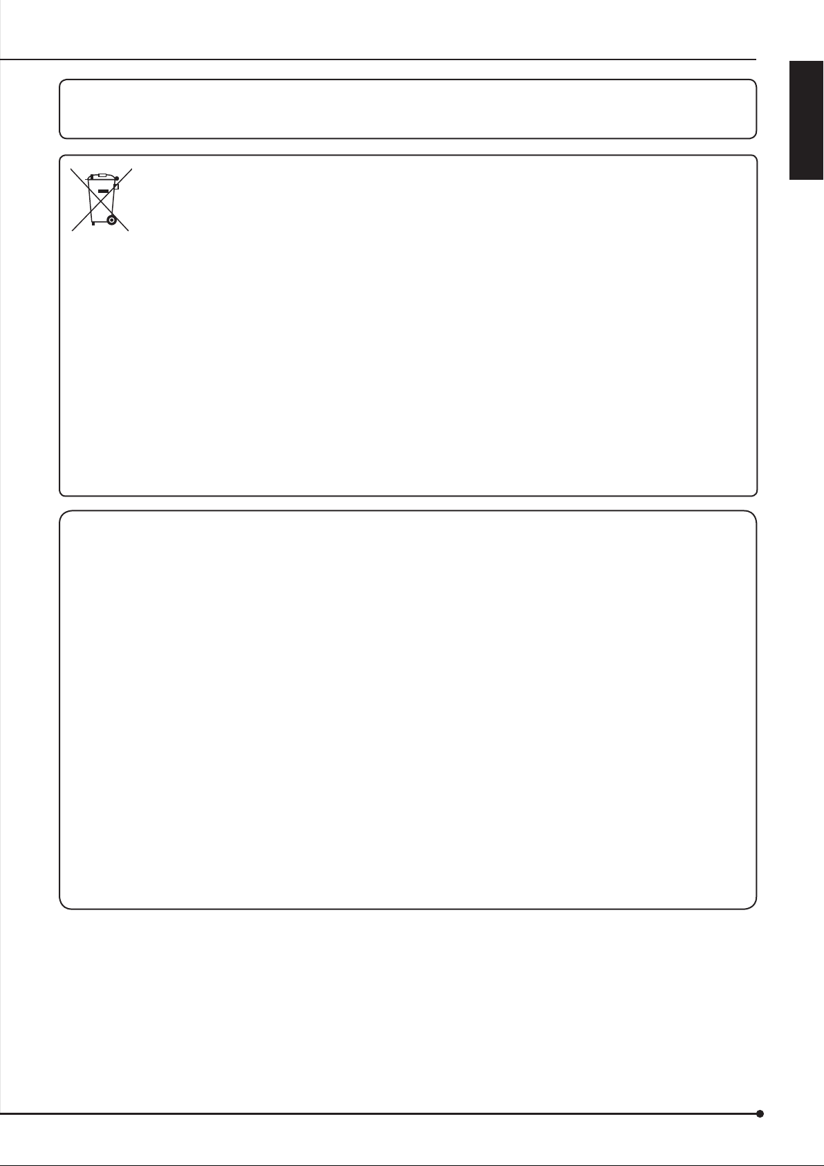
Note: This symbol mark is for EU countries only.
This symbol mark is according to the directive 2002/96/EC Article 10 Information for users and Annex IV, and/or
to the directive 2006/66/EC Article 20 Information for end-users and Annex II.
Your MITSUBISHI ELECTRIC product is designed and manufactured with high quality materials and components which can
be recycled and/or reused.
This symbol means that electrical and electronic equipment, batteries and accumulators, at their end-of-life, should be
disposed of separately from your household waste.
If a chemical symbol is printed beneath the symbol shown above, this chemical symbol means that the battery or accumulator
contains a heavy metal at a certain concentration. This will be indicated as follows:
Hg: mercury (0,0005%), Cd: cadmium (0,002%), Pb: lead (0,004%)
In the European Union there are separate collection systems for used electrical and electronic products, batteries and
accumulators.
Please, dispose of this equipment, batteries and accumulators correctly at your local community waste collection/recycling
centre.
Please, help us to conserve the environment we live in!
ENGLISH
About the hard disk drive (HDD)
•
This unit is equipped with HDD, which is a very delicate device. Therefore, handle this unit carefully.
•
Don't expose this unit to vibrations and shocks. It may be damaged when exposed to vibrations and shocks especially
during power-on or access to the HDD.
•
Don't unplug the power cord during recording/playback or power-on.
•
This unit is equipped with a system that automatically resumes and continues recording in the event of a minor failure in the
HDD or other components during recording. However, depending on the type of a failure in the HDD, this unit may not able
to continue recording. For early detection of failures, it is recommended to have this unit inspected every year.
•
In the event of a fault in the HDD, replace it immediately. For replacement of the HDD, please contact your Mitsubishi
dealer. (To replace the HDD, it is required to stop recording.)
•
Use recommended HDD only. For HDD supported by this unit, please contact your Mitsubishi dealer.
•
When the HDD is replaced, the recorded data are deleted. To ensure stable operation of this unit, the fi rmware may be
updated from time to time. The recorded data may be deleted in such a case.
•
When you dispose of or transfer this unit, handle the video data stored in HDD carefully and take all responsibilities related
to the disposal or transfer.
•
In the event of a failure in the HDD during normal recording or mirroring, this unit may not be able to resume recording after
rebooted, depending on the failure condition.
•
When you enable the mirroring function while the recorded data are stored in the HDD, the recorded data are deleted.
•
When you delete the data, the recorded images cannot be played back any more.
•
It is recommended to check regularly that the recorded data are played back correctly.
3

Caution and care (continued)
Installation location and handling
•
Before you fi rst use this unit, supply power to it for at least 48 hours to charge the built-in backup battery so that the built-in
power compensator circuit can be activated. When the battery isn't charged suffi ciently, the built-in clock may go wrong or
the unit may not able to recover in case of a power failure.
•
Don't plug this unit and high current devices (such as copier and air conditioning) into the same wall socket.
•
Place this unit on a level and stable surface. When it is used on an unstable surface, a failure may be caused.
•
Don't remove the outer covering of this unit.
•
Don't place this unit close to other devices. They may interfere with each other, disturbing video.
•
Don't place this unit on a heat source. In addition, don't place this unit near a heat source because this unit has ventilation
openings in its side. Otherwise the inside temperature may rise, causing a failure.
•
Don't place a strong magnetic object near this unit. It may affect the images adversely and cause loss of recorded data.
•
Don't expose this unit to volatile substances such as insecticide or don't leave this unit in contact with rubber or plastic
products for a long time. Otherwise the surface of the product may deteriorate or the coating may come off.
•
When this unit is placed directly on the waxed fl oor, the adhesion may increase between the fl oor and the non-slip rubber
pads on the bottom of the product, causing the fl oor coating to come off or be colored.
•
The HDD and cooling fans are motor-driven parts. To ensure stable recording, it is recommended to replace them every
30,000 hours of use as a guide assuming that the ambient operating temperature is 25°C. When replacing HDD, also
replace the vibration-proof rubbers at the screwed areas. (Note that this period is just for a guide of replacement interval
and isn't intended to guarantee the lifetime of the parts. They may be broken earlier because of shocks applied to the
product and ambient operating temperature.)
•
Be sure to use this unit within the allowable ambient temperature range (5° to 40°C) and humidity range (80% or less).
When you use the unit out of this temperature range, the internal parts may be adversely affected or a malfunction may
occur. In addition, when the temperature rises high, the characteristics of the HDD may deteriorate or its lifetime may be
shortened. When you use the unit in a low temperature environment, supply it with power for at least 10 minutes before
use.
•
Clean the product regularly to prevent the ventilation openings from being covered by dust.
Precautions for rack-mounting
•
When mounting this unit in a rack, ensure that the temperature inside the rack doesn't rise to 40°C or higher. When
installing a rack, you are recommended to install fans to keep the temperature inside the rack 30°C or lower.
•
Don't install a device that becomes hot under this unit. Otherwise the inside temperature may rise, causing a failure.
•
Don't give a shock to all HDD devices in the rack.
•
Before taking this unit in or out of the rack, be sure to turn off HDD devices being energized in the rack.
•
Don't place this unit near a device that generates vibrations.
Changing installation location
•
When moving this unit, be sure to turn off the MAIN switch, make sure that the unit is completely stopped, and then unplug
the power cord. When this unit is exposed to excessive shock while being energized, the internal electronic parts or HDD
may be damaged. Be careful especially while the power indicator or access indicator is blinking.
•
Don't move this unit for at least one minute after you turn off the power. Even after the power is turned off, the disc in the
HDD keeps rotating by inertia for a while and the head is in an unstable state. This unit in such state is more vulnerable to
vibrations and shocks than while being energized. Be careful not to give this unit even a slight shock for at least one minute
after turning off the power. Wait at least one minute for the disc to stop, and then you can move the product.
•
When moving this unit, cover it with shock absorbers to prevent shocks to the inside.
•
When placing this unit on a fl oor, lay it gently on a soft mat or cloth.
4

Maintenance
•
Gently wipe dirt off the cabinet with a soft cloth.
•
When dirt persists, clean it off using a cloth soaked in water-diluted neutral detergent and wrung well and then wipe dry.
•
When using a chemical cleaning cloth, follow its instructions.
•
Don't use solvent such as benzene and thinner. Otherwise the surface of the product may deteriorate or the coating may
come off.
Notes for constructing a surveillance system using this unit
•
When constructing a surveillance system using this unit, you are recommended to check its operation by connecting or
combining it with other devices in advance.
•
Don't use the alarm function of this unit for the purpose of making serious decisions or for applications involving human
lives.
•
When you unplug the power cord or turn off the breaker during recording, the HDD may be broken or recorded data may
become unable to be played back.
•
When the user or any third party uses external devices wrongly, or external devices are affected by electric noise or they
are damaged or repaired, the saved data may be lost. Mitsubishi doesn't take any responsibility for damages related to
such data loss.
•
Don't use the function to control the powers of external devices using the bus power of this unit.
•
External devices you want to use may not be suitable for the intended application of this unit. For details, you are
recommended to contact your Mitsubishi dealer.
•
Don't disconnect the cables while this unit is running. Otherwise a failure may be caused.
ENGLISH
For important recordings
•
Be sure to perform test recording before starting the practical operation of this unit, and also check regularly that the
recording is performed correctly according to the settings during the practical operation.
•
Mitsubishi doesn't compensate for data not recorded or not played back correctly because of a failure occurring in this unit
or connected devices during the use of this unit.
•
As a preparation for unexpected breakdown or accident, you are recommended to make regular backups of important
recordings. Though digital signals don't deteriorate, playback or recording may become impossible because of aging
deterioration of discs depending on the storage conditions.
Copyright
•
This unit records data digitally. Therefore, exercise caution in recording video images protected by copyright.
Supplied power cord
•
The supplied power cord is designed for this unit only. Don't use this cord for other products.
Network
•
It is recommended to confi rm with your network administrator about the network settings in advance.
•
As this unit is operated through network, you may suffer from damage as follows.
(1) Leakage or drain of information through this unit.
(2) Unauthorized operation of this unit by malicious third parties.
(3) Disturbance or deactivation of this unit by malicious third parties.
To prevent damage listed above, take suffi cient network security measures on your own responsibility.
5

Caution and care (continued)
Disclaimer
•
Mitsubishi assumes no responsibility or makes no compensation for operation error of your surveillance system, loss
of recorded data, or other damages or losses due to a failure in this unit. In no event will Mitsubishi repair, restore, or
reproduce recorded data.
•
In no event will Mitsubishi assume responsibility or liability for the following:
(1) Disassembly, repair, or alteration of this unit by the user or installer.
(2) Failure or breakdown in or damage to this unit resulting from misuse or careless handling by the user or installer.
(3) Inconvenience or damages resulting from inability to display or record images or to operate the unit's functions
correctly due to any reason or cause including breakdown or failure in this unit.
(4) Failure in this unit due to combination with other equipment manufactured by a third party, or inconvenience or
damages resulting from such failure.
(5) Inconvenience, damages, or claims arising out of breakdown in this unit or loss of recorded video data due to
replacement of the built-in HDD by the user or installer.
(6) Inconvenience or damages arising out of breakdown in this unit or inability to display or record images due to natural
disaster including earthquake and storm.
(7) Inconvenience, damages, or claims arising out of breakdown in the built-in HDD or loss of recorded video data due to
impact or vibration or environmental factors such as temperature at the installation site.
(8) Demand for damages or claim of infringement of privacy on the ground that the video monitored or recorded by the
user become public or are used for any purpose other than surveillance for whatever reason.
(9) Incidental, special, or consequential damages arising directly or indirectly related to this unit.
(10) Failure caused by any program created based on the command data provided by Mitsubishi, or inconvenience,
damages, or losses resulting from such failure.
•
This unit is intended for recording and playback of video monitored by cameras. Mitsubishi doesn't assure that this unit is
capable of preventing crimes.
Note
Open source software
Thank you for purchasing Mitsubishi network recorder DX-NV100E (hereinafter referred to as “Product”). Before using this
Product, please be sure to read the Software License Agreement on the next page with regard to the software contained in
“
this Product (hereinafter referred to as
terms and conditions of the Software License Agreement.
This Product contains software programs that are covered by GNU General Public License or GNU Lesser General Public
License. Such software programs are excluded from Licensed Software and not covered by the Software License Agreement.
For the terms and conditions for use of the software programs covered by GNU General Public License or GNU Lesser General
Public License, please see “Notice about software to which GNU GPL/LGPL is applied”*.
Other open source software contained in this product is excluded from Licensed Software and not covered by the Software
License Agreement. For the terms and conditions for use of these software programs, please see “Notice about other open
source software”*.
* The document of “Notice about software to which GNU GPL/LGPL is applied” and
software”
CD supplied with this Product.
are contained (in the format of electronic fi les as notice_GPL_LGPL.pdf) in the “OpenSoft_License” folder in the
Licensed Software”). By using this Product, you are agreeing to be bound by the
“Notice about other open source
6

Software License Agreement
This Software License Agreement (“Agreement”) is an agreement between you (“User”) and Mitsubishi Electric Corporation
(“Licensor”) with regard to the license to use Licensed Software.
Article 1 (Grant of license)
Licensor hereby grants to User a nonexclusive, nontransferable license to use Licensed Software.
Article 2 (License)
1. The license to use Licensed Software granted hereunder shall mean the User’s right to use Licensed Software solely on
this Product. User is hereby allowed to refer to the descriptions and instructions related to Licensed Software contained
in the user’s guide of this Product to the extent necessary for use of such Licensed Software.
2. User shall not reproduce, copy, or modify, in whole or in part, or make addition or alteration to Licensed Software and
pertinent documents.
3. User shall use Licensed Software in accordance with the operating instructions described in the user’s guide.
Article 3 (License conditions)
1. User shall not transfer to any third party the license stipulated in the preceding article.
2. User shall not disassemble, decompile, or otherwise analyze the source code of Licensed Software.
Article 4 (Ownership of Licensed Software)
All and any rights including copyrights related to Licensed Software and pertinent documents shall be owned by
Licensor or the original right holder who granted to Licensor the right to sublicense Licensed Software (hereinafter
referred to as “Original Right Holder”). User shall not own any rights other than the license granted hereunder with
regard to Licensed Software and pertinent documents.
Article 5 (Disclaimer)
Licensor and Original Right Holder shall make no warranties whatsoever with regard to Licensed Software and have
no liability for any damages suffered by User or any third party arising out of User’s execution of the license granted
hereunder, except in cases where any applicable laws are extended.
Article 6 (Responsibility toward third party)
Any issues related to intellectual property rights, including but not limited to rights of privacy, copyright, and patent,
involving any third party arising out of User’s use of Licensed Software shall be settled by User on its own responsibility,
and Licensor shall have no responsibilities for such issues.
Article 7 (Confi dentiality)
User shall keep secret the details of Licensed Software and pertinent documents provided hereunder and the contents
of this Agreement that are unknown publicly and shall not disclose or leak such details and contents to any third party
without consent of Licensor.
Article 8 (Termination)
In case of either of the following events, Licensor may terminate this Agreement immediately and may claim against
User for resulting damages it suffers.
(1) User’s violation of any provision of this Agreement.
(2) Occurrence of fi ling against User for seizure, provisional seizure, provisional injunction, or other forcible execution.
Article 9 (Disposal of Licensed Software)
If this Agreement is terminated pursuant to the preceding article, User shall dispose of Licensed Software, pertinent
documents, and any copies thereof in its possession within two weeks after termination hereof and shall provide
Licensor with a written certifi cation of such disposal.
Article 10 (Update of Licensed Software)
If User updates Licensed Software using an update CD supplied or sold by Licensor or any other means, this
Agreement shall remain applicable to the updated version of such Licensed Software, unless Licensor provides
additional separate terms and conditions for using the updated version of such Licensed Software.
Article 11 (Miscellaneous)
1. If any provision of this Agreement is determined to be invalid by law, the remaining provisions hereof shall remain valid
and enforceable.
2. If any doubt arises in relation to matters not defi ned herein or interpretation hereof, Licensor and User shall discuss
such doubt and attain a solution in a faithful manner.
ENGLISH
7

Features/Contents
Features
Network recorder having a large-capacity hard disc drive (HDD)
This recorder is able to record images captured by up to 16 surveillance IP cameras. In addition, this recorder is equipped with a
reliable, high speed large capacity hard disc drive.
HDD operation mode
You can select 2 types of HDD operation modes - spanning or mirroring.
Easy setup
You can easily make the settings of this recorder using the client software.
Alert function
This recorder is equipped with a terminal that informs troubles of the recorder.
Caution and care ...........................................................2
Note ................................................................................. 6
Open source software .................................................6
Software License Agreement ....................................... 7
Features .........................................................................8
Contents ......................................................................... 8
Major operations and their functions .......................... 9
Front view (door opened) ............................................9
Rear view ....................................................................10
Connections ................................................................. 12
Connection for alarm recording ...............................13
Cable clamping ..........................................................14
Caution in installing multiple recorders
in an EIA rack ..................................................14
Startup ........................................................................15
Specifi cations of this recorder ................................15
Contents
Setting the mode of this recorder .............................. 16
Troubleshooting ..........................................................18
Error indications ..........................................................20
Specifi cations ..............................................................22
Viewing displays
Tips
Reference information concerning operation
Notice
Cautionary items concerning operation
Reference item and page number
HDD operation mode .................................................16
Mode selection ...........................................................16
Illumination status of indicators ..............................18
Checking the status of the recorder
Troubleshooting .........................................................19
How to read this manual
(Refer to this information when operating):
(Caution required):
(See reference page):
<Self test function>
..18
8
Major operations and their functions
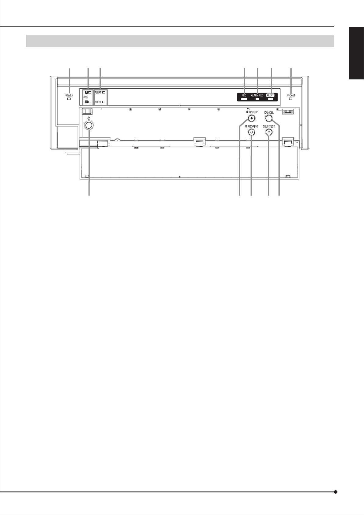
Front view (door opened)
3 4 5 6 7
1
2
ENGLISH
8
1 POWER indicator
When the POWER button is pressed while the MAIN
switch on the rear of this recorder is ON, this indicator
illuminates. When this recorder is in the standby status
or the MAIN switch on the rear of this recorder is OFF,
this indicator goes out. It takes about 1 to 2 minutes for
this recorder to be ready for operation after the POWER
button is pressed. When this recorder is in the process of
operation transition such as startup, this indicator blinks
and other operations are not acceptable.
2 HDD A, HDD B indicators (ACCESS indicators)
While HDD A or HDD B is being accessed, the
corresponding indicator momentarily blinks. They keep
blinking during recording of data.
3 ALERT indicators (for HDD A and HDD B)
In case of an error of HDD A or HDD B, they blink or
illuminate.
4 REC indicator
This indicator illuminates when this recorder starts
recording. It goes out when the recorder stops recording.
5 ALARM REC indicator
This indicator illuminates when this recorder starts alarm
recording. It goes out when the recorder stops alarm
recording.
6 ALERT indicator
This indicator illuminates when the recorder notifi es an
important event such as an error occurring inside. And it
blinks when the LAN LINK has an error.
109 11 12
7 IP-CAM indicator
This indicator illuminates when IP cameras are
connected. And it blinks when the connection of an IP
camera has an error. It goes out when IP cameras are
not connected.
8 POWER button
The power is turned on when this button is pressed
while the MAIN switch on the rear of the recorder is ON.
When this button is pressed again, this recorder enters
the standby mode. When this recorder is in the process
of operation transition such as startup, the POWER
indicator blinks and other operations are not acceptable.
9 REC/STOP button
When this button is pressed, this recorder starts
recording and the REC indicator illuminates. When this
button is held down for 2 seconds or longer, this recorder
stops recording and the REC indicator goes out. When
this button is held down for 2 seconds or longer during
alarm recording, this recorder stops recording.
10 MIRRORING button
This button illuminates when the recorder is in a mirroring
mode.
11 SELF TEST button
The self test starts when this button is pressed. It brinks
during the test and it illuminates if no error is detected.
And the indicator goes out when the error is detected.
12 CANCEL button
When this button is pressed while the alert is indicated,
the indication is cleared.
9
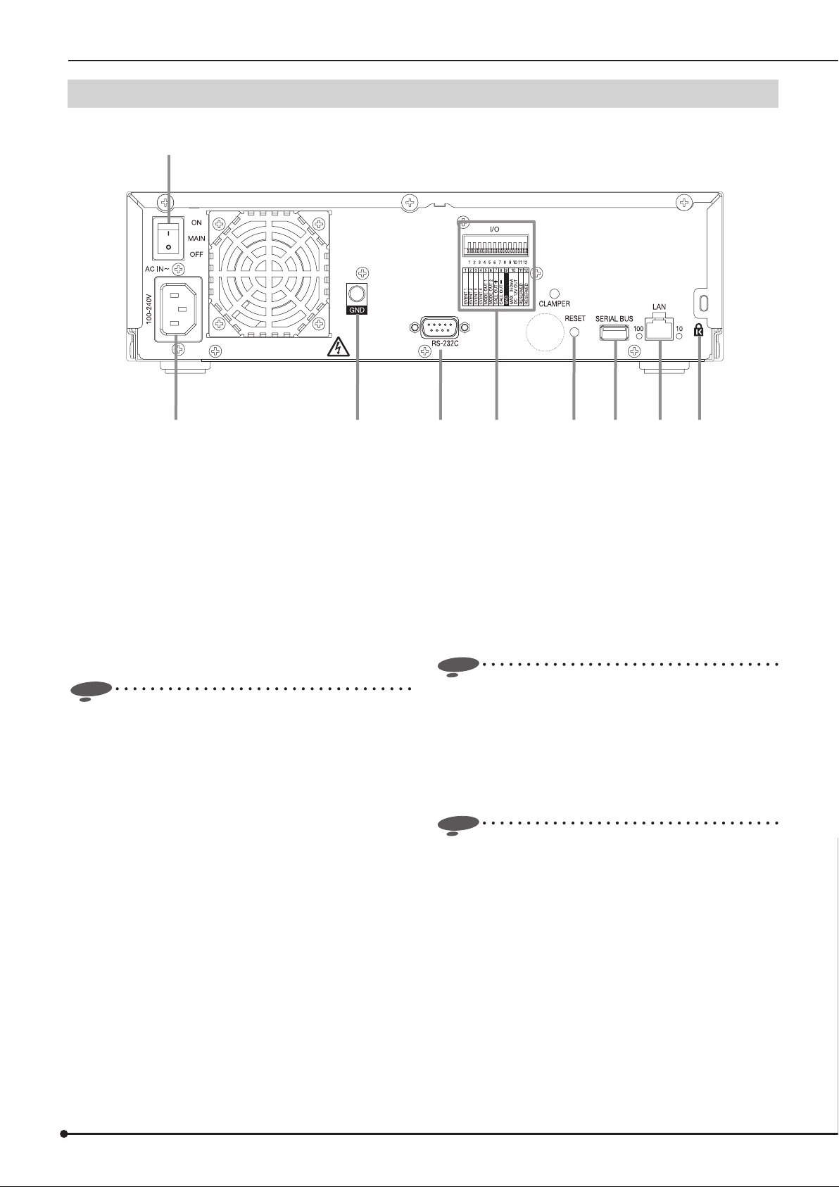
Major operations and their functions (continued)
Rear view
1
532 4 6 7 8 9
1 MAIN switch
This is the main power switch. To use this recorder, set
this switch to ON. Otherwise, the POWER button on
the front panel of the recorder cannot turn on or off the
recorder.
2 AC power socket
Use this socket to connect the supplied power cord.
Earth terminal is used for safety. Insert the power cord
of this recorder to the 100 to 240 V outlet with ground
terminal.
Notice
• When the power outlet does not have an earth terminal,
ask your dealer for grounding work (for pay). Never
connect the ground terminal of the power cord to the gas
pipe, water pipe, conductor rod and so on. Make sure to
use the supplied power cord.
3 GND terminals
This terminal is used as common ground terminal.
4 RS-232C connector
This connector is used only for service purpose.
5 I/O terminals
EVENT terminals (1 to 4)
When the EVENT terminal is grounded, alarm recording
starts.
MODE OUT terminals (1 to 2)
Output terminals to notify the current recorder status.
MODE OUT 1 terminal outputs the recording status.
MODE OUT 2 terminal outputs the alarm recording
status.
Notice
• The MODE OUT terminal may output a signal for several
seconds when the MAIN switch on the rear panel of the
recorder is turned on or the recorder recovers from a
power failure.
CALL OUT (+) terminal / CALL OUT (-) terminal
Output terminal to notify the trouble in the recorder and
its exclusive ground terminal (isolation terminal).
Notice
• The CALL OUT terminal may output the signal for
several seconds when the MAIN switch on the rear panel
of the recorder is turned on or the recorder recovers
from a power failure. Pay attention to this matter if you
use peripheral devices to issue notifi cation.
GND terminal
This terminal is used as common ground terminal.
DC 12V OUT terminal
This terminal outputs the direct voltage only when both
the MAIN switch and the POWER button are on. The
maximum electric current is 350 mA.
10

6 RESET button
When this button is pressed, this recorder is reset and
the power is turned off. In this case, image data, menu
settings, and the clock setting are retained.
7 SERIAL BUS ports
This connector is used only for service purpose.
8 LAN port
Port for the network between the IP cameras and the
client PC.
9 Keyhole for antitheft lock
This is a hole to connect a commercially available
antitheft cable manufactured by Kensington.
ENGLISH
11
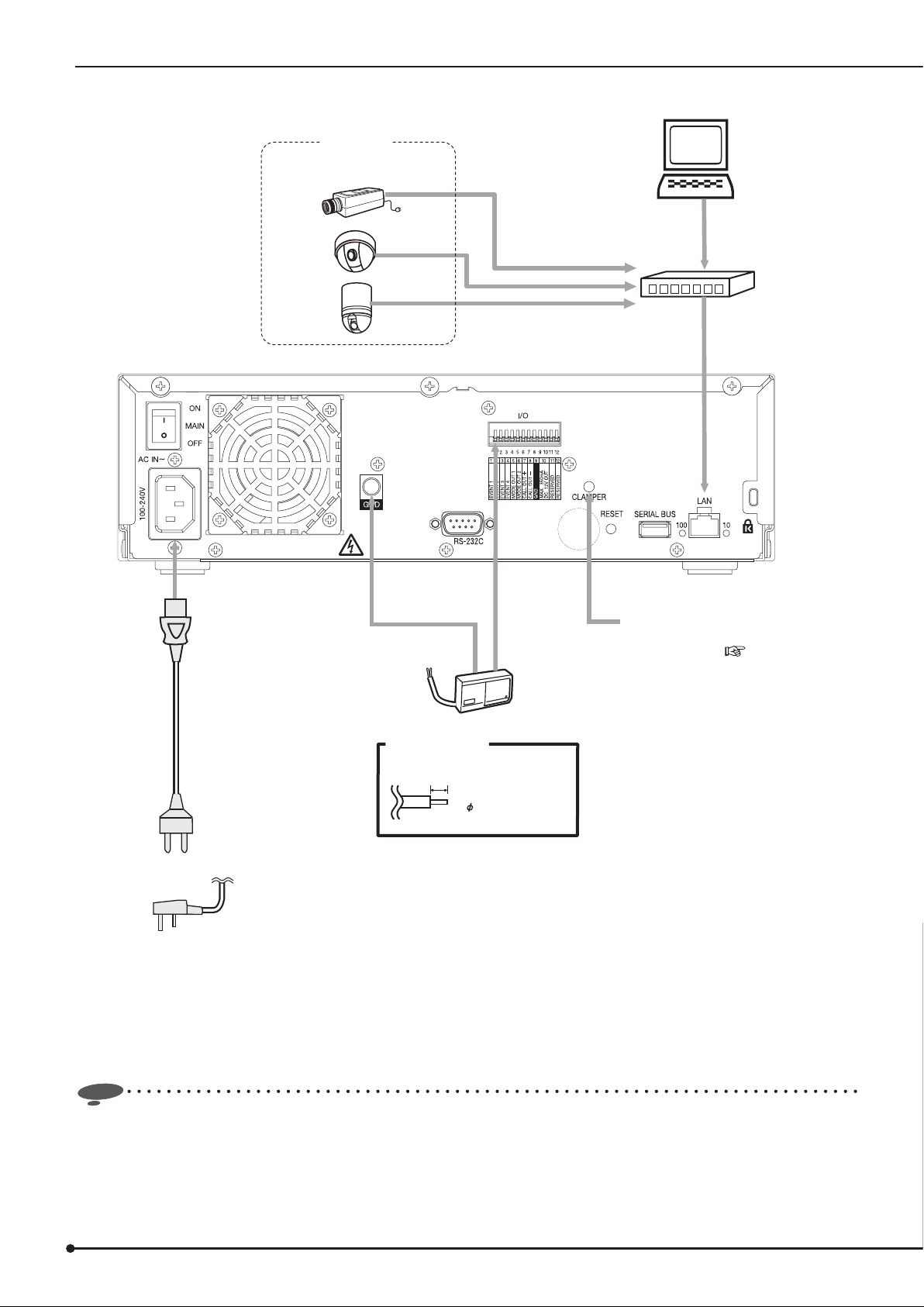
Connections
IP camera
See the supplied sheet for the
connectable IP cameras.
Client PC
Hub
Power cord
for the Continent
for U.K
ensor
S
<Cable termination>
Cable end connected to I/O terminal
5-7 mm strip-off
Applicable wire
0.32-0.65 mm
(AWG 28-22)
Secure the power cord using the
supplied clamp band to prevent
disconnection. ( Page 14)
Notice
• Depending on the operating condition of the recorder, its operation and control of external devices may become slow or
unstable.
12
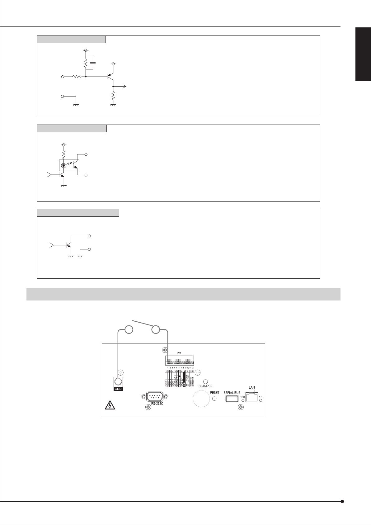
EVENT 1-4 input terminals
[Input circuit]
Input
terminal
10kΩ
22kΩ
5V
0.047µF
5V
[Input conditions] Grounding for 200 ms or longer
[Input interval] At least 1 second
[Specifications] Active: When terminals are short-circuited or
“Low” level voltage is applied.
Non active: Open
ENGLISH
GND
<Recorder's internal circuit>
CALL OUT output terminal
[Output circuit]
<Recorder's internal circuit>
MODE OUT 1-2 output terminals
[Output circuit]
<Recorder's internal circuit>
4.7kΩ
CALL OUT (+) terminal
CALL OUT (-) terminal
Output terminal
GND
[Specifications] Warning alarm signal (Photocoupler output)
Active: Short-circuit
Maximum current is 7 mA DC.
Non active: Open
Maximum voltage is 24 V DC.
* The terminal may output a signal for several seconds when the MAIN switch on
the rear panel of the recorder is turned on or the recorder recovers from a
power failure.
[Specifications] Active: “Low” level output
Maximum current is 7 mA DC.
Non active: Open
Maximum voltage is 24 V DC.
* Use the recorder within the ratings shown above.
* The terminal may output a signal for several seconds when the MAIN switch on
the rear panel of the recorder is turned on or the recorder recovers from a
power failure.
Connection for alarm recording
Following fi gure shows an example of the connection of alarm signal corresponding to alarm sensor 1.
Alarm switch
13
Connections (continued)
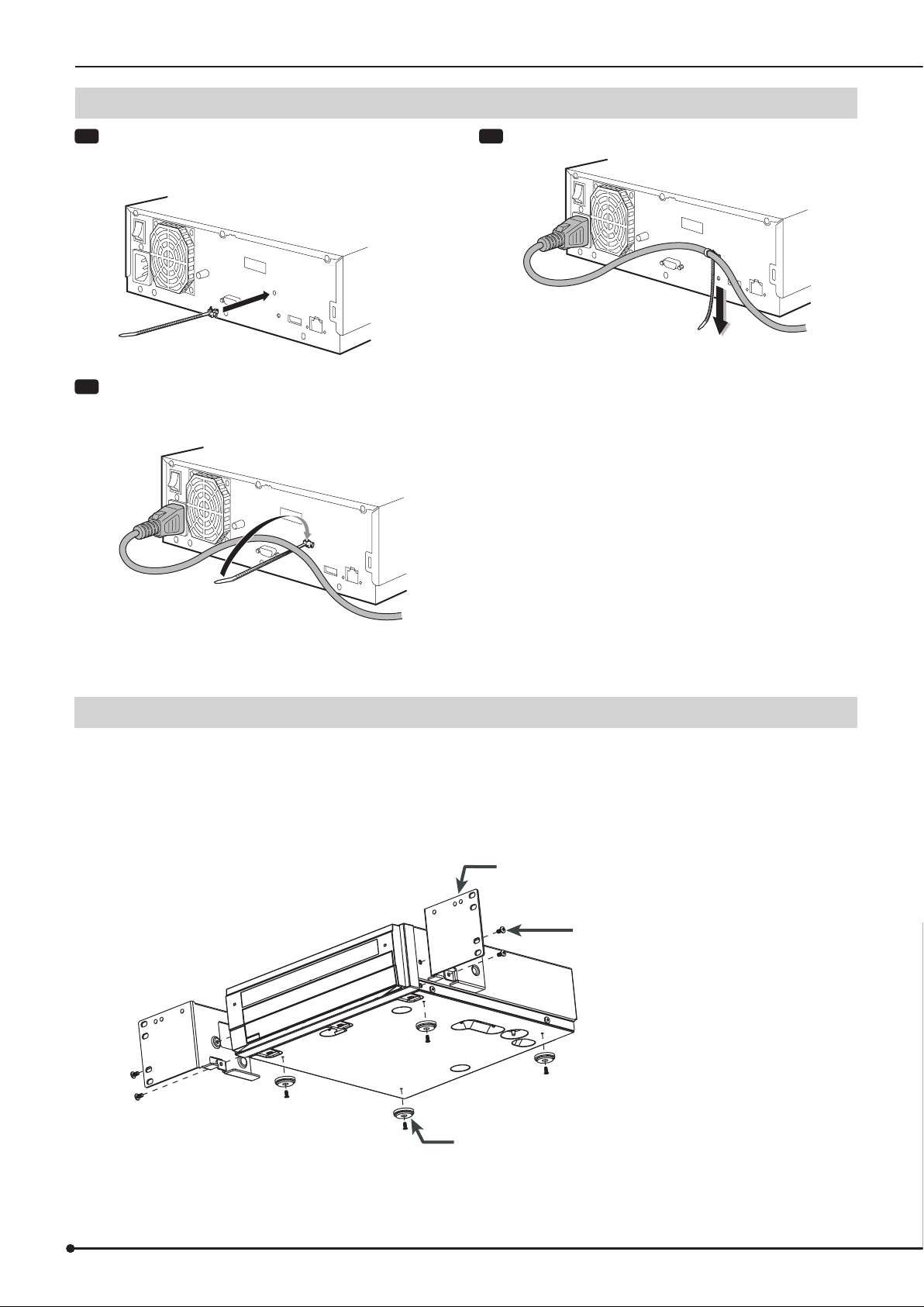
Cable clamping
Step
1 Insert the supplied clamp band into the clamp hole
on the rear of the recorder.
•
The clamp hole is for the power cable.
Step
2 Run the cable to be clamped around the clamp
band as shown in the fi gure.
•
The rough side of the band should face up.
Step
3 Pull the end of the clamp band until it is tightened.
Caution in installing multiple recorders in an EIA rack
Follow the steps below to install the recorder in an EIA rack (occupying 2U space) using the rack mount adaptor (DX-RM3).
1 Remove the feet from the bottom of the recorder. (4 feet)
2 Fit the rack mount adaptor using the screws on both sides of the recorder. (2 screws on each side)
3 Secure the recorder to the EIA rack using screws.
Prepare appropriate screws for your rack.
Rack mount adaptor (DX-RM3)
Screws on the recorder (2 screws on each side)
Feet on the bottom of the recorder (4 feet)
14
Startup
Step
1 Turn ON the MAIN switch on the rear panel of this recorder.
Step
2 Check that the POWER indicator goes out and then press the POWER button on the front panel of the recorder.
Step
3 Initial setting - IP address setting
Set the IP address of this recorder using the special application software stored in the supplied CD.
• The default setting of the IP address is 192.168.0.100.
• A full-rights user (user ID: "root" password: "admin000") has been registered as factory-preset users. You can change the
password, however, the user ID cannot be changed.
Step
4 Operation
• To operate this recorder, the special client software is required. Refer to the instruction manual supplied with the client
software.
• Users can access the recorder from multiple PCs using the same password and user ID. Up to 3 sessions can access
simultaneously.
Specifi cations of this recorder
Connectable IP camera IP camera See the supplied sheet.
Compression format MPEG4
Maximum number of connectable IP
cameras
Live image Live image display Available through the client software
Recording Compression format MPEG4 (Compressed by the connected cameras.)
Number of frames to be recorded Depends on the connected cameras and the specifi ed
Maximum number of frames to be
recorded (per channel)
Image resolution 720 x 576, 640 x 480, 320 x 240, 160 x 120
Recording rate Up to 7 Mbps
Alarm recording Yes
Pre-alarm recording Yes (15 seconds at the maximum)
16
Make sure to set the total recording value to 7 Mbps or less.
(Example) When connecting 16 cameras: 0.4 Mbps x 16
recording rate.
25 frames/s / 30 frames/s
(Depends on the connected cameras.)
(Depends on the connected cameras.)
ENGLISH
Tips
• Using the software stored in the supplied CD, you can make or check the settings of this recorder. For the usage, refer to
the instruction manual of the software.
1 NV100 IP-Address Setup (software for IP address setting)
2 NV100 Setting Tool (software for other settings)
3 NV100 System Tool (software for service)
15
Setting the mode of this recorder
HDD operation mode
This recorder has 2 HDD operation modes as described
below.
Notice
• When you change the HDD operation mode, initializing
the HDD is required. After changing the HDD operation
mode, you cannot startup this recorder unless the HDD
is initialized. Note that when you initialize the HDD, the
already recorded data cannot be played any longer.
Spanning mode (factory default)
This mode regards and uses 2 built-in HDDs as 1 HDD. The
total data capacity of 2 HDDs is available.
Notice
• When even one HDD fails, recording on the recorder
cannot be continued. You cannot play the data any
longer even when another HDD is normal.
Mirroring mode
This mode records the same data to 2 built-in HDDs
simultaneously.
If one of the HDDs fail, by replacing the failed HDD, the data
stored in the other HDD is automatically copied to the newly
mounted HDD and the HDDs are restored to the original
condition before failure. (Data synchronization)
Synchronization of 500-GB data takes about 8 hours. This
time is approximate and given as a guide only, assuming that
this recorder performs no other operations during the data
synchronization. Therefore, a longer time is required for the
data synchronization when the recorder is in the playback or
recording mode.
When the data synchronization is interrupted by the operation
such as power-off, the recorder resumes the synchronization
after the power is restored.
Notice
Mode selection
Before you change the operation mode of this recorder
(mirroring or spanning mode), make sure to delete the
HDD management information according to the following
procedures. When you change the operation mode without
deleting the management information, the data may not be
recorded properly.
In addition, when you change the operation mode, the already
recorded data cannot be played any longer. Before changing
the operation mode, check carefully that the settings are
made correctly and there will be no problem if the data should
become unable to be played back.
It is recommended to make backups of the important data
before changing the operation mode.
Notice
• Note that when you delete the management information,
the payback of the recorded data become disabled.
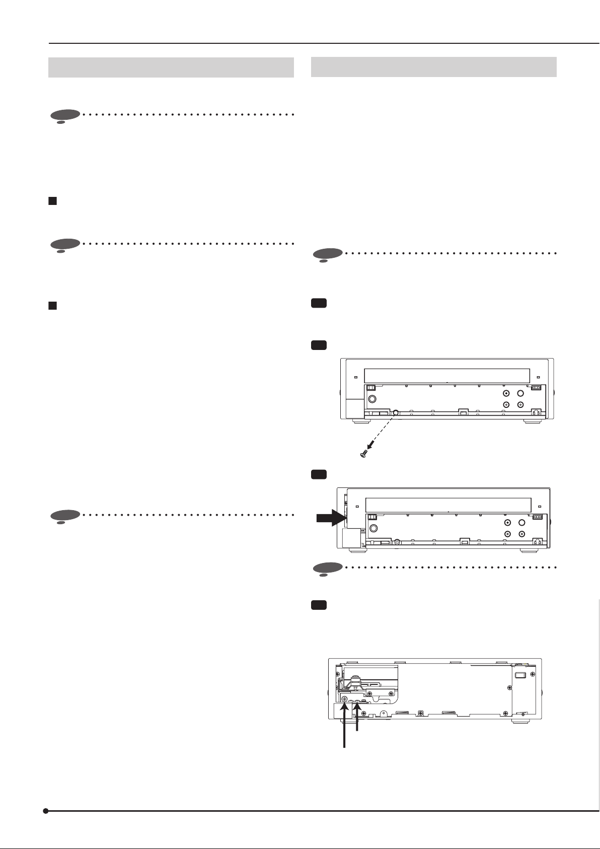
Step
1 Press the POWER button on the front panel and
then turn OFF the MAIN switch on the rear of this
recorder.
Step
2 Open the front door and remove the screw.
Step
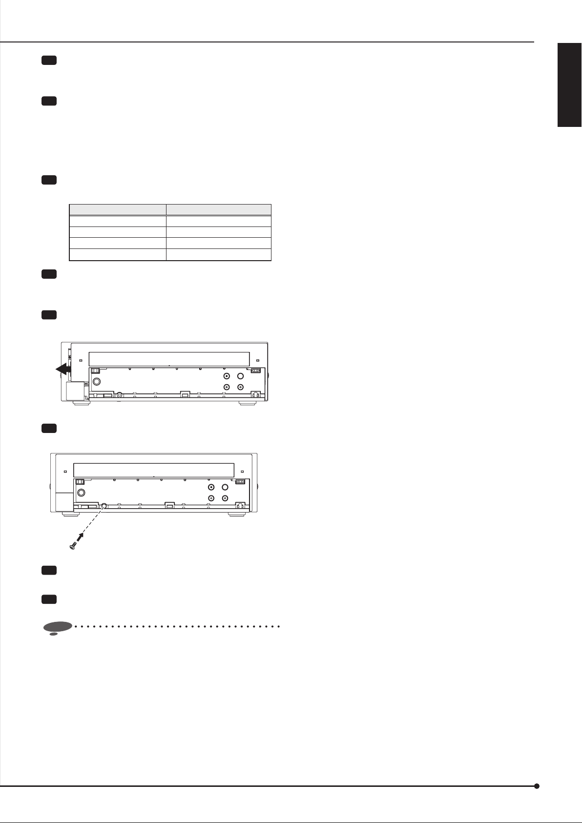
3 Slide the front unit to the right and remove.
• When you replace the failed HDD in mirroring mode,
make sure to use an unused HDD. When you mount the
used HDD, the data synchronization may fail and the
data may be damaged.
Notice
• Do not disconnect the cable connected to the front unit.
Step
4 Set the MODE rotary switch to 7.
• The mode is set using the MODE rotary switch inside
the front unit.
<Inside the front unit>
TEST button
MODE rotary switch
16
Step
5 Turn ON the MAIN switch on the rear panel and
then press the POWER button on the front panel of
this recorder.
Step
6 After the recorder boots up and the buzzer sounds,
press the TEST button.
• The management information deletion function is
activated and the HDD A or B indicator starts blinking.
Upon completion of the deletion, the indicator
illuminates.
Step
7 Set the MODE rotary switch to the number
corresponding to the desired operation mode.
MODE rotary switch HDD operation mode
0 Do not use
1 Spanning
2 Mirroring
3 to F Do not use.
Step
8 Press the POWER button on the front panel and
then turn OFF the MAIN switch on the rear of this
recorder.
Step
9 Attach the front unit.
• Attach the unit and push it to the left.
ENGLISH
Step
10
Fix the front unit with screw and close the front
door.
Step
11
Turn ON the MAIN switch on the rear of this
recorder.
Step
12
Initialize the HDD using the supplied software for
service.
Notice
• Note that when you initialize the HDD, the already
recorded data cannot be played any longer.
Before you initialize the HDD, check sufficiently that
there is no recorder having the same IP address in
the same network to prevent deleting the data in other
recorders unexpectedly.
17
Troubleshooting
Illumination status of indicators
The indicators on the front panel of the recorder blinks or illuminates, showing the condition of the recorder as shown in the table
below.
SELF
TEST
HDD operation
mode
Mirroring
Spanning
Error
POWER REC
Green Red Red Amber Green Green Green
ALARM
REC
ALERT IP-CAM
MIRRORING
Error after
startup
Camera
connection
Self test Executing
Error during
startup
: The indicator goes out.
: The indicator illuminates.
: The indicator blinks.
Normal (no error)
LAN LINK error
Error
No camera connected
Connection error
Camera connected
Error detected
No error detected
HDD recognition error
Error occurred or no response returned during
reading-out of the management information
Not formatted
Checking the status of the recorder
This recorder uses many electronic parts and HDDs and malfunction may occur in them. By checking the status of the recorder
(faulty or normal) using the self test function, you can fi nd a malfunction, if any, at an early stage and prevent the recorder from
remaining faulty.
Step
1 Press the SELF TEST button on the front panel of the recorder.
The indicator on the button blinks during self test. It illuminates when no error is detected.
When the indicator goes out, the error is detected. Consult your dealer.
<Self test function>
18
Troubleshooting
If problems with the unit persist even after you followed the suggestions below, please stop using the recorder, disconnect the
power cord and contact the retailer from whom you purchased the recorder.
Symptom Where to check Page
ENGLISH
The recorder does not turn
on.
Power is on, but the
recorder does not work.
Installation
Recording does not start. Are cameras to be recorded set correctly?
Recording does not stop.
Alarm recording does not
Recording
start.
Cannot access the recorder
from the personal computer.
Communication
Is the power cord properly plugged in?
Check that the MAIN switch on the rear panel is not OFF.
Check that the POWER indicator is not blinking.
The recorder does not work while the POWER indicator is blinking.
The protection functions may be working.
Reset the recorder by pressing the RESET button on the rear panel
using a pointed object such as a ballpoint pen and then turn on the
power again.
Is the ALERT indicator illuminating while the POWER indicator is
blinking?
Are both the SELF TEST and POWER indicators blinking?
If so, the HDD may not be identifi ed.
Check the illumination status of the IP-CAM indicator.
During normal recording or alarm recording, press and hold down
the REC/STOP button for 2 seconds or longer.
Are the alarm recording settings made correctly?
Are the external sensors and other devices connected correctly?
Is the personal computer connected to the recorder correctly?
Are the cables connected correctly?
Are proper cables being used?
Check that the IP address of the recorder and that of the personal
computer are different.
Is the recorder able to receive a ping command from the personal
computer?
Turn off the power of this recorder by the POWER button on the
front panel and the MAIN switch on the rear panel, and then turn it
on again.
Do not use broken hubs or routers or damaged network cables.
Otherwise, the system may not operate correctly.
Is the ALERT indicator blinking?
10, 12
10, 15
9
-
11
9, 18
-
9, 18
9
-
12, 13
12
12
-
-
-
9, 10
-
9
Data acquisition is
interrupted momentarily.
The buttons do not work.
Others
Is the heavy load imposed on the recorder?
The HDD may have a minor error.
Check that the POWER indicator is not blinking. The recorder does
not work while the POWER indicator is blinking.
-
-
9
19

Error indications
When an error occurs in the recorder, the log is registered in the log list. To clear the alert, press the CANCEL button.
*1 : Alert level
Minor : Check the cause of the alert. By clearing the alert, you
can keep using the recorder. If the same alert appears
frequently, contact your dealer.
Major : Contact your dealer.
*2 : (The following numbers are displayed in
.)
01 : CH 1 02 : CH 2 03 : CH 3 04 : CH 4
05 : CH 5 06 : CH 6 07 : CH 7 08 : CH 8
09 : CH 9 10 : CH 10 11 : CH 11 12 : CH 12
13 : CH 13 14 : CH 14 15 : CH 15 16 : CH 16
<Error log>
LOG display
LOG number
5100 LOG5100 • The recorder is rebooted. • Press the CANCEL button on the
5101
5121
9900 LOG9900 • The HDD management information is
6100 LOG6100 • No HDDs can be recognized. • Check whether the HDD has no
6200 LOG6200 • No internal HDDs can be recognized. • Contact your dealer. Output Major
example in the
client software
LOG5101
LOG5121
Cause Remedy
• The recorder is rebooted for watchdog
operation.
damaged.
front panel to clear the alert.
- Output Minor
- Output Minor
malfunction.
• Turn off the power of the recorder
and then turn it back on.
• Check the connection.
Call-out
signal
output
Output Minor
Output Minor
Alert
level*1
6400 LOG6400 • The HDD cannot be recognized during
mirroring mode.
1400 LOG1400 • An error occurs during recording. • Check whether the HDD has no
2400 LOG2400 • An error occurs during data acquisition. • Start the operation again.
1500
1600
1300
2300
54
*2 LOG54 *2
LOG1500
LOG1600
LOG1300
LOG2300
• An error is detected in the data stored in
the HDD.
• An error occurs during writing/reading
the HDD.
• The HDD is exposed to vibrations and
shocks.
• The IP camera is not connected correctly. • Press the CANCEL button on the
• Check whether the HDD has no
malfunction.
• Turn off the power of the recorder
and then turn it back on.
• Check the connection.
malfunction.
• Turn off the power of the recorder
and then turn it back on using the
POWER button on the front panel.
• Turn off the power of the recorder
and then turn it back on using the
MAIN switch on the rear panel.
• Press the CANCEL button on the
front panel to clear the alert.
• Check the HDD. Does not
• When no abnormality is found, you
can keep using the recorder.
• When errors occur repeatedly, check
the HDD and cables and reboot the
recorder.
front panel to clear the alert.
• Check whether the recorder and
camera are connected correctly and
turned on.
Output Minor
Output Minor
Does not
output
output
Does not
output
Output Minor
Minor
Minor
Minor
20
<Error log> (continued)
LOG display
LOG number
5200 LOG5200 • The recorder is used in a high
example in the
client software
Cause Remedy
temperature environment.
• Turn off the power and install the
recorder in an environment of 5 to 40
°C.
Call-out
signal
output
Output Minor
Alert
level*1
ENGLISH
5201 LOG5201 • The recorder is used in a high
temperature environment.
5300 LOG5300 • The fan stops. • If the fan stops, turn off the power
8000 LOG8000 • An error occurs in LAN LINK. • Check the LAN connection. Does not
8501 LOG8501 • Recording stops temporarily because the
received data size becomes too large.
• Contact your dealer. Output Major
Output Major
and contact your dealer immediately.
output
- Does not
output
<Operation log>
LOG display
LOG number
0001 P-LOSS Power failure occurs during operation.
0002 P-RETURN Power failure is recovered.
0110 REC OFF Normal recording stops.
0111 REC ON Normal recording starts.
0112 REC COM OFF Normal recording stops via communucation.
0113 REC COM ON Normal recording starts via communucation.
example in the
client software
Operation
Minor
Minor
0501 SYS RST RESET button on the rear panel is pressed.
0590 WNG RESET The call-out output is stopped.
0900 FW VER.UP Main fi rmware is updated.
21

Specifi cations
Rated Power Supply 100 to 240 V AC, 50/60 Hz
Rated Input 0.58 - 0.32 A (100-240 V)
Operating Temperature 41 °F-104 °F (5 °C to 40 °C)
Relative Humidity Max. 80 (%)
Altitude Max. 2000 (m)
Dimensions 300 (Width) x 350 (Depth) x 88 (Height) (mm)
Weight 6.7 kg (with 2 HDD mounted)
Control terminals
EVENT (1-4) Active: When terminals are short-circuited or “Low” level voltage is applied.
Non active: Open
Mode out (1-2) Active: “Low” level output
Maximum current 7 mA DC
Non active: Open
Maximum voltage 24 V DC
Call out +/– Active: Short-circuit
(Photo coupler output) Maximum current 7 mA DC
Non active: Open
Maximum voltage 24 V DC
Ground terminal
DC 12 V Output Maximum 350 mA DC (when Main switch and power button are turned on)
Serial port RS-232C D-SUB 9 pin
LAN Connector form: RJ-45 Physical interface: 10BASE-T/100BASE-TX
Serial bus
Accessories: AC power cord (For U.K/for the Continent) 2
Cable clamping band 2
Installation and operation manual (this manual) 1
CD 1
Sheet for supplementary information 1
(IP cameras connectable to DX-NV100E)
Design and specifi cations are subject to change without notice.
22

 Loading...