

Page 1
MITSUBISHI
INDUSTRIAL
SEWING
MACHINE
Model
Thank
you
you
for
your
will
read
through
A
MITSUBISHI
purchaseof"Mitsubishi"
this
manual
book
for
ELECTRIC
machineatthis
your
long
periods
time.
using
CORPORATION
We
efficiently.
hope
Page 2
(
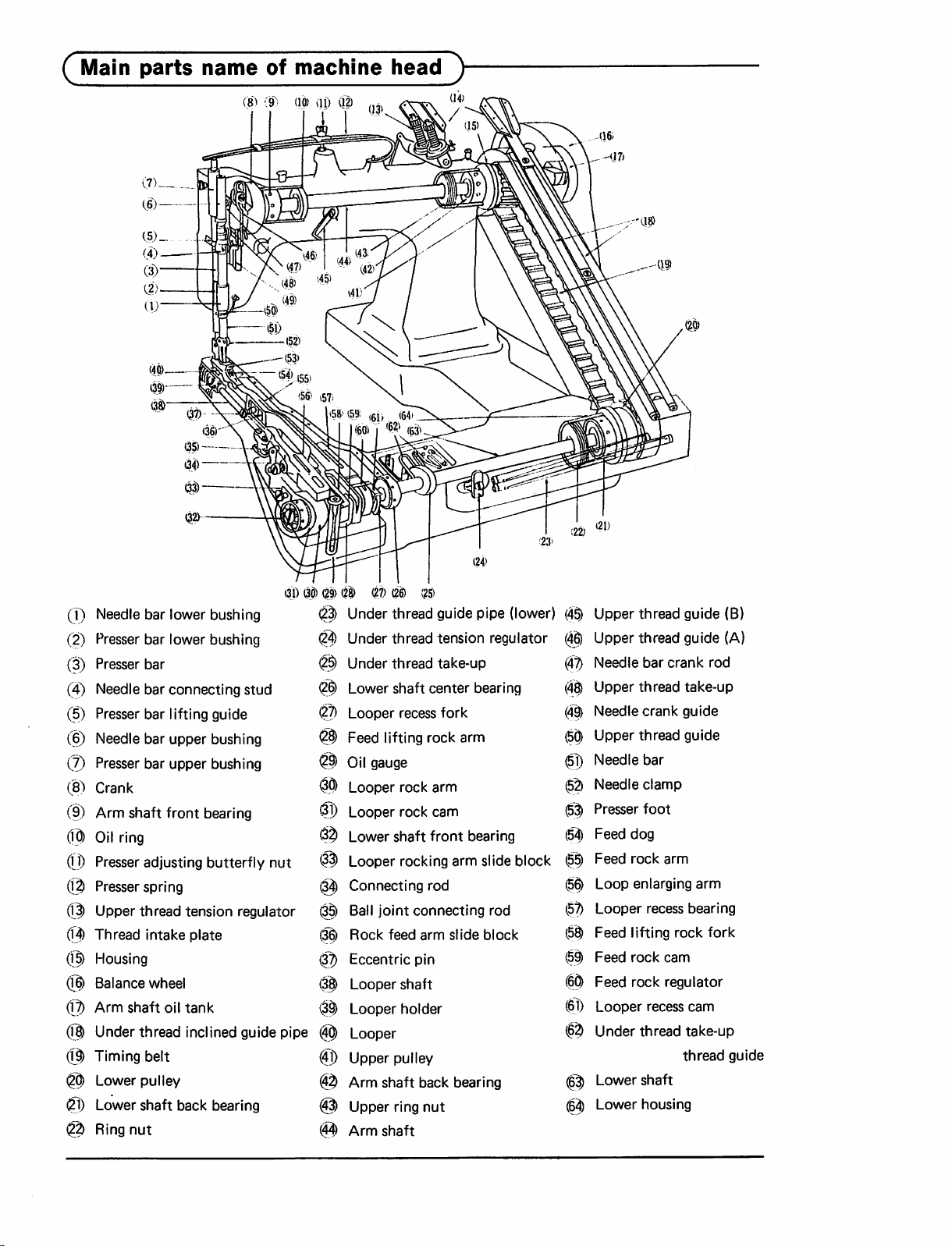
Main
parts
nameofmachine
(8)
(9":
(10)
(If) (1^
head
y
Nee(Jle
0
Presser
(2)
Presser
(3)
Needle
(4)
Presser
0
Needle
Presser
@
Crank
(8)
Arm
(9)
Oil
0
Presser
©
Presser
Upper
®
0
Thread intakeplate (||)
bar lower
bar
lower
bushing
bushing
bar @
bar
bar
bar
bar
shaft
connecting
lifting
upper
upper
front
stud
guide
bushing
bushing
bearing
ring
adjusting
spring
thread
butterfly
tension
nut
regulator
Housing
Balance
wheel
Armshaft oil tank
Under
thread
@
@)
Timing
Lower
inclined
belt (g)
pulley
guide
Lowershaft back bearing @
Ring
nut 0
(31)
pipe
# (|
0)
(27)
(26)
(25)
Under thread guide pipe (lower) (4^
(i|)
Under
thread
0
Under thread take-up
Lowershaft center bearing
®
Looper
®
Feed lifting rock arm l5^
®
Oil
@
®
*|J)
®
®
(0
@
(3^
(3^
gauge
Looperrockarm
Looper
Lower
Looper
Connecting rod (|^
Ball
joint connecting rod 0
Rock feed arm slide block (5$
Eccentric
Looper
Looper
tension
recess
fork
rock
cam
shaft front
rocking
bearing
arm slideblock 0
pin 0
shaft 0
holder
Looper
Upper
pulley
Arm shaft back bearing
Upper ring nut
Arm
shaft
regulator
Upper
thread
Upper thread guide (A)
@
(aT)
(4i^
(4^
(0
(0
(5|)
0
0
0
(0
(0
Needle
Upper
Needle
Upper
Needle
Needle
Presser
Feed
Feed
Loop
Looper
Feed
Feed
Feed
Looper
Under
Lower
Lower
bar
crank
thread
crank
thread
bar
clamp
foot
dog
rock
arm
enlarging
recess
lifting
rock
cam
rock
regulator
recess
thread
shaft
housing
guide
take-up
guide
guide
arm
bearing
rock
cam
take-up
thread
(B)
rod
fork
guide
Page 3
(
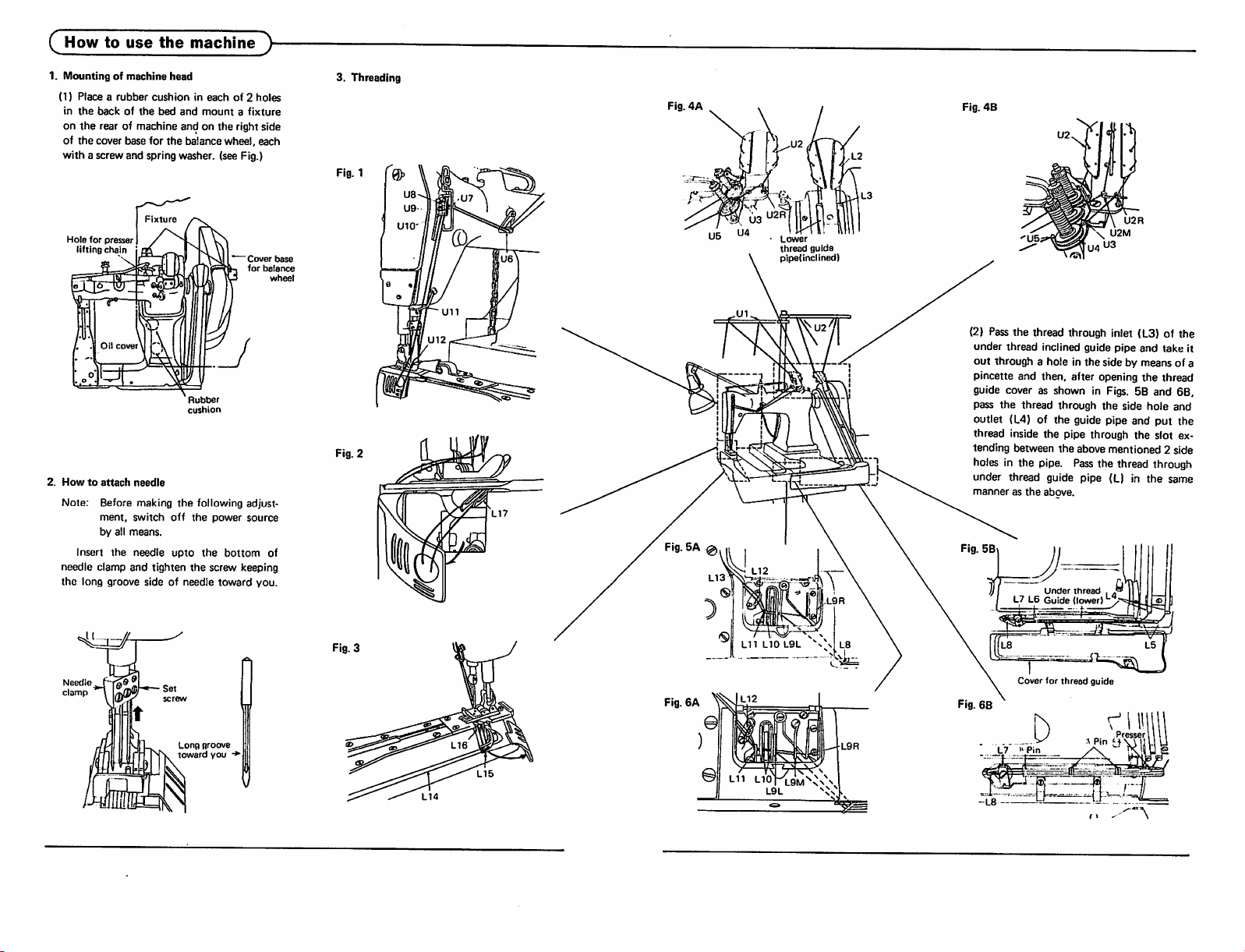
Howtouse
1.
Mountingofmachine
(1)
Placearubber
in
the
backofthe
on
the
rear of machine and on the right side
of
the
cover base for
the
machine
head
cushionineachof2
bed
and
mountafixture
the
balance wheel, each
with a screw and spring washer, (see Fig.)
}-
holes
3.
Threading
Fig. 1
Fig.
4A
Fig. 4B
Hole
for
presser
lifting
chain
Oil
cover
2.
Howtoattach
needle
Note: Before making
ment.
switch
by all
means.
insert
the
needle
needle clamp and tighten
the
long
groove
sideofneedle
Fixture
Rubber
cushion
the
following adjust
off
the
upto
the
the
screw keeping
power
bottom
toward
Cover
for
balance
source
you.
of
whee
base
Fig. 2
Fig. 3
Lower
thread
guide
plpe(inclmed)
\ U2M
(2) Passthe thread through inlet (L3) of the
under thread inclined guide pipe and take it
out
through a hole in the side by means of a
pincette and then, after opening the thread
guide cover as shown in Figs. 5B and 6B,
pass
the
thread
through
the
side
hole
outlet (L4) of the guide pipe and put the
thread inside the pipe through the slot ex
tending between the above mentioned 2 side
holes in the pipe.
Pass
the thread through
under thread guide pipe (L) in the same
mannerasthe
Fig. 5B
L7 L6
above.
Under
Guide
thread
, .
(lower) ^
and
Need
clamp
e
Set
screw
Long
toward
groove
you
Fig.6A
Cover
for
thread
guide
^
LIT
L10
Fig.
6B
h
\J
L7
"Pin
_
^'
PresserUll
"11
Page 4

(^Howtouse
4.
Adjustmentofthread
O
Well
In
caseofupper
too
is
too
6.
Upper
thread
tension
**
Upper
threadisadjusted
lower
thread
tension.
**
Upper
thread
sion
regulating
Strengthen
Weaken
the
machine
tension
balanced
weakorlower
strong
stitch
thread
is
thread
accordingtothe
tensionisadjustedbyten
thumb
Thumb
nut.
nut
^
5.
Thread
1.
Lower
regularly
of
required
ease.
The
be
2.
Upper
en
3. Irregular
in its
Checkupthe
7.
Lower
Weaken
tension
thread:
through
in case of
When
threadispulled,
to
be
pulled
thread
weak.
gradually
thread:
tension
Start
watching
stitching;
mounting
side.
wrong
thread
'W
Under
tension
thread
tension
Strengthen
Adjusting
startingtosew
threadingismade
looper
eye
the
lower
out
smoothly
is
recommendable
weakly
the
and
trial
Check up
threading.
device
•
screw
and
thread
strength
stitches.
the
|i(
-
the
needle
end
is
in
to
8.
Adjustmentofstitch
(1)
For
adjusting
the
large screw on the oil cover,
length
stitch
length, first remove
bring screw 0 (white) on the feed cam into
the
sight
through
balance
Loosen
wheel
under
(2)
increases
wheel.
the screw 0 and then turn the
further
the
hole,
Counter-clockwise
the
the
hole by
until screw
(see Fig.)
rotationofscrew
lengthofstitch
(B)
and
turning
(red)
vice versa.
After the adjustment, tighten screw 0 .
(see Fig.)
9.
Adjustmentofpressureonpresser
Pressure on
justedinaccordance
sewn.
the
presser
with
Butterfly nut Thumb
foot
footisto
materials
nut^
and
the
comes
(B)
be ad
to be
10.
o
Cutting
At
thread
the
material
to
that
Feed
cam
( I
Large
screw
of
thread
the
tipofthe
cutterisprovided,
downward
point,
the
thread
(A.
bedofthe
and
when
canbecut.
(White)
machine
by
it is
(Red)
pulling
sewn
a
up
Presser
spring
Page 5

Adjustment
1.
Mounting
guide
positionofthe
(top of
arm)
y
upper
0
(Make proper loop with needle thread.)
When
the
position,
heightofthe
upper
2.
Mounting
thread
set
thread
angleofthe
take-up lever is at its lowest
the
threadtobe looped by
diameterofthe
wire
guide (arm) (D is
upper
thread
guide (g)
(Adjust
When
position,
thread
and
level.
3.
Mounting
take-up
When
lower
of 4 —5 mm
contact
Thread
operation
Thread
slow
tensionofthe
the
thread
it is
recommendable
between
the
upper
positionofthe
lever
the
looperisat
thread
take-up
from
with
the
take-upisimprovedincaseofquick
take-up
the
upper
thread
the
lower
thread
take-up.)
lever is at its lowest
thread
guide
become
lower
its
extreme
lever is
setatthe
mounting
thread.
(high).
take-upisnot
operation
(low).
improvedincase
thread
which
made
of.
to
make
guide (arm)
almost
thread
left,
plate
making
the
the
the
the
place
of
Upper
Needle
at
lowest
position
/Upper
thread
take-up
\i')
' y '
bar
thread
V"
Upper
horizontally.
i
guide
^
,7
threadispositioned
\
Upper
extreme
position
""'pp''
Thread
thread
Lower
thread
take-up
Looperatits
\
right
guide
4—5
""'P®
@
mm
4.
Relationofneedle
(1) When
tion,
position
center
shouldbe3.5
be
looper
(2)
adjusted
the
of needle
adjusted
tightening
The
height of
the
looper will be at its extreme right
where
that
and
needle bar is at its lowest posi
the
and
mm
(9/64").
by
resetting
screw.
the
when
from its lowest position,
meets
with
the
eyeinthe
its
advance
5.
Positionofneedle
The
guard
it
canbeadjusted
which
tubular
motion,atthe
guard
clearance
shouldbeapproximately
can
part.
be
between
after
reached
looper
distance
the
needle
the
between
tip of
The
distance
the
looperatthe
bar
should
needle is going up
the
looper
same
level.
the
0.1
loosening
from
the
the
the
looper
can
be so
needle eye
which is in
needle
mm
the
bottom
and
and
screw
1
0
3.5
mm
Looper
eye
and
Needle
eye
Forward
Needle
Needle
guide
of
Backward
\
r
Approx.
0.1
mm
Page 6

(^Precaution
Turn
the
screwonthe
fill
the
tank
When
the
line,
lubrication
Give
close
whenever
before
balance
top,
with
oil level
checkingsofthe
it is low. (see Fig. 1)
wheeltobring
remove
oiltofull.
drops
will
stop.'
the
below
startingtooperat^
plug
oil
Oil cut (g) at 3 places are to be oiled 5 cc
each
for
the
initial
and
thereafter
drops at least twice a week, (see Fig. 2)
Remove
fill
the
give
the
The
oilintank
twiceaweek
the
gauge.
the
oil gauge in Fig. 3 and
tank
with
150ccof
level uptothe
should
and
kept
mark on
be
checked
uptothe
and
oil,
the
screw,
the
center
replenish
5
which
the
gauge.
at
mark
Oil
gauge
plug
and
or
will
least
on
Fig. 1
Plug
screwv
Center
line
6
Fig. 2
(D)
Sump
Arm
shat
tank
(c
Oil
cup
/ \
I
(A)
Oil
gauge
(K
Plug
4.
Maintenance
1. As
accumulationofdustonthe
feed
affect a proper feed of the material, it should
be periodically brushed off.
2. Often
the
dust
the
looper function is impaired by
collected
on
it,
anditshould
cleaned periodically by removing its cover.
Also
at
the
same
time
clean
the
pathess.
6.
Mounting
oval
press down as far as it touches
plateasshown
of stitching on
Fit
the
slotinthe
and
adjustmentoftapper
guide plate of the lapper into the
middleofthe
oil
cover
the
in Fig. 4. Where
the
material to be lapped is
the
not properly located, adjust it after loosen
ing screw A , and when the width of lap is
not proper, adjust it by tightening screw B .
dog
be
thread
and
throat
point
5.
Drainingofwaste
1.
Excessive
sump (p) and in
at
the
jaw of the arm, and it should be peri
odically removed by means of a
oil in
oil
the
the
armiscollected
lower
partofthe
spuit
piece of waste cloth, (see Fig. 2)
2.
Waste
oil in
the
bedisdrained
the hole under the bed by removing plug
(Fig. 2)
Accumulation
lower
thread
of
take-up
oil in
and,
the
bed
therefore,
wets
thread. A special care should be taken in
periodical draining of
Fig. 4
the
waste oil.
©
in
plate
or a
through
(0.
the
the
Page 7

(^Specifications}-
Model
DV-440+suffix
Material
No.ofneedles
Max.
Max.
Needle-bar
Presser-foot
Presser-foot
MIn.
Needle
weight
speed
stitch
cylinder
type
(spm)
length
stroke
type
clearance
circumference
Weight (net/gross)
Shipping
Needle
measurement
type
(Organ
mm
In
Organ
Singer
Schmetz
mm
in
(head only)
needles
are
1-1/16
standard)
-21
Light
2
27
27:45
3.2,4.8,
1/8,
-20
Medium
2 3
4000
TVxl
m -
149x1#7-
Nm
6.4
3/16,1/4
30.2
1-3/16
70-110
-30
18
18
3.2+3.2
1/8+1/8
-22
Medium&heavy
2
4.2mm
Regular
10mm
178mm
TVx5
149x5
44:31
6.4
1/4
(Sspl)
33
1-5/16
(3/8")
jCI1 -
1/11-22
Nm
80-110
3.2+3.2
54/67kg
0.21m^
1/8
-32
(7")
-23
3
3500
22
1/8
2
TVx5
149x5
44:31
-23-U
Denim
2
36
1-27/64
Union
#14-23
#14-23
Nm
6.4
1/4
-33
3
Regular
90-160
3.2+3.2
1/8+1/8
A
MITSUBISHI
HEAD
OFFICE
MITSUBISHI
DENKI
ELECTRIC
BLDG.MARUNOUCHI.
TOKYO
CORPORATION
100.
TELEX
J24532
CABLE
MELCO
TOKYO
W'l'00532X0l
 Loading...