

Page 1
A
MITSUBISHI
INDUSTRIAL
SEWING
MACHINE
Model
classes
Compound
Compound
Feed
Feed
Single-Needle
Double-Needle
Lockstitch
Lockstitch
INSTRUCTION
FOR
OPERATION
MANUAL
Page 2
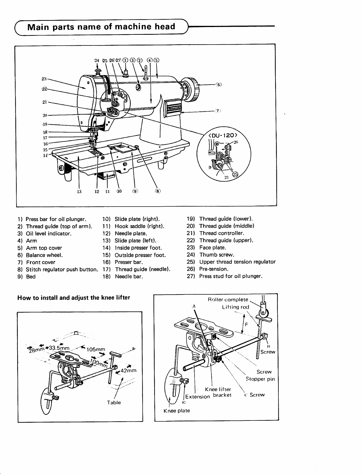
Main
parts
nameofmachine
24
(25
<26167)CD(3) (2)
-m
C^)
head
®
^
1)
Press
bar
for
2)
3)
4)
5)
6)
7)
8)
9)
Thread
Oil
Arm
Arm
Balance
Front
Stitch
Bed
level
top
cover
regulator
guide
indicator.
cover
wheel.
Howtoinstall
*2^^^
oil
plunger.
(topofarm).
push
button.
and
adjust
the
105mm
10)
11)
12)
13)
14)
15)
16)
17)
18)
knee
Table
Slide
Hook
Needle
Slide
1
nside
Outside
Presser
Thread
Needle
lifter
42mm
plate
saddle
plate.
plate
presser
presser
bar.
guide
bar.
(right).
(right).
(left).
foot.
foot.
(needle).
Knee
Thread
19)
20)
Thread
21)
Thread
22)
Thread
23)
Face
plate.
24)
Thumb
25)
Upper
Pre-tension.
26)
27)
Press
stud
Roller
Knee
'Extension bracket
plate
guide (lower).
guide (middle)
controller.
guide
(upper).
screw.
thread
tension
for
oil
plunger.
complete
Lifting
lifter
rod
\
c:
regulator
Screw
Stopper
Screw
Screw
pin
Page 3
How
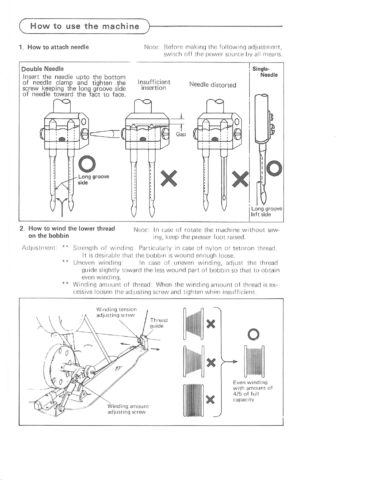
1.
How
to
to
attach
use
needle
the
machine
Note:
Before
switch
making
off
the
the
power
following
source
adjustment,
by all
means.
Double
Insert
of
Needle
the
needle
needle
clamp
upto
the
bottom
and tighten the
screw keeping the long groove side
of
needle
How
on
the
to
toward
wind
bobbin
the
the
lower
fact
to
thread
face.
Insufficient
insertion
Note:
In
ing,
case
keep
Needle
of
rotate
the
presser
distorted
the
machine
foot
raised.
without
sew
Adjustment:
**
**
Strength
It is
Uneven
guide
even
of
winding;
desirable
winding:
slightly
winding.
Particularlyincaseofnylonortetoron
that
the
bobbiniswound
In
case
of
toward
the
less
wound
** Winding am{;unt of thread: When
cessive
loosen
Winding
the
tension
adjusting
screw
.
adjusting screw /
Thread
guide
—
Winding
adjusting
amount
screw
uneven
enough
winding,
loose.
adjust
partofbobbinsothattoobtain
the
and
winding
tighten
amountofthread
when
insufficient.
Even
with
4/5offull
capacity
the
winding
amount
thread.
thread
is ex
ot
Page 4

Howtouse
3.
Threading
machine
Note:
guide (A) should
be
above
spool.
4.
Adjustment
Stitching
the
bed
1) Pushing
2) So
Caution:
while
To
tacking,
lowest
pleted.
The
positioned
the
stitch
and
the
turn
the
ward
you.
that
further
ning.
At
this
the
dial
the
marking
release
Fig.
the
change
position
the
machine^)-
the
thread
just
thread
of
stitch
length
length
regulator
and
the
NEVER
balance
the
balance
the
time
on
can
push
push
the
set
the
on
push
be
push
wheel.
button
wheel
button
balance
the
Balance
the
button
depress
adjusted
button
graduation
arm
machineisrunning.
the
directionoffeed
depress
feed
until
reverse lever
back
with
on
the
down
slowly
goes
wheel
Wheel
the
tackiscom
Mark
down
and
shown
button
for
and
to
run
with
then
back
of
in
to
Raise
the
position
following
(10)
(L11
Right
to
left
Howtoplace
into
the
Note:
thread
and
order.
take-up
thread
the
levertoits
upper
m
(Detail)
.^(R12
Left
to
right
the
shuttle
In
case
the
shuttle
bobbin
hook
of placing
hook,
by making winding
thread
in Fig.
in
correct
threadinthe
Thread
&
the
bobbin
place
the
toward
direction
highest
into
bobbin
the
shown
Stitch
regulating
button
^—<5
Feed
reverse lever
Winding
Slide
Balance
wheel
towardofthread
plate
(Jk
Hook
shaft
Slide
(A;.
plate
Hook
Qi
Shaft
Page 5

How
Lower
1) I
of
and
thread
threading
eaci
the
throuc)h
to
use
the
cMulofthread
shuttle
out.
the
hook
machine
to
the
0
showninF1^.
the horn (2) , pull tlie
:
Thread
7.
Adjustment
Tlie
i<i
loo
lower
cx
The
tlirtradisto')
of
tlie
of
thread
lensiunoftlu;
loos(!,orthe
thread
is tiQlU.
tension
lower
of
tigfit.ortlie
thieadistoo
tension
Proper
ij|)|k;i
lRnsir>riofthe
the
upper
Stitch
thread
tonsion
loose.
9.
2)
Holding
by
wheel
thread
from
foot.
Lower
left
the
thread
Thread
Bobbin
the
hand
slowly.
and
underneath
end
and
hold
.1
tension
case
of
Pull
it
opener
the
turn
on
upper
out
the
of
the
the
the
other
thread
balance
lowrir
side
presser
Upper
** Upper
**
For
thread
to
the
Upper
tension
special
tension
threadisadjusted
lower
thread
thread
regulating
fabric
tension.
tensionisadjusted
thumb
sewing
according
nut.
with
thread, thr; desired tension can be ob
tained by adjusting the strength and op
erating range of thread takc^up spring.
Thread
tension
nut
Strengthen
10.
Adjustment
on
presser
Pressure
justed
be
sewn.
of
foot
on
the
in
accordance
pressure
presser
Pressure
footistobead
with
materials
regulating
by
special
to
screw
Weak
Thread
Strong
tension
screw
Page 6

How
to
use
the
machine
11.
1}
FUNCTION
1) When
2) Clean
3)
SAFETY
Safety
vent
clutch
the
CLUTCH
hook
damage in case
into
the
hook
loaded
belt
rotation
stop.
and
caught
Turn
and
shaft
place
abnormally
OF
SAFETY
the
safety clutch acts, the timing
pulley
stop
check
will
of
hook
The
arm
the
operationofmachine.
the
thread thoroughly which is
into
the
the
timing
whether
rotates
the
clutch
DEVICE;
device is installedtopre
and
timing belt from
the
when
be
shaft
thread
during
unloaded,
driving
only
is
the
machine
operation.
CLUTCH.
then
shaft
will
caught
the
will
rotates,
hook.
belt
bushing by hand,
the
hook
driving
lightly
device
and
as it
properly,
was.
is
Clutch
gear
Safety
Timing
Timing
Safety
clutch
belt
belt
0
clutch
pulley
bushing
2) HOW TO
1) While pressing
on
the
hand,
by
right
in
the
figure.
2)
The
balance
gearing
wheel
3) Release
4) As
shown
clutch
SET
THE
down
opposit
turn
the
hand
away
wheel
plate,
more
firmly.
the
push
in
the
deviceisset.
SAFETY
the
side
balance
from
will
but
turn
button.
Figure,
CLUTCH,
push
of
bed
by left
wheel
youasshown
stop
by
the
balance
the
button
slowly
the
safety
Push
button
Balance
wheel
Gear
plate
Page 7

Precaution
1.
Lubrication—1
Before
the
position, arm, bed and hook saddle
of
oil
tank.
Oil
indicaior
liigh
level
(DO
NOT
OVERFILL)
starting
w.
point
before
to
"
operate
starting
pour
oil
upto
to
operate
I
Lubrication—2
The
volume
of
5 - 6 d
lubrications
rops.
2)
Bed
oil
reservoir
Oil
filter
hole
O ®
Oil
indicator
3) Hook saddle oil tank (left to right)
Oil
gauge
Oil
filler
hole
2.
Adjustmentofrotating
Decrease
hook
oil
flow
regulator
^^ecrease
Slide plate \ \ Slide plate (right)
Adjusting
screw
o
^
Hook
saddle
—1o
« o
Hook"
saddle
Adjusting
Page 8

Howtomount
rubber
with
The
vibration-preventing
prevent
thereby
the
machine.
cornersofthe
•
Achieve
and
of
facing
is
achieved.
• Nail
down
as
shown
Q
Specifications^
vibration-preventing
table
the
machine
to
provide
Fit
tableasshown
spot
facing
13
mm
depth
the
table.
to
the
faceAwhere
the
vibration-preventing
at
the
four
in Fig.
these
Be
rubber
from
vibrating
smooth
operation
rubber
of
20
at
the
four
suretogive
corners
is used
at
the
in Fig.
mm
smooth
spot
of
the
and
of
four
radius
corners
facing
rubbers
table
to
5.5m/m
Vibration
preventing
Table
13m/m
rubber
Model
Material
Max.
Hook
Reverse
Model
Material
Max.
Hook
Reverse
Needle
^Single
speed
size
^Double
speed
size
gauges
needle>
weight
(spm)
lever
needle^
weight
(spm)
lever
mm
in
(Common Specifications]
Max.
stitch
length
Needle-bar
Walking-foot
Presser-foot
clearance
Spaceatrightofneedle
Needle
Bed
Needle
type
dimensions
stroke
stroke
Knee
Hand
Organ
Singer
Schmetz
type
(Organ needles are standard.)
lifter
DU-100-12
3500
Regular
DU-120-12
3000
Regular
No
No
6.4,
1/4,
DU-100-22
2500
Large
DU-120-22
Heavy
Large
No
9.5,
12.7,
3/8,
517X178mm
1/2,
7mm(31/2
33.4mm
2-6mm
12.7mm
9.0mm
245mm
DPx17
135x17
37:20
DU-105-12
Heavy
DU-125-12
material
16, 19,
5/8,
(1-5/16")
(5/64-
(1/2")
(23/64")
(9-5/8")
#23
#23
Nm
(20-3/8x7")
3000
Regular
2500
Regular
Yes
spi)
1/4")
160
3/4,
DU-105-22
2500
Large
Yes
DU-125-22
Large
Yes
25.4
1
A
MITSUBISHI
hE/^D OFFICE MITSUBISHI DENKI BlDG MARuMOUCHi TOKYO >00 TfuEX
ELECTRIC
CORPORATION
J2A532
CABLE
MElCOtok-Ci
Printed
in
.laonn
 Loading...