

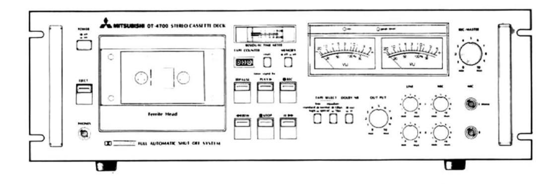
SERVICE MANUAL STEREO CASSETTE DECK MODEL DT-4700
CONTENTS
| 2 | |
|---|---|
| MECHANICAL PERFORMANCE | 3 |
| ELECTRICAL PERFORMANCE | 3 |
| FREQUENCY CHARACTERISTIC TABLE | 4 |
| SERVICING NOTES | 5 |
| DISASSEMBLING OF COMPONENT PARTS | 6 |
| ADJUSTMENT OF MECHANICAL PARTS1 | 5 |
| ELECTRICAL ADJUSTMENT1 | 7 |
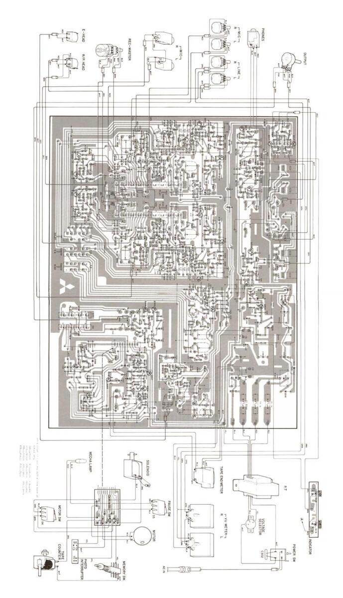
| WIRING AND PRINTED CIRCUIT BOARD DIAGRAM2 | 3 |
| CIRCUIT DIAGRAM | 5 |
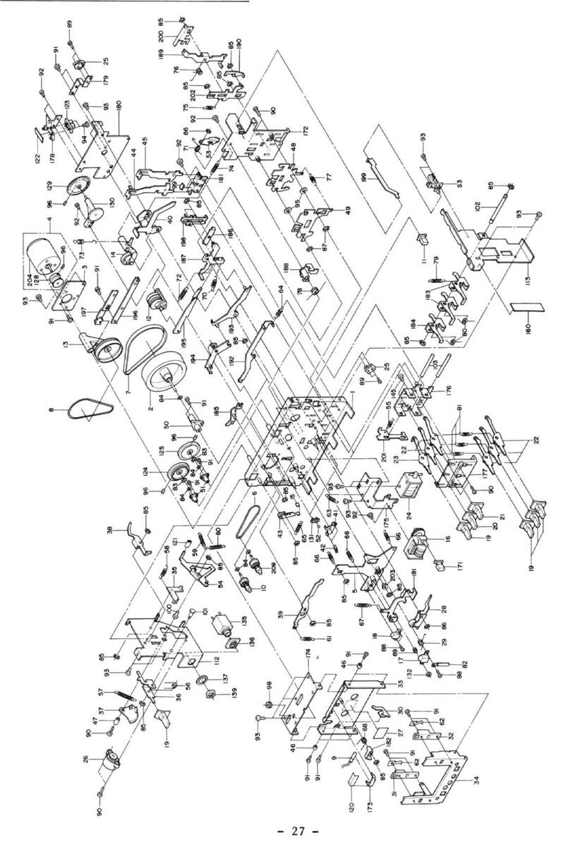
| EXPLODED DIAGRAM OF MECHANICAL PARTS2 | 7 |
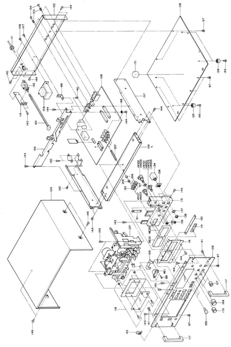
| EXPLODED DIAGRAM OF CABINET | 8 |
| PARTS LIST | 9 |
MITSUBISHI ELECTRIC CORPORATION
Normal is Special tape is = . (Special tape includes DIATONE X, TDK SA, and MAXELL UDXL-II.) Tapes to be used for recording and reproducing are TDK AC-211 (Normal) and TDK AC-511 (Special). SPECIFICATIONS Noise reduction system: Dolby NR Tracks: 4-track, 2-channel Tape speed: 4.75 cm/sec. TDK AD (Normal position) Recommended type of cassette: TDK SA (Special position) Recording system: AC bias (85 kHz) Erasing system: AC erasing (85 kHz) Playback equalization: Normal position 3,180µsec./120µsec. 3,180µsec./70µsec. Special position Input level and impedance: MIC 0.3 mV/2.2 kohms LINE 80 mV/90 kohms DIN 5.6 mV/8 kohms Output level and impedance: LINE 0.44V/22 kohms HEADPHONE 0.8 mW/8 ohms DIN 0.44V/22 kohms Motor: DC servo motor with tachogenerator Magnetic heads: Record/Playback Ferrite Erase Ferrite Wow and flutter: 0.06% (Wrms) ± 0.12% (Wp-p, DIN) Signal to noise ratio: Weighted Dolby NR out 56 dB (RMS) 49 dB (DIN) Weighted Dolby NR in 64 dB (RMS) Frequency response: Normal position 40 Hz to 13 kHz Special position 40 Hz to 16 kHz Power consumption: 11W Dimensions (W × H × D): 480 × 154 × 310 mm (18-7/8 × 6-1/16 × 12-3/16") Weight: 9.5 kg (21 lb)
(Note)
TAPE SELECT part is classified
as follows:
"DOLBY" and the Double D symbol " T are trademarks of Dolby Laboratories. Design and specifications are subject to change without notice for improvement.
MECHANICAL PERFORMANCE
| Tape Speed | 3000 Hz ±60 Hz | Within 0.4 sec. at rising-up time of | |||||
|---|---|---|---|---|---|---|---|
|
Tape Speed
Variation |
Within 30 Hz | PAUSE |
tape in PAUSE/OFF position
Within 4 sec. at rising-down time of tape in PAUSE/ON position |
||||
| Wow & | Under 0.18% rms in | D. J. Dutter | PLAY | 1.8 | STOP | 1.5 |
Counter,
reset 0.8 |
| Flutter | reproducing type | Force | REC | 1.5 | EJECT | 1.5 | |
| FF/REW | 100 sec. at C-60 | FF | 1.5 | PAUSE | 1.5 | (Under kg.) | |
|
Numbers on
Counter |
534 30 at C-90 |
Pinch Roller
Pressure |
400 g | ±50 ( | a | ||
|
End-Stop
Working |
Within 5 sec. | REW Force |
PLAY 40 to 60
FF, REW 105 to 165 (g/cm) |
cm) | |||
ELECTRICAL PERFORMANCE
| and a second | ||||||
|---|---|---|---|---|---|---|
| Max. Output Level |
-5.5 dB(V) +1 dB
-2 dB LINE-IN -22 dB(V) ±3 dB MIC -72 dB(V) ±3 dB |
Bias Leak | LINE-IN: Under -50 dB(V) | |||
| MIC: Under -40 dB(V) | ||||||
| Max. Input Level | Between | Over | 30 dB at 1 kHz | |||
| channels | over | 25 dB at 500 Hz to 6.3 kHz | ||||
|
Reference Output
Level |
Reproducing
system |
LINE-QUT -7 dB(V) ±1 dB
HEAD, PHONE -21 db(V) ±½ dB |
Between |
Over
60 dB |
40 dB at 125 Hz and
at 1 kHz |
|
|
Overall LINE-OUT -7 dB(V) ± 2 dB
(TDK AC-221 tape for |
tracks |
Over
6.3 k |
45 dB at 500 Hz to
Hz |
|||
| system | measurement) | Click Noise | Under -30 dB(V) | |||
| Reproducing | Within 1 dB at 400 Hz | Bias Frequency | 85 kHz ±5% | |||
|
Level Variation
between Channels |
system Within 3 dB at 40 Hz to
6.3 kHz |
- Distortion
Factor |
Under 2.5% in TDK AC-221 tape for measurement | |||
|
Overall
system Within 1 dB at 400 Hz Within 3 dB at 40 Hz to 6.3 kHz (TDK AC-221 tape for measurement) LINE-IN: within 2 dB |
Under 3.0% in TDK AC-511 tape for measurement | |||||
| Dolby Effect | Over 8.5 dB in TDK AC-221 tape for measurement | |||||
| Min. Input | Mixing | Within 1 dB in level variation | ||||
| Level | MIC: within 2 dB | Peak Level | Under +4 dB at lighted level | |||
|
Reproducing
system +3 VU ±1 VU Reading bet- ween channels Within 1 VU |
Indicator | Over 0 dB at lighted-out level | ||||
|
Level Meter
Reading |
Noise Level in
ON/OFF of Power Source |
Under -30 dB(V) in recording noise level,
monitor output noise level, and timer re- producing noise level, respectively |
||||
| Reduing | ||||||
| Level Variation | Within 1 VU at 400 Hz |
Meter Reading
Tolerance for Amount of Remain- ing Tape |
When C-60 tape (TDK AC-221) is used | |||
| Within 2 VU at 40 Hz to 6.3 kHz | Meter re | ading |
Actual tape
remaining time |
|||
|
Reproducing
system Over 47 dB |
3 min. | 3 to 3.45 min. | ||||
| S/N ratio | Overall Over 43 dB (TDK AC-221 tape | 5 min. | 5 to 6 min. | |||
| Providence Problem | system for measurement) | |||||
| Erasing Ratio | Over 60 dB (( | closs erasing: within 2 dB) | ||||
FREQUENCY CHARACTERISTIC TABLE
1. Reproducing system Normal position
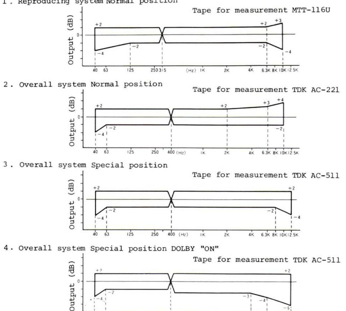
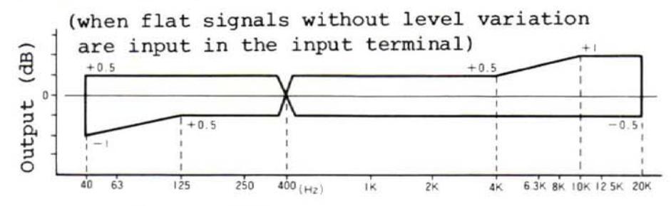
5. Monitor terminal DOLBY NR "ON"
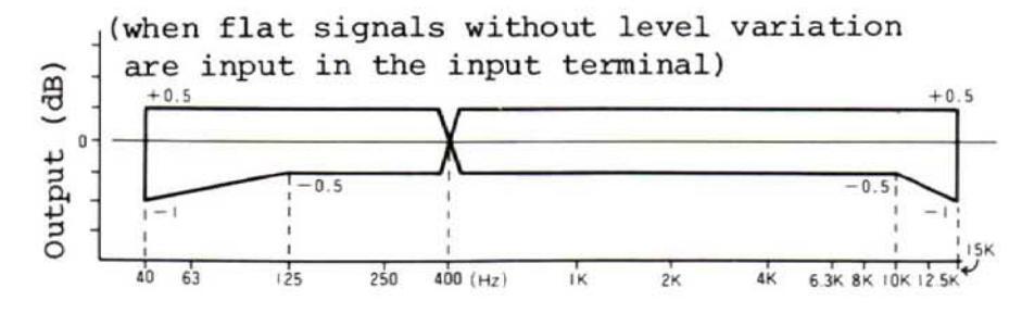
6. Monitor terminal DOLBY NR "OFF"
SERVICING NOTES
- 1. Refer to the Instruction Manual (for operation).
- 2. A number of rubber parts, such as the belt and idler, are used in a tape recorder for purposes of transmitting revolution. The belt, in particular, may not adequately durable on account of the manner of its application. Be sure to check whether it should be replaced or not at the time of servicing.
- 3. Unlike other audio products, the tape recorder is equipped with a mechanism. And no matter how excellent the electric circuit characteristics may be, the functions of the mechanism cannot be exploited fully unless tape transport is perfect during PLAY. Inadequte adjustments related to the tape transport system may result in serious troubles, such as revolution drift, unstable tape speed and deterioration in electric circuit characteristics arising from instability of tape-head contact. In servicing, therefore, make adjustments or repairs while paying close attention to the points given below.
- 4. Use special care in handling the capstan and the head, as tape recorder components generally have many precision-finished portions.
- 5. Demagnetize each head before making adjustment with the standard tape. Note: Use case as the REC/PLAY head is magnetized when metered with a resistance meter like tester or vacuum tube voltmeter.
- Demagnetize the head before using metal tools near it for purposes of repair or adjustment.
- 7. Keep the head surface free of magnetic particles scraped off the tape and dust (use absorbent cotton or gauze impregnated with the head cleaning solution or alcohol to clean the head).
- 8. Be sure power supply voltage is normal (low power supply voltage leads to deterioration in reproduced sound quality because of slowed-down tape speed and increased wow and flutter and amplifier distortion)
- 9. Wipe off oil dregs before lubricating, and then give one to two drops of General Oil's GEMICO TL (TAPINOL #30) to the rotary shaft and apply a small amount of Toho Polymer's FL-LUBEA (white) to the sliding faces.
- 10. Be sure to lock securely the cover of the cassette case when the various characteristics are to be measured.
- 11. Clean any stain on the cabinet with a neutral detergent.
DISASSEMBLING OF COMPONENT PARTS
Precautions
- 1) Refer to the disassembling diagram at the end of this manual.
- 2) Be careful not to allow oil stick to the revolution transmission unit during disassembling. If any happens to stick, thoroughly clean it off with alcohol or the like before reassembling.
- 3) As oil or grease is applied to the removed parts, especially to mechanical parts, be careful not to let nay foreign matter stick to them.
- 4) Be sure to use specified screws when assembling, as use of screws not specified may lead to cracking of shaped articles, failure to fix the parts or demolishing of the screw thread.
- 5) Avoid marring the top panel and the meters.
- 6) Put all the removed screws and knobs in a small box or the like together so as not to lose them.
- 7) As screw locking agent is used for the screws of the mechanism unit to prevent them from becoming loose, apply a drop or two of solvent like thinner when the screws of that unit are to be removed. Then making sure that the screw lock has been softened after a few minutes, unscrew them with a screw driver that fits the screw heads perfectly. (avoid letting the solvent to stick to any part using plastic as it is corrosive)
8) As the disassembling method is described in the order of stops to be taken from the beginning, use it as a reference.
Be sure to achieve correct reassembling by following the stops taken in reverse order.
DISASSEMBLY
1. Removing Cassette Cover
The cassette cover can be removed by placing both thumbs on the cassette guiding groove of the cassette case and lifting the lower part of the cassette cover with other fingers.
- * ASSEMBLY: Fit the two small protrusions on the bottom of the cassette cover in position and then push them closely into the cassette case proper.
- 2. Removing the Upper Cover
The upper cover can be removed by taking out four screws (M4 x 0.7 x 5) on both sides of the cassette cover.
3. Removing the Lower Cover
The lower cover cna be removed by taking out screws (tapping 3 x 8) from (1) ~ (9) shown in Fig. 1.
The patter part may be checked in this state.
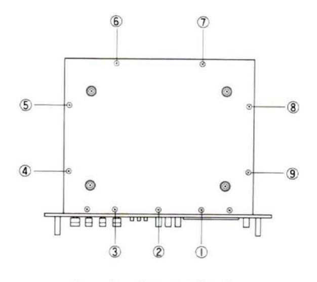
Fig. 1 (Rear View)
-
4. Removing the Front Panel
- a. Remove the cassette and upper covers in accordance with above-mentioned procefure 1 and 2.
- b. Remove six VR knobs.
- c. Separate the power switch part from the push button part and take out the push button part.
- d. Fig. 2 show the upper panel surface
Screws from 1 to 3 (tapping 3 x 6)
Screws from 4 to 7 (M3 x 0.5 x 6)
Note: Care should be taken since the clamping board is removed if 6 and 7 are taken out.
Fig. 2 shown the lower panel surface
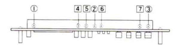
(Upper Panel Surface)
(Lower Panel Surface)
Fig. 2
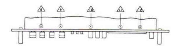
If all screws from 8 to 12 are taken out, the front panel may be removed.
- Note: Care should be take since the push button of the tape ocunter is removed when taking out the front panel.
- * ASSEMBLY: Before assembly, be sure to confirm theat the push button is pushed in its operable position.
- 5. Removing MIC Jack, Volume and Meter
Each clamping screw should be removed from each part after following abovementioned procedure 4.
6. Removing LED (for REC, PEAKLEVEL Indication)
The LED is soldered to the small printed circuit board which is bonded to the holder (aluminum board) of the level meter.
The LED can be replaced if the printed circuit board may be removed properly after removing the upper cover. But it can be removed with ease and properly when the front panel and screw (tapping 3 x 6) of the level meter holder are taken out.
To remove the bonded PC board, a few drops of thinner are pured into the bonded section and take it out with the tip of a screw-driver after checking to see that the bonded section has softened.
* ASSEMBLY: Be careful about the polarity of the LED. (The appearances and polarity of the LED are given in the CIRCUIT DIAGRAM on last page.)
7. Removing Mechanical Part
- a. Remove the front panel in accordance with the foregoing procedure 4.
- b. Remove the bound sections from A to H shown Fig. 3. (The remaining lines except for mechanical parts must be temporarily bound.)
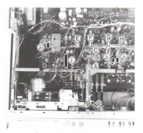
Fig. 3
c. Remove (J) and (J) to (J3) shown in Fig. 3.
Colors of Jack
|
Color of
shielding wire |
Color of the
mid-part of the Jack |
Circuit to be
connected |
|
|---|---|---|---|
| Jı | Gray | White |
Recording and play-
back head LCH |
| J2 | Gray | Red |
Recording and play-
back head RCH |
| J 3 | Gray | Black | Erasing head |
- d. Remove screws (tapping 3 x 6) from (1) to (2) shown in Fig. 3.
- e. Remove the spring between REC and SW by lifting the mechanical assembly.
- f. If the headphone jack under the left lower part of the mechanical assembly is taken out, the mechanical assembly can be separated.
-
* In assembly, pay attention to the following:
- 1) Put the spring linking REC and SW and check the lever for operation. Thus assembly must be started.
- 2) As shown in Fig. 4, link the PC clamping screw to the spring. (Two sections)
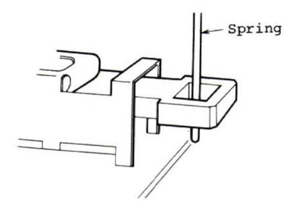
Fig. 4
8. Removing Headphone Jack
Remove the screws from (1) to (2) shown in Fig. 3 and slide the mechanical assembly, and it can be taken out.
9. Removing Mechanical Parts
Note: This section deals with the removal of the mechanical parts with starting the state of the mechanical assembly being taken out explained in procedure 7.
1) When removing parts on the upper part of the mechanical base:
Remove three holder (cassette case) clamping screws (M2.6 x 0.45 x 4), take out the lever connection on the left of the case, and the case is removed. Thus the parts on the upper part of the mechanical base.
-
2) When removing parts on the lwoer part of the mechanical base:
- a. When removing the holders (motor) and (flywheel) shown in Fig. 5, the spring (motor) in Section A and the springs in Section (flywheel) B and C must be removed.
- b. Loosen the rotary shutter in Fig. 5 with a hexagonal monky wrench (1.3 mm) and remove screws (M3 x 0.5 x 4) from 1 to 2 shown in Fig. 5. As soon as the holder (flywheel) is removed, the rotary shutter is removed.
- c. The holder (motor) can be removed by taking out two screws (M2 x 0.5 x 4).
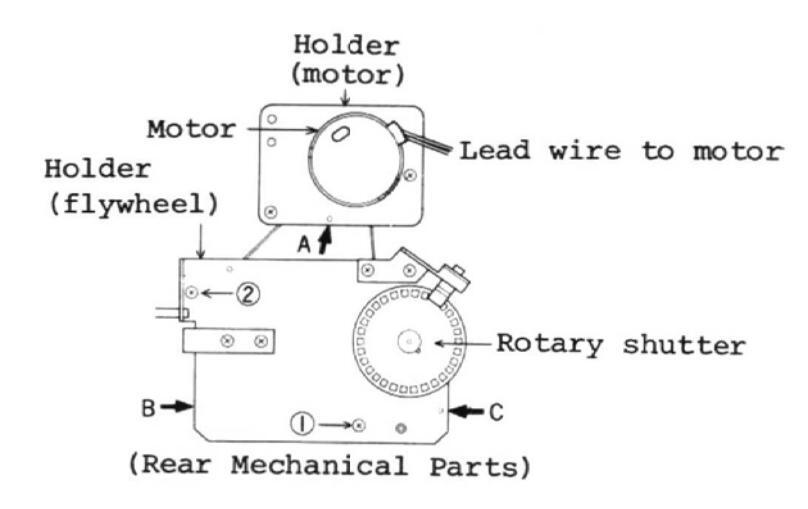
Fig. 5
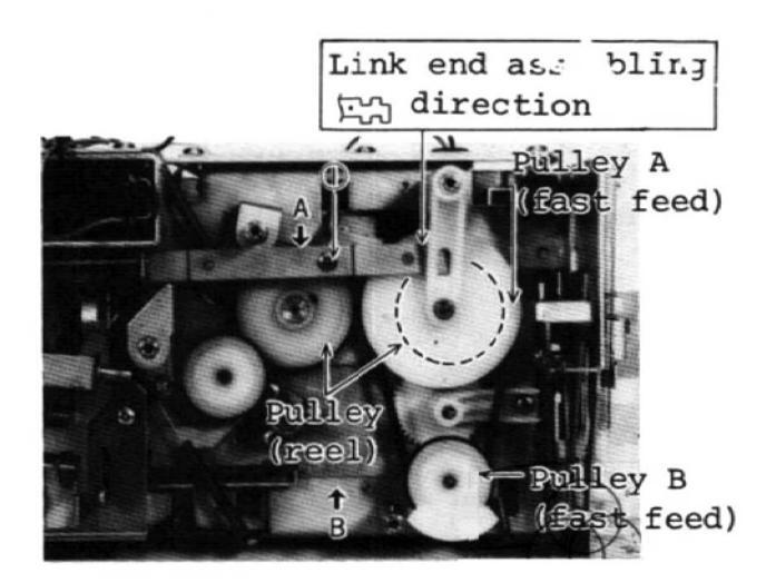
- d. Fig. 6 shows how the flywheel and holder (motor) has been disassembled. For further disassembly, Link A can be disassembled into two parts and Pulley A can be removed if screw (1) (M2.6 x 0.45 x 5) in Fig. 6 is loosened.
-
* Before assembly, pay attention to the following:
- o Set the end of the Link A in the direction on the right upper portion of Fig. 6.
- o Insert the shaft of the Pulley B in to the end hole of the Link B shown in Fig. 6.

e. Removing Reel Shaft and Pulley (Reel)
Remove Pulley A and the pulley (reel) clamping screw with the hexagonal monkey wrench (1.3 mm) following the foregoing procedured. The Reel shaft is taken out by removing the E ring (E2).
-
3) When the mechanical push button part, this is the procedure.
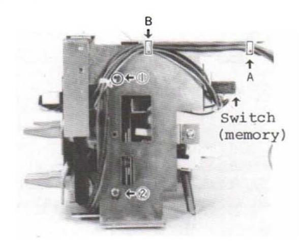
- a. Remove the A and B on the right of Fig. 7.
- b. Remove the screws (M3 x 0.5 x 4) from (1) to (2) shown in Fig. 7.
- c. Remove the link attached to the switch (memory) illustrated on the right upper side of Fig. 7. Remove the right board after taking out the two switch (memory) clamping screws (M3 x 0.5 x 4).
(Right Mechanical Parts)
Fig. 7
- d. Remove the solenoid by taking out the two solenoid clamping screws (M3 x 0.5 x 4).
- * Cautionary Instructions for Assembly
Note: Be sure to use M3 x 0.5 x 4 screws for clamping the solenoid.
- For solenoid assembling position adjustment, refer to the paragraph of "Adjustment of Mechanical Parts".
- e. To remove the holder, take out the two screws (M2.6 x 0.45 x 4) clamping the holder (flywheel).
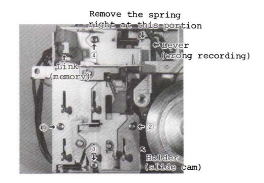
Fig. 8 (Rear Push Button Part)
f. Remove screws (M2.6 x 0.45 x 1.2) from 1 to 2 and those (M2.6 x 0.45 x 5) on the rear of the push button given in Fig. 8 and the push button part by taking out the button on the tip of the link (memory) and the link. If the spring shown on the right upper portion of Fig. 8 is removed on the lever side, the holder (slide cam) can be disassembled.
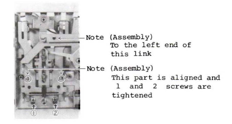
Fig. 9
Remove the spring right at this portion
Fig. 10
g. Remove the screws (2.6 x 0.45 x 5) from (1) to (2) shown in Fig. 9.
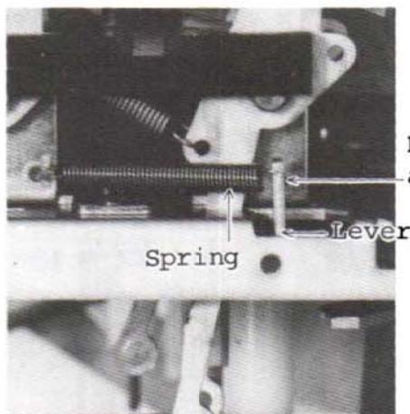
h. Remove the spring shown in Fig. 10 on the lever side.
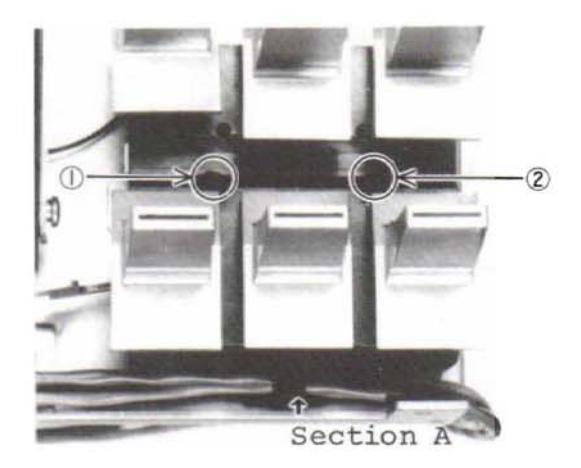
Fig. 11
i. Remove the three shielding wires supported in Section A in Fig. 11 from its supporting part.
Remove the screws (2.6 x 0.45 x 12) of Fig. 11.
Thus the upper part of the mechanical base of the push button part can be taken out.
4) For further disassembly of the push lever part, it can be disassembled by taking out the screws (tapping 3 x 10) shown in Fig. 12 after finishing the procedures given in Item 3).
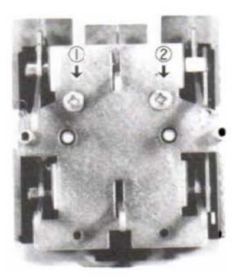
Fig. 12
To replace the mechanical push button (lever) assembly, the assembly must be disassembled into a single lever unit in accordance with the prodedure 4). (EJECT Button is exception.)
10. How to Replace the Mechanical Push Button Part (Stock Item) (Mechanical Disassembly Drawing No. 19 to 21)
When a button breaks and it must be replaced, replace it in the following manner.
-
a. The EJECT button can be replaced with the mechanical assembly being taken out.
- b. The other lever buttons for mechanical units must be taken out with the button being adhered to the push button lever following the steps given in the above-mentioned Paragraphs from 1) to 4).
- c. As soon as the button side of the metal lever part to be replaced is heate hot with a soldering iron, the button part is taken out.
- d. When the button is removed, wipe off dirt on the metal lever.
- e. Bond a new button to the metal lever.
Use an epoxy adhesive.
-
Note 1) The button must be bonded in line with the other button part.
- Care should be taken not to let the adhesive flow into the mechanical parts until it has set.
ADJUSTMENT OF MECHANICAL PARTS
-
1. Solenoid Assembling Position
- a. Pinch lever pressure
- b. Be sure to use a screw of 4 mm long as a solenoid clamping screw (M3x0.5x4). The solenoid is temporarily clamped with this screw so that it can be moved back and forth.
- c. Put the solenoid between fingers in the A and B direction shown in Fig. 13 and place it as much close as possible towards direction.

Fig. 13 (Solenoid Part)
2. Pinch Lever Pressure
Measurement is made by applying the end of the tension gauge at right angle against measurement direction, in the direction linking the capstan shaft and the pinch roller shaft in straight line.
400 g ±50 g (See the mechanical performance)
-
3. Back Tension
- a. When the felt is dirty, replace it (There are service parts available and it is bonded.)
- b. Put the spring (back tension) onto the position No. 3 given in the lever.
-
4. PALÝ, FF, and REW Measurement
- a. Measure with the cassette for measureing REW.
- b. Measure with torque dial gauge for measuring rotation.
REW force PLAY 40 to .60 g/cm FF, REW 105 to 165 g/cm (See the mechanical performance.)
-
5. Motor Replacement and Speed Adjustment
- a. The motor must be installed so that the leading wire to the motor can be out in the direction shown in Fig. 5.
- b. Speed is adjusted in accordance with the step described in Fig. 14. The tape to be used is MTT-111 (3000 Hz). 3000 Hz ±60 Hz (See the mechanical performance.)
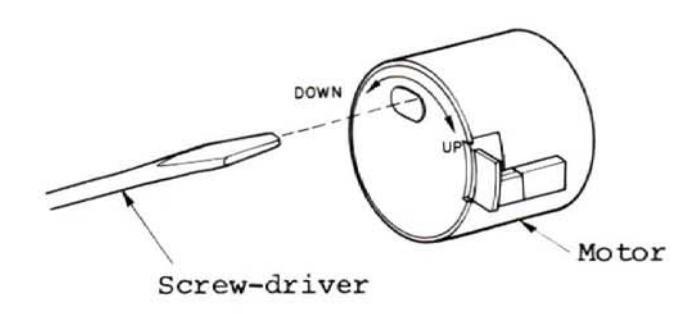
Fig. 14
6. Head Angle Adjsutment
When the recording and playback head is replaced or moved at a wrong angle, use the tape MTT-115 (333/6.3 kHz) for measurement or MTT-115C (330/10 kHz) and set a playback output of the higher frequency at the maximum position in L and RCH together.
(Screws must be locked after adjsutment.)
ELECTRICAL ADJUSTMENT
- Undertake adjustment when necessary after parts replacement and so forth.
-
Instrument Used
- Low-frequency oscillator: 20Hz 20kHz Variable resistance attenuator: 0 90dB or 0.1 or 0.5dB step AC voltmeter: 20Hz 100kHz or more, input impedance of 100kΩ or more, capable of measuring down to -60dB(V) Vacuum tube voltmeter: for DC voltage measurement
- 5) Frequency counter
- 6) Oscilloscope
- 7) Test tapes
- Output Unit Connection
For each of L and R channels connect a 22kΩ resistor as shown in Fig. 15 and undertake adjustment (the reason is to make the output level proper).

Fig. 15
- Unless otherwise specified, leave TAPE SELECT on the NORMAL side and DOLBY NR on the OUT side during adjustment.
- Selection of AC Power Source (Primary Side)
When AC power source is 240 V, be sure to use the voltage selector attached to this set in harmony with specified 240 V.
Voltage Selector
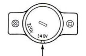
Set the voltage to the position having a cavity.
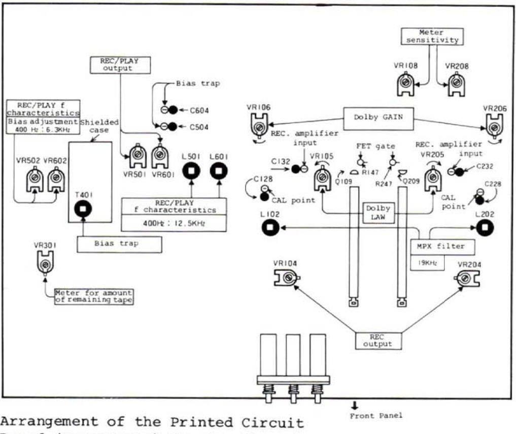
Board (Components) Showing Where to be Adjsuted
Fig. 16
CIRCUIT ADJUSTMENT
-
Note 1) Before adjustment, check to see that the head angle is right and has been cleaned well.
- Unless otherwise specified, take the following steps in turn to make adjustments.
- 3) Try to adjust VR starting with approximately the center of the adjustable range.
- When the REC/PLAY head is replaced, all the adjustment steps mentioned below must be taken.
- 5) When the erasing head is replaced, the bias trap, REC/PLAY f characteristics and REC/PLAY output must be adjusted.
| Step | Adjustment | Adjusting Points | Adjusting Method | |||
|---|---|---|---|---|---|---|
|
VR104(L)
VR204(R)Play back the ing output lev CAL Point to b1Play output(Detection Position) Between - pole of C128 (L) and CAL Point and earthNote: As the above set. |
VR104(L)
VR204(R) |
|
||||
| 1 |
Note: As the error measured in the
above CAL point becomes double if recorded and played at Dolby IN, it must be correctly set. |
|||||
| 2 |
Meter
Sensitivity |
VR108(L)
VR208(R) |
|
|||
|
T401
(in shielded case) • Set the machine in a record • Connect the DC voltmeter b |
||||||
| 3 | Bias trap |
(De
Bias trap Po Bet of C60 ear |
(Detection
Position) Between - poles of C504 (L) and C604 (R) and earth |
and set the voltage values of L and R
to a minimum (Consider the balance of L and R). [The voltage is about 1 to 0.2 V.] |
||
| 4 |
Steps 5 and
6 must be followed |
|
to
ion) |
|||
| • Follow the Step 4. | up | |||||
|
REC/PLAY
characteristics (See Fig. 18) |
(Bias adjustment)
VR502(L) VR602(R) |
|
l position | |||
| 5 |
|
ecia | ||||
|
L501(L)
L601(R) |
|
is made at Sp | ||||
| VR-501(L) |
|
stment | ||||
| 6 | REC/PLAY Output | VR-601 (R) |
as the output (monitor level) of LINE
OUT at 400 Hz while being recorded. (Dectect at LINE OUT.) |
Adjus
+hece |
||
| Step | Adjustment | Adjusting Points | Adjusting Method |
|---|---|---|---|
| 7 | MP Filter |
L102(L)
L202(R) |
|
| 8 | Dolby circuit |
GAIN VR
VR106(L) VR206(R) LAW VR VR105(L) VR205(R) Detection position CAL Point (See Step 1) Detection position REC. ampli- fier input Between- pole sides of C132(L) and C232(R) and earth |
|
| 9 |
Meter for
amount of remaining tape |
VR301
(Set at 3010 Hz) |
|
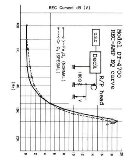
Fig. 18
- 21 -
- 22 -

- 23 -
- 24 -
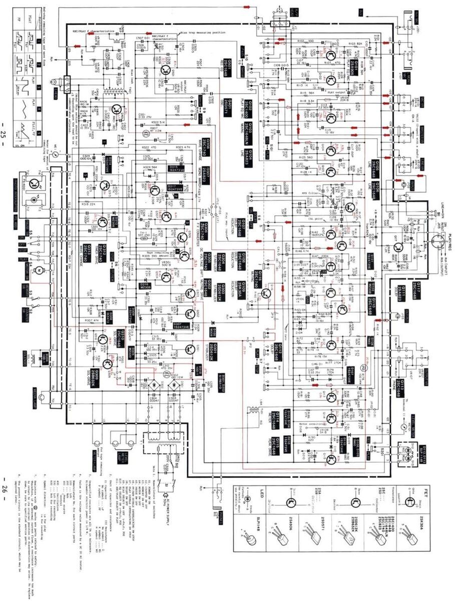
CIRCUIT DIAGRAM
EXPLODED DIAGRAM OF CABINET
PARTS LIST
| SYMBOL NO. | PART NO. | DE | SCRIPTION |
|---|---|---|---|
| D101 | м07060320 | Diode | 1S2473VE |
| D102 | M07133322 | n | MZ308 |
| D103.D203 | M07060320 | 1S2473VE | |
| D104.D204 | |||
| D105 | M05139320 | MZ306 | |
| D106 D206 | M04097320 | 1N60 | |
| D107 D207 | M07060320 | 1S2473VE | |
| D108 D208 | M04097320 | 1N60 | |
| D109 D209 | " | " | |
| D100,0200 | M07060320 | 1S2473VE | |
| M05129321 | LE Diode | SLP-114B | |
| D112,D113 | NOSIZJOZI | ||
| 1050 | M07151320 | Diode | S1RBA10 |
| D302 | " | ||
| D304 | M04079320 | 10D1 | |
| D305 | M07140320 | MZ320 | |
| D307 | M07060320 | н | 1S2473VE |
| D308 | " | " | |
| D308 | " | ||
| 13 | M07133322 | MZ308 | |
| D314 | M07060320 | 1S2473VE | |
|
D314
D315 |
" | ||
| D312 | M07133322 | MZ308 | |
| D316 | M07060320 | 1S2473VE | |
| D317 | M0/079320 | н | 1001 |
| D318 | M04079520 | 1001 | |
| 0101,0201 | M05131316 | Transistor | 2SA906 |
| 0102.0202 | M05131315 | 2SC1400 | |
| 0103.0203 | M05104310 | " | 2SC1648 |
| 0104.0204 | M05104312 | 2SA823 | |
| 0105,0205 | M05104310 | 2SC1648 | |
| 0106 0206 | " | " | " |
| 0107 0207 | |||
| 0108 0208 | н | ||
| M07068309 | 2SK30A | ||
| M05104310 | 2SC1648 | ||
| M05104312 | 254823 | ||
| Q111,Q211 | M05104312 | 2501648 | |
| Q112, Q212 | M05104510 | " | |
| Q113,Q213 | |||
| Q114,Q214 | |||
| Q115,Q215 | NOE104212 | 2501740 | |
| Q116, Q216 | MO5104313 | " | 2501740 |
| Q117,Q217 | M05121211 | 2506128 | |
| Q301 | M05151511 | " | |
| 0305 | M05104313 | н | 2SC1740 |
| 0305 | MOJ104313 | " | |
| 0306 | M05104312 | 2SA823 | |
| 2307 | M05104313 | u | 2SC1740 |
| 0300 | M05131312 | н | 2SB632K |
| 0310 | M05104310 | 2SC1648 | |
| Ž210 | 103104310 |
| SYMBOL NO. | PART NO. | DESCRIPTION | ||
|---|---|---|---|---|
| Q311 | M05104313 | Transistor | 2SC1740 | |
| Q312 | ||||
| Q313 | ||||
| Q401 | M07228303 | 2SD571 | ||
| Q501 | M05104310 | " | 2SC1648 | |
| Q601 | п | " | " | |
| rH-1 | M05099330 | Termistor | SDT-250 | |
| R178,R278 | M05129471 | R-Fuse-1/4 | W 100 Ω (~) | |
| R302 | M05067365 | R-Fuse-1/2 | 2W 100 Ω " | |
| R407 | M07113411 | R-Fuse-1/2 | 2W 47 Ω " | |
| VR101,VR201 | M05129350 | VR-STD-A20 | )K25 | |
| VR103, VR203 | " | |||
| VR107,VR207 | M05131350 | VR-W-A20K2 | 25 | |
| VR120,VR220 | M05131351 | VR-W-A10K2 | 25 | |
| тl | M05150410 | Trans Powe | er | |
| Sl | M05113430 | SW Push (F | POWER) | |
| S3 | M05131431 | " (MEMORY) | ||
| S4,S5 (25) | M05129431 | SW-Micro | ||
| S6,S7 | M05085435 | SW Slide | (FF, REW, PLAY | |
| S8,S9,S1 0 | M05131430 | SW Push (I | DOLBY, EQ, BIA | |
| s101,s201 | M05067430 | SW Slide | (R/P) | |
| J101,J201 | M05129447 | Jack (MIC) | ||
| J105 | M05104441 | " (HEAD | PHONE) | |
| MEl | M05131400 | Meter | ||
| ME101, ME201 | M05130400 | " (LEVE | EL) | |
| F1,F2 | M05110472 | Fuse 1A SI | EMKO | |
| F3 | M05110471 | " 800MZ | A SEMKO | |
|
EXPLODED
DIA. NO. |
PART NO. | DESCRIPTION |
|---|---|---|
| 205104500 | ||
| 2 | M05104520 | Flywneel |
| 6 | M05104552 | Belt (COUNTER) |
| 7 | M05131550 | (MOTOR) |
| 8 | M05104550 | " (FF.REW) |
| 9 | M05131490 | Lamp |
| 10 | M05104525 | Reel Rest Ass'y |
| 11 | M05131216 | Knob Ass'y (MEMORY) |
| 13 | M05104543 | Pulley Ass'y (FF/REW) |
| 16 | M05131404 | Counter |
| 17 | M05104830 | Head (REC/PLAY) |
| 18 | M05104831 | Head (ERASE) |
| 24 | M05131390 | Solenoid |
| 26 | M05131621 | Gear Ass'y |
| 28 | M05104544 | Pinch Lever Ass'y |
| 57 | M05131560 | Spring-W (EJECT) |
| 118 | M05150111 | Cover Ass'y |
| 123 | M05131314 | Photo Interrupter PS4001 |
| 124 | M05131540 | Pulley |
| 125 | M05104541 | u l |
| 126 | M07215195 | Leg |
| 127 | M05131212 | VR Knob (LINE, MIC) |
| 130 | M05131620 | Gear Ass'y |
| 164 | M05131213 | Knob Link Ass'y (POWER) |
| 165,205,206 | M07215214 | Knob Ass'y (DOLBY, BIAS, EQ) |
| 169 | M05131210 | VR Knob (REC, MASTER) |
| 170 | M05131211 | " (LINE, MIC) |
| 171 | M05131215 | Knob Ass'y (RESET) |
| 204 | M05149500 | Motor |
| 208 | M05131525 | Reel Rest Ass'y |
| м07050470 | Lead (L+R for Connection Cord) |

DT-4700 IT, NL, SD, SS, UK SM-8021 PRINTED IN JAPAN


 Loading...