

Mitsubishi Electric DPro930SB-BK, DPro930SB-BKAB, DPro930SB-BKA, Diamond Pro 930SB, DPro930SB-BKB Service Manual
Page 1

PART NO. 599910624
COLOR MONITOR Diamond Pro 930SB
MODELS DPro930SB -BK(A)/(B)/-BK(B)
200307
08M530A3
08M540B3
08M530B3
SERVICE MANUAL
NEC-MITSUBISHI ELECTRIC VISUAL SYSTEMS CORPORATION
OCTOBER 2002
Page 2
WARNING
The SERVICE PERSONNEL should have the appropriate technical training, knowledge and
experience necessary to:
• Be familiar with specialized test equipment, and
• Be careful to follow all safety procedures associated with high voltage CRT circuit designs to
minimize danger to themselves and their coworkers.
To avoid electrical shocks, this equipment should be used with an appropriate power code and be
connected only to a properly grounded AC outlet.
This equipment utilized a micro-gap power switch. Turn off the set by first pushing the front panel
power switch. Next, remove the power cord from the AC outlet.
To prevent fire or shock hazards, do not expose this unit to rain or moisture.
This symbol warns the personnel that un-insulated voltage within the unit may have
sufficient magnitude to cause electric shock.
This symbol alerts the personnel that important literature concerning the operation and
maintenance of this unit has been included.
Therefore, it should be read carefully in order to avoid any problems.
Page 3

PRODUCT SAFETY CAUTION
1. When parts replacement is required for servicing, always use the manufacturer's specified replacement.
2. Comply with all caution and safety-related notes on the product display chassis and picture tube.
3. When replacing the component, always be certain that all the components are put back in the place.
4. When servicing display monitor unit, it is required that the provided lead dress is used in the high voltage
circuit area.
5. It is also recommended that shatter proof goggles are worn, when removing installing and handling the
picture tube. People not equipped with the proper precautionary measures mentioned should keep the
picture tube away from body while handling.
6. As for a connector, pick and extract housing with fingers properly since a disconnection and improper
contacts may occur, when wires of the connector are led.
7. Use a proper screwdriver. If you use screwdriver that does not fit, you may damage the screws.
8. X-radiation precaution
This product contains critical electrical and mechanical parts essential for X-ray protection.
Normal anode voltage is 26.0 kV at zero beam picture tube current under AC 100-120V/220-240V input,
and anode voltage must not exceed the voltages shown below under any operation condition.
To measure anode voltage set brightness for very dim picture, and use a high impedance volt meter
between chassis and anode lead and measure high voltage.
If high voltage exceeds the specifications on the chassis schematic diagram, take the necessary
corrective action.
Table MAXIMUM ANODE VOLTAGE
beam current at 0 mA at 0.6 mA at 1.2 mA
A/B Ver. 31.0 kV 30.5 kV 30.5 kV
9. When you degauss the set with an external degaussing coil, you must keep strictly item “ * Notes about
degaussing method “ of ADJUSTMENT Procedures.
Page 4

CONTENTS
Page No.
USER'S MANUAL ------------------------------------------------------------------------------- 1-1
SERIAL NUMBER INFORMATION ---------------------------------------------------------- 2-1
DISASSEMBLY ----------------------------------------------------------------------------------- 3-1
ADJUSTMENT PROCEDURES -------------------------------------------------------------- 4-1
INSPECTION -------------------------------------------------------------------------------------- 5-1
TROUBLE SHOOTING ------------------------------------------------------------------------- 6-1
CIRCUIT DESCRIPTION ----------------------------------------------------------------------- 7-1
REPLACEMENT PARTS LIST --------------------------------------------------------------- 8-1
BLOCK DIAGRAMS ---------------------------------------------------------------------------- 9-1
SCHEMATIC DIAGRAMS --------------------------------------------------------------------- 10-1
PACKING SPECIFICATION ------------------------------------------------------------------- 11-1
Page 5

1-1
User's Manual
1. A Version
www.mitsubishidisplay.com
1
9
"
Diamond Pro 930
SB
18" Viewable Image Size
USER’S MANUAL
Page 6

1-2
Index
Warning.......................................................................................1
Contents ......................................................................................2
Quick Start...................................................................................3
Controls.......................................................................................5
Recommended Use...................................................................... 8
Specifications ............................................................................10
Features ....................................................................................11
Troubleshooting.........................................................................13
References ................................................................................15
Limited Warranty........................................................................16
TCO’95 ...................................................................................... 17
Avertissement............................................................................20
Contenu.....................................................................................21
Mise en marche rapide .............................................................. 22
Commandes ..............................................................................24
Usage recommandé...................................................................28
Fiche technique ......................................................................... 30
Fonctions...................................................................................31
Dépannage ................................................................................ 33
Références ................................................................................35
Garantie limitée .........................................................................36
TCO’95 ...................................................................................... 37
Sicherheitsvorkehrungen ...........................................................39
Page 7
1-3
1
TO PREVENT FIRE OR SHOCK HAZARDS, DO NOT EXPOSE THIS UNIT TO RAIN OR MOISTURE. ALSO, DO NOT USE
THIS UNIT'S POLARIZED PLUG WITH AN EXTENSION CORD RECEPTACLE OR OTHER OUTLETS UNLESS THE PRONGS
CAN BE FULLY INSERTED.
REFRAIN FROM OPENING THE CABINET AS THERE ARE HIGH VOLTAGE COMPONENTS INSIDE. REFER SERVICING
TO QUALIFIED SERVICE PERSONNEL.
WARNING
Canadian Department of Communications Compliance Statement
DOC: This Class B digital apparatus meets all requirements of the Canadian
Interference-Causing Equipment Regulations.
C-UL: Bears the C-UL Mark and is in compliance with Canadian Safety Regulations
according to C.S.A. C22.2 No. 950.
FCC Information
1.
Use the attached specified cables with the
Diamond Pro 930SB-BK
color monitor so as not to
interfere with radio and television reception.
(1)
Please use the supplied power cord or equivalent to ensure FCC compliance.
(2) Shielded captive type signal cable.
Use of other cables and adapters may cause intereference with radio and
television reception.
2.
This equipment has been tested and found to comply with the limits for a Class B digital
device, pursuant to part 15 of the FCC Rules. These limits are designed to provide
reasonable protection against harmful interference in a residential installation. This
equipment generates, uses, and can radiate radio frequency energy, and, if not installed
and used in accordance with the instructions, may cause harmful interference to radio
communications. However, there is no guarantee that interference will not occur in a
particular installation. If this equipment does cause harmful interference to radio or
television reception, which can be determined by turning the equipment off and on, the user
is encouraged to try to correct the interference by one or more of the following measures:
• Reorient or relocate the receiving antenna.
• Increase the separation between the equipment and receiver.
• Connect the equipment into an outlet on a circuit different from that to which the receiver
is connected.
• Consult your dealer or an experienced radio/TV technician for help.
Changes or modifications not expressly approved by the party responsible for
compliance could void the user’s authority to operate the equipment.
If necessary, the user should contact the dealer or an experienced radio/television
technician for additional suggestions. The user may find the following booklet, prepared
by the Federal Communications Commission, helpful: ”How to Identify and Resolve
Radio-TV Interference Problems.“ This booklet is available from the U.S. Government
Printing Office, Washington, D.C., 20402, Stock No. 004-000-00345-4.
CAUTION
RISK OF ELECTRIC SHOCK • DO NOT OPEN
CAUTION: TO REDUCE THE RISK OF ELECTRIC SHOCK, DO NOT REMOVE COVER (OR BACK). NO USER
SERVICEABLE PARTS INSIDE. REFER SERVICING TO QUALIFIED SERVICE PERSONNEL.
This
symbol warns user that uninsulated voltage within the unit may have sufficient magnitude to cause
electric shock. Therefore, it is dangerous to make any kind of contact with any part inside this unit.
This symbol alerts the user that important literature concerning the operation and maintenance of this
unit has been included. Therefore, it should be read carefully in order to avoid any problems.
Page 8

1-4
2
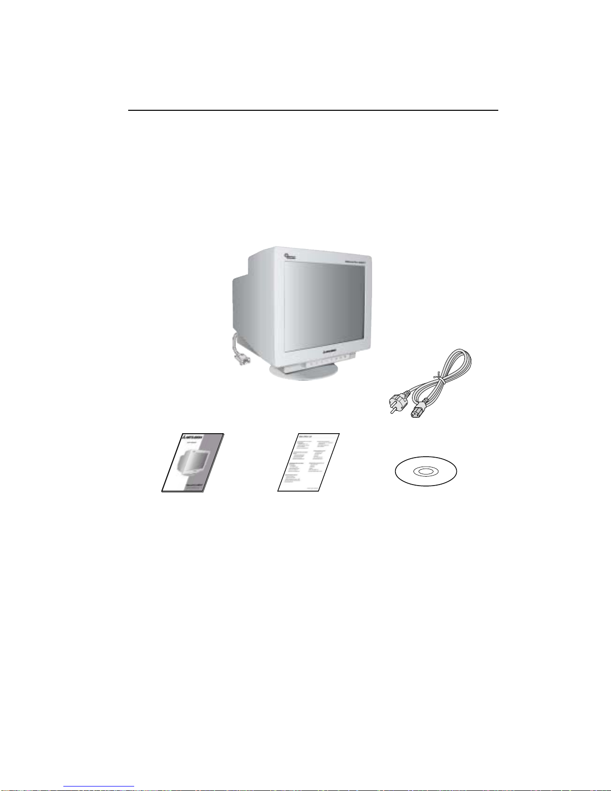
Your new Diamond Pro 930SB monitor box* should contain the
following:
• Diamond Pro 930SBMonitor with tilt/swivel base
• Power Cord
• Captive Signal Cable
• User’s Manual
Contents
Power Cord
User’s Manual
* Remember to save your original box and packing material to transport or ship the monitor.
Captive Signal Cable
Page 9

1-5
3
Quick Start
Figure A.1
To attach the Diamond Pro monitor to your system, follow these
instructions:
1. Turn off the power to your computer.
2. If necessary, install the display card into your system. For more information,
refer to the display card manual.
3. For the PC: Connect the 15-pin mini D-SUB of the captive signal cable to the
connector of the display card in your system (Figure A.1). Tighten all screws.
For the Mac: Connect the Diamond Pro Macintosh cable adapter (not included) to the monitor connector on the Macintosh (Figure B.1). Attach the
15-pin mini D-SUB end of the captive signal cable to the Diamond Pro
Macintosh cable adapter on the computer (Figure B.1). Tighten all screws.
NOTE: To obtain the Diamond Pro Macintosh cable adapter, call
NEC-Mitsubishi Electronics Display of America, Inc. at (800) 632-4662.
4. For download information on the Windows
®
95/98/Me/2000/XP INF file
for your Diamond Pro monitor, refer to the References section of this User’s
Manual.
5. Connect one end of the power cord to the Dimond Pro monitor and the other
end to the power outlet (Figure C.1).
6. Turn on the monitor (Figure D.1) and the computer.
NOTE: If you have any problems, please refer to the Troubleshooting section of
this User’s Manual.
Figure B.1
Captive Signal Cable
Captive Signal Cable
15-pin
mini
D-SUB
Mac Adapter
(Not Included)
Page 10

1-6
4
Quick Start –continued
Figure D.1
Power
Cord
Figure C.1
Power Button
Power Indicator
Page 11

1-7
5
Controls
OSD™ (On-Screen Display) control buttons on the front of the monitor function
as follows:
Main Menu Sub-Menu
EXIT Exits the OSD menu. Exits to the OSD controls
main menu.
NOTE:
Deactivates the OSD menu and activates the OSD menu when the OSD is turned off.
CONTROL Moves the highlighted Moves the highlighted area
area left/right to select left/right to select one of the
one of the sub-menu. controls.
NOTE:
When the OSD menu is off, CONTROL acts as a Hot key for Brightness.
CONTROL Has no function Moves the bar in the – or +
-/+ direction to decrease or
increase the adjustment.
NOTE:
CONTROL button will act as a “Hot Key” for Contrast when the OSM is off and Hot Key is on.
SELECT/ While in OSD, this will enter the Has no function.
SBMODE sub-menu. If OSD is off, this button
will turn on the SuperBright function.
NOTE: When the OSD is off, it will act as the SuperBright (SB) function key.
User can select between SB MODE OFF, SB MODE1, and SB MODE2. The first
time this key is pressed, the current SB Mode is indicated. Within a 3 second
window, if this key is selected again, the SB MODE will change to the next SB
MODE. For example, the current mode is SB MODE OFF, the key is pressed
twice within a 3 second time frame, the SB MODE will change to SB MODE1
and so on. The color temperature at each SB Mode is adjusted by appropriate
color control except for the sRGB mode whose color setting cannot be adjusted.
When the unit is turned off, it will reset to SB off mode.
RESET Resets all the controls within the high- Resets the highlighted control to
lighted menu to the factory setting. the factory setting.
NOTE: When RESET is pressed in the main and sub-menu, a warning window
will appear allowing you to select the reset function.
Brightness/Contrast Controls
Brightness: Adjusts the overall image and background screen brightness.
Contrast: Adjusts the image brightness in relation to the background.
Degauss: Eliminates the buildup of stray magnetic fields which alter the correct scan of the
electron beams and affect the purity of the screen colors, focus and convergence. When
activated, your screen image will jump and waver a bit as the screen is demagnetized.
NOTE:
Please allow a minimum of 20 minutes to elapse between uses of the Degauss Control.
Size and Position Controls
Left/Right: Moves the image horizontally (left or right).
Down/Up: Moves the image vertically (up or down).
Narrow/Wide: Decreases or increases the horizontal size of the image.
Short/Tall: Decreases or increases the vertical size of the image.
Page 12

1-8
6
Controls –continued
Color Control/AccuColor®Control System
Color presets 1 through 5 selects the desired color setting. The bar is replaced by the
color setting choice from 1, 2, 3, sRGB, 5. Each color setting is adjusted at the factory to
the stated Kelvin degrees. If a setting is adjusted, the name of the setting will change from
Kelvin to Custom. NOTE: sRGB does not allow you to adjust each color.
Red, Green, Blue: AccuColor Control System decreases or increases the monitor’s red,
green or blue color guns depending upon which is selected. The change in color will
appear on screen and the direction (decrease or increase) will be shown by the bars.
sRGB mode: sRGB mode provides the suitable color managed picture image. You
can not change Red, Green and Blue colors, brightness and contrast individually.
Color Temperature Adjustment: Adjusts the color temperature of the screen image.
Geometry Controls
Geometry Controls Menu
The Geometry controls allow you to adjust the curvature or angle of the sides of your display.
In/Out (pincushion): Decreases or increases the curvature of the sides either inward or
outward.
Left/Right (pincushion balance): Decreases or increases the curvature of the sides either to
the left or right.
Tilt (parallelogram): Decreases or increases the tilt of the sides either to the left or right.
Align (trapezoidal): Decreases or increases the bottom of the screen to be the same as the top
.
Rotat
e (raster rotation): Rotates the entire display clockwise or counterclockwise.
Corner Correction: Allows you to adjust the geometry of the corners of your display
—
Top or Bottom.
Tools 1
Moiré Canceler: Moiré is a wavy pattern which can sometimes appear on the screen. The
pattern is repetitive and superimposed as rippled images. When running certain applications,
the wavy pattern is more evident than in others. To reduce moiré, adjust the level by using the
–/+ CONTROL buttons.
Linearity: This selection allows you to adjust the spacing of the area on the screen. The
purpose of this control is to ensure that a one-inch circle is a true one-inch circle wherever
it is on the screen. The best way to determine the vertical linearity is as follows:
• Draw equally spaced horizontal lines using a drawing application that has a ruler.
• Use the Vertical Balance control to adjust the lines near the top and bottom of your screen.
• Use the LINEARITY (VER.) control to adjust the spacing between the lines near the center and
top of your screen.
Convergence: Aligns all three colors (R,G,B) to form a single color (white). The purpose of
this control is to ensure that a white line drawn on the screen is as crisp and clear as
possible
.
•
Use the CONVERGENCE (HOR.) control to adjust the alignment of the white lines in the
left/right
direction.
• Use the CONVERGENCE (VER.) control to adjust the alignment of the white lines in the
up/down
direction.
Page 13

1-9
7
Controls –continued
GlobalSync® Control: Eliminates picture impurities that may result from the
earth’s magnetic field. While in the sub-menus (TL: Top Left, TR: Top Right, BL:
Bottom Left, or BR: Bottom Right) use the –/+ control buttons to fine tune the
GlobalSync corrections.
NOTE: Mitsubishi recommends that you perform GlobalSync correction while
running a typical application such as a spreadsheet or text document.
Tools 2
Language: OSD controls menus are available in six languages.
OSD Position: You can choose where you would like the OSD controls menu to
appear on your screen. Selecting OSD Position allows you to manually adjust the
OSD controls menu left, right, up or down.
OSD Turn Off: The OSD controls menu will stay on as long as it is in use. In the
OSD Turn Off sub-menu, you can select how long the monitor waits after the last
touch of a button for the OSD controls menu to disappear. The preset choice is in
5 seconds step between 5–120 seconds.
O
SD Lock Out: This control completely locks out access to all OSD controls func-
tions except Brightness and Contrast. When attempting to activate OSD controls
while in the lock out mode, a screen will appear indicating that OSD controls are
locked out. To activate the OSD Lock Out function, press SELECT, then press + and
hold down simultaneously. To deactivate the OSD Lock Out, press SELECT, then
press + and hold down simultaneously.
IPM™ System Off Mode:
Enable: The IPM System works normally and all
stages of energy savings are utilized.
Disable: The Off Mode reset
NOTE:
For standard systems and graphics boards, keep the factory setting at ENABLE.
NOTE:
Don’t keep the Diamond Pro monitor on when ‘No Signal’ is applied. This could cause
image burn in on the screen due to the ‘No Signal’ message being displayed.
EdgeLock™ Control: Operating your monitor at a nonstandard timing may cause
images to appear darker than normal or have color distortion. Use of the
EdgeLock control will adjust images to their normal state.
Hot Key: This selection allows you to use as brightness control and –/+
as contrast control.
Factory Preset: Selecting Factory Preset allows you a reset most OSD
™
control
settings back to the factory settings. A warning statement will appear to confirm
that you do want to reset ALL settings. Individual settings can be reset by highlighting the control to be reset and pressing the RESET button.
Information
Display Mode: Indicates the current mode and frequency setting of the monitor.
Monitor Info: Indicates the model and serial numbers of your monitor.
Refresh Notifier: A message will advise you if the refresh rate of the signal being
applied to the monitor by the computer is too low. For further information, please
refer to your display card or system manual.
Page 14
1-10
8
Safety Precautions and Maintenance
FOR OPTIMUM PERFORMANCE, PLEASE NOTE THE
FOLLOWING WHEN SETTING UP AND USING
THE DIAMOND PRO COLOR MONITOR:
• DO NOT OPEN THE MONITOR. There are no user serviceable parts inside and opening or
removing covers may expose you to dangerous shock hazards or other risks. Refer all servicing to
qualified service personnel.
• Do not spill any liquids into the cabinet or use your monitor near water.
• Do not insert objects of any kind into the cabinet slots, as they may touch dangerous voltage
points, which can be harmful or fatal or may cause electric shock, fire or equipment failure.
• Do not place any heavy objects on the power cord. Damage to the cord may cause shock or fire.
• Do not place this product on a sloping or unstable cart, stand or table, as the monitor may fall,
causing serious damage to the monitor.
•
Keep the monitor away from high capacity transformers, electric motors and other devices such as
external speakers or fans, which may create strong magnetic fields.
• If possible, position the monitor so that it is facing the east to minimize the effects of the earth’s
magnetic field.
• Changing the direction of the monitor while it is powered on may cause image discoloration. To
correct this, turn the monitor off for 20 minutes before powering it back on.
• When operating the Diamond Pro 930
SB
with its AC 100-240V worldwide power supply, use a
power supply cord that matches the power supply voltage of the AC power outlet being used. The
power supply cord you use must have been approved by and comply with the safety standards of
your country.
• In UK, use a BS-approved power cord with molded plug having a black (5A) fuse installed for use with
this monitor. If a power cord is not supplied with this monitor, please contact your supplier.
Cleaning Your Monitor
A special coating is provided on the glass (CRT) surface of this monitor to reduce a reflection and
static electricity on the glass surface. Due to the delicate coating on the glass surface, use a lint-free,
non-abrasive cloth (cotton or equivalent) and a non-alcohol, neutral, non-abrasive cleaning solution
to minimize dust. If the screen requires more than a light cleaning, apply a soft neutral detergent and
water directly to a soft cloth and use it upon wringing water, to clean the glass surface. Clean your
monitor regularly.
CAUTION:
The following agents will cause damage to the CRT when cleaning the glass surface:
Benzene, thinner, acid/alkaline detergent, alcohol detergent, detergent with abrasive powder,
detergent with anti-static agent, detergent for cleaning.
Immediately unplug your monitor from the wall outlet and refer servicing to qualified service personnel
under the following conditions:
• When the power supply cord or plug is damaged.
• If liquid has been spilled, or objects have fallen into the monitor.
• If the monitor has been exposed to rain or water.
• If the monitor has been dropped or the cabinet damaged.
• If the monitor does not operate normally by following operating instructions.
• Allow adequate ventilation around the monitor so that heat can properly
dissipate. Do not block ventilated openings or place the monitor near a
radiator or other heat sources. Do not put anything on top of monitor.
• The power cable connector is the primary means of detaching the system
from the power supply. The monitor should be installed close to a power
outlet which is easily accessible.
• Handle with care when transporting. Save packaging for transporting.
Recommended Use
CAUTION
Page 15

1-11
9
CORRECT PLACEMENT AND ADJUSTMENT OF THE MONITOR
CAN REDUCE EYE, SHOULDER AND NECK FATIGUE. CHECK THE
FOLLOWING WHEN YOU POSITION THE MONITOR:
Recommended Use –continued
• Adjust the monitor height so that the top of
the screen is at or slightly below eye level.
Your eyes should look slightly downward
when viewing the middle of the screen.
• Position your monitor no closer than 16 inches
and no further away than 24 inches from your
eyes. The optimal distance is 20 inches.
• Rest your eyes periodically by focusing on
an object at least 20 feet away. Blink often.
• Position the monitor at a 90° angle to
windows and other light sources to minimize
glare and reflections. Adjust the monitor tilt so that ceiling lights do not reflect
on your screen.
• If reflected light makes it hard for you to see your screen, use an anti-glare filter.
• Adjust the monitor’s brightness and contrast controls to enhance readability.
• Use a document holder placed close to the screen.
• Position whatever you are looking at most of the time (the screen or
reference material) directly in front of you to minimize turning your head
while you are typing.
• Get regular eye checkups.
Ergonomics
To realize the maximum ergonomics benefits, we recommend the following:
• Adjust the Brightness until the background raster disappears
• Do not position the Contrast control to its maximum setting
• Use the preset Size and Position controls with standard signals
• Use the preset Color Setting and Sides Left/Right controls
• Use non-interlaced signals with a vertical refresh rate between 75-160Hz
• Do not use primary color blue on a dark background, as it is difficult to see
and may produce eye fatigue due to insufficient contrast
For more detailed information on setting up a healthy work environment, write the
American National Standard for Human Factors Engineering of Visual Display Terminal
Workstations – ANSI-HFS Standard No. 100-1988 – The Human Factors Society, Inc.
P.O. Box 1369, Santa Monica, California 90406.
Page 16

1-12
10
Monitor Diamond Pro 930SBNotes
Specifications Monitor
Picture Tube Diagonal: 19 inch 90° deflection, 0.24 mm grille pitch,
Viewable Image Size: 18 inch medium short persistence phosphor,
Radius: 50,000 mm aperture grille CRT, multi-layered,
anti-static screen coating, dark-tint screen
and OptiClear® screen.
Input Signal Video: ANALOG 0.7 Vp-p/75 Ohms
Sync: Separate sync. TTL Level
Horizontal sync. Positive/Negative
Vertical sync. Positive/Negative
Composite sync. (Positive/Negative) (TTL Level)
Display Colors Analog input: Unlimited number of Colors Depends on display card used.
Synchronization Horizontal: 30.0 kHz to 110.0 kHz Automatically
Range Vertical: 50 Hz to 160 Hz Automatically
Resolutions Supported 640 x 480 @ 60 to 160 Hz
Some systems may not support
Resolution based on
horizontal and
800 x 600 @ 50 to 160 Hz
all modes listed.
vertical frequencies only
832 x 624 @ 50 to 160 Hz
1024 x 768 @ 50 to 132 Hz
NEC-Mitsubishi Electronics Display cites
1152 x 870 @ 50 to 118 Hz
recommended resolution at 85 Hz for
1280 x 1024 @ 50 to 101 Hz ...................
optimal display performance.
1600 x 1200 @ 50 to 87 Hz
1792 x 1344 @ 50
to
78 Hz
1800 x 1440 @ 50
to
73 Hz
1856 x 1392 @ 50
to
75 Hz
1920 x 1440 @ 50 to 73 Hz
Active Display Area Horizontal:
356 mm/14.0 inches Dependent upon signal timing used,
(Factory Setting) Vertical:
266 mm/10.5 inches and does not include border area.
Active Display Area
366 mm/14.4 inches Dependent upon signal timing used,
(Full Scan)
266 mm/10.5 inches and does not include border area.
Power Supply
AC 100 – 240 V, 50-60 Hz
Current Rating 2.2A @ 100-240 V
Dimensions
442 mm (W) x 443 mm (H) x 447.5 mm (D)
17.4 inches (W) x 17.4 inches (H) x 17.6 inches (D)
Weight 23.8 kg
52.5 lbs
Environmental Considerations
Operating Temperature: +5°C to +35°C / +50°F to +90°F
Humidity: 10% to 90%
Feet: 0 to 10,000 Feet
Storage Temperature: -20°C to +60°C / -4°F to +140°F
Humidity: 10% to 90%
Feet: 0 to 50,000 Feet
NOTE: Technical specifications are subject to change without notice.
Specifications
Page 17

1-13
11
Features
SuperBrightTM Diamondtron® CRT: This patented flat aperture grille CRT delivers
an exceptional viewing experience with unprecedented brightness and contrast
and a virtually flat image that reduces distortion and glare so that what you see
on-screen is what you get on your printed output. The state-of-the-art Mitsubishi
U-NX
TM
electron gun and tight 0.24mm grille pitch delivers precise focus for
crisp, clear text and images.
SuperBright
TM
Mode: With the simple touch of a button, you can achieve up to
two times the normal brightness level. This function enhances the crispness of
images for clarity-conscious applications such as graphics, animation and video.
Super Bright Mode OFF: for text based images (normal use)
Super Bright Mode-1 ON: for images
Super bright Mode-2 ON: for moving image such as DVD movies
OptiClear® Screen Surface: Further reduces reflection and glare and increases
contrast without sacrificing focus level, clarity or brightness.
Dual Dynamic Beam Focus: Provides precise, continuous focus adjustments of the
electron beams and optimum image quality, even to the far edges of the screen.
AccuColor
®
Control System: Allows you to change between five color settings on
your display to match your personal preference. The sRGB-enabled color matching setting found within AccuColor helps achieve a consistent color environment
with other sRGB-enabled hardware and software applications.
On-Screen Diaplay Controls (OSD) : Allows you to quickly and easily adjust all
elements of your screen image via simple to use on-screen menus.
ErgoDesign
®
Features: Enhances human ergonomics to improve the working
environment, protect the health of the user and save money. Examples include
OSD controls for quick and easy image adjustments, tilt/swivel base for preferred angle of vision, space-conscious cabinet design and compliance with
MPRII guidelines for lower emissions.
Plug and Play: The Microsoft
®
solution with the Windows® 95/98/Me/2000/XP
operating system facilitates setup and installation by allowing the monitor to send
its capabilities (such as screen size and resolutions supported) directly to your
computer, automatically optimizing display performance.
Intelligent Power Manager (IPM™) System: Provides innovative power-saving
methods that allow the monitor to shift to a lower power consumption level when
on but not in use, saving two-thirds of your monitor energy costs, reducing
emissions and lowering the air conditioning costs of the workplace.
Reduced Magnetic Field™ Technology: Reduces magnetic and alternating
electric field emissions and static electricity, addressing ergonomic concerns
regarding potential risks from extended computer monitor use.
Page 18

1-14
12
Multiple Frequency Technology: Automatically adjusts monitor to the display
card’s scanning frequency, thus displaying the resolution required.
FullScan™ Capability: Allows you to use the entire screen area in most
resolutions, significantly expanding image size.
GlobalSync®/Corner Purity Control: Allows you to easily adjust impurities in the
four corners of your monitor.
Convergence Control: Allows you to adjust the horizontal and vertical convergence of the top and bottom area to ensure that a white line drawn on the screen
is as crisp and clear as possible.
Copyright 2002 by NEC-Mitsubishi Electronics Display of America, Inc.
Features –continued
Page 19

1-15
13
Troubleshooting
No picture
• Display card should be completely seated in its slot.
• Power Button and computer power switch should be in the ON position.
• Signal cable should be completely connected to display card/computer.
• Check connector for bent or pushed-in pins.
Image is scrolling or unstable
• Signal cable should be completely attached to the computer.
• Check pin assignments and signal timings of the monitor and your display card with
respect to recommended timings and pin assignments.
•
If the Macintosh cable adapter is used, check for proper connection or make sure the
display card is Macintosh compatible and that the card is properly seated in the computer
.
LED on monitor is not lit
(no green, orange color can be seen)
• Power Switch should be in the ON position and power cord should be connected.
LED on monitor is flashing and/or dissapears
• Contact Customer Service at (800) 632-4662.
Picture is fuzzy or color looks blotchy
• If the picture is fuzzy, adjust the Moiré Canceler control. If the color looks
blotchy, adjust the Brightness, Contrast or GlobalSync
®
controls, or use the
EdgeLock
™
control to change modes.
• Access the Degauss Control through OSD™ controls. Activate the Degauss Control.
CAUTION: A minimum interval of 20 minutes should elapse before the Deguass
Control is used a second time when not switching between modes.
Picture bounces or a wavy pattern is present in the picture
•
Move electrical devices that may be causing electrical interference away from the monitor.
• See inside cover of User’s Manual for FCC information.
Edges of the display image are not square
• Use the OSD Geometry Controls to straighten the edges.
• If possible, position the front of the monitor facing east.
Display image is not centered, too small, or too large
• Use the OSD Size and Position Controls to adjust the image.
Thin lines appear on your screen
• Thin lines are normal for an aperture grille CRT and are not a malfunction.
These are shadows from the damper wires used to stabilize the aperture grille and
are most noticeable when the screen’s background is light (usually white).
Black vertical lines are visible on the screen
• Thin vertical black lines on one or both sides of the screen. This minor condition is
caused by grille element overlap which can occur during shipping.
• Position an open white window over the affected area of the screen and maximize
the brightness and contrast controls. This will cause localized heating of the overlap
which will clear in a few minutes. Be sure to readjust the brightness and contrast
controls back to the normal viewing level after this procedure.
Page 20

1-16
14
Attention message displayed
• Check the inputted signal.
NOTE:The attention message may display when power on
the Diamond Pro monitor. In case that the attention
message disappear after in a little while, there is no
problem at the inputted signal.
Self check function
• Press any control button on the front of monitor when
you see a problem on the screen.
- In case that all R, G and B colors are seen in the
diagnosis message, the Diamond Pro monitor has no
problem. In case that some color is lack in the
message, the Diamond Pro monitor has a problem.
Contact Customer Service.
- In case that no diagnosis message displayed with LED
lit in green, power off the computer.
• Check the signal cable and computer in case that the diagnosis message
displayed.
• Contact Customer Service in case that the diagnosis message still does not
display.
- In case that no diagnosis message displayed with LED lit in orange.
• Check the signal cable and computer.
• Move the mouse or press any key on the keyboard.
- In case that no diagnosis message displayed with LED lit in green and
orange.
• Contact Customer Service.
Troubleshooting –continued
Page 21

1-17
15
References
NEC-Mitsubishi Monitor Customer Service & Support
Customer Service and Technical Support (800) 632-4662
Fax (801) 907-3939
Parts and Accessories/Macintosh Cable Adapter:
(888) NEC-MITS
[888-632-6487]
Customer Service Policies & Processes: http://www.necmitsubishi.com/
css/ServicePolicies/ServicePolicies.htm
Online Technical Support Knowledge Base: http://www.necmitsubishi.com/
css/knowledgebase.cfm
Customer Service & Technical Support Email: http://www.necmitsubishi.com/
css/techform.htm
Sales and Product Information
Sales Information Line (888) NEC-MITS [888-632-6487]
Canadian Customers (866) 771-0266, Ext#: 4037
Government Sales (800) 284-6320
Government Sales email gov@necmitsubishi.com
Rebate Status Information
NEC Rebate Status www.rebatesHQ.com or 866-765-5696
Mitsubishi Rebate Status www.rebatesHQ.com or 877-405-4692
Electronic Channels
World Wide Web: http://www.necmitsubishi.com
Product Registration: http://www.necmitsubishi.com/productregistration
European Operations: http://www.nec-mitsubishi.com
Windows® 95/98/Me/2000/XP INF File:
http://
www.necmitsubishi.com and select
“Drivers and Downloads”
Page 22

1-18
16
NEC-Mitsubishi Electronics Display of America, Inc. (hereinafter “NMD-A”) warrants this
Product to be free from defects in material and workmanship and, subject to the conditions set
forth below, agrees to repair or replace (at NMD-A’s sole option) any part of the enclosed unit
which proves defective for a period of three (3) years from the date of first consumer purchase.
Spare parts are warranted for ninety (90) days. Replacement parts or unit may be new or
refurbished and will meet specifications of the original parts or unit.
This warranty gives you specific legal rights and you may also have other rights, which vary
from state to state. This warranty is limited to the original purchaser of the Product and is not
transferable. This warranty covers only NMD-A-supplied components. Service required as a
result of third party components is not covered under this warranty. In order to be covered
under this warranty, the Product must have been purchased in the U.S.A. or Canada by the
original purchaser. This warranty only covers Product distribution in the U.S.A. or Canada by
NMD-A No warranty service is provided outside of the U.S.A. or Canada. Proof of Purchase
will be required by NMD-A to substantiate date of purchase. Such proof of purchase must be
an original bill of sale or receipt containing name and address of seller, purchaser, and the
serial number of the product.
It shall be your obligation and expense to have the Product shipped, freight prepaid, or
delivered to the authorized reseller from whom it was purchased or other facility authorized
by NMD-A to render the services provided hereunder in either the original package or a
similar package affording an equal degree of protection. All Products returned to NMD-A for
service MUST have prior approval, which may be obtained by calling 1-800-632-4662. The
Product shall not have been previously altered, repaired, or serviced by anyone other than a
service facility authorized by NMD-A to render such service, the serial number of the product
shall not have been altered or removed. In order to be covered by this warranty the Product
shall not have been subjected to displaying of fixed images for long periods of time resulting
in image persistence (afterimage effects), accident, misuse or abuse or operated contrary to
the instructions contained in the User’s Manual. Any such conditions will void this warranty.
NMD-A SHALL NOT BE LIABLE FOR DIRECT, INDIRECT, INCIDENTAL, CONSEQUENTIAL,
OR OTHER TYPES OF DAMAGES RESULTING FROM THE USE OF ANY NMD-A PRODUCT
OTHER THAN THE LIABILITY STATED ABOVE. THESE WARRANTIES ARE IN LIEU OF ALL
OTHER WARRANTIES EXPRESS OR IMPLIED, INCLUDING, BUT NOT LIMITED TO, THE
IMPLIED WARRANTIES OF MERCHANTABILITY OR FITNESS FOR A PARTICULAR PURPOSE.
SOME STATES DO NOT ALLOW THE EXCLUSION OF IMPLIED WARRANTIES OR THE
LIMITATION OR EXCLUSION OF LIABILITY FOR INCIDENTAL OR CONSEQUENTIAL DAMAGES SO THE ABOVE EXCLUSIONS OR LIMITATIONS MAY NOT APPLY TO YOU.
This Product is warranted in accordance with the terms of this limited warranty. Consumers
are cautioned that Product performance is affected by system configuration, software, the
application, customer data, and operator control of the system, among other factors. While
NMD-A Products are considered to be compatible with many systems, specific functional
implementation by the customers of the Product may vary. Therefore, suitability of a Product
for a specific purpose or application must be determined by consumer and is not warranted
by NMD-A.
For the name of your nearest authorized NEC-Mitsubishi Electronics Display of America
service facility, contact NEC-Mitsubishi Electronics Display of America at 1-800-632-4662.
Limited Warranty
Page 23

1-19
17
TCO’95
Diamond Pro 930SB Black Model
Congratulations! You have just purchased a TCO’95 approved and
labeled product! Your choice has provided you with a product developed for professional use. Your purchase has also contributed to
reducing the burden on the environment and also, to the further
development of environmentally adapted electronics products.
Why do we have environmentally labelled computers?
In many countries, environmental labelling has become an established method for encouraging the adaptation of goods and services to the environment. The main problem, as far as
computers and other electronics equipment are concerned, is that environmentally harmful
substances are used both in the products and during the manufacturing. Since it has not been
possible for the majority of electronics equipment to be recycled in a satisfactory way, most
of these potentially damaging substances sooner or later enter Nature.
There are also other characteristics of a computer, such as energy consumption levels, that are
important from the viewpoints of both the work (Internal) and natural (external) environments.
Since all methods of conventional electricity generation have a negative effect on the
environment (acidic and climate-influencing emissions, radioactive waste, etc.), it is vital to
conserve energy. Electronics equipment in offices consume an enormous amount of energy
since they are often left running continuously.
What does labelling involve?
This product meets the requirements for the TCO’95 scheme which provides for international and
environmental labelling of personal computers. The labelling scheme was developed as a joint
effort by the TCO (The Swedish Confederation of Professional Employees), Naturskyddsforeningen
(The Swedish Society for Nature Conservation) and NUTEK (The National Board for Industrial and
Technical Development in Sweden).
The requirements cover a wide range of issues: environment, ergonomics, usability, emission of
electrical and magnetic fields, energy consumption and electrical and fire safety.
The environmental demands concern restrictions on the presence and use of heavy metals,
brominated and chlorinated flame retardants, CFCs (freons) and chlorinated solvents, among other
things. The product must be prepared for recycling and the manufacturer is obliged to have an
environmental plan which must be adhered to in each country where the company implements its
operational policy. The energy requirements include a demand that the computer and/or display,
after a certain period of inactivity, shall reduce its power consumption to a lower level in one or
more stages. The length of time to reactivate the computer shall be reasonable for the user.
Labelled products must meet strict environmental demands, for example, in respect of the reduction
of electric and magnetic fields, physical and visual ergonomics and good usability.
TCO’95 is a co-operative project between TCO (The Swedish Confederation of Professional
Employees), Naturskyddsforeningen (The Swedish Society for Nature Conservation) and NUTEK
(The National Board for Industrial and Technical Development in Sweden).
Environmental Requirements
Brominated flame retardants
Brominated flame retardants are present in printed circuit boards, cables, wires, casings and
housings. In turn, they delay the spread of fire. Up to thirty percent of the plastic in a computer casing
can consist of flame retardant substances. These are related to another group of environmental
Page 24

1-20
18
toxins, PCBs, which are suspected to give rise to similar harm, including reproductive damage in
fisheating birds and mammals, due to the bio-accumulative* processes. Flame retardants have
been found in human blood and researchers fear that disturbances in foetus development may
occur.
TCO’95 demand requires that plastic components weighing more than 25 grams must not contain
organically bound chlorine and bromine.
Lead**
Lead can be found in picture tubes, display screens, solders and capacitors. Lead damages the
nervous system and in higher doses, causes lead poisoning.
TCO’95 requirement permits the inclusion of lead since no replacement has yet been developed.
Cadmium**
Cadmium is present in rechargeable batteries and in the colourgenerating layers of certain
computer displays. Cadmium damages the nervous system and is toxic in high doses.
TCO’95 requirement states that batteries may not contain more than 25 ppm (parts per million) of
cadmium. The colourgenerating layers of display screens must not contain any cadmium.
Mercury**
Mercury is sometimes found in batteries, relays and switches, Mercury damages the nervous system
and is toxic in high doses.
TCO’95 requirement states that batteries may not contain more than 25 ppm (parts per million) of
mercury. It also demands that no mercury is present in any of the electrical or electronics
components concerned with the display unit. Mercury is, for the time being, permitted in the back
light system of flat panel monitors as there today is no commercially available alternative. TCO aims
on removing this exception when a mercury free alternative is available.
CFCs (freons)
CFCs (freons) are sometimes used for washing printed circuit boards and in the manufacturing of
expanded foam for packaging. CFCs break down ozone and thereby damage the ozone layer in
the stratosphere, causing increased reception on Earth of ultraviolet light with consequent increased
risks of skin cancer (malignant melanoma).
The relevant TCO’95 requirement; Neither CFCs nor HCFCs may be used during the manufacturing
of the product or its packaging.
*Bio-accumulative is defined as substances which accumulate within living organisms.
**Lead, Cadmium and Mercury are heavy metals which are Bio-accumulative.
To obtain complete information on the environmental criteria document, order from:
TCO Development Unit
SE-114 94 Stockholm
SWEDEN
FAX Number: +46 8 782 92 07
E-mail (Internet): development@tco.se
You may also obtain current information on TCO’95 approved and labelled products by
visiting their website at:
http://www.tcodevelopment.com
TCO’95 –continued
Page 25

1-21
PROPRIETARY NOTICE AND LIABILITY DISCLAIMER
The information disclosed in this document, including all designs and related materials, is the valuable property of
NEC-Mitsubishi Electronics Display of America and/or its licensors, as appropriate, reserve all patent, copyright and
other proprietary rights to this document, including all design, manufacturing, reproduction, use and sales rights thereto,
except to the extent said rights are expressly granted to others.
The NEC-Mitsubishi Electronics Display of America product(s) discussed in this document are warranted in accordance
with the terms of the Limited Warranty Statement accompanying each product. However, actual performance of each
such product is dependent upon factors such as system configuration, customer data and operator control. Since
implementation by customers of each product may vary, the suitability of specific product configurations and applications
must be determined by the customer and is not warranted by NEC-Mitsubishi Electronics Display of America.
To allow for design and specification improvements, the information in this document is subject to change at any time
without notice. Reproduction of this document or portions thereof without prior approval of NEC-Mitsubishi Electronics
Display of America is prohibited.
DECLARATION OF CONFORMITY
This device complies with Part 15 of FCC Rules. Operation is subject to the following two conditions. (1) This device may
not cause harmful interference, and (2) this device must accept any interference received, including interference that may
cause undesired operation.
U.S. Responsible Party: NEC-Mitsubishi Electronics Display of America, Inc.
Address: 1250 N. Arlington Heights Road
Itasca, Illinois 60143
Tel. No.: (630) 467-3000
Type of Product: Computer Monitor
Equipment Classification: Class B Peripheral
Models: N2901
We hereby declare that the equipment specified above
conforms to the technical standards as specified in the FCC Rules.
Windows is a registered trademark of Microsoft Corporation.
E
NERGY STAR
is a U.S. registered trademark. All other brands and product
names are trademarks or registered trademarks of their respective owners.
As an
E
NERGY STAR
®
Partner, NEC-Mitsubishi Electronics Display of America, Inc. has determined that this product meets the
E
NERGY
S
TAR
guidelines for energy efficiency. The
E
NERGY STAR
emblem does not represent EPA endorsement of any product or service.
Part No. 15501391
Printed in China
Mitsubishi Diamond Pro 930
SB
Page 26
1-22
2. B Version
User’s Manual
www.nec-mitsubishi.com
Diamond Pro 930Diamond Pro 930
Diamond Pro 930Diamond Pro 930
Diamond Pro 930
SBSB
SBSB
SB
Page 27
1-23
Declaration of the Manufacturer
NEC-Mitsubishi Electric Visual
Systems Corporation
686-1, Nishioi Oi-Machi
Ashigarakami-gun
Kanagawa 258-8533, Japan
We hereby certify that the
colour monitor Diamond Pro 930
SB
is in compliance with
Council Directive 73/23/EEC:
– EN 60950
Council Directive 89/336/EEC:
EN 55022
– EN 61000-3-2
– EN 61000-3-3
– EN 55024
and marked with
2 User’s Manual
ENERGYSTAR Product
As an E
NERGYSTAR
Partner, NEC-Mitsubishi Electronics Display of America, Inc. has determined that this
product meets the E
NERGYSTAR
guidelines for energy efficiency. The E
NERGYSTAR
emblem does not represent
EPA endorsement of any product or service.
IBM is registered trademark of International Business Machines Corporation.
Apple and Macintosh are registered trademarks of Apple Computer Inc.
Microsoft and Windows are registered trademarks of the Microsoft Corporation.
E
NERGYSTAR
is a U.S. registered trademark.
All other trademarks or registered trademarks are property of their respective owners.
Page 28
1-24
CAUTION
CAUTION: TO REDUCE THE RISK OF ELECTRIC SHOCK, DO NOT REMOVE COVER (OR BACK). NO USER SERVICEABLE PARTS INSIDE. REFER SERVICING TO QUALIFIED SERVICE PERSONNEL.
RISK OF ELECTRIC SHOCK • DO NOT OPEN
This symbol warns user that uninsulated voltage within the unit may have sufficient magnitude to cause
electric shock. Therefore, it is dangerous to make any kind of contact with any part inside this unit.
This symbol alerts the user that important literature concerning the operation and maintenance of this unit
has been included. Therefore, it should be read carefully in order to avoid any problems.
Canadian Department of Communications Compliance Statement
DOC: This Class B digital apparatus meets all requirements of the Canadian Interference-Causing
Equipment Regulations.
C-UL: Bears the C-UL Mark and is in compliance with Canadian Safety Regulations
according to C.S.A. C22.2 No. 950.
FCC Information
1. Use the attached specified cables with the Diamond Pro 930
SB
colour monitor so as not to interfere with
radio and television reception.
(1) Please use the supplied power cord or equivalent to ensure FCC compliance.
(2) Shielded captive type signal cable.
Use of other cables and adapters may cause intereference with radio and television reception.
2. This equipment has been tested and found to comply with the limits for a Class B digital device, pursuant to
part 15 of the FCC Rules. These limits are designed to provide reasonable protection against harmful
interference in a residential installation. This equipment generates, uses, and can radiate radio frequency
energy, and, if not installed and used in accordance with the instructions, may cause harmful interference
to radio communications. However, there is no guarantee that interference will not occur in a particular
installation. If this equipment does cause harmful interference to radio or television reception, which can be
determined by turning the equipment off and on, the user is encouraged to try to correct the interference by
one or more of the following measures:
• Reorient or relocate the receiving antenna.
• Increase the separation between the equipment and receiver.
• Connect the equipment into an outlet on a circuit different from that to which the receiver is connected.
• Consult your dealer or an experienced radio/TV technician for help.
Changes or modifications not expressly approved by the party responsible for compliance could void the
user’s authority to operate the equipment.
If necessary, the user should contact the dealer or an experienced radio/television technician for additional
suggestions. The user may find the following booklet, prepared by the Federal Communications Commission,
helpful: ”How to Identify and Resolve Radio-TV Interference Problems.“ This booklet is available from the U.S.
Government Printing Office, Washington, D.C., 20402, Stock No. 004-000-00345-4.
Diamond Pro 930
SB
3
TO PREVENT FIRE OR SHOCK HAZARDS, DO NOT EXPOSE THIS UNIT TO RAIN OR MOISTURE. ALSO, DO NOT USE
THIS UNIT'S POLARIZED PLUG WITH AN EXTENSION CORD RECEPTACLE OR OTHER OUTLETS UNLESS THE
PRONGS CAN BE FULLY INSERTED.
EFRAIN FROM OPENING THE CABINET AS THERE ARE HIGH VOLTAGE COMPONENTS INSIDE. REFER SERVICING
TO QUALIFIED SERVICE PERSONNEL.
WARNING
Page 29
1-25
4 User’s Manual
Contents
* Remember to save your original box and packing material to transport or ship the monitor.
CD-ROM
Your new Diamond Pro 930
SB
monitor box* should contain the following:
• Diamond Pro 930
SB
Monitor with tilt/swivel base
• Power Cord
• Captive Signal Cable
• User’s Manual
• Sales Office List
• CD ROM with Setup Software, complete User’s Manual and other helpful files.
To see the User’s Manual, Acrobat Reader 4.0 must be installed on your PC.
Power Cord
User’s Manual
Captive Signal Cable
Sales Office List
Page 30

1-26
Diamond Pro 930SB5
Quick Start
To attach the Diamond Pro 930SB monitor to your system, follow these instructions:
1. Turn off the power to your computer.
2. If necessary, install the display card into your system. For more information, refer to the display card
manual.
3. For the PC: Connect the 15-pin mini D-SUB of the captive signal cable to the connector of the display card
in your system (Figure A.1). Tighten all screws.
For the Mac: Connect the Diamond Pro 930
SB
Macintosh cable adapter (not included) to the monitor
connector on the Macintosh (Figure B.1). Attach the 15-pin mini D-SUB end of the captive signal cable to
the Diamond Pro 930
SB
Macintosh cable adapter on the computer (Figure B.1). Tighten all screws.
4. Connect one end of the power cord to the Diamond Pro 930
SB
monitor and the other end to the power
outlet (Figure C.1).
5. Turn on the monitor (Figure D.1) and the computer.
6. The Windows 95/98/2000/Me/XP INF file for your monitor can be found on the CD-ROM, delivered with the
monitor.
NOTE: If you have any problems, please refer to the Troubleshooting section of this User’s Manual.
Figure A.1
15-pin
mini
D-SUB
Captive Signal Cable
Figure B.1
Mac Adapter
(Not Included)
Captive Signal Cable
Page 31

1-27
Quick Start
– continued
6 User’s Manual
Figure C.1
Power Outlet
Power
Cord
Power Button
Figure D.1
Page 32

1-28
Controls
When Hot key function is set to “ON”, accessing the OSD is only possible with the “EXIT” button.
Brightness/Contrast Controls
Brightness: Adjusts the overall image and background screen brightness.
Contrast: Adjusts the image brightness in relation to the background.
Degauss: Eliminates the buildup of stray magnetic fields which alter the correct scan of the electron beams
and affect the purity of the screen colours, focus and convergence. When activated, your screen image will
jump and waver a bit as the screen is demagnetized.
Caution: Please allow a minimum of 20 minutes to elapse between uses of the Degauss Control.
Diamond Pro 930
SB
7
/
Y
Y
OSM (On-Screen Manager) control buttons on the front of the monitor function as follows:
To access OSM press any of the control buttons ( EXIT,
Y
,Y, –, +).
uneMniaMuneM-buS
TIXE .unemMSOehtstixEslortnocMSOehtotstixE
.unemniam
:ETON .ffodenrutsiMSOehtnehwunemMSOehtsetavitcadnaunemMSOehtsetavitcaeD
LORTNOC dethgilhgihehtsevoM
tcelesotthgir/tfelaera
.sunem-busehtfoeno
aeradethgilhgihehtsevoM
ehtfoenotcelesotthgir/tfel
.slortnoc
:ETON ”NO“tesyektoHhtiwssenthgirBtsujdaotdnaunemMSOehtsetavitcaeD
LORTNOC
+/–
.noitcnufonsaH+ro–ehtnirabehtsevoM
roesaercedotnoitcerid
.tnemtsujdaehtesaercni
:ETON ”NO“tesyektoHhtiwtsartnoCtsujdaotdnaunemMSOehtsetavitcaeD
/TCELES
EDOMBS
sehctiws,DSOtuohtiW
FFO/NOedoMthgirBrepuS
unembussretne,DSOhtiW
.noitcnufonsaH
:ETON tcelesnacresU.yeknoitcnuf)BS(thgirBrepuSehtsatcalliwti,ffosiMSOehtnehW
siyeksihtemittsrifehT.2EDOMBSdna,1EDOMBS,FFOEDOMBSneewteb
siyeksihtfi,wodniwdnoces3anihtiW.detacidnisiedoMBStnerruceht,desserp
eht,elpmaxeroF.EDOMBStxenehtotegnahclliwEDOMBSeht,niagadetceles
,emarfemitdnoces3anihtiweciwtdesserpsiyekeht,FFOEDOMBSsiedomtnerruc
hcaetaerutarepmetrolocehT.noosdna1EDOMBSotegnahclliwEDOMBSeht
esohwedomBGRsehtroftpecxelortnocrolocetairporppaybdetsujdasiedoMBS
.edomffoBSotteserlliwti,ffodenrutsitinuehtnehW.detsujdaebtonnacgnittesroloc
:FFOedoMthgirBrepuS )esulamron(segamidesabtxetrof
:NO1-edoMthgirBrepuS segamirof
:NO2-edoMthgirbrepuS seivomDVDsahcusegamignivomrof
TESER nihtiwslortnocehtllasteseR
unemdethgilhgiheht
.gnittesyrotcafehtot
lortnocdethgilhgihehtsteseR
.gnittesyrotcafehtot
:ETONnehW TESER raeppalliwwodniwgninrawa,unem-busdnaniamehtnidesserpsi
.noitcnufteserehtlecnacotuoygniwolla
Page 33

1-29
Controls
– continued
8 User’s Manual
Size and Position Controls
Left/Right: Moves the image horizontally (left or right).
Down/Up: Moves the image vertically (up or down).
Narrow/Wide: Decreases or increases the horizontal size of the image.
Short/Tall: Decreases or increases the vertical size of the image.
Color Control System
Colour presets selects the desired colour setting. The bar is replaced by the colour setting choice. Each
colour setting is adjusted at the factory to the stated Kelvin. If a setting is adjusted, the name of the setting
will change from Kelvin to Custom except sRGB mode.
Red, Green, Blue: Color Control System decreases or increases the monitor's red, green or blue colour guns
depending upon which is selected. The change in colour will appear on screen and the direction (decrease or
increase) will be shown by the bars.
sRGB mode: sRGB mode provides the suitable colour managed picture image. You can not change Red,
Green and Blue colours, brightness and contrast individually.
Colour Temperature Adjustment: Adjusts the colour temperature of the screen image.
Geometry Controls
Geometry Controls Menu
The Geometry controls allow you to adjust the curvature or angle of the sides of your display.
Sides In/Out (pincushion): Decreases or increases the curvature of the sides either inward or outward.
Sides Left/Right (pincushion balance): Decreases or increases the curvature of the sides either to the left
or right.
Sides Tilt (parallelogram): Decreases or increases the tilt of the sides either to the left or right.
Sides Align (trapezoidal): Decreases or increases the bottom of the screen to be the same as the top.
Rotate (raster rotation): Rotates the entire display clockwise or counterclockwise.
Corner Correction: Allows you to adjust the geometry of the corners of your display – Top or Bottom.
Tools 1
Moiré Canceler: Moiré is a wavy pattern which can sometimes appear on the screen. The pattern is repetitive
and superimposed as rippled images. When running certain applications, the wavy pattern is more evident
than in others. To reduce moiré, adjust the level by using –/+ CONTROL buttons.
Linearity: This selection allows you to adjust the spacing of the area on the screen. The purpose of this
control is to ensure that a one-inch circle is a true one-inch circle wherever it is on the screen. The best way to
determine the vertical linearity is as follows:
• Draw equally spaced horizontal lines using a drawing application that has a ruler.
• Use the Vertical Balance control to adjust the lines near the top and bottom of your screen.
• Use the LINEARITY (VER.) control to adjust the spacing between the lines near the center and top of your
screen.
Convergence: Aligns all three colors (R,G,B) to form a single color (white). The purpose of this control is to
ensure that a white line drawn on the screen is as crisp and clear as possible.
• Use the CONVERGENCE (HOR.) control to adjust the alignment of the lines in the up/down direction.
• Use the CONVERGENCE (VER.) control to adjust the alignment of the lines in the left/right direction.
Page 34

1-30
Diamond Pro 930SB9
Controls
– continued
GlobalSync Control: Eliminates picture impurities that may result from the earth’s magnetic field. While
in the sub-menus (GLOBALSYNC, TOP LEFT, TOP RIGHT, BOTTOM LEFT or BOTTOM RIGHT), use the
–/+ control buttons to fine tune the GlobalSync corrections.
NOTE: Mitsubishi recommends that you perform GlobalSync correction while running a typical application
such as a spreadsheet or text document.
Tools 2
Language: OSM controls menus are available in 6 languages.
OSM Position: You can choose where you would like the OSM controls menu to appear on your screen.
Selecting OSM Position allows you to manually adjust the OSM controls menu position from among Center,
Top left, Top right, Bottom left and Bottom right.
OSM Turn Off: The OSM controls menu will stay on as long as it is in use. In the OSM Turn Off sub-menu,
you can select how long the monitor waits after the last touch of a button for the OSM controls menu to
disappear. The preset choices are 5 thru 120 seconds.
OSM Lock Out: This control completely locks out access to all OSM controls functions except Brightness
and Contrast. When attempting to activate OSM controls while in the lock out mode, a screen will appear
indicating that OSM controls are locked out. To activate the OSM Lock Out function, press SELECT and
hold + down simultaneously. To deactivate the OSM Lock Out, press SELECT and hold + down simultaneously.
IPM System Off Mode: Enable: The IPM System works
normally and all stages of
energy savings are utilized.
Disable: The Off Mode of the IPM System
is not used.
NOTE: For standard systems and graphics boards, keep the factory setting at ENABLE.
NOTE: Do not keep the monitor on when ‘No Signal’ is applied. This could cause image burn-in on the screen
due to the ‘No Signal’ message being displayed.
EdgeLock Control: Operating your monitor at a nonstandard timing may cause images to appear darker than
normal or have color distortion. Use of the EdgeLock control will adjust images to their normal state.
Hot Key: This selection allows you to use
/
Y
Y
as brightness control and –/+ as contrast control. When Hot
key function is set to “ON”, accessing the OSD is only possible with the “EXIT” button.
Factory Preset: Selecting Factory Preset allows you a reset most OSM control settings back to the factory
settings. A warning statement will appear to confirm that you do want to reset ALL settings. Individual settings
can be reset by highlighting the control to be reset and pressing the RESET button.
Information
Display Mode: Indicates the current mode and frequency setting of the monitor.
Monitor Info: Indicates the model and serial numbers of your monitor.
Refresh Notifier: A message will advise you if the refresh rate of the signal being applied to the monitor by
the computer is too low. For further information, please refer to your display card or system manual.
Page 35

1-31
Recommended Use
10 User’s Manual
Safety Precautions and Maintenance
• DO NOT OPEN THE MONITOR. There are no user serviceable parts inside and opening or removing covers
may expose you to dangerous shock hazards or other risks. Refer all servicing to qualified service personnel.
• Do not spill any liquids into the cabinet or use your monitor near water.
• Do not insert objects of any kind into the cabinet slots, as they may touch dangerous voltage points, which
can be harmful or fatal or may cause electric shock, fire or equipment failure.
• Do not place any heavy objects on the power cord. Damage to the cord may cause shock or fire.
• Do not place this product on a sloping or unstable cart, stand or table, as the monitor may fall, causing
serious damage to the monitor.
• Keep the monitor away from high capacity transformers, electric motors and other devices such as external
speakers or fans, which may create strong magnetic fields.
• If possible, position the monitor so that it is facing the east to minimize the effects of the earth’s magnetic
field.
• Changing the direction of the monitor while it is powered on may cause image discolouration. To correct this,
turn the monitor off for 20 minutes before powering it back on.
• When operating the Diamond Pro 930
SB
with the AC 100 - 240 V power source in EU countries except UK,
use the power cord supplied.
For all other cases, use a power cord that matches the power supply voltage of the AC power outlet and that
has been approved by and complies with the safety standards of your country.
• In UK, use a BS-approved power cord with molded plug having a black (5A) fuse installed for use with this
monitor. If a power cord is not supplied with this monitor, please contact your supplier.
Cleaning Your Monitor
A special coating is provided on the glass (CRT) surface of this monitor to reduce a reflection and static
electricity on the glass surface. Due to the delicate coating on the glass surface, use a lint-free, non-abrasive
cloth (cotton or equivalent) and a non-alcohol, neutral, non-abrasive cleaning solution to minimize dust. If the
screen requires more than a light cleaning, apply a soft neutral detergent and water directly to a soft cloth and
use it upon wringing water, to clean the glass surface. Clean your monitor regularly.
CAUTION: The following agents will cause damage to the CRT when cleaning the glass surface:
Benzene, thinner, acid/alkaline detergent, alcohol detergent, detergent with abrasive powder, detergent with
anti-static agent, detergent for cleaning.
Immediately unplug your monitor from the wall outlet and refer servicing to qualified service personnel under
the following conditions:
• When the power supply cord or plug is damaged.
• If liquid has been spilled, or objects have fallen into the monitor.
• If the monitor has been exposed to rain or water.
• If the monitor has been dropped or the cabinet damaged.
• If the monitor does not operate normally by following operating instructions.
• Allow adequate ventilation around the monitor so that heat can properly
dissipate. Do not block ventilated openings or place the monitor near a radiator
or other heat sources. Do not put anything on top of monitor.
• The power cable connector is the primary means of detaching the system from
the power supply. The monitor should be installed close to a power outlet which
is easily accessible.
• Handle with care when transporting. Save packaging for transporting.
CAUTION
FOR OPTIMUM PERFORMANCE, PLEASE NOTE
THE FOLLOWING WHEN SETTING UP AND USING THE
DIAMOND PRO 930
SB
COLOUR MONITOR:
Page 36

1-32
Diamond Pro 930SB11
Recommended Use
– continued
• Adjust the monitor height so that the top of the screen is at or slightly below
eye level. Your eyes should look slightly downward when viewing the middle
of the screen.
• Position your monitor no closer than 40 cm and no further away than 60 cm
from your eyes. The optimal distance is 50 cm.
• Rest your eyes periodically by focusing on an object at least 6 meter away.
Blink often.
• Position the monitor at a 90° angle to windows and other light sources to
minimize glare and reflections. Adjust the monitor tilt so that ceiling lights do
not reflect on your screen.
• If reflected light makes it hard for you to see your screen, use an anti-glare
filter.
• Clean your monitor regularly. Use a lint-free, non-abrasive cloth and a non-alcohol, neutral, non-abrasive
cleaning solution or glass cleaner to minimize dust.
• Adjust the monitor’s brightness and contrast controls to enhance readability.
• Use a document holder placed close to the screen.
• Position whatever you are looking at most of the time (the screen or reference material) directly in front of
you to minimize turning your head while you are typing.
• Get regular eye checkups.
Ergonomics
To realize the maximum ergonomics benefits, we recommend the following:
• Adjust the Brightness until the background raster disappears
• Do not position the Contrast control to its maximum setting
• Use the preset Size and Position controls with standard signals
• Use the preset Colour Setting and Sides Left/Right controls
• Use non-interlaced signals with a vertical refresh rate between 75 - 160 Hz
• Do not use primary colour blue on a dark background, as it is difficult to see and may produce eye fatigue
due to insufficient contrast
CORRECT PLACEMENT AND ADJUSTMENT OF THE MONITOR
CAN REDUCE EYE, SHOULDER AND NECK FATIGUE. CHECK THE
FOLLOWING WHEN YOU POSITION THE MONITOR:
Page 37

1-33
12 User’s Manual
Specifications
NOTE: Technical specifications are subject to change without notice.
..............
rotinoM
snoitacificepS
039orPdnomaiD
BS
rotinoM
setoN
ebuTerutciP:lanogaiDhcni91/mc05,hctipellirgmm42.0,noitcelfed°09
,rohpsohpecnetsisreptrohsmuidem
-itna,dereyal-itlum,TRCellirgerutrepa
neercstnit-krad,gnitaocneercscitats
.neercsraelCitpOdna
:eziSegamIelbaweiVhcni81/mm754
langiStupnI:oediV
:cnyS
smhO57/p-pV7.0GOLANA
leveLLTT.cnysetarapeS
evitageN/evitisoP.cnyslatnoziroH
evitageN/evitisoP.cnyslacitreV
)leveLLTT()evitageN/evitisoP(.cnysetisopmoC
neergnocnyS
sruoloCyalpsiD:tupnigolanAsruoloCforebmundetimilnU.desudracyalpsidnosdnepeD
noitazinorhcnyS:latnoziroHzHk011otzHk03yllacitamotuA
egnaR:lacitreVzH0.011otzH0.05yllacitamotuA
detroppuSsnoituloseR
dnalatnozirohnodesabnoituloseR
ylnoseicneuqerflacitrev
zH061ot06@084x046
zH641ot05@006x008
zH141ot05@426x238
zH611ot05@867x4201
zH301ot05@078x2511
zH98ot05@4201x0821
zH67ot05@0021x0061
zH86ot05@4431x2971
zH37ot05@0441x0291
llatroppustonyamsmetsysemoS
.detsilsedom
yalpsiDscinortcelEihsibustiM-CEN
tanoituloserdednemmocersetic
ecnamrofrepyalpsidlamitporofzH58
aerAyalpsiDevitcA
)gnitteSyrotcaF(
:latnoziroH
:lacitreV
sehcni0.41/mm653
sehcni5.01/mm662
,desugnimitlangisnoputnednepeD
edulcnitonseoddna
.aeraredrob
aerAyalpsiDevitcA
)nacSlluF(
sehcni4.41/mm663
sehcni5.01/mm662
,desugnimitlangisnoputnednepeD
edulcnitonseoddna
.aeraredrob
ylppuSrewoPzH06-05,V042-001CA
gnitaRtnerruCV042-001@A2.2
snoisnemiD )D(mm5.744x)H(mm344x)W(mm244
)D(sehcni6.71x)H(sehcni4.71x)W(sehcni4.71
thgieWgk8.32
sbl10.05
snoitaredisnoClatnemnorivnE
:erutarepmeTgnitarepO
:ytidimuH
:edutitlA
:erutarepmeTegarotS
:ytidimuH
:edutitlA
C°53+otC°5+
%09ot%01
m000,3ot0
C°06+otC°02-
%09ot%01
m000,51ot0
Page 38

1-34
Diamond Pro 930SB13
Features
SuperBright Diamondtron CRT: This patented flat aperture grille CRT delivers an exceptional viewing experi-
ence with unprecedented brightness and contrast and a virtually flat image that reduces distortion and glare so
that what you see on-screen is what you get on your printed output. The state-of-the-art Mitsubishi U-NX-DBF
electron gun and tight 0.24 mm grille pitch delivers precise focus for crisp, clear text and images.
SuperBright Mode : With the simple touch of a button, the brightness level of the Diamondtron CRT doubles.
This function enhances the crispness of images for clarity-conscious applications such as graphics, animation
and video.
Super Bright Mode OFF: for text based images (normal use)
Super Bright Mode-1 ON: for images
Super bright Mode-2 ON: for moving image such as DVD movies
OptiClear Screen Surface: Further reduces reflection and glare and increases contrast without sacrificing focus
level, clarity or brightness.
Dual Dynamic Beam Focus: Provides precise, continuous focus adjustments of the electron beams and opti-
mum image quality, even to the far edges of the screen.
Color Control System with sRGB: Allows you to change between five colour settings on your display to match
your personal preference. The sRGB-enabled colour matching setting found within Color Control helps achieve a
consistent colour environment with other sRGB-enabled hardware and software applications.
On Screen Manager (OSM) Controls: Allows you to quickly and easily adjust all elements of your screen image
via simple to use on-screen menus.
ErgoDesign Features: Enhances human ergonomics to improve the working environment, protect the health of
the user and save money. Examples include OSM controls for quick and easy image adjustments, tilt/swivel base
for preferred angle of vision, space-conscious cabinet design and compliance with MPRII guidelines for lower
emissions.
Plug and Play: The Microsoft solution with the Windows 95/98/Me/2000/XP operating system facilitates setup
and installation by allowing the monitor to send its capabilities (such as screen size and resolutions supported)
directly to your computer, automatically optimizing display performance.
Intelligent Power Manager (IPM) System: Provides innovative power-saving methods that allow the monitor to
shift to a lower power consumption level when on but not in use, saving two-thirds of your monitor energy costs,
reducing emissions and lowering the air conditioning costs of the workplace.
Reduced Magnetic Field Technology: Reduces magnetic and alternating electric field emissions and static
electricity, addressing ergonomic concerns regarding potential risks from extended computer monitor use.
Multiple Frequency Technology: Automatically adjusts monitor to the display card’s scanning frequency, thus
displaying the resolution required.
FullScan Capability: Allows you to use the entire screen area in most resolutions, significantly expanding image
size.
GlobalSync /Corner Purity Control: Mitsubishi’s unique design automatically eliminates picture impurities that
may result from stray magnetic fields (including the earth’s permanent magnets, etc.) and now allows you to
easily adjust impurities in the four corners of your monitor.
Convergence Control: Allows you to adjust the horizontal and vertical convergence to ensure that a white line
drawn on the screen is as crisp and clear as possible.
Page 39

1-35
14 User’s Manual
Troubleshooting
No picture
• Display card should be completely seated in its slot.
• Power Button and computer power switch should be in the ON position.
• Signal cable should be completely connected to display card/computer.
• Check connector for bent or pushed-in pins.
Image is scrolling or unstable
• Signal cable should be completely attached to the computer.
• Check pin assignments and signal timings of the monitor and your display card with respect to
recommended timings and pin assignments.
• If the Macintosh cable adapter is used, check for proper connection or make sure the display card is
Macintosh compatible and that the card is properly seated in the computer.
LED on monitor is not lit (no green, orange colour can be seen)
• Power Switch should be in the ON position and power cord should be connected.
Picture is fuzzy or colour looks blotchy
• Adjust Brightness and Contrast Controls or adjust the Moiré Canceler control.
• Access the Degauss Control through OSM controls. Activate the Degauss Control.
CAUTION: A minimum interval of 20 minutes should elapse before the Deguass Control is used a second
time when not switching between modes.
Picture bounces or a wavy pattern is present in the picture
• Move electrical devices that may be causing electrical interference away from the monitor.
• See inside cover of User’s Manual for FCC information.
Edges of the display image are not square
• Use the OSM Geometry Controls to straighten the edges.
• If possible, position the front of the monitor facing east.
Display image is not centered, too small, or too large
• Use the OSM Size and Position Controls to adjust the image.
Thin lines appear on your screen
• Thin lines are normal for an aperture grille CRT and are not a malfunction.
These are shadows from the damper wires used to stabilize the aperture grille and are most noticeable when
the screen’s background is light (usually white).
Black vertical lines are visible on the screen
• Thin vertical black lines on one or both sides of the screen. This minor condition is caused by grille element
overlap which can occur during shipping.
• Position an open white window over the affected area of the screen and maximize the brightness and
contrast controls. This will cause localized heating of the overlap which will clear in a few minutes. Be sure
to readjust the brightness and contrast controls back to the normal viewing level after this procedure.
Attention message displayed
• Check the input signal.
NOTE: The attention message may display when power on the Diamond monitor. In
case that the attention message disappears after a little while, there is no
problem at the input signal.
Self check function
• Press any control button on the front of the monitor when you see a problem on the
screen.
– In case that all R, G and B colours are seen in the diagnosis message, the Diamond
monitor has no problem. In case that some colour is lacking in the message, the
Diamond monitor has a problem. Contact Mitsubishi Customer Service.
– In case that no diagnosis message displayed with LED lit in green, power off the
computer.
• Check the signal cable and computer in case that the diagnosis message displayed.
• Contact Mitsubishi Customer Service in case that the diagnosis message still does not display.
– In case that no diagnosis message displayed with LED lit in orange.
• Check the signal cable and computer.
• Move the mouse or press any key on the keyboard.
– In case that no diagnosis message displayed with LED lit in green and orange.
• Contact Customer Service.
Page 40

1-36
Diamond Pro 930SB15
TCO’99
Diamond Pro 930
SB
Congratulations! You have just purchased a TCO’99 approved and labeled product! Your
choice has provided you with a product developed for professional use. Your purchase has
also contributed to reducing the burden on the environment and also to the further development of environmentally adapted electronics products.
Why do we have environmentally labelled computers?
In many countries, environmental labelling has become an established method for encouraging the adaptation of
goods and services to the environment. The main problem, as far as computers and other electronics equipment
are concerned, is that environmentally harmful substances are used both in the products and during the manufacturing. Since it has not been possible for the majority of electronics equipment to be recycled in a satisfactory
way, most of these potentially damaging substances sooner or later enter Nature.
There are also other characteristics of a computer, such as energy consumption levels, that are important from the
viewpoints of both the work (Internal) and natural (external) environments. Since all methods of conventional
electricity generation have a negative effect on the environment (acidic and climate-influencing emissions, radioactive waste, etc.), it is vital to conserve energy. Electronics equipment in offices consume an enormous amount of
energy since they are often left running continuously.
What does labelling involve?
This product meets the requirements for the TCO’99 scheme which provides for international and environmental
labelling of personal computers. The labelling scheme was developed as a joint effort by the TCO (The Swedish
Confederation of Professional Employees), Svenska Naturskyddsforeningen (The Swedish Society for Nature
Conservation) and Statens Energimyndighet (The Swedish National Energy Administration).
The requirements cover a wide range of issues: environment, ergonomics, usability, emission of electrical and
magnetic fields, energy consumption and electrical and fire safety.
The environmental demands concern restrictions on the presence and use of heavy metals, brominated and
chlorinated flame retardants, CFCs (freons) and chlorinated solvents, among other things. The product must be
prepared for recycling and the manufacturer is obliged to have an environmental plan which must be adhered to in
each country where the company implements its operational policy. The energy requirements include a demand
that the computer and/or display, after a certain period of inactivity, shall reduce its power consumption to a lower
level in one or more stages. The length of time to reactivate the computer shall be reasonable for the user.
Labelled products must meet strict environmental demands, for example, in respect of the reduction of electric
and magnetic fields, physical and visual ergonomics and good usability.
Environmental Requirements
Flame retardants
Flame retardants are present in printed circuit boards, cables, wires, casings and housings. In turn, they delay the
spread of fire. Up to thirty percent of the plastic in a computer casing can consist of flame retardant substances.
Most flame retardants contain bromine or chloride and these are related to another group of environmental toxins,
PCBs, which are suspected to give rise to severe health effects, including reproductive damage in fisheating birds
and mammals, due to the bioaccumulative* processes. Flame retardants have been found in human blood and
researchers fear that disturbances in foetus development may occur.
Page 41

1-37
16 User’s Manual
TCO’99
– continued
TCO’99 demand requires that plastic components weighing more than 25 grams must not contain flame retardants with organically bound chlorine and bromine. Flame retardants are allowed in the printed circuit boards
since no substitutes are available.
Lead**
Lead can be found in picture tubes, display screens, solders and capacitors. Lead damages the nervous system
and in higher doses, causes lead poisoning.
TCO’99 requirement permits the inclusion of lead since no replacement has yet been developed.
Cadmium**
Cadmium is present in rechargeable batteries and in the colourgenerating layers of certain computer displays.
Cadmium damages the nervous system and is toxic in high doses.
TCO’99 requirement states that batteries, the colourgenerating layers of display screens and the electrical or
electronics components must not contain any cadmium.
Mercury**
Mercury is sometimes found in batteries, relays and switches, Mercury damages the nervous system and is toxic
in high doses.
TCO’99 requirement states that batteries may not contain any Mercury. It also demands that no mercury is
present in any of the electrical or electronics components associated with the display unit.
CFCs (freons)
CFCs (freons) are sometimes used for washing printed circuit boards. CFCs break down ozone and thereby
damage the ozone layer in the stratosphere, causing increased reception on Earth of ultraviolet light with consequent increased risks of skin cancer (malignant melanoma).
The relevant TCO’99 requirement; Neither CFCs nor HCFCs may be used during the manufacturing and assembly
of the product or its packaging.
* Bio-accumulative is defined as substances which accumulate within living organisms.
** Lead, Cadmium and Mercury are heavy metals which are Bio-accumulative.
To obtain complete information on the environmental criteria document, order from:
TCO Development Unit
SE-114 94 Stockholm
SWEDEN
FAX Number: +46 8 782 92 07
E-mail (Internet): development@tco.se
You may also obtain current information on TCO’99 approved and labelled products by visiting their website at:
http://www.tcodevelopment.com/
Page 42

1-38
Diamond Pro 930SB17
Page 43

2-1
Serial Number Information
Refer to the serial number information shown below.
g g g g g g g g g
Manufactured Year :
Last digit (ex. 2 → 2002)
Manufactured Month :
January to September 1 to 9
October X
November Y
December Z
Factory Code :
NPG China Factory :“Y”
Destination Code :
USA : “A”
Europe : “B”
EX.) SERIAL NUMBER LABEL
Model : DPro930SB
: DPro930SB-BK
SERIAL NO. :
Serial number (5 digits)
00001 to onward
(Restart when month is changed.)
Page 44

3-1
DISASSEMBLY
• Before you disassemble the set, turn off power and pull out the power plug.
• Use the appropriate screwdriver that fits the screw. If you use screwdriver that does not fit, you may break
the screws.
• Assembly is the opposite process of Disassembly.
• Carefully discharge the CRT anode by shorting it to ground before removing anode cap.
Revolving Stand ASSY
1. Turn the monitor CRT face down on a clean static free surface to prevent scratching CRT face.
2. Remove the screw (PL-CPTS*3*10*15BF) and remove by pulling up the Hooks and lifting the Revolving
Stand ASSY up to the side.
Cabinet Back
Please prepare jig for removal.
Please use as a jig what turned up about 20~30 mm of tapes for crack prevention and stuck them on the tip
of a steel board with approx. a thickness of 0.5~ 0.8 mm a width of 15mm, and a length of 150 mm.
(As the example, we used ruler made from steel as shown in photograph.)
Revolving Stand ASSY
HOOKScrew (PL-CPTS*3*10*15BF)
Page 45

3-2
1. Remove the two screws (PL-CPTS*4*16*15BF) and unlock the two hooks.
2. Hooks are removed by considering the penetration hole (three places) of the front upper part of Back Cover
as a mark, inserting a jig from the direction of an end. and pushing in a jig downward.
3. If one hook part place of an end is removed, the others are depressed with a jig to remove hooks
simultaneously and also Back Cover is pulled back to remove.
Screws (PL-CPTS*4*16*15BF)
Hook
Page 46

3-3
Plate Shielding Assy
1. Remove the eleven screws (PL-CPTS*3*8*15BF).
Screw (PL-CPTS*3*8*15BF)
Screw (PL-CPTS*3*8*15BF)
Page 47

3-4
CRT BOARD
1. Remove the nine terminals and desolder the five points as shown.
2. Disconnect the connectors “S201”, “S202”, “S203”, ”S204”, “S205” and “GND”.
3. Desoldor the wires “White wire”, “Red wire” and “G2”.
Terminals
Solder
S205 S203 S204 G2 GND
White wire Red wire S201 S202
Page 48

3-5
MAIN BOARD
1. Disconnect the connectors “S601”, “S602”, “S603”, ”S101” and “GND”.
2. Remove the screw (P-#2CRBITS*4*8*15BF) and two screws (PL-CPIMS*4*10*15BF).
3. Disconnect the connectors “S301” and “S401”.
4. Remove the screw (P-#2CRBITS*4*8*15BF).
5. Remove the screw (PL-CPTS*3*8*15BF) and remove the SUB INSERT ASSY.
6. Remove the Anode cap from CRT.
NOTE: Carefully discharge the CRT anode by shorting it to ground before removing anode cap.
Screw Screw
(P-#2CRBITS*4*8*15BF) (PL-CPIMS*4*10*15BF)
S603 S602 S701 S101 GND S601
S401 S301
SUB INSERT ASSY Screw (P-#2CRBITS*4*8*15BF)
Screw (PL-CPTS*3*8*15BF)
Page 49

3-6
7. Remove the four screws (PL-CPTS*4*16*15BF) and remove the Chassis Base from Cabinet Front ASSY.
8. Remove the six screws (PL-CPTS*3*8*15BF) and two screws (PL-CPIMS*3*10*15BF).
9. Remove the Main Board from Chassis Base.
Screws (PL-CPTS*4*16*15BF)
Screw (PL-CPTS*3*8*15BF)
Screw (PL-CPIMS*3*10*15BF)
Page 50

4-1
ADJUSTMENT PROCEDURES
TABLE OF CONTENTS
Page
1. Adjustment & Inspection Tools .......................................................................................... 4-2
2. Timing Table ..................................................................................................................... 4-2
3. Normal Condition Definition ............................................................................................. 4-2
4. Hot Key Operation ........................................................................................................... 4-3
5. B+ Check ......................................................................................................................... 4-5
6. X-RAY Test ....................................................................................................................... 4-5
7. H. V. Adjustment .............................................................................................................. 4-5
8. H-Raster Center Adjustment ............................................................................................ 4-5
9. Preset Adjustment ............................................................................................................ 4-5
10. G2 Initial Adjustment ........................................................................................................ 4-6
11. White Balance Adjustment ............................................................................................... 4-6
12. Focus Adjustment ............................................................................................................ 4-8
13. Purity Adjustment ............................................................................................................. 4-8
14. Convergence Adjustment ................................................................................................. 4-9
15. Power Saving Function Inspection .................................................................................. 4-9
16. Magnetic Field Allowance Inspection ............................................................................... 4-9
17. Distortion Adjustment ....................................................................................................... 4-11
18. Setting Before Shipment .................................................................................................. 4-13
19. Adjustment Magnetic Field .............................................................................................. 4-14
20. Timing Sheet .................................................................................................................... 4-15
Page 51

4-2
1. Adjustment & Inspection Tools
(A) Color Analyzer (B) Signal Generator CHROMA 2235 or compatible
(C) Multi Meter (D) Hi-Voltage Probe
(E) Convergence Meter (F) Degaussing Probe
(G) Power Meter (H) CRT Landing Meter
(I) External degaussing signal generator
2. Timing Table (Factory Mode –17 Modes)
MODE RESOLUTION H-SYNC FREQ. V-SYNC FREQ H . POLARITY V . POLARITY
1 VGA400 31.4kHz 70Hz - +
2 VGA640*480 31.4kHz 60Hz - -
3 640*480(75) 37.5kHz 75Hz - -
4 640*480(85) 43.2kHz 85Hz - -
5 800*600(75) 46.8kHz 75Hz + +
6 MACII 49K 49.7kHz 75Hz - -
7 800*600(85) 53.6kHz 85Hz + +
8 1024*768(75) 60.0kHz 75Hz + +
9 1024*768(85) 68.6kHz 85Hz + +
10 1280*1024(75) 79.9kHz 75Hz + +
11 1280*1024(85) 91.1kHz 85Hz + +
12 1600*1200(75) 93.7kHz 75Hz + +
13 1600*1200(85) 106.25kHz 85Hz + +
14 1792*1344(75) 106.27kHz 75Hz - +
15 1920*1440(60) 90.0kHz 65Hz - +
16 MACII 35K 35.0kHz 67Hz - -
17 MAC 1152*870 68.7kHz 75Hz - -
3. Normal Condition Definition
(A) Input AC Voltage 110V/60Hz.
(B) Set ABL (VR302) VR set to Max, all other VR’s adjust to their Center Position.
(C) Color temp 9300K.
(D) Enter to Factory mode self test pattern. (IPM_OFF_MODE: Disable)
(Note: Do not over scan. Size should be H= 345±10mm, V=250±10mm).
(E) If unable to adjust, change to mode 10 and adjust H/V size to 356*266mm.
(F) Adjust Screen VR (G2) to Y=100±10cd/m
2
.
(G) Warm up time more than 60 minutes.
Page 52

4-3
4. Hot Key Operation
(A) Factory Mode and Self test pattern : power on + ‘+’ key + ‘−‘ key.
(B) Diagnosis Mode: no sync power on + “Select” key.
(C) Exit Self test pattern: Power on + “Exit” key.
(D) Factory Menu
TAB 1) BRIGHTNESS / CONTRAST
: Brightness
: Contrast
: Contrast SBM Minimum
TAB 2) POSITION / SIZE
: Left / Right (H.Position)
: Down / Up (V.Position)
: Narrow / Wide (H.Size)
: Short / Tall (V.Size)
VG: Vertical GAIN(Vertical Sub Size)
VO: Vertical Offset
HL: Horizontal Linearity
CP: Corner Purity Off
TAB 3) COLOR ADJUST
1: 9300K
2: 8200K
3: 7500K
sRGB: sRGB
5: 5000K
TAB 4) DISTORTION
: In / Out (Side Pincushion)
: Left / Right (Pin Balance)
: Tilt (Parallelogram)
: Align (Trapezoid)
: Rotate
: Top Corner
: Bottom Corner
VF : Vertical Focus
: N/A
: Red Gain
: Green Gain
: Blue Gain
: Red Bias
: Green Bias
: Blue Bias
: Brightness
: Contrast
Page 53

4-4
TAB 5) TOOLS 1
:Moire canceller
:Linearity(VER.)
:Linearity balance
:Convergence(HOR.)
:Convergence(VER.)
: Global Sync (Top Left)
: Global Sync(Top Right)
: Global Sync(Bottom Left)
: Global Sync(Bottom Right)
* Global Sync : Corner purity
TAB 6) TOOLS 2
TOOL 2 is as same as user mode
TAB 7) INFORMATION
DS :Destination
TAB 8) Purity
:C_Time01 (Top Left):Gain
:C_Time01 (Top Right):Gain
:C_Time01(Bottom Left):Gain
:C_Time01(Bottom Right):Gain
T2 : Corner Time02
TR : Corner Time Reference
P1 : Corner Temp. 01 (Gain)
P2 : Corner Temp. 02
PR : Corner Temp. Reference
BH : HP_SN_BH (Gain)
SN : H_MAGNETIC_SN
ZR : H_ZERO_SN
Page 54

4-5
5. B+ Check
(A) Mode: No.1
(B) Pattern: All Black. (Brightness set to cut off)
(C) Adjust VR101 to make 13.9V of D153 cathode voltage.
(D) Check power source should be 79.5V ±1V, 6.9V ±0.2V, 26.5V ±1V, -14.1V ±0.5V, 13.9V ±0.1V.
(E) After aging, Check 13.9V±0.1V of D153 cathode again.
6. X-RAY Test
(A) Mode: No.1
(B) Pattern: Normal Crosshatch (Brightness set to cut off)
(C) Test
Apply a jumper wire between TP1 and TP2 then power on, Monitor should be active in x-ray protector.
7. H. V. Adjustment
(A) Mode: No.11
(B) Pattern: Full Black (Brightness set to cut off)
(C) Adjust VR301 to make the high voltage has 26.0 ±0.1kV.
(D) After aging, Check high voltage has 26.0 ±0.1kV again.
8. H-Raster Center Adjustment
(A) Mode: No.13
(B) Pattern: Full Black
(C) Adjust the Brightness Control so that the background is visible.
(D) Adjust VR501 to make the raster mostly near center background position.
(E) |a-b| <2.0mm. (a: Bezel-Raster of left side, b: Bezel-Raster of right side)
9. Preset Adjustment
(A) Mode No.11
(B) Pattern: Cross hatch
(C) Enter to Factory mode. Set VG (Vertical Gain): 80.9% and VO (Vertical Offset): 46.6%.
Set Linearity (VER):33.3% and Vertical Balance:46.6%.
(D) Adjust H-phase, V-center, H-size, V-size, Pincushion, Trapezoid, Bow, Parallelogram Top-corner,
Bottom-corner, and rotation to make Picture Position Center and Picture Size 356*266mm.
(E) If V-size can’t over scan, Change mode to MODE 1(VGA400), adjust VG in Factory mode to make
V-size can over scan 5mm for each top and down side when V size set to 100% on OSM.
(F) Change Mode to No.1, Adjust VR503 to 5~10mm over scan with keeping H-size=100%.
Page 55

4-6
(G) Change Mode to No.1, Check V size to do about 10mm over scan with keeping V size=100%, If size is
not enough, Re-adjust VG to 5~10mm over scan with keeping v size=100%.
10. G2 Initial Setting
(A) Mode No. 11
(B) Pattern: Full Black
(C) Adjust screen VR to make G2 voltage 650V ±10V.
11. White Balance Adjustment
(A) Setting Aging Condition:
1) Enter Factory Mode,
2) Mode: No.11, Full White pattern and adjust size to H=350 ±10mm, V=260 ±10mm.
3) Warm up 60 min.
4) Perform an External Degauss.
(B) Cut Off Adjustment
1. Select the color Mode 9300K.
2. Cut Off Adjustment : Video Signal Off (0.Vp-p),Brightness set to 52.9%, Contrast to maximum and
R/G/B Bias set to 36.0%.
3. Adjust Screen VR (G2) Y=0.2cd/m
2
±0.02cd/m2.
4. Adjust R. Bias, B. Bias to make X=0.283 ±0.005, Y=0.297 ±0.005, with readjust G2 to keep the
brightness between 0.2 cd/m
2
±0.02cd/m2.
5. Change brightness setting to 100%, Check Y=3.8 ±0.5cd/m
2
.
(C) “9300K, 5000K MODE” White Balance Adjustment
1. 9300K (Select color Mode 9300K)
1) Brightness set to 50%, Contrast to maximum and CON_SBM_MIN set to 67.7%.
2) Set pattern to 50*50mm white block Pattern.
3) Adjust 2 channel gain control to x=0.283 ±0.005, y=0.297 ±0.005 and keep one channel with 100%.
4) Adjust CON_SBM_MIN to meet following spec.
9300K x=0.283 ±0.005cd/m
2
y=0.297 ±0.005cd/m
2
Y=135 ±2cd/m
2
Page 56

4-7
2. 5000K (Select color Mode 5000K)
1) Brightness set to 50% and Contrast to maximum.
2) Set pattern to 50*50mm white block Pattern.
3) Adjust 2 channel gain control to x=0.345 ±0.005, y=0.359 ±0.005 and keep one channel with 100%.
4) Adjust R, G, B gain to meet following spec.
5000K x=0.345 ±0.005cd/m
2
y=0.359 ±0.005cd/m
2
Y>100cd/m
2
(D) “sRGB MODE” White Balance Adjustment (Select color Mode sRGB)
1) Brightness set to 50% and Contrast to maximum.
2) Set pattern to 50*50mm white block Pattern.
3) Adjust 3 channel gain control to x=0.313 ±0.005, y=0.329 ±0.005.
4) Adjust contrast to meet following spec.
sRGB x=313 ±0.005cd/m
2
y=329 ±0.005cd/m
2
Y=87 ±1cd/m
2
(27FL)
(E) “SB1, 2 MODE” White Balance Adjustment (Select the color Mode SB1, 2 MODE)
1) Select the color mode “SB2 MODE” by “Select” key when OSM is off in 9300K.
2) Brightness set to 50% and Contrast to maximum.
3) Set pattern to 50*50mm white block, Adjust contrast to Y=235 ±5cd/m
2
.
4) Change to “SB1 MODE" by select key when OSM is off.
5) Brightness set to 50% and Contrast to maximum.
6) Set pattern to 50*50mm white block, Adjust contrast to Y=235 ±5cd/m
2
.
7) Adjust Brightness to Y=200 ±3cd/m
2
(Keep contrast position).
(F) ABL Adjustment and Brightness Preset
1) SB mode off, Color set to 9300K.Full White Pattern.
2) Brightness, contrast control to max., Adjust VR302 to Y=105 ±2cd/m
2
(30.5FL).
3) Brightness preset: set to 50%.
Page 57

4-8
12. Focus Adjustment
(A) Mode: No.11, 9300K
(B) Pattern: Green Crosshatch, Brightness just cut off, Contrast maximum.
(C) Adjust V- Parabola Vp-p by OSM V-Focus control in Factory Mode. V focus: 60% of control bar.
(D) Check T302 output Vp-p. H-para(R330)=470Vp-p ±30V, V-para=130 ±10V.
H-para=470V ±30V V-para=130V ±10V
Horizontal Vertical
(E) Adjust F1 VR of FBT (lower side VR) for the vertical line to become fine line.
(F) Adjust F2 VR of FBT (higher side VR) for the horizontal line to become fine line.
(G) Receive Focus adjustment pattern.
(H) Adjust F1 VR if vertical black line is not falling out.
(I) Adjust F2 VR if horizontal black line is not falling out.
(J) Use the video card “Matrox G550” or equivalent, and receive specified Microsoft Excel “Work sheet”
(1280*1024(85)).
Make sure that there is no double line for horizontal at whole area.
*Note: Focus adjustment must be finished at F1 VR.
13. Purity Adjustment
(A) Receive signal 12 (Cross hatch pattern).
(B) The CRT face should be facing east and degauss the entire unit by external degaussing coil.
(C) Make sure the single color purity.
If not, readjust CPC magnet and touch up using correction magnets.
F1 VR
F2 VR
The shape of black dot (1 dot) fall out.
The shape of black dot (2dots) fall out .
Focus VR
FOCUS ADJUSTMENT PATTERN
Black dot is fall out
G2 VR
Page 58

4-9
14. Convergence Adjustment
(A) Receive signal 11
(B) Pattern: Cross hatch.
(C) Adjust H-CONVERGENCE, V-CONVERGENCE by OSM in Factory Mode to both around 50%.
(D) Use the convergence meter to check whether within the spec. If it cannot be within the spec, adjust
Yoke coil and VR to make be follow the spec.
Zone A :X, Y ≤0.25mm (within the 266mm diameter circle)
Zone B :X, Y ≤0.3mm (within 356*266mm)
(5) After convergence adjustment, readjust Focus to best performance.
15. Power Saving Function Inspection
(A) Mode: No.13
(B) Pattern: Full white
(C) Input: Maximum rating voltage
(D) Inspection
1. It should be into power off Mode when the both horizontal sync and vertical sync are disabled
after 5 seconds. Check the LED color “Orange” and the power consumption must be less than
4W.
2. It should be recovered the normal Mode when the both horizontal sync and vertical sync are enabled.
Check the picture is normal and LED color “Green”.
16. Magnetic Field Allowance Inspection (At tube axis direction check)
(A) Mode: No.11, Full White (crosshatch reverse) pattern.
(B) Check the screen size is adjusted “356*266mm”.
(C) After connect degauss coil to External degaussing signal generator, start at the same time both
“GEGAUSS (+)” pushing and External degaussing signal generator running.
(D) As following procedure, confirm “landing error on screen” by visual check.
1) Set Full Red Pattern (Crosshatch Reverse)
2) Set magnetic field to “Bh=0.00mT”.
3) Start at the same time both “DEGAUSS (+)” pushing and External degaussing signal generator
running.
4) Uneven color is not observed by visual check. When uneven color observes, it should be rejected.
5) Set magnetic field to “Bh=+0.03mT”.
A
B
356mm
266mm
Page 59

4-10
6) Start at the same time both “DEGAUSS (+)” pushing and External degaussing signal generator
running.
7) Uneven color is not observed by visual check. When uneven color observes, it should be rejected.
8) Set magnetic field to “Bh=-0.03mT”.
9) Start at the same time both “DEGAUSS (+)” pushing and External degaussing signal generator
running.
10) Uneven color is not observed by visual check. When uneven color observes, it should be rejected.
11) Set magnetic field to “Bh=0.00mT”.
12) Start at the same time both “DEGAUSS (+)” pushing and External degaussing signal generator
running.
13) Uneven color is not observed by visual check. When uneven color observes, it should be rejected.
14) Using same inspection procedure as above, check Blue color.
15) Using same inspection procedure as above, check Green color.
16) After finish above inspection, connect degauss coil to MAIN BOARD S101.
Page 60

4-11
17. Distortion Adjustment
Factory mode setting
* After completion of adjustment exit the factory mode and data will be saved.
Signal: All signals Cross hatch
Perform the adjust for signal No.13 in step 1 ~ 3.
Perform the adjust for above all signal in step 4 ~ 5.
1. Rotation Adjustment
(1) Receive signal 13 (Cross hatch)
(2) Select the “ “ icon in OSM TAB 4.
(3) Make sure that the picture tilt meets the following standards.
2. Pincushion Balance Adjustment
(1) Select the “ “ icon in OSM TAB 4.
(2) Make sure that the Pincushion Balance meets the following standards.
A B
A – B ≤ 0.5mm
+ x
- x
X ≤ 1.0mm
Page 61

4-12
3. Parallelogram distortion Adjustment
(1) Select the “ “ icon in OSM TAB 4.
(2) Adjust “+”, “-“ SW so that the vertical line and horizontal line at the screen’s center fall at right angles.
(less than 90 ±0.5 degree)
4. Side Pincushion Adjustment
(1) Select the “ “ icon in OSM TAB 4.
(2) Make sure that the side pincushion distortion meets the following standards.
5. Trapezoid Distortion Adjustment
(1) Select the “ “ icon in OSM TAB 4.
(2) Make sure that the trapezoid distortion meets the following standards.
0.5mm
0.5mm
0.5mm
0.5mm
A
C
B
D
|(AB – CD)| ≤ 1.0mm
|(AC – BD)| ≤ 1.0mm
Page 62

4-13
18. Setting Before Shipment
(A) Color Temp: 9300K (SB mode off).
(B) OSM position: Center of the screen
(C) Brightness: Preset (50%)
(D) H Moire: Minimum
(E) Refresh Notice: OFF
(F) OSM turn off time: 45 sec
(G) IPM off mode: Enable
(H) Language: English for A,B,C,R Version, Japanese for J Version.
(I) OSM Lock: OFF
(J) Edge Lock: Back
(K) Hot Key: “OFF”
(L) C_PURITY_OFF: 0%
(M) C_TIME_TL: 10
(N) C_TIME_TR: 0C
(O) C_TIME_BL: 10
(P) C_TIME_BR: 0C
(Q) C_TIME_02: 23
(R) C_TIME_REF: 14
(S) C_TEMP01: 08
(T) C_TEMP02: 09
(U) C_TEMP_REF: 27
(V) HP_SN_BH: 0F
(W) H_MAG_SN: 0B
Page 63

4-14
19. Adjustment Magnetic Field
Vertical: +40uT, Horizontal: ±0uT(Neutral)
* Notes About Degaussing Method
Follow the degaussing procedure as below. (To prevent intertwinement of aperture grille.)
1) Use stick type degaussing probe at demagnetizing CRT.
Do not use ring type degaussing probe.
2) In order to remove a magnetization from front, top, bottom and side of CRT, and bottom chassis.
Do not switch off the degaussing probe abruptly. Move the degaussing probe slowly when degaussing.
Note: If switch off the degaussing probe near the set, the set will be magnetized.
3) Degaussing method
When switch on the degaussing probe, keep distance between panel surface and degaussing probe
more than 50cm. Move the degaussing probe vertically facing to the panel surface.
Keep distance of panel surface and degaussing probe to more than 15mm.
Starting from edge of CRT, move the degaussing probe toward CRT center in circular motion, spending
6 to 7 seconds. (Rounding about 4 or 5 times.)
Ver ti cal
Horizontal
4) After sufficiently degaussing the CRT, move the degaussing probe slowly away from the panel surface
while rotating from corner to center, taking more than 3 seconds. Turn off SW more than 1m away from
the CRT. Degauss again if the unit is magnetized.
Over 1m
SW OFF
Magnetized Pattern Example
Page 64

4-15
20. Timing Sheet
Preset Mode No.
1 2 3 4 5 6
VGA VGA VESA VESA VESA (MAC)
Signal Name
640*400 640*480 640*480 640*480 800*600 832*624
(75) (85) (75) (75)
Resolution
640*400 640*480 640*480 640*480 800*600 832*624
Dot Clock (MHz
25.175 25.175 31.500 36.000 49.500 57.283
fh (kHz)
31.47 31.469 37.50 43.269 46.875 49.725
fv (Hz)
70.09 59.940 75.00 85.008 75.00 74.550
Tota l
(
dot)
800 800 840 832 1056 1152
(uS)
31.78 31.778 26.667 23.111 21.333 20.111
Disp (dot)
640 640 640 640 800 832
(uS)
25.42 25.422 20.317 17.778 16.162 14.523
Front (dot)
(uS)
16
0.64
16
0.636
16
0.508
56
1.556
16
0.323
32
0.559
Sync Pulse (dot)
96 96 64 56 80 64
(uS)
3.18 3.813 2.032 1.556 1.616 1.117
Back (dot)
48 48 120 80 160 224
(uS)
1.91 1.907 3.810 2.222 3.232 3.910
Tota l
(H)
449 525 500 509 625 667
(mS)
14.268 16.683 13.333 11.764 13.333 13.414
Disp (H)
400 480 480 480 600 624
(mS)
12.711 15.253 12.800 11.093 12.800 12.549
Front (H)
12 10 1 1 1 1
(mS)
0.381 0.318 0.027 0.023 0.021 0.020
Sync Pulse (H)
2 2 3 3 3 3
(mS)
0.064 0.064 0.080 0.069 0.064 0.060
Back (H)
35 33 16 25 21 39
(mS)
1.112 1.049 0.427 0.578 0.448 0.784
Interlace
NON NON NON NON NON NON
Polarity (H/V)
NEG/POS NEG/NEG NEG/NEG NEG/NEG POS/POS NEG/NEG
Composite Sync
Composite Video
Character Font
7*9 7*9 7*9 7*9 7*9 7*9
Serration
OFF OFF OFF OFF OFF OFF
EQP
OFF OFF OFF OFF OFF OFF
Page 65

4-16
Preset Mode No.
7 8 9 10 11 12
VESA VESA VESA VESA VESA VESA
Signal Name
800*600 1024*768 1024*768 1280*1024 1280*1024 1600*1200
(85) (75) (85) (75) (85) (75)
Resolution
800*600 1024*768 1024*768 1280*1024 1280*1024 1280*1024
Dot Clock (MHz)
56.250 78.750 94.5 135.0 157.5 202.5
fh (kHz)
53.674 60.023 68.677 79.976 91.146 93.75
fv (Hz)
85.061 75.029 85 75.025 85.024 75
Tota l
(
dot)
1048 1312 1376 1688 1728 2160
(uS)
18.631 16.660 14.561 12.504 10.971 10.667
Disp (dot)
800 1024 1024 1280 1280 1600
(uS)
14.222 13.003 10.836 9.481 8.127 7.901
Front (dot)
32 16 48 16 64 64
(uS)
0.569 0.203 0.508 0.119 0.406 0.316
Sync Pulse (dot)
64 96 96 144 160 192
(uS)
1.138 1.219 1.016 1.067 1.016 0.948
Back (dot)
152 176 208 248 224 304
(uS)
2.702 2.235 2.201 1.873 1.422 1.501
Tota l
(H)
631 800 808 1066 1072 1250
(mS)
11.756 13.328 11.765 13.329 11.761 13.33
Disp (H)
600 768 768 1024 1024 1200
(mS)
11.179 12.795 11.183 12.804 11.235 12.800
Front (H)
1 1 1 1 1 1
(mS)
0.019 0.017 0.015 0.013 0.011 0.011
Sync Pulse (H)
3 3 3 3 3 3
(mS)
0.056 0.050 0.044 0.038 0.033 0.032
Back (H)
27 28 36 38 44 46
(mS)
0.503 0.466 0.524 0.475 0.483 0.491
Interlace
NON NON NON NON NON NON
Polarity (H/V)
POS/POS POS/POS POS/POS POS/POS POS/POS POS/POS
Composite Sync
Composite Video
Character Font
7*9 7*9 7*9 7*9 7*9 7*9
Serration
OFF OFF OFF OFF OFF OFF
EQP
OFF OFF OFF OFF OFF OFF
Page 66

4-17
Preset Mode No.
13 14 15 16 17
VESA VESA VESA MAC MAC
Signal Name
1600*1200 1792*1344 1920*1440 640*480 1152*870
(85) (75) (60) (67) (75)
Resolution
1600*1200 1792*1344 1920*1440 640*480 1152*870
Dot Clock (MHz)
229.5 261.0 234.0 30.24 100
Fh (kHz)
106.250 106.27 90.0 35.0 68.681
Fv (Hz)
85.0 74.997 60 66.67 75.062
To ta l
(
dot)
2160 2456 2600 864 1456
(uS)
9.412 9.410 11.11 28.57 14.560
Disp (dot)
1600 1792 1920 640 1152
(uS)
6.972 6.866 8.205 21.16 11.52
Front (dot)
64 96 128 64 32
(uS)
0.279 0.368 0.547 2.12 0.320
Sync Pulse (dot)
192 216 208 64 128
(uS)
0.837 0.828 0.889 2.12 1.280
Back (dot)
304 352 344 96 144
(uS)
1.325 1.349 1.470 3.17 1.440
To ta l
(H)
1250 1417 1500 525 915
(mS)
11.765 13.334 16.667 15.000 13.322
Disp (H)
1200 1344 1440 480 870
(mS)
11.294 12.647 16.000 13.714 12.667
Front (H)
1 1 1 3 3
(mS)
0.009 0.009 0.011 0.086 0.044
Sync Pulse (H)
3 3 3 3 3
(mS)
0.028 0.028 0.033 0.086 0.044
Back (H)
46 69 56 39 39
(mS)
0.433 0.649 0.622 1.114 0.568
Interlace
NON NON NON NON NON
Polarity (H/V)
POS/POS NEG/POS NEG/POS NEG/NEG NEG/NEG
Composite Sync
YES YES
Composite Video
Character Font
7*9 7*9 7*9 7*9 7*9
Serration
OFF OFF OFF ON ON
EQP
OFF OFF OFF OFF OFF
Page 67

5-1
INSPECTION
TABLE OF CONTENTS
Page
1.Scope --------------------------------------------------------------------------------------------------------------- 5-2
1.1 Introduction --------------------------------------------------------------------------------------------------- 5-2
1.2 General Description ---------------------------------------------------------------------------------------- 5-3
1.3 Regulations -------------------------------------------------------------------------------------------------- 5-4
1.4 Regulation Information & Marking Location ---------------------------------------------------------- 5-5
2. CRT Specifications ---------------------------------------------------------------------------------------------- 5-6
3. Electric Specifications ------------------------------------------------------------------------------------------ 5-7
3.1 Deflection Circuit -------------------------------------------------------------------------------------------- 5-7
3.2 Signal Input --------------------------------------------------------------------------------------------------- 5-7
3.3 Video Performance ----------------------------------------------------------------------------------------- 5-7
3.4 Power Supply ------------------------------------------------------------------------------------------------ 5-8
3.5 Power Saving ------------------------------------------------------------------------------------------------ 5-8
3.6 Degaussing -------------------------------------------------------------------------------------------------- 5-9
4. Functions ---------------------------------------------------------------------------------------------------------- 5-9
4.1 Display Part -------------------------------------------------------------------------------------------------- 5-9
4.2 OSM (On-Screen Manager) Function ----------------------------------------------------------------- 5-10
4.3 Back Panel --------------------------------------------------------------------------------------------------- 5-17
4.4 Connector Pin Assignment ------------------------------------------------------------------------------- 5-17
4.5 DDC (Display Data Channel) Functions -------------------------------------------------------------- 5-18
4.6 Preset Timing ------------------------------------------------------------------------------------------------ 5-18
4.7 Self Diagnosis Function ----------------------------------------------------------------------------------- 5-18
5. Display Quality --------------------------------------------------------------------------------------------------- 5-19
5.1 Basic Test Conditions ------------------------------------------------------------------------------------- 5-19
5.2 Picture Size and Position --------------------------------------------------------------------------------- 5-19
5.3 Luminance (Brightness) ----------------------------------------------------------------------------------- 5-20
5.4 Color ----------------------------------------------------------------------------------------------------------- 5-21
5.5 Geometric Distortion --------------------------------------------------------------------------------------- 5-22
5.6 Linearity ------------------------------------------------------------------------------------------------------- 5-23
5.7 Misconvergence --------------------------------------------------------------------------------------------- 5-24
5.8 Focus ---------------------------------------------------------------------------------------------------------- 5-25
5.9 Halo ------------------------------------------------------------------------------------------------------------ 5-26
5.10 Picture Quality --------------------------------------------------------------------------------------------- 5-26
5.11 Raster Regulation ----------------------------------------------------------------------------------------- 5-27
5.12 Purity --------------------------------------------------------------------------------------------------------- 5-27
5.13 Warm-up Drift ---------------------------------------------------------------------------------------------- 5-28
5.14 Temperature Drift ----------------------------------------------------------------------------------------- 5-28
6. CRT Limits of Screen and Faceplate Blemish ------------------------------------------------------------ 5-29
6.1 CRT Face Plate Defect ------------------------------------------------------------------------------------ 5-29
6.2 AR-film Blemishes ------------------------------------------------------------------------------------------ 5-30
7. Inspection of PLUG & PLAY Communication and OSM "MONITOR INFORMATION" for
Model Name/ Serial Number ---------------------------------------------------------------------------------- 5-33
7.1 A System Construction ----------------------------------------------------------------------------------- 5-33
7.2 Input Signal --------------------------------------------------------------------------------------------------- 5-33
7.3 Programs Required ---------------------------------------------------------------------------------------- 5-33
7.4 Inspection Procedures ------------------------------------------------------------------------------------- 5-33
7.5 Error Messages --------------------------------------------------------------------------------------------- 5-35
7.6 EDID Data File ---------------------------------------------------------------------------------------------- 5-35
Appendix 1 Preset Timing Chart ------------------------------------------------------------------------------- 5-36
Page 68

5-2
1.Scope
1.1 Introduction
This document defines the design and performance requirements for a 19 inch (18inch Viewable), color
display monitor. This monitor uses a 19 inch Flat AG Trio (Aperture Grille) type CRT. This monitor is capable
of maximum resolution of 1920 x 1440 pixels at 73 Hz non-interlaced mode, and is capable of horizontal
frequencies between 30.0kHz and 110.0kHz.
The manufacture assumes the responsibilities for the design and assembly of the power supply and deflection
circuits and the integration of these components with the CRT/yoke assembly and all mechanical parts, to
meet the requirements of this specification.
The following list shows the model name, Cabinet color, Audio function and market.
MODEL NAME Cabinet
color
Audio
Base
MARKET Ver.
DPro930SB-BK(A) B/B No USA/Canada Aver.
DPro930SB(B) DAS / LG No Europe Bver.
DPro930SB-BK(B) DAS / B No Europe Bver.
* “B” : Dark Roof Gray
“DAS” : Dark Aluminum Silver
“LG” : Light Gray
Page 69

5-3
1.2 General Description
NO
Item
Spec. REMARKS
Vendor / Model No.
Mitsubishi / M46LVT62X41
Type
Diamondtron U2 (Aperture Grille)
1CRT
Size 48cm / 45.7cm Diagnonal Viewable Image
(
19" / 18" Diagnonal Viewable Image
)
Grill Speacing
(Phosphor Spacing)
Approx. 0.24mm
(Approx. 0.25mm) Aperture Grille
Phosphor Type B22
Face-plate S-AAS Coating (Sputer)
Electron Gun Type U-NX-DBF
Face-plate Transmission Approx.43.0% (Includidng face-plate coating)
2 SCANNING Horizontal Freq 30.0k - 110.0kHz
Vertical Freq 50 - 160Hz
3 SIGNAL INPUT Video Analog 0.7Vp-p
Sync Composite Sync TTL Pos / Neg
Separate Sync TTL Pos / Neg
Termination Video 75 ohm to GND
(Impedance) Sync. 2.2K ohm to GND or more
4 VIDEO Clock frequency 290MHz
5 SCREEN Display Resolution (Maximum) 1920×1440 73Hz (Maximum)
CHARACTERISTICS 1280x1024 85Hz (recommend)
Display Size Preset 356 mm (H) * 266 mm (V)
Full Scan 366 mm (H) * 274 mm (V)
Misconvergence Center: 0.25 mm , Corner : 0.30 mm
Brightness (Full White) 100cd/m
2
at 9300K (Cont:MAX Bri:Preset)
6 CONTROL Front Power SW
(User Controls)
Exit, Left, Right,
-
, +, Select, Reset
Note: User can change Super Bright Mode by pressing a Select key. 7 control buttons
Brightness , Contrast , Degauss
OSM
H.Size, V.Size, H.Position, V.Positi on
Color Control (9300K, 8200K, 7500K, sRGB, 5000K)
Color Temperature Adjust, Color Gain Adjust
Geometry : 7ways (Side Pin In/Out , Side Pin Left/Right , Parallelogram,
Trapezoid, Rotation, TopPin In/Out, BottomPin In/Out)
Moire Canceler (Horizontal), Linearrity (Vertical), Vertical Balance
Convergence Adjust (H), Convergence Adjust (V)
Global Sync (TL/ TR/BL/BR)
Language select (6:E/G/F/SP/IT/JA), OSM position, OSM turn off,
OSM lock out, I PM System, Clamp Pulse Posit ion, Hot Key, Factory Preset
Display mode, Monitor info., Refresh noti fire, URL indication
Diagnosis i ndicati on
7 CONNECTOR Power Input Power Cord (Length:1.8m, Color: Haze Gray)
Signal Input Mini 15pin D-sub (Length:1.8m, Color:Haze Gray)
8 POWER SUPPLY Operating Range AC100-240VAC
Power Consumption (Max.) 106W 2.2A@100-240VAC
Power save < 4W
9 ENVIRONMENTAL Operating temperature 5- 35
o
C
CONDITION Relative humidity 10 - 90 % (without condensation)
10 WEIGHT Net : 23.8kg / 52.5lbs, Gross : 27.8kg / 61.3lds
11 DIMENSIONS Cabinet with Tilt / Swivel stand Net : W 442mm (17.4"), H 443mm (17.4"), D 447.5mm (17.6")
Carton
Gross: W 550mm (21.7"), H 580mm (22.8"), D 585mm (23.0")
12 REGULATION Safety UL1950(UL), CSA C22.2 No.950(C-UL),
EN60950(TUV-GS), CCIB, PCBC, GOST, PSB
EMC FCC-B, DOC-B, EN55022-B, EN61000-3-2,-3-3,
EN55024(IEC61000-4-2,-4-3,-4-4,-4-5,-4-6,-4-8,-4-11),
X-Ray DHHS, Red Act, PTB
VLF / ELF
pr EN50279(MPR-lll), TCO'99(except Aver. Black), TCO95(for
Aver. Black)
Power Management International Energy Star Office Equipment Program
Ergonomics TUV-GS (ISO9241-3, ISO9241-7, ISO9241-8),
TCO'99, TCO95(for Aver. Black)
Miscellaneous TCO'99(except Aver. Black), TCO95(for Aver. Black)
Others WHQL (Win ME, Win 2000, Win XP), DDC/CI
13 OTHERS Plug & Play DDC2B (Support 9pin-5V), DDC/CI
14 FEATURE Self Diagnosis, GTF, Super Bright Mode
Page 70

5-4
1.3 Regulations
REGULATIONS GEOGRAPHICAL
REGION
SAFETY EMC X-RAY ELF/VLF* Power
Management*
Ergonomics Miscellaneo
us
And others
DPro930SB-BK (A)
UL
C-UL
TUV/GS
FCC-B
DOC-B
EN55022-B
EN55024
EN61000-3-2
EN61000-3-3
DHHS
Red Act
MPR-III
TCO’95
(Black)
Energy Star
TCO’95
(Black)
TUV-GS
(IS9241-3
IS9241-7
IS9241-8)
TCO’95
(Black)
CE Marking
WHQL
(Win ME,
Win 2000,
Win XP)
DPro930SB (B)
DPro930SB-BK (B)
UL
C-UL
TUV-GS
PCBC
Gost
FCC-B
DOC-B
EN55022-B
EN55024
EN61000-3-2
EN61000-3-3
DHHS
Red Act
PTB
MPR-III
TCO’99
Energy Star
TCO’99
TUV-GS
(IS9241-3
IS9241-7
IS9241-8)
TCO’99
CE Marking
WHQL
(Win ME,
Win 2000,
Win XP)
Page 71

5-5
1.4 Regulation Information & Marking Location
Marking Location
A ver. B ver.
Regulation Information
(1) (1) UL UL1950 3rd Edition (or UL60950 3rd edition)
(1) (1) C-UL CAN/CSA-C22.2 NO.950:1995 (or CAN/CSA-C22.2
No.60950:2000)
(1) (1), (2) TUV-GS EN60950 : 1992 & AD1/AD2/AD3/AD4/AD11(or EN60950:2000),
EK1-ITB 2000, ISO9241-3: 1992, ISO9241-7: 1998, ISO9241-8:
1997
(1),(2),(3) (1),(2),(3) FCC 47 CFR Chapter I Part15 Subpart B, Class B
- - DOC Interference-Causing Equipment Standard ICES-003 Issue
3,Class B
- - DHHS 21CFR Chapter I Subchapter J
- - Red Act Radiation Emitting Devices Act
- - PTB German X-ray
- - MPR-III prEN50297
(1),(2),(3) - TCO’95 Requirements for environmental labeling of personal computers
- (1),(2),(3) TCO’99 Requirements and test methods for environmental labeling of
display (CRT) and Ecology
(1),(2) (1),(2),(3) CE-Marking EN60950: 1992 & AD1/AD2/AD3/AD4/AD11(or EN60950 : 2000)
EN55022: 1998 Class B,
EN55024: 1998(IEC61000-4-2,-4-3,-4-4,-4-5,-4-6,-4-8,-4-11)
EN61000-3-2 : 1995 & AD1/AD2, EN61000-3-3 : 1995
(1),(2) (1),(2) Energy Star International Energy Star office Equipment Program
- (1),(2),(3) PCBC Poland Safety
- (1),(2),(3) Gost Russian Safety
(2) (2) WHQL
Microsoft Windows® Hardware Quality Labs
Note:
(1) This mark is printed on the “ Rating Label ”.
(2) This mark is printed on the “ Carton Box ”.
(3) This mark is printed on the “ User’s Manual ”.
Page 72

5-6
2. CRT Specifications
Vendor Mitsubishi
CRT Model No. M46LVT62X41
Type Diamondtron u2 (Aperture Grille)
Size
48cm/45.7cm Diagonal View able Image
(19”/18” Diagonal Viewable Image)
Dot pitch 0.24mm
Phosphor Spacing 0.25mm
Deflection Angle 90 degree
Phosphor Type B22
Electron Gun Type U-NX-DBF type
Light Transmission at
Center (Approx.)
Approx.43.0% (Include Face-plate coating)
Face-plate
S-ARAS Coating (Sputer)
(Anti-reflection and Anti-static)
Useful Screen dimensions 366 x 274mm
Face-plate Curvature H: R=50000mm , V: R=80000mm
Phosphor Color
Coordinate
R: X=0.626 , Y=0.338
G: X=0.278 , Y=0.601 (Typical)
B: X=0.150 , Y=0.068
Page 73

5-7
3. Electric Specifications
3.1 Deflection Circuit
Scanning Frequency 30 – 110 kHz
Back Porch
≥ 1.1 µsec
Blanking
≥ 2.3 µsec
Horizontal
H-sync Width
≥ 0.8 µsec
Scanning frequency 50 – 160 Hz
V-sync + V-back Porch
≥ 420 µsec
V-sync Width
2H ≤ Vs ≤ 8H or 100 µsec
Vertical
V-Total Line
≥ 256H+ V-sync Width
3.2 Signal Input
Video Input Signal R.G.B analog
Sync. Input Signal
External composite sync. TTL (P or N)
External HD/VD separate sync. TTL (P or N)
Video Input Impedance 75 ohm to ground
Sync. Input Impedance 2.2k ohm to grand or more.
Signal Level
Video signal : 0.70V p-p ±5%
Composite sync. :TTL level (>2.5V)
Separate H/V-sync. :TTL level (>2.5V)
3.3 Video Performance
Video Clock Frequency 290MHz (Input signal)
Pulse Rise and Fall time 6.0nsec (typ.) 10 to 90% at 30Vp-p
The rise and fall time of the input video signal is 2.0nsec or less.
The pulse rise or fall time is determined using the formula :
)(
2222
TscTpTsTmTa ++−=
Where : Ta = Amplifier rise / fall time
Tm = Measured rise / fall time
Ts = Input signal rise / fall time
Tp = Probe effect on rise / fall time = 2.2 x Rl x Cp
Rl = Amplifier output resistance (ohm)
Cp = Total probe capacitance (F)
Tsc= Scope rise / fall time = 0.35 / Scope bandwidth (MHz)
Page 74

5-8
3.4 Power Supply
Input Voltage 100 - 240 VAC ± 10%
Frequency 50/60Hz ± 3Hz
Power Consumption (Max.)
Condition (Monitor):
(Typical)
Condition (Monitor):
100W 100 - 240VAC, 2.2A
Condition:
Input voltage:100-240VAC
Signal: No.14 (1600x1200 (85Hz), (All white))
Contrast: Max, Brightness: Max,
SB Mode: ON (SB Mode 2)
H/V size: full scan
Others: Preset
102W @ 120V /60Hz
98W @ 230V /50Hz
Condition:
Signal: No.13 (1280x1024 (85Hz), (All white))
Contrast: Max, Brightness: Cutoff
SB Mode: OFF
All user control : Preset
AC leakage current Except Japan ≤ 3.5mA (259V), Japan ≤ 0.20mA (105V)
Inrush current
≤ 42A 0-peak at 240VAC on cold starting
≤ 100A 0-peak at 240VAC on hot starting
3.5 Power Saving
H-sync V-sync Video Power
Consumption
Recovery
Time
LED
Indicator
ON Mode On On Active
106W (Max.)
- Green
Off On Blank
On Off Blank
Off
Mode
Off Off Blank
≤ 4W 3 - 5 sec Orange
Page 75

5-9
3.6 Degaussing
Auto Degaussing
The monitor has an automatic degaussing function
which activates when the unit is turned on.
Manual Degaussing This activates degaussing at the user’s discretion after
the unit is operating
The Monitor requires minimum of 15 minutes between manual degaussing operations.
4. Functions
4.1 Front Controls
a : POWER SWITCH
b : POWER INDICATOR
c : EXIT BUTTON
d : ITEM SELECT BUTTONS
e : FUNCTION ADJUST BUTTONS
f : SELECT & SB MODE BUTTON
g : RESET BUTTON
a
EXIT
b
RESET
SELECT
c d
e
f g
<
>
+
SB MODE
Page 76

5-10
4.2 OSM (On-Screen Manager) Function
4.2.1 OSM Menu
Tab 1
Tab 2
Tab 3
Tab 4
Page 77

5-11
Tab 5
Tab 6 Tab 6 (Language)
Tab 6 (OSM Position) Tab 6 (OSM Turn off)
Tab 6 (OSM Lock) Tab 6 (IPM OFF Mode)
Page 78

5-12
Tab 6 (Edge Lock) Tab 6 (Hot Key)
Tab 6 Factory Preset
Tab 7 (URL indication) Tab 7 (Display Mode)
Tab 7 (Monitor info.)
Page 79

5-13
Tab 7 (Refresh Notifier) Refresh Notifier
Item Reset Tab Reset
Factory Preset
Page 80

5-14
Others
Page 81

5-15
4.2.2 OSM Item Variability & Default Position.
Tab Item Default Item
Reset
Push"+" Push"-"
1 Brightness 0-100% 50%
(Normal, SB
mode2)
Adjusted
(SB mode1)
Yes Up Down
Contrast 0-100% Aver :100%
Bver :85%
Yes Up Down
Degauss - - - Operate -
2 Left/Right (H.Posi) 0-100% Adjusted Yes Right Left
Down/Up (V.Posi) 0-100% Adjusted Yes Up Down
Narrow/Wide (H.Size) 0-100% Adjusted Yes Large Small
Short/Tall (V.Size) 0-100% Adjusted Yes Large Small
3 1(9300K) Yes - -
2(8200K) Yes - Color Number 3(7500K) 1(9300K) Yes - 4(sRGB) Yes - 5(5000K) Yes - -
Color Temperature 5000K-9300K
1:9300K
2:8200K
3:7500K
5:5000K
Yes
High Low
R/G/B gain control 0-100% Adjusted Yes Up Down
4 In/Out (Side_Pin) 0-100% Adjusted Yes
Left/Right (SidePin Balance) 0-100% Adjusted Yes
Tilt (Parallelogram) 0-100% Adjusted Yes
Align (Trapezoidal) 0-100% Adjusted Yes
Rotate 0-100% Adjusted Yes
Top (Top comer) 0-100% Adjusted Yes
Bottom(Bottom comer) 0-100% Adjusted Yes
5 Moire Canceler (Hor.) 0-100% 0% Yes Increase Decrease
Linearity 0-100% Adjusted Yes
Linearity Balance 0-100% Adjusted Yes
Convergence (Hor.) 0-100% Adjusted Yes Right (Red) Left (Red)
Convergence (Ver.) 0-100% Adjusted Yes Up (Red) Down (Red)
Global Sync (TL) 0-100% Adjusted Yes
Global Sync (TR) 0-100% Adjusted Yes
Global Sync (BL) 0-100% Adjusted Yes
Global Sync (BR) 0-100% Adjusted Yes
6
Language
English /
German /
French /
Spanish / Italian
/ Japanese
English No - -
OSM Position 5 position Center Yes Cursor move to +/ OSM Turn off 5-120 sec. 45sec Yes Turn off
Time longer
Turn off
Time shorter
OSM Lock OFF/ON OFF No Lock on: "Select" + "+"key
IPM OFF Mode Enable/
Disable
1
(Enable)
No Cursor move to +/-
EDGE LOCK Front/Back Back Yes Cursor move to +/HOT KEY OFF/ON OFF No Cursor move to +/Factory Preset - - - All Reset
Page 82

5-16
7 URL indication WWW.NECMITSUBISHI.COM
Display Mode FH : Horizontal Frequency & Polarity
FV : Vertical Frequency & Polarity
Monitor Info. Model Name & Serial Number
Refresh Notifier OFF/ON OFF - Cursor move to +/-
Default show factory shipping condition.
Page 83

5-17
4.3 Back Panel
a: AC POWER CONNECTOR (3P IEC Plug)
b: SIGNAL INPUT CONNECTOR captive type (D-SUB 15P)
Signal Cable: Length:1800 ±50mm, Color: Hazegray (NEC#8508)
4.4 Connector Pin Assignment
1) Signal Input Connector (mini D-sub 15P captive cable)
Pin Signal
1 Red-video
2 Green-video
3 Blue-video
4
Gnd
5 DDC Gnd
6 Red Gnd
7 Green Gnd
8 Blue Gnd
9 DDC +5V
10 Sync Gnd
11 Gnd
12 Serial data
13 H-sync or Composite sync
14 V-sync(v-clock)
15 Serial clock
1
6
11
5
10
15
Signal Cable Connector
a
b
Page 84

5-18
4.5 DDC (Display Data Channel) Functions
VESA DDC 2B (EDID data only)
VESA DDC/CI
(Support 9pin-5V)
4.6 Preset Timing
Factory-presets : 17 see Appendix 1 for detail timing parameters.
(Signal No. 1 to No.17 are adjustment Signals.)
User-presets : 10
Preset Timing Discrimination
Horizontal Frequency
≥ 1kHz
Vertical Frequency
≥ 1Hz
* The monitor is able to discriminate input signals by at least one of above parameters.
4.7 Self Diagnosis Function
Monitor show the abnormal condition by using LED Blink.
Contents of Information LED Blink
X-ray protector operate
High voltage circuit no operate
High voltage adjustment data is
broken
Deflection circuit no operate
Beam protector circuit operate
Heater power voltage is abnormal
Power supply (secondary) short-
circuit
Internal I2C bus line is abnormal
No H/V sync Orange LED continuousy on
Notes:
“LED Blink” is repeated until the monitor is turned off.
LED off(0.5sec)
LED orange on(0.5sec)
LED orange on(2sec)
Page 85

5-19
5. Display Quality
5.1 Basic Test Conditions
AC Voltage 120VAC 60Hz or 230VAC 50Hz
Video Signal
No.13, 1280 x 1024 (85Hz) (fH=91.1kHz fV=85Hz)
Video signal 0.70 ±0.01Vp-p
Picture Reverse cross hatch pattern
Warm Up More than 30 min. with full white picture
Temperature 20 – 25 degree C
Relative Humidity 40 - 80 %
Magnetic Field
BH=0.000mT, BV=0.040mT (Northern Hemisphere)
BH=0.000mT, BV=-0.040mT (Southern Hemisphere)
Contrast & Brightness
Contrast maximum and
Brightness default position (Cut off)
Display Size 356 x 266 mm for 4:3 aspect ratio
Ambient light
200 ± 50 lx
Luminance Meter Minolta CA100 or Equivalent
If no description, the test below are applied under the Basic Test Condition.
Unless specified, the monitor is set at the factory default setting.
5.2 Picture Size and Position
Adjustment Signal:
Signal No.1 to 17
Size
Position
Horizontal : 356mm ± 4.0 mm
Vertical : 266mm ± 4.0 mm
Horizontal : | XLef t – Xright | ≤ 4.0mm
Vertical : | XTop - XBottom | ≤ 4.0mm
The picture should adjust underscan.
Figure
XLeft
XRight
Bezel
Video
XTop
XBottom
266 mm
356 mm
5.2.1 Size and Position Control Ranges
Signal No.1 to 17
Size Control Ranges
The horizontal and vertical size control should be
controllable to “FullScan” at the maximum position.
Signal No.1 to 17
Position Control Ranges
Image position can be controlled to the center
position of the bezel opening.
Page 86

5-20
5.3 Luminance (Brightness)
Signal No.13 (VESA1280*1024@85Hz)
5.3.1 Luminance
at CRT center
(Full white pattern)
Contrast : Max.
Brightness : default position (Cut off)
90cd/m
2
≤ Full White ≤ 110 cd/m
2
(at 9300K + 8 M.P.C.D.)
5.3.2 Luminance
at CRT center
(Window pattern)
(H:33%,V:33%)
SB Mode : OFF
Contrast : Max.
Brightness : default position (Cut off)
120 cd/m
2
≤ Window pattern ≤ 150 cd/m2
(at 9300K + 8 M.P.C.D.)
SB Mode 1
Contrast : Max.
Brightness : default position
(Adjust to 0.8 cd/m
2
at 2/15 gray (32/255 gray)*1)
Window pattern = 200 cd/m
2
±15 cd/m2
(at 9300K + 8 M.P.C.D.)
SB Mode 2
Contrast : Max.
Brightness : default position (Cut off)
Window pattern = 240 cd/m
2
+15/-30 cd/m2
(at 9300K + 8 M.P.C.D.)
*1
5.3.3
Luminance Variation
(Full white pattern)
Contrast : MAX
Brightness :
Adjust to 100cd/m
2
A
B1
B2 B3
B4
%
A
B
i
80 100
≥
×
≥
120%
5.3.4
Back Raster
Luminance
(Full black pattern)
Brightness : default position (Cut off)
Raster ≤ 0.20 cd/m
2
Raster must not visible at minimum Brightness control.
Brightness : MAX position
2.0 cd/m
2
≤ Raster ≤ 6.0 cd/m2
0/15
(0/255)
15/15
(255/255)
2/15
(32/255)
Gray scale
Page 87

5-21
5.4 Color
Signal No.13 (VESA1280*1024@85Hz)
Color-1: 9300K + 8 M.P.C.D.
Xref=0.283 ± 0.015
Yref=0.297 ± 0.015
Color-2: 8200K
X=0.290 ± 0.015
Y=0.313 ± 0.015
Color-3: 7500K
X=0.300 ± 0.015
Y=0.315 ± 0.015
Color-4: sRGB (Luminance: 80 +20/-10 cd/m2)
X=0.313 ± 0.015
Y=0.329 ± 0.015
5.4.1Color Temperature
(Window pattern)
(H:33%,V:33%)
Contrast : 100cd/m
2
Brightness : Cut off
Color-5: 5000K
X=0.345 ± 0.015
Y=0.359 ± 0.015
5.4.2 White Uniformity
(Full white pattern)
Contrast : 100cd/m
2
Brightness : Cut off
White color temperature (x, y) at B1,B2,B3,B4 is as follows.
A
B1
B2 B3
B4
A
(x ref, y ref)
x <
x ref + 0.015
y <
y ref + 0.015
5.4.3 Color Tracking of
Contrast control
(Window pattern)
(H:33%,V:33%)
X = Xref +
0.015
Y = Yref +
0.015
Color setting : 9300K
Contrast Control: from 20cd/m
2
to MAX
Brightness : Cut off
5.4.4 Color Tracking of
brightness control
(Window pattern)
(H:33%,V:33%)
X = Xref ± 0.015
Y = Yref ± 0.015
Color setting : 9300K
Contrast Control: 20cd/m
2
Brightness : from Man. to Mix.
5.4.5 sRGB color quality
(Full white pattern)
RED : x=0.640 +0.020/-0.035
Y=0.330 +0.030/-0.020
Green: x=0.300 +0.020/-0.035
Y=0.600 +0.020/-0.020
Blue: x=0.150 +0.015/-0.015
Y=0.060 +0.030/-0.015
White: x(sRGB)=0.3127 ± 0.020
y(sRGB)=0.3290 ± 0.020
|x(sRGB)-y(sRGB)|< 0.020
Brightness:Y=80 +20/-10 cd/m
2
Gamma: S-g=2.2 ± 0.2
Page 88

5-22
5.5 Geometric Distortion
5.5.1 Partial Distortion
The number of pole point each side
All Preset Signals
Top and Bottom side: Less than 3 point
Left and right side: Less than 2point
5.5.2 Inner Distortion
All Preset Signals With Crosshatch
f
h
≥ 38kHz: x ≤ 0.5 mm
f
h
< 38kHz: x ≤ 1.0 mm
5.5.3 Raster Rotation/Tilt
All Preset Signals
| a - b | ≤ 1.0 mm
or -0.5 degree ≤ θ ≤ + 0.5 degree
a
b
Bezel
θ
5.5.4 Pincushion
All Preset Signals
Top : d1 ≤ 1.5 mm
Bottom : b1 ≤ 1.5 mm
|d1-b1| ≤ 1.5 mm
Left side : a1 ≤ 1.5 mm
Right side : c1 ≤ 1.5 mm
|a1-c1| ≤ 1.5 mm
a1
b1
c1
d1
5.5.5 Barrel
All Preset Signals
Top : d2 ≤ 1.5mm
Bottom : b2 ≤ 1.5 mm
Left side : a2 ≤ 1.5 mm
Right side : c2 ≤ 1.5 mm
a2
b2
c2
d2
5.5.6 Trapezoid
∆y ≤ 1.5 mm
∆x ≤ 1.1 mm
∆x = | x1 - x2 |
∆y = | y1 - y2 |
Pole point
X
Bezel
y1
y2
x1
x2
x2’
x1’
y1’
y2’
Page 89

5-23
5.5.7. Parallelogram
All Preset Signals
-0.8mm ≤ a ≤ +0.8mm
or -0.2 degree ≤ α ≤ +0.2 degree
a
α
5.5.8 Overall Distortion
All Preset Signals
Top : d ≤ 1.5mm
Bottom : b ≤ 1.5mm
Left side : a ≤ 1.5mm
Right side: c ≤ 1.5mm
c
b
a
d
5.5.9 Video Boundary Geometry
All Preset Signals
S ≤ 50mm : b-a ≤ 0.5 mm
S > 50mm : b-a ≤ 0.01 x S mm
5.6 Linearity
H: ≤ 15%(31-43k) , ≤ 12%(43-55k) , ≤ 10%(55k-) , adjacent: ≤ 6%
Linearity
V: ≤ 10% , adjacent: ≤ 5%
* at preset timings
* With Green-Crosshatch (17 lines horizontally by 13 lines vertically ) applied.
* The formula used to calculate linearity is:
Xmax – Xmin Ymax - Ymin
x 100% x 100%
(Xmax + Xmin)/2 (Ymax + Ymin)/2
X1 X2 X3 X4 X5 X6 X7 X8 X9 X10 X11 X12 X13 X14 X15 X16
Y1 Y2 Y3 Y4 Y5 Y6 Y7 Y8 Y9 Y10
X11
Y12
X1=X2=X3=…=X16
Y1=Y2=Y2=…=Y12
Page 90

5-24
5.7 Misconvergence
Zone A: X, Y ≤ 0.25 mm within the 266 mm diameter circle
Misconvergence
Zone B: X, Y ≤ 0.30 mm within 356 mm x 266 mm
* With White Crosshatch (17 lines horizontally by 13 lines vertically ) applied.
* Zone A is a circular area with 266mm diameter at the center.
* Zone B is a rectangular area (356mm x 266mm) outside of the Zone A.
* Use worst case horizontal/vertical misconvergence between any two primary colors.
Zone A
Zone B
X
Y
Page 91

5-25
5.8 Focus
Resolution: 1600 x 1280 (75Hz)
Character: 7 x 9 pixel ”∃”
Color : White
Judgment:
“∃” character are readable with clearly at the whole screen.
9 lines
7 dots
The gap between lines
should be crisp.
Use the video card “Matrox G550” and receive Microsoft Excel
“Work sheet” (1280*1024(85)).
Make sure that there is no double line for horizontal.
Focus
Signal No.13
Contrast : Max.
Brightness: Cut off
Resolution: 1280 x 1024 (85Hz) (Use the PC)
Video card: Equivalent Matrox G450 or G550
Application: Microsoft Excel
Font: Arial
Font Size: 8
Character: ##&&%%$$##
Judgment:
Make sure that the horizontal line of Excel not become double line
and characters are fine on all area.
The character are readable with clearly at the whole screen.
Page 92

5-26
5.9 Halo
Halo
Signal No.13
Contrast : Max.
Brightness: Preset
Character: Crosshatch
Judgment:
Each color (Red, Blue) line do not form halos.
Vertical lines : halos + core are less than 7 grills(R), 7 grills(B)
Horizontal lines : core : halos = 1 : less than 1.5
Vertical
Grills
Core
Horizontal
5.10 Picture Quality
5.10.1 Video ringing &
Overshoot
All Preset signals
Contrast : Min. to Max.
Brightness : Preset
Character: Crosshatch (Normal and Inverse)
Judgment:
There is no noticeable the video ringing and the
overshoot on all area.
5.10.2 Raster ringing
All Preset signals
Contrast : Min. to Max.
Brightness : Preset
Character: Full white
Judgment:
There is no raster ringing in the picture area.
5.10.3 Picture noise, Jitter
and Picture vibration
All Preset signals
Contrast : Min. to Max.
Brightness : Preset
Judgment:
There is no noticeable the picture noise, the jitter
and the picture vibration on all area at all picture
condition.
Page 93

5-27
5.11 Raster Regulation
Raster Size
Regulation
All Preset Signals
(Full White pattern)
Judgment:
1.The total horizontal and vertical size of the picture shall not
change more than 1.0mm, when displaying a flat field, and
adjusting the brightness from 30 to 110 cd/m
2.
2. The picture size should not vary 1% in the horizontal and
vertical direction by Input voltage change in 90-132VAC
and 198-264VAC.
Size Change Spec.
H1
V2
V1
H2
H H H
1.0%
2
|
2
1
|
≤
−
V
V
V
1.0%
2
|
2
1
|
≤
−
Dynamic Raster
Regulation
All preset signal
Pattern Judgment
5.12 Purity
Purity
Signal No.13
Contrast : Max.
Brightness: Cut off
Resolution: 1280 x 1024 (85Hz)
Full each color pattern
Magnetic field
Without for Australia
1) Vertical : 20 ~ 60 uT , Horizontal : 0uT
2) Vertical : 40 uT , Horizontal : -30~+30 uT
For Australia
1) Vertical : -60 ~ -20 uT , Horizontal : 0uT
2) Vertical : -40 uT , Horizontal : -30~+30 uT
Judgment
No visually noticeable color irregularity after degauss by
OSM.
A
B
White window
V: 33%
H: 100%
f
h
≥ 46kHz: |A-B| ≤ 0.5mm
f
h
< 46kHz: |A-B| ≤ 1.0mm
Page 94

5-28
5.13 Warm-up Drift
Warm-up drift
Contrast : Max.
Brightness: Preset
Display pattern: Window pattern (H:33%,V:33%)
Crosshatch (Back: White, Line: Black)
Aging condition: Crosshatch (Back: White, Line: Black)
Measure the luminance, the size, the position, the distortion
and the color temperature after 30 second (data A) and 2
hours (data B) from turn on power supply.
Compare data A and data B.
Criteria
Luminance Variation: ≤ 10%
Size Variation: ≤ 5mm
Position Variation: ≤ 3mm each side
Distortion Variation(Over all): ≤ 1mm
Color temperature Variation: ≤ 0.010
There is no noticeable above variation between after 30
minutes and after 2 hours from turn on power supply.
5.14 Temperature Drift
Warm-up drift
Contrast : Max.
Brightness: Preset
Display pattern: Window pattern (H:33%,V:33%)
Crosshatch (Back: White, Line: Black)
Ambient temperature:
(1) 20 to 0 degree C
(2) 20 to 40 degree C
Measure the variation of the luminance, the size, the position,
the distortion and the color temperature when ambient
temperature is changed.
Criteria
Luminance Variation: ≤ 10%
Size Variation: ≤ 5mm
Position Variation: ≤ 3mm each side
Distortion Variation(Over all): ≤ 1mm
Color temperature Variation: ≤ 0.010
Page 95

5-29
6. CRT Limits of Screen and Faceplate Blemish
6.1 CRT Face Plate Defect
6.1.1 Inspection condition
1) Adjust each gun to provide approximately 34cd/m2 of 9300K+27M.P.C.D. (or 6550K+727M.P.C.D.) light
at the center of the screen. Ambient light level at the tube face should be approximately 10 luxes.
2) When the tube is not operating, the screen should be viewed under high-level source incandescent light
of approximately 200 luxes measured at he faceplate surface.
3) The screen should be viewed distance of 60 cm for both cases.
4) View white and R, G, B individual color, and faceplate appearances.
6.1.2 Quality Zone
The screen quality area is divided into the following two quality zones.
Zone A : Inside of the central rectangle of horizontal 360mm by vertical 270mm on the screen.
Zone B : Outside of this rectangle on the screen.
6.1.3 Screen and Faceplate Blemish Acceptance Criteria
1) Screen blemish
a. Minimum separation of defects : d
b. Average diameter of defects :
Turn of (a + b) / 2 (a: length, b: width)
c. Acceptance criteria for screen blemishes
Black spot, missing aperture
Average diameter (mm) A B A + B Minimum distance :d
0.51 ~ 0 0 0 -
0.31 ~ 0.50 0 0 0 -
0.15 ~ 0.30 6 (note 1) 6 (note 1) 10 (note 1) 10mm
Discoloration, stain, Missing phosphor, etc.
Average diameter (mm) A B A + B Minimum distance
0.51 ~ 0.75 0 1 - 20mm
00.15 ~ 0.50 2 3 - 20mm
Note 1: Applied for each color independently.
a
b
d
Page 96

5-30
2) Face Plate Defect
a. Blisters, opaque spots and elongated closed blisters
Average diameter (*1) Allowable number (pcs) Minimum Separation
(mm)
Zone A Zone B Total
(mm)
0.76 0 0 0
0.51 ~ 0.75 0 1 1
0.26 ~ 0.50 2 3 5
30
0.11 ~ 0.25 - - -
(*2)
Note (*1) Average diameter is smaller one of the following two expressions.
(a+b)/2 or a/20+2b (a: length, b: width)
Note (*2) Less than 5pcs. In area of 10mm diameter.
b. Flaw
Flaw Width (mm) Specification Length
0.16 ~ Rejected
0.11 ~ 0.15 Less than 13mm
0.06 ~ 0.10 Less than 26mm
~ 0.05 Unlimited
c. Other glass defect
Flaw, crack and chip must be visually noticeable.
See the limitation sample regarding iron rust and striae, etc.
6.2 AR-film Blemishes
6.2.1 Inspection Conditions
1) Place a CRT on the test table and illuminate the CRT screen surface by a fluorescent lamp.
2) The luminance on the CRT surface shall be set between 1000 and 1500 lux.
3) Those not recognized with the naked eye at the viewing distance of 40cm from the CRT surface are not
considered to be defects.
Page 97

5-31
6.2.2 Quality Zone
The screen is divided into following 3 zones.
Zone A: Inside of the central rectangle of horizontal 360mm by 270mm on the screen.
Zone B: The area between outside the rectangle and the edge of the phosphor screen.
Zone C: The area outside the edge of the phosphor screen.
zone A
V
H
Fluorescent surface edge
zone B
zone C
6.2.3 Acceptance Criteria for K Coating Blemishes
a. Scratch (Glass and coating)
Width (mm) Specification Length (Zone A + Zone B)
0.16 ~ Rejected
0.11 ~ 0.15 Maximum length 13mm
0.06 ~ 0.10 Maximum length 26mm
~ 0.05 Unlimited
Note 1: Even though width of scratch is more than 0.16mm, regard scratch whose contrast is weak
extremely as stain and apply standard of 6.2.3 a.
Note 2: Do not recognize flaws which injures goods prices though it is not especially stipulated as for
zone C.
b. Opaque flaws ( ex. Stain ) and coating peeling
Do not apply the following standard to zone C.
Classify flaws by contrast and judge it by size every the contrast.
Definition of contrast
High contrast : The foreign substance which shuts off light from fluorescence surface.
Middle contrast : A semitransparent foreign substance and stain.
( ex. coating material which has been changed )
Low contrast : Stain and dust which do not reflect light from fluorescence surface and can be
distinguished by its appearance.
Note : Ignore the light spot with no interference color.
(However, Non of them with its size in excess of 3.75 mm is acceptable, that damages
the product quality.)
Page 98

5-32
Standards
Average diameter classified by a contrast (Note 1) (mm) Allowable number
High contrast Middle contrast Low contrast Zone A Zone B
Allowable
Length (mm)
~ 0.10 ~ 0.20 ~ 0.50 Ignore Ignore -
0.11 ~ 0.25 0.21 ~ 0.50 0.51 ~ 1.25 2 [4] 4 [5] 20
0.26 ~ 0.50 0.51 ~ 1.00 1.26 ~ 2.50 1 [4] 2 [4] 40
0.51 ~ 0.75 1.01 ~ 1.50 2.51 ~ 3.75 0 [4] 1 [4] 80
Values inside [ ] represent acceptable number in low contrast.
See the table in the next page for total defect number, which is acceptable in low contrast.
Note 1: Convert (a+b)/2 or a/20 + 2b small value into average diameter. (a: length, b: width)
Total number of a low contrast flaws Zone A Zone B
Standard classified by zones 6 8
Total ( zone A + zone B ) 10
Note 1: Acceptable interval shall be larger one in the case that defects have different interval.
Note 2: There is no standard regarding zone C. Therefore, no defect is accepted that may deteriorate the
value of products. Defect level by consultation. Discuss is necessary.
Note 3: Tolerance of defect size is approx. 10%.
6.2.4 Irregularity of Reflected Color
Irregularity of reflected color that is easily visible should not be recognized. (K coat)
Irregularity of reflected color that influences Raster easily should not be recognized. (AR Film)
6.2.5 Dirt, Cloudiness, No Uniformity and Other Defects
The defects shall not be recognized when the green raster is produced over the screen. If necessary, the
limit sample is provided.
Page 99

5-33
7. Inspection of PLUG & PLAY Communication and OSM "MONITOR INFORMATION"
for Model Name/ Serial Number
7.1 System Connection
This system should be connected as shown below.
EDID JIG
(NPG)
Signal Cable
Signal Cable
Printer Cable
Signal Generator
DESKTOP/NOTE
PC
Monitor
Program Disk
Part No.599910508
Part No. 599910609
Photo 1 EDID JIG(NPG)
7.2 Input Signal
Horizontal sync frequency: Not specified.
Vertical sync frequency: Not specified.
7.3 Programs Required
NPGV241.EXE
DPRO.BAT
DPRO.TXT
7.4 Inspection Procedures
a. Factory Mode: power on + ‘+’ key + ‘−‘ key.
b. Copy the above-mentioned programs in an adequate directory.
c. Set up the MO-DOS mode. (DOS Prompt of Windows95/98 is also acceptable.)
d. Execute the DPRO.BAT from the command line.
e. "MONITOR INFO." of the OSM is indicated, and a model name and a serial number are confirmed.
When the model name and the serial number are not written in or it differs, h or later is performed.
f. Press the F2 key to start the inspection of DDC2B.
As a result of inspection, when EDID data is not written in or it differs, h or later is performed.
Page 100

5-34
g. Check the serial number of the set and enter an input of the following code from the keyboard.
08M530A3 Serial Number (Model Code + 1 Space + Serial No.)
Example: 08M530A3 2900001YA
h. Press the Enter key. Then, the EDID data, OSM model name, and the serial number begin to be
written in.
i. Display “MONITOR INFO.” of the OSM, and confirm that the model name and serial number have been
correctly written.
j. Press the F2 key to start the inspection of DDC2B.
After the completion of inspection, the contents of EDID are displayed. If an error should occur, the related
error message will be displayed in the bottom area of the screen. Refer to Paragraph 7.5 in regard to the
meaning of this error message.
 Loading...