

Page 1

MANUFACTURED FOR:
MITSUBISHI ELECTRIC US, INC.
Drain Pan Level Sensor/Control
DPLS2
for use with:
M-Series MFZ, MS, MSY/Z, SEZ, SLZ, MSZ-FH and MVZ
P-Series PCA, PEA, PEAD, PKA, and PVA
CITY MULTI® PCFY, PDFY, PEFY, PKFY, PLKA, PLFY, PMFY and PVFY
Indoor Units Units
INSTALLATION MANUAL
For safe and effective use of this kit, please read this installation manual thoroughly before installing these components
FOR INSTALLER
© 2016 Mitsubishi Electric US, Inc.
1
Page 2
Contents
Contents ................................................................................................. 2
1. Components ...................................................................................... 2
2. Installation of DPLS2 ......................................................................... 4
3. Limited Warranty ............................................................................... 6
Memo...................................................................................................... 7
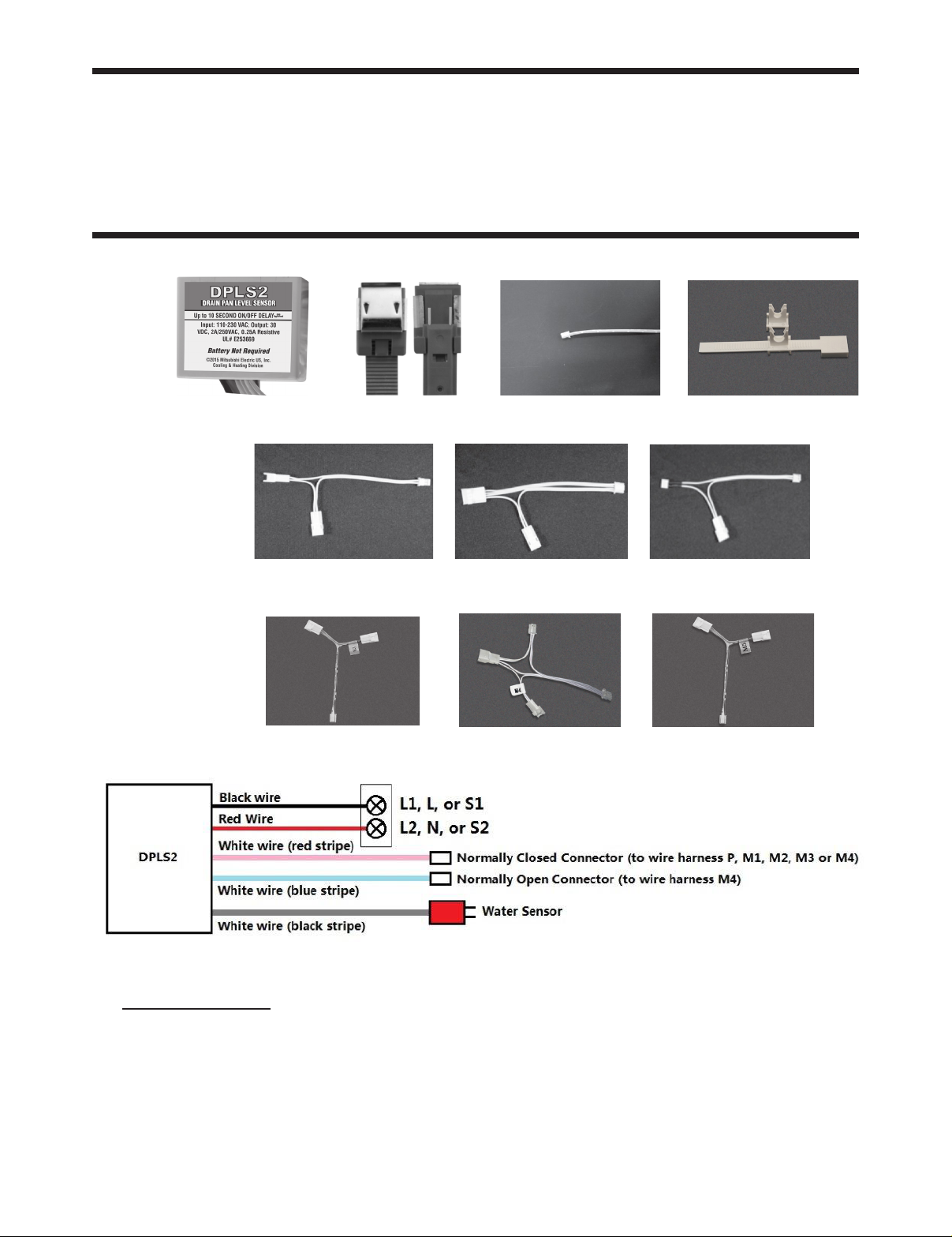
1. Components
CONTROL BOX MICRO SENSOR SPLICE CONNECTOR Coil Clips
P WIRE HARNESS M1 WIRE HARNESS M2 WIRE HARNESS
M3 M4 M5
BASE DIAGRAM FOR HIGH VOLTAGE WIRING
Work Safe, READ THIS!
ATTENTION:
FAILURE TO READ AND COMPLY WITH ALL WARNINGS, CAUTIONS AND INSTRUCTIONS PRIOR TO
STARTING INSTALLATION MAY CAUSE PERSONAL INJURY AND/OR PROPERTY DAMAGE AND
VOID WARRANTY.
This device must be installed in accordance with Equipment Manufacturer’s instructions and in
accordance with all applicable local codes,including plumbing, drainage and electrical.
“Branch circuit protection shall be provided using a Listed branch circuit protection device rated minimum
250V AC/100V DC, maximum 1A as appropriate for the supply source”
2
© 2016 Mitsubishi Electric US, Inc.
Page 3

Table 1: Description of Wire Harnesses
Type
of Wire
Harness
M2 Wire
Harness
M5 Wire
Harness
P Wire
Harness
Indoor Unit
Models
MS
MSZ/Y-A/FE/GA/GE
MSZ/Y-GL06/09/12/15/24
*Not MSZ/Y-GL18*
MFZ
Connector to
Indoor Unit
Control Board
2 pin, female
connector
(with black heat shrink)
to CN111
Connector to Thermistor
2 pin, male connector to:
RT11 (Room Temp. Thermistor)
2 pin, female
MVZ
connector (with black
heat shrink) to CN20
MSZ/Y-GL18 Connector TH - Coil Thernmistor
PKA
PCA
PEA(D)
SEZ
2 pin, female
connector to CN20
2 pin, male connector to:
TH1 (Room Temp. Thermistor)
PVA
2 pin, male connector to:
PKFY-P**NBMU-E
PLFY-P**NCMU-E
PMFY-P**NBMU-E
PVFY-P**NAMU
PEFY-P**NMHU-E
2 pin, female
connector to CN20,
CN21 or
CN29
TH1 (Room Temp. Thermistor) or
TH22 (Pipe Temp. Thermistor /Liquid)
or
TH23 (Pipe Temp. Thermistor /Gas)
Connector to
Control Board
2 pin, male
connector
2 pin, male
connector
M1 Wire
Harness
M3 Wire
Harness
M4 Wire
Harness
PKA PCA PEA(D) SEZ
PKFY-P**NH/KMU-E
PLFY-P**NBMU-E
PCFY-P**NKMU-E
PEFY-P**NMS/AU-E
MS
MSZ/Y
MFZ
MSZ-F
Indoor Unit with CN4F Port
4 pin, female
connector to CN44
4 pin, female
connector to CN112
4 pin, female
connector to CN113
3 pin, female
connector to CN111
4 pin, female
connector to CN4F
4 pin, male connector to:
TH2 (Pipe Temp.
Thermistor/Liquid) and
TH5 (Pipe Temp. Thermistor/Gas)
4 pin, male connector to:
RT12 (Coil Temp. Thermistor)
4 pin, male connector to;
RT12 (Coil Temp. Thermistor – Main)
and
RT13 (Coil Temp. Thermistor – Sub)
4 pin, male connector to:
RT15 (Coil Temp. Thermistor)
3 pin, male connector to:
Thermistor
N/A
2 pin, male
connector
2 pin, male
connector
2 pin, male
connector
© 2016 Mitsubishi Electric US, Inc.
3
Page 4

2. Installation of DPLS2
Drain Pan Level Sensor/Control:
(To ensure proper performance of product, instructions must be followed.)
1.
Disconnect (and lock-out, if required) all power to the M-Series, P-Series, S-Series or CITY MULTI
Indoor Unit at the Disconnect Switch (if installed) or at the main disconnect panel serving the indoor
and/or outdoor unit.
2.
Connect DPLS2 Splice Connector to the selected mating Wire Harness Connector – see wiring harness
selection
(Table 1). Connect the Control Box’s Splice Connector to the mating connector on the Wire Harness (Fig 1).
\
Fig 1 Fig 2: Typical indoor unit with cover removed
Typical Installation - example: Wall Mount Indoor Unit – MS/MSY/MSZ/PKA/PKFY:
1.
Remove front cover of indoor unit in order to expose the coil and the control circuit area of the unit (Fig 2).
The disassemblyof the front cover, air lters, and possibly electrical shields will vary according to style of
indoor unit installed. See the Mitsubishi Electric’s Technical Manual for detailed disassembly and details.
2.
Locate the corresponding connector (see Table 1) on the printed control circuit board and, remove the connector of the thermistor (Fig 4). Plug female connector of the Wire Harness into the printed circuit board,
and plug the male
connector on the opposite end into the thermistor connector (Fig 5).
Fig 3 Fig 4 Fig 5 Fig 6
3.
Connect black/red power input wire to indoor unit power supply terminal (S1, S2).
4.
Determine the best location for the DPLS2 Control Box (above the drain pan and outside of the main
airow):
Using the double-sided adhesive pad, mount the Control Box in a location inside the indoor unit that will
allow clearance for the cover to be reassembled (Fig 6).
5.
Reassemble all covers that were removed during the installation.
6.
Test the DPLS2:
Reconnect power to the indoor unit. Use extreme caution, beware of high voltage on the indoor unit
during testing. Turn unit on and set cooling thermostat to lowest temperature setting. Make sure to
restore power to the outdoor unit before performing the test in step 7.
4
© 2016 Mitsubishi Electric US, Inc.
Page 5
Adjustment
Adjustment
Fig 7 Fig 8 Fig 9 Fig 10
7.
Using a clip lead or other metallic object, carefully make a connection between the two pins on the
Micro Sensor (Fig 7). Indoor unit should shut down after a 5-10 second delay.
8.
Disconnect indoor unit power before proceeding to the next step.
9.
Determine the best location for the DPLS2 Micro Sensor. Make sure that power has been disconnected.
Find the drain pan below the coil in the indoor unit. It is located directly below the aluminum ns of the coil
and is slightly wider than the coil depending on the style of indoor unit.
10.
Wipe all water, dirt and dust from the drain pan with a damp cloth. Temporarily locate the Micro Sensor in the
drain pan.
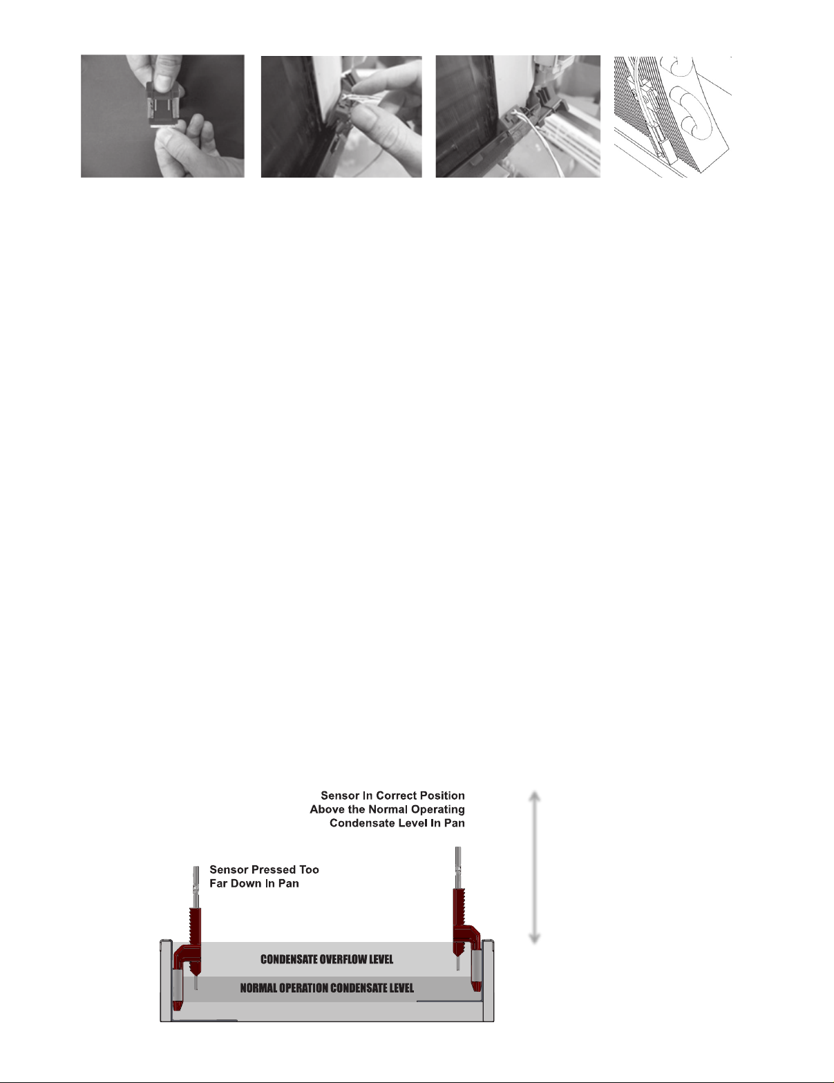
11.
Slide pan clip with sensor onto the front edge of the drain pan (Fig 8). Push the sensor down into the pan
to a position where the two sensing tips remain above the condensate level in normal operation, ensure the
Micro Sensor touches the bottom of the trough and the panel clips are pushed all the way down on the front
edge of the trough (Fig 9).
(These installation instructions are typical for all wall mounted, oor standing, ceiling recessed, and ceiling
concealed, and ceiling suspended units. Location of the micro sensor should at the drain pan no less than
3/8” from the bottom.)
12.
If there is no place for pan clip attach the sensor to the coil clip (there are two optional coil clips: 7mm and
5mm).
Clip the coil clip onto the evaporator coil. Insert the coil clip between tins or at the coil U-bend. Position the
wires up and senor pins down. Adjust sensor height by moving the vertical member (with sensor attached)
up and down. Sensor pins should be coated above normal condensate level, while below the condensate
overow level. (Fig 10)
13.
Temporarily reassemble the front cover of the indoor unit to make sure that it reattaches properly. If there
is interference with the front cover, relocate the Micro Sensor on the drain pan and recheck clearances.
14.
Once the best location has been determined, remove the double-sided tape on the Micro Sensor and reinstall it
in the same manner as described above. Ensure the Micro Sensor does not touch the bottom of the drain pan
and the panel clips are pushed all the way down on the front edge of the trough (Fig 9).
15.
Bundle and tie wrap excess wire. Locate and anchor the excess wire bundles so that they do not
interfere with the reassembly of the cover of the Indoor Unit.
16.
Reassemble the Indoor Unit cover.
17.
Turn power on to Indoor Unit and Outdoor Unit.
Adjustment
© 2016 Mitsubishi Electric US, Inc.
5
Page 6

3. Limited Warranty
1. ONE YEAR DRAIN PAN LEVEL SENSOR/CONTROL WARRANTY - MITSUBISHI ELECTRIC US, INC. (“MEUS”) warrants
to the original end-user of this Drain Pan Level Sensor/Control that, should it prove defective due to improper workmanship
and/or material under normal use and proper installation for a period of one year from the date of installation, we will
repair or replace, at our option, any defective Drain Pan Level Sensor/Control or component without charge for the part.
Replacement Drain Pan Level Sensor/Controls is warranted for the remainder of the original warranty period.
2. THIS WARRANTY DOES NOT INCLUDE LABOR or other costs incurred for servicing, repairing, removing, installing,
shipping or handling of defective or replacement Drain Pan Level Sensor/Control.
3. TO OBTAIN WARRANTY SERVICE, please contact your dealer or contractor who installed this product. If your dealer or
contractor needs assistance, its distributor is available for consultation. Should you not receive satisfactory warranty service,
please call, fax or write to us at:
warranty@hvac.mea.com
Mitsubishi Electric US, Inc.
Attn.: Customer Service,
1340 Satellite Boulevard, Suwanee GA 30024
Telephone:1-800-433-4822
4. This limited warranty applies only while the Drain Pan Level Sensor/Control remains at the site of the original installation.
This limited warranty applies only if the Drain Pan Level Sensor/Control is installed and operated in accordance with the
manufacturer’s instructions and in compliance with applicable local installation and building codes and good trade practices.
5. Any defective Drain Pan Level Sensor/Control to be replaced must be made available to your dealer or contractor in
exchange for the replacement part. You must present proof of the original date of installation of the product in order to
establish the effective date of the warranty.
6. THIS WARRANTY DOES NOT COVER any damage resulting or arising from: (a) installation that is not strictly according
to the manufacturer’s instructions; (b) incorrect mounting or locating control or sensor; (c) accident, abuse, negligence, or
misuse;
(d) improper wiring; (e) modication or alteration; (f) improper application of the product; (g) failure to properly maintain and
service
the product according to manufacturer’s instructions; (h) installation or operating of the product in a manner contrary to the
instructions
of the manufacturer; or (i) lightning, uctuations in electrical power or acts of God. This limited warranty also excludes all
costs of installation, disconnection or dismantling the product and owner-required maintenance. Consult the instructions
enclosed with the product for information regarding recommended maintenance.
7. No one is authorized to change this LIMITED WARRANTY in any respect, or to create for us any other obligation or liability
in connection with this product.
8. YOUR ONLY REMEDIES ARE PROVIDED IN THIS LIMITED WARRANTY. ANY EXPRESS WARRANTY NOT PROVIDED
HEREIN, AND ANY REMEDY WHICH, BUT FOR THIS PROVISION, MIGHT ARISE BY IMPLICATION OR OPERATION
OF LAW, IS HEREBY EXCLUDED AND DISCLAIMED. THE IMPLIED WARRANTIES OF MERCHANTABILITY AND OF
FITNESS FOR ANY PARTICULAR PURPOSE ARE EXPRESSLY LIMITED TO TERM OF ONE YEAR FROM THE DATE
OF ORIGINAL INSTALLATION. UNDER NO CIRCUMSTANCES SHALL MEUS BE LIABLE TO THE OWNER OR ANY
OTHER PERSON FOR ANY INCIDENTAL, SPECIAL OR CONSEQUENTIAL DAMAGES IN CONNECTION WITH THIS
PRODUCT, WHETHER ARISING OUT OF BREACH OF WARRANTY, BREACH OF CONTRACT OR OTHERWISE.
9. Some states do not allow limitations on how long an implied warranty lasts or do not allow the exclusion or limitation of
incidental, special or consequential damages, so the above limitations or exclusions may not apply to you.
10. This warranty gives your specic legal rights, and you may also have other rights, which vary, from state to state.
11. This warranty is valid only in the U.S.A. and is not transferable.
6
© 2016 Mitsubishi Electric US, Inc.
Page 7

Memo
© 2016 Mitsubishi Electric US, Inc.
7
Page 8

This product is designed and intended for use in the
residential, light-commercial and commercial environment.
Please be sure to put the contact address/telephone number on
this manual before handing it to the customer.
Manufactured for MITSUBISHI ELECTRIC US, INC.
DPLS2 Installation Instructions, February 2016
© 2016 Mitsubishi Electric US, Inc.
www.mitsubishielectric-usa.com
Toll Free: 800-433-4822
 Loading...