

Page 1
INSTRUCTIONS.,
'•'vlv>;Sv
FOR
>
y-ii:/-'/
'f/9^
/>.
.
i.
\ •:.
MITSUBISHI
INDUSTRIAL
SEWING
MACHINE
TWO
LOCKSTITCH
SPLIT
•
rmMiTSUBiSHi
WEEDLE
NEEDLE
MODEL
HIGH
NEEDLE
BAR
: ON-275
MACHINE
: DN-275-20
ADVANCEDANDr.VERADVANCING
ELECTRIC
SPEED
FEED
Page 2
Thank
you
for
your
purchaseof"Mitsubishi"
DN-275. Kindly read
DN-275
tion
case of
machine.
for
manual
your
your
with
ready
you
troubles
this
Instruction
reference.
for
your
caused during
INDEX
And
ready
Manual
keep
this
information
operation
machine
for
instruc
in
of
Specifications
1. Specifications 2
2.
Name
and
numberofthe
accessories 2
3. Name of main
Preparation
of
parts)
1.
Place
2.
for
Howtomount
3. Howtomount
4.
Howtoconnect
foot
pedal
5.
Howtomount
parts
for
operation
installationofmachine
the
the
the
the
(installation
machine
motor
motor
bobbin
assembly 4
6.
Howtomount
the
accessories
table 5
Head
holder,
knee
lifter
Pedal
system
presser
bar
assembly
lifter
assembly 5
Oil
pan.
Vibration
preventing
rubber
3.
Lubrication
before
startingtosew
1. Oiltobe used 8
2. Oilingto oil reservoir g
3. Oiling to main parts 3
4.
Howtoadjust
5.
Adjustmentoflubrication
hook
6. Precaution before
Howtooperate
1. How to select
2. Howtoattach
3.
Howtothread
the
lubrication...9
operation
the
machine
the
th read 1q
the
needle
the
upper
thread
4.
Howtowind
on
the
bobbin
the
lower
thread
head
lever
winder
on
for
. . .9
.4
and
10
10
11
5.
Howtoadjust
assembly
the
bobbin
winder
11
6. How to place the bobbin into the
rotating
7.
hook
2
Howtolead
8. Sewing
9.
Stoppingofthe
the
lower
start
and over 13
needle
thread..-12
bars
11
(left
and right) 14
10.
Angleofthe
stitch
11.
4
4
Adjustmentofstitch
reverse
5.
Stitch
adjustment
1.
Adjustmentoflower
tension
2.
Adjustmentofupper
tension
3.
Adjustmentofthe
length
stitching
corner
and
stitching
length
Proper
thread
thread
height
and
14
and
15
timing
15
ig
of feed
dog and pressure of presser foot -i 7
4.
Howtoremove
-7
9
5.
6.
7.
8.
9.
10.
rotating
Proper
hook
and
Up-down
needle
Proper
hook
and
Proper
hook
and
Proper
Proper
timing
timing
timing
positionoffeed
and
and
needle
between
between
take-up
between
case
between
place
hook
needle
adjustmentofthe
thread
bobbin
timing
the
the
rotating
the
rotating
lever..20
the
rotating
opener...
regulator
the
needle
18
19
20
20
21
and feed dog 22
6.
Maintenance,
Trouble
and
Repairing
1. Maintenance 23
2.
Oiling
3.
Howtofind
the
trouble
and
23
how
to repair 24
Page 3
1.
Specifications
Application:
Speed
Needle
bar
Thread
Hook:
Presser
Available
Feeding
Stitch
Needles:
Reverse
Stitch
Lubrication:
Table:
Motor:
2.
Name
Needle
Bobbin
Screw driver (large, middle,
small)
Vibration
ubber
stroke:
take-up:
far
stroke:
needle
system:
length:
stitching:
length
and
Numberofthe
(DP x 17)
Preventing
gauge:
adjustment:
....
each
Nail 9
8 pcs.
4
1 pc.
4
pcs.
pcs.
1.
Specifications
Corner
Max.
32mm
Slide
stitchingofthe
3500
spm
type
thread
raincoat
(DN-275),
take-up
Max.
and
3000
jeans
spm
(DN-275-20)
Horizontal rotating hook, fully a utomatic lubrication type
7
mm
1/4"
Double
0 ~
DPx17(135
Reverse
Push
Semi-automatic
"DN"
"Mitsubishi"
accessories
Hinged)(2)
Screw
Tweezer
Hexagon
Roller
Bobbin
Vinyl
(standard),
eccentric
5mm
button
type
set
cover
(DN-275).
lever
system
table
wernch
winder
1/8",
mechanism
X 17)
type
lubrication
Clutch
assembly
3/16",
0 ~
7mm
system
motor,
400W (1/2 HP)
each
2pcs.
each4pcs.
1
1 pc.
1
. 1
1 pc.
3/8",
(DN-275-20)
Knee
Oil
pc.
Oil
Oil
set
Cotton
set
Oiler
1/2"
lifter
pan
can
bottle
stand
assembly..1set
1 pc.
1
pc.
1 pg.
1
set
1
pc.
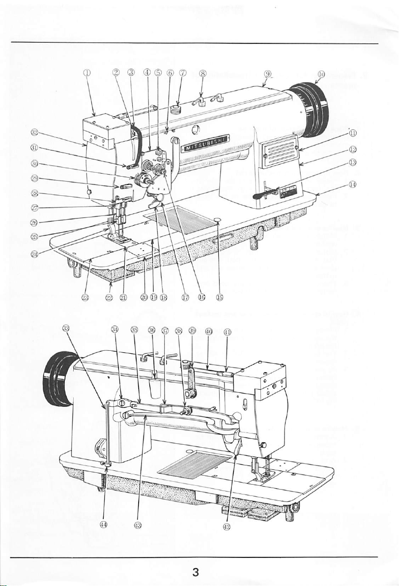
3.
Nameofthe
Top
1.
2.
Thread
Thread
3.
Thread
4.
5.
Upper thread guide (set)
Thread
6.
7.
Oil
Thread guide
8.
9.
Top
Balance
10.
Front
11.
Arm
12.
13.
Reverse
14.
Bed
15.
Stitch
button
cover
take-up
take-up
tension
guide
plunger
cover
cover
regulator
main
wheel
stitch
parts
guard
regulator
(top
lever
push
of arm)
Thread
16.
17.
18.
19.
20.
21.
22.
23.
24.
25.
26.
27.
28.
29.
30.
31.
regulator
Stop
lever
Push
lever
Slide
plate
Slide
plate
Neelde
plate
Hook
s^dle
Slide
plate
Presser
foot
Needle
clamp
Neelde
bar
Needle
bar
Thread guide (lower)
Thread guide (middle)
Thread
controller
Thread guide (upper)
(right)
(center)
(left)
holder
nut
Face
32.
33.
34.
35.
36.
37.
38.
39.
40.
41.
42.
43.
44.
set
plate
Knee
lifter
Knee
iifter
Knee
lifter
Presser
bar
screw
Knee
lifter
Knee
lifter
Connecting
Connecting
Connecting
Presser
bar
Presser
bar
Collar
bar
lever
(2)
lever
(1)
adjustoble
spring
lever
bolt
link
plate
stud
lifter
plate
spring
Page 4
Page 5
2. Preparation for operation (Installation of
machine)
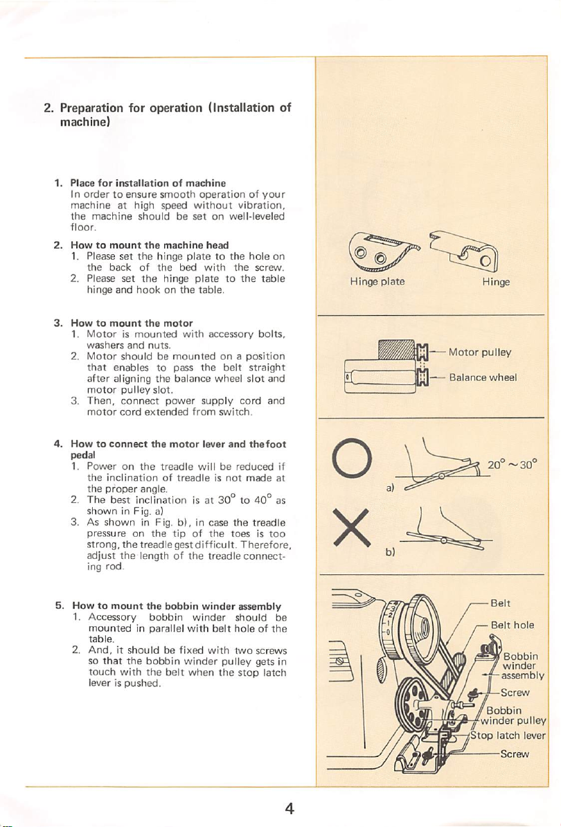
1.
Place
for
In
ordertoensure
machineathigh
the
machine
floor.
2.
Howtomount
1. Please
the
2. Please
hinge
3.
Howtomount
1,
Motorismounted
washers
2,
Motor
that
after
motor
3,
Then,
motor
4.
Howtoconnect
pedal
1.
Power
the
inclination
the
proper
2.
The
shown
3. As
shown
pressure
strong,
adjust
ing
rod.
installation
set
back
set
and
and
shouldbemountedona
enables
aligning
pulley
connect
cord
on
best
in Fig. a)
the
the
of
smooth
speed
should
the
machine
the
hinge
of
the
the
hinge
hookonthe
the
motor
nuts.
to
the
slot.
power
extended
the
motor
the
treadle
of
angle.
inclination
in Fig.
on
the
tipofthe
treadle
length of
machine
operationofyour
without
be
setonwell-leveled
head
platetothe
bed
with
platetothe
table.
with
accessory
pass
the
balance
treadleisnot
belt
wheel
supply
from
switch.
lever
willbereduced
is at
30to40°
b).incase
gest
difficult.
the
treadle
vibration,
hole
the
screw.
table
bolts,
position
straight
slot
cord
and
thefoot
made
the
treadle
toesistoo
Therefore,
connect
on
and
and
if
at
as
Hinge
plate
Motor
Balance
pulley
wheel
20°~30°
5.
Howtomount
1.
Accessory
mountedInparallel
table.
2.
And,itshouldbefixed
so
that
touch
with
leverispushed.
the
the
bobbin
bobbin
bobbin
the
belt
winder
winder
with
winder
when
belt
with
the
assembly
should
holeofthe
two
pulley
stop
screws
gets
latch
be
in
Stop
Belt
Bobbin
winder
latch
hole
Bobbin
winder
assembly
pulley
lever
Screw
Page 6
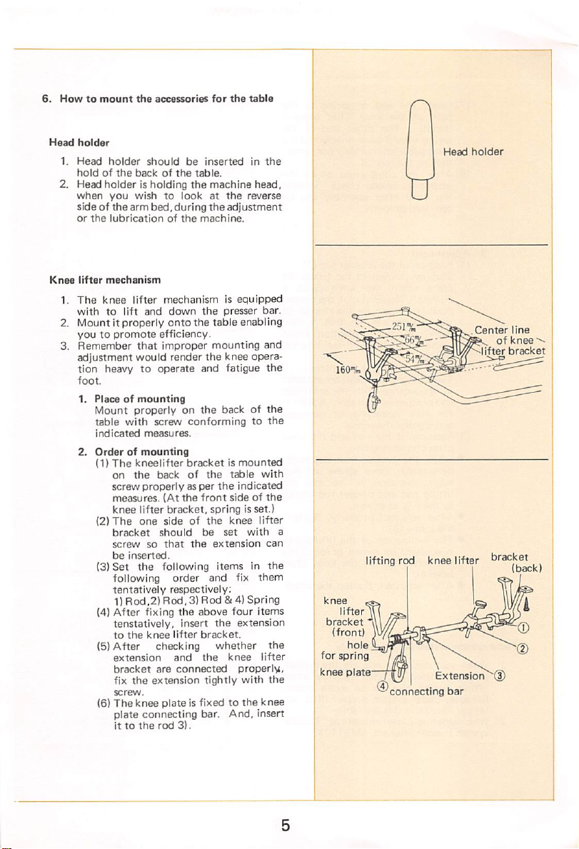
6.
Howtomount
Head
holder
1.
Head
holder
holdofthe
2. Head
Knee
1.
2. Mount it properly
holder
when
you
sideofthe
or
the
lubrication
lifter
mechanism
The
knee
withtolift
youtopromote
Remember
3.
adjustment
tion
heavy to
foot.
1.
Placeofmounting
Mount
table
indicated
2.
Orderofmounting
(1)
The
on
screw
measures.
knee
(2)
The
bracket
screw
be
(3)
Set
following
tentatively
1)
(4)
After
tenstatively.
to
(5)
After
extension
bracket
fix
screw.
(6)
The
plate connecting bar. And, insert
ittothe
the
accessories
should
be
backofthe
is holding
wishtolookatthe
arm
bed,
lifter
and
inserted
table.
the
during
the
of
the
machine.
mechanismisequipped
down
the
onto
the
efficiency.
that
improper
would
render
operate
the
and
properlyonthe
with
screw
conformingtothe
measures.
kneelifter
the
properlyasper
lifter
one
inserted.
the
Rod,2)
the
the
knee
bracketismounted
back
of
the
(At
the
front
bracket,
sideofthe
should
so
fixing
knee
checking
are
extension
that
the
following
order
respectively;
Rod,3)
the
above
Insert
lifter
bracket.
and
connected
be
and
Rod &4) Spring
the
tightly
plateisfixedtothe
rod
3).
for
the
table
in
machine
mounting
adjustment
presser
table
knee
head,
reverse
bar.
enabling
opera
fatigue
backofthe
table
indicated
sideofthe
knee
set
with
fix
four
extension
knee
properly,
with
with
lifter
them
items
lifter
the
spring is set.)
extension
itemsinthe
the
whether
knee
the
and
the
can
the
the
Head
holder
U
Center
line
of
knee
bracket
a
lifting
knee
lifter
bracket
(front)
hole
for
spring
knee plate—j
®
rod
knee
connecting
Extension
bar
lifter
bracket
(back)
Page 7
(7)
spring
(8)
After
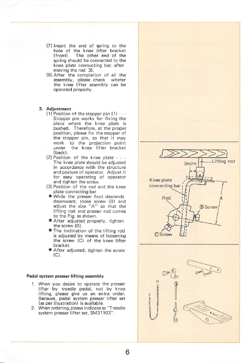
3.
Adjustment
(1)
Stopper
place
pushed.
position,
the
work
under
(2)
Positionofthe
The
in
and
for
and
(3)
Positionofthe
plate
•
While
downward,
adjust
to
•
After
the
•
The
the
bracket.
•
After
Insert
the
hole
(front).
knee
moving
assembly,
the
operated
Positionofthe
(back).
accordance
lifting
the
is
adjustedbymeansofloosening
(C).
endofspringtothe
of
the
knee
The
shouldbeconnectedtothe
plate
connucting
the
the
completionofall
please
knee
lifter
properly.
pin
where
Therefore,atthe
please
stopper
to
the
the
knee
plate
postureofoperator.
easy
operating
tighten
connecting
the
presser
the
size
rod
and
Fig, as
adjusted
screw
(B).
inclination of
screw
(C)ofthe
adjusted,
lifter
other
endofthe
bar,
rod
3).
check
assembly
stopper
works
the
pin,sothatitmay
knee
the
loose
shown.
pin (1) —
for
fixing
knee
fix
the
stopper
projection
lifter
knee
plate
shouldbeadjusted
with
the
structure
Adjust
of
screw.
rod
and
the
bar
foot
descends
screw
"A"sothat
presser
rod
properly,
the
lifting rod
knee
tighten
the
bracket
wheter
can
plate
bracket
operator
(B)
tighten
after
the
the
proper
point
- - •
knee
and
the
comes
lifter
screw
be
is
of
3m/ml-^
it
Knee
plate
connecting
bar
Lifting
rod
©Screw
Pedal
1.
2.
system
presser
When
you
lifter
lifting,
Because,
(as
When
system
desiretooperate
by
treadle
please
pedal
per
illustration)isavailable.
ordering,please
presser
lifting
assembly
pedal,
give us an
system
presser
indicateas"Treadle
lifter
set,
SM31103".
not
the
extra
presser
by
lifter
knee
order.
set
Page 8
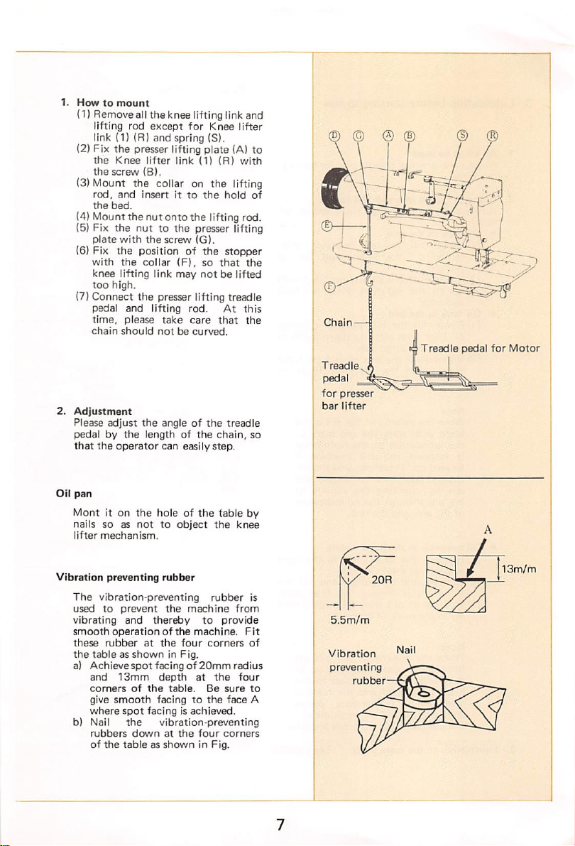
1.
Howtomount
(1) Removeall the knee lifting link and
lifting
rod
except
for
link (1) (R) and spring (S).
(2) Fix the presser lifting plate (A) to
the
Knee
screw
and
bed.
the
with
the
lifting link
high.
and
please
should
adjust
operator
it on
lifter
(B).
insertitto
nuttothe
the
screw
collar
the
presser lifting treadle
lifting
take
notbecurved.
the
angleofthe
lengthofthe
can
the
holeofthe
nottoobject
the
(3)Mount the collar on the lifting
rod,
the
(4) Mountthe nut onto the lifting rod.
(5) Fix
plate
(6) Fix the position of the stopper
with
knee
too
(7) Connect
pedal
time,
chain
2.
Adjustment
Please
pedalbythe
that
the
Oil
pan
Mont
nails
so as
lifter
mechanism.
Knee
link
(11
the
presser lifting
(Gl.
(F),sothat
may
not
rod.
care
easilystep.
(R)
hold
be lifted
At
that
treadle
chain,
fable
the
lifter
with
the
this
the
by
knee
of
Cham—
Treadle
pedal
for
Motor
Treadle
pedal
for
presser
bar
lifter
so
Vibration
preventing
The
vibration-preventing
usedtoprevent
vibrating
smooth
operatlonofthe
these
rubber
the
tableasshowninFig.
a)
Achievespot
and
corners
give
smooth
where
b) Nail
rubbers
of
the
rubber
the
thereby
the
machine
machine.
four
to
corners
and
at
facingof20mm
13mm
depth
of
the
spot
facingisachieved.
the
downatthe
tableasshowninFig.
at
table.
facingtothe
vibration-preventing
Be
four
rubber
provide
the
sure
face
corners
is
from
Fit
of
radius
four
to
A
V/
5.5m/m
Vibration
preventing
rubber
20R
13m/m
Page 9
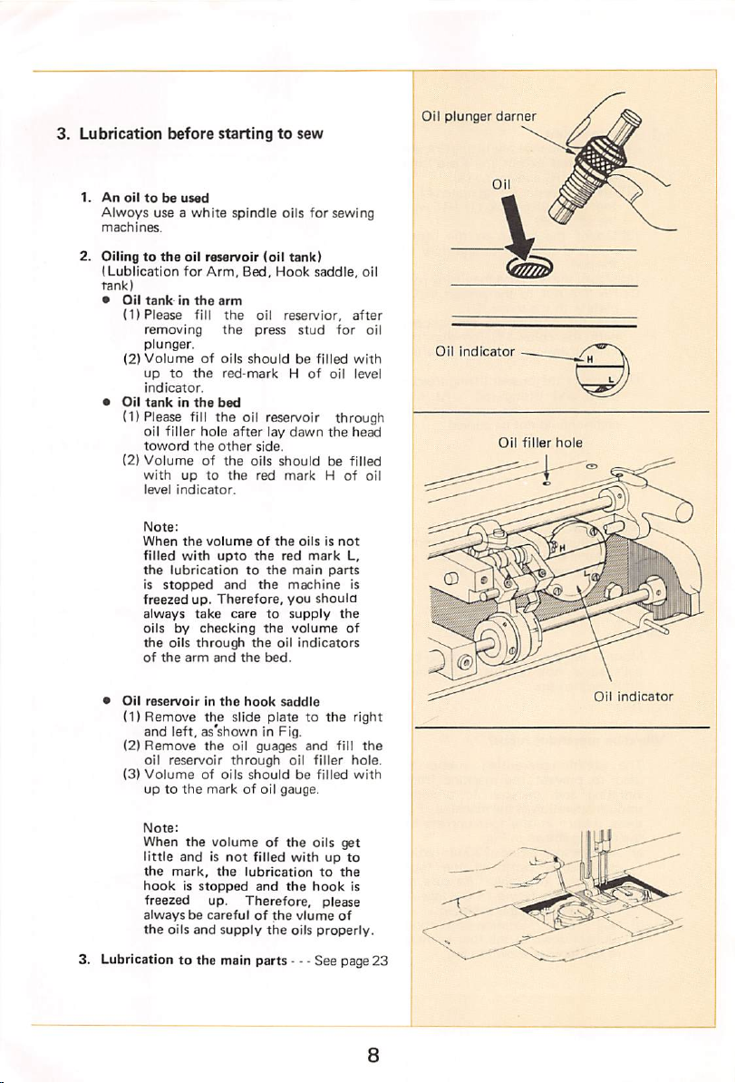
3.
Lubrication
before
startingtosew
Oil
plunger
darner
1.Anoiltobe
Alwoys
use a
machines.
2.
Oilingtothe
ILublication
tank)
*
Oil
tankinthe
(1)
Please
removing
plunger.
(2)
Volumeofoils
uptothe
indicator.
•
Oil
tankinthe
(1) Please fill
oil
toword
(2)
Volumeofthe
with
level
Note:
When
filled
the
is
freezed
always
oilsbychecking
the
of
•
Oil
reservoirinthe
(1)
Remove
and left, as'shown in Fig.
(2)
Remove
oil
(3)
Volumeofoils
uptothe
used
white
spindle
oil
reservoir
for
Arm,
Bed,
arm
fill
the
the
shouldbefilled
red-markHof
bed
the
filler
uptothe
indicator.
the
with
lubricationtothe
stopped
oils
the
arm
reservoir
oil reservoir
hole
after
the
other
volumeofthe
upto
and
up.
Therefore,
take
caretosupply
through
and
the
hook
the
slide
the
oil guages
through
markofoil
oils
the
shouldbefilled
oils
for sewing
(oil
tank)
Hook
saddle,
oil
resen/ior,
press
stud
lay
dawn
side.
shouldbefilled
red
markHof
oilsisnot
the
red
mark
main
the
machine
you
shoula
the
volume
oil
indicators
bed.
saddle
piatetothe
and
oil
filler
gauge.
oil
after
for
with
oil level
through
the
head
L,
parts
is
the
of
right
fill
the
hole.
with
oil
Oil
indicator
Oil
filler
hole
oil
Oil
indicator
Note:
When
the
andisnot
mark,
oils
and
volumeofthe
the
supply
little
the
hookisstopped
freezed up.
alwaysbecarefulofthe
the
3. Lubricationtothe main
oils
filled
lubricationtothe
and
the
Therefore,
the
parts
get
withupto
hook
please
vlume
of
oils
properly.
- - - See page 23
is
8
Page 10

4.
Howtoadjust
1.
Oil
plunger
When
startingtooperate
please
push
oil
penetrates
necessary
2.
When
the
please
push
that
the
back
and
Note:
Keep
putting
(a rest)
shown
cose of
outofoperotion.
be
careful
5.
Adjustmentofhook
(1) Lay
down
other
(2)
(3) A red line mark is
(4)
side.
Loosen
the
saddle.
ing screw,
volumeoflubrication.
screw
clockwise
markisto
turn
counterclockwise
After
adjusted,
the
lubrication
device
the
the
press
bar
partsinthe
stop
throughly
machineisoutofoperation,
the
press
oils
arm.
press
stud
bar
put
to lubricate
the
press
in Fig. by all
happentoflow
machine,
downsothat
into
downward
automatically
automatically.
bar
back
means
Otheriwse,
out.
lubrication
the
machine
nutonthe
which
increase,
tighten
head
toward
sideofthe
indicatedinthe
shows
the
Turn
the
the
istoreduce.
the
nut.
adjust^le
basing
andonthe
adjust
standard
red
contrary,
as
in
hook
the
the
line
Press
bar
for
oil
plung
an
When
operate
so
Press
bar
for
oil
plunger
Oil
plunger
knob
When
not
operate
6.
Precaution
When
timeorwhen
long
(1) It is
necessary
(2)
Fill
each
(3)
Please
downward.
(4)
Operate
penetrated
before
the
machineisoperated
interval:
operating
necessarytofill
parts.
oilsatthe
oil
reservoirs.
push
the
the
machine
throughly
startingtosew
the
oils
throughly
levelofred
press
bar
for
slowly
Into
necessary
for
the
machine
markedHof
oil
plunger
until
oils are
first
after
into
parts.
Adjusting
screw
increose
0)
Special
nut
Page 11

4.
Howtooperate
1.
Selection
(1)
Always
thread.
{2) in
twistedorleft-twisted,
shown
with
2.
Howtoattacf
Use
1)
Turn
to
position.
2)
Then,
3) Hold
groove
insert
needle
4)
Then,
the
of
thread
use
left-twisted
ordertocheck
in Fig.
your
right
the
raise
the
loosen
side
it as
clamping
tighten
the
{135X17)
balance
the
needlesothat
deeply
DP X 17
machine
and
hand.
needle
needle
the
faces
the
wheel
hole.
thread
if a
thread
hold
the
twistittoward
needle.
toward
bartoits
needle
clamping
its side
each
two
as it will go
neelde
clamping
for
is right-
thread
you
with
needle,
into
upper
you
so as
highest
screw.
long
and
the
screw.
Needle
clamp
Needle
as
groove
Thread
Thread
take-up
groove
side
Thread
guide
clamping
guide
y.
screw
side
Q
3.
Howtothread
The
following:
1)
Turn
that
upto
2)
Thread
side
respectively:
1.
2.
3.
4.
5.
6.
7.
8.
9.
10.
upper
Thread
Thread
Upper
Thread
Thread
Thread
Thread
Thread
Needle
Needle
the
its
the
spool
the
upper-thread
threadispassed
balance wheel by
thread
highest
the
take
position.
two
threads
in
guide
(top
guide
thread
regulator
guide (arm)
take-up
guide
(arm)
guide
(arm)
guide
(arm)
clamp
the
accordingtothe
your
up
leverisraised
from
following
cover)
the
hand so
left
order
10
Thread
guide
Page 12

4.
Howtowind
(1)1
nsert
shaft,
(2) As shown in Fig., pass
wind
times
machine.
(3) When
thread,
free
the
the
on
the
from
the
lower
bobbin
edgeofthe
the
bobbin
the
pulley
the
belt
into
bobbin,
and
is fully
will
(4) This operation can be
S.
Howtoadjust
(1) It is
evenly
(2) In case of uneven winding
If it is
screw (Al shown in Fig, and move
thread
right
thread.
the
(3)
Strengthofthe
Thereisthe
maybedamagedifthe
too
the
the
led
(4)
Best
woundupto
thread.
poor
the
bobbin,
to
andtothe
the
with
bobbin
that
thread,
the
desirable
inclinedtoleftorright.loosen
guide
rest
so astoobtain
After
screw
tightly
pressureofthe
nut
(B), so
slightly
resultisobtained
Excessive
draw-outofthe
amount
turn
the
left
adjusting,
(A).
winding
possiblity
with
that
outofthe
4/5
of
the
when
right
when
slightlytothe
thread.
the
of its full
winding
thread
screw
the
threadonthe
the
the
thread
and
automatically
stopped.
done
winder
bobbiniswound
uniform
that
bobbiniswound
regulator
thread
regulator
when
thread.
wound
(C)
windingisexcessive,
insufficient.
bobbin
bobbin
winder
thread and
about
5 to 6
operate
wound
while sewing.
assembly
left
winding
please
tighten
the
bobbin
Please
adjust
plate
can be pul
plate,
the
bobbin
capacity
will
result-in
To
adjust
on
shown
in Fig.
with
with
with
the
the
the
the
be
Bobbin
case
thread
guide
To
adjust
the
the
or
of
is
thread
windingofthe
guide
to,
leftorright.
threadbymoving
6.
Howtoplace
hook
(1)Turn
(2)
(3)
(4)
tfie
the
that
the
the
the
the
flap
balance
the
needle
position.
slide
hookasshown
bobbin
hook
down
so
highest
Open
(A) of
Hold
threadbyabout
into
Then
bobbin
plate
5cm,
center
the
wheel
pulling
into
the
rotating
with
pull up
in Fig.
out
fit
your
the
the
barisraised
and
and
pin.
latch lever(A},
upto
the
end
bobbin
hand,
latch
Thread
its
of
Slide
hook
plate(g)
center
slide
plate
®
hook
center
11
Page 13

7.
Howtolead
(1) Lead
(2)
the
the
hook
After
hook
(2)
and
ontothe
the
lower
thread
(1)
opener
thread
(1)
shown
through
(3),pull
endofthreadtothe
center
led
the
center
the
bed.
from
in Fig.
the
the
the
groove
groove
hook
thread
beak
out
Thread
of
of
Thread
Bobbin
case
opener
(3) Holding
left
hand
slowlybyright
thread
shown
of
the
(Then,
the
lower
hook.)
(4)Atthis
toward
as
shown
(5) Pull
the
the
directionasshown
(6)
Please
opened
the
end of
the
turn
hand.
the
through
regulating
bobbin
the
upper
Then
lower
the
and
are
led
out
in Fig.)
feed
dog.
the
thread accerdingly lead to
thread
time,
the
the
counterclockwise
in Fig.
lower
thread
and
close
when
the
the
slide
bobbin
in Fig.
plate
was
thread by
balance
wheel
the
upper
thread
needle
hold
springofthe
should
turn
direction
leadittoward
which
was
inserted.
(as
12
Page 14

8.
Sawing
start
and
ouer
Howtooperate
*
Sewing
(1) Lift the presser foot and
cloth
(2)
Turn
your
Note:
When
upper
in
lengthsoas
*
Sewing
(1) When sewing over,
shouldbeliftatits
(2) Lift
cloth
(3)
Trim
the
machine
start
to
start
and
pulled
presser
diagonally
sewing
needle
nottobe
foot
upper
the balance wheel
hand
startingtosew,
thread
over
the
toward
bothofthe
put
under
toward
stitches
please
outbyapprox.
foil
out.
the
thread
highest
position.
and
pull
other
side.
and
lower
the
the
your
the
leave
10cm
take-up
out
the
thread.
part
needle.
side by
cloth.
the
lever
sewn
of
13
Page 15

9.
Stopofneedle
0
Set
Note:
the
machineisworking,
operating
stop
take-up
sition.
(1)
Stoppingofthe
When
stop
Fig-
(2)
Stoppingofthe
When
stop
Fig,
(3)
Operationofthe
When
bars
please
opposit
turned
and
10.
Relationship
er
sewing
(DThe
according
showninthe
the
(2) When
the
stitches
obtained
(3)
For
stitch
stitch
diagram.
bar
(rightorleft)
the
stop
Stop
the
after
the
proper
needle
curving
example.
leverto"L"or"R"
lever
maybeoperated
the
stop
machine
lever has
stop
lever
stop
lever
resume
push
automatfcallytothe
and
decide
*fch1
length
numberissix
foratime
come
needle
the
toward
needle
the
toward
the
the
operation
the
side.
two
needle
between
stitch
corner
to
the
following
gaugeof1/4")
the
angle,
for
the
COCO
from
the
In case of
by
but
it is
lever in
about
bar
left
needle
the
mark (L) as
bar
right
needle
the
mark
two
needle
operationOftwo
pushing
Then,
operation
Curving
length
sewing
proper
stitch
the
outside
diagram.
2.9mm,
stitihesasshowninthe
desirable
the
bestoforder
when
its
heighest
(left)
bar,
(right)
bar,
(R) as
bars
with
one
lever
toward
the
stop
neutral
canbedone.
angleofthe
canbeobtained
stitch
diagram
length
according
proper
needle,
40®
curving
the
most
even
the
turn
shown
turn
shown
needle
lever
position,
length
(In
case
number
can
though
thread
the
needle
bar,
the
com
and
proper
the
po
to
be
for
in
In.
as
of
of
to
Stop
lever
is
Pushing
lever
Curving
angie
(40")
Proper
gauge
\
S.N
C./\
30®
40®
50®
60®
70®
80®
90®
100®
no®
120®
130®
140®
stitch
1/4")
2 3
5.5
3.2
2,7
2.2
1.8
1.5
1.1
length&stitch
4 5
4.8
4.4
3.5
4.6
3 4
2.8
2.3
1.9
1.6
1.3
27
2.2
1.8
1.5
1.3
3.7
3.0
2.5
2.1
1 ft
1.5
1.2
number
6
4.0
2.9
7 3
1.9
1.5
1.3
(needle
7 8
3.7
2.5
2.0
1.6
3.0
2.2
1.7
14
Page 16

11.
Adjustmentofstitch
*
Adjustmentofstitch
(1) Pushing
the
balance
(2)
Then,
the
and
the
(3)
Push
the
so
that
this
time
dialonthe
ing on
push
button
the
push
balance
push
the
set
the
push
wheel
button
button
balance
the
balance
arm
shown
length
and
length
button
slowly
goes
wheel
down
wheel
graduation
wheel
and
then
in Fig.
revers
down
toward
down
stops
additionally
rotates.
(0~5)
with
release
stitch
and
you.
further
rotating.
ofthe
the
mark
turn
At
the
Markingofthe
Balance
arm
wheel
5.
Note:
Please
push
operationofthe
*
Reverse
(1)
Reverse
reverse
Stiteh
adjustment
*
Adjustmentofthread
Thread
that
link
fabrictoprouide
A.
In
caseofFig. B,
threadIstoo
lower
In
case
threadistoo
upper
1.
Tension
(DThe
tensionisno
except
thread,
(2)
Turn
hook
sirengther
counterclockwise,
*
Thread
(1)
Thread
the
However,
machine
part
remember
button
stitch
sewing
lever
the
togetherinthe
being
tension
upper
thatdonot
by
all
machine.
canbedone
pushed
and
proper
should
and
perfectasshown
threadistoo
of Fig. C,
threadistoo
of
adjustment
the
center
adjustment
and
tight
the
tightorthe
the
lower
thread
of
need
the
special
some
adjustment
thread
tension
to
tight,
to
tension
screw
tension
screwIsslitted,sothat
can
if It
looses
operation,
tightenitaccordingly.
push
means
down.
timing
tension
be
adjusted
lower
middleofthe
the
tensionofupper
or
the
loose.
tensionofthe
loose.
the
lower
necessary
sewing
fabricorthe
willbenecessary.
screwofthe
the
clockwise
and
turn
weoken.
be
made
often
please
open
while
during
thread
tension
tension
ulrtually
to
while
the
the
the
will
sewing
In Fig,
lower
thread
Is
the
easily.
the
slitted
Push
button
;The
•is
too
so
of
lower
:The
'threadistoo
tensionofthe
is
too
Leverse
Proper
tensionofthe
loose,orthe
threadistight.
tensionofthe
loose.
ever
Stitch
uppor
tensionofthe
upper
tight,orthe
lower
thread
thread
tension
of
to
Thread
tension
screw
Loose
15
Page 17

2.
Tensionofupper
(1)
Adjustmentofthe
canbeachievedbychanging
of
the
thread
thread
tension
strength
thread
*
Pressureofthread
{1)To
nuttothe
(2)T0weaken,
and
takeupspring.
strengthen, turn
right.
thread
upper
tension
regulator,
operating
tension
turntothe
discs of
discs
the
thread
left.
thread
tension
the
pressure
the
as well as
range
of
tension
upper
the
the
iThread
•
tension
nut
,
iOk'Strong
* Strengthofthe
Adjust
ing .to
(1) In case of standard fabrics. Approx. 25g.
(21
{31
(4) How to adjust the strength of the spring
the
In case of light fabrics, weaken the spring
In case of heavy fabrics, strengthen
spring
1)
Loosen
shown
2)
Next,
of
the
the
andtothe
3)
Tighten
adjustmentisdone
* Operating range of the thread take up spr
ing
(Din
caseofstandard
Adjust
the
the
positionofthe
when
the
positionofthe
when
the
highest
{2) In
case
Decrease
case
(3) In
Increase
* Howtoadjust
(D
Loosen
the
thread
(2)To increase the operating range, turn
the
stopper
turntoleft,
(3)
After
adjustment, please tighten
screw.
thread
the
strengthofthe
materialstobe
the
screw
in Fig,
fitascrew
thread
studtothe
driver
controller
lefttosterngthen
righttoweaken
the
screw
fabric
interval by
up lever
thread
take
up
tensioned
operating
operating
the
operating range
screw
whichismounted
to
right
thread
take
and
of light fabrics
the
of heavy fabrics
the
the
controller
take
up spring
spring
sewn.
Approx.
Approx.
(A)
on
the
into
the
stud
and
it.
lA)
after
shown
8mm
approx.
take
downtothe
take
up spring
lifts
upper
up spring
thread.
comes
lever
the
range.
range
disc.
andtodecrease,
accord
20g.
the
30g.
arm
groove
turn
in Fig.
from
up
the
the
Thread
tension
stud
Thread
takeupspring
(.$
Screw
it,
its
on
weak
Thread controller disc \ Stopper
strong^,.-'^
weak
strong
Screw
16
Page 18

3.
Adjustmentoffeed
of
the
presser
The
heightofthe
pressure
properly
tobesewn.
(Din
(2) In case of heavy fabrics:
(3)
*
(1) Lay
(2)
(3)
(4)
(5)
When
feed
*
on
adjusted
case of light fabrics:
If
the
feed
the
pressure
sewn
is
willbeobtained.
If
the
feed
or
the
pressureonthe
sewnistoo
will
become
become
unevenorstitch
obtained.
The
height of feed dog is measured
the
feed
from
the
wheelbyhand.
Light
fabrics
the
needle
Standard
the
needle
Heavy
fabrics
the
needle
Adjustmentoffeed
down
other
side.
Turn
the
stop
turnning
be
raisedtoits
the
needle
Loosen
the
Adjust
the
height
moving
as
showninFig.
Tighten
adjusted
Adjustmentofpressureofpresser
Adjustment
foot
arm
a)
the
deliver
dogisadjustedat1.0mm.
can
presser
regulating
shown
Turn
then.
b)
Turn
dog
foot
feed
the
sewn
accordingtothe
dogisraised
on
too
strong,
dogisnot
weak,
poor,
dog
raisedatits
needle
plate
plate
surface
fabrics
. .
plate
surface
....
plate
surface
the
machine
balance
when
plate.
screwofthe
feed dog
the
screwofthe
heightofthe
the
machine,
of
pressureofthe
be
done
in Fig.
the
screwtothe
the
screwtothe
height
and
dog
as well as
material
excessively
the
materials
shrinked
raisedsufficienctly
materialstobe
the
feeding of material
and
stitches
skipping
highest
turning
the
Approx.
Approx.
Approx.
dog
wheel by
highest
feed
screwatthe
height
head
the
feed
position
feed
to
barupand
feed
feed
the
by
means
O.Smmfrom
1.0mm
1.2mm
toward
dog
bar.
the
dog.
heightofthe
righttostreng
lefttoweaken.
pressure
the
must
materials
to
sewing
will
may
when
position
balance
from
from
the
hand
and
would
from
desired
down,
baratthe
foot
presser
of
the
center
O.Smm
be
or
be
mmmmimmMzmTiz
mm,
LOmn
1.2mm
be
Feed
bar
Feed
bar
screw
Pressur regulating
strong
of
weak
screw
17
Page 19

4.
Howtoplace
*
Howtoplace
Place
belowInthe
entangledinthe
is
or
•
Howtoremove
11)
Turn
itwhenthe
position.
(2)
Lay
other
(3) Loosen
(small)ofthe
the
changed
when
the
down
side.
and
remove
the
and
remove
hookinthe
eventofthe
hook,
duetoshockorother
it is
replaced
the
balance
wheel by
needle
the
machine
the
three screws of
hook
the
position
when
withanew
hook
is rais^ to its
head
saddle.
hook
hand
toward
hook
described
thread
its
position
and
highest
the
gets
causes,
one.
stop
the
gear
Hook
gear (small)
Screw
Hook
saddle
(4) Raise up
move
(5)
Remove
(6)
Remove
(7)
Remove
(8)
Take
out
*
Howtoplace
(1) Place
(2)
(3)
the
howtoremove
Place
tongue
position
The
position of placing
producedinthe
the
the
slide
the
needle
the
feed
the
opener.
the
hook holding it.
the
hookinthe
the
needle
of
bobbin
slotofneedle
machine
plate.
plate.
dog.
hook
it.
plate
case
following
head as it is,
waytothe
so astofit
with
plate.
the
hook will be
ways.
contrary
the
hook
the
and
Bobbin
case
opener
Hook
positioner
TongueofBobbin
18
Page 20

5.
The
timingofthe
(1)
Please
length
dial.
(2) As shown in Fig., adjust
the hook and the
position,
2,0mm
Topofthe
lower
position
Tipofhook
the
needle
The
gap
edle
and
{3} In
ordertoadjust
hook
following
* It is
remove
feed
dog.
*
The
positionoftipofhook
As
described
soasto
needle.
(1) Lay
the
(small)
(2)
Raise
turning
stopitwhen
2.0mm
(3)
Turn
the
needle.
(4)
Adjust
saddle
screw
the
and
be
Note:
At
to
screw
leave
each
(5)
Tighteningofthe
Tighten
order:
(1) Pushing
(2)
(3)
hook
set
the
with
the
when
from
its
needle
from
between
the
tipofthe
and
needleasshown
wayisrecommendable;
easiertoadjust,ifyouatfirst
the
presser
below,
cometothe
down
the
other
side,
set
screws
the
machine
the
balance
from
the
hookbyhand
tipofhooktothe
the
by
A, B
gap
between
the
lateral
0.05mm.
this
time,
loosen
the
(C)
too
free
frome
gears
(large)
the
the
the
side
tighten
the
(C)atfirst.
Checking
needle
and
screw
(A)
Tighten
the
and
needle
amount
graduation
the
lowest
the
of
the
ne^le
at the
needleisraised
position.
hole
the
tipofthe
lateral
faceofthe
hook.0.05mm
the
positionofthe
foot,
needle
adjust
the
center
machine
then
(3 pcs.)
head
loosen
head
the
2.5ofthe
position of
following
Center
in Fig.,
plate
tipofhook
lineofthe
as it is,
wheelbyhand
the
needleisraised
the
lowest
position.
and
centerofthe
position
loosening
and
sideofthe
please
screwinthe
C (2
the
tipofthe
take
set
screw
loose,
engagement
and
screw
of
the
the
adjusting
pcs.),sothat
needle
care
of
and
not
(small).
following
gear (large) slightly to
of
the
hook
set
screwofthe
the
gap
hook,
between
tighten
the
completely.
screw (B).
stitch
1.6mm
hook.
toward
the
adjust
not
the
to
of
saddle,
screw
the
and
gear
and
and
hook
hook
.may
the
the
1.6mm
Tooofthe
needle
hole
2.0mmup^T~ri
by
of
ne
Lowest T V
position
of
the
needle
Center - ^
of
the
needle
Tipofthe
Screw
gear
Set
screw
by
A
screw
B screw C screw \
Hook
saddle
^
hook
Tipofthe
O.D5mm
A
B
screw
\
screw
hook
Hook
saddle
19
Page 21

6.
Adjustment
needle
{1i Using
box.
clamp
(2)
Remove
bar.
(3) Adjust
and
the
(4)
Insert
stopper,
(5)
After
(A)
7.
Proper
When
of it,
timing
following
(1)
Turn
it
to
(2) Lay
other
arrow (timing mark) of timing
and
holderisproperly
(3) In
not
Fig. Please adjust it by removing
timing
of
the
up-down
the
hex agon
loosen
setting.
the
the
down
needle
the
adjusting,
completely
timingofthe
removed
the
relationofhook
wouldbeadjusted
condition;
the
balance wheel by hand and
when
the
its
highest
down
side,
the
caseofthe
corresponded
belt.
wrenchinthe
the
screw
needle
clamp
clearance (C), by moving up
the
adjusting
clamp.
adjusting
and
place
tighten
with
hook
the
timing
thread
position.
the
machine
and
checkupwhether
bossofhook
corresponded.
arrow
properlyasshown
position
(A)
for
from
the
screw
screw
the
needle
the
the
hexagon
and
takeuplever
beltbyreplacing
and
takeuplever
accordingtothe
takeuplever
head
towardthe
belt
shaft
and
the
accessory
needle
needle
for
the
upto
the
clamp.
screw (B)
wrench.
stop
raised
the
pulley
bushing
boss
the
Stopper
of
Needle
bar
Needle
comeup
^
Needle
down
come
Adjusting
j
screw j
Needle
clamp
is
Mark in bed,
in
Timing
mark
Timing
belt
pulley
Timing
belt
8.
Relative
(DTurn
(2) At
(3) When
positionofthe
the
when
its
this
Fig.
the
farmost
the
opener
balance
opener
time, check up
the
gap
exceedingly,
it
to
between
shouldbeby
in
decreased
positionofthe
(B) of
hook
and
wheel by
holder
from
(A) of
hook
approx.
would
opener
holder as shown in Fig.
the
hand
and
would
the
needle
whether
and
the
0.2mmasshown
be increased
please
adjust
loosing
the
opener
stop
become
plate.
the
gap
opener
the
screw
Approx.
0.2mm
or
Opener
Opener
holder
20
Page 22

9.
Positionoffeed
(1) Pushing
buttononthe
toward
stops
stitch
the
and
lengthIszero.
the
you.
automatically
length.
balance
when
(21Atthis time, when
and
(0)ofbalance
corresponding
arm,
please
as
following:
(1) Lay
down
the
other
(2) Loosen
feed
regulator
(3) Pushing
balance
tion
(0)or(5)tothe
arm.
(4)Atthe
screws
regulator
stitch
length
bed,
turn
and
when
shows
On
wheel
the
toward
stopsitshows
the
wheel
with
the
large
cam.
push
and
the
the
machine
position,
adjust
side.
the
the
wheel
adjusted
(2 pcs.)onthe
regulator
the
balance
the
balance
the
contrary,
the
graduation (5)
would
mark
feed
regulator
head
screws
(2 pcs.)
button,
adjust
the
markonthe
tighten
cam.
other
the
turn
push
wheel
wheel
largest
turn
side,
stitch
not
on
the
cam
toward
the
gradua
the
Feed
rock
shaft
be
cam
of
Large screw
Feed
regulator
cam
21
Page 23

10.
•
Relative
positionofneedle
Adjustsothat
of
the
{1j Pushing
on
the
set
the
the
arm.
(2) Lay
down
other
(3)
Loosen
feed
shown
(4)
Raise
feed
bar
the
needle
centerofthe
(5)Atthis
machine
and
(B)ofthe
(6) As
this
whether
(right)
angle.
(7) If it Is
front
screw (C) of
then
right
(8)
After
tighten
needle
needle
holeofthe
the
stitch
bed,
graduation
side.
the
link
In Fig.
the
movingtofront
position
head,
time,asshown
the
would
not
cover
adjust
angle
adjusted
the
regulator
turn
the
(0) to
the
machine
screw
on
machine
(A)
the
back
head
would
be
needle
as it is,
and
tighten
feed
link.
rod
and
properlybeadjustedatright
at the right angle, remove
and
top
cover,
the
needle
it so astobeatthe
eack
other.
the
screws (A) (B)
respective
and
feed
dog
dropsinthe
feed
dog.
push
balance
wheel
the
mark
head
toward
and
(B)ofthe
of
the
and
adjust
and
backsothat
dropped
holesoffeed
lay
down
the
screw (Aj
in Fig.,
check
the
feed
and
loosen
bar
lifting link,
and
(C).
center
button
bed
on
dog.
proper
parts,
and
the
the
the
the
on
link
the
as
up
the
Back
of
the
Feedink(Left)
Screw
Center
\ N\ Feed shaft and pin
\\\Feed
(A)
line
of
Screw
link (right)
prin
(C)
Needle
connecting
(B)
bar
rod
22
Needle
bar
connecting
rod—f-7
Screw
f
Page 24

6. Maintenance,
trouble
1.
Cleaning
Clean
away
teethoffeed
and
thread
ununiform
2.
Lubrication
The
most
lubrication.
the
machine
and
tear.
(1)
The
numberoftimesoflubrication
1. In
3
timesIna
2. In
everday
(2)
Place
(1)Dust
lubrication
cleaned
and
on
(2) You
place
in Fig.
face
(3)To
opening
to
opening
howtofind
always
dust
dog,
thread
controller
stitching.
important
Please
the
caseofusual
the
eventofcontinuous
wheretolubricate
attached
the
the
dust.
should
where
plate).
the
the
disc
careofthe
If
you
neglect
shortened
lubricateasfollows:
week
on
os
away,
requirred
for
lubrication
oil
throughlytothe
indicatedbyarrow
(bed
and
place
(A) in
the
slide
place
(B) In Fig., oil
the
slight
and
repari
covering
the
tension
which
machine
it,
withaheavy
the
working
once
everyday
the
parts
the
dust
absoads
is
not
inside
partsonthe
Fig.,
plate
(left),
plate
(front).
hook,
regulator
will
cause
life
...
at 2 or
working
where
should
sufficient
every
shown
oil
the
wear
oil
after
and
after
is
of
be
23
Page 25

3.
Trouble
and
repairing
Trouble
1.
Stitch
skipping
Cause
1)
Duetoneedle
a)
Bent
b) Damaged needle (weak)
c)
2)
Needle
a)
b)
c)
3)
Damaged
(Proper) (Improper)
needle
Needle
and
matching
thread
not
inserted
Insertionisnot
there
is a
gap
Needle
distorted
Needle
attachedonthe
opposite
side.
hook
not
size
enough
enough
Repairs
Change
the
needle
Change
the
Use
the
correct
Inserttothe
Attach
the
(But, in case using
distance
ing of
Correct
keeping its groove side
the
loop
the
hollowed side
Either
change
with
needle
with
size
bottomofthe
?
u
needle
as its
the
needle
hole
finish).
attaching
toward
side.
the
the
hookorsmoothbyoil
new
one
excellent
hole
needle
faces
one.
clamp
sideway.
nylonortetolon
somewhat,
(Attach
toward
right.)
(Refer
the
to page 10.)
after
the
left, and
thread,
check
needle
stone.
K K
4)
Gap
between
needle
too
5)
Relative
positionofhook
and
needle
a:
Hook
b:
Hook
6)
Pressureofpresser
not
sufficient
set
set
large
hook
not
correct
forwarr"
backeward
and
foot
Correct
0.05mm
When
tion,
Turn
strengthen
the
24
the
(diameterofhair)
needleisraised
set
the
tipofhookatthe
the
pressure
the
sewn
fabrics.
hook
positiontohaveagap
(Refereto
2mm
from
(Refer to page 19)
adjusting
pressure,
but
take
page
19)
its
lowest
centerofneedle.
screw
clockwise
care
nottoshrink
of
posi
to
Page 26

T
2.
Irregular
stitches
rouble
1)
2)
3)
Pressure
too
weak
Thread
weak
Working
take-up
Cause
for
tension
take-up
spring
sphereofthread
spring
too
narrow
disc
too
Turn
its
nut
Turn
the
littlebylittle.
For
heavy
Turn
the
working
the
sphere.
working
Repairs
clockwisetoincrease
(Refer
tension
stud
clockwise
fabrics,
increase
(Refertopage
tension
For
stud
clockwise,
very
sphere.
to page 16)
the
pressure.
light
the
for
to
fabrics,
pressure.
increasing,
16)
increase
increase
4)
Under
thread
weak
Unbalanced
5)
a:
Thread
b:
Poor
Dust
c:
tension
d:
Poor
on
Bobbin
springisbentorbroken
Placingofbobbin
correct
6) Relative position of
needle
7) Damaged
8)
Improper
dog
tension
thread
size
unbalanced
wound
thread
deposited
discs.
windingofthread
bobbin
case
tension
not
matching
hook
timingoffeed
too
between
not
hook
and
Tighten
little,
Use
Use
difficulttobe
Remove
burnish
of
Correct
Place
bobbin
thrad.
and
proper
the
well
the
Rewind
threadonthe
the
the
the
adjust
the
the
bobbininthe
may
(Refertoparagraph6of
Regulate
Change
Adjust
the
the
the
bobbin
case
thread
tension
the
(Refertopage 15)
grade of thread
wound
thread.
led.
tension
bobbin
bobbin.
turn
hook
into
regulator
correctly.
bobbin
clockwise,
set
position.
(Refertopage 19)
new
insideofdiscs
bending,orchange
hook
positionoffeed
tension.
Poor
nut
thread
into
when
one
regulator
screw,
little
wound
thread
and
discs,
wayonthe
Wind
about
new
one.
case,sothat
you
lead
page
11)
and
stud
4/5
by
the
the
is
25
Page 27

3.
Trouble
Thread
cuts
1)
Duetothread
a:
Poor
b:
Right
for
c;
Thread
needle
2)
Duetoneedle
a:
Bent
b:
Needle
or poor hole |
c:
Needle
correct
d:
Needle
thread
3.
Upper
strong
4)
Working
up
lever
Cause
thread
twisted
upper
needle
thread
the
too
thread
too
big
size
with
attaching
too
thin
size
tension
thread
fast
thread
poor
for
not
for
take-
used
the
groove
the
too
Use
the
thread
Changeitwith
better
cannotbeused.
Changeitwith
Changeitinto
Change it
into
Refertothe
Change
the
Turn
the
the
tension is
the
tension
upper
and
weaken
(If
tightening,
tightening
Loosen it by
regulator
counter-clockwise.
machine
left
the
new
good needle
paragraph
needle
thread
too
check
correct
turning
Repairs
thread.
twisted
thread
proper
size
one.
concerning
into
the
suitable
regulator
the
tension.
strong
duetothe
causeofthe
it.)
the
upper
conterclockwise
(Refer to page 16)
thread
thread
Irregular
the
skip-stitch
one.
insufficient
insufficient
thick
and
tension
5) Thread
6) Hook
strong
take
hurt
up spring
(damaged)
7) Damaged needle hole in
needle
plate
8) Unbalanced strength
thread
9) Relative
and
positionofhook
needle
not
matching
too
of
Turn
the
weaken
duetothe
ofitand
Grind itbyoil
the
out
not
needleisused.)
Grind
plate
the
out
needleisused.)
Refertothe
tightening.
Regulate
tension
the
insufficient tightening, check
correct
neeldeincase
during
the
placed
in a
the
needle hole, or change
into
new
needle,incase
during
the
paragraph concerning
the
stud
spring. (If
it.)
stone.
the
machine
proper
one.
(Ne^le
the
machine
hook
set
counter-clockwise,
the
spring is
(Hook
maybehurt,
sewn
materials
operationorthe
position,orthe
plate
sewn
may
materials
operation,orthe
the
position
(Refertopage
and
too
strong
the
cause
are
taken
hook
bent
the
needle
behurtby
are
taken
bent
insufficient
19.)
by
is
26
Page 28

Trouble
4.
Puckering
5.
Irregular
stitches
Cause
1)
Thread
and
thick
for
(In case of sewing up
material,
needle
The
2)
too
3)
Upper
strong
(Thread
strong)
4)
Lower
strong
5)
The
Stitch
6)
for
1)
Bent
needle
2) Pressureofthe
foot
3)
Improper
feed
material
thicker
causes
pressurebypresser
strong
thread
take-up
thread
feed
dog
length
materials
needleordamaged
point
too
weak
heightofthe
dog
needle
thread
puckering)
tension
spring
tension
too
high
too
long
presser
too
thin
too
too
and
foot
too
Repairs
Change
with
fine
thread
and
needle.
Turn
the
presser
lefttoweaken
Turn
the
tension
regulating
nuttothe
thumb
(Refertopage 16)
lefttoweaken
(Refertopage
Turn
the
tension
to
weaken (Refer to page 15)
Loosen
and
the
crank,
screwofbobbin
screwofthe
adjust
the
feed lifting rock
heightoffeed
(Refertopage 16)
Shorten
Apply
the
stitch
Changeitinto
with
oil
stone.
more
new
pressure
length
for
one,orgrind
for
heavy
thin
the
materials.
(Refertopage
Set
higher
for
thick
fabrics
(Refertopage 17.)
screwtothe
13)
casetothe
dog
materials.
needle
17.)
left
shaft
point
6.
Needle
breaks
1)
Needle
2)
Poor
3)
Needle
enough
4) Needle
hooks
5)
Feed
6)
Needle,
not
matching
bent
gradeofneedle
inserted
not
knocks
against
timing
not
correct
fabrics
and
thread
Changeitinto
Changeitinto
Refertothe
Adjust
that
clearanceofthe
needle is
not
proper.
Regulate
Use
proper
27
new
new
paragraph
the
set
not
enough,orthat
the
feed
size
one
one
concerning
positionofthe
tipofthe
(Refertopage 19.)
earn
setting
needle
the
hook.
hook
the
timingofthem
position.
skip
The
stitch
cause
and
the
is
is
Page 29

MEMO
28
Page 30

;•
' .•••-
•yT-'^/yy^r
^
\v.
•>•-'
••
•''//•-••.y
•<,
-v.xxC-
• V,\--^
'•'
^-•
\o'^\\\\^.'-"'"^ •• >
:/ly^•^•',>:
<
'/;.-•'yV-y^/.-:
;
-A-z/y/
yM//
/:yy
♦
r^lTSUBiSH!
No.
2-3
2-CHOMe
ELECTRIC
MARUNOUCHI
CORPORATION
CHIYODA-KU
TOKYO
iAPAN
 Loading...