

Page 1

O
MITSUBTSHT
'I
AUtr,IO
SYSTEMSi
SERVICE
MANUAL
CD
RECEIVER
MODEL
DA-6OR
CONTENTS
WIRING
DIAGRAM
SCHEMATIC DIAGRAM
PRINTED
CIRCUIT
BOARDS
EXPLODED
VIEW
OF
CABINET
PARTS
LIST
(CABINET)
EXPLODED
VIEW
OF
MECHANISM
(TAPE
DECK).
PARTS
LIST
(TAPE
DECK
MECHANISM)
.
EXPLODED
VIEW
OF
MECHANISM
(CD)
PARTS LIST
(CD
MECHANISM)
PARTS
LIST . .
PACKING
INSTRUCTIONS
,
I
l--;l
t-
-l
- ,-'1"
n n
:-
1i-
--@
eo
tE.
o
o
tL
SPECIFICATIONS.
TO
SERVICE
PERSONNEL
.
. .
F
RONT
PANEL TERMINOLOGY
ANDFUNCTIONS....
FUNCTIONS
OF REMOTE CONTROL
UNIT
DISASSEMBLY
PROCEDURE
. .
TUNER
SECTION
ADJUSTMENTS.
. .
TAPE DECK
SECÏION
AOJUSTMENTS. . . . . .
.
CD
SECTION
ADJUSTMENTS . .
.
INTERNAL
DIAGRAMS AND
PINOUT OF INTEGRATED
CIRCUITS.
BLOCK DIAGRAM
2
3
4
D
11
14
17
't9
2',|
23
25
37
56
57
58
59
60
61
62
67
A
MlrsuBrsHr ELEcrRtc
coRPoRATtoN
Page 2

À MITSUBISHI ELECTRIC
CORPORATION
HEAD OFFICE
MITSUBISHI DENKI BLDG MARUNOUCHI
TOKYO
lOO TELEX
J24532
CABLÊ MELCO TOKYO
DA.6OR
(EU}
Printed
in
Taiwan
Page 3

SPECIFICATIONS
AMPLIFIER
SECTION
Min.
RMS
POWER OUTPUT
35
watts
per
channel,
min. RMS. both
channels
driven
into
I
ohms at 1
kHz with no moro than O.5 %
total
harmonic
distortion.
INPUT
SENSITIVITY
PHONO
VIDEO/AUX
GRAPHIC
EOUALIZER
63
Hz
25O
Hz
1 kHz
4
kHz
15
kHz
TUNER
SECTION
FREOUENCY
RANGES
FM
MW
LW
USABLE
SENSITIVITY
FM
MW
LW
SIGNAL-TO-NOISE
RATIO
FM
MW
STEREO
SEPARATION
FM
(1
kHz)
12dBf
(1
1
pV
-
75
ohms)
30O
pVlm
70O
rrV/m
78
dB
50
dB
35 dB
4
-tr
ack,
2,channel
stereo
4
75
cm/sec
11.7/8
ips)
Hard
permalloy
Hard
permalloy
Ferri te
DC 12V
t0
2%
Wpeak
3O
Hz
-
16000 Hz
30
Hz
-
I
7000 Hz
30
Hz - 18000
Hz
CASSETTE
DECK SECTION
TYPE
TAPE
SPCEO
HEAD MATERIAL
TAPE
1 PLAY
TAPE 2 REC/PLAY
TAPE 2 ERAS€
MOTOR
WOW
AND FLUTTEF
FREOUENCY RESPONSE
NORMAL
SPECIAL
METAL
(PLAYBACK)
SIGNAL.TO.NOIS€
RATIO
OOLBY NR
OUT
DOLBY NR
IN
58
dB
68 dB
CD
PLAYER SECTION
TYPE
COMPACT DISC 2
CHANNEL STEREO
PLAYEB
PICK UP 3.BEAM
TYPE
(MLP-7)
LOADING
DFAWE R
TYPE
GENERAL
2 5 mV/50k
ohms
'150
mV/5Ok
ohms
1'10
dB
t10
dB
110
dB
il0dB
i10
dB
87 50
-
1O8.00 MHz
(5O
kHz
step)
522
-
1620
rHz
(9
kHz
steP)
155 - 353
kHz
(9
kHz
step)
POWER
REOUIREMENTS
MEMORY BACKUP
POWER CONSUMPTION
OIMENSIONS(WxHxOl
WEIGHT
CARRIER
FREOUENCY
CONTROL
AREA
BATTERIES
oIMENSIONS(WxHxDl
ACCESSORTES
AC 22OV 50
Hz
(EU
only)
AC 240V 50
Hz
(UK
only)
DC 3V
("R6"
X 2)
120
W
35Ox2935x297mm
10
kg
38 kHz
A
least
7 n'{appro\
?4't distant
dl
:30
deg'eê
R03x2(AAAx2)
56 x
15 x
'140
mm
AM
loop
anlenna
AM loop
antenna
holder
T
shaÊped
FM
antenna
Batteries
(R03
x 2)
BEMOTE.CONTROL UNIT
TYPE
lî'f
rared
remote-control
unrl
-2-
Page 4

PACKING
INSTRUCTIONS
(r1) rrvsrnucroN
BooKLET
(r)
nccrssonrrs
rT
FEEDER
ANT\
I
ANr
corl,
BL
I
I
HoLDER
ANr
I
I
BATTERY,
DRY
J
\coNr
eLocx
/
ll0lCUSHION
SET
(REAR
SIDE)
(i!
cusHroru ser
(FRoNT
SIDE)
SOFT
SHEET
!
19
PACK|NG
Box
Page 5

When
Adiusting
Volume
V&
L€VEL
r-_tl_t
I
ll
t
When
the
volume
is
adjusted,
the Digiral Drsplay displays
the
new
volume
level
(0
-
99)
for
several
seconds
TUNING lndicrtor
This
indicator
illuminates
when
the
maximum
signal
strength of the tuned
station
is
reached.
PRESET/MEMORY
Buttonr
MEMORY:
Press
this button
(after
tuning in a desired sta-
tion)
followed
by
one
of
the
PRESET
burtons
(1
-
7l
to
place
a station
into
m€mory
1
-7:
The
settings of up to
7
LW,
MW
and
FM
stations
can
be
stored
in memory
These
PRESET
stations
may then
be
recalled
by
selecting
the
frequency
(LW,
MW
or
FM)
fot,
lowed
by
the desired PRESEI
(1
-
7)
For further
instruction on
presetting
of LW,
MW
and
FM
sta
rions
consulr
rhe
"PRESETTING
RADIO
STA'f
iON"
sefiion
of this
manuôl
FM MODE Selection
Switch
When
listening
to
an FM
broadcast,
ser
to the
"AUTO"
{
l)
position
to
receive
stereo broadcasls in stereo lf
the
sensitrvity
becomes
poor,
the reception will automatically
become
monaural In
places
where
the
sensitivity
rs
poor,
set to the
"MONO"
(^
) Oositron
Stereo
receDtion In
this
case is
not
possible,
but the amount of noise willdecrease,
improving the
sound Usually
leave
this sw|Îch
in
the
"AUTO"(l)position
TUNING Button
Press
this
button to
tune
in a radio
station
Press
on
the
right
side
(
>
UP ) to
increase
the
Trequency
and the
left
side
(DOWN
(
)
to
decrease
it
FM
STEREO
Indicator
This
indicator lights
when
receiving
an
FM
steieo
broadcast
The
indicalor will
not
light when
the
FM MODE
switch
is
in the
"|ONO"
{
^ ) position
or
when
the
sensrtivrty
is
ooor
FUNCTION
Solector Switches and
lndicators
Press
one
of
these
switches 1o
select the desired
program
source
The
indicator
shows
the
selected
function
Rccording Indicator
IRECI
This indicator
illuminates when
TAPE
2
is rn
rhe
recordrno
mode
POWER LEVEL lnd RECORD LEVEL
Indicators
Dispfay
the
output
level When
TAPE 2
is in thè recording
mode,
the
recording level is displayed
VOLUME
Control Button
When this
button is
pressed,
the
volume is changed
and the
level
(0
-
99)
is indicated on
the
digital display
for
several
seconds.
Press
the
right
side
(
> UP) to
increase
the
volume
or
the left side
(DOWN
()
to decrease
it
17.
SYNCHRO
Start
Switch
lf this
switch is set
to
the
"Ol\1" (.-
)
posrtion
,ryhen
re
cording
from
a Compact Disc, the CD
player
will
start as
soon ês the
R EC
butron
is
deoressed
24.
R.mote
Control
Sensor
(REMOTE
SENSORI
When
operating the
included remote
control uni1.
p61n1
1:
toward this sensor
TAPE
1 Câssotte Holdet
TAPE
1 rs
exclusively
for playback
TAPE
1
PAUSE
Button
TAPE
1
STOP/EJECT Bunon
TAPE 1 Fæt-forward
(FFl
Button
TAPE 1
Rewind
(REW)
Button
TAPE 1 PLAY
Bunon
TAPE
2 C.'3.fie Holdol
fAPE 2 can be
used
for
both
recordrng
and
playbôck
TAPÊ
2
PAUSE
Button
TAPE
2
STOP/EJECT
Burton
TAPE 2 Fast-forward
(FF)
Buron
TAPE 2 Bewind
IREW) Button
TAPE 2 PLAY
Button
TAPE 2 RECORO
Button
Headphonc
Jack
(PHONESI
DUBBING SPEED
Sclection
Switch
set
tnis
button to
the
"HlGH"
I
^
)
position
to
dub
from
TAPE 1
onto TAPE
2 at
double
the
normal
soeed
Dolby Noise R€duction
Swirch
{DOLAY NR}
TAPE
COUNTER
Counter
for
TAPE
2
Tap€
Countar
RESET Button
GRAPHIC EOUALIZER
Conrrots
These controls
are to
acijusr Îhe
lone oi
sound source To
increase
or decrease,
slidg
"uan
conlror
tO uos)de
or dolvn
sid e
BALANCE Control
Use
thrs
control to adjust
the bôlance
betlveer
tne
1e{t
anO
rronl
soeakers
29.
18.
19.
20.
21.
22.
23.
24.
25.
26.
27.
30.
31.
8.
9.
10.
32.
33.
11.
34.
35.
36.
37.
13.
12.
14.
16.
38.
15.
-5-
Page 6

DA.6OR
PARTS LIST
NOTE:
A
uno
oesrgnares components on the
Parts
list
that have special characteristics to
maintain
the
safe'
ty
performance
of this unit.
When
replacing
any
of these
parts,
be sure
to
use
only specified
parTs
Symbo
I
N0.
No.
TS
Par
Description Relna
r ks
Q207
Q208
Q209
Q2l
0
Q2l
1
Q2t2
Q21
3
Q2l
4
Q2l
5
Q2r7
Q2l
8
Q220
Q221
Q222
Q223
Q224
Q225
Q226
Q227
Q228
Q229
Q23r
Q2
32
A56
456
561
561
561
561
561
561
A56
456
As6
561
456
456
456
456
456
456
456
456
A56
456
A56
3-1815(GR)
(Y)
3-1 81
s
(cR)
(Y)
t-3422
(Y)
-
1 3ss
(Y) (0)
t-2236
(Y) (0)
-
e66
(Y)
(0)
t-2236
(Y) (0)
-
s66
(Y) (0)
3-181s(GR)(Y)
I
-RN2203
3-181s(GR)
(Y)
-
I 286
(H) (J)
(c)
3-RN1203
r-10rs(GR)(Y)
1-101s(GR)
(Y)
3-RN1
203
3-RNl
201
3-RNl
201
3-l8ls(GR)(Y)
3-RNl203
I
-RN2203
t3-RN1203
t3-RNl203
Électrical
2SC1
8t
5
(GR) (Y)
2SC1 8l 5
(GR) (Y)
2SC3422
(Y)
2sA I 3s9
(Y) (0)
2SC2236
(Y) (0)
2sAs66
(Y) (0)
2SC2236
(Y) (0)
2sAs66
(Y) (0)
2SCt
8l s
(cR) (Y)
RN2203
2scrsrs(GR)
(Y)
2sA1 286
(H) (J) (G)
RNr 203
2SA1or5(GR)
(Y)
2SAr
0t s
(GR) (Y)
RNr 203
RNr 20t
RNr20r
2SCr
81 s
(CR) (Y)
RNl203
RN2203
RNt
203
RNr203
M04A23303
|'l0442330
1
M04A23309
M04A23300
M04423300
M04A23302
M04A23302
M04A23300
M04A23369
M04A23300
l'l04423300
R278
R279
R280
R28r
R282
R2
83
L20t
VRIOI
VRIÛ2
VRI
O3
VRI O4
VRI O5
VRIO6
VRI t]T
x20 |
5r02-4R75116F
5l
02-4R751 I ôF
5102-4R75r
l6F
5r 02-4R75r
l 6F
5l 02-ôR851
I 7F
sr02-6R85lr7F
5923-70134
5l0t-103717r6
5r0l-104717t6
510r-104717t6
5r0r-473717r6
5r0r-1037r7r6
5r0r-47371716
5t0r-47471716
569r
-0086431
7
R-FUSE
4.7c]
R-FUSE
4.7O
R-FUSE
4.7()
R-FUSE
4.7()
R-FUSE
6.8Q
R-FUSE
6.8c)
osc
c0rL l0
VR SEMI lOKC)
VR
SEMI lOOKN
VR SEt'lI IOOKO
VR SEMI 47KO
VR
SEMI IOKO
VR SEMI 47KO
VR SE}i|I 47OKO
OSC
CRYSTAL
A
A
^
A
A
A
M'l1A23455
M0 4A2 3455
u01A23
455
M0442 34s5
M04A23
1 5ô
H04A2
3
{ 56
CD, SERVO
P.C.B
Sy|I|bo
I
NO
Parts
No
Descrrptron
Remarks
D i odes
D20 l
D202
0203
D204
0206
D207
D208
D20S
D2l 0
D2l1
D21 2
D2r3
021 4
D563r
-r
S2473
5633-SVC2r r SP
5635-RD2R7EB2
5631-1S1555
D563r
-rS2473
5635-RD7R5EB2
5635-RD5R6E82
5635-RD3R9EB2
5635-RD3R9EB2
563s-R05R6EB2
5635-RD5R6EB2
5635-RD3R9EB2
5635-R03R9EB2
1s2473
SVC2
I 1 SP
RDz 7EB2
r
st
555
1s2473
RD7. 5882
RD5
6EB2
RD3 9EB2
RD3.9EB2
RD5
-
6EB2
RDs.
6EB2
R03.9E82
R03.
9EB2
M04423320
M04A23325
M0
4A23 325
M04A23325
lCs
tcl0l
tcl02
tcl03
tct04
rc105
1c]10
I c201
tc202
1c203
I
c204
I C205
I
c206
I c207
I c209
5653-BA7 |
5
5653-NJM2043S
5653-BA7i5
5653-8A715
5653-STA45l
C
5852-r,tS218P
5654-Ylil3805
5654-CXK58l
6M
5652-|'{52 I
8P
5652-M52r
8P
5652-M521
8P
5654-Yl'130l
5
5653-
u
PC4570C
5653-
rr
PC4570C
BA7I5
NJM2043S
BATI
5
BA7I5
STA45 I C
M52
1 8P
YM3805
cxK58l
6M
hl52r
8P
|.|s2 1
8P
|/s2r
8P
YM30l
5
*
PC4570C
É
PC4570C
ll{07A0931
6
M0442331
2
M04A2331
3
M0442331
2
M04A2331
2
M04A2331
2
Transislors
Ql0l
Q102
Ql03
8104
Qr
05
0r
06
Ql07
Qr24
Q2
0l
Q202
Q203
Q2
04
Q205
0206
561 3-535
(C)
As6r 3- 1 8r
5
(GR) (BL)
As61 3-2878
(B)
A56t
l-l0ls(GR)
(BL)
A56l 3-2878
(B)
A56r 3-2878
(B)
A56l 3-2878
(8)
A56l 3-RNl
203
561 3-53s
(B)
As61 3-l 81
5(GR)
(V)
As6l3-l8ls(GR)
(Y)
As6r3-r8rs(GR)(Y)
As613-18ts(GR)
(Y)
As6r3-18r5(GR)
(Y)
2SCs3s
(C)
2scl
8l s
(GR) (BL)
2sc2878
(B)
2SAI
OI 5
(GR) (BL)
2SC2878
(B)
2SC2878
(B)
2SC2878
(B)
RNl203
2SC53s
(B)
2SC1
8l s
(GR)
(Y)
2SCr
8r s
(cR) (Y)
2scr
8r s
(GR) (Y)
2SCl8l5(GR)
(Y)
2SCr
81 s
(GR) (Y)
|'|04070303
M04207306
M04207306
M04207306
M04207306
M04A23300
M04070303
Page 7

b
PARTS
LIST
(CD
MECHANISM)
Parts
lrlo.
0escription
,|
J
4
5
o
7
I
q
l0
ll
12
t3
t4
l5
tb
l7
l8
l9
20
?l
22
[{otor
(0isc)
l{otor
(Loadins/st
ide)
S.
L.
0utpur
Platter
Ass'y
Stabirizer
Flapper
Pinion
gear
Eush
Dr i
ve
gear
Carn
gear
Thrust
bearing
ldol
Pul
ley
Roller
C Pul
ley
P Pul
ley
Spring
Shaf
t
(L)
Shat
t
(S)
Steel
8at
|
(2.5)
Binding
head
T-Scres
3x8
Binding
head
T-Scres
2.6
x
5
Binding
head
T-Screy
?x5
l{ashe
r
3rnrn
Belt
Bl{
head
T-Screu
3
x
l2
M07A
I 9550
I{0741955t
)t014?3620
ilo
7A0
9655
,t01^23732
Ito4A23733
)t01A23731
1r07A09632
tr07409633
t{0
7A096
31
H0
7A0968
7
H07A0971
3
Page 8

FUNCTIONS
OF
REMOTE
CONTROL
I..,NIT
2.
Signel
Transmitter
Transmission
Indicetor
This
indicator
lights when
a button
is
pressed
CD
Bunon
Eand
Seleetor
Butrons
(LW^,|W/FMI
PR€SET
CHANNEL
Selection
Buttons
(<
| >l
use
these
buttons
to recall
frequencies
stored
on
the
PRESET
buttons.
The
channel
number
increases
wnen
ttre
up
(
>
)
button
is
pressed
and
decreases
when
the
down
(
{ }
button
is
pressed.
CD Track
No.selection
Buttons
(t<<
RS
/FS >>t I
Press
this
button
to
select
the
CD,s
track
number.
When
the
right
side
(FS
>>l
)
is
pressed.
the
track
number
in-
creases. When
the
left
side
{
l<<
FS
)
is
pressed.
the num_
ber
is decreased.
Thê CD
will
then
start
playing
from
the
begjnn;ng
of
that
track.
CD
STOP
Burton
CD
PLAY
Button
VOLUME
Adiustmcnt
Burton
(
v
/ A )
3.
4.
5.
6.
7.
8.
9.
Page 9

I
I
I
I
DISASSEMBLY
PROCEDURE
1.
Removing the Transportation
Fixing
Screws
(Fig.1)
1) Remove 4 screws
Otrorn
both left
and righthand
side.
'
(Fis.
1).
2. Removing the
Top
Cover
(Fig.1)
1 ) Remove 4 screws
()
f
rom
the bottom of both
left
and
righthand
side.
2)
Remove 2
screws
(g) fro-
the top of the
back
panel.
3)
Lift off the too
cover.
Fig. 1
3.
Removing
the CD
Mechanism Ass'y
lFig.2/31
1)
Remove screw (4 )
on the left side and
return the earth
wire
into
the
main body.
(Fig.
2)
2l
Draw back
the CD
mechanism ass'y
while lifting it up
Be
careful
because the
loading cassette
protrudes
at the
front.
(Fig.3)
3)
Remove
the 5
connectors connected
to the CD
P.C.B.
while
lifting
up the CD
mechanism
ass'y.
F
RONT
PANEL
Fi9.
3
4. Removing the Bottom
Plate
(Fig.4)
1)
Remove
8
screws
@
rtt.r the
CD
mechanism
ass'y
has been
removed.
Fis. 4
Removing
the
CD
P.C.B.
(Fig.
2)
Remove
2 screws
(@
CD
MECHANISN'
--ASS'Y
@
\o;=:
'\"
\o
o
oî-
r* {-}
' EI E
o^oo
t\
L___)
o
Ftg.2
Page 10

EXPLODED
VIEW
OF
MECHANISM
(CD}
",-P
132'
75y--@
v
@/i
c+
Page 11
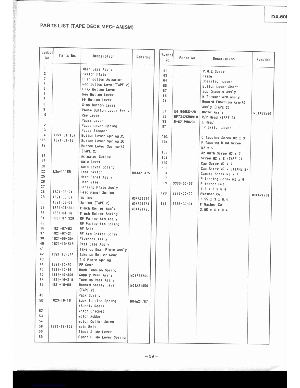
PARTS
LIST
(TAPE
DECK
MECHANISM)
Parts
No.
Descriotion
I
2
3
4
5
6
7
I
I
t0
tl
t2
t3
l1
't5
t7
t8
t9
?0
22
25
26
27
28
2g
30
32
33
31
1ç
36
37
38
10
1l
t2
13
11
15
t6
17
18
52
53
5l
56
59
60
|
82r
-0t
-t
87
|
82t
-01
-l
3
LSA-
il t 5R
| 821
-03-2t
|
82t
-03-07
| 82t
-03-08
| 82t
-0t-301
| 82r
-01-l
0
|
82r
-07-328
r
82r
-07-03
l82t
-07 -21
| 82r
-09-30{
t82r-t0-st5
r82t-t0-31A
r82l-r0-70
t82l-r0-t6
l82t-10-309
t82t-10-319
t82r-t0-6s
1829-t0-t0
l82r-t2-138
llain
Base
Ass'y
Sui
tch
Plate
Push
Botton
Actuator
Rec
Button
Lever(TApE
Z)
Play
Button
Lever
Rey
Button
Lever
FF
Button
Leyer
Stop
Button
Lever
Pause
Eutton
Lever
Ass'y
Rew
Lever
Pause
Lever
Pause
Lever
Spring
Pause
Stopper
Button
Lever
Spr
inS(C)
Button
Lever
Sprins(D)
Button
Lever
Spring(A)
(TAPE
2)
Actuator
Spr inc
Auto
Lever
Auto
Lever
Spring
Leaf
Syi
tch
Head
Panel
Ass'y
Head
Base
Sensing
Plate
Ass'y
Head
Panel
Spring
Spring
Sprinc
(TAPE
2)
Pinch
Rot
ler
Ass'y
Pinch
Rol
ler
Spring
RF
Pulley
Arn
Ass'y
RF Pulley
Arm
Spring
RF
Eelt
RF Arm
Col
lar
Screw
Flyrheel
Ass'y
Reel
Base
Ass'y
Take
up
Gear
Plate
Ass'y
Take
up
Rol
ler
Gear
T.c.Ptate
Sprino
FF
Gear
Back
Tension
Spring
Supply
Reel
Ass'y
Take
up
Reel
Ass'y
Record
Safety
Lever
(TAPE
2)
Pack
Spring
Back Tension
Sprinc
(Supply
Reel)
Xotor
Eracket
totor
Rubber
llotor
Collar
Screw
llain
Bell
Eject
Sl ide
Lever
Eject
Sl
ide
Lever
Spring
lt()rA2l375
r01A2
|
763
lr0{A2l
761
r0{42
| 720
x01A23700
il(l442
| 650
t01A2l
767
Parls
llo.
DescriDtion
6l
Aî
64
65
67
68
7l
8l
82
83
87
r03
t04
t08
r09
il0
ill
I l3
l17
il9
120
t2l
EG
5()(lKD.28
RP73{2CR09t
0
E-
62 | Plt()23
|
9999-03-07
9875-00-00
9999-
00-
0 I
P.
ll.
E
Screw
Frane
Operat
i
on
Lever
Button
Leyer
Shatt
Sub
Chass
i s
Ass'
y
ll.
Tr
icaer
Arn
Ass'y
Record
Function
Arn(A)
Ass'y
(TApE
2)
Lotor
Ass'y
R,/P
Head
(TAPE
Z)
E-Head
FR
S*itch
Lever
C
Tapping
Scre*
ll?
x
3
P
Tapping
Bind
Screr
ll2x5
Aziruth
Screw
ll2
x 7
Screr
12
x
8
(IApE
2)
CaD
Screr
12
x l
Cap
Screr
12
x
S(TAPE
2)
Canera
Screy
12
x 7
P Tapping
Screr
t2
x
6
P
tasher
Cut
1.2
x
3 x
0.{
PHasher
Cut
1.55
x
3 x
0.1
P
lasher
Cut
2.05
x I
x
0.1
r0{A2
3550
I0{A2
t 78
|
Page 12

6.
Removing
the Tuner P.C.B.
(Fig.
5/6)
t
l
Remove 5
screws
@.
(Fig.
S)
2) Remove
screw
(9).
(Fig.6)
7.
Removing
ûre Front Panel
(Fig.7161215l
1l Remove
the
power
switch
link.
(Fig.
7)
2)
Remove
the
speaker
terminal
and
battery
socket
on the
back.
Remove
2 screws
@.
tf
ig.
St
3) Remove
8 screws
@.
iÉ,nr.2,G)
The
front
panel
can
-
now
be removed.
The front P.C.B.,
cassette
p.C.B.
and
cassette
mechanism
ass'y
are removéd
together
with
the
front
panel.
POWER
S W LINK
Fig.7
8. Removing
the Front
P.C.B.
and
Gassette
p.C.B.
(Fig.
gl
1)
Remove
11
screws
@).
fne
front
p.C.B.
can now
tre
removed.
2) Remove
2 screws
@.
ffr"
cassette
p.C.B.
can
now be
removed.
F
RONT
PANE
L
FRONT
PANEL
Fig.
5
Fig.6
ililililililililililililililil11
11ilil1ilililililililililililil1
ililil1il1ililililililililililt1
:
ilililililiilililil1ilt11ililil1
@
ntnilmultttnntttl
'
^
il|ililil|--
-'l
"lllll_-___l'.
SPEAKER P
C B
POWERSWP.CB.
,l
CASSETTE P.C.B
-8
-
Fis.8
Page 13
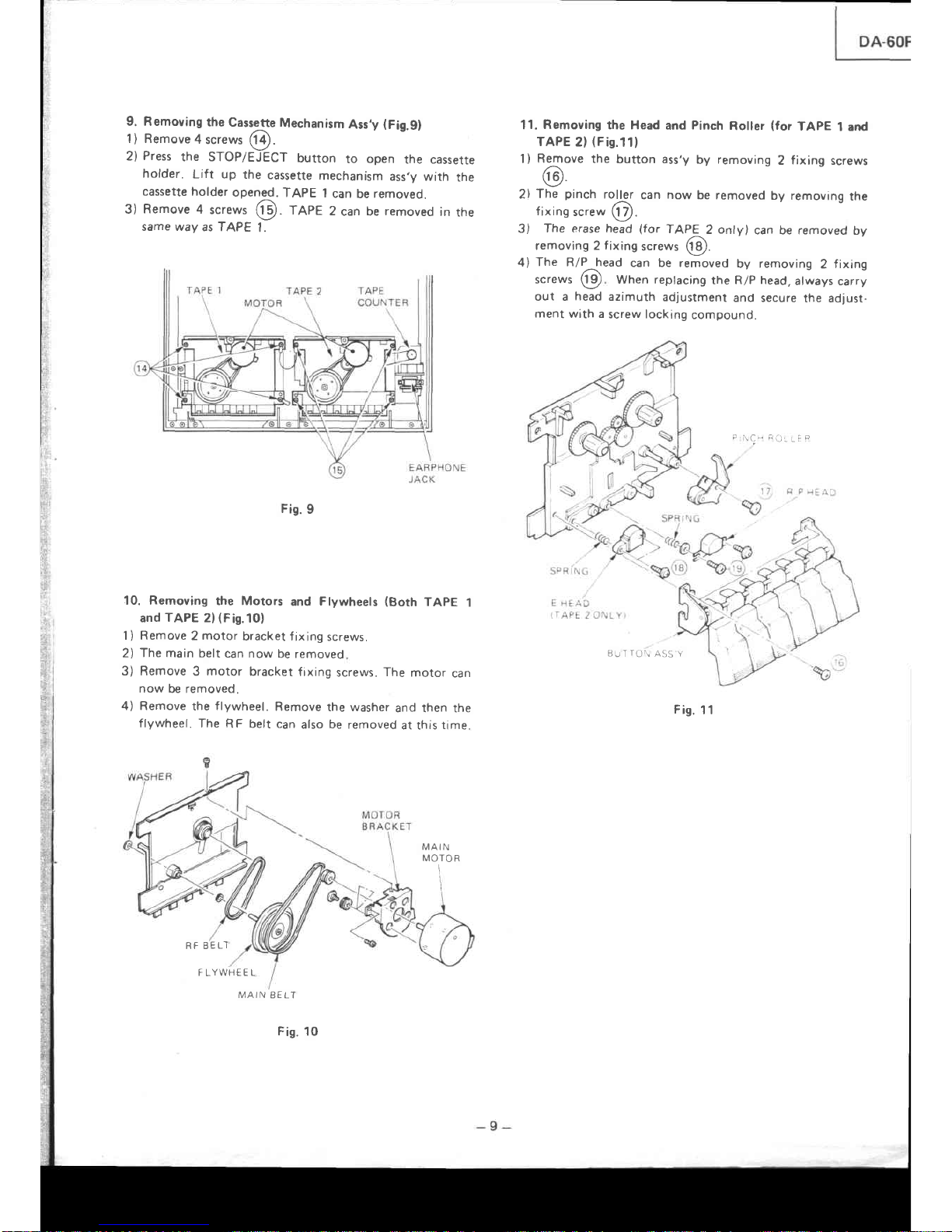
9. Removing
the
Cassette
Mechanism
Ass,y
(Fig.9)
1) Remove
4
screws
6à.
2)
Press
the STOP/ÈiECT
button
to
open
the cassetre
holder.
Lift up
the
cassette
mechanism
ass,y with
the
cassette holder
opened.
TAPE
I
can
be
removeo.
3)
Remove
4
screws
@.
feee
2
can be
removed
in
the
same way
as TAPE
I
Fis.
9
10. Removing
the Motors
and
Flywheels
(Both
TAPE
1
and
TAPE
2)(Fis.10)
1 ) Remove 2 motor
bracket f
ixing screws.
2)
The
main belt
can now
be removed
3) Remove 3 motor
bracket
fixing
screws.
The
motor
can
now
be removed.
4) Remove
the
flywheel.
Remove
the washer
and then the
flywheel.
The
RF belt can
also
be
removed
at this
time.
MAIN
MOTOR
I
FLYWHEEL
11.
Removing
the Head
and
Pinch
Roller
(for
TAPE
l and
TAPE
2l
(Fig.11)
1)
Remove
the
bufton ass'y
by
removing
2
fixrng
screws
(9
2l
The
pinch
roller
can
now
be removed
by removing
the
fixing
screw
O.
3)
The erase head
(for
TAPE
2
only)
can be removed
by
removing 2 f ixing
screws
Qf
.
4)
The R/P_head
can be removed
by removing
2
fixing
screws
(p
When
replacing
the
R/P head,
always
carry
out a
head
azimuth
adjustment
and secure
the adlust-
ment
wilh a
screw locking
compound.
P
\C-
ÊO:
iÊ
e
BUTTO\
ASS Y
Fis.
11
RF BELT
MAIN
EELT
Fis.
10
Page 14

I
pA-60R
I
EXPLODED
VIEW
OF
MECHANISM
(TAPE
DECK)
ilo
{,
ro8
\
I
"---@
&.@
ru)
J
35
L
g--eo
Page 15

DfSC
TRAY
DA-6OR
SERVO
P
C-8
12.
Removal
of
Disc
Tray
Ass,y
1)
Remove
4
screws
Q)
.
Gig.
lzl
2l Pull
Disc
Tray
Ass,y
forward.
Then
pull
off
Disc
Tray
Ass'y
by
pressing
the
hooks
@
in
Fig.
13.
13.
Removal
of
Frapper
Pull
off
the
Frapper
by
pressing
the
hook
@
in
f
ig.
t+.
14.
Removing
the
SERVO
p.G.B.
Remove
4
screws
éD
lFig.
121
and
then
remove
the
SERVO
P.C.B.
V
Fig.
14
15.
Removal
of
pick-up
Remove
3
screws
@
(Fig.
ls)
and
then
remove
the
Pick-up.
Fis.
ts
Fis.
12
Fig.
13
Page 16

PARTS
LIST
(CABINET}
DescriPtion
Parts
No.
t|04A23500
M04
423501
M04AZ
I 480
M04424
4
90
}t04A2449
I
ToP
Cover
Poner
Trans
(EU)
Poter
Trans
(UK)
Chassis
(CD)
Holder
Bat
terY
Case
Speaker
Terninal
Cabinet
Back
Holder
AC
Cord
(EU)
AC
Cord
(UK)
Ter|ni
nal
Flapper
Spring
C0
llecha
Ass'Y
Lâser
Pick-uP
(llLP-7)
Li
fter
(R)
Li
fter
(L)
Disc
TraY
Ass'Y
Lid
Holder
Holder
P. C.
B
Ass'Y
Bush
i ns
Bush
i ns
Holder
Ho
I
der
Push
Button
(Poser
SII)
Shatt
(Pouer Sll)
Holder
P.
C.
B
Ass'Y
Cushion
Gum
Holder
Ho
I
der
P.C.B
Ass'Y
(CD)
P.
C.
B
Ass' Y
(Hai
n)
Heat
Sink
P.
C.
B
Ass'Y
(Tuner)
P.C.B
Àss'Y
(Control)
Felt
Push
Bution
(Function)
Holder
Lag
Te
rrn
i
na
I
Holder
P.C.B
Ass'Y
(Deck)
Botton
Cover
I 11
4-08s01
5584-10251
S
5584-70351
9
| 321
-F00202
421
l-157
{l
6l
-0s21
2
4l6l-16051
IILP
-
7
1
152-04203
l 662-223601
TB
2601
-F0l
3
|
662-24209
I
L
L
J
I
5
6
7
I
I
s
10
1l
IL
IJ
t1
l5
16
l7
18
19
2g
?l
??
23
21
25
26
27
?8
?9
30
3l
32
33
31
35
37
38
3S
10
Description
Parts
ltlo.
Foot
ilecha
Ass'Y
(TAPE-l)
ilecha
Ass'Y
(TAPE-2)
Ho
I der
Holder
Holder
Holder
Holder
Danpe
r
Push
BilGn
(PRE/tIETO/OPEN)
Front
Panel
Ass'Y
2
Knob
Sl
ide
Spring
Case
Lid
Ass'Y-2
Case
Lid
Ass'Y-l
Holder
Ho
I der
Holder
P.
C.
B
Àss'Y
P.
C. B
Ass'Y
Push
button
(
[IODE/
SYN/SPEED
/DOLBY
)
Push
Button
(BASS)
Counter
Bel
t
(counter)
Ho
I
der
Ho
I
der
Screu
TransPort
T-screv
3
x
6
Pan
Head
Screw
3
x
8
T-screu
3
x
6
T-screw
3
x
6
I-screw
3
x
6
Screy
1t2.5
x
{
$asher
ô3.5
x
l0
x
0'6
T-screw
3
x
I
T-screw
3
x
l0
Tasher
ô5'4
x
l0
x
l0
Screr
lt3
x
6
1-scres
I
x
Ê
I-screw
I
x
8
Screu
il3
x
14
Screw
t{3
x
l0
I 3t
9-F001
0l
2692-
1 3
r66tt{03
1612'12201
2651
-000021
6
1
5l
I
-05307
1
662-30601
3l
3l
-035020
2ô12-01
t5t
Page 17

TUNER SECTION ADJUSTMENT
No.
Measured
Item
Input/Output
and Procedure
Point
of
Adjustment
Adlustment
for Remarks
1 AM
IF
Adjustment
"MW mode"
.
Set
the I F sweep
frequency
to 450 kHz.
.
Connect lF sweep's
OUT
terminal to
loop
antenna.
lF
sweeo's
lN terminal to R511.
T502 Adjust T502 so that wave-
form is
maximized and
symmetrical as
in
Frg
'l
6
See
Fig.
18
2
FM
IF
Adjustment
"FM mode"
(Coarsel
o
Set
the lF sweep
frequency
to
10.7
MHz.
o
Connect
lF sweep's
OUT
terminal to
R503.
lF
sweep's
lN terminal to R511.
T501 Adjust T501 so that wave-
form is maximized and
symmetrical
as
in
Fig
17
See Fig.
'19
3 FM VCO
Check
"FM
mode"
.
Connect
digital
voltmeter across
R557
.
Set
the
function
to the
FM
position.
the
reception
frequency to
87.5
MHz
and
check to
make
sure that
voltaqe
is 1.6
V.
o
Set
frequency to I 08
MHz
and check
to
make
sure that
voltage is 8 V
See
Fis 20
4 FM
IF
Adjustment
"FM mode"
(Fine)
o
Set the
FM signal
generator
to
98MHz
and connect
it
to
the FM antenna
terminal through
the 300S1 balanced
dummy.
(signal
level 1mV)
o
Set
the f unction to the
FM
oosition
and
the
reception
frequency
to
98MHz.
.
Connect the distortion meter to the
audio output.
T501
Adjust
so that the audio
output
in minimum
dis-
tortron.
See
F ig
a1
5 MW VCO
Adjustment
o
Connect digital
voltmeter
across R517.
.
Set
the function to the MW
position,
the reception
frequency
to 522kHz
(minimum
frequency).
1505
Adjust
L505
until voltage
becomes'l 41005V.
See
F ig
20
a
Set
the reception
frequency
to
1,620kH2 ( maximum
frequency).
TC502 Adjust fC502 until voltage
becomes
8.0
10.05V.
Repeatsteps
minimum and maximum
frequency two
or three times until both
adjust-
ment are at best level.
6
MW
Tracking
Adjustment
o
Radiate each of
the
tracking
point
frequencies
given
below
from
the
AM
test
loop
(signal
level 56dB/m).
.
Receive
each
of the
tracking
point
frequencies
given
below
by means
of
the key or
Tuning
Up/Down
Switch.
o
Connect
the AC
voltmeter to
the
audio output.
1504
TC501
Adjust so that the
output
is
maximized at each track-
Ing
pornt.
See
Fig
22
-
11
-
Page 18

EXPLODED
VIEW
OF
CABINET
Page 19

JP252
JP253
JPz51
JP255
JP258
JPz59
JP26()
JPz6
I
JPz62
JP2ô3
JP261
JP265
JP266
c2
cl
cl
cl
D?
D?
o?
D2
A6
D2
D2
c2
c3
c3
c3
D3
D3
DI
cl
c3
0{
01
E{
E1
E{
E{
DI
c5
c5
D5
D5
A2
83
B3
A1
B1
c1
8{
B{
B{
B5
A5
c5
c5
A6
BI
c5
c6
o2
c5
JP28(}
JP282
JPz83
JP289
JP3(l(]
JP30
I
JP3()2
JP3()3
JP3O1
JP3(}5
JP3(l6
JP3()7
JP3(}8
JP3()9
c2
E3
Ê3
rJ
E3
E3
DI
D1
D{
D1
D5
D5
D5
D6
D6
c6
c6
B2
c6
E5
E6
cl
83
c6
A3
AI
A{
A5
A5
A3
A3
B1
A2
A2
82
82
D2
DI
DI
E3
0{
B5
B5
g?
s2
D5
UD
LD
AE
D6
D5
E5
c6
c5
A3
A3
A1
A4
A3
A1
lA4
A1
Al
A4
A5
A5
A5
A5
A3
83
A3
A3
B3
83
81
81
B3
B{
c3
BI
B1
85
B1
85
BI
B5
B1
B5
n(
c1
c1
R283
R281
R285
R286
R288
R289
R290
R29
I
R292
R291
R2
95
R296
R29
7
RU 98
R300
R3()I
AI
AI
AI
BI
BI
A?
8l
8l
BI
BI
BI
BI
BI
cl
cl
cl
cl
DI
DI
DI
DI
DI
c1
B3
85
B5
B2
BZ
B2
B2
E3
E3
05
D5
E7
DI
E2
D2
D2
D5
E6
D6
D6
D6
E5
E5
D6
E3
A3
A2
AZ
E3
UL
E2
lPZ0l
TP2O?
TP2()
3
Page 20

DA.6OR
Input/Output
and
procedure
MW
Tracking
Adjustment
*
Tracking
point
frequency
1,404
kïz
999
kHz
603
kHz
Repeat
adjustment
at
each
tracking
point
alternately.
LW
VCO
Adjustment
Adjust
L5O7
until
voltage
becomes
'1
.4
I
O.OSV.
See
Fig.
20
Set
the
reception
frequency
to
maxi-
mum
frequency.
Adjust
TCS04
until
voltage
becomes
8.0
t
0.0S
V.
Repeat
steps
minimum
and
maximum
frequency
two
or
ment
are
at
best
level.
three
times
until
both
adjust-
LW
Tracking
Adjustment
o
Radiate
each
of
the
tracking
point
frequencies
given
below
from
the
AM
rest
loop
(signal
level56dB/ml.
.
Receive
each
of
the
tracking
point
frequencies
given
below
by
means
of
the
key
or
Tuning
Up/Down
Switch.
o
Connect
the
AC
voltmerer
to
the
audio
output.
*
Tracking
point
frequency
344
kHz
254
kHz
164
kHz
_15-06_ |
eAiust
so
that
the
outpul
TC503
[
is
maximized
at
each
track-
See Fig.
22
Repeat
adjustment
at
each
tracking
point
alternately.
19kHz
leak
check
o
Input
a
98MHz
(lkHz
100%
modula_
tion
l
mV)
stereo
signal
to
the
FM
antenna
terminal
using
the
FM
signal
generator.
o
Receive
the
ggMHz
signal.
r
Turn
off
the
modulation
of
the
FM
signal
generator
(only
with
pilot
signal).
.
Connect
the
AC
voltmeter
to
AUDIO
OUT.
LPF50l
LPF5O2
Check
that
the
leakage
of
the
l9kHz
signal
from
both
Lch
and
Bch
is
less
than
SmV.
lf
it
is
not
less
than
SmV,
adjust
LFFSOI
and
LPF502
so
rhat
the
leakage
is
minimized.
See
Fig.
21
Fig.
Page 21

I
I
I
t^
I
DA-l
Symbo
I
No
R308
R309
R3l0
R3l l
R3l
2
R3r3
KJ IJ
Zone
No
D2
1?
ct
BI
82
TP2()I
IP202
ïP203
t{t0l
rf
t02
x20
|
E4
E3
83
8l
02
c4
JPzI6
JP2I
I
JPzI
8
JPzI
9
JP22I
JP222
JP223
JP224
JP225
JP227
JP2?8
JP2
3()
JPz1
4
JP215
JP2
16
JPz17
JP248
JPz19
JP25I
JP252
JP253
JP25
4
JP255
JP258
JP259
JP26()
c2
c2
c2
c3
c2
cl
cl
cl
D2
D?
D2
D2
A6
UL
D2
VL
LJ
LJ
c3
03
D3
D4
c1
n?
D1
D1
E1
E4
E1
E1
D4
c5
(,f,
D5
05
A2
B3
B3
A1
81
c1
B4
B1
8{
B5
A5
c5
c5
Aô
84
c5
c6
D?
JP28()
JP282
JP28
3
JP28
9
JP3OO
JP3(l
I
JP3O2
JP3()3
JP3(){
JP3O5
JP3O6
JP3O7
JP3()8
JP3()9
JP3I
()
Rç
Ftç
A5
c5
8t
EI
EI
c2
E3
E3
E3
ÈJ
D1
D1
D1
D1
D5
D5
D5
D6
06
c6
c6
B2
c6
Ê5
E6
c1
B3
c6
A3
A1
Al
A5
A5
A3
A3
84
A2
A2
B2
B2
D2
0l
0l
ÈJ
D1
B5
B5
B2
B2
E6
AZ
A?
A3
A3
1'
EI
EI
D5
c6
c6
D6
D5
E5
c6
c6
Â3
A3
A4
A4
A3
A4
A4
A4
A4
A4
A5
A5
A5
A5
A3
B3
A3
A3
B3
B3
B1
84
B3
B1
c3
B1
B{
B5
B4
B5
B1
B5
B4
B5
aç
c1
c1
AI
AI
A'I
BI
BI
A?
8l
BI
BI
BI
BI
BI
BI
cl
cl
cl
cl
DI
DI
DI
DI
DI
c4
B3
85
B5
B2
P,2
BZ
B2
E3
EJ
Page 22

No.
Measured
Item
Input/Output
and Procedure
Point
of
Adiustment
Adjustment
for
Remarks
6 MW
Tracking
Adjustment
Tracking
point
f
requency
1,404
kHz
999 kHz
603 kHz
Repeat
adjustment
at each
tracking point
alternately.
7
LW VCO
Adjustment
o
Connect
digital
voltmeter
across
RS29.
Set the
function
to the
LW
position,
the
reception
frequency
to
minimum
frequency.
a
L507
Adlust
L507
until
voltage
becomes
1.4
I
0.O5V.
See
Fig.20
o
Set
the
reception
frequency
to
maxi-
mum
frequency.
TC504
Adjust
TC504
until voltage
beçomes
8.01
0.05 V.
Repeat
steps
minimum
and
maximum
frequency
two or
three
times
until
both
adjust-
ment
are
at
best
level.
I
LW
Tracking
Adlustment
o
Radiate
each
of the
tracking
point
frequencies
given
below
from
the
AM
test
loop
(signal
levelS6dB/m).
o
Receive
each
of
the tracking
point
frequencies
given
below
by
means
of
the
key
or
Tuning
Up/Down
Switch.
.
Connect
the
AC
voltmeter
to the
audio
output.
*
Tracking point
frequency
344
kHz
254kHz
164
kHz
1506
TC503
Adjust
so that
the
output
is
maximized
at
each
track.
ing
point.
See
Fig.22
Repeat
adjustment
at
each
tracking
point
alternately.
9 l9kHz
leak
check
.
Input
a 98MHz
(lkHz
lO0%
modula-
tion
I
mV)
stereo
signal
to
the
FM
antenna
terminal
using
the
FM
signal
generator.
o
Receive
the
98MHz
signal.
o
Turn
off
the
modulation
of the
FM
signal generator (only
with
pilot
signal).
o
Connect
the
AC
voltmeter
to AUDIO
OUT.
LPF501
LPF5O2
Check
that
the leakage
of
the
l9kHz
signal
from
both
Lch
and
Rch
is less
than
SmV.
lf
it is
not
less than
5mV,
adjust
LFF501
and
LPF502
so
that
the
leakage
is
minimized.
See Fig.21
Page 23

AM
ANTENNA
Fis.
20
Fig.21
Fis.22
Fig.
19
ADJUSTMENT
POINT
(TUNER
SECTION)
FM
FRONT
END
BALANCED
DUMMY
50o
---
300a
DISTORTION
METE
R
AC
VOLT
I\4ETER
Page 24
65
lg
'o
0l
B4
1E
C2
FI
6L
D1
DI
A2
A2
B1
B2
LJ
c2
D6
D3
D3
B4
82
DI
D4
D5
D5
B3
B2
E3
8t
B3
c6
D3
C2
CI
E2
ct
AI
A1
AI
A2
A2
A2
B2
B2
B2
82
B2
B2
A2
A2
c2s5
020 |
D?02
D203
0204
D2 06
D207
0208
D2OS
D2l 0
D2l 1
Dzt2
D2l 3
021 4
GNO
I
GND 2
rcil0
I
c20t
I C202
tc203
1c204
I c205
rc206
tc207
tc209
J?01
J2g2
J203
J20s
J206
J50 r
J60l
J602
J603
J6r 3
JL2OI
JP2OI
JP2O2
JP2O3
JP2O4
JP2O5
JPZO 6
JP2O1
JP2O8
JPZO9
JP21O
JP2II
JPzI2
JP213
JPZI 4
JP2I5
dE
la
l*l*
Rtel
Is';
gl
R2o1
;,
In{n
*c48
rl*
ul
I
NI
Àl
-l
Symbo
I
No.
Zone
No
ct42
cr 43
ct 44
cr 45
c1 47
c148
c20l
c202
c203
c204
c205
c2 06
c208
c209
c210
c2l 1
c21 2
c2r 3
c2t4
c21
5
c216
c211
c2t8
c2rI
c?20
c221
c222
c?23
c224
c?25
c226
c227
c22B
c229
c23 l
c232
c233
c234
c236
c231
c238
c239
c240
c2 41
c242
c243
c244
c245
c248
c249
c250
c25t
c?52
c253
04
c6
D6
D6
B1
UO
A4
A4
A5
A3
B3
84
B4
B4
B4
B5
B5
B4
c5
C4
AI
AI
8l
BI
6t
D1
c4
D4
D5
c5
C4
D4
B5
OJ
.E
C5
D2
02
e1
c2
D5
E6
D6
D6
D6
D2
A1
A2
B2
D1
-54 -
Page 25

DA-6OR
TAPE
DECK
SECTION
ADJUSTMENT
Before
adjustment
'
Make
sure
to carry
out
the steps
1
to 3
of
"1.
Mechanism
adjustment"
before
attempting
electrical
adjustment,
or
the
test
tape may
get
damaged.
o
To
prevent
measurement
error
due
to magnetization
or
dirt,
be sure
to carry
out
head
degausing
and head-cleaning.
1. MECHANICAL
ADJUSTMENT
Step
Item
Test tape
tools used
Output
terminal
test
poant
Adjustment
point
Adjustment
for
Remarks
1
Tape
1
Speed
Adjustment
TAPE
1
stan-
dard
3kHz,
-10d8
(TCC-112
or
MTT-1
1
1)
Connect
the
Frequency
counter
to
TP301
or
TP401.
VR3O5
Playback
mode
2,97OHz
TAPE
1
double
speed
V
R3O6
Dubbing mode
5,940H2
Load
a blank
a
cassette
tape
in
the
TAPE
2
mechanism
so
that
the
dubbing
mode
is
obtained.
2 Tape 2
Speed
Adjustment
TAPE
2
stan-
dard
3kHz,
-'l
OdB
(TCC-
1 12
or
MTT-111)
Connect
the
Frequency
counter
to
TP301
or
TP401.
VR3O7
Playback
mode
2,960H2
TAPE
2
double
speed
VR3O8
Dubbing
mode
5,92OHz
Adjust
so rhat
the output
levels
ofLandRchannels
are in
the
same
phase
at
môxlmum.
Adjust
on both
TAPE
I and
TAPE
2 mecha-
nrsm.
During
the dub-
bing
operation,
the
TAPE
2
mechanism
is
in
the
REC
mode.
and
will
therefore
erase
the
test
tape.
To
prevent
this,
place
the
unit
in
the
play-
back
operation
by
shorting
the
part
as
shown
in
f
igu
re.
3
Head
azimuth
Adjustment
l0kHz,
-10d8
(TCC.173A
or MTT-
114)
Connect
VTVM
and
the
oscilloscope
to
TP30l
or
TP401.
Head
Azimuth
Adjustment
screw
See
Fig.
23
-14-
Page 26

CD
P.C.B
-53-
Page 27

D6
aa
aa
LO
c6
D5
D5
06
c9
Ub
E8
E9
D9
D9
L5
E9
D8
E8
D8
E8
D8
D8
09
E9
E7
05
E5
E5
D6
E8
06
06
E6
E1
E6
E6
E6
E6
B8
E2
E2
E2
EI
EI
B5
c5
DI
D2
D2
D3
c60l
c602
c603
c604
c605
c606
c607
c608
c609
c6r
0
c6l
I
c6A
I
c70l
c7
02
c703
c704
c705
c706
c707
c708
c709
c7l
0
c7r
I
c71?
c7l
3
c7l4
c80
I
c802
c803
c804
c805
c806
c807
c808
c80
I
c8r0
c8rr
c8l
2
c8l3
c8l
4
cF60r
D8l
082
D83
084
085
D602
0603
D4
D4
E3
c6
09
D9
r.ç
E5
0s
E5
B3
85
B8
B7
c6
c6
D6
E2
E4
LL
E3
E7
LD
EI
EI
DI
c2
0l
D2
VL
D2
DI
D2
tra
E3
D2
^2
c3
UJ
D3
LJ
E3
LJ
ai
D3
c4
c4
c4
c4
Dô09
D6l
0
D6l
I
D622
0623
0624
D625
I cô0r
I c602
I c603
I c70r
I c80l
J6r0
JbIJ
JL6O
I
JL6O2
JL6O3
JL6O4
JL6()5
JL6()6
JL6O7
JL6()8
JL6O9
JL6I3
JL6I6
JPI
JPI
JP2
JP3
JP4
JP7
JP8
JP9
JP8
JPI
O
JPII
JPI3
JPI4
JPI 5
JPI
6
JPIT
JPIS
JPI9
D4
D5
D5
B5
c6
E5
E5
B6
Lb
LO
tD
E6
n7
11
c8
na
07
E7
D8
E8
D8
E8
E8
E8
E8
D9
c9
c9
ao
C8
nq
nq
C8
LÔ
B9
E4
tJ
E3
D3
D4
D4
05
D6
Dô
E8
E1
E8
JP4I
JP 42
JP43
JP4
5
JP46
JP4
7
JP48
JP4
9
JP5
O
JP5
I
JP5 3
JP5
4
JP5
7
JP5 9
JP6t]
JP6
I
JP6 2
JP6 3
JP6
4
JP65
JP66
JP6
7
JPô8
JPT()
JP7
I
JP73
JP7
4
JP7
5
JP76
JPl
7
JP7 8
JP 8O
JP8
I
JP8 2
JP83
JP8
4
JP85
JP86
JP87
JP8
8
rpeq
JP92
JP93
JP94
JP96
JP9 7
JP98
JP99
JPI OO
JPIt)I
JPI
()2
JPI
()3
JPI
Ol
JPI
O5
JPI
O6
JPIOS
JPIO9
JPIIO
L60l
1602
1603
Q60l
Q602
Q603
R6r
R9l
RS2
R93
R94
R9s
R60l
R602
R60 3
R604
R605
R606
R607
R608
R609
R6r0
R6l 4
R5l
5
R6l6
R6l 7
R622
R624
R626
R626
R6 30
R63
r
R632
R633
R634
R635
R636
R637
R638
R639
R640
R64
I
R642
R643
R644
R645
R646
R647
R648
D5
E7
LO
D5
D9
D8
D4
E6
E2
E2
E2
EZ
E2
LO
B8
04
D4
03
D3
B7
B7
B7
B7
c9
na
c8
nq
B6
B6
E3
E1
E3
c1
c1
c4
c4
c1
04
D4
04
NE
c5
c5
B6
B6
B6
Symbo
I
No
R 619
R650
R65 I
R652
R653
R654
R655
Rô57
R658
R659
R664
R665
R666
R66
7
R668
R669
R670
R67r
R672
R673
R674
R675
R676
Zone
No.
R677
R678
R679
Rô80
R68 I
R682
R683
R681
R6 85
R686
R687
R688
R689
R690
R702
R703
R802
R803
s60 l
s602
s603
s606
s607
s60 I
s609
s5l0
s6l I
B6
B6
B6
B6
B6
B6
B6
B8
B7
a7
B8
ce
^e
Ld
UO
c8
Ld
17
17
c7
n7
c7
c7
c7
c7
C7
c6
NA
c6
cô
D9
E9
E5
E5
A1
A4
A3
A2
^2
B1
B1
B3
B3
B3
B2
6t
BI
s6l 2
5b I J
s6l 4
s6r5
5b tb
s5r7
s6r I
s6l
I
JDIU
s62
I
JDZZ
JbZJ
s621
s625
s626
s627
s628
VR78I
VR78Z
VR783
VR784
VR785
VR786
tll684
H686
t{687
fr688
yi689
t{690
t{690
-51
-
Page 28

F1
FUSE
P.C.B
REMOTE
CONTROL
P.C.B
POWER
SW
P.C.B
oR4
PRESET
CHANNEL
CD
-30-o100
-l.-
D4
-{a-
D6
-*l-
D5
_{.-
D7
{F
{F
cr
c2
rc
Page 29

ululnl
,'lnls
ls ls
iE rË
c255
D20
1
D202
0203
0204
0206
0207
D208
D209
D2r0
D2tI
Dzt 2
D2r3
Dzt 4
tcil0
lc20l
I c202
I c203
tc204
I
c205
r c206
tc207
1c209
J20l
J202
J203
J205
J206
J50l
J60l
J602
J603
J6l3
JL2OI
JP2O I
JP2O2
JP2O3
JP2O4
JP2O5
JP2O6
JP207
JP2OB
JP2O9
JP2IO
JP2I I
JPzI2
JP2I3
JP2I4
JP2]5
DI
B1
nt
Ë'l
c1
DI
0l
A2
A2
8r
B2
c3
c2
D6
D3
03
84
B2
0l
D1
D5
D5
B3
B2
E3
B1
B3
c6
D3
It
C]
E2
ç,
AI
AI
A2
^2
A2
B2
B2
B2
82
B2
82
A?
^2
C2
lc
lgpinlr
lr
GND
I
GND2
,nn
lulx
E
uH
Ë
f;
'Ëlmln,alu
.t$
Ër8r
C2t8
l*lt
nt01
la;':
*l
RI
-l
I
Synbo
I I Zone
No.
I
No
ct42
|
Ol
cl43 |
C6
cr44
I
D6
cr45
|
D6
cr47
I
Bl
cl48 |
c6
c2or
I
A4
c202 |
A4
c203
I
As
c204
I
A3
c20s
|
83
c206
|
84
c208
|
84
c209
|
el
c2r0
|
84
c2r
I
85
c212
|
85
c2r3 |
84
c2l4
|
C5
c2l5 I C4
c2r6 | c4
c217 | Al
c2r8
|
ar
c2r9
|
Bl
c220
|
Br
c22t I c4
c222 |
82
c2?3
i
Dl
c224 I C4
c225
|
C4
c226
i
Cq
c227 I D4
c228
|
Ds
c229 I C5
c23l
I
C4
c232
I
D4
c233 I 85
c234 | 83
c236
|
C5
c?31
| C5
c238 I 02
c239 l D2
c240
I
cr
c241 I C2
c242 | D5
c243
|
E6
c244
I
D6
c24s I D6
c248
i
D6
c249
|
D2
c250
|
A1
c251
| A2
c252
|
82
c2s3
I
Dl
c254 |
C4
Page 30

CD P.C.B
Page 31

2. PLAYBACK
ADJUSTMENT
*
Proceed
with the
playback
adjustments
after
having
finished
the mechanical
adiustments.
3.
RECORD/PLAYBAC
K
ADJUSTMENT
Step
Item
Test
tape
Output
terminaU
test
point
Adjustment
pornt
Adjustment
for
Remarks
1 Playback
Level
Adiustment
400H2,
200mWb/m
(TCC-130
or
MTT.150)
Connect
the
VTVM
to
TP301
(L
ch),
TP40'l
(R
ch).
TAPE
1
VR301
(L
ch)
VR401
(R
ch)
TP30'l:
580mV
TP401:
580mV
Connect
the
VTVM
to
TP301
(L
ch),
ïP401
(R
ch).
TAPE
2
VR302
(L
ch)
VR402
(R
ch)
TP301:580mV
TP401:
580mV
Step
Item
I nput
terminal/
signal
Test tape
Output
terminal/
test
polnt
Adlustment
pornt
Adjustment
for
Remarks
1
Bias
F requency
C ha
racteristic
Adjustment
(TAPE
2}
Load the
cassette
tape
(Special:
AC-5'l 2 ) and
set for recordIng
Connect
the
frequency
counter
to
both
sides
of
R3',I5
osc301
(BIAS
OSC)
103kHz I
3
kHz
2 Bias
Level
Adjustment
(TAPE
2)
Load
the
cassette
tape
and set for
record
ing.
Special
AC.512
Normal:
TCC-',l02A
Connect
the
VTVM
and
d istort
ion
meter
10 the
both sides
of
R315
(L
ch),
R415
(R
ch).
VR304
(
L ch)
VR404
(R
ch)
Normal:
2'l mV
Special:
21mV
+23d8
l26mV)
Temporary
ad
justment
3 Record
Level
Adjustment
(TAPE
2)
AUX
400H2,
300mV
Load the
cassette
tape
(Special:
AC-512)
and
set
f
or recording
Connect
the
VTVM
to
TP301
(L
ch),
TP401
(R
ch)
V R3O3
(L
ch)
V
R4O3
(R
ch)
REC VR
o
Set
REC
VR
so that
output
vottage
to
580mV.
r
Adjust
VR303
(L
ch)
and
VR403
(R
ch)
so that
outpul
voltage
to
580mV.
Page 32

l
5l
6
7
l8t
9
)
JP50
-l*
JO
_18
Ea4
F333r
_R646
R654-
-R647
R655-
-
R6,48
_R649
-
R650
-R651
cd
rtu '=
tR t6
Ët
rilill
@È@6çÉN
tsÈÈÈÈtsF
@@6@@@@
GÈ
ÈÉÈ
EÈ
!|il
6@q@ots
ÈÈdÈeÈ
ll
IUN
Lô03
06ê2
rt
r€0l
-.-l-
-lE
J-
iIr
rg-rà
f{8
ttù tF
6{5
R642
R643
t-690
[3i3
ceot
16ft{)
\4752
"Ptæ-
I'
t:
lo
l-
ta
l-
c8r0
r*1
r8l
r{le
l4
I
R0t4
RCI É
6ui
66
67
68 Ê8
f61
"F66
-ffi-
Gil
i
F
El Ë
ETTII
ml
+
tE21'
l-
IO
lq
,!s
l3
t-
l6
t1
t'
c8{xt
c81 r
c8r3
rBt:
rDtq
cTlB
Ët8tlÈ
8r'
o'
rH
E*
c806
o7-7
,pf6
c700
Lo'
=ttrl
s'5'
F
ô
6l b C
62 d
e
æNCÊ.ltçS5
mol
JL6o6
æ61
= I r---T---r-l
$l-l
t
I le1
,xl
JP'03
Page 33

Step
Item
Input
terminal
signal
Test
tape
0utput
terminaU
test
point
Adjustment
potnt
Adjustment
for
Remarks
4
Record/
Playback
Freguency
Characteristic
Adlustment
(TAPE
2I
AUX
4O0Hz,
300mV
4OHz
-
12
5kHz
300mV
AC 512
Connect the
VTVM
to
TP301
or
TP4O1,
VR304
(L
ch)
VR404
(R
ch)
Adjust so
that
fraquency
response
ts
within
the
specif ication
when
record-
ing
on the
test
tape
and
play-
ing it
back.
Check
also
at
Dolby
lt\
position.
5
Record Level
lndicator
Adjustment
MTT.150
VR81
Adjust
VR81
so that
REC
LED
(OdB)
lights.
VTVM
Oscilloscope
Low
frequency
osciltator
,|!],
-,Pl
,1"*
lou'lou'1a.enua'1or
î
rÏ
-{Fooo
:l}
r[],11"^*alrenuaro,
Heôd
Azrmurh
Adr
Screw
Fig.23
ADJUSTMENT POINT
(TAPE
DECK
SECTION}
Fis.24
PLAYBACK
LEVE
L ADJ
{TAPE
1
MECHA)
l-iApE
s"EEo AoJ
l
t_!êE_:1l!!I1]J
-16-
Page 34

sôtr|
Ëq
r.
*_'l
II
I
,,,
,:.
I
l'-,_J
s6æ,
FLIY
FRONT
P.C.B
Svlnbo
I
No.
c30l
c302
c303
c304
c305
c30
6
c307
c308
c309
c31
0
c3l
1
c31
5
c31
6
c3l
7
c31
I
c31
I
c320
c3
2l
c37?
c323
c324
c326
c321
c330
c33l
c332
I.JJJ
c334
c336
c337
c338
ôi1o
c340
c3
41
c342
c343
c34
4
alqn
c352
c35
4
c35
s
a"(a
s607
SIæ
sT!
tôfl
l-
to
l-
56l6
TUt
tll
l* lelule
l*
lll
96æ
-
&
I
i
9,t
qr
n-
tE8
tcRill
l-
l''
'B*
'Eg
{cË{1.
{6nN)
I
c
n626
n?q7
c358
c35
I
c360
c36
I
c362
c370
c3i
1
c37
2
c373
c37
4
R63lR632-
I
R635*
R634R635-
R636R637-
lË n-
i-t.t
I
YilÉ
{GRil)
m
r*------__l
tt
lt
tl
ll
sÊts
r'8
'
.
, rrB,,,:
Ex)Hn
uul pg3
s825
V(L
tti
_49-
Page 35

Adlustment
I
Adlustment
for
I
Remarks
Connect
the
VTVM
to
TP301
or
TP40',l.
MTT-150
V
R81
(MainPCB)
Check
also
at
Dolby
I
posltlon.
Adiust
so
thaÏ
frequencY
response
ls
within
the
specif
ication
when
recoro-
ing
on
the
test
rape
and
play-
ing
it
back
V8304
(L
ch)
VR404
(R
ch)
Record/
Playback
F
requencY
Characteristic
Adiustment
(TAPE
2)
Adiust
VR81
so
that
REC
LED
(OdB)
lights.
O9c
rlloscoPe
15
,l-'l
-1[
I
t
Low
trequencY
oscrllalor
r|rl
-rLJr
output
alteôualor
-
il:-ffil
I'
Hl],,."
arrenuaro,
Head
Azrmuth
Adl
Screw
Fig-23
T
POINT
(TAPE DECK
Fis.24
SECTION)
HI
n8{
c8|
ADJUSTMENT
TAPE
SPEED
ADJ
(TAPE l N4ECHA}
P
LAYBAC
K
LEVEL
ADJ
(TAPE
1 MECHA)
BIAS
FREOUENCY
CHA
RACT
E
B IST
IC
ADJ
(Rch)
-
16
-
Page 36

FRONT
P.C.B
s610
s612
5
Symbo
I
No.
c30l
c302
c303
c304
c305
c306
c307
c308
c309
c3l
0
c3l
I
c31 5
c31
6
c3l
7
c3l 8
c3l9
c320
c32 I
VJLL
a?t1
c324
c326
c327
s61t
a
T
T
nn
,P1
s6l6
I I
TLn|
|
*ll
s6r4 s6r3
78
z
È
I
o
o
I
'
l-
l*
c330
c33l
c332
LJJJ
c334
c335
c336
LJJ T
c338
c339
c340
c34
I
c342
c343
c350
c352
c353
c354
c355
le
lelele
t3t3
l*l*
In
I
lo
l-
lil*l*l-l-l'
l-
(enl
liEa
I
t^
l*
ln
*l*l,HF'
sô28
,P2t
m0
R626
lll
,|.0t3
Exf,û{ tf{II
Uæg
LJJO
n1ç7
c359
c360
c36l
c362
c370
UJ I I
c372
LJ I J
c374
'Er*'E*
sôæ
RTY
s607
sïæ
Page 37

Symbo
I
No.
Zone
No.
s333
ur334
vt335
[336
t{337
t{338
w3 39
H3 40
ut3ll
uf342
[343
w34 4
w31 5
u3 46
T 317
It348
H319
ur350
H35
l
v1352
r{353
T354
T355
w356
w35 7
t{358
tf359
t{360
H36 |
w362
t{363
H361
ut365
H366
l|3ô7
l|37
|
u37
3
u37 1
il375
t3
76
H37 7
c7
B5
A5
B5
B1
B4
B4
c4
c1
c5
c1
c1
c1
c4
c3
c3
LJ
c3
BZ
B1
B3
B3
B3
A{
A3
A3
nl
cl
BI
AI
BI
8l
c5
frE
cl
ci
87
A7
c7
c6
c6
c6
c6
c6
c5
c5
c5
c5
c5
c5
c5
c5
c5
aç
Symbo
I
No.
Zone
No.
R159
R460
R46
r
B4
B4
B1
c2
c2
c2
c5
B5
B3
a?
c4
c4
c4
B7
c6
R1
62
R461
R165
R470
R47
3
R4
71
R502
R503
R501
R506
R507
R508
s0c30
|
TP3()
I
TP3O
3
TP4()
I
c3
86
c5
B6
vR30r I
cl
vR302
|
Al
vR303 |
A5
vR301 |
83
vR305
I
C8
vR30ô
|
c8
vR307 |
C7
vR308
|
C8
vR10r I
Bl
vR102
I
Ar
vR103
|
Bs
vR40l I
83
[3t
I
u3r
2
t|3r
3
{3t4
vt3l5
[3t 6
H3l
7
w3r
9
H320
v322
H32 3
t32
I
t3 25
t{326
w327
H32
I
[3 29
H3
30
u3 3l
tl332
B8
B8
B8
B8
B8
B8
c8
c8
c7
A8
B7
B7
B7
A7
c7
B7
B7
B7
87
A7
Symbo I
No.
Zone
No.
$39
|
ft392
w39 3
ut394
H395
u3
96
T397
il398
t399
w4
00
H40
I
H102
w403
w4
01
w405
ut10
6
ut4l
I
I
Page 38

DA.6OR
BI
AI
B'
Bl
B
A
B
B
c
c
A
A
A
B
B
B
B
B
B
B
B
B
B
I
E
E
t
t
t
I
t
I
I
I
I
I
I
I
I
I
R382
R383
R381
R385
R386
R387
R388
R389
R390
R39 |
R392
R393
R394
R395
R396
R397
R398
R{01
R402
R{03
R401
Rt05
R106
R107
R408
R409
R4t 0
Rll
I
R{t5
Rll
6
Rlr
7
R{t8
Rlr
I
R420
R42
|
Rt22
R123
R42{
R126
R127
Rlt
I
Rl42
R143
R{44
R115
R{
46
R45
I
R{52
R{53
R15l
R{55
R156
R157
R458
R326
R327
R328
R330
R33l
R332
R333
R331
R335
R336
R337
R338
R339
R3{0
R34
|
R342
R313
R341
R3{5
R3{6
R3{7
R3{8
R3{9
R350
R35 |
R352
R353
R35{
R355
R356
R3s7
R358
R359
R360
R36 I
R362
R363
R364
R365
R366
R367
R368
R369
R370
R37 |
R372
R373
R37l
R375
R376
R377
R378
AI
AI
82
c7
B8
A7
B3
B3
B4
B8
c5
c5
B7
c7
B6
B5
A6
A6
A7
Aô
B5
A5
A5
A1
A1
A5
A5
A5
A5
A{
B5
A{
B{
A{
A{
c2
B8
c2
cl
B1
BI
B8
B7
B8
B7
B7
B7
B7
c8
c8
B8
B7
B7
c7
c7
D3l I
D3l 2
03r
3
D3l 4
D3t 6
D3t 7
D3l 8
D3l
9
0320
D32r
D322
301P6
tc30l
I C302
I c303
I c301
I c305
I c405
J30
r
J304
J305
J3t
I
J3l 2
JL5t)2
JPzO2
JP3() I
JP3O2
JP3(l2
130 I
Ll0 |
LC30 I
LC302
LC40
|
1C402
830
I
0302
q303
0301
Q305
q306
Q307
8308
8309
Q3l
I
q3l
2
Q3l
3
Q3l
4
q3l
5
031
6
Q3t
7
B7
A7
c7
c7
c1
c7
c5
87
AI
c3
c8
82
A2
A3
c1
A6
B6
B3
c8
B8
A3
B3
cl
c6
c6
B5
c2
A1
B4
B6
A3
c6
B3
cl
cl
ct
AI
AI
B3
83
cf
c{
A5
A4
A1
B4
A5
B5
B5
Q3r8
Q3l
9
q320
q3
2l
Q322
Q323
Q324
Q325
0326
Q327
8328
8329
8330
Q33
|
Q332
8333
Q334
Q33s
Q336
0337
Q40
I
8402
Q103
Q40{
8{05
Q4l
I
q4l
2
Qll
3
Qll
{
Q4l
I
Q504
R30 |
R302
R303
R30{
R305
R306
R307
R308
R309
R3r 0
R3l r
R3t 2
R3l
5
R3l
6
R3l
7
R3l I
R3t I
R320
R32 |
c1
cl
B8
A7
A7
B7
c3
c8
B8
c7
A8
A8
cl
A7
B8
B8
B8
c8
c8
c8
BI
BI
B1
BI
BI
B5
B{
BI
B1
cl
c4
c2
c2
c2
c2
c2
c2
c2
c2
cl
cl
cl
c2
A3
A3
A2
A2
A2
A2
A2
AI
A2
A2
c7
c4
B8
82
B2
82
82
82
82
BI
BI
BI
B?
82
B2
B2
82
B2
B2
BI
82
c6
B6
c5
c6
c6
B5
B5
85
B5
B6
B6
B6
B6
B6
B5
B5
B1
B{
B4
B1
B{
B4
B3
B1
cl
B7
B8
B8
B7
B8
B7
81
c7
B7
c375
c376
c40
|
c402
c103
c{0{
c405
c406
c407
c{08
c109
c4l I
c4t 5
c4l
6
cfi7
clt I
c{t9
c120
c{2 I
c423
c430
c{
3l
c132
c433
c034
c439
c136
c137
c138
c439
c{{0
c44
1
c142
cl43
c150
c452
c453
c{51
c{55
c156
c{57
c158
cf60
c5
0l
c502
D302
0303
0301
0305
0306
0307
0308
0309
D3l
0
c30 |
c302
c303
c30{
c305
c306
c307
c308
c309
c3r
0
c3t
I
c3r
5
c3l
6
c3t 7
c3r I
c3l
I
c320
c3 2l
c322
c323
c32{
c326
c327
c330
c3
3l
c332
c333
c331
c335
c33ô
c337
c338
c339
c3{0
c31
I
c312
c3l3
c344
c350
c352
c353
c354
c3s5
c356
c357
c358
c359
c360
c36
|
c362
c370
c37 I
c372
c373
c37f
c2
c2
c2
c2
c2
c2
cl
cl
AI
B2
c2
A2
A2
A2
A2
A2
A2
AI
92
A2
AI
c5
B3
B6
A6
B7
B6
B6
A5
B5
A5
A5
A6
A6
A6
A6
A6
A7
A5
A5
A{
B1
AI
B{
BI
A1
B{
B3
c3
c7
A7
B7
A8
c8
A7
Page 39

Syn|bo I
No.
Zone
No.
cl0l
cl 02
cl 03
cr 04
cr
05
cl06
ct07
cl08
cl 09
cr l0
cl lr
cll2
cr
13
cl
l4
cllS
clr
T
cl
l8
cl l9
cr
z0
cl
2l
ct?.?
t
t zJ
lcl0l
rcl02
tcl03
rcl04
tcl05
J2 0l
J202
J2 03
J20
4
J20
5
J206
J207
al
Ql
Ql
02
Qr
03
Ql
01
Ql
û5
Qr
06
Ql
07
Rl 01
Rt
02
Rl 03
Rl 04
Rl 05
Rl
06
Rt 07
Rl 08
Rl 09
Rl l0
BI
B,I
AI
AI
BI
AI
AI
I,J
c4
D4
va
uz
cl
nt
UL
c2
D3
c5
c5
BI
LI
ut
D2
c4
D1
c5
c4
A2
D5
AI
D5
AI
AI
LJ
LJ
D3
D3
03
82
B2
BI
BI
BI
BI
BI
BI
c2
Synbo
I
No.
Zone
No.
Rlll
Rl l2
Rt l3
Rr l4
Rt | 5
Rl l6
Ril7
Rt t8
Rt
| 9
Rl
20
Rr2l
Rt22
Rl
23
Rl
24
Rl25
Rl
26
Rl
z7
Rr28
Rl29
Rr
30
Rl3l
Rl32
Rl 33
Rl 31
Rt35
Rl
36
Rl
37
Rl
38
Rr
39
Rt
10
R1
4l
Rl 42
Rt
43
Rt
44
Rl
45
Rl16
Rr 47
Rt 18
Rl19
Rr50
Rl5r
Rl 52
Rl 53
Rr
54
Rr 55
Rl
56
Rr 5ô
Rr57
Rr
58
Rl 59
Rr60
Rr
6l
Rl 62
Rl53
Rl 61
a1
c3
c3
AI
AI
AI
BI
BI
AI
It
UJ
UJ
^?
a?
a?
UJ
LJ
c3
c1
LJ
04
D1
D1
cl
c?cl
cl
cl
cl
cl
c2
v(
c2
D3
03
D3
LI
cl
VL
D2
c2
D3
D3
D3
D3
UJ
D3
D3
D2
D3
D3
Synbo
I
No.
Zone
l{o.
Rl 65
Rr 66
Rr 67
Rt 68
Rtô9
Rl 70
RtTl
Rr 72
vRl
0l
vRt 02
VRI O3
VRI O1
VRI
()5
VRI
O6
VRI
()7
l{l
0l
t{102
*r
03
t|l
01
flt
05
Hl
06
Tl
07
wt08
t{r09
wlt0
Hil
flil2
flt
| 3
wil{
l|llS
t{lt6
t{l
l7
Tl l8
wr
t9
wl
20
i{l
2l
vt22
Ht
23
wt
2l
Hl25
fil
26
ut27
Hl
28
Tl
29
*t
30
wt
3l
r{132
uil
33
Ht
31
UJ
UJ
UJ
BI
c2
c3
D3
D3
AI
BI
BI
cl
AI
AI
8l
B2
BI
Bl
nl
nt
c2
c2
c2
D2
D2
D3
c3
D3
LJ
LJ
03
n?
D1
0{
c1
c1
c1
04
D{
D1
c{
c{
c{
c1
.E
D5
Ee
E'
Page 40

SERVO P.C.B
I
103
É
Rltl
ç
lrl
lÊ* |
lrl
Lf
Pfi8
c107
Fl
t7
Hu8
ctG lar-
ol
R101
t*
l=
se
E
gl
o
1
I
n
4J
l9
l-
J
58
Erl
€
-n
Ë!
ll
R
r5t
rEr
I
Br63
R
r58
Er
E
Éc
rRr
c
q
t
n
rt
È
lo
l-
It
o
r
a
18 |
d
Er
tRr
EO
Rt
r0
rtt
I
rB'Èr E r
I
,ErËrÉ
r3
I
8l
r
*r
il
lna'.
Èl!
rf;l
'r
E
,c
l! |
ilt0
e
Iræ
irD0
.=
lg
-iiiir
rg
-ue
R145
^._-
clt9
xtJl
@
!r I
<t
I
E
tÈ
0{ i?
ts
'd
t
o
E
rco
nrgr
R!36
*fiHP9EEEHË8
È
rot
E
I
13 rf€
Jcc
E
62,
I
o2
lc
ol;
E
Hs
I l-
r--1
0
LI
Ë-,
l-o
1
tl
-43-
Page 41

HEADPHONE
P.C.B
SP
JACK
P.C.B
R3 16
_ l--l
lE
,,n
*
rË
lË
Ë1. Ë!Ël
Ë
TTT-I-T_I
.
Icr3
ii
f
lglEll
T-TTTTT
lf,
tun
Rr
16
r65
c!60
13
lÈ19
:*,
8l-
tl
, L
tgl$
lg 15
t3'
5t9t9ti
l-l_Ë
vlln{
vnaor
àJ
E
[-ln Tr
- I IEEÈIÈ
rP
rars
srsEs
s
I I I lr__Jl
i:l lErt-' fr F
E
iql l-HE rr
"
É ,-Es
--
*lËFËrËrÈr!;
u3a
s
El
5l'
Fl'f*
Lr
Sû.:nt
nl
r:115
_t
sl
3l
'l
'lgl
rË
gl
-l
'lffilf
I
qP1
reTr
c3t6
+
c3r5
c{ r5
c1 t6
+c!4
114
t5r
+C/$?
c10 I
c3t0
c$t
*QP
,tilt
2
CASSETTE
P.C.B
Page 42

ADJUSTMENT
POTNT
No.
Item
Test
Pont
Measrring
Instrument
and Procedure
Adjustment
Point
Sundard
Remarks
7
Tracking
Off
Set
(PLAY
model
E-@
Oscilloscope
VRI05
DCOV
t20mV
LD
OFF
(Tray
openl
I
Tracking
Gain
(PLAY
model
AF
OSC
(800
Hz,30O
mVl
BPF
VTVM
Fis.25
VRl06
lodBr2dB
[Fl=
lE-l*
ro oe
ei'ffiïâïtans'|e
9
Tracking
Off
Set
CHECK
No.
8 check
10
Kick
Gain
(PAUSE)
@-@
E-@
Oscilloscope
KP
-+
EXT Trig.
VRl07
61
Adjustment
angle
v
ot VRIOT
Jilfcr
dlrection
odlusfment
screw
TRACK
I
NG
OFFSET VR
I
FOCUS
GAI
VRI06
VRI03
HF GAIN
VRIOI
Page 43

CD SECTION
ADJUSTMENTS
1.
Measuring instruments
Oscilloscope
f-
more
than 30 MHz
l
EXT
Triqer terminal
I
I
x v
rrijer terminat
--J
Probe
(.1
0
:
1,
less
than 15
PF
)
Frequency counter
Audio
Frequency
Oscillator
(AF
OSC)
AC
Voltmeter 2ch
(VTVM)
Jttter
meter
BPF
(800
Hz)
fest disc CD
1
(EIAJ)
O'ty
.1
1
.1
,l
1
1
,l
.l
Item
Test
Pont
Diff raction
Ed-1q
Measuring Instrument
and
Procedure
Osc
illoscope
Tracking
Servo
OF
F
Gratins
I
{PLAY
mode)
j
:.Jl':l:îsra'Ï
ns
lflrum-
I
â:iïil:::ïîî"'
i{l$illfllilllr_
i
otsc
proeram
area by
J itte
r
Direction
(PLAY
mode)
Focus Off Set
(PLAY
mode)
Focus Gain
(PLAY
mode)
5
i
HF Gain
(PLAY
mode)
l__
o
I
er Batance
@-EI
]
Jitter
meter
E-@
13dB12dB
Fd=[ËiC*tsaa
AF
OSC
VR1O3
(Output:
800
Hz,
,
300 mV)
BPF
VTVM
Fig
25
check
with
broken
disc
(17th
music
(54))
Adjustment
angle
of VR103
HS
70 mV25Vpp
t03v
Oscilloscope
Tracking
Servo
OFF
VRl04
I
(PLAY
mode)
@-@
@-@
^-t
L11l
-trZ
1
fg-@]
I
oscilloscope
VR101
I
trEE
-@
2. Tracking
Servo
Off
Step
1: Place the disc
onto
the
disc
drawer, and
push
the
PLAY
button
Select
the
track that
the
pick
up moves to the
center of
program
area
Step
2:
Comfirm that
the eye
pattern
is resting aftei turn-
ing
off
and on the
Track
No
Step
3:
Separate
microcomputer
(YM3805)
from
micro-
computer.
Step
4:
After
Step
3, connect 5 V betweer.r
ITROI
and
GZ l
witf
in 5 minures.
Step
5:
In case of stopping the turning of disc.
repeat
Stepl-Step4
I
Adjustment Point
Standard Remarks
uax
i
rù
vrt
- '-T-
ADJ.
Screw
]
More than I lVore
than
35
ms,
I
35
ms
replace
the tray, and
I
CHECK
adjust so that J tter
t,-
I
;im
n'mum
(rrack
I
;^r,
-l
,*;-
Ï;,,r*,,*
.**.1
minimum
angle
of VRl02,
O
DC=OV
r, I r.\ n ^ +
position
LVf
V!+
+
:
Mol
odjuslmeni
Correci
odjuslment
Âpgroxrmolely
a:8
Adjustment angle
of
VR104
a1
Page 44

DOLBY
SW
P.C.B
T_iln
TO HEADPH
62
'- --l
607
sJ02
s30l
0315
R39!)
lotTl
8l
rRrfi r
B1
rU
I
"
*
_.:1_
vR303
B lgt BI l: lg
'o '< ru' @'
o)'r
o'
o ô, or rô rô lts 1331 3l 3l 8l
too'-'GoooorEoE
Ël
El Hl
lH
-#::--
Bl tl
Igr--t
gl
L
I
crl2
e+ xr
=r-
$l
lË
I-TTI
rl-f-l-n
li
gl
91 3l * *
J3os
rg re rl
+l 9t 3r ç,
1373
tç lç tl
lt.
!t
it
!t l I I
'o'Ç
oo+É
o+G
___^ | ll I
1144è
|
l--
tâ91
Hr4/
Tptgl
I
I
Élgl5
{.,g;-
raes c1-3-2'
'3
,
,r,0,
,3'
J'
:
llll
|
-
L-ll
HlHlHlËl Bl
,.' ---
3o'"'
,fixtt
Page 45

7
6
5
Ë
-r
|.]-r-r
lrtl
-E-
r-fu...E:
-ïid{*
faR
o2
BLU
8LU
PER TEL
6f,I
m6
-Ï
n0.
r0n
-+c
Dt2
;1
-ira
Bt3
6t.
Dtst_
0iE*
-ï{it*
Y
J
(D
ts
3
GË
+
t703
c13
+
J7n2
f70t
cil
Rt0
-Gâ-'
ct7
+
i
I
cto
3l
?-I
il
n07
nE_
rr!5
TO
CO
f70
w765
[.5t
F
R76
qi2
*31
*lË
rt!7 063
c8t
+
i<-
Ét
n0!
IT-R.
m8
fl-lll*
61
ËE
+
æ'
lcSr
IO
't,-fTf-T-n
FRoNT
.1,fEfEe
m.
L
L
f
c
G
a
a
q
o
Symbo
|
|
Zone
No-
i No
c?
I
AB
c3
lA7
c4
I
A8
cs
lA7
c6
| A6
c7
I
A6
c8
lA5
c9
lA6
cro
I 88
cll
I
Bi
clz
|
86
Cl3
I
87
cr4
| 85
crs
I
Bs
cl6
I 85
cr7
|
85
cr8
I
84
C19
I
84
c20
|
82
c21
|
Az
c22
|
88
c23
| A6
csl
I
08
csz
I
ce
c6r
I
D6
c62
I
O0
c63
| D6
c8l
I
D4
c82
i Ds
c733
i
03
c734
I
D3
c735
I
D3
c736
I
D3
C737
|
or
c738
I or
c739
I
Bl
c740
I
C3
c742
| Dz
C743
|
C?
cTsr
I
82
c752
| A2
c7s3
|
82
c7s6
|
az
c757
I
A3
c7s8
|
D8
c833
|
D2
c834
|
Dz
c835
I
D2
c836
i
D2
C837
|
Cl
C840
|
C2
c842
|
02
c85l
I
A3
C852
I
A4
c853
83
-38-
Page 46

PRINTED
CIRCUIT
BOARD
POWER
AMP P.C.B
e3
t
-Fr{
-E
cl!
n
n
-F-
-o-r+*
c$
El-|-Tl
E
ol
rr|!
wTqe
Ït17
sl
+
rrl0cc
J604
rrn
o01
TO
FRONT
Ë1.-_
+
oJ
oÆ
E
I
|
| lr
Ë1
Ëa
."....._
.-i-(-
I I I tE
o8r
TO
TAPE
I llEo(
sl
slEl
næ
RÛ
=É-
w
n-n
se
cllg
nar
Rr3?
-l
*
,Èl
,c7r3
ùt
R733
R734
97S
cE
El
"l
8l
p
l+G
to
ùe
Page 47

I
t
t4
rq
ro
DA.6OR
Zone
No.
B3
82
c8
A8
A7
A8
A7
A6
A6
AT
A6
B5
85
B4
A8
B8
B8
B8
D6
D5
08
c8
A8
A6
D6
06
06
D5
uz
UL
Â3
07
c5
NE
c4
c6
c8
D5
D2
DI
B4
83
c7
Â4
A5
A5
A5
B4
B8
08
Q52
Qs3
854
Qs5
Q6l
Q62
Q63
Q64
Q8l
Q82
883
Q84
Q85
8752
Q753
0754
0852
Q854
R3
R4
R5
R6
R7
R9
Rl0
Rl2
Rt3
Rl4
Rt5
R5l
R52
R53
R54
R55
R6l
R62
R63
R64
R65
KOb
Rô7
R68
R8l
D8
D8
D8
D8
D6
06
D6
D6
D4
D4
D5
D1
D5
AI
BI
DI
AI
DI
A5
A5
A5
A5
B4
B4
c8
A8
A8
B5
B5
D8
D8
D6
D8
B8
D5
c6
D5
D6
D6
D6
06
D6
D4
D4
04
D4
D5
D4
D5
D1
R709
R7t
0
R7
32
R7
33
R734
R7
35
R71
|
R75
I
R753
R755
R757
R760
R76
|
R762
R763
R7
64
R765
R766
R76
7
R7
70
R806
R807
R808
R809
R832
R83
3
R834
R835
R8{l
R85
I
R853
R855
R85
7
R860
R85
I
R863
R8
64
R865
R86
6
R86
7
R870
VR8
I
t{701
fl'tg2
DI
D2
D3
UJ
D3
D3
LJ
A2
6Z
bl
A2
B3
A3
c4
D8
D8
D7
BI
c2
D2
0l
D2
D2
vz
D2
c2
cl
A4
81
B4
B3
B3
A3
B{
c8
c8
D7
BI
D4
B8
B7
B7
Bô
u7t2
t{71
3
tll71
4
fl71
5
r|7t6
l{7l
7
t{71
I
r{7t
I
H7z0
r{721
w7
7.?
v723
u7
24
w72s
w72
6
w7
27
t{728
r{729
w730
t{73
|
w732
w7
33
t{734
t{735
t{736
t{737
tll738
fl7 39
t{710
w74
|
v7 42
fl743
u7 44
t{745
w74
6
ll7 47
r{748
t{749
H750
t{75
|
i{752
t{753
t{754
r{755
t{756
B4
A4
B3
B3
B3
B3
B3
bJ
ô2
B2
B2
6Z
B2
82
c2
uz
c2
vz
uz
Éz
B2
BI
cl
DI
cl
B4
c2
VL
c2
D3
n?
84
c4
D4
c4
nç
D4
D4
D4
D4
D5
Uf,
c5
c5
D5
B2
82
c3
LJ
c3
c3
B4
B1
B5
B5
B6
82
82
83
B3
B3
B3
D{
E{
F3
F8
B7
A7
B7
E2
ÈJ
D2
03
D2
DI
F?
F2
F5
E8
E8
E8
EI
F8
D6
B3
B6
c5
c1
E2
D{
F5
E2
E3
Èt
-39-
Page 48

VDD
V!r
D()
DI
D3
DI
D5
06
M50117P
sTK4152
0sc
rN
osc
ouT
TA7796P
Page 49

I
7
6
Es
LJA.
I.
1û
F
. | 0g0r
\rr
\\
I
J
ne25
lll
#
-Ea6lÊlElE
Ri69
+
EiiS'
Gil
Et.
8t
Ë/6
nûs
c50
Ël
rf;
tg r=
t8 tg
l.
lF
È$8
8567
-E-
R565
-84*512
-E-
*575
c533
É11
Et3-.
tila
ffi
ffi
css
*:t6
Ël!
Ë11
Ê513
c5æ
R51 |
El0
cltr
Én
-EÉs
, + + t99
.EJI
Symbo I
No
Zone
No.
c502
c50 3
c503
c504
c507
c50 I
c509
c5r0
c5il
c5r 2
U3I J
c5l 4
c51 5
c5t6
c5l
I
c5l I
c520
c52
r
c522
c523
c524
c525
c52
6
c527
c5?8
c529
c53û
c53r
c532
UJJJ
c534
a(?7
c538
c539
c54
r
c5
42
c543
c544
c545
c546
c547
c548
c549
c550
c55
I
c580
c58
I
c582
c583
c584
c5B5
c586
c90
l
D3
04
E4
çA
E4
E4
ç,
F4
F4
F4
E2
E2
E3
E3
E3
D4
E4
F3
F3
F3
F4
F4
E5
F7
F7
F7
E7
E7
E8
E8
F8
F8
F8
F8
c6
C6
05
C6
C4
c4
c4
D2
D2
E3
E3
E3
F2
E5
Symbo
I
No.
c902
c903
c904
c905
c906
c907
c92 |
c922
c923
c926
c951
c952
c954
c955
c956
c957
cF501
cF502
cF504
Zone
NO
g2
B2
C3
84
B4
B5
B5
B6
B2
82
B3
B3
B3
83
D4
E4
F3
F8
cN50 l
cN502
CN6O8
0s04
D505
0s06
0507
D508
0509
D5r0
D5l I
D5r2
D5r3
051 4
D5r5
B7
A7
B7
E2
tJ
D2
D3
02
DI
rt
F?
F5
E8
E8
E8
rc50l
I
c502
I
c503
I
c901
I
c902
J503
J61
0
1501
ts02
1503
1504
1505
1506
E4
F8
D6
B3
B6
c5
C7
E2
04
F5
E2
E3
E2
Fril:
Page 50

DA-6OR
DA.6OR
TUNER
P.C.B
M501
STK4
TATi
q
4
?
2
YÊIlI
tr-
ls
llo
E5{t
t55g-
CG
cs1
-ffi-
RË6
1519
R57
I
c6?
EEo
F53
6
c!ô'i
*
RSo2
--ffii-
R60
Ë|l0
Ëb0
-*55t-
E7
c!156
BFO
ccsT
nc'o-
gF
cln7
FS-
c906
-
Rsot-
*s2
*si!
r8
ld
w584 {
8LX
}
m
n$5
.CStl
c905
Êt01
r5s
rs6e
R560
ArT
^Nt
A6C
SO
tr_ *_J
1#*
IEIE
E0l
1613
_j48_
-tàl
*!i0
*501
ffi
e30 Ëâl
fl5in --P1-@
lKl
c5t2
Ée8
6r
-ÎAt-
--tia
t513
1511
n:n
c5e7
ffi+
É13
Ls3
Ft?
EL0*
Ft!
-Eiicsrr
csæ
+-
rs:tr
*5!p
F10
1508
R6{l
ffi{
æi3
*578
rrT-t
lÈ
-ffi-
*:,
c518
oËlr ,
lE
È557
---:L
c515
|
,g!
li lff
'|fi
Éts
rB rË rË
Ë56-
rlTI
150?
É(B
R501
l-]-l-l
çæ
13
cf501
F6
-
ci01
TI-N
--Ëff-
ctio1
t!t37
Ë
ËoB
W*
FE
Ï-Ttl-lEnE
Ë
HEr
Ees
clzt
+
Page 51

A1
B4
BI
B1
c1
c4
CA
.43
A3
B3
BI
B2
c2
c2
F2
Â3
A?
A2
02
E2
E3
c6
E2
cô
c6
D5
c7
DI
B4
B5
c6
R953
R951
R9s5
R95ô
R957
R958
R959
R960
R96
I
R962
R963
R96
I
R965
R967
I50
|
I502
TC50
I
TC502
TC503
TC501
vR90
|
tf
50l
vr50
3
w501
u505
T507
fl508
s509
r{5t0
fls1
I
|r5t
2
B2
B3
83
B3
B3
B3
B3
A{
B6
B6
A2
A3
c6
A2
F4
F3
E2
E3
D2
D3
D2
E2
D3
E2
F2
F3
E3
E3
E2
F5
F6
E8
EI
E7
05
D5
D5
D5
D6
D6
D7
D7
D8
E5
B7
A6
A6
c6
B6
cs
R536
R537
R538
R540
R51l
R5t3
R5{{
R515
R51
6
R547
R548
R5 19
R550
R55
I
R5s2
R553
R554
R555
R556
R557
R558
R560
R56
r
R562
R563
R5ô4
R565
R566
R567
R568
R569
R570
R57
|
R572
R575
R90
|
R902
RS03
R904
R905
R906
R907
R908
R909
R9t0
R9r
r
R9l
2
R9t3
R92
|
R92
2
R92
3
c4
D7
c7
c7
c7
c7
c7
c7
c7
c5
D7
D7
c2
c2
c2
c3
c3
B3
c3
c3
B3
A{
B6
B6
A2
B5
B5
B5
c6
c6
B?
B2
D3
c5
c8
c8
04
E3
E3
D6
D6
D5
c5
D6
E3
F3
B5
B6
c6
A3
AI
AI
c6
D3
D1
D1
D4
D1
E5
E1
E4
F4
F5
F5
F5
F1
E3
E3
F2
E1
F3
F3
D7
F3
F3
F1
F1
F4
D3
03
E3
E3
E3
F3
I
2
50
503
504
505
506
it2
;13
,rr
il
{
t::
17
'r
l8
',:
2g
':
2l
22
23
2l
21
z5
26
't7
z8
l9
r0
rl
i2
{
Page 52

lFo-il,l-R-il
GND
R/a
G2
Fo/rE
G2
Fis.25
INTERNAL
DIAGRAMS
AND
PINOUT
OF TNTEGRATED CIRCUITS
cxK5816M
YM3015
21 Ucc
12
GND
GNO
SD
CLOCK
FOR M
SELECT
SMP
2
SMP
I
RB
BC
TO BUFF
coM
cH2
cHl
tcL
Al0
le
Ag
22
tl8
zl
A?l
tt
A{1
oE
?o
Ezr
îE
re
rOnrtr
!
sELEcr
j
I
I
_l
tcL
c
9+17
I/0
l-t/0
I
BIAS.R
-À--
I
-19-
Page 53

D4
E3
E3
D6
D6
D5
c5
D6
E3
F?
B5
B6
c6
A3
AI
AI
c6
D3
D1
D4
D1
D1
E5
E1
E1
F1
F5
F5
F5
F1
E3
E3
F2
E4
F3
F3
D7
F3
F3
F1
F1
F4
D3
D3
ÈJ
E3
E3
F3
Synbo I
No.
Zone
Irlo.
R536
R53 7
R5 38
R510
R54l
R5{3
R514
R51 5
R51 6
R54 7
R54 I
R519
R550
R55 |
R552
R553
R55 I
R555
R556
R55 7
R55 8
R560
R56 |
R562
R56 3
R56 4
R565
R566
R56 7
R568
R569
R5 70
R57l
R5 72
R575
R90 |
R902
R903
R904
R905
R906
R907
R908
R909
R9t 0
R9t I
R9r
2
R9t 3
R92 |
R92 2
R92
3
R92
5
R92ô
R95 |
R952
F7
F7
F7
E7
E7
E7
E7
E8
F8
E8
c8
c8
UO
D6
D6
c5
c5
c5
D{
c4
c5
c1
cf
c1
D7
c7
c7
c7
c7
17
17
17
c5
07
07
c2
c2
c2
c3
c3
B3
c3
c3
B3
A{
B6
B6
A2
85
B5
B5
c6
c6
B2
B2
Synbo I
ilo.
Zone
No.
R953
R954
R955
R956
R95 7
R95 I
R959
R960
R96 |
R962
R963
R961
R965
R967
ï501
T502
TCs0 |
TC502
TC503
ïc50{
vR90
I
t50 |
H503
w501
T505
t{507
w508
ut509
w5t0
w5l
I
w5l
2
w5r 3
H5r 4
w5l
5
r{516
w5t 7
t|,5t I
fls1 I
fls20
fls2 I
y522
H52 3
w525
u527
w530
uts3
|
153
2
vrs33
w534
r535
tl536
lll537
B2
83
83
B3
B3
B3
B3
A1
B6
86
A2
A3
c6
^2
F4
F3
E2
E3
D2
D3
^2
D2
E2
03
Èz
F2
E3
ÈJ
E2
F5
rD
E8
E7
E7
D5
D5
D5
D5
D6
D6
D7
07
08
E5
B7
A6
Aô
c6
B6
c5
c5
symbo I
No.
Zone
No.
t 538
l{539
t{540
r|54 |
H5 42
P513
r{5 41
w51 5
w51 5
fl517
t{518
t
549
H55 0
r,551
t{552
r{553
r{555
H556
tf557
r{558
T559
t{560
t{56 |
$f5ô2
fl563
H564
t{565
t{566
t{56
7
r{568
u57 0
r{57r
'572
H5 73
H574
r{576
rf,, ,
t{578
t{58 r
t{582
tf583
t{584
x50 |
c5
c5
c5
A5
A5
A5
A5
B5
B5
B5
c5
c5
A1
B1
B4
B1
c4
c4
c4
A3
A3
83
BI
B2
ut
F2
A3
A?
A2
UZ
E?
E3
LO
E2
c6
c6
nq
c7
DI
84
B5
c6
Page 54

DA.6OR
Fôrl,
fTRfl
R/a
G2
FO/rE
G2
Fis-
25
INTERNAL
DIAGRAMS
AND
PINOUT OF INTEGRATED
CIRCUITS
cxK5816M
YM3015
Al0 le
A9
zz
A0
23
^7 |
t5
A1 I
A3 s
tl
408
zt Ycc
IZ
GND
GND
CLOCK
FORM
SMP
2
SMP
I
0E
20
UE
2I
îE
re
ro*"
I
sELEcr
I
9æ17
l/0
l+l/0
I
_l
ICL
ç
SHIFT
REGISTER
PRIORITY
DETECT
-
19
-
MP TO
BUFF
COM
Page 55

SCHEMATIC
DIAGRAM
NOTE
l.CandRunit
C
No
sYmbol
:
sF
P
symbol
:
pF
Capacitor
without
voltage display
has
pressure
resistance of 50V.
The
NP is
Nonpolar Capacitors.
R .....
Nosymbol
:Q
K
symbol
:
kfl
M
symbol
: MO
Resistance
not designated
is
1
/4,
J(syù.
2.
Voltage
for
all
parts
are
measured
in
terms
of DC 1MA digital
voltmeter.
3.
Parts marked
with
7[
or
are
vital
for maintenance of safety and
performance.
Be
sure
only designated
parts
are
used for replacement.
4.
The circuit
figure
shown
here is the basic
circuit diagram.
Please note
that
changes
in dimensions
may occur as a
result
of
improvements,
etc.
TRANSISTORS
B
25C2320
2SC1923
25C723
2SC1015
2SC1815
2SC1775
2SC535
25C2120
25A966
25C2236
2SD667
B
2SA1305
2SB1 01
7
2SA1359
25C3422
2SA1
286
25C3246
2SK583
2SK364
2SD1
450
E
RN2203
RN1 203
RN1202
RN2202
-25 -
Page 56

c?zr
2SCr9r6
(GRlo.{Y)
o23l
I
(B)
Y
wo
etY
D OUY
Dlx
scx
cD
oal
+5V
G
{2.5V
+t25V
-t25Y
+e5v
Page 57

CD
SECTION
rcrol
aN655l
NJM.l55SS
TA755SS
8A7r5
dF-?
rorÂ
Ê
I
çt:
@
ol
ol
D4
t
I
;#...-t
82,
tctoz
t/2
-
É+i
tu
LMI
c'lvt
Page 58

r tol
ti
l,tro,
I
-31 -
Page 59

B
25C2320
2SC1923
25C723
2SC1015 2SC1815
25C1775
2SC535 25C2120
25A966
25C2236
2SD667
B
2SA1æ5
2SB1
01 7
2SA1359
25C3422
2SA1
286
2SC3246
2SK583
2SK364
2SD1
450
RN2203 RN1203
RN1202 RN2202
DA.6OF
SCHEMATIC DIAGRAM
NOTE
l.CandRunit
C
..... Nosymbol
:pF
P
symbol :
pF
Capacitor without
voltage
display has
pressure
resistance
of
5OV.
The NP
is Nonpolar
Capacitors.
R
No
symbol
:
e
K
symbol
: kQ
M
symbol : MO
Resistance
not
designated
is
1
14,
J(Sy"l.
2. Voltage for
all
parts
are measured
in
terms
of DC
1Ma
digital voltmeter.
3.
Parts
marked
wittr
fi
or
are vital for
maintenance
of
safety
and
performance.
Be
sure
only
designated
parts
are used
for
repfacement.
4. The
circuit
figure
shown
here is
the
basic
circuit
diagram.
please
note
that
chançs
in
dimensions
may
occur as a result
of
improvements,
etc.
TRANSISTORS
-25
-
Page 60

]_
(B)
Y
J
0 0lrT
DIT
scK
co oN
Page 61

Page 62

TUNER
AND FRONT
SECTTON
0c
Pon
SUFPLY
['
lc90r
M52
18
L
Ë+s
i
"-*
Fl;fËl'
L-
['
aux
LR
PHONO
-27
-
Page 63

ELAPSED
TIME/
FREOUENCY
o€5
OAI-D€4
il0
GL5PR6
JL6O9
6L5N66
ERY
LY
3V
SATT + 3V
BATT
GNO
JL6O5
VOLT
ON
+5V V2
ÂMP RY
,ov
v3
TE
COÀIT
OUT
ar\4
FM
Signol
Signol
Page 64

REMOTE
CONTROL
SECTION
PLAY
RS
FS
STOP
Page 65

BLOCK
DIAGRAM
LASER
TAPE I
TAPE 2
NOTOR
NOTOR
IC30l
PLAY BACK
ÂllP
(Lch)
PLAY
BACK
AllP
(Rchl
IC30l
I
C303
PLAY BA(
Al'lP
(Lch
-æ
g
@
@
Fn/An
tF
IC5ll5
IF
ANP
llt.,
SECT
I ON
CONTROL
IC60l
OISPLAY
CD CONTROL
IC20l
TRACK
I
NG
SERVO
LOADING
MOTOR
lc2o7,2O9
SPINDEL
TRACKING
PLAY
BACK
AllP
(Rchl
-21
-
Page 66

rc305
TA7629P
rc
405
TA7629P
MG
6
M+A
+a
REC
H
REC
SIG
OUT
Lch
G
OUT
Rch
ILP1JT
Ldr
G
INPIIT
Rch
r-l lTil
J r lt--]
l,l
q*
TAPE I
i
"to'o'??Èi'
TPLAYBACKI
I
Page 67

CASSETTE
TAPE DECK
SECTION
TAPE
I
PLAYBACK
-35-
Page 68

L
REC
OUT
R
[,,.0,,.
L
R
Page 69

DA-6OR
POWER
AMP PCB
OC
MOTOR
CAPSlAN
o
J20l
(TAPE
2
MECHA}
'
HEAO
HEAD
FRONT
PCB
-24 -
Page 70

POWER
AND TONE CONTROL SECTION
J604
CK
DATA
0
b
| 2.2/
Fl:;rË
.o!
I
-t
lC706 t/?
F*:::i:,
uTË}Ë fH"'"'i
irsrî5ËF
---@*-----..r
FRoNr(cpu)
""àààr
gdg!r
++
|
Ë
=
-33-
Page 71

DA-6OR
CD SERVO PCB
WIRING
DIAGRAM
CO MECHANICAL
ASSEMBLY
,ô1,>
fll
)-.lp
ê
ihA
_2
|
..o
roro.
CLOSE
OPEN
sw
SP..IACK PCB
JzQf
t
J205
HEAD PI{ONE
PCB
FOWER
lRA'{fORf,ER
-23
-
Page 72

7tB
435t-ê330
I
I
" ""3+:
05l
2SCr8r5(Y)
off
2SCrar5(Y)
Audio
Signol
ôàÈi..à
NflNN
+r+l
==
J6O6EoL
o
J
r/Êrr
\1_/
Page 73

TO SERVICE
PERSONNEL
'I
Crrtrcal Components
Informatron
Components
havrng
specral characlerrstrcs
are
marked !
and must
be
replaceri
wrlh
parts
havrng specrfrcatrons
equal
10
those
orgrnally Installed
2 Leôkage Current
Measurement
(For
12OV Moclel
Onty)
. when
servrce
has
been
completecl, rt rs rmperalrve
lhat
vou
verrly
that
all
exposed
concruclrve
surfaces are
properlV
rnsulated lrom
supply crrcurts
.
Meter rmp€dance
should be
equrvalent to
'l
500
ohm
shuntec,
bv O 15pF
o
Leitk,iqr
cu'
renl
mUst nol
exceed 0
5rnA
o
8t:
sure
lo
tesl
ior
lt:,rk,rqe
wrlh the AC
pluq
In
both
l)ot,trrlres
EOUIPMEN
T
UNDER
TEST
AC
LEAKAGE TESTEFI
OR EOUIVALENT
CAUTION
-
USE
OF
CONTROLS,
AOJUSTMENTS,
OR
PERFORMANCE
OF
PROCEDURES
OTHER
THAN THOSE
SPECIFIED
HEREIN,
MAY
RESULT
IN
HAZARDOUS
RADIATION
EXPOSURE
THE
COMPACT
DISC PLAYER
SHOULD NOT
8E ADJUSTED
OR REPAIRED
BY ANYONE
EXCEPT
PROPERLY
QUALIFIED SERVICE
PERSONNEL
VAROITUS! Laite sisâltââ
laserdiodin,
joka
lâhettàâ
nâkymâtôntà silmalle vaarallista
lasersàteifyâ
AOVARSEL,
USYNLIG LASER
sTRÂLrr{G vro
ÂgNriic, ilÂR
SI|(KIRHTOSAFBRYt)TRE
IR
UOI AT
FUHKTIOIiI
Uilt)GÀ Ut)
SÆTIILST
F()R
STRÂLING
This
label
is attached to the
place
as
jllustrated
to
inform
that
the apparatus
contalnS a laser
component
This
label is
attached
in
the
position
shown
in the illusrration
So that
any
further
procedure
will
bring the user into ex-
posure
wilh
the laser beam
The warning
label
informing
of
radiation
is
placed
inside
ttre
unit As shown in the illustration
To
warn
aqainst
furlher
measures
on
the
unit
The
equipment
contains
a
laser
compo-
nent radiating laser rays exceedinq
the liftit of laser
products
of
class
1
CAUTION:
Use
of controJs or adiuslmenls or
performance
of
procedures
other
than
those
specified
herern
hazardous
radiation exposure
DANGER
-
rNVrsrBLÉ
LAsER
RAorAroN
wHEN
OPENED
ANO INTERLOCK
FAILED
OR D€FEATEO
AVOID
OIRECT
EXPOSURE TO
EEAM
Q'
Y,
Y
@
w
@
\o
diliillll
-3-
Page 74

Parts No
Description
Electrical
parts
DISCRI
7
AM I F
TRANS
TRIM|\{ER
IP
TRIMMER
]P
TRIIlMER
IP
TRI|'IMER IP
TERl''|
I NAL
PIN
JACK
6P
TERM I NAL
SOCKET
CTRAMIC
FILTER
CERAMIC
FILTER
CERAMIC
FILTER
OSC CERAM
I C
LC
COMPOS
I TE
r{/c0RE
c0lt
tf
/c0RE
c0 | L
COIL CASE
1O
Osc c0tL 7
COIL CASE
IO
OSC COIL 7
H/CORE C0 | L
LC
COMPOS
I IE
LC
COMPOS I TE
OSC CRYSTAL
Rema r ks
5572-00116
5552-00712
5371-93
537r-93
5371-94
s37r
-94
4214-164
4486-
l5
421
4- 161
447
4-219
,
5671
-41
I
0A
5671-41104
5671-0r53
5693-CSB456Fl
5214-85
5995-2R2M82
5995-2R2|'l82
5933-00232
5922-00115
5S33-00r32
5922-0r010
5995-2R2M82
521
4-75
52t
4-75
5691-00720027
I501
I502
TC50 I
ïc5û2
TC5O3
TC5O4
CF5O I
CF5t)2
CF5O3
CF5O4
L50t
1502
1503
t504
t505
1506
t507
1508
LPF5O
I
LPF5O2
x50l
PACKING
Symbo
I
No.
Parts
No
oescrrplion
Remarks
l]0
110
ill
lll
112
il3
114
il5
1222-1012
tz22-
1 01
3
r24r-C12165
1 241
-
C1
2402
1 223-
I 30030E
| 223-
1 00040E
1 22t
-
0l 82]|
1111-F10217
r397-9
5913-151
CUSH I ON
(REAR)
CUSH I
ON
(F
RONT
)
PACK I NG BAG
(ACC)
PACK I
NG
(AC
CORD)
SOFT
SHEET
(SEI)
)ur|
)nLtItùc|,,
PACK I NG
BOX
I
NSTRUCT
I ON
BOOKLET
REMOTE
CONTROL
UNIT
F|| ANTENNA
ANTENNA COIt(AM)
OTHER
Rema
r ks
Descr
ipt i on
Parts
No
5631-lsl555
563r-rst555
I 31 555
lst 555
Electrical
parts
POITER
TRANS
(EU)
I
POTIER
TRANS(UK)I
FUSE
A
rUùE II\
FUSE
A
AC
CORD
(EU)
A
AC CORD
(UK)
A
M0442 45
0 0
r104À2450 t
M01424490
H04À24
4 9 I
5584-70251
I
5581-70351
S
5732-
I 62054
5732-
I 62054
5732-
r62054
41
6l
-0921
2
4l6l
-16051
l9
)9
r3
l9
-66-
Page 75

DA-60R
FRONT
PANEL TERMINOLOGY
AND
FUNCTIONS
35
34
1.
POWER Switch
When
pressed
once, the
power
rs
turned
on
turn
the
Power
off
Press
again to
5.
6.
Muting Circuit
This unit
is equipped with a
muting
crrcuit
that delays
operation
for
5
seconds
after
power
is
switched
on
Disc
Drawer
Dkc
Drawor OPEN/CLOSE Button
Press once to
open
the
disc
drawer and
once again
to
close
ir
4.
CD
Track
No. Selection
Eutton ( r<<RS
,
FS>>l
)
Press
this
button to
select
the
CD's
track
number When
the
righr
side
(FS>>l)
is
pressed,
the
track
number increases
Press
the
lef
t
side {
l<< RS
) to
decrease
the number
CDPLAY(F)ButtoN
CDSTOP(ElButron
Oigitsl
Oisplsy
When
Listening
to
CD
(Compact
Disc)
The
number
of
the
track being
played
and
the
elapsed
lrrne
tor
each
track
are
dlsplayed
When
Lrstening
to
the
Radio:
The
station
frequency is displayed.
When
a
preset
station
is selected; the channel
preset
number
is
displayed
Â
6
1
I
I
10
i1
tz
II
1Â
16
17
18
2.
3.
i', i-l
r-,
I-,
rlx€
t Tl
i-t
.
ft
-t
l_f L,
r,:
L-, . t-_-, !_-r
TRACX
r{O
i-! l-! t f t rt. rt
rt
-,
mEs€rcH
{_f
(_f
,*.o
i5
L-i: n L-;
"",
-4-
Page 76

T
TUNER
P.C.B
Synbo I
ilo.
Parts
No.
Description
Rema
rks
s5l
I
s6t2
s6t
3
s6l 4
s6r 5
s6t6
s6t
7
s6t I
s5t
I
s620
s62
|
s622
s623
s624
s625
s626
s62
7
s628
VR8
I
VR3()
I
vR302
vR303
vR304
vR305
vR306
VR3O
7
VR3O8
vR40
1
vR402
VRl()3
vR404
vR78
I
vR782
vR783
vR784
vR785
vR786
443r
-A0l
7240
143t-A0t7240
443t
-A0t
t240
143t-A0t7240
443t
-A0r
7240
443t-^0t7240
{{3r
-A0l
7210
{{31
-A0r
72r0
1{31
-A0t
7240
1r3r
-A0t
7240
443t-A017240
4431
-A0r
7240
443t
-A0t
7240
4431
-A0t
7210
413r
-A0r
7240
143t
-A0r
7210
1131
-A0t
7t 78
1131
-A0r
7t 78
5r 0 |
-203083H
5t0r-t030t927
5t0r-r030t927
5l
0t
-5020t
927
5t0t-t040t927
5r0r-t020t932
5l0l-2020t932
5t 0t
-
| 0201
932
5l 0l
-2020t
932
5l0l-t030t927
5t0l-1030192.7
5t
0r
-5020t
927
5r0r-t040t927
5225-5030t
| 5
5225-5030t
| 5
5225-5030t
| 5
5225-5030t
| 5
5225-5030t
| 5
5225-5030
| | 6
VR
SEMI
sKO
VR
SEI'I | |
00K
O
VR
SEMI IKO
VR
SEMI
zKO
vR
sEt{t
tKo
vR
sEl{t
2KO
vR
sEilt toKo
VR
SEl'll
I 0K
O
VR
SEMI
sKO
VR
SEI'Il
| 00KO
vR
50KPX2
vR
50KHX2
VR
sOKHX2
vR
50KSX2
vR
50K[X2
vR
50Ktf
M04423356
tJ04A233
56
M04423356
M04423356
M0
4423356
il0{423356
ilo4A23
356
M0442
3356
M01A2 3356
t{04A233s6
l{04A23356
M0442
3356
M04A2335ô
fto4A2
3356
M0{423356
ilo4A23356
M0
4423357
ilo4A23357
ilo120741
|
M04A234t
I
M044234
| |
H01A23{t
2
tt04A234t3
M04A231
I 4
Ito4A231t
5
Ito4A234
| I
lt()4A234t
5
ilo4A23fi
|
M04A231
| |
M04423{t
2
ilo4A234t
3
Sy|nbo
I
l,lo.
Parts
No.
Descriplion
Rr
-65-
D
i odes
0503
0504
0505
0506
0507
0508
0509
05r 0
051
|
D5r2
D5l
3
D5r 4
D5r
5
0563r-rsr55s
5633-
|
SVI 49
5633-
|
SVt 49
5633-
I
SVr
49
5633-
|
SVI
49
0563r-rsr555
0563t-fsl555
0563r-lSt555
0563t-lst555
0563r
-l
St 555
0563r-tSt555
0563t-tsr555
0563r-tSl555
r sr 555
I SVt
49
I SVt {9
I svl
49
I SVt
49
I
sl 555
I sl 555
I sr 555
rsr555
I sl 555
I
Sr
555
I sl 555
I
sr
555
M04r
M0 4/
lI04i
M04/
lCs
I
c50l
I
c502
I c503
lc90l
I
c902
5653-LAl
265
5653-1A34
| 0
5654-L|||7
00
r
5652-M52t
8L
5654-LC78t
8
LAr 265
LA3{r0
Llt700
|
M52 I 8L
LC78t 8
M()4A
ïrans
i stors
Q50
l
Q502
Q503
8504
0505
Q506
0507
Q508
85t
3
Q5l
4
q9
0l
Q902
Q903
8904
890s
Q906
Q907
A56
| 3- |
923
(0)
A56t3-l8ls(cR)
(Y)
45613-l8ts(cR)
(Y)
A5ôl
I
-R1'12203
456
| |
-RN2203
s6i 3- I 77s
(F)
561 6-2SK583
456
| |
-RN2203
A56t 3-r
8l s(GR)
(Y)
As6l
3-l
8t
s
(GR)
(Y)
s6t
4- | 4s0
(R) (s)
s6
I 1- I
450
(R) (S)
456
| |
-RNz203
A56t |
-Rit2203
A56t3-l8ts(GR)
(Y)
A56t3-t8ls(cR)
(Y)
A56t t
-Ril2203
2SCt 923
(0)
2SClsts(cR)
(Y)
zSCt
8l
s
(cR)
(Y)
RN2203
Rt{z203
zSCr77s(F)
2SK583
RN2203
2SCtsts(cR)
(Y)
2SCr 8t
s
(cR) (Y)
zSCr
4s0
(R)
(s)
2SCr {50
(R) (S)
Rt'I2203
RtJ2203
2SCtsts(cR)
(V)
2SCt8t5(cR)
(Y)
RN2203
il04,
il04,
M04,
M04,
t{0
4l
M04i
l'|0 4r
lil04r
M04/
Page 77

DA-6OR
Synbo I
No
881
Q82
Q83
Q84
88s
Q30l
Q302
Q303
Q304
n?ôF
Q3û6
Q307
Q308
Q309
Q3r0
Q3il
Q3l
2
83r3
Q314
n? | c
Q3l
6
Q3r
7
Q3l
I
Q31
I
Q320
Q32r
Q322
Q323
Q32
4
Q325
0326
Q327
Q328
Q329
83
30
Q33l
Q3
32
Q333
0334
n1?q
q40l
q402
Q403
Q4o4
Q405
041
I
Q4l
2
841
3
841
4
Q4l
S
8504
860
I
Q60t
Parts No Descrrption
Remarks
A56r3-RNl202
456 I 3-RN1 202
45613-RNlZ02
As6r
3-t
8r 5
(Y)
A55r3-r8rs(Y)
A56l 3-RNr 203
456r3-RNr203
A56r
3-RNr 203
A56r3-RNr203
A56 I 3-RN1
203
A56 | 3-RNr 203
A56t 3-RN1 203
A56r l
-RN2203
A5613-RNl203
A5613-1815(GR)
A56l 3-RNl 203
As613-1815(GR)
As6l 3-723IM(GR)
A56l
3-RN1 203
A56 l I
-RN2203
A56l 3-RNl 203
A56r3-RNl
203
A56l 3-RN1 203
56r3-2878(B)
A5611-RN2203
ô1Ê /^ô\
Af o r J- | o
r3
\utr,i
A56r3-1815(GR)
A56r3-r8r5(GR)
A561
1
-RN2203
A56r 3-
r 8r
5
(GR)
A5613-l8ls(GR)
56r3-3246(H)
A56r3-1815(GR)
A56il-r0rs(GR)
A56 1 3-
RNI
203
A56r3-r81s(GR)
A56l 3-RNl 203
A56r 3-
I
8l
5
(GR)
A56r
r-1015(GR)
A56lt-r015(GR)
A56 l 3-RNl
203
A56l
3-RNl 203
A56r 3-RNl
203
A5613-RNl203
A56l 3-RNr
203
A56l 3-RNl
203
A5613-r815(GR)
A5ôl
3-723r1
(GR)
A56l
3-RNl 203
r0 | J- z0 | 0
(o,,
56r
3-3240
(H)
A56l
r
-RN2203
A56l
r
-RN2203
RNI 202.
RNl202
,t
RN1202
2SCl 81 5
(Y)
2SCl8r5(v)
RNl 203
RNl203
RNl 203
RN1203
RN1203
RNl203
RN!203
RN2203
RNl203
2SCr 8l s
(GR)
RN1
203
2SCr
81
s
(GR)
2SC723Tr,.r
(GR)
RNr203
RN2203
RNl 203
RN1203
RNr203
2SC2878
(8)
RN2203
2SCl 81
5
(GR)
2SCr815(GR)
2SCl8r5(GR)
RN2203
2SCl8t5(cR)
2SC18ls(GR)
2SC3246
(H)
2SCr 8l
s
(GR)
2SA1 0l 5
(cR)
RN l 203
2SCl 8l 5
(GR)
Rilr
2r3
2SCt8l5(cR)
ZSAIÛI5(GR)
2SAr 0l
s
(GR)
RNr
203
RNr 203
RNr 203
RNr
203
RNI203
RNI 203
2SCt 8r
5
(GR)
2SC723T}r
(GR)
RNI
203
25C2878
G)
2SC3246
(H)
Ri/2203
RN2203
Mt4423307
Mû4A23307
lti04423307
M04A06300
M04406300
M04406300
|'{04A06300
M04406300
|'l04406300
l'104À0ô300
M04423309
M04406300
M04406300
M04406300
M04423309
|il04406300
|/04406300
M04406300
|'|04207306
l,|04423309
l'104423309
|'l04207380
M04406300
M04406300
M04406300
M0
4 A06300
M0
4 A06 300
M04406300
M04A06300
M0 4 A06300
M0440ô300
M04207306
M042û7380
M04 A2 309
M01A2309
Symbo I
NO
?arts No
Descriptron
2SK36 I
(v)
(BL)
2SDr 450
(S) (ï)
RNz202
2SD1450(S)(T)
TUEE D I
SPLAY
C-
ELEC-I
Remarks
M04200301
M04423304
|'|0420030 !
Q603
Q7s2
Q753
Q85Z
s6t
6-2sK364
(v)
(BL)
i
llll 1lîlll," i
As6il
-RN2202
i
s6l 4- I
4so
(s)
(T)
I
Electrical
Darts
I
I-
--];-"'
-
561 3-RN1
203
56 r r
-RN2203
4451-04154
6143-00101
57
22-20
534r
-478vt0955
5341
-478ti0955
5693-CSA400MG
5995-4/2r 75
5995-472r75
5995-
r01074
5995- I 0r
269
5995-10r074
5991-0059
5991-0t]59
5932-00217
5214-80
5932-00217
5214-80
6r7l-r602
5r 02-
2RZ5t I 6
5t
02-2R25t
r 6
5l 02-17051
| ôF
5r
02-1R75t
I 6
5r 02-1R75r
r 6
5r02-2R25il6
5r 02-22051
l
ô
sr02-t0t5710
433r
-20240r
40
4431-A0l7l6
4431
-4020281
4431
-4020284
4431-4017240
4431
-A0l
7240
443t
-A0r
7240
4431
-A0r
7240
443r-40r7240
443t-A017240
4431
-A0l
7240
4431
-A0l
7240
I
uollz i leo
i
M01À06300
RN22o3
]
vorrz:los
JACK
(HEAD
PHONE)I
MO4AO1175
RECETvE
uNlT
I
uolnz:sss
cl0
cll
cF60
r
L30l
L40l
L60l
1602
1603
L75l
185
l
LC30t
LC3O2
LC40r
LC4O2
0sc
1
Rr2
R55
R31
0
R383
R385
R5û2
R6AI
R862
RL5
I
JI
s30
I
s302
s60
I
s602
s603
s606
s607
s608
s60
9
s6l
0
M04A23340
M04A23430
r/04A23430
|\|04A2351
2
M04A0l5l0
|'|0
At'1510
Mtt4A235l 4
M04A2351
3
M04A235r 4
M042075r6
M042075r
6
M04À235 I 1
|104A2
r 441
H01A235l
l
M04A2l
441
47
00
),1
F / 42U
C-
ELECT
4700uF/42v
OSC CERAM
I C
IVICORE
CO I L
TIlCORE
CO I L
t{/coRE c0 tL
filcoRE
c0
r L
l/t,/coRE
c0 | L
SPRING
COIL
SPRING
COIL
COIL CASE 7
LC
COMPOS
I
TE
COIL
CASE 7
LC COMPOS I ÏE
0s
8L0cK
R-FUSE
2.2rl
A
R-FUSE
2.2rl
A
R-FUSE 17()O
A
R-FUSE
I.7r)
A'
R-FUSE 1.7r)
A
R-FUSE 2.2()
A
R-FUSE
22O
A
R-FUSE
IOO
A
RELAYDC
SI{ PUSH
(POIIER)
SI/ PUSH
S|lI PUSH
SII PUSH
SII PUSH
SI{ PUSH
SUI PUSH
SII PUSH
SII PUSH
ST PUSH
STI
PUSH
x01A23{57
lr01A23{57
lr04A2 31s9
r01A23155
r01A23r55
l{0tA23t57
il0tA06f56
r{01A23358
I{04A23356
M01A23356
H04A23356
M01A23356
[04A23356
H04A23356
|tl04A23356
lt04A23356
Page 78

DA.60R
FRONT,
CASSETTE,
POWER AMP
P.C'B
Symbo
I
NO
01
û2
D3
D4
'gÉ,.,
tiô
,,D?.r:''
UÔ
09
Dl0
Dli
rl:D1,?
Dr4
ulb
Dl6
DI?
Dt8
D5t
D52
D53
D6r
062
D63
064
D81
D82
D83
084
D85
0302
0303
0304
D3 0s
D3 06
030 7
0308
0309
D3l 0
03il
D3l 2
D3r 3
031 5
D3l 6
D3l 7
D3l I
D3t I
0320
D32 I
Parts
No
5632-ERC
0zFL
5632-ERC402FL
5632-
ERC402FL
5632-ERC402Fl
56
32-ERC402FL
56
32- ERC4
02FL
D5ô3
2
-S55
068
056
32 - S556
6B
5635-RDl
3EB2
5635-RDl
3EB2
5635-RD5R6EB2
û56i2:$ù566È
I
5635-R09Rl
EB?
5635
-RD22EB
I
5635-RDzzEBl
56
3
s-
RD3lt0EB1
s 6 35
-RD4R7EB2
D5632-S55668
05632-S556ôB
05632-S55ô68
05632-S55668
56
3 5. RDSRôEB2
05631-lSl555
D5631-1s1555
5637
-
GLsNG6
5637-GLsNG6
5637
-GL5N06
s637
-GL5NG6
Description
Rema rks
M04A23322
M04A23322
M04A23322
M04A23322
tilo
44233?.2
hto4A23372
M05265 3?0
M05?553
20
M04
i
84320
M04l
84320
M04A23325
Mo!!!5320
M04207359
lJt0 4A23329
M04A23329
M0
4 423326
Mû52s5320
M05255320
t,|0s2ss320
M0s25s320
M04A23325
M04A23328
À|04A23328
M0
4A2 3
328
M04A23328
M04A23329
M04423328
|||04423329
D i
odes
ERC4
O2FL
ERC4
t) 2FL
ERC4OZFL
ERC
4 O 2FL
r:!.
i:,_.,,r: -t.
,ERC4T?.FL
's55ôû',B
)Jt
o oD
ROI
3EB2
RDI
3EB2
RDs.
6EB2
s5566ô
RD9.
I
EBz
RO?2EBI
RD2
2E8
I
RD3EB I
RD4
7EBz
s55668
s55668
s55668
s55ô68
t{u5 . bEb I
r ar çç(
I
s1555
Â
A
Â
A
^
0322
0602
D6 03
s637-GLsPR6
s635-RDl
0E82
uSbJt-tùùril
0563r
-r
SSI
77
u5bJl-lùùr
rr
05631-lSS177
05631-lSSr77
05631-lSS177
05631
-r
SSr i7
D5ô31
-1
SSI
7?
05631
-l
ssl 77
D563t-rSSl77
0563t-lSS177
05631-lSS177
D5631-lSSl77
Ds63t-lssl77
05631
-1
Sl 555
05531-lSSr77
05631-lSS177
05631-lSSl77
5631
-l
S1
555
5637-GL5NG6
56 37
-cL5PR6
LEO
GL5NG6
LED
GL5NG6
LED
GL5NG6
LED
GL5NG6
LED
GL5PR6
RDI
OEB2
lssr
77
1SSr 77
I
SSI 77
1SSl77
lssriT
1SSl77
lssliT
I SSl
77
I SSl77
r ss1 77
I
sst
77
I ssl 77
lssl77
lssl77
1 Sl
555
r ssl77
I SSI 77
I
ssl 77
1S1555
LEO
GL5NG6
LED GL5PR6
Symbo
I
No
Farts
No
Descriptron
ReIna
r ks
D6û4
D605
ll6
06
D60
/
0608
0609
û81
0
D6l
I
D622
0623
0624
s637-GL5N06
s637-GL5NG6
5637.Gl5NGô
5637-GL5NGS
563
7
-
GL5NG6
563
7-GL5NG6
563
l
-GL5NG6
5637-GL5PRti
0563r-lSl555
5635-RD5Rl
EBi
D5ô31
-1
sl
555
LED
GL5NG6
LED
GL5NG6
LED
GL5NG6
LEÛ
CL5NG6
LED
GLSNIJ6
LEN
GL5NG6
LED
GL5NG6
LED
GL5PR6
1 S1
555
RD5.
I Etsi
1S1555
|ito4A23328
M04423328
M0 4A23328
hl04A23328
M04423328
M04A23328
Ito 4
423328
hl04A?3329
M04A23327
lCs
I C8l
tc30l
I
c302
I c303
I
c304
r c305
tc405
lc60l
I
c602
r
c603
tc70l
tc704
I c705
tc7ûô
I
c80l
5652-8A6l
24
5653-TA7325P
5653-TÀ7325P
5654-
rr
PC1
290C
56s4-TC4066BP
56s2-TA7629P
5652-rA7629P
5654-75164636
5654-7554-036
5654-8A61
2
5262-TA7796P
s65Z-TC3l
76P
5652-M521
8P
5651-STK4l5lA
5262-TA7796P
8A61
24
TA7325P
TA7325P
Ê
PCi 290C
TC4066BP
TA7629P
TA7629P
p
PD75l
6HG-038-3É
rr
PD7554-CS-036
8A6I
2
TA7796P
TC91
76P
M52
r 8P
i3TK4151A
TA7796P
t{0521 2343
i'l0442331
7
Mû44233r
7
l'|052253r
4
l'|0522531
4
|.|0442331
I
M0442331
I
M0440631
0
ll0442331
2
M0442331
4
Transrstors
QI
Q2
83
qI
Q5
Q6
u5
l
8s2
Q53
Qs4
Q5s
Q6l
Q62
Q63
Q64
56ll-1305(0){Y)
561
3-3,4??(O)
A56r
3- r 8r
5
(Y)
4561 I
:
I015
fi,):
:
561
4-667
(C)
s61
2- I 0r i
(0) (Y)
As6r
3-r 8r 5(Y)
A56r3-lBl5(Y)
A56lr-1015(Y)
A56r
3-r 8r
s
(Y)
5613-3246(H)
561
4-667
(C)
A56l 1
-RNz202
A56r3-r8r5(Y)
A56r
l
-RNz202
2SAl305(0)(Y) Ar
2Sc3422(ei Â
2SCr
8r
5
(Y)
zsÂi:oiÈtùr...
'r6
2SD667
(C)
2sBt0r7(0)
(Y)
2SCr
8l
5
(Y)
2Scr I | 5
(Y)
zSAr
0r
5
(Y)
2SCr
8r 5
(Y)
2SC3246
(H)
2s0667
(C)
RN2202
{
2SCr 8r 5
(Y)
RNz202
M04207380
}'{07746303
M0
4A23304
l'{0 4423304
 Loading...