

Mitsubishi CR750-Q, CRnQ-700, CR751-Q, CRnD-700, CR750-D Instruction Manual
...
Mitsubishi Industrial Robot
CR750/CR751 series controller
CRn-700 series controller
Tracking Function INSTRUCTION MANUAL
BFP-A8664-H

Safety Precautions
Always read the following precautions and separate
carefully before using robots, and take appropriate action when
required.
Caution
Caution
Caution
Caution
Caution
Caution
Warning
Warning
"Safety Manual"
Teaching work should only be performed by those individuals who have undergone special
training.
(The same applies to maintenance work with the robot power ON.)
→ Conduct safety education.
Prepare work regulations indicating robot operation methods and procedures, and
measures to be taken when errors occur or when rebooting robots, and observe these
rules at all times.
(The same applies to maintenance work with the robot power ON.)
→ Prepare work regulations.
Only perform teaching work after first equipping the controller with a device capable of
stopping operation immediately.
(The same applies to maintenance work with the robot power ON.)
→ Equip with an EMERGENCY STOP button.
Notify others when teaching work is being performed by affixing a sign to the START
switch, etc.
(The same applies to maintenance work with the robot power ON.)
→ Indicate that teaching work is being performed.
Install fences or enclosures around robots to prevent contact between robots and workers
during operation.
→ Install safety fences.
Stipulate a specific signaling method to be used among related workers when starting
operation.
→ Operation start signal
As a rule, maintenance work should be performed only after turning OFF the power, and
other workers should be notified that maintenance is being performed by affixing a sign to
the START switch, etc.
→ Indicate that maintenance work is being performed.
Before starting operation, conduct an inspection of robots, EMERGENCY STOP buttons,
and any other related devices to ensure that there are no abnormalities.
→ Inspection before starting operation
The following precautions are taken from the separate "Safety Manual".
Caution
Caution
Caution
Caution
Caution
Caution
Caution
Caution
Caution
Caution
Refer to the "Safety Manual" for further details.
Use robots in an environment stipulated in the specifications.
Failure to observe this may result in decreased reliability or breakdown.
(Temperature, humidity, atmosphere, noise environment, etc.)
Only transport robots in the manner stipulated.
Failure to observe this may result in bodily injury or breakdown if the robot is dropped.
Install and use the robot on a secure and stable platform.
Positional displacement or vibrations may occur if the robot is unstable.
Ensure that cables are kept as far apart from noise sources as possible.
Positional displacement or malfunction may occur if in close contact with one another.
Do not apply too much force to connectors, or bend cables too much.
Failure to observe this may result in contact defects or wire damage.
Ensure that the weight of the workpiece, including the hand, does not exceed the rated
load or allowable torque.
Failure to observe this may result in alarms or breakdown.
Attach hands and tools, and grip workpieces securely.
Warning
Failure to observe this may result in bodily injury or property damage if objects are sent
flying or released during operation.
Warning
Ground the robot and controller properly.
Failure to observe this may result in malfunction due to noise, or even electric shock.
Always indicate the robot operating status during movement.
If there is no indication, operators may approach the robot, potentially leading to
incorrect operation.
Warning
If performing teaching work inside the robot movement range, always ensure complete
control over the robot beforehand. Failure to observe this may result in bodily injury or
property damage if able to start the robot with external commands.
Jog the robot with the speed set as low as possible, and never take your eyes off the
robot. Failure to observe this may result in collision with workpieces or surrounding
equipment.
Always check robot movement in step operation before commencing auto operation
following program editing. Failure to observe this may result in collision with
surrounding equipment due to programming mistakes, etc.
If attempting to open the safety fence door during auto operation, ensure that the door
is locked, or that the robot stops automatically. Failure to observe this may result in
bodily injury.
Caution
Caution
Warning
Caution
Caution
Warning
Caution
Do not perform unauthorized modifications or use maintenance parts other than those
stipulated. Failure to observe this may result in breakdown or malfunction.
If moving the robot arm by hand from outside the enclosure, never insert hands or
fingers in openings. Depending on the robot posture, hands or fingers may become
jammed.
Do not stop the robot or engage the emergency stop by turning OFF the robot controller
main power.
Robot accuracy may be adversely affected if the robot controller main power is turned
OFF during auto operation. Furthermore, the robot arm may collide with surrounding
equipment if it falls or moves under its own inertia.
When rewriting internal robot controller information such as programs or parameters, do
not turn OFF the robot controller main power.
If the robot controller main power is turned OFF while rewriting programs or parameters
during auto operation, the internal robot controller information may be destroyed.
Horizontal
The hand may drop
pressed, and therefore due care should be taken. Failure to observe this may result in
collision between the hand and surrounding equipment, or hands or fingers becoming
jammed if the hand falls.
Attach the cap to the SSCNET III connector after disconnecting the SSCNET III cable. If
the cap is not attached, dirt or dust may adhere to the connector pins, resulting in
deterioration connector properties, leading to malfunction.
Do not look directly at light emitted from the tip of SSCNET III connectors or SSCNET III
cables. Eye discomfort may be felt if exposed to the light. (SSCNET III employs a Class
1 or equivalent light source as specified in JISC6802 and IEC60825-1.)
multi-joint robots
under its own weight while the robot brake release switch is

Date of print
Specifications No.
Details of revisions
2009-02-10
BFP-A8664-*
First print
2009-10-23
BFP-A8664-A
The EC Declaration of Conformity was changed.
(Correspond to the EMC directive; 2006/42/EC)
2010-04-30
BFP-A8664-B
The tracking function is realized to SQ series.
2010-10-18
BFP-A8664-C
The notes were added about physical encoder number (List 1-1)
and No.9 (List 1-2).
2012-03-01
BFP-A8664-D
CR750/CR751 series controller were added.
The note was added to Trk command.
2012-10-19
BFP-A8664-E
The explanation of vision was changed from MELFA-Vision to
"Troubleshooting" is enhanced.
2013-01-22
BFP-A8664-F
The statement about trademark registration was added.
2013-05-27
BFP-A8664-G
“Table 21-3 Connectors: CNENC/CNUSR Pin Assignment” was
corrected.
2014-02-13
BFP-A8664-H
The explanations about Encoder distribution unit (option) were
added.
Revision history
In-Sight Explorer for EasyBuilder.
Sample program for RH-3S*HR was added.
The explanation of parameter "TRPACL" and "TRPDCL" was
added.

No part of this manual may be reproduced by any means or in any form, without prior consent from
Copyright(C) 2009-2014 MITSUBISHI ELECTRIC CORPORATION
Preface
Thank you very much for purchasing Mitsubishi Electric Industrial Robot.
The tracking function allows robots to follow workpieces on a conveyer or transport, line up and process the
workpieces without having to stop the conveyer. The conveyor tracking function is the standard function in
the controller. It can use only by having the parameter "TRMODE" changed into "1."
Please be sure to read this manual carefully and understand the contents thoroughly before starting to use
the equipment in order to make full use of the tracking function.
Within this manual, we have tried to describe all ways in which the equipment can be handled, including
non-standard operations, to the greatest extent possible. Please avoid handling the equipment in any way
not described in this manual.
Tracking function is installed as standard for the controller, and the function can be used only by changing
parameter "TRMODE" from “0" to “1". However, there are different parts in the system configuration and the
way of programming in the CR750-Q/CR751-Q, CRnQ-700 series and the CR750-D/CR751-D, CRnD-700
series. Please give the attention that this manual explains these differences between CR750-Q/CR751-Q,
CRnQ-700 series and CR750-D/CR751-D, CRnD-700SD series.
Note that this manual is written for the following software version.
CR750-Q/CR751-Q series : Ver. R3 or later
CR750-D/CR751-D series : Ver. S3 or later
CRnQ-700 series : Ver. R1 or later
CRnD-700 series : Ver. P1a or later
・
Mitsubishi.
・The contents of this manual are subject to change without notice.
・An effort has been made to make full descriptions in this manual. However, if any discrepancies or
unclear points are found, please contact your service provider.
・The information contained in this document has been written to be accurate as much as possible.
Please interpret that items not described in this document "cannot be performed." or "alarm may
occur".
Please contact your service provider if you find any doubtful, wrong or skipped point.
・This specifications is original.
・The ETHERNET is a registered trademark of the Xerox Corp.
・All other company names and production names in this document are the trademarks or registered
trademarks of their respective owners.

[Contents]
[Part 1] Overview .................................................................................................................1-1
1. Overview ................................................................................................................................................... 1-1
1.1. What is the Tracking Function? ........................................................................................................ 1-1
1.2. Applications ...................................................................................................................................... 1-2
1.3. Contents of this manual .................................................................................................................... 1-3
1.4. The generic name and abbreviation ................................................................................................. 1-4
1.5. System that can achieve ................................................................................................................... 1-5
[Part 2] System Configuration and Setting (CR750-Q/CR751-Q series, CRnQ-700 series)
..............................................................................................................................................1-6
2. System Configuration ............................................................................................................................... 2-6
2.1. Components ..................................................................................................................................... 2-6
2.1.1. Robot controller enclosure products ......................................................................................... 2-6
2.1.2. Devices Provided by Customers ............................................................................................... 2-6
2.2. Example of System Configuration .................................................................................................... 2-9
2.2.1. Configuration Example of Conveyer Tracking Systems ........................................................... 2-9
2.2.2. Configuration Example of Vision Tracking Systems ............................................................... 2-10
3. Specification ........................................................................................................................................... 3-11
3.1. Tracking Specifications and Restriction matter .............................................................................. 3-11
4. Operation Procedure .............................................................................................................................. 4-12
5. Connection of Equipment ....................................................................................................................... 5-13
5.1. Preparation of Equipment ............................................................................................................... 5-13
5.1.1. Q173DPX(manual pilser input) unit specification ................................................................ 5-14
5.2. Connection of Equipment ............................................................................................................... 5-20
5.2.1. Connection of Unit ................................................................................................................... 5-20
5.2.2. Connection with encoder for conveyer and encoder cable ..................................................... 5-21
5.2.3. Connection of Photoelectronic Sensor ................................................................................... 5-23
6. Parameter Setting .................................................................................................................................. 6-25
6.1. Dedicated Input/Output Parameters ............................................................................................... 6-25
6.2. Operation Parameters .................................................................................................................... 6-25
6.3. Tracking Parameter Setting ............................................................................................................ 6-26
6.3.1. Robot Parameter Setting ......................................................................................................... 6-26
6.3.2. Sequencer CPU Parameter Setting ........................................................................................ 6-28
[Part 3] System Configuration and Setting (CR750-D/CR751-D series, CRnD-700 series)
............................................................................................................................................ 6-31
7. System Configuration ............................................................................................................................. 7-31
7.1. Components ................................................................................................................................... 7-31
7.1.1. Robot controller enclosure products ....................................................................................... 7-31
7.1.2. Devices Provided by Customers ............................................................................................. 7-31
7.2. Example of System Configuration .................................................................................................. 7-34
7.2.1. Configuration Example of Conveyer Tracking Systems ......................................................... 7-34
7.2.2. Configuration Example of Vision Tracking Systems ............................................................... 7-35
8. Specification ........................................................................................................................................... 8-36
8.1. Tracking Specifications and Restriction matter .............................................................................. 8-36
9. Operation Procedure .............................................................................................................................. 9-37
10. Connection of Equipment ................................................................................................................. 10-38
10.1. Preparation of Equipment ......................................................................................................... 10-38
10.2. Connection of Equipment.......................................................................................................... 10-38
10.2.1. Connection of Conveyer Encoder ......................................................................................... 10-38
10.2.2. Installation of encoder cable ................................................................................................. 10-41
10.2.3. Connection of Photoelectronic Sensor ................................................................................. 10-45
11. Parameter Setting ............................................................................................................................. 11-46
11.1. Dedicated Input/Output Parameters ......................................................................................... 11-46
11.2. Operation Parameters ............................................................................................................... 11-46
11.3. Tracking Parameter Setting ...................................................................................................... 11-47
[Part 4] Tracking Control (common function between series) .................................... 11-48

12. Sample Robot Programs .................................................................................................................. 12-48
13. Calibration of Conveyer and Robot Coordinate Systems (“A1” program)........................................ 13-49
13.1. Operation procedure ................................................................................................................. 13-49
13.2. Tasks ........................................................................................................................................ 13-51
13.3. Confirmation after operation ..................................................................................................... 13-53
13.4. When multiple conveyers are used .......................................................................................... 13-53
14. Calibration of Vision Coordinate and Robot Coordinate Systems (“B1” program) .......................... 14-54
14.1. Operation procedure ................................................................................................................. 14-54
14.2. (2) Tasks ................................................................................................................................... 14-57
14.3. (3) Confirmation after operation ................................................................................................ 14-62
15. Workpiece Recognition and Teaching (“C1” program) .................................................................... 15-63
15.1. Program for Conveyer Tracking ............................................................................................... 15-63
15.2. Program for Vision Tracking ..................................................................................................... 15-67
16. Teaching and Setting of Adjustment Variables (“1” Program) ......................................................... 16-77
16.1. Teaching ................................................................................................................................... 16-77
16.2. Setting of adjustment variables in the program ........................................................................ 16-78
17. Sensor Monitoring Program (“CM1” Program) ................................................................................. 17-84
17.1. Program for Conveyer Tracking ............................................................................................... 17-84
17.2. Program for Vision Tracking ..................................................................................................... 17-84
18. Automatic Operation ......................................................................................................................... 18-85
18.1. Preparation ............................................................................................................................... 18-85
18.2. Execution .................................................................................................................................. 18-86
18.3. At error occurrence ................................................................................................................... 18-86
18.4. Ending ....................................................................................................................................... 18-86
18.5. Adjusting method ...................................................................................................................... 18-86
19. Maintenance of robot program ......................................................................................................... 19-87
19.1. MELFA-BASIC V Instructions ................................................................................................... 19-87
19.1.1. List of Instructions ................................................................................................................. 19-87
19.1.2. List of Robot Status Variables ............................................................................................... 19-87
19.1.3. List of Functions .................................................................................................................... 19-88
19.1.4. Explanation of Tracking Operation Instructions .................................................................... 19-88
19.2. Timing Diagram of Dedicated Input/Output Signals ................................................................. 19-97
19.2.1. Robot Program Start Processing .......................................................................................... 19-97
20. Troubleshooting ................................................................................................................................ 20-98
20.1. Occurrence of Error Numbers in the Range from 9000 to 9999 .............................................. 20-98
20.2. Occurrence of Other Errors .................................................................................................... 20-100
20.3. In such a case (improvement example) .................................................................................. 20-102
20.3.1. The adsorption position shifts. ............................................................................................ 20-102
20.3.2. Make adsorption and release of the work speedy .............................................................. 20-105
20.3.3. Make movement of the robot speedy. ................................................................................ 20-105
20.3.4. The robot is too speedy and drops the work. ..................................................................... 20-105
20.3.5. Restore backup data to another controller ......................................................................... 20-106
20.3.6. Circle movement in tracking. ............................................................................................... 20-106
20.3.7. Draw the square while doing the tracking. .......................................................................... 20-107
21. Appendix ......................................................................................................................................... 21-108
21.1. List of Parameters Related to Tracking .................................................................................. 21-108
21.2. Shine of changing parameter.................................................................................................. 21-110
21.3. Expansion serial interface Connector Pin Assignment ........................................................... 21-113
21.4. Chart of sample program ........................................................................................................ 21-115
21.4.1. Conveyer tracking ............................................................................................................... 21-115
21.4.2. Vision Tracking ................................................................................................................... 21-121
21.5. Sample Programs ................................................................................................................... 21-125
21.5.1. Conveyer Tracking .............................................................................................................. 21-125
21.5.2. Vision Tracking ................................................................................................................... 21-134
21.5.3. For RH-3S*HR .................................................................................................................... 21-139


1 Overview
[Part 1] Overview
1. Overview
1.1. What is the Tracking Function?
The tracking function allows a robot to follow workpieces moving on a conveyer. With this function, it
becomes possible to transport, line up and process workpieces without having to stop the conveyer. It also
eliminates the need for mechanical fixtures and so forth required to fix workpiece positions.
The features of this function are described below.
1) It is possible to follow lined-up workpieces moving on a conveyer while working on them (conveyer
tracking making use of photo electronic sensors).
2) It is possible to follow workpieces that are not in a line moving on a conveyer while working on them,
even in the case of different types of workpieces (vision tracking combined with vision sensors).
3) It is possible to follow changes of movement speed due to automatic calculation of conveyer
movement speed.
4) Tracking function can be easily achieved by using Mitsubishi’s robot command MELFA-BASIC V.
5) System construction is made easy by use of sample programs.
What is the Tracking Function? 1-1
1 Overview
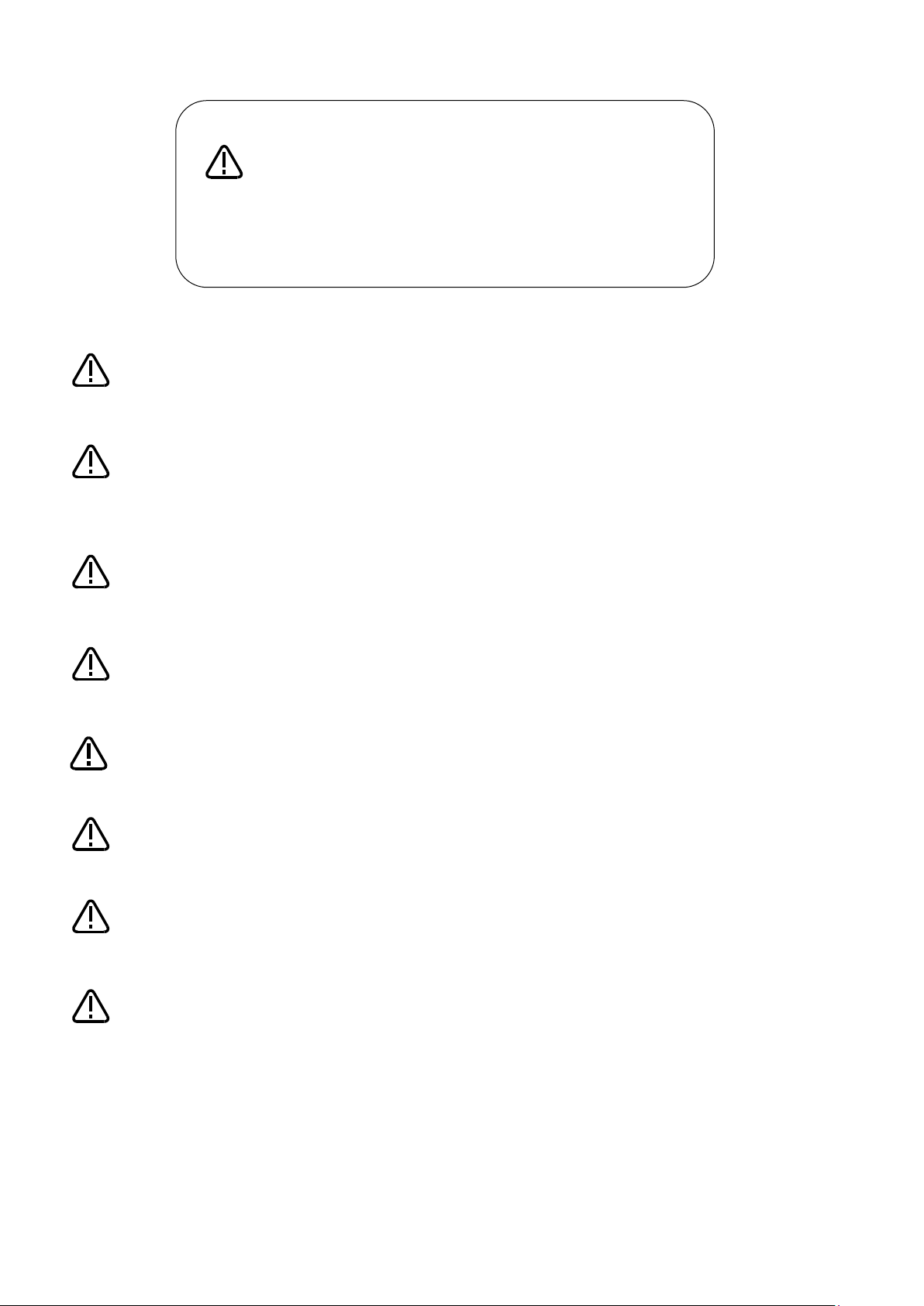
1.2. Applications
Tracking is primarily intended for applications such as the following.
(1) Transfer of processed food pallets
Figure 1
−1 Example of Processed Food Pallet Transfer
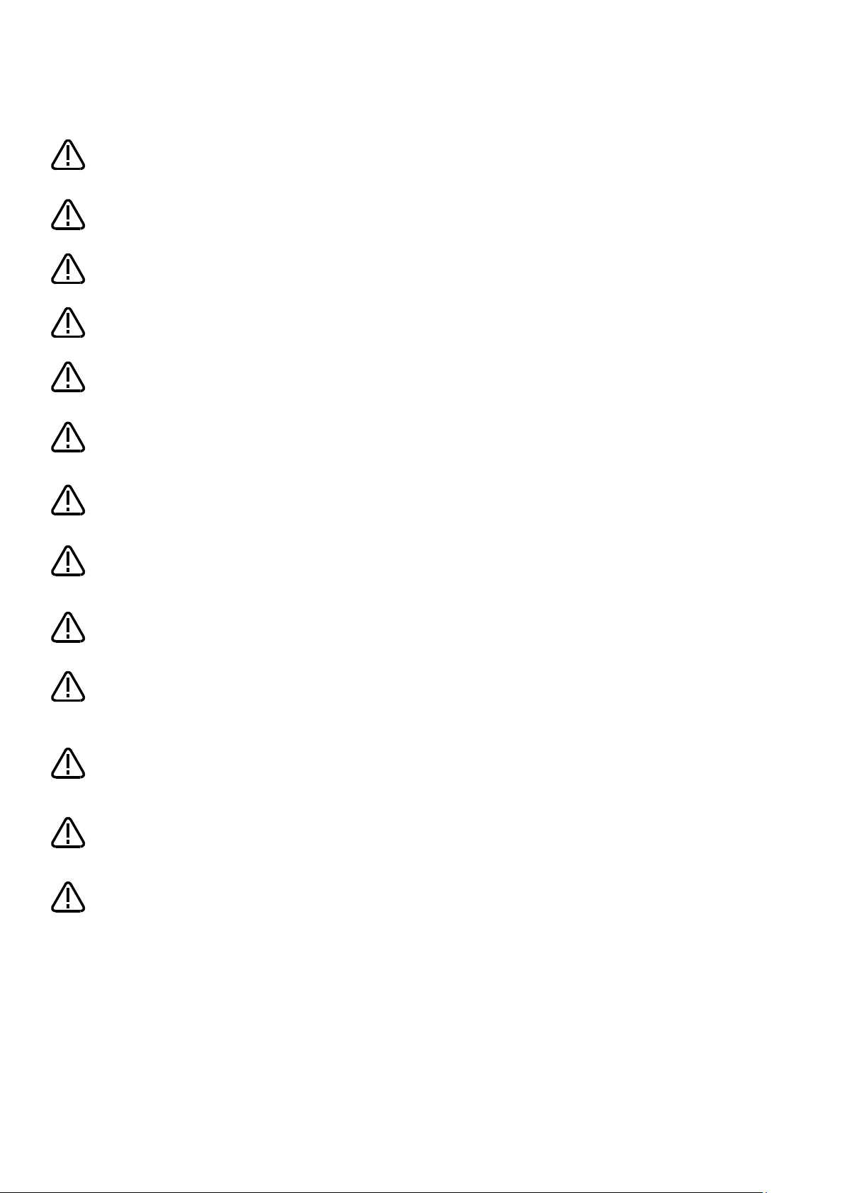
(2) Lining up parts
Figure 1
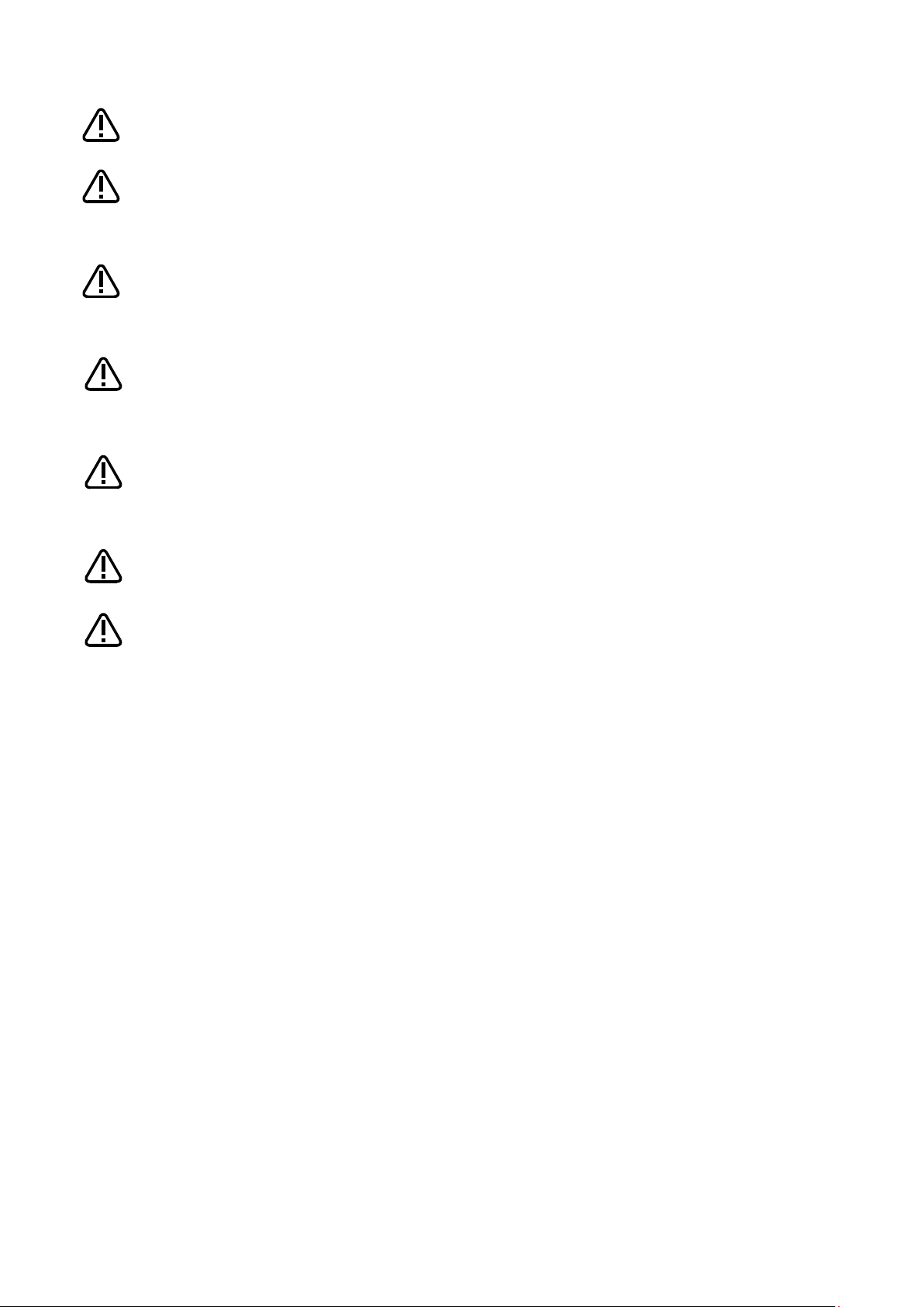
(3) Assembly of small electrical products
−2 Example of Parts Lineup
1-2 Applications
Figure 1
−3 Example of Small Electrical Products Assembly
1 Overview
Part.4 Tracking Control(12~21)
Part.2 System Configuration CR750-Q/CR751-Q/CRnQ-700 series(2~6)
Part.4 Tracking Control(12~21)
Part.3 System Configuration CR750-D/CR751-D/CRnD-700 series(7~11)
CR750-D/CR751-D/CRnD-700Series
CR750-Q/CR751-Q/CRnQ-700 series
1.3. Contents of this manual
This manual explains the operation procedure when the customer use conveyer tracking system and vision
tracking system using Mitsubishi robot. The robot model are CR750-Q/CR751-Q/CRnQ-700 series and
CR750-D/CR751-D/CRnD-700 series, however there are H/W differences. Please read as following.
System Configuration/ systemup/ Setting option parts/
Connection to encoder/ Parameter setting
Sample program/ Teaching/ Automatic operation/ Trouble shooting
System Configuration/ systemup/ Setting option parts/
Connection to encoder/ Parameter setting
Sample program/ Teaching/ Automatic operation/ Trouble shooting
Contents of this manual 1-3

1 Overview
Generic name and abbreviation
Contents
Tracking function
The tracking function allows a robot to follow workpieces moving on a
and process workpieces without having to stop the conveyer.
Conveyer tracking
The conveyer tracking allows a robot to follow workpieces lining up on
a conveyer. With this function, it becomes possible to transport,
process workpieces.
Vision tracking
The vision tracking allows a robot to follow workpieces not lining up on
and process workpieces.
Network vision sensor
The network vision sensor is an option which makes it possible to
inspect or find the workpieces by using with robot controller and
processing the image.
Q173DPX unit
Q173DRX unit is manual pulser input unit for motion controller. At Q
ncoder figure can be got by connection with 1 pc the manual
pulser machine
MR-HDP01) or 3pcs the incremental encoder.
Physical encoder number
Physical encoder numbers a number of the encoder physically
Note) The 3rd set of Q173DPX units can use only the two channels.
Logical encoder number
The physical encoder number change to the logical encoder number
number by the parameter for the encoder physically arranged. This
the instruction and the state
variable of the robot program.
TREN signal
tracking enable signal
1.4. The generic name and abbreviation
List 1-1
conveyer. With this function, it becomes possible to transport line up
a conveyer. With this function, it becomes possible to transport line up
series CPU, it is used as intelligent function unit ( occupation 32
points
Each e
generic name and abbreviation
)
(
allocated according to a certain rule.
In the CR750-Q/CR751-Q/CRnQ-700 series, the number is allocated
by arranging the encoder connected with Q173DPX unit.
The encoder which connected with CH1 of the Q173DPX unit
specified for parameter “ENC UNIT1” is the first, the encoder which
connected with CH2 is the second and with CH3 is the third.
It becomes from 4 to 6 for the Q173DPX unit specified for
parameter”ENCUNIT2”.
It becomes from 7 to 8 for the Q173DPX unit specified for
parameter”ENCUNIT3”.
by parameter “EXTENC”. The purpose of this is to change freely
logical encoder number is used with
1-4 The generic name and abbreviation

1 Overview
CR750-Q
CRnQ-700
CR750-D
CRnD-700
When a robot picks the workpieces moving on a conveyer, it is tracking.
transportation)
When a robot places workpieces which taken out from the pallet to a
workpieces on S character hook that moves the above of the robot.
A robot decorates (processing) the workpieces moving on a conveyer
while tracking.
A robot attaches the parts (assembling) with the workpieces moving on a
conveyer while tracking.
A robot has the vision sensor (hand eye) and it checks the workpieces
while tracking, not the vision sensor.
When a robot picks the workpieces moving on a conveyer A, the tracking
conveyer B.
The tracking is done with an encoder of line driver (differential motion)
output type.
The tracking is done with an encoder of voltage output/open collector
type.
In case of multi CPU system, it makes possible to add max 9 pcs
two channels can be used at the 3rd set of Q173DPX units.
1.5. System that can achieve
With the tracking function of CR750-Q/CR751-Q/CRnQ-700 series, CR750-D/CR751-D/CRnD-700 series, the
example of the system that can be achieved is shown as following.
List 1-2
Example of system that can be achieved by the tracking function
No.
CR751-Q
CR751-D
1 ● ●
2 ● ●
Example of the system
(
conveyer, it is tracking (transportation). It is also possible to hang
3 ● ●
4 ● ●
5 ● ●
6 ● ●
moving on a conveyer. (inspection) It also can check and push the button
is done and a robot places the workpieces while tracking to marking on a
7 ● ●
8 ● (●)
9 ● -
Note1)
Q173DPX units (3 units per 1 CPU). However, in each CPU, only the
Note1) This system requires the Encoder distribution unit. Please refer to the Encoder Distribution Unit
Manual (BFP-A3300) for details.
System that can achieve 1-5

2 System Configuration
Product name
Model name
Remark
Tracking Function
INSTRUCTION MANUAL
BFP-A8664
This manual is included in instruction-manual CD-ROM
attached to the product.
Sample program
−
Please refer to "12 Sample Robot Programs" for the
sample robot program.
Name of devices to be
provided by customers
Robot part
Teaching pendant
R32TB/R33TB
R56TB/R57TB
Hand
−
Hand sensor
Used to confirm that workpieces are gripped
correctly. Provide as necessary.
Solenoid valve set
Different models are used depending on the robot
necessary.
Hand input cable
Air hand interface
2A-RZ365 or
2A-RZ375
(CRnQ-700/CRnD-700 series controller)
Provide as necessary.
Calibration jig
This is a jig with a sharp tip that is attached to the
calibration tasks. It is recommended to use the jig if
high precision is required.
Encoder pulse unit
Manual pulser input unit for motion controller
robot CPU
[Part 2] System Configuration and Setting (CR750-Q/CR751-Q series,
CRnQ-700 series)
2. System Configuration
2.1. Components
2.1.1. Robot controller enclosure products
The product structure of the tracking functional relation enclosed by the robot controller is shown in the
Table 2−1.
Table 2
2.1.2. Devices Provided by Customers
When configuring the system, the customers must have certain other devices in addition to this product. The
table below shows the minimum list of required devices. Note that different devices are required depending
on whether conveyer tracking or vision tracking is used. Please refer to “Table 2−2 List of Devices Provided
by Customers (Conveyer Tracking)” and “Table 2−3 List of Devices Provided by Customers (Vision
Tracking)” for further details.
−1 List of Configuration in the tracking functional-related product
Table 2
−2 List of Devices Provided by Customers (Conveyer Tracking)
Model Quantity Remark
or
−
See the Remark
column
−
Q173DPX
1
(1)
More than
1
used. Check the robot version and provide as
mechanical interface of the robot arm and used for
[*]This unit cannot be connected with two or more
robot CPU. Please prepare for unit necessary in each
2-6 Components
2 System Configuration
Name of devices to be
provided by customers
Conveyer part
Conveyer
Encoder:
to the encoder.
Photo electronic sensor
−
Used to synchronize tracking
24V power supply
−
+24 VDC (±10%) : For the Photo electronic sensor
Encoder distribution unit
The Encoder distribution unit is required when two
(BFP-A3300) for details.
Personal computer part
Personal computer
−
Please refer to the instruction manual of RT
RT ToolBox2
support software)
Name of devices to be
provided by customers
Robot part
Teaching pendant
R32TB/R33TB
R56TB/R57TB
Hand
−
Hand sensor
Used to confirm that workpieces are gripped
correctly. Provide as necessary.
Solenoid valve set
Different models are used depending on the
as necessary.
Hand input cable
Air hand interface
2A-RZ365 or
2A-RZ375
(CRnQ-700/CRnD-700 series controller)
Provide as necessary.
Calibration jig
This is a jig with a sharp tip that is attached to the
Encoder pulse unit
More than
manual pulser input unit for motion controller
【*】
ith two or more
robot CPU. Please prepare for unit necessary in
each robot CPU.
Model Quantity Remark
(with encoder)
(Personal computer
Voltage output/open collector type
Line driver output
[Confirmed operation product]
−
1
Omron encoder (E6B2-CWZ1X-1000 or -2000)
Encoder cable (Recommended product):
2D-CBL05/2D-CBL15
[*]The Q173DPX unit supplies 5V power supply
or more manual pulser input units are connected to
2F-YZ581 (1)
the one encoder. Provide this unit as necessary.
Refer to the Encoder Distribution Unit Manual
ToolBox2 for the details of the personal computer
3D-11C-WINE
3D-12C-WINE
1
specifications.
Table 2−3 List of Devices Provided by Customers (Vision Tracking)
Model Quantity Remark
or
−
See the Remark
column
−
Q173DPX
1
robot used. Check the robot version and provide
(1)
mechanical interface of the robot arm and used
for calibration tasks. It is recommended to use
the jig if high precision is required.
1
This unit cannot be connected w
Components 2-7
2 System Configuration
Name of devices to be
provided by customers
Conveyer part
Conveyer
Encoder:
supply to the encoder.
Photo electronic sensor
−
Used to synchronize tracking
24V power supply
+24 VDC (±10%) :
sensor
Encoder distribution unit
The Encoder distribution unit is required when
Unit Manual (BFP-A3300) for details.
Vision sensor part
Basic network vision sensor
set
See the instruction manual of the network vision
sensor for details
In-Sight 5000 series
In-Sight EZ
COGNEX Vision sensor
Lens
−
C-mount lens
Lighting installation
−
(1)
Provide as necessary.
Connection part
Hub
−
1
Ethernet cable (straight)
Between Robot controller and Hub
Between Personal computer and Hub
Personal computer part
Personal computer
Please refer to the instruction manual of RT
specifications.
RT ToolBox2
(Personal computer support
software)
Please refer to the instruction manual of RT
ils of the personal computer
specifications.
Model Quantity Remark
(with encoder)
In-Sight Micro
−
−
2F-YZ581 (1)
4D-2CG5xxxx-PKG
−
1
1
Voltage output/open collector type
Line driver output
[Confirmed operation product]
Omron encoder (E6B2-CWZ1X-1000 or -2000)
Encoder cable (Recommended product):
2D-CBL05/2D-CBL15
[*]The Q173DPX unit supplies 5V power
For the Photo electronic sensor and Vision
two or more manual pulser input units are
connected to the one encoder. Provide this unit
as necessary. Refer to the Encoder Distribution
−
−
2
ToolBox2 or the instruction of the network vision
sensor for details of the personal computer
1
3D-11C-WINE
3D-12C-WINE
ToolBox2 for the deta
2-8 Components
2 System Configuration
Robot movement range
Workpieces
DU
R
Encoder
(Detected the speed
of the convetor)
(Detected the inflow
of the work)
Photoelectric sensor
Robot
Controler
Q173DPX
Robot CPU
Workpieces
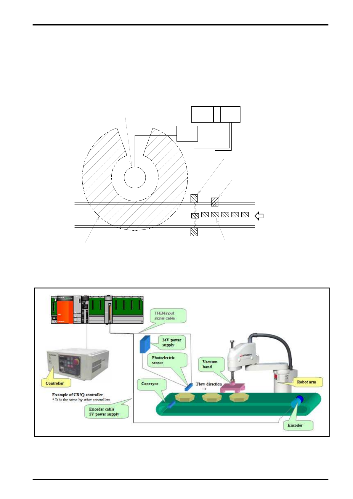
2.2. Example of System Configuration
The following figure shows examples of conveyer tracking systems and vision tracking systems.
2.2.1. Configuration Example of Conveyer Tracking Systems
The following figure shows a configuration example of a system that recognizes lined-up workpieces on a
conveyer passing a photo electronic sensor and follows the workpieces.
flow direction
Figure 2
−1 Configuration Example of Conveyer Tracking (Top View)
Figure 2
−2 Configuration Example of Conveyer Tracking
Example of System Configuration 2-9
2 System Configuration
Robot movement range
Workpieces
DU
R
Encoder
(Detected the speed
(Recognized the work
Robot
Controler
Q173DPX
Robot CPU
Camera for vision sensors
Workpieces
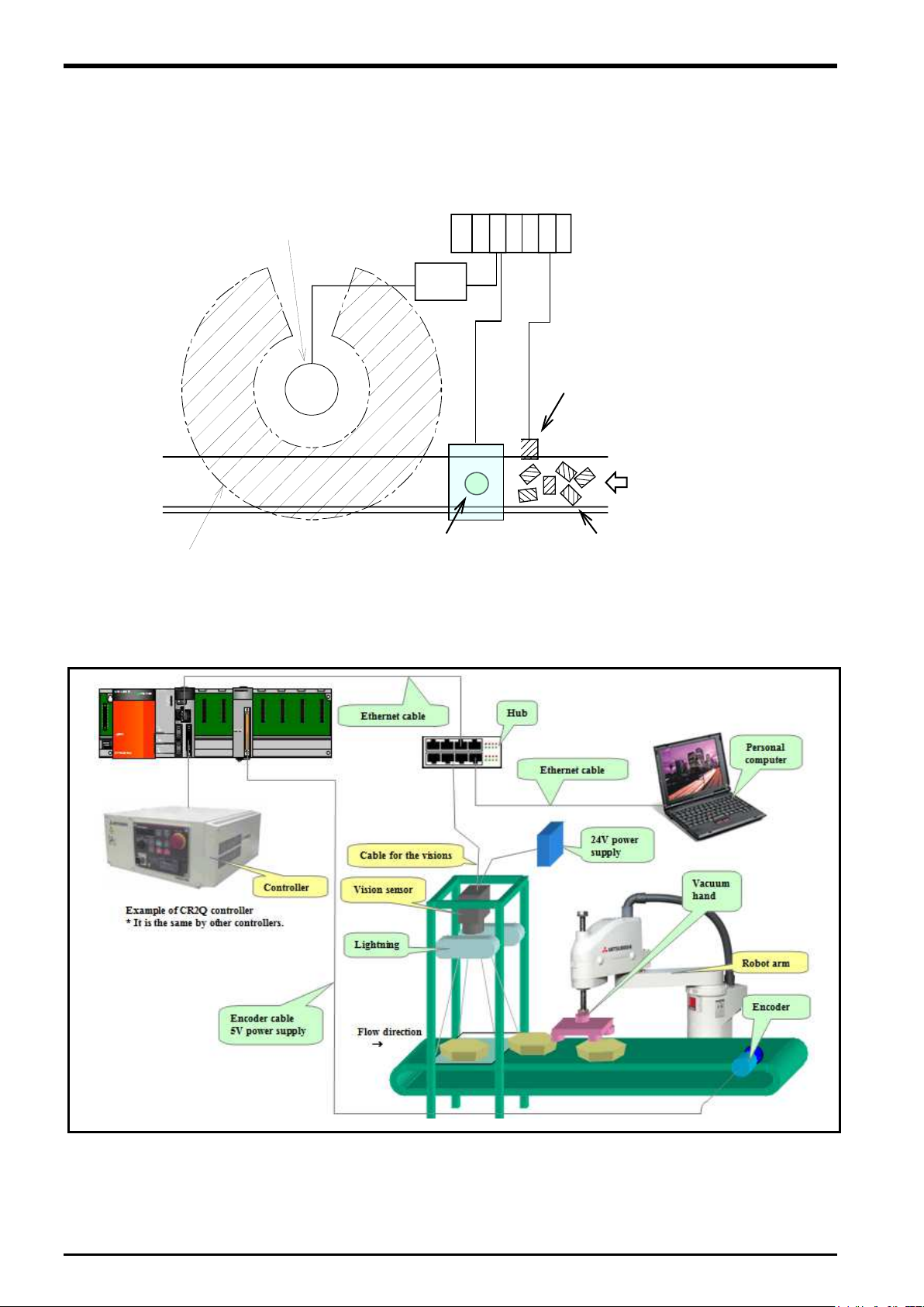
2.2.2. Configuration Example of Vision Tracking Systems
The following figure shows a configuration example of a system that recognizes positions of workpieces that
are not lined up on a conveyer with a vision sensor and follows the workpieces.
of the convetor)
flow direction
of the position and inclination)
Figure 2
−3 Configuration Example of Vision Tracking (Top View)
2-10 Example of System Configuration
Figure 2
−4 Configuration Example of Vision Tracking
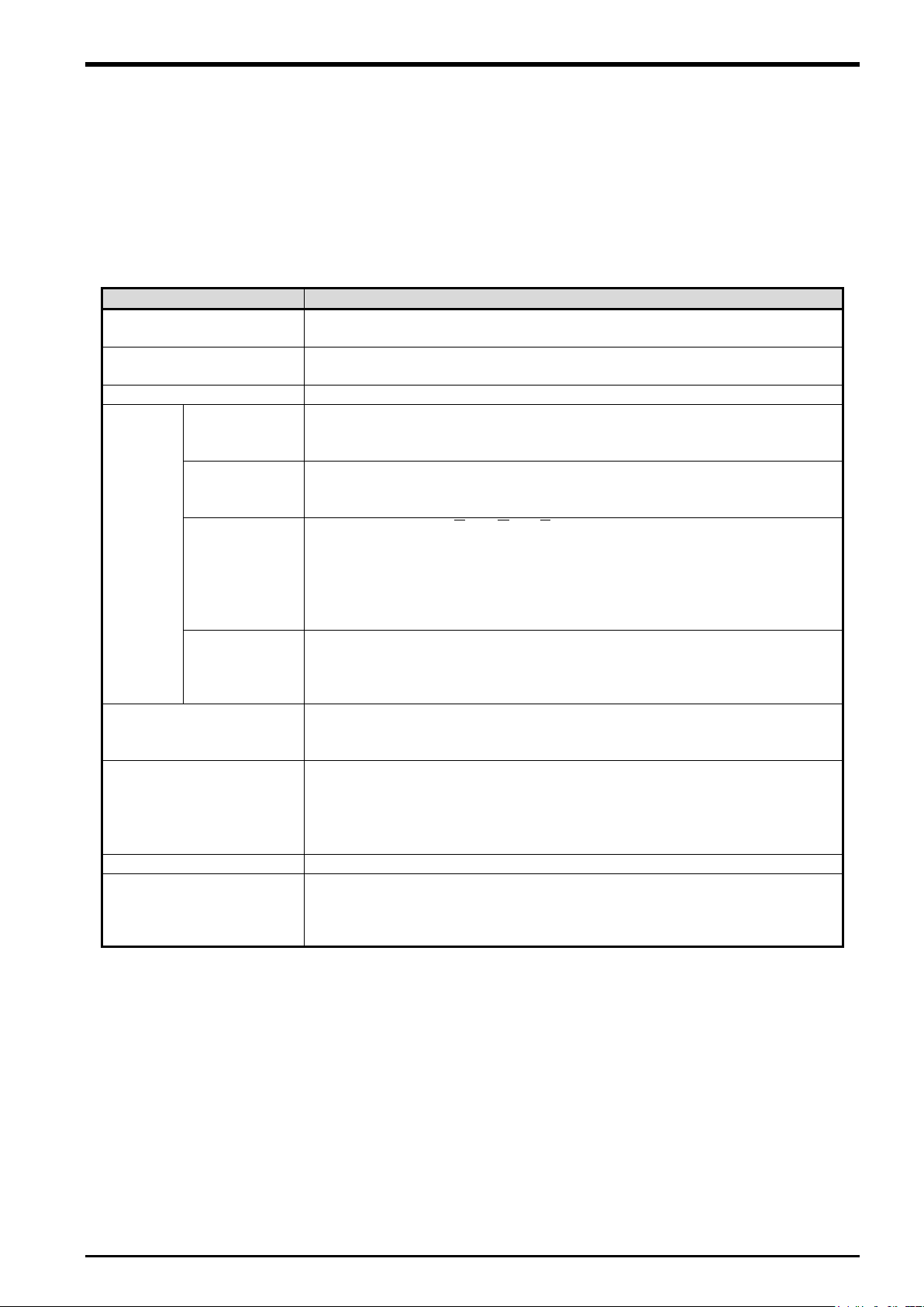
3 Specification
Item
Specification and Restriction matter
Supported robots (*8)
RH-SQH series / RV-SQ series
RH-FH-Q series / RV-F-Q series
Applicable robot controller
CR1Q / CR2Q / CR3Q controller
CR750-Q/CR751-Q series controller
Robot program language
Load commands dedicated for the tracking function
Conveyer
Number of
(*6)
Max 8pcs
in case 1pc encoder connect to 1 pc conveyer)
Q173DPX unit 3pcs / system
Movement
Possible to support up to 300mm/s (When the robot always transport the
Possible to support up to 500mm/s when the interval of workpiece is wide.
Encoder
Output aspect :
ZZBBAA 、、、、、
E6B2-CWZ1X-2000
Encoder cable
Option:
Conductor size: AWG#28
Encoder unit
Only Q173DPX unit
One Q173DPX is necessary for each robot CPU.
Photoelectronic sensor
Used to detect workpieces positions in conveyer tracking.
variable "M_EncL".
Vision sensor(*4)
Mitsubishi’s network vision sensor
Precision at handling
Approximately ±2 mm (when the conveyer speed is approximately 300
(Photoelectronic sensor recognition accuracy, vision sensor recognition
accuracy, robot repeatability accuracy and so on)
3. Specification
3.1. Tracking Specifications and Restriction matter
”Table 3−1 CR750-Q/CR751-Q Series, CRnQ-700 Series Controller Tracking Function Specifications”
shows the tracking specifications.
Please refer to “Standard Specifications Manual” for the specifications of the robot arm and controller to be
used.
Table 3−1 CR750-Q/CR751-Q Series, CRnQ-700 Series Controller Tracking Function Specifications
(
conveyer
Encoder 3 pcs / Q173DPX unit 1pc
Speed (*1)
position (*5)
(*3)
workpieces)
Output form : Voltage output/open collector type (*7)
Line driver output (*2)
Resolution(pulse/rotation)) : Up to 2000 (4000 and 8000 uncorrespond))
Confirmed operation product : Omuron E6B2-CWZ1X-1000
2D-CBL05(External I/O cable 5m)
2D-CBL15(External I/O cable 15m)
[*] Two or more robots CPU cannot share one Q173DPX.
Output signal of sensor need to be connected to TREN terminal of
Q173DPX unit. (Input signal number 810~817)
And a momentary encoder value that the input enters is preserved in state
mm/s)
(*1) The specification values in the table should only be considered guidelines. The actual values
depend on the specific operation environment, robot model, hand and other factors.
(*2) The line driver output is a data transmission circuit in accordance with RS-422A. It enables the
long-distance transmission.
(*3) Please connect the output signal of a photoelectric sensor with the terminal TREN of the Q173DPX
unit. This input can be confirmed,by the input signal 810th-817th.
(*4) In the case of vision tracking, please refer to the instruction manual of network vision sensor.
(*5) The precision with which workpieces can be grabbed is different from the repeatability at normal
transportation due to the conveyer speed, sensor sensitivity, vision sensor recognition accuracy and
other factors. The value above should only be used as a guideline.
(*6) The encoder connected with the third channel of the Q173DPX unit specified for parameter
"ENCUNIT3" cannot be used.
(*7) Voltage output/open collector type is an output circuit with two output transistors of NPN and PNP.
(*8) The sample program doesn't correspond to the RV-5 axis robot.
Tracking Specifications and Restriction matter 3-11

4 Operation Procedure
4. Sample Robot Programs ······································································ Refer to “Chapter 12.”
5. Calibration of Conveyer and Robot Coordinate Systems (“A1” program) ········ Refer to “Chapter 13.”
7. Workpiece Recognition and Teaching (“C1” program) ································ Refer to “Chapter 15.”
explains how to calculate the relationship between the position of a workpiece
9. Automatic Operation ··········································································· Refer to “Chapter 18.”
10. Maintenance ····················································································· Refer to “Chapter 19.”
11. Troubleshooting ··············································································· Refer to “Chapter 20.”
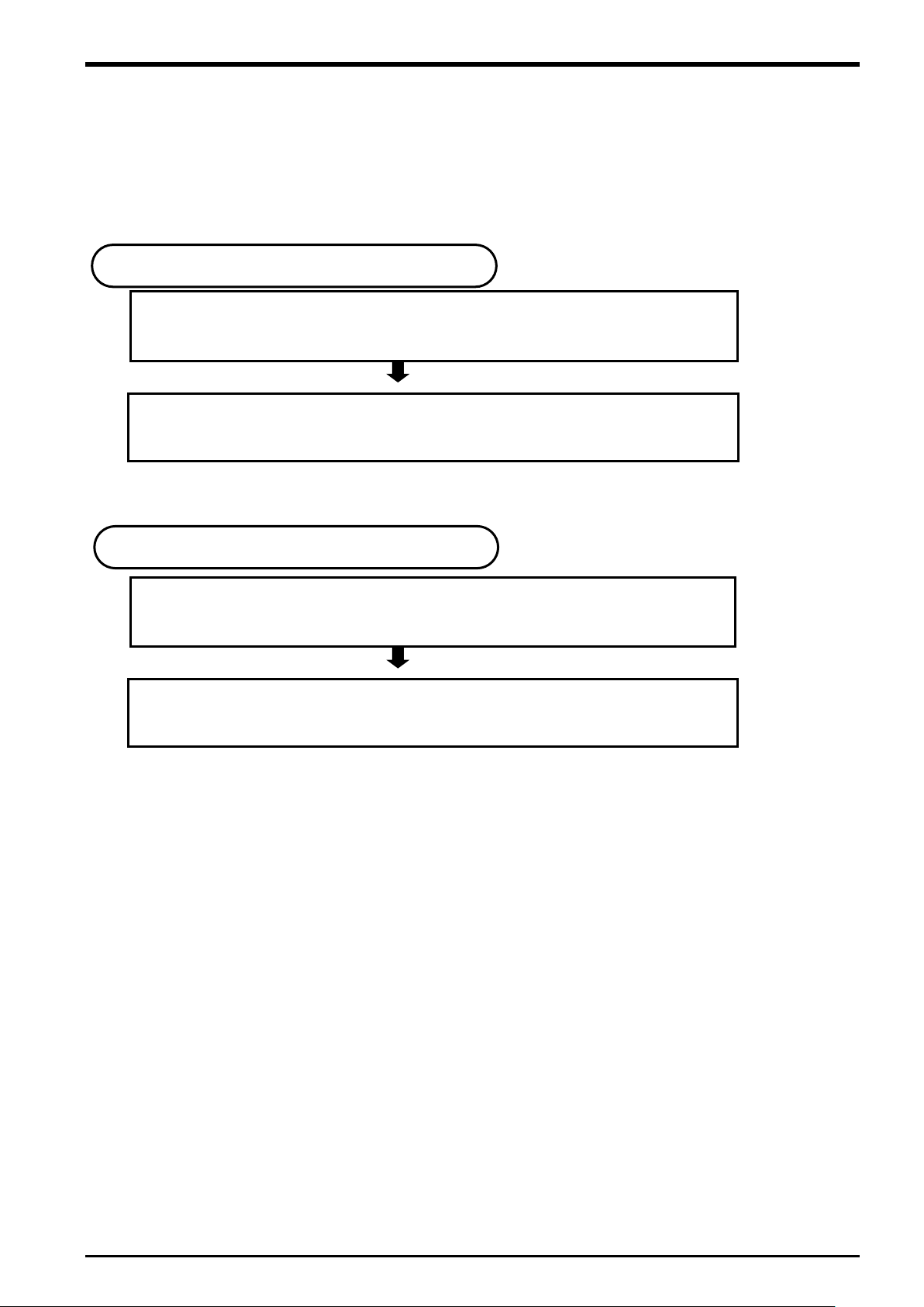
3. Parameter Setting ················································································ Refer to “Chapter 6.”
1. Start of operation
End of operation
2. Connection of Equipment ······································································· Refer to “Chapter 5.”
8. Teaching and Setting of Adjustment Variables (“1” Program) ······················· Refer to “Chapter 16.”
6.
Calibration of Vision Coordinate and Robot Coordinate Systems (“B1” program)
··· Refer to “Chapter 14.”
4. Operation Procedure
This chapter explains the operation procedure for constructing a conveyer tracking system and a vision
tracking system using Mitsubishi Electric industrial robots CR750-Q/CR751-Q series, CRnQ-700 series.
It explains Q173DPX (manual pulser input) unit preparation and the connection with the encoder.
Chapter 6 explains assignment of signals and setting of parameters related to tracking to allow an
external device to control a robot.
Chapter 12 explains functions related to supplemental sample programs.
Chapter 13 explains how to calculate the amount of robot movement per encoder pulse.
Chapter 14 explains how to display the position of a workpiece recognized by the vision sensor in
the robot coordinate system.
Chapter 15
recognized by the vision sensor and the position at which the robot grabs the workpiece.
Chapter 16 explains how to make settings such that the robot can follow workpieces moving by on a
conveyer and how to teach the robot origin and transportation destination at system start-up.
In automatic operation, the robot operates via commands from the conveyer control.
4-12 Tracking Specifications and Restriction matter

5 Connection of Equipment
5. Connection of Equipment
This section explains how to connect each of the prepared pieces of equipment.
5.1. Preparation of Equipment
Prepare equipment by referring to “Table 2−2 List of Devices Provided by Customers (Conveyer Tracking)”
to construct a conveyer tracking system and “Table 2−3 List of Devices Provided by Customers (Vision
Tracking)” to construct a vision tracking system.
Preparation of Equipment 5-13
5 Connection of Equipment
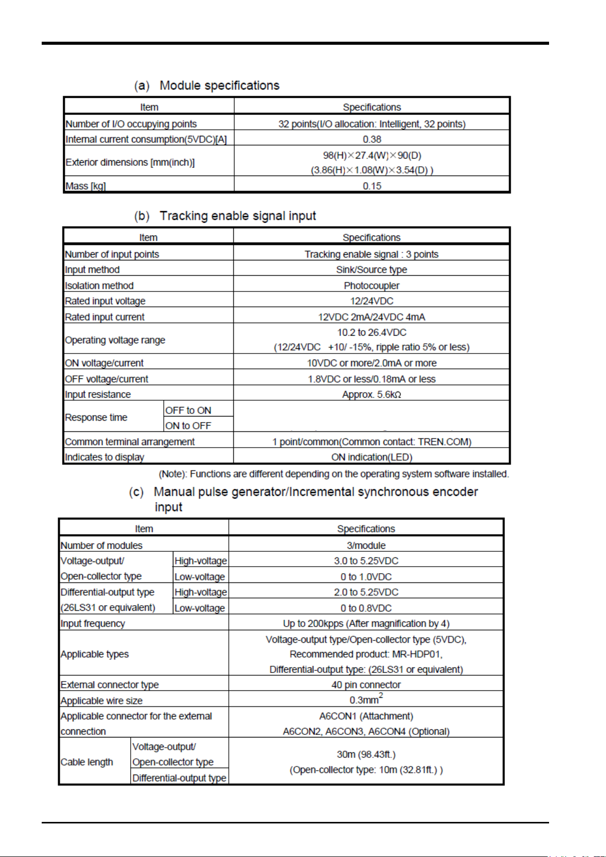
5.1.1.
Q173DPX(
manual pilser input) unit specification
Add Q173DPX unit into PLC base unit (Q3□DB ) when the customer use CR750-Q/CR751-Q series,
CRnQ-700 series tracking function. Please refer to
"Q173DCPU/Q172DCPU user's manual" about details of this unit.
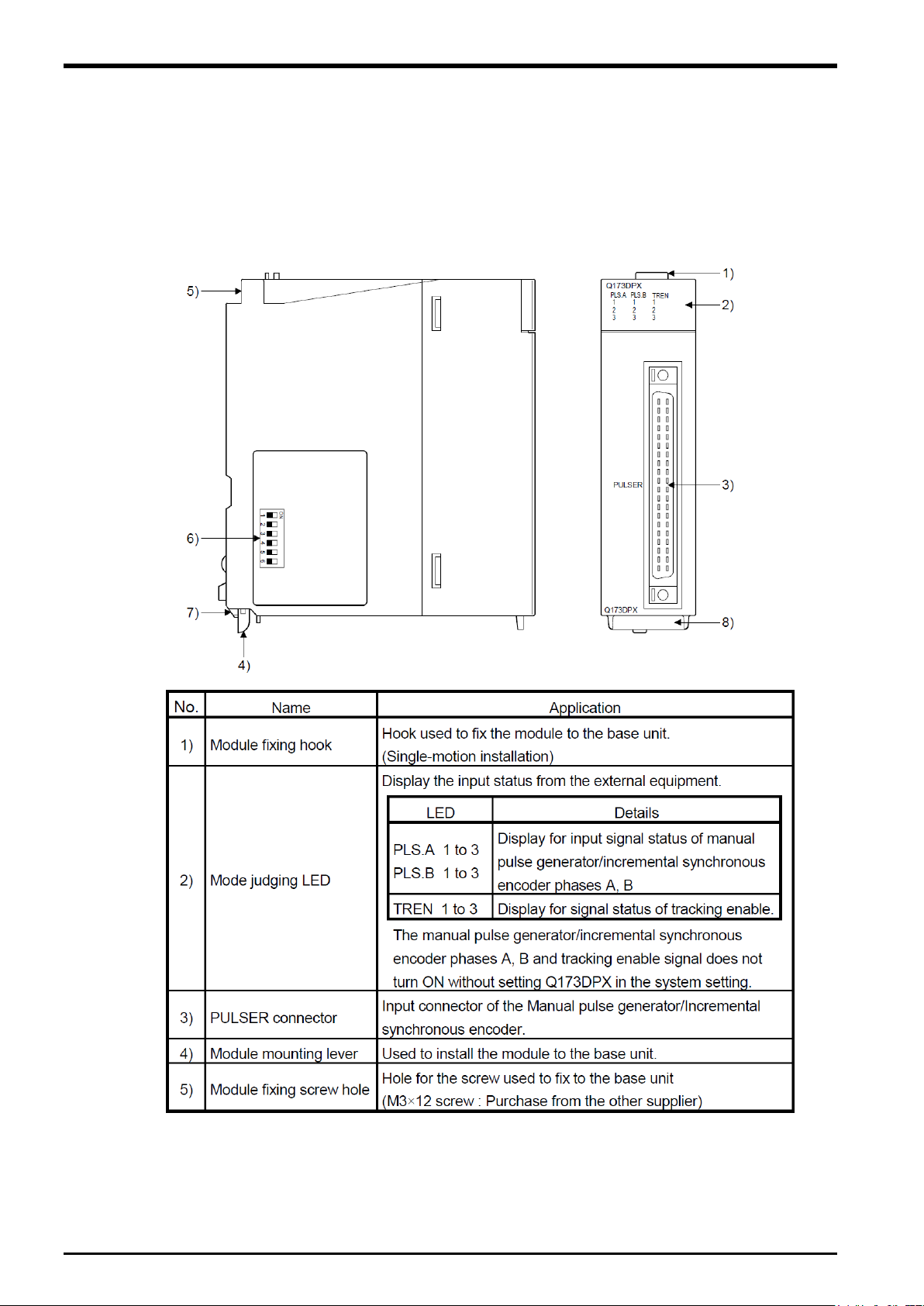
(1) External and name of Q173DPX unit
Figure 5
−1 Externals of Q173DPX unit
5-14 Preparation of Equipment
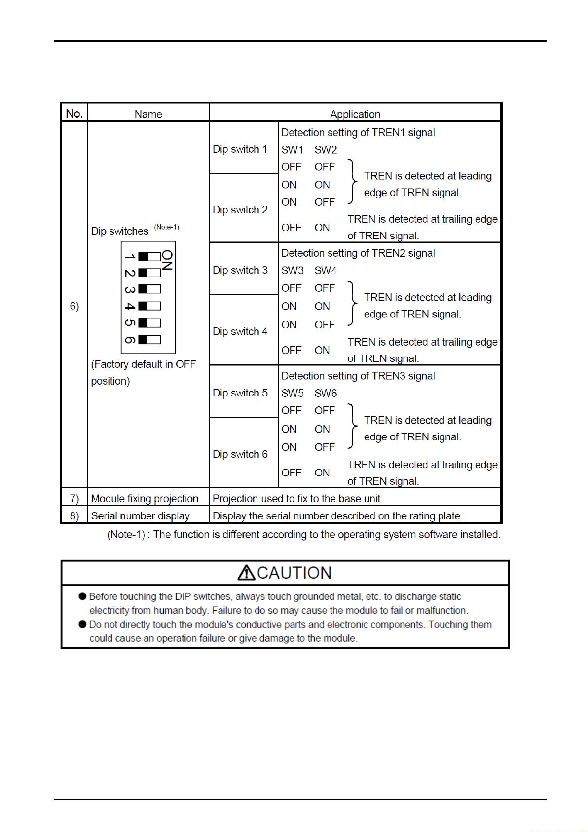
(2) Dip switch
By setting the dip switch, the condition of the tracking enable signal is decided.
List 5-1
Item of dip switch
5 Connection of Equipment
Preparation of Equipment 5-15
5 Connection of Equipment
7.1ms
(3) Specification of hardware
5-16 Preparation of Equipment
5 Connection of Equipment
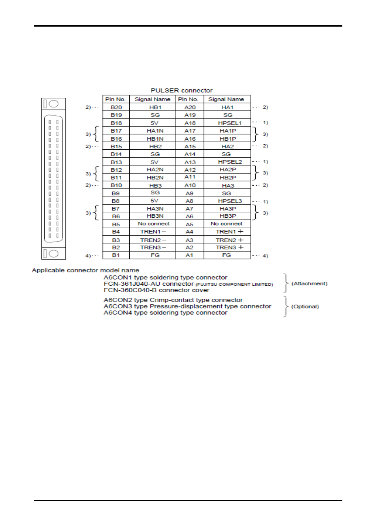
(4) Wiring
The pin layout of the Q173DPX PULSER connecter viewed from the unit is shown below.
Figure 5
−2 Pin assignment of the PULSER connector
Preparation of Equipment 5-17
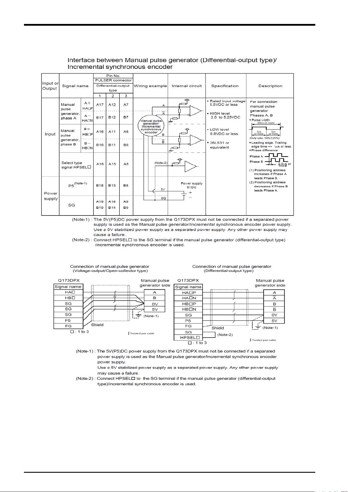
5 Connection of Equipment
Interface between PULSER connecter and manual pulse generator (Differential-output type)/ Incremental
synchoronous encoder
Figure 5
−3 Wiring connection with rotary encoder
As above image, because DC5V voltage is output from Q173DPX unit, it makes possible to supply 5V from
Q173DPX unit to rotary encoder. When 24V encoder type of power supply is used, it makes possible to use
24V output from PLC power unit.
5-18 Preparation of Equipment
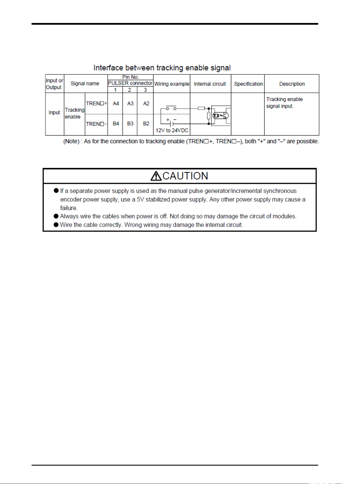
The interface between tracking enable signal is shown follow.
This signal is used for input signal when the
connect output signal of
photoelectronic sensor.
photoelectronic sensor is used to find workpieces so please
5 Connection of Equipment
Figure 5
−4 Connected composition of tracking enable signal
Preparation of Equipment 5-19
5 Connection of Equipment
Item
Spec and Remark
Encoder
Incremental synchronous encoder 3pcs
Tracking input points
3points
When the input of a photoelectric sensor is put, this input is used.
Slot that can be connected
Connection with the base unit Possible to install I/O slot since 3
Connection with additional base unit Possible to install all slots.
Robot CPU unit that can be
managed
Q173DPX unit 3pcs
Robot CPU encoder that
Max 8pcs
unit specified for parameter「ENCUNIT3」.
5.2. Connection of Equipment
The connection with each equipments is explained as follow.
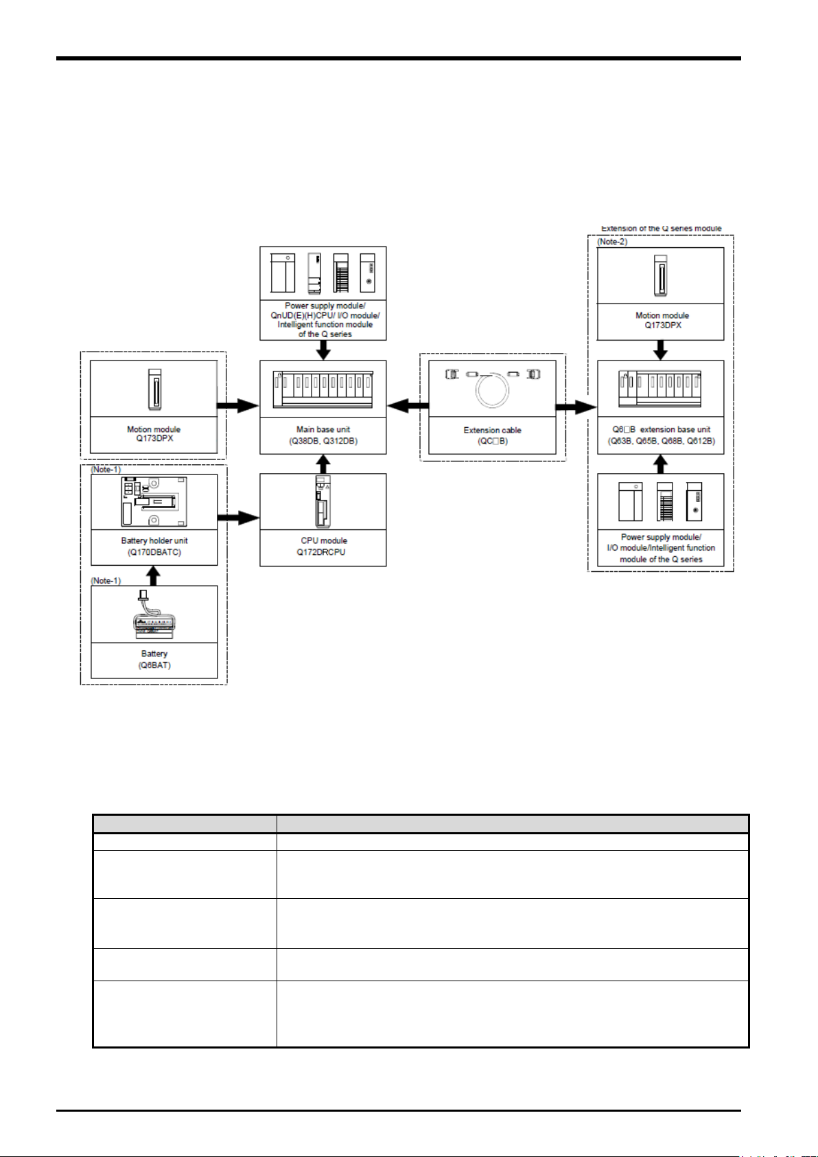
5.2.1. Connection of Unit
Q173DPX unit is connected to base unit (Q3□DB) or Q6□B increase base unit.
Figure 5
−5 Connected composition of units
The connection robot system with Q173DPX unit is shown as follow.
List 5-2 Spec list of Q173DPX in robot system
Three points can be input to ± TREN1-3 in the pin assignment of the unit.
(Impossible to install CPU slot or I/O slot 0 to 2)
can be managed
Impossible to use the third channel of the third Q173DPX unit.
And impossible to use the encoder connected with the third channel of the
5-20 Connection of Equipment
 Loading...