

Page 1

CLUTCH
21-1
CONTENTS
GENERAL INFORMATION 2..................
SERVICE SPECIFICATIONS 2.................
LUBRICANTS 2..............................
ON-VEHICLE SERVICE 2.....................
Clutch Pedal Inspection and Adjustment 2.......
Bleeding 3.....................................
21109000190
CLUTCH PEDAL 4...........................
CLUTCH CONTROL 5........................
Clutch Master Cylinder 7.......................
Page 2
21-2
CLUTCH -
General Information/Service Specifications/Lubricants/On-vehicle Service
GENERAL INFORMATION
The clutch is a dry single-disc, diaphragm type;
hydraulic pressure is used for the clutch control.
SERVICE SPECIFICATIONS
Items Standard value
Clutch pedal height mm 224 - 227 <L.H. drive vehicles>
211 - 214 <R.H. drive vehicles>
Clutch pedal clevis pin play mm 1-3
Clutch pedal free play mm 6-13
Distance between the clutch pedal and the toeboard
when the clutch is disengaged mm
125 or more
LUBRICANTS
Items Specified lubricants Quantity
Clutch fluid Brake fluid DOT3 or DOT4 As required
Push rod assembly Rubber grease
Boot
21100010093
21100030150
21100040078
Release cylinder push rod MITSUBISHI genuine grease
Part No. 0101011
Clutch pedal height Clutch pedal clevis
pin play
ON-VEHICLE SERVICE
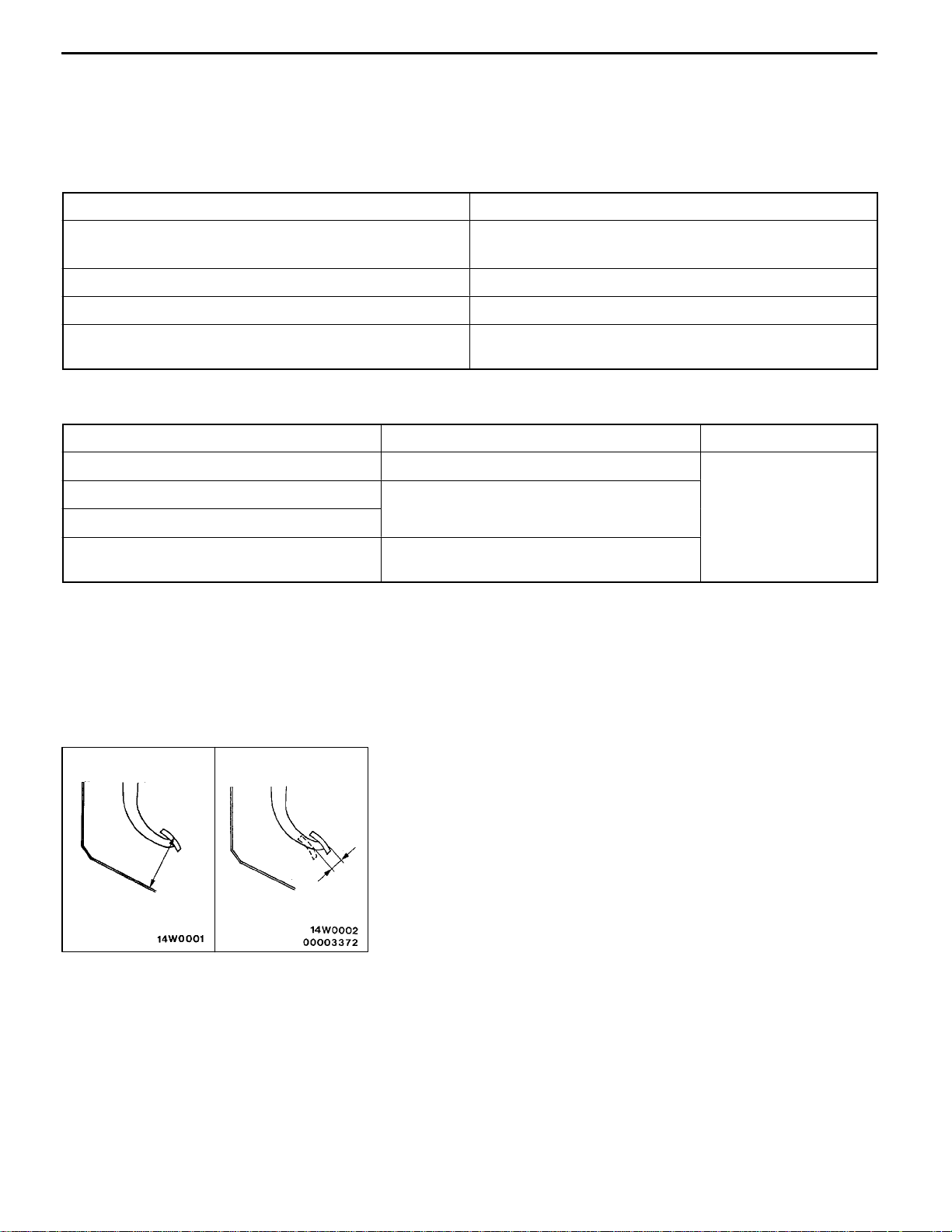
CLUTCH PEDAL INSPECTION AND
ADJUSTMENT
1. Turn up the carpet, etc. under the clutch pedal.
A
B
2. Measure the clutch pedal height and the clutch pedal
clevis pin play.
Standard value (A):
224 - 227 <L.H. drive vehicles>
211 - 214 <R.H. drive vehicles>
Standard value (B): 1 - 3 mm
21100090158
Page 3
Setting nut
12 Nm
CLUTCH -
Clutch pedal
On-vehicle Service
21-3
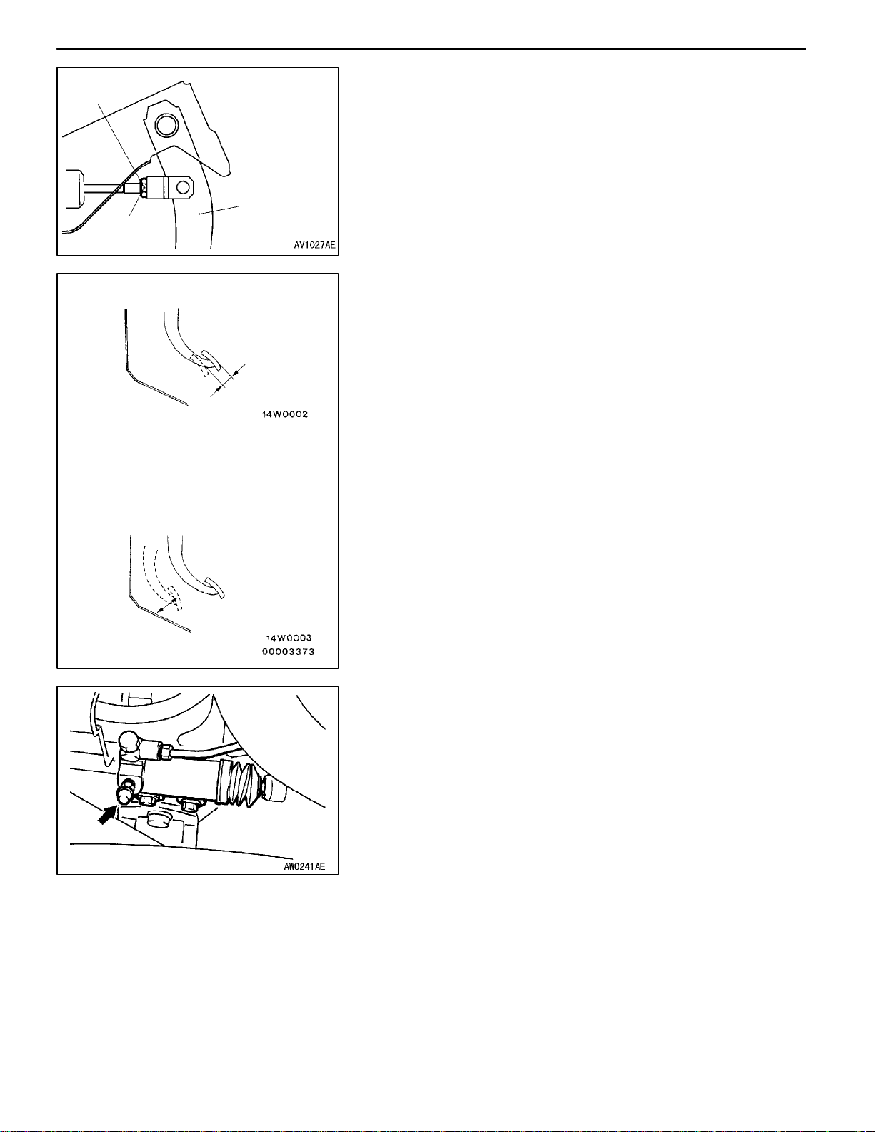
3. If the clutch pedal height and the clutch pedal clevis pin
play are outside the standard value, turn the setting nut
to adjust them to the standard value.
Caution
Do not push in the master cylinder push rod at this
time, otherwise the clutch will not operate properly.
Clutch pedal free play
C
Distance between the clutch pedal and the
toeboard when the clutch is disengaged
D
4. After completing the adjustments, confirm that the clutch
pedal free play (measured at the face of the pedal pad)
and the distance between the clutch pedal (the face of
the pedal pad) and the toeboard when the clutch is
disengaged are within the standard value ranges.
Standard value (C): 6 - 13 mm
Standard value (D): 125 mm or more
5. If the clutch pedal free play and the distance between
the clutch pedal and the toeboard when the clutch is
disengaged do not agree with the standard values, it
is probably the result of either air in the hydraulic system
or a faulty master cylinder or clutch. Bleed the air, or
disassemble and inspect the master cylinder or clutch.
6. Turn back the carpet, etc.
BLEEDING
21100140143
Specified fluid: Brake fluid DOT 3 or DOT 4
Caution
Use the specified brake fluid. Avoid using a mixture of
the specified fluid and other fluid.
Page 4

21-4
CLUTCH -
Clutch Pedal
CLUTCH PEDAL
REMOVAL AND INSTALLATION
Post-installation Operation
Clutch Pedal Adjustment (Refer to P.21-2)
7
12 Nm
21100160224
5
Removal steps
1. Clutch switch
2. Clip
3. Snap pin
4. Bushing
5. Pin assembly
2
1
4
10
6
12 Nm
3
8
9
6. Clutch master cylinder mounting nut
7. Master cylinder member mounting bolt
8. Clutch pedal
9. Stopper <R.H. drive vehicles>
10. Pedal pad
Page 5

CLUTCH -
Clutch Control
21-5
CLUTCH CONTROL
REMOVAL AND INSTALLATION
Pre-removal Operation
Clutch Fluid Draining
<L.H. drive vehicles>
5
7
21100190216
Post-installation Operation
D Clutch Fluid Supplying
D Clutch Line Bleeding (Refer to P.21-3)
D Clutch Pedal Adjustment (Refer to P.21-2)
3
1
4
9
12 Nm
6
19 Nm
15 Nm
7, 8
8
12 Nm
Release
cylinder
push rod
Specified grease:
MITSUBISHI genuine
grease Part No. 0101011
8
Release
fork
2
29 Nm
Clutch master cylinder removal
steps
1. Clevis pin assembly
2. Clutch pipe connection
3. Reservoir hose
4. Clutch master cylinder
Clutch release cylinder removal
steps
5. Clutch pipe connection
6. Clutch release cylinder
Clutch line removal steps
7. Clutch pipe
8. Clutch hose
9. Bracket
10. Clutch hose
Page 6

21-6
<R.H. drive vehicles>
CLUTCH -
Clutch Control
3
1
4
19 Nm
5
7
2
9
12 Nm
7
6
8
12 Nm
Release
cylinder
push rod
15 Nm
Release fork
8
Clutch master cylinder removal
steps
1. Clevis pin assembly
2. Clutch pipe connection
3. Reservoir hose
4. Clutch master cylinder
Specified grease:
MITSUBISHI genuine
grease Part No. 0101011
Clutch release cylinder removal
steps
5. Clutch pipe connection
6. Clutch release cylinder
Clutch line removal steps
7. Clutch pipe
8. Bracket
9. Clutch hose
Page 7

CLUTCH -
Clutch Control
21-7
DISASSEMBLY AND REASSEMBLY
CLUTCH MASTER CYLINDER
Caution
Do not disassemble piston assembly.
<L.H. drive vehicles>
6
5
9
<R.H. drive vehicles>
6
5
21100210172
12 Nm
2
3
1
4
12 Nm
2
9
8
44 Nm
1
2
Piston repair kit
Disassembly steps
1. Piston stopper ring
2. Piston assembly
"AA 3. Push rod assembly
4. Boot
5. Spring pin
3
4
1
7
4
2
2
3
Clutch fluid:
Brake fluid DOT3 or DOT4
Grease: Rubber grease
6. Nipple
7. Gasket
8. Damper assembly
9. Master cylinder body
Page 8

21-8
<L.H. drive vehicles> 103 mm
<R.H. drive vehicles> 121 mm
CLUTCH -
INSTALLATION SERVICE POINT
"AA
Set the length of the push rod assembly to the shown
dimension to make the adjustment of clutch pedal easier.
Clutch Control
PUSH ROD ASSEMBLY INSTALLATION
 Loading...