

Mitsubishi Electric CL1XY2-DT1D5S User Manual
Side
0
X0 input operation
indicator LED
Y0 output operation
indicator LED
0
Crimp-style connection device with
insulator or closed end connection
device
Sensor,
switch, etc.
Crimp-style connection device with
insulator or closed end connection
device
Lamp,
solenoid, etc.
Input
equipment
Connector dedicated to CC-Link/LT
Output
equipment
Wire diameter: AWG18 (34/0.18)
30mm(1.19") 30mm(1.19")
1)Fit the remote
I/O module in
a corner of the
CL1-HLD.
2)Press down b)
while holding
a).
1)Insert a screwdriver into either a, b, c, or d.
2)Pry the remote I/O module from the
holder using the screwdriver.
Mount Dismount
CL1-HLD
Remote
I/O
module
a)
b)
a
b
c
d
A
Side
B
CL1XY2-DT1D5S
CC-Link/LT Remote I/O Module
Please read this manual thoroughly before star ting to use the product and
handle the product properly.
User’s Manual
MODEL CL1XY2-DT1D5S
MANUAL Number JY997D03801K
Date August 2017
SAFETY PRECAUTIONS
●
Please read this m anual carefully an d pay special attentio n to safety in order
to handle this product p roperly. Also pay careful attention to sa fety and handle
the module properly.
These precautions apply onl y to Mitsubishi equipment. Refer to th e user’s
manual of the CPU mo dule to use for a descr iption of the PLC system safety
precautions.
These
categories: "WARNING" and "CAUTION".
Depending on circumstan ces, procedures indicated by may also
be linked to s erious re sults.
In any case, it is important to follow the directions for usage.
Store this manual in a safe place so that you can take it out and read it
whenever necessary. Always forward it to the end user.
[DESIGN PRECAUTIO NS]
• Configure an interlock circuit in a sequence program so that the system operates on the safety
side using the communication status information in the event the data link falls into a
communication problem.
Otherwise, erroneous output and malfunction may result in accidents.
• Remote input and output can not be switched ON or OFF when a problem occurs in the remote
I/O modules. Therefore build an external monitoring circuit that will monitor any input signals that
could cause a serious accident.
• Do not have control cables and connection cables bundled with or placed near by the main
circuit and/or power cables. Wire those cables at least 100mm(3.94 inch) away from the main
circuit and/or power cables. It may cause malfunction due to noise interference.
• Use the module in the status in which any force is not applied on the module, flat cables
dedicated to CC-Link/LT and flat cables for I/O.
If a force is applied, wire breakage or failure may be caused.
(Read these precautions before using. )
●
SAFETY PRECAUTIONS● classify the safety precautions into two
Procedures which may lead to a dangerous c ondition
and cause death or serious injur y if not carried out
properly.
Procedures which may lead to a dangerous c ondition
and cause superficial to medium injur y, or physical
damage only, if not carried out properly.
[INSTALLATION PRECAUTIONS]
• Use the module in an environment that meets the general specifications contained in this
manual. Using this module in an environment outside the range of the general specifications
could result in electric shock, fire, erroneous operation, and damage to or deterioration of the
product.
• Do not directly touch the module's conductive parts. Doing so could cause malfunction or trouble
in the module.
[WIRING PRE CAUTIONS]
• Perform installation and wiring after disconnecting the power supply at all phases externally. If
the power is not disconnected at all phases an electric shock or product damage may result.
• Perform correct wiring for the module according to the product's rated voltage and terminal
arrangement. Connecting to a power supply different from rating or miss-wiring may cause fire,
product failure or malfunction.
• Make sure foreign objects do not get inside the module, such as dirt and wire chips. It may cause
fire, product failure or malfunction.
• Do not short-circuit the 24G and +24V terminals. It may result in fire, product failure or
malfunction.
• Attach a warning label (hazard symbol 417-IEC-5036) concerning the electric shock to the
location.
●
JAPANESE
ENGLISH
Side
B
[STARTING AND MAINTENANCE PRECAUTIONS]
• Do not touch the terminals when the power is ON. It may cause an electric shock or malfunction.
• Perform cleaning the module after turning OFF the all external power supply for sure. Failure to do so
may cause failure or malfunction of the modules.
• Do not disassemble or modify the module. Doing so may cause failure, malfunction, injury, or fire.
• The module case is made of resin; do not drop it or subject it to strong shock. A module damage may
result.
• Make sure to switch all phases of the external power supply OFF before installing or removing the
module to/from the panel. Failure to do so may cause failure or malfunction of the modules.
[DISPOSAL PR ECAUTIONS]
• When disposing of this product, treat it as industrial waste.
[TRANSPORTATION AND MA INTENANCE PRECAUTIONS]
• During transportation avoid any impact as the module is a precision instrument. Doing so could cause
trouble in the module.
• If is necessary to check the operation of module after transportation, in case of any impact damage.
Notification of CE marking
This notification does not guarantee that an entire mechanical mo dule produced
in accordance with the contents of the notification comply with the following
standards. C ompliance to EMC stand ards of the e ntire mechan ical modu le
should be checked by the user / ma nufacturer.
Attention
This product is designe d for use in industrial a pplications.
Standards with which this product complies
Type : Programmable Controller (Ope n Type Equipment) Remote I/O module
Models : Products manufactured:
from November 1st, 2002 to Ap ril 30th, 2006 are compliant with
EN61000-6-4 and E N61131-2:1994+A11 :1996+A12:2000
after May 1st, 2006 are compl iant with EN61131-2:200 7
Electromagnetic Compat ibility
EN61000-6-4:2001
Electromagnetic compatibility
-Generic standards - Emiss ion standard
for Industrial environment
EN61131-2:1994/A11 :1996/A12:2000
Programmable controllers
-Equipment requirements and tests
EN61131-2: 2007
Programmable controllers
-Equipment requirements and tests
For more details please conta ct the local Mitsubishi E lectric sales site.
• Note s for compliance to EMC regulati on.
It is necessary to install the CL1 series module in a shielded metal control
panel.
• Use thi s product in Zone A
*1 Zone defined in EN6113 1-2
Separation defined in EN61131-2 for EMC LVD regulation decided
depending on condition in industrial setting.
Zone C = Factory mains which is isolated from public mains by dedicated
Zone B = Dedicated power distr ibution which is protected by seco ndary
Zone A = Local power distribution which is isolated from dedicated power
●
Standards (EMC)
*1
transformers.
surge protection. (300 V or less in the rated voltage is
assumed.)
distribution by AC/DC converters, isolation tran sformers, etc.
(120 V or less in the rated voltage is assumed.)
Compliance with all relevant aspects of
the standard.
(Radiated Emissions and Mains
Terminal Voltage Emissions)
Compliance with all relevant aspects of
the standard.
• Radiated electromagnetic field
• Fast transient burst
• Electrostatic discharge
• Damped oscillatory wave
Compliance with all relevant aspects of
the standard.
EMI
• Radiated Emission
• Conducted Emission
EMS
• Radiated electromagnetic field
• Fast transient burst
• Electrostatic discharge
• High-energy surge
• Voltage drops and interruptions
• Conducted RF
• Power frequency magnetic field
as defined in EN61131 -2.
●
Remark
1. Outline of Product
This product is a cable typ e composite I/O module con nected to CC-Link/LT.
This product h as one input poi nt (24 V DC) an d one output po int (transistor
output).
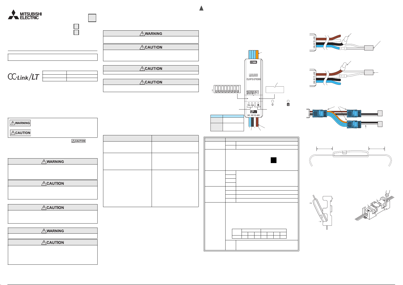
2. Name and Setting of Each Part
Flat cable dedicated
to CC-Link/LT
DIP switch
(Remove the switch cover
when setting the DIP switch.)
DIP switch assignment
40 20 10
ON
Status indicator LEDs
LED name
PW
L RUN
HLD
8
4 2 1
Operation
Lit while the
power is supplied.
Lit while normal
operation is
executed.
Blue
Black
White
Switch cover
(Make sure to attach the
switch cover after setting
the DIP switch.)
Attach it with
this area facing
upward.
Input
operation
indicator
Input/output is ON: Lit
Input/output is OFF: Extinguished
Flat cable for I/O
Brown
operation
LED
Output
indicator
LED
Name Description
Status indicator
LED
I/O operation
indicator LED
Flat cable
dedicated to CCLink/LT
PW ON while the power is s upplied.
L RUN O N while norma l operation is executed.
ON while the input or output is ON.
Extinguished while the input or out put is OFF.
24G
DB
Connector for CC-Link/LT communication line/
module power supply
DA
+24V
Blue 24G
Flat cable for I/O
Black X0
White Y0
Brown +24V
Set the 10's digit of the station No. using "STATIO N NO. 10",
"STATION NO. 20" and "STATION NO. 40". Set the 1's digit of
the station No. using "STATION NO. 1", "STATION NO. 2",
"STATION NO. 4" and "STATION NO. 8".
Factory default = All bits are OFF.
Make sure to set the station No. in the range from 1 to 64.
DIP switch
Example: When setting the station No. to "32", set the
DIP switch as follows.
HLD
10's digit 1's digit
Station
No.
40 20 10 8 4 2 1
32 ONOFFONOFF ON OFF OFF
Holds the output (when an error has occurred).
ON: Holds the output.
OFF: Clears the o utput.
3. Cautions on Handling
3.1 Handling of flat cable for I/O
The cable length from the module to a sensor shall be within 3m(9'10").
Measure the cable outside the module, and confirm that the driving voltage for
the used sensor is ass ured.
• Inp ut
• Outpu t
If the diameter of the I/O equipment connection cable is equivalent to the
diameter of the flat cable for I/O of this module, connectors dedicated to
CC-Link/LT can be used for connection.
3.2 Handling of cable
Do not bend the cable within 3 0 mm (1.18") from the module.
Use a crimp-style terminal in a status in which no force is applied on the
cable.
3.3 Mounting with the CL1-HLD (module holder)
Refer to the figures below for details on m ounting or removing the rem ote
I/O module when used wi th the CL1-HLD.
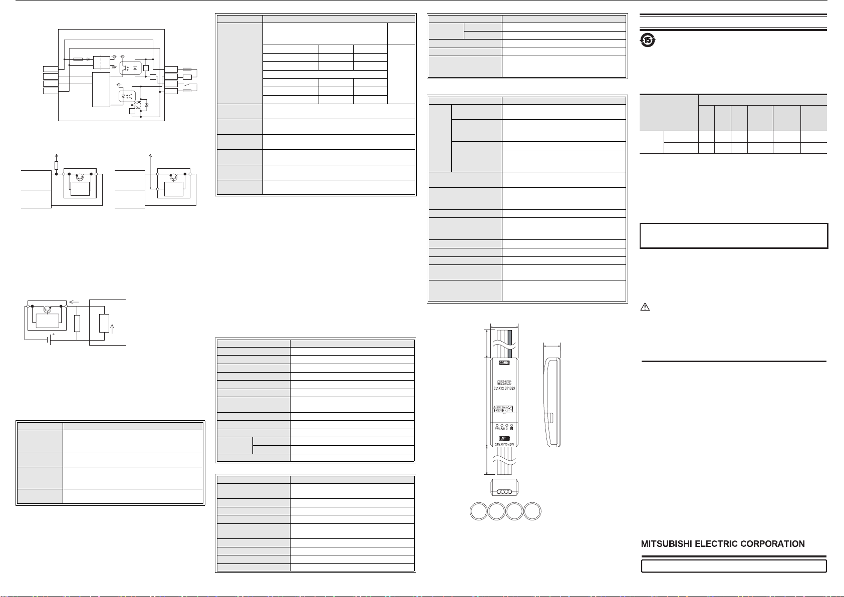
4. Wiring
4.1 External wiring
The input and output terminals of the CL1XY2-DT1D5S operate while
using the power supplied from the interface.
When connec ting a sensor to the input terminal, use a sensor of the NPN
open collector transistor type.
The output wiring i s fixed to the sink output.
Specifications subject to change without notice.
HEAD OFFICE : TOKYO BUILDING, 2-7-3 MARUNOUCHI, CHIYODA-KU, TOKYO 100-8310, JAPAN
When exported from Japan, this manual does not require application to the Ministry of Economy,
Trade and Industry for service transaction permission.
This manual confers no industrial property rights or any rights of any other kind, nor
does it confer any patent licenses. Mitsubishi Electric Corporation cannot be held
responsible for any problems involving industrial property rights which may occur as
a result of using the contents noted in this manual.
Warranty
Exclusion of loss in opportunity and secondary loss from warranty liability
Regardless of the gratis warranty term, Mitsubishi shall not be liable for compensation to:
(1) Damages caused by any cause found not to be the responsibility of Mitsubishi.
(2) Loss in opportunity, lost profits incurred to the user by Failures of Mitsubishi products.
(3)
Special damages and secondary damages whether foreseeable or not, compensation
for accidents, and compensation for damages to products other than Mitsubishi products.
(4) Replacement by the user, maintenance of on-site equipment, start-up test run and
other tasks.
• This product has been manufactured as a general-purpose part for general
industries, and has not been designed or manufactured to be incorporated in a
device or system used in purposes related to human life.
• Before using the product for special purposes such as nuclear power, electric power,
aerospace, medicine or passenger movement vehicles, consult with Mitsubishi Electric.
• This product has been manufactured under strict quality control. However
when installing the product where major accidents or losses could occur if the
product fails, install appropriate backup or failsafe functions in the system.
For safe use
Country/Region Sales office/Tel
USA
MITSUBISHI ELECTRIC AUTOMATION, INC.
500 Corporate Woods Parkway, Vernon Hills,
IL 60061, U.S.A.
Tel : +1-847-478-2100/+1-847-478-2500 (NC)
Brazil MITSUBISHI ELECTRIC DO BRASIL
COMERCIO E SERVICOS LTDA.
Avenida Adelino Cardana, 293, 21 andar,
Bethaville, Barueri SP, Brazil
Tel : +55-11-4689-3000
Germany MITSUBISHI ELECTRIC EUROPE B.V.
– German Branch
Mitsubishi-Electric-Platz 1, 40882
Ratingen, Germany
Tel : +49-2102-486-0
UK
MITSUBISHI ELECTRIC EUROPE B.V. UK Branch
Travellers Lane, Hatfield, Hertfordshire,
AL10 8XB, UK
Tel : +44-1707-28-8780
Italy
MITSUBISHI ELECTRIC EUROPE B.V.
– Italian Branch
Centro Direzionale Colleoni - Palazzo Sirio,
Viale Colleoni 7, 20864 Agrate Brianza (MB), Italy
Tel : +39-039-60531/+39-039-6053-342
Spain
MITSUBISHI ELECTRIC EUROPE, B.V.
– Spanish Branch
Carretera de Rubi 76-80-AC.420, E-08190
Sant Cugat del Valles (Barcelona), Spain
Tel : +34-935-65-3131/+34-935-65-2236
France MITSUBISHI ELECTRIC EUROPE B.V.
– French Branch
25, Boulevard des Bouvets, 92741
Nanterre Cedex, France
Tel : +33-1-55-68-55-68
Czech Republic MITSUBISHI ELECTRIC EUROPE B.V.
Czech Branch
Avenir Business Park, Radicka 751/113e,
158 00 Praha5, Czech Republic
Tel : +420-251-551-470
Poland Mitsubishi Electric Europe B.V. Polish Branch
ul. Krakowska 50, 32-083 Balice, Poland
Tel : +48-12-347-65-00
Country/Region Sales office/Tel
Russia
China MITSUBISHI ELECTRIC AUTOMATION
(CHINA) LTD.
Mitsubishi Electric Automation Center,
No.1386 Hongqiao Road, Shanghai, China
Tel : +86-21-2322-3030
Taiwan SETSUYO ENTERPRISE CO., LTD.
6F, No.105, Wugong 3rd Road, Wugu District,
New Taipei City 24889, Taiwan, R.O.C.
Tel : +886-2-2299-2499
Korea MITSUBISHI ELECTRIC AUTOMATION
KOREA CO., LTD.
7F~9F, Gangseo Hangang Xi-tower A, 401,
Yangcheon-ro, Gangseo-Gu, Seoul, 07528, Korea
Tel : +82-2-3660-9530
Singapore MITSUBISHI ELECTRIC ASIA PTE. LTD,
307 Alexandra Road, Mitsubishi Electric
Building, Singapore 159943
Tel : +65-6473-2308
Thailand Mitsubishi Electric Factory Automation
(Thailand) Co., Ltd.
12th Floor, SV.City Building, Office Tower 1,
No. 896/19 and 20 Rama 3 Road, Kwaeng
Bangpongpang, Khet Yannawa,
Bangkok 10120, Thailand
Tel : +66-2682-6522~31
Indonesia PT. Mitsubishi Electric Indonesia
Gedung Jaya 11th Floor, JL. MH. Thamrin
No.12, Jakarta Pusat 10340, Indonesia
Tel : +62-21-3192-6461
India Mitsubishi Electric India Pvt. Ltd.
Gurgaon Head Office
2nd Floor, Tower A & B, Cyber Greens,
DLF Cyber City, DLF Phase - III,
Gurgaon - 122002, Haryana, India
Tel : +91-124-4630300
Australia
MITSUBISHI ELECTRIC AUSTRALIA PTY. LTD.
348 Victoria Road PO BOX11, Rydalmere,
N.S.W 2116, Australia
Tel : + 61-2-9684-7777
Mitsubishi Electric (Russia) LLC
52, bld. 1, Kosmodamianskaya emb.,
115054 Moscow, Russia
Tel : +7-495-721-2070
Note: This symbol mark is for China only.
含有有害6物质的名称,含有量,含有部品
本产品中所含有的有害 6 物质的名称,含有量,含有部品如下表
所示。
产品中有害物质的名称及含量
本表格依据SJ/T 11364的规定编制。
○
:表示该有害物质在该部件所有均质材料中的含量均在GB/T 26572
规定的限量要求以下。
×:表示该有害物质至少在该部件的某一均质材料中的含 量超出GB/T
26572规定的限量要求。
部件名称
有害物质
铅
(Pb)汞(Hg)镉(Cd)
六价铬
(Cr(VI))
多溴联苯
(PBB)
多溴
二苯醚
(PBDE)
可编程
控制器
外壳
印刷基板
○○
○○ ○ ○ ○
○○ ○ ○
×
0
X0 input operation
indicator LED
Y0 output operation
indicator LED
0
Crimp-style connection device with
insulator or closed end connection
device
Sensor,
switch, etc.
Crimp-style connection device with
insulator or closed end connection
device
Lamp,
solenoid, etc.
Input
equipment
Connector dedicated to CC-Link/LT
Output
equipment
Wire diameter: AWG18 (34/0.18)
30mm(1.19") 30mm(1.19")
1)Fit the remote
I/O module in
a corner of the
CL1-HLD.
2)Press down b)
while holding
a).
1)Insert a screwdriver into either a, b, c, or d.
2)Pry the remote I/O module from the
holder using the screwdriver.
Mount Dismount
CL1-HLD
Remote
I/O
module
a)
b)
a
b
c
d
I/O wiring
Unit: mm(inches)
24G X0 Y0
+24V
20(0.79")
65(2.56")500(19.69")
12(0.48")
500(19.69")
CL1XY2-DT1D5S
Flat cable
dedicated
to CC-Link/LT
+24V
DA
DB
24G
DC DC
Internal
circuit
Isolation
Flat cable
for I/O
R
+24V
Y0
R
X0
24G
R
4.2 Connection to sensor
• When using a two-wire type sensoryWhen using a three-wire type sensor
Connected to +24 V
cable
Bleeder resistor *1
X *
24G
Detection
circuit
Sensor (NPN)
Replace * in the figure with the used input No.
Notes:
*1 Bleeder resistor
When connecting a two-wire type sensor or input equipment having parallel
resistor, select a sensor or equipment whose leakage cu rrent is 1.7 mA or
less.
If the leakage cu rrent is more t han 1.7 mA, co nnect a bleede r resistor
obtained in the following calculation formula.
Circuit image
Sensor
Detection
circuit
R (kΩ) < 1.7 (mA) / Leakage current (mA) - 1.7 (mA)
The power capacity W of the bleeder resistor R is as follows:
W = (Input voltage)
• Make sure that both the ON and OFF time of the input s ignal are 1.5ms or
more.
5. Specifications
5.1 General specifications
Item Specification
Ambient
working
temperature
Ambient storage
temperature
Ambient
operating
humidity
Ambient storage
humidity
Leakage
Unit
current
Input impedance
R
24V DC
2
/R
0 to 55°C (32 to 131°F)
-25 to 75°C (-13 to 167°F)
5 to 95%RH: Dew condensation shall no t be considered.
5 to 95%RH: Dew condensation shall no t be considered.
5.6 kΩ
1.7 mA or less
Connected to +24 V
cable
X *
24G
Detection
circuit
Sensor (NPN)
R: Bleeder resistor
5.6 (kΩ)
×
0.5A
0.5A
Item Specification
When intermittent vibration is present
Frequency
Vibration
resistance
L
10 to 57 Hz
57 to 150 Hz
(*1)
When continuous vib ration is present
Frequency
10 to 57 Hz
57 to 150 Hz
Impact
resistance
(*1)
Operating
atmosphere
Operating
altitude
Installation
place
Over-voltage
category
Degree of
contamination
Notes:
*1 The criterion is shown in IEC61131 -2.
*2 The module cannot be used in an environment pres surized above the
atmospheric pressur e which can be generated around the altitude of 0 m. I f the
module is used in such an environmen t, it may fail.
*3 The module can be us ed in any environment even outside the con trol panel as
far as the requir ements of the ambient operating tem perature, the ambient
operating humidity, etc. are satisfied.
*4 This indicates the section of the power supply to which the equipment is
assumed to be connected between the public electrical power distribution
network and the machinery within premises. Category ΙΙ applies to equipment
for which electrical power is supplied from fixed facilities.
The surge voltage withstand level for up to the rated voltage of 300V is 2500V.
*5 This index indicates the degree of conductive generating subst ances in the
environment in which the module is used. The degree of contamination 2 indicates
that contamination is cause d by generation of only non-conductive substances.
In this degree, however, temporary conduction may be caused by accidental
condensation.
2
, 3 times in each of X, Y and Z directions
147 m/s
Corrosive gas shall not be present.
2,000 m (6561'8") or less (*2)
Inside control panel (*3)
or less (*4)
ΙΙ
2 or less (*5)
Acceleration Half amplitude
−
2
9.8 m/s
Acceleration Half amplitude
−
2
4.9 m/s
5.2 Input specifications
Item S pecific ation
Input method
Number of input
Isolation method
Rated inpu t voltage
Rated inpu t curren t
Operating voltage range
Max. simultaneous ON
input points
ON voltage/ON current
OFF voltage/OFF current
Input resistance
Response
time
Common wiring method
OFF→ON
ON→OFF
DC input (using module power supply in comm on)
1 point
Isolation with photocoupler
24 V DC
Approx. 4 mA
Same as module power supply
100% (at 24 V DC)
19 V or more/3 mA or more
11 V or less/1.7 mA or less
5.6 k
Ω
1.5 ms or less ( at 24 V DC)
1.5 ms or less ( at 24 V DC)
1 point/1 common (Mutually exclusive output)
5.3 Output specifications
Item S pecific ation
Output method
Number of output
Isolation method
Rate d load voltag e
Operating load voltage
range
Max. load current
Max. inrush current
Leakage current at OFF
Max. voltage drop at ON
Transistor output
(using module power sup ply in common) (s ink)
1 point
Isolation with photocoupler
24 V DC
Same as module power supply
0.1 A/point 0.2 A/1 common
0.4 A/10 ms
0.1 mA or less/30 V DC
1 V or less (max.)/0.1 A
0.075 mm
−
0.035 mm
−
Number
of times of
sweep
10 times
in each of
X, Y and Z
directions
(for 80
min)
Item S pecification
Response
time
OFF→ON
ON→OFF
Surge suppression
Common wiring method
Internal protection for
outputs
1.0 ms or less
1.0 ms or less
Zener diode
1 point/1 common (Mutually exclusive output)
Internal protecti on circuit none
Please connect the fuse in the conn ected load
outside.
5.4 Performance specifications
Item Specification
Vol ta ge
Module
power
supply
Number of stations
occupied
Current
consumption
Initial current
Max. allowable
momentary power
failure period
Noise dur ability
Withstand voltage
Isolation resistance
Protection class
I/O part connection method
Module installation method
Flat cable for I/O (wire
diameter)
Mass (weight)
20.4 to 28.8 V DC (24 V DC -15% to +20%)
Ripple ratio: Within 5%
40 mA (when all points are ON)
(Current consumption contains neither t he input
current nor the load current.)
70 mA
PS1:1 ms
4-, 8- or 16-point mode: 1 station
500 Vp-p
Noise width: 1µs Cycle: 25 to 60 Hz
(by noise simulator)
500 V AC for 1 min
10 MΩ or higher between primar y area (external
DC terminal) and second ary area (inter nal circuit)
by 500V DC insulation resistance tes ter
IP2X
Connection with cable
Can be installed in six directions
AWG18 (34/0.18)
0.07 kg (0.15 lbs )
(including 500 mm (19.69") flat cable dedic ated to
CC-Link/LT and 500 mm (19.69") flat cable for I/O)
6. Outside Dimensions
 Loading...