

Page 1
Series
MULTIPLE SPLIT TYPE AIR CONDITIONERS
Series
CM05EU4-D
Page 2
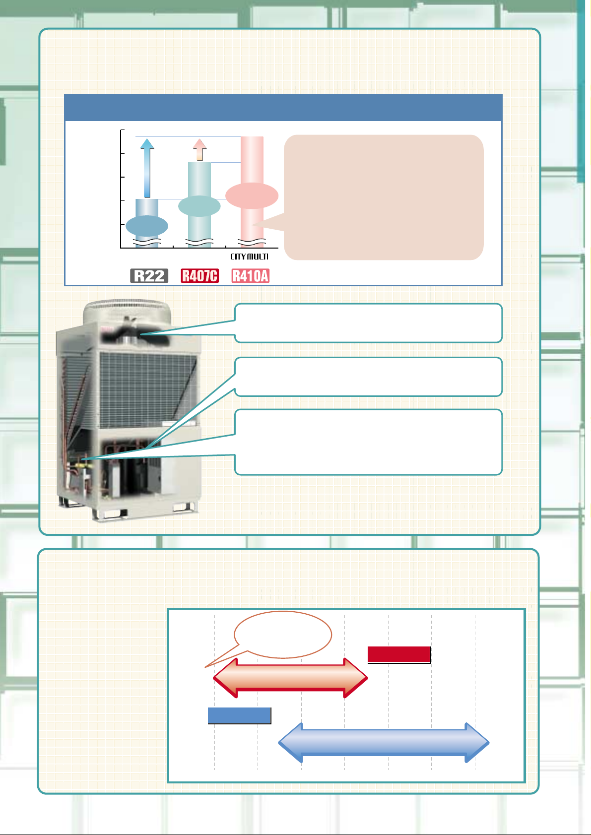
Comparison of COP (energy consumption efficiency) <10 HP system>
50%
Energy
saving
14.5%
Energy
saving
2.0
0
2.5
3.0
3.5
4.0COP
2.58
3.39
3.88
2.58
3.39
3.88
Our equivalent
product 10 years
before
CITY MULTI
Comparing to the current energy
saving type,
COP upgraded by about 15%!
COP upgraded by about 15%!COP upgraded by about 15%!
Comparing to our equivalent product
10 years before,
(10HP equivalent model)
COP upgraded by about 50%!
COP upgraded by about 50%!COP upgraded by about 50%!
Resulting in Total Energy
Conservation
Resulting in Total Energy
Conservation
Resulting in Total Energy
Conservation
Inverter driven outdoor fan motor
newly employed!
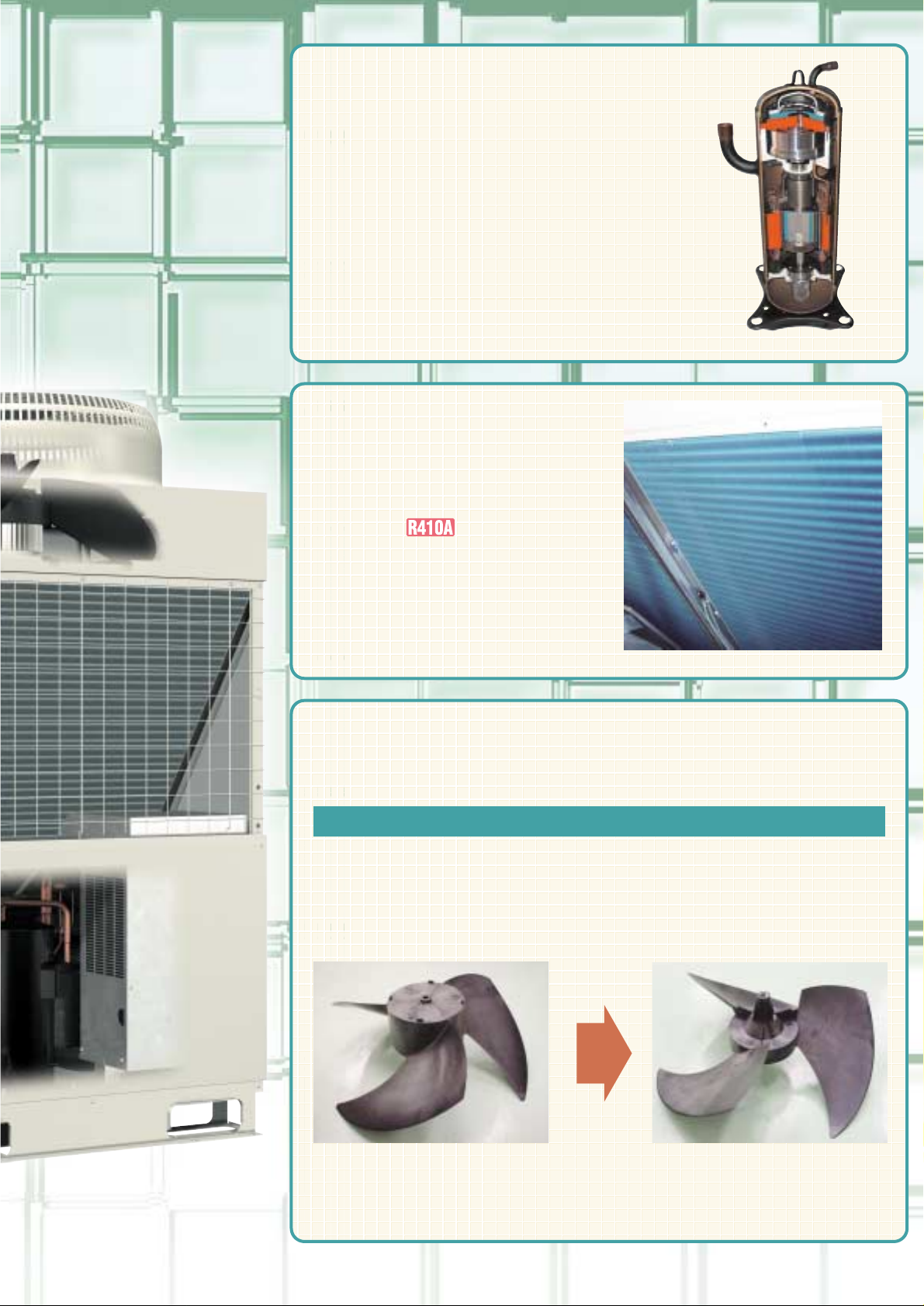
R410A highly efficient inverter
compressor employed!
• Improvement of
heat exchanger performance
• Newly designed refrigerant circuit
(low pressure loss)
High COP
(energy consumption efficiency)
Achieved Top class in the Industry
High COP
(energy consumption efficiency)
Achieved Top class in the Industry
High COP
(energy consumption efficiency)
Achieved Top class in the Industry
Operating range in
cooling is from an
outdoor temperature
of -5˚C, while that in
heating has
expanded to an
outdoor temperature
of -20˚C!
The operation range
can now cover even
cold regions.
✻-12˚C~15˚C for
PUMY series.
-20 -10 0 10 20 30 40
Under cooling
Outdoor temperatureOutdoor temperature
(dry bulb temperature)ulb temperature)
Outdoor temperature
(dry bulb temperature)
Outdoor temperatureOutdoor temperature
(wet bulb temperature)ulb temperature)
Outdoor temperature
(wet bulb temperature)
-20˚C 15.5˚C
-5˚C 43˚C
-20˚C 15.5˚C
-5˚C 43˚C
-20˚C 15.5˚C
-5˚C 43˚C
Operable even in
very cold regions
Under heating
Heating operation range covers an outdoor
temperature of down to -20˚C
(wet bulb temperature)
Heating operation range covers an outdoor
temperature of down to -20˚C
(wet bulb temperature)
Heating operation range covers an outdoor
temperature of down to -20˚C
(wet bulb temperature)
✻✻
Page 3
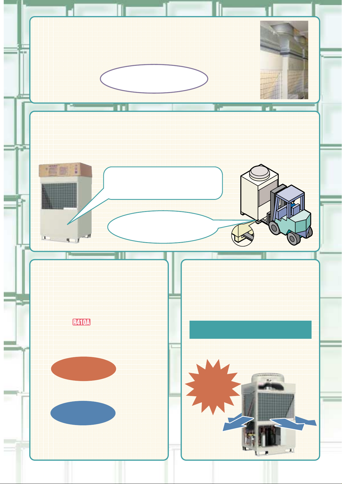
Flexibility in air conditioning design has been enlarged with a high static
pressure of 60Pa.
(except PUMY series)
The use of wooden frame for the transport of the outdoor unit has been discontinued. The structure is so designed that the unit can be
transported with a forklift not using wooden frames or pallets. This contributes in reducing waste and preserving the global environment.
Outdoor unit packing
without using wooden materials
The front and rear double suction structure
provides the smooth airflow to reduce the
pressure loss, which results in low noise.
The machine compartment is sealed up to
attain the low noise level in all directions.
(except PUMY series)
Air passage and machine
compartment separated
(10HP)
49dB
49dB
49dB
57dB
57dB
57dB
Outdoor unit packing
without using wooden materials
Night Mode Quiet
operation can reduce
sound level of 8dB!
(10HP)
Night Mode Quiet
operation can reduce
sound level of 8dB!
(10HP)
Night Mode Quiet
operation can reduce
sound level of 8dB!
(10HP)
Front and rear double
suction structure
Front and rear double
suction structure
Front and rear double
suction structure
Outdoor unit packing
without using wooden materials
Facilitated connection
of supply hood
*Optional parts
High static pressure of 60Pa
achieved, the industry top class*
High static pressure of 60Pa
achieved, the industry top class*
High static pressure of 60Pa
achieved, the industry top class*
Transportable by a forklift
without using pallets.
Eliminating wood consumption
thanks to the wooden packing
discontinued.
“All
Directions”
“All
Directions”
“All
Directions”
CITYMULTI Series Night mode quiet
operation can reduce sound level by
sensing ambient temperature condition.
above
30˚C
below
30˚C
*Needs to set night mode setting at the site.
*Night mode could be turn off automatically due to ambient
temperature and required capacity load condition.
Page 4
Only with
MITSUBISHI
ELECTRIC
Only with
MITSUBISHI
ELECTRIC
Only with
MITSUBISHI
ELECTRIC
Only with
MITSUBISHI
ELECTRIC
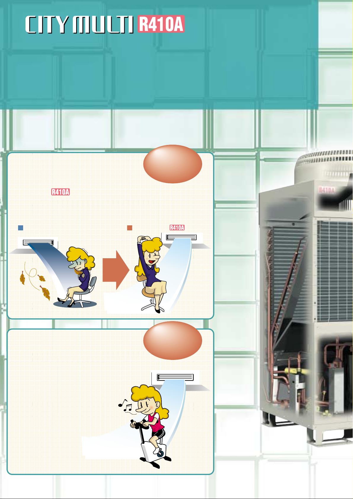
Series provide
for air conditioning comfort with
MITSUBISHI ELECTRIC's
leading edge technologies.
Series provide
for air conditioning comfort with
MITSUBISHI ELECTRIC's
leading edge technologies.
CITYMULTI Series can change the target evaporating
temperature during cooling mode.
Unit with higher off coil temperature can offer more comfort due
less chance of cold draughts.
Less cold draught,
More comfort
Less cold draught,
More comfort
Less cold draught,
More comfort
Cooling Operation
Set Temperature
of 14˚C
Cooling Operation
Set Temperature
of 14˚C
Cooling Operation
Set Temperature
of 14˚C
By selecting a dip switch on the
unit, a cooling operation set
temperature of 14˚C is possible on
the floor standing and ceiling
concealed models. Suitable for
lower set temperature applications
like Gymnasiums etc,,,.
Conventional Model
CITYMULTI Series
(except PUMY series)
Page 5
Motor efficiency greatly improved +
Reduced suction refrigerant heating loss
City Multi Y/R2 VRF systems led the introduction of larger single fan rotors
some ten years ago and achieved substantially lower noise levels over
multiple designs. Continuing development in the areas of blade shape and
weight has achieved higher performance and lower noise level.
CITYMULTI Series will
have an Anti-Corrosion heat
exchanger (Blue Fin) as a
standard.
High-capacity
reluctance DC motor
drive compressor
High-capacity
reluctance DC motor
drive compressor
High-capacity
reluctance DC motor
drive compressor
Industry Top class
Low Noise Design
Anti-Corrosion
Blue Fin as a
Standard!
Anti-Corrosion
Blue Fin as a
Standard!
Anti-Corrosion
Blue Fin as a
Standard!
New Fan Design
Conventional model fan
New model fan
Industry Top class
Low Noise Design
Industry Top class
Low Noise Design
Page 6
Mitsubishi Electric
City Multi Series
– towards a new era of
highly advanced air conditioning –
Mitsubishi Electric
City Multi Series
– towards a new era of
highly advanced air conditioning –
As a market leading company,
Mitsubishi Electric offers the
"State of the Art" City Multi
VRF system, adopting
advanced refrigeration & control
technology, thereby achieving
high performance and ultimate
design flexibility.
As a market leading company,
Mitsubishi Electric offers the
"State of the Art" City Multi
VRF system, adopting
advanced refrigeration & control
technology, thereby achieving
high performance and ultimate
design flexibility.
1
Page 7
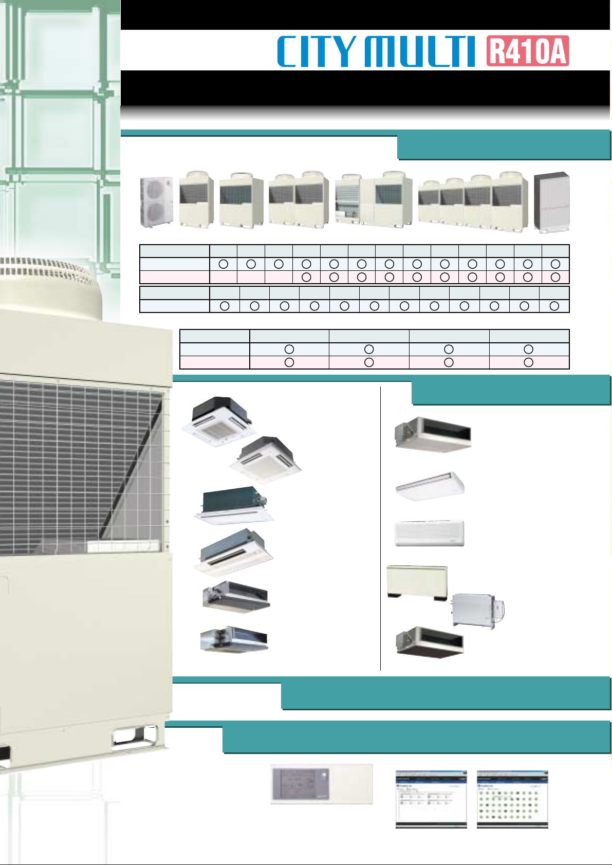
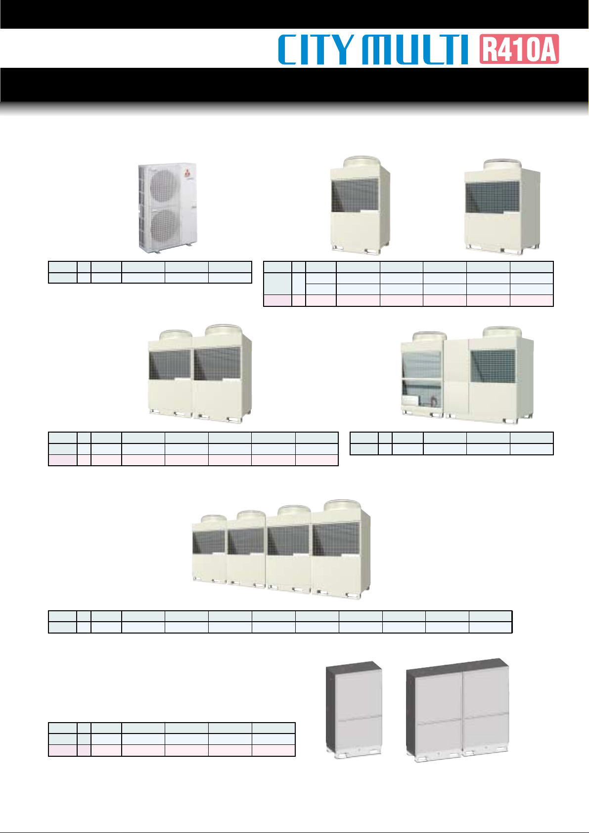
Series Product Lineup
Outdoor Unit
Indoor Unit
Lossnay/
OA Processing Units
Air Conditioning MANAGEMENT SYSTEM
PLFY-P VCM-E/VAM-E
........p.25, 26 / 36, 37
PLFY-P VLMD-E
........p.27 / 38, 39
PEFY-P VMH-E
........p.31 / 44, 45
PCFY-P VGM-E
........p.32 / 46
PEFY-P VMH-E-F
........p.35 / 51, 52
PKFY-P VAM-E/VGM-E
/VFM-E
........p.33 / 47, 48
PFFY-P VLEM-E/VLRM-E
........p.34 / 49, 50
PMFY-P VBM-E
........p.28 / 40
PEFY-P VMM-E
........p.29 / 41, 42
PEFY-P VML-E
........p.30 / 43
8HP5HP4HP3HP 10HP 12HP 14HP 16HP 18HP 20HP 22HP 24HP 26HP
Heat Pump
Heat Recovery
8HP 10HP 16HP 20HP
Heat Pump
Heat Recovery
Air Cooled System
Water Cooled System
50HP48HP46HP44HP42HP40HP38HP36HP34HP32HP30HP28HP
Heat Pump
2
Page 8
FEATURES
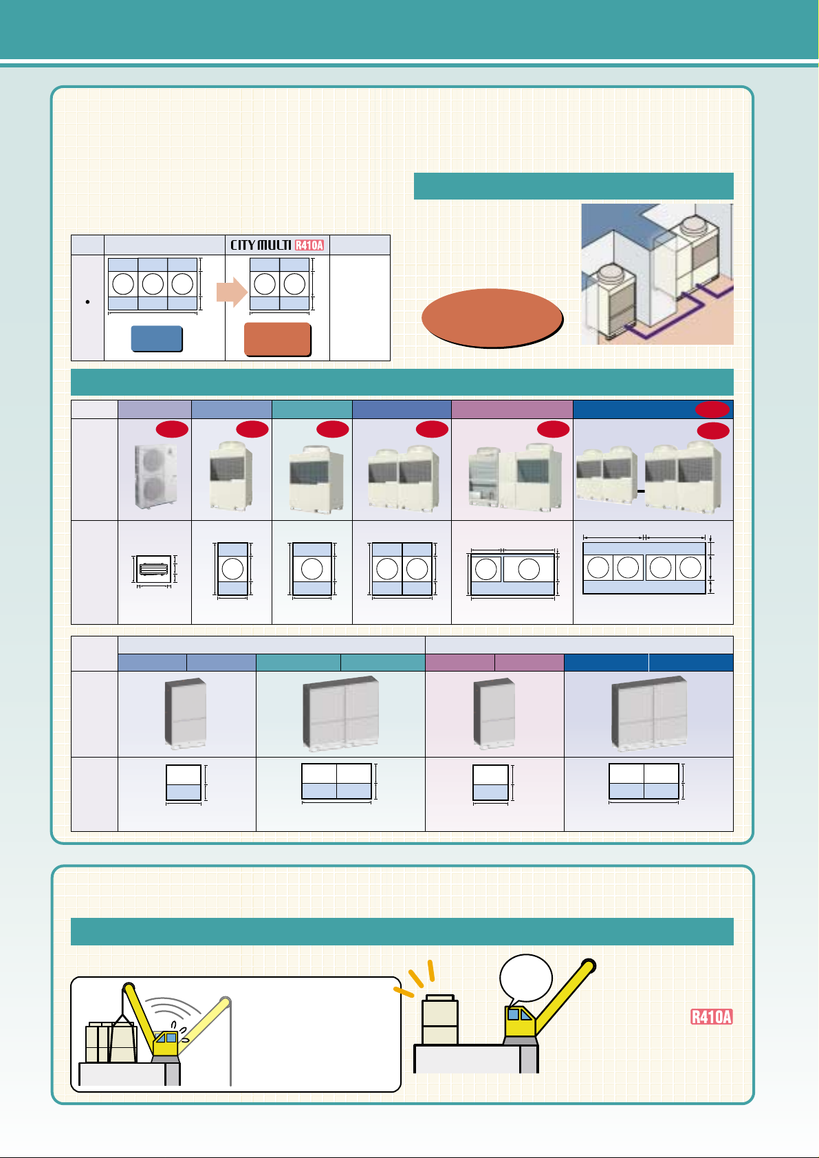
The installation space of the outdoor unit has
greatly been reduced. The reduction counts for
about 33%* maximum comparing to our
conventional CITY MULTI Series.
*24·26HP outdoor units
Effective space utilization thanks to a
small installation space.
Effective utilization of vacant spaces
Outdoor unit installation space (including service space)
Effective space utilization thanks to a
small installation space.
Effective space utilization thanks to a
small installation space.
Easy carrying-in by single package design
Easy carrying-in by single package designEasy carrying-in by single package design
Easy installation
even in a
narrow space
24
26
HP
5.20m
2
3.46m
2
conventional CITY MULTI
1990
840
450
450
2990
840
450
450
33%
reduction
The compact design
and isolated installation
of each unit allow
utilization of vacant
spaces effectively.
For lifting up to building rooftop with a crane
Reduced carrying-in process thanks to the single package configuration
The CITY MULTI
(3~26HP) can be
delivered in one go,
thus allowing far
speedier installation.
Easy installation
even in a
narrow space
For field
combining type
As the lifting up and
down operation is
repeated frequently, the
installation work longer.
One
shot
*Image of 28~32HP system
0.99m
2
1.98m
2
0.99m
2
1.98m
2
8HP
WY Series (Heat Pump) WR2 Series (Heat Recovery)
10HP 16HP 20HP 8HP 10HP 16HP 20HP
Installation Space
(upside piping)
Water Cooled
990
450
550
1,980
450
550
990
450
550
1,980
450
550
8~14HP3~5HP 16HP 18~26HP 28~32HP 34~50HP
NEW
NEW
1unit
1unit
1unit
1unit
1unit
1unit
1unit
1unit
2units
2units
2units
2units
6.94m
2
450
840
450
1990 1990
10
1.72m
2
0.61m
2
2.24m
2
3.46m
2
3.74(4.14)m
2
990
95010 10
840
450
450
330
150
150
1740
630
1290
840
450
450
1740
1990
840
450
450
1740
Installation Space
Air Cooled
1390
(1540)
2690
10
990 1690
840
100
(250)
450
3
Page 9
The World's First and Only "2-Pipe" Heat Recovery SystemThe World's First and Only "2-Pipe" Heat Recovery System
The World's First and Only "2-Pipe" Heat Recovery SystemThe World's First and Only "2-Pipe" Heat Recovery SystemThe World's First and Only "2-Pipe" Heat Recovery System
Achieving smallest number
of pipework connection
thanks to 2-pipe system
Achieving smallest number
of pipework connection
thanks to 2-pipe system
Achieving smallest number
of pipework connection
thanks to 2-pipe system
Heat Recovery System can
create maximum of 15HP
capacity from 10HP unit!
Heat Recovery System can
create maximum of 15HP
capacity from 10HP unit!
Heat Recovery System can
create maximum of 15HP
capacity from 10HP unit!
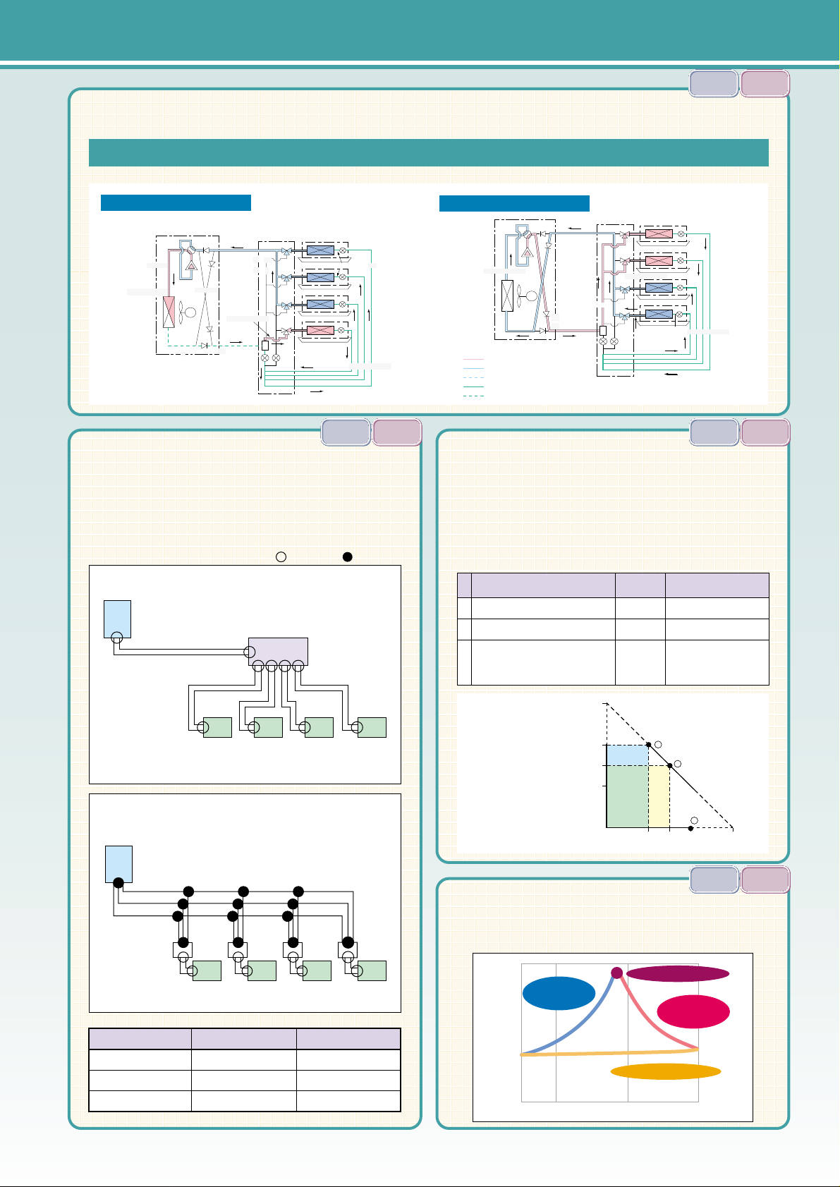
The Innovative BC Controller Which Makes a 2-pipe System Possible
BC Controller Operation
Operation primarily for cooling
Total heat recovery operation
High pressure gas
Low pressure gas
High pressure 2-phase
Low pressure 2-phase
High pressure liquid
Outdoor unit
4-way valve
High
pressure
gas
Low pressure gas
Low pressure gas
Low pressure gas
Low pressure gas
Low pressure gas
High
pressure gas
High
pressure gas
Heat
exchanger
Check valve
Compressor
Fan
Low pressure pipe
Gas/liquid
separator
High pressure 2-phase
High pressure pipe
BC controller
Switching valve
Indoor unit
Low pressure 2-phase
High pressure liquid
Cooling
Cooling
Cooling
Heating
LEV
Operation primarily for cooling
High
pressure gas
Total heat recovery operation
Low pressure 2-phase
High pressure liquid
Cooling
Cooling
Heating
Heating
Comparison of piping connection
=2 connections =3 connections
Indoor unit output
Heating 10HP, Cooling 5HP, Total 15HP
A
B
C
Outdoor unit
input
Heating 7.5HP, Cooling 7.5HP, Total 15HP
Cooling 10HP
Cooling capacity of each indoor
unit is approx. 10/15 of the rating.
Number of branches
4
10
16
2-pipe type
20
44
68
3-pipe type
58
154
–
10HP
7.5HP
10HP
Cooling 5HP: Waste heat utilized
Optimum operation pattern
In the same mode, the
compressor capacity is the
maximum output
(in this case 10HP).
()
The waste heat recovery system in the refrigerant system increases the energysaving effect as the cooling and heating simultaneous operation is carried out.
The more frequently cooling and heating simultaneous
operation is carried out, the higher the energy-saving effect is.
COP in heat recovery operation
0
1
2
3
4
5
6
7
8
20 40 60 80 100
Heating
ratio
Energy consumption efficiency (COP)
Cooling and heating
simultaneous and primarily
cooling operation
Cooling and heating
simultaneous and primarily
heating operation
Cooling and heating non-simultaneous model
Cooling and heating balance operation
15HP
10HP
7.5HP
5HP
5HP 7.5HP 10HP
Primarily heating operationA
Cooling indoor unit
Heating indoor unit
15HP
Total heat recovery operation
B
C
Total 15HP indoor
unit is connected with
10HP outdoor unit.
()
Operation pattern of
New City Multi R2 System
City Multi R2/WR2
3-pipe type
Outdoor unit
Outdoor unit
Branch unit
The total number of connections for City Multi R2 is only
68 when the 16 indoor units are installed.
Indoor unit
Indoor unit
BC Controller
Total number of connections
20
Total number of connections
58
R2
R2
R2
WR2
WR2
WR2
R2
R2
R2
WR2
WR2
WR2
R2
R2
R2
WR2
WR2
WR2
R2
R2
R2
WR2
WR2
WR2
4
Page 10
FEATURES
Eliminating the
oil equalizing pipe
(8~32HP)
Eliminating the
oil equalizing pipe
(8~32HP)
Downsizing of refrigerant
piping connections
Downsizing of refrigerant
piping connections
Downsizing of refrigerant
piping connections
Upgrading reliability by minimizing the number
of parts and providing back up function
Upgrading reliability by minimizing the number
of parts and providing back up function
Upgrading reliability by minimizing the number
of parts and providing back up function
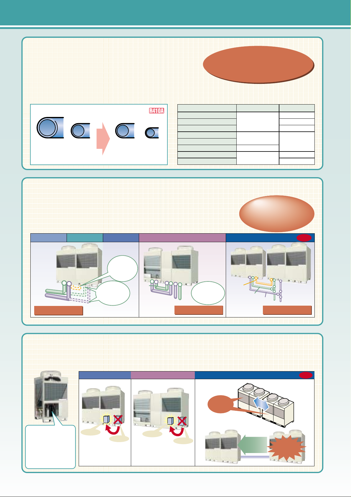
By making the connection diameter of refrigerant piping
smaller, the piping space can be minimized, and the ease of field
installation. Workability upgraded and the piping materials reduced.
Comparison of piping size (for 10HP system)
Conventional type CITY MULTI
type
Gas
piping
φ28.58
Liquid
piping
φ12.7
Gas
piping
φ22.2
Liquid
piping
φ9.52
Facilitating
maintenance work by
minimizing the number
of parts, and
upgrading reliability by
simplifying
construction designed
Gas piping : downed by
2
sizes
Liquid piping : downed by
1
size
(10HP system)
Gas piping : downed by
2
sizes
Liquid piping : downed by
1
size
(10HP system)
List of major piping sizes
Significant reduction of field piping connections
Significant reduction of field piping connectionsSignificant reduction of field piping connections
The single package design eliminates the oil equalizing pipe and
the piping between outdoor units, thus upgrading the reliability,
reducing complexity and reducing the installation cost.
*The actual product may differ from the photo.
3~14HP 16HP 18~26HP 28~32HP 34~50HP
NEW
NEW
Connection spot : 2
Connection spot : 2
Liquid piping
Gas
piping
Oil equalizing
pipe not
required
Piping between
units not
required
Liquid
piping
Gas piping
Gas piping
Liquid
piping
Connection spot : 6
Connection spot : 6
Connection spot : 12
Connection spot : 12
Oil equalizing
pipe not
required
CompressorCompressor
bacbackup operationkup operation
CompressorCompressor
bacbackup operationkup operation
18~26HP 28~32HP 34~50HP
NEW
NEW
CompressorCompressor
bacbackup operationkup operation
CompressorCompressor
bacbackup operationkup operation
Compressor
Compressor
Compressor
backup operation
Compressor
backup operation
Alternate
operation
Alternate
operation
Alternate
operation
Backup
operation
Backup
operation
In case ofIn case of
mulfunctionulfunction
In case ofIn case of
malfunctionmalfunction
In case of
malfunction
Compressor
Compressor
In case of one
compressor fails,
In case of one
compressor fails,
Oil equalizing
piping
Liquid
piping
Gas
piping
In case of one
compressor fails,
In case of one
compressor fails,
System capacity
3~5HP system
8HP system
10/12HP system
14HP system
16HP system
18~26HP system
28~32HP system
34~50HP system
Liquid piping
φ9.52
φ12.7
φ15.88
φ19.05
Gas piping
φ15.88
φ19.05
φ22.2
φ28.58
φ34.93
φ41.28
5
Page 11
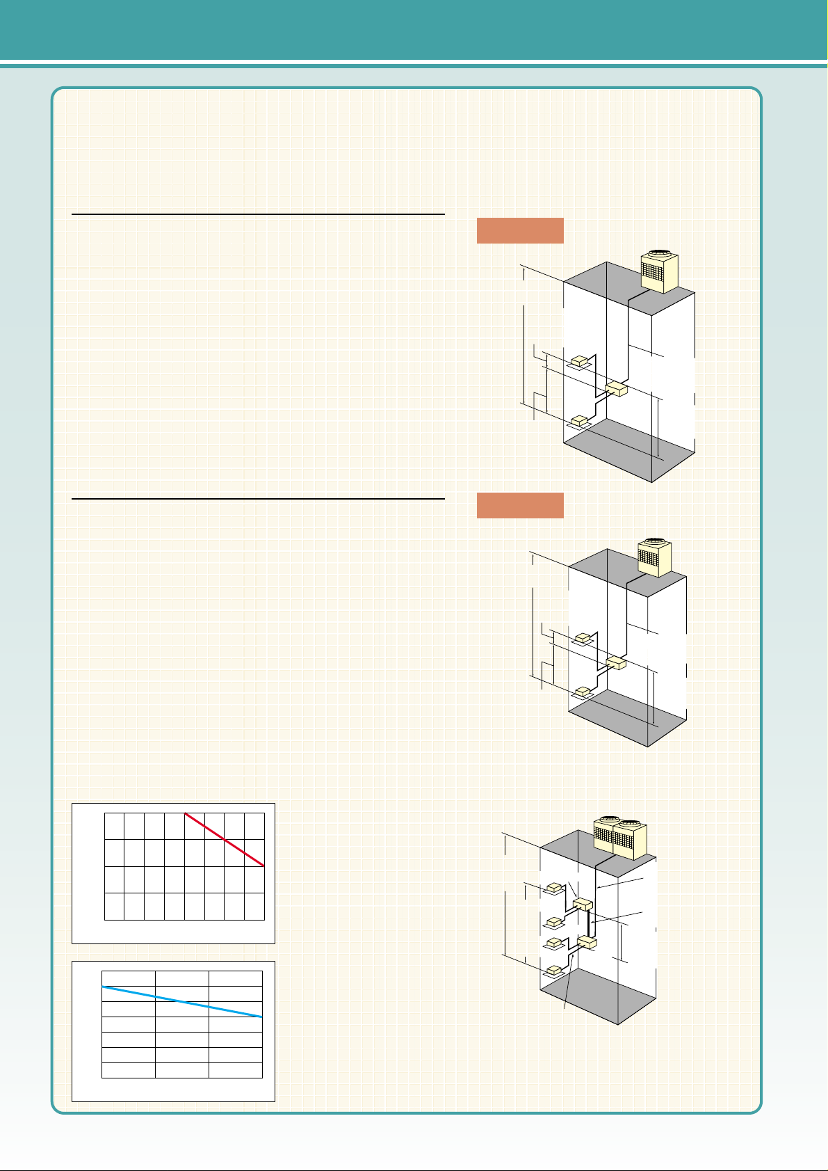
Realizing refrigerant piping total length of
400m* top class in industry
*CITY MULTI R2 Series*CITY MULTI R2 Series
Realizing refrigerant piping total length of
400m* top class in industry
*CITY MULTI R2 Series*CITY MULTI R2 Series
Realizing refrigerant piping total length of
400m* top class in industry
*CITY MULTI R2 Series
Y Series (8~32HP)
Refrigerant Piping Restrictions
Total length........................................................ 300m or less
Furthest length.................................................. 150m or less
Furthest length [equivalent length]................... 175m or less
Furthest length after first branch....................... 40m or less
Top-bottom differentials between units
Between indoor unit and outdoor unit
(outdoor unit is upper)...................................... 50m or less
Between indoor unit and outdoor unit
(outdoor unit is lower)........................................ 40m or less*
Between indoor units......................................... 15m or less
* 4m or less in cooling at outdoor temperature 0˚C or lower.
Y Series (34~50HP)
Refrigerant Piping Restrictions
Total length........................................................ 300m or less
Furthest length.................................................. 150m or less
Furthest length [equivalent length]................... 175m or less
Furthest length after first branch....................... 40m or less
Between Main and Sub outdoor unit................. 4m or less
Top-bottom differentials between units
Between indoor unit and outdoor unit
(outdoor unit is upper)...................................... 50m or less
Between indoor unit and outdoor unit
(outdoor unit is lower)........................................ 40m or less*
Between indoor units......................................... 15m or less
Between Main and Sub outdoor unit................. 0.1m or less
* 4m or less in cooling at outdoor temperature 0˚C or lower.
Furthest piping length
175m (equivalent length)
(actual length 150m)
between indoor units
top-bottom differential
15m
Outdoor unit
Indoor unit
Top-bottom differential 50m
Y Series
Furthest piping length
175m (equivalent length)
(actual length 150m)
between indoor units
top-bottom differential
15m
Outdoor unit
Indoor unit
Top-bottom differential 50m
S Series (3~5HP)
Refrigerant Piping Restrictions
Total length........................................................ 120m or less
Furthest length.................................................. 80m or less
Furthest length after first branch....................... 30m or less
Top-bottom differentials between units
Between indoor unit and outdoor unit
(outdoor unit is upper)...................................... 30m or less
Between indoor unit and outdoor unit
(outdoor unit is lower)........................................ 20m or less
Between indoor units......................................... 12m or less
6
Page 12
FEATURES
R2 Series (P200 ~ P650 type)
Refrigerant Piping Restrictions
Total length............................................................ 300m or less (400m) *1
Furthest length...................................................... 150m or less
Furthest length [equivalent length]........................ 175m or less
Difference between outdoor unit and
BC controller main-unit.......................................... 110m or less
Difference between BC controller
main-unit and furthest indoor unit.......................... 40m or less *2
Top-bottom differentials between units
Between indoor unit and outdoor unit [outdoor unit is upper]
.... 50m or less
Between indoor unit and outdoor unit [outdoor unit is lower]
..... 40m or less
Between indoor unit and BC controller................... 15m or less
Between indoor units............................................. 15m or less (10m)*3
Between BC controller main-unit and sub-unit
.............. 15m or less
Between indoor unit (BC controller main-unit)
and indoor unit (BC controller sub-unit)
....................... 15m or less (10m)*3
* If indoor units (over 16 branches) are connected, two BC controller units are required and there must be three pipes
between BC controllers.
*1. Please refer to 'refrigerant piping limits' (see the figure) in case of the total length is greater than 300m.
*2. Please refer to 'Limits between BC controller - indoor unit' (see the figure) in case of the piping length between
BC controller and furthest indoor unit is greater than 40m (except P250 indoor unit).
*3. Value in ( ) is applied to the P200/P250 type indoor unit.
*4. Do not use joint or header for P200/P250 type indoor unit.
R2 Series (P200, P250, P300, P350 type)
Refrigerant Piping Restrictions
Total length............................................................ 300m or less (400m) *2
Furthest length...................................................... 150m or less
Furthest length [equivalent length]........................ 175m or less
Difference between outdoor unit and
BC controller unit................................................... 110m or less
Difference between BC controller
main-unit and furthest indoor unit....................... 40m or less
*3
Top-bottom differentials between units
Between indoor unit and outdoor unit (outdoor unit is upper)
.... 50m or less
Between indoor unit and outdoor unit (outdoor unit is lower)
..... 40m or less
Between indoor unit and BC controller................... 15m or less (10m) *1
Between indoor units............................................. 15m or less (10m) *1
*1. Value in ( ) is applied to the P200/P250 type indoor unit.
*2. Please refer to 'refrigerant piping limits' (see the figure) in case of the total length is greater than 300m.
*3. Please refer to 'Limits between BC controller - indoor unit' (see the figure) in case of the piping length between
BC controller and furthest indoor unit is greater than 40m (except P250 indoor unit).
*4. Do not use joint or header for P200/P250 type indoor unit.
*5. Do not connect P200/P250 type indoor unit with the indoor unit of any other capacity at a same branch port.
In case of a BC controller unit
(16 branches or less)
Between indoor units
top-bottom
differential 15m
Outdoor unit
Between indoor unit and
BC controller topbottom differential 15m
Between indoor unit and
BC controller
top-bottom differential 15m
Top-bottom
differential 50m
Furthest piping length
175 m (equivalent length)
(actual length 150 m)
P200 ~ P650 types
In case of two BC controller units
(Over 16 branches)
Between indoor
units
topbottom
differential
15m or less
Outdoor unit
Maximum length between indoor unit and
BC controller 40 m or less (2-pipe)
Between distribution
controls top-bottom
differential 15m or less
Top-bottom
differential
50m or less
Main pipe and
branch pipe: 2-pipe
Three pipes between
BC controllers
Distribution sub-control
110 m or less between outdoor
unit and BC controller (2-pipe)
Distribution Distribution
control control
main-unit main-unit
Distribution
control
main-unit
Between indoor units
top-bottom
differential 15m
Outdoor unit
Between indoor unit and
BC controller topbottom differential 15m
Between indoor unit and
BC controller
top-bottom differential 15m
Difference of
height 50m
Furthest piping length
175m (equivalent length)
(actual length 150m)
P200, P250, P300, P350 types
R2 Series
R2 Series
Realizing refrigerant piping total length of
400m* top class in industry
*CITY MULTI R2 Series*CITY MULTI R2 Series
Realizing refrigerant piping total length of
400m* top class in industry
*CITY MULTI R2 Series*CITY MULTI R2 Series
Realizing refrigerant piping total length of
400m* top class in industry
*CITY MULTI R2 Series
• Refrigerant Piping Limits
• Limits between BC contoller - indoor unit
200
30
0 5 10 15
40 50 60 70 80 90 100 110
250
300
350
400
70
60
50
40
30
20
10
0
Distance between outdoor unit and BC Controller (m)
Piping total lenght (m)
Distance between BC controller (Main) -
furthest indoor unit (m)
Height differential between BC controller (Main) - furthest indoor unit (m)
7
Page 13
Series Product Lineup
Heat Pump
Heat Recovery
8HP 10HP 16HP 20HP
Heat Pump
34HP
PUHY-P850YSGM-A
36HP
PUHY-P900YSGM-A
38HP
PUHY-P950YSGM-A
40HP
PUHY-P1000YSGM-A
42HP
PUHY-P1050YSGM-A
44HP
PUHY-P1100YSGM-A
46HP
PUHY-P1150YSGM-A
48HP
PUHY-P1200YSGM-A
50HP
PUHY-P1250YSGM-A
18HP 20HP 22HP
PUHY-P450YGM-A
PURY-P450YGM-A
PQHY-P200YGM-A
PQRY-P200YGM-A
PQHY-P250YGM-A
PQRY-P250YGM-A
PQHY-P400YSGM-A
PQRY-P400YSGM-A
PQHY-P500YSGM-A
PQRY-P500YSGM-A
PUHY-P500YGM-A
PURY-P500YGM-A
PUHY-P550YGM-A
PURY-P550YGM-A
Series
WY Series
WR2 Series
Type
A
A
Series
Y Series
R2 Series
Heat Pump
Heat Recovery
22HP
PUHY-P400YGM-A
–
PURY-P400YGM-A
Type
A
A
Series
Y Series
R2 Series
Heat Pump
Cooling Only
Heat Recovery
28HP 30HP 32HP
PUHY-P700YSGM-A PUHY-P750YSGM-A PUHY-P800YSGM-A
Type
A
Series
Y Series
Type
A
Series
Y Series
Heat Pump
24HP 26HP
PUHY-P600YGM-A
PURY-P600YGM-A
PUHY-P650YGM-A
PURY-P650YGM-A
20HP
PUHY-P250YGM-A
PUY-P250YGM-A
PURY-P250YGM-A
18HP
PUHY-P200YGM-A
PUY-P200YGM-A
PURY-P200YGM-A
22HP
PUHY-P300YGM-A
PUY-P300YGM-A
PURY-P300YGM-A
22HP
PUHY-P350YGM-A
PUY-P350YGM-A
PURY-P350YGM-A
Type
A
Series
S Series
Heat Pump
4HP
PUMY-P125YHM
3HP
PUMY-P100YHM
5HP
PUMY-P140YHM
Wide variation of 44 outdoor unit to adapt with various applications.
Type
W
W
Type:A =Air Cooled.
W=Water Cooled.
8
Page 14
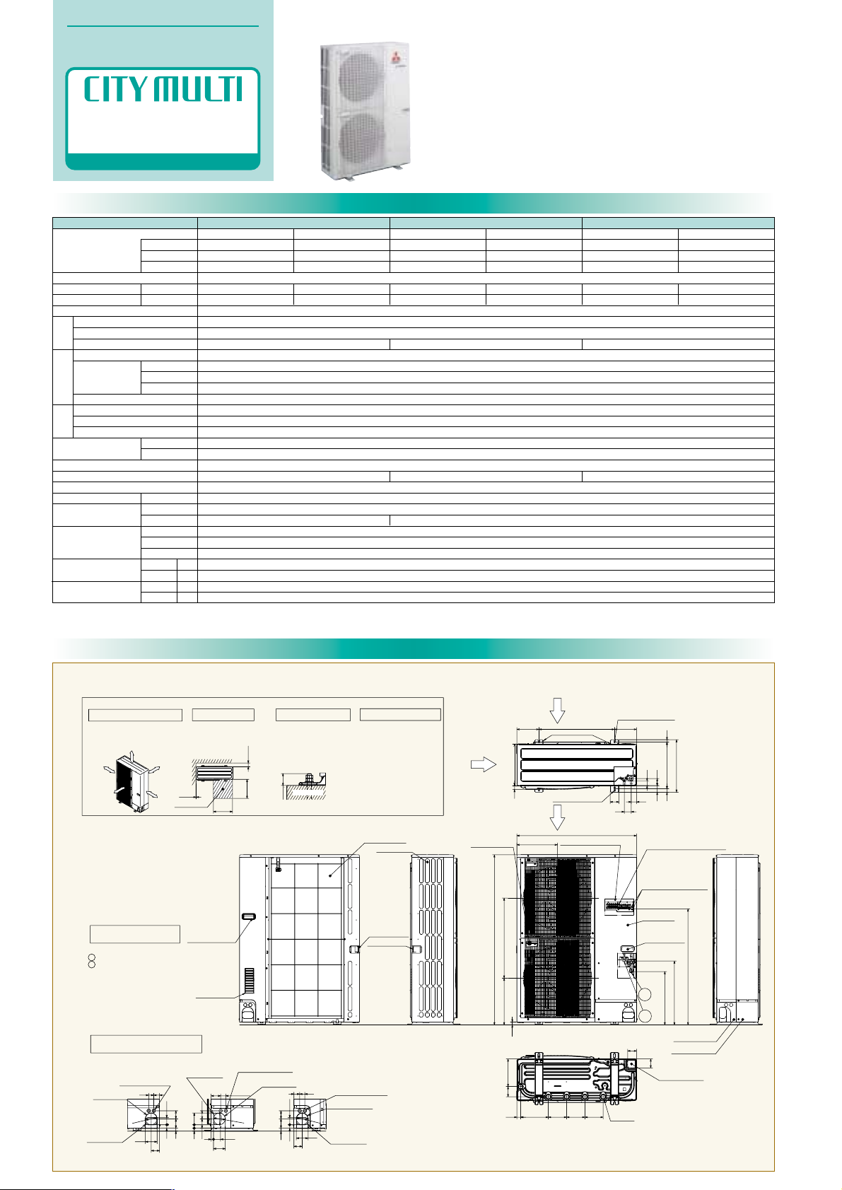
External Dimensions
Specifications
OUTDOOR UNIT
Specifications & External Dimensions
R410A
S SERIES
Model name
PUMY-P125YHMPUMY-P100YHM
Capacity (*1)
Power source
Power input
Current
Heat exchanger type
Type
Starting method
Motor output (kW)
Type ✕ Quantity
Airflow rate
Motor output (kW)
High pressure protection
Inverter circuit
Compressor/fan
Refrigerant type
Noise level (dB) (A-characteristic value) (*3)
External finish
Net weight
Indoor unit
External dimension mm(in.)
Temp. range of cooling
Temp. range of heating
m3/min
L/s
cfm
Gas side
Liquid side
Heating
12.5
–
42,700
Cooling
14.0
12,500
47,800
Heating
16.0
–
54,600
Cooling
11.2
–
38,200
3.20
5.2-4.9-4.7
3.16
5.1-4.9-4.7
4.25
6.8-6.5-6.3
4.27
6.9-6.5-6.3
3-phase 4-wire 380/400/415V 50Hz
Salt-resistant cross fin & copper tube
Inverter scroll hermetic comp.
Inverter
2.4
Propeller fan ✕ 2
100
1,667
3,532
0.06 ✕ 2
High pressure sensor, High pressure switch 4.15MPa
Over-heat protection, Over-current protection
Discharge thermo protection, Over-current protection / Over-heat protection, Voltage protection
φ9.52(φ3/8") Flare
φ15.88(φ5/8") Flare
R410A
Galvanized steel sheet<MUNSEL 3Y 7.8/1.1>
142
50~130% of outdoor unit capacity
1,350 (53-3/16")
950 (37-7/16")
330 (13")
15~24˚C (59~75˚F)
-5~46˚C (23~115˚F)
15~27˚C (59~81˚F)
-12~15˚C (10~59˚F)
1.9 2.9
49
P20~P125 / 1~6 P20~P140 / 1~8
50
kW(*1)
kcal/h(*2)
BTU/h(*1)
kW
A
Compressor
Fan
Protection
PUMY-P140YHM
Cooling
15.5
14,000
52,900
Heating
18.0
–
61,400
5.10
8.2-7.8-7.5
5.25
8.4-8.0-7.7
51
Note: 1. Cooling/heating capacity indicates the maximum value at operation under the following condition.
*1 (JIS Standard: JIS B8615-1) Cooling 27˚C(81˚F)DB/19˚C(66.2˚F)WB Outdoor: 35˚C(95˚F)DB
Heating Indoor: 20˚C(68˚F)DB Outdoor: 7˚C(44.6˚F)DB/6˚C(42.8˚F)WB
Pipe length: 7.5m(24-9/16Ft) Height difference: 0m
*2 Cooling Indoor: 27˚C(81˚F)DB/19.5˚C(67.1˚F)WB Outdoor: 35˚C(95˚F)DB
Pipe length: 5m(16-3/8Ft) Height difference: 0m
*3 It is measured in anechoic room.
Refrigerant piping diameter
mm(in.)
Unit : mm
PUMY-P100,125,140YHM
Handle for moving
Side Air Intake
Front piping cover
Rear piping cover
Air intake
Rear Air Intake
Handle for moving
Handle for moving
Service panel
Handle for moving
Air Discharge
Rear Air Intake
Side Air Intake
14514522030 145
81 219
71
71
Bottom piping hole
(Knock-Out)
Drain hole
5-[33
600175 175
28 370
705642
56
37
19
53
417
330
Installation Feet
2-12o36 Oval holes
(Foundation Bolt M10)
2-U Shaped notched holes
(Foundation Bolt M10)
30
920
322
635371
950
23
1350
w1 423
w1 507
Handle for moving
1
2
( )
Left····· For the power supply
Center·····For the transmission line
Right····· For concentration control
Terminal connection
Ground for the transmission line
Ground for concentration control
Ground for the power supply
Piping Knock-Out Hole Details
Example of Notes
• • •
Refrigerant GAS pipe connction [15.88 (5/8")Flare
• • •
Refrigerant LIQUID pipe connection [ 9.52 (3/8")Flare
w1
• • •
Indication of STOP VALVE connection location.
1
2
637323
5527
92
65
4045
Power supply wiring hole
(2-[27Knock-Out)
Rear trunking hole
(Knock-Out)
Rear piping hole
(Knock-Out)
[
92
922723
6373
4075
92
5519
Power supply wiring hole
(2-[27Knock-Out)
Right trunking hole
(Knock-Out)
Right piping hole
(Knock-Out)
[
9
2
637323
5527
40 45
65
92
Power supply wiring hole
(2-[27Knock-Out)
Front trunking hole
(Knock-Out)
Front piping hole
(Knock-Out)
[
9
2
kg (lbs)
Total capacity
Model / Quantity
Height (H)
Width (W)
Depth (D)
Indoor
Outdoor
Indoor
Outdoor
W.B.
D.B.
D.B.
W.B.
9
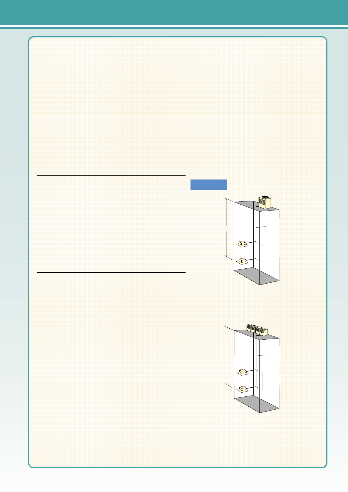
1 FREE SPACE (Around the unit)
The diagram below shows a
basic example.
Explantion of particular details are
given in the installation manuals etc.
O
ve
r
1
0
m
m
FREE
m
0
15
r
ve
O
m
m
0
5
1
r
e
v
O
O
v
e
r
1
0
m
m
m
Over
10
Service space
Dimensions of space needed
for service access are
shown in the below diagram.
Over
500
100
Over
500
Over
3 FOUNDATION BOLTS2 SERVICE SPACE
Please secure the unit firmly
with 4 foundation (M10) bolts.
(Bolts and washers must be
purchased locally.)
<Foundation bolt height>
Less than
30
FOUNDATION
4 PIPING-WIRING DIRECTIONS
Piping and wiring connections
can be made from 4 directions:
FRONT,Right,Rear and Below.
Page 15

Specifications
External Dimensions
Note: 1. Cooling/heating capacity indicates the maximum value at operation under the following condition.
*1 (JIS Standard: JIS B8615-1) Cooling 27˚C(81˚F)DB/19˚C(66.2˚F)WB Outdoor: 35˚C(95˚F)DB
Heating Indoor: 20˚C(68˚F)DB Outdoor: 7˚C(44.6˚F)DB/6˚C(42.8˚F)WB
Pipe length: 7.5m(24-9/16Ft) Height difference: 0m
*2 Cooling Indoor: 27˚C(81˚F)DB/19.5˚C(67.1˚F)WB Outdoor: 35˚C(95˚F)DB
Pipe length: 5m(16-3/8Ft) Height difference: 0m
*3 It is measured in anechoic room.
Model name
4.7
φ19.05(φ3/4") Brazed
φ9.52(φ3/8") Flare
56
218(481)
Models P20~P250/1~13
6.7
φ9.52(φ3/8") Flare (φ12.7(φ1/2") for over 90m)
57
233(514)
Models P20~P250/1~16
8.0
φ9.52(φ3/8") Flare (φ12.7(φ1/2") for over 40m)
59
233(514)
Models P20~P250/1~19
9.6
φ12.7(φ1/2") Flare
60
233(514)
Models P20~P250/1~20
9.7
240
4,000
8,476
0.64
φ12.7(φ1/2") Flare
61
275(607)
Models P20~P250/1~22
1290(50-13/16")
3N ~ 380/400/415V 50/60Hz
Salt Ptotected Fin
Inverter scroll hermetic compressor
Inverter
Propeller fan ✕ 1
High pressure switch 4.15MPa (601 psi)
Over-voltage and over-current protection for AC bus, Over-heat protection
Over-heat protection/Thermal switch
R410A
Pre-coated galvanized sheets + powder coating (for-BS type) <MUNSEL 5Y 8/1 or similar>
50~130% of outdoor unit capacity
1840(72-1/2")
840(33-1/8")
15~24˚C (59~75˚F)
-5~43˚C (23~109˚F) 0~43˚C (32~109˚F)(When the Outdoor is at a position lower than the Indoors)
15~27˚C (59~81˚F)
-20~15.5˚C (-4~60˚F)
φ22.2(φ7/8") Brazed
Capacity
Power source
Power input
Current
Heat exchanger type
Type
Starting method
Motor output (kW)
Type ✕ Quantity
Airflow rate
Motor output (kW)
High pressure protection
Inverter circuit
Compressor/fan
Refrigerant piping diameter
mm(in.)
Refrigerant type
Noise level (dB) (A-characteristic value) (*3)
External finish
Net weight
Indoor unit
External dimension mm(in.)
Temp. range of
cooling
Temp. range of
heating
Gas side
Liquid side
W.B.
D.B.
D.B
W.B.
Indoor
Outdoor
Indoor
Outdoor
kg(lbs)
Total capacity
Model/Quantity
Height (H)
Width (W)
Depth (D)
Compressor
Fan
Protection
PUHY-P200YGM-A PUHY-P250YGM-A PUHY-P300YGM-A PUHY-P350YGM-A PUHY-P400YGM-A
200
3,333
7,063
0.38
990(39")
Model name
6.8 + 5.3
455(1004)
Models P20~P250/1~24
8.2 + 5.3
455(1004)
Models P20~P250/1~24
9.3 + 5.3
455(1004)
Models P20~P250/1~24
10.1 + 5.3
455(1004)
Models P20~P250/1~32
10.9 + 5.3
62/62.5 (50Hz/60Hz)
455(1004)
Models P20~P250/1~32
3N ~ 380/400/415V 50/60Hz
Salt Protected Fin
Inverter scroll hermetic compressor + Scroll hermetic
Inverter + Direct
Propeller fan ✕ 2
400
6,667
14,126
0.38 ✕ 2
High pressure switch 4.15MPa (601 psi)
Over-current protection for AC bus, Over-heat protection
Over-heat protection/Thermal switch
φ28.58(φ1-1/8") Brazed
φ15.88(φ5/8") Flare
R410A
Pre-coated galvanized sheets + powder coating (for-BS type) <MUNSEL 5Y 8/1 or similar>
50~130% of outdoor unit capacity
1840(72-1/2")
1990(78-3/8")
840(33-1/8")
15~24˚C (59~75˚F)
-5~43˚C (23~109˚F) 0~43˚C (32~109˚F)(When the Outdoor is at a position lower than the Indoors)
15~27˚C (59~81˚F)
-20~15.5˚C (-4~60˚F)
kW
A
m
3
/min
L/s
cfm
PUHY-P450YGM-A PUHY-P500YGM-A PUHY-P550YGM-A PUHY-P600YGM-A PUHY-P650YGM-A
60/61 (50Hz/60Hz) 61/62 (50Hz/60Hz)
φ28.58(φ1-1/8") Brazed
kW (*1)
kcal/h (*2)
BTU/h (*1)
Capacity
Power source
Power input
Current
Heat exchanger type
Type
Starting method
Motor output (kW)
Type ✕ Quantity
Airflow rate
Motor output (kW)
High pressure protection
Inverter circuit
Compressor/fan
Refrigerant piping diameter
mm(in.)
Refrigerant type
Noise level (dB) (A-characteristic value) (*3)
External finish
Net weight
Indoor unit
External dimension mm(in.)
Temp. range of
cooling
Temp. range of
heating
Gas side
Liquid side
W.B.
D.B.
D.B
W.B.
Indoor
Outdoor
Indoor
Outdoor
kg(lbs)
Total capacity
Model/Quantity
Height (H)
Width (W)
Depth (D)
Compressor
Fan
Protection
kW
A
m
3
/min
L/s
cfm
kW (*1)
kcal/h (*2)
BTU/h (*1)
PUY-P200YGM-A
Cooling
22.4
20,000
76,400
6.14
10.3/9.8/9.4
Heating
25.0
–
85,300
5.98
10.0/9.5/9.2
Cooling
50.0
45,000
170,600
13.61
22.9/21.8/21.0
Heating
56.0
–
191,100
13.86
23.3/22.2/21.4
Cooling
56.0
50,000
191,100
15.59
26.3/25.0/24.0
Heating
63.0
–
215,000
15.89
26.8/25.4/24.5
Cooling
63.0
55,000
215,000
17.08
28.8/27.3/26.4
Heating
67.0
–
228,600
16.37
27.6/26.2/25.3
Cooling
67.4
60,000
230,000
17.59
29.6/28.2/27.1
Heating
75.0
–
255,900
17.73
29.9/28.4/27.4
Cooling
73.0
65,000
249,100
19.65
33.1/31.5/30.3
Heating
81.5
–
278,100
19.82
33.4/31.7/30.6
Cooling
28.0
25,000
95,500
7.72
13.0/12.3/11.9
Heating
31.5
–
107,500
7.62
12.8/12.2/11.7
Cooling
33.5
30,000
114,300
9.57
16.1/15.3/14.7
Heating
37.5
–
128,000
9.1
15.3/14.5/14.0
Cooling
40.0
35,000
136,500
11.39
19.2/18.2/17.6
Heating
45.0
–
153,500
11.02
18.6/17.6/17.0
Cooling
45.0
40,000
153,500
13.42
22.6/21.5/20.7
Heating
50.0
–
170,600
12.43
20.9/19.9/19.2
PUY-P250YGM-A PUY-P300YGM-A PUY-P350YGM-A
OUTDOOR UNIT
Specifications & External Dimensions
R410A
Y SERIES
Unit : mm
PUHY-P200,250,300,350YGM-A
PUY-P200,250,300,350YGM-A
Note1.Use the opening at the bottom of the unit
when running the power supply line from
the front or from the side of the unit.
Note2.Please refer to (2/2) for information
regarding necessary spacing around the
unit and foundation work.
166
83100
44150
Y
Y
20
70
80
100
90
10
4080
135
280
134
553
494
8057
16065
768
37 117 117 37
A
1575
1840
11
235
16067
990
16
840
67 207
207
67
78
X
X
877
845(mounting pitch)
16
45
900(mounting pitch)
45
265
ø53
12 5
Conn. pipe(Liquid)
200: ø9.52 <Flare>
250: ø9.52 <Flare>
300: ø9.52 <Flare>
350: ø12.7 <Flare>
Conn. pipe(Gas)
200: ø19.05 <Brazed>
250: ø22.2 <Brazed>
300: ø22.2 <Brazed>
350: ø28.58 <Brazed>
136
136
132A200
Model
146
250
300
350
(Mounting hole)
Air outlet
Air
inlet
Air
inlet
ø62 Knockout hole
<Hole for power supply>
Changeable to ø27,ø33 by using
attached conduit mounting plate <Accessory>
ø27 Knockout hole
<Bottom hole for
control wiring>
Knockout hole
<Bottom piping hole>
Left side view
ø27 Knockout hole
<Left side hole for
control wiring>
Knockout hole
<Left piping hole>
<Accessories>
• Refrigerant (Gas) conn. pipe......1 pc.
(P200type:Packaged in the accessory kit)
(P250,P300,P350type:Already installed on the unit)
• Packing for conn. pipe................1 pc.
(P200type:Not attached)
(P250,P300,P350type:Attached near the ball valve)
• Conduit mouting plate
ø33, ø27..............................1 pc.Each
• Tapping screw M4......................2 pcs.
Cross section Y – Y
Cross section X – X
2X2-14X20 0val hole
Top view
Front view
Knockout hole
Service panel
Refrig. service
valve (Liquid)
<Flare>
Refrig. service
valve(Gas)
<Flange>
Knockout hole
<Front piping
hole>
10
Page 16
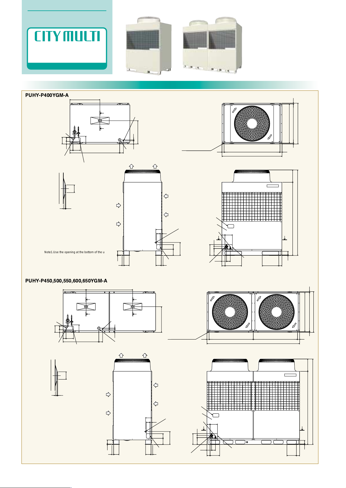
External Dimensions
Unit : mm
PUHY-P400YGM-A
PUHY-P450,500,550,600,650YGM-A
Note1.Use the opening at the bottom of the unit
when running the power supply line from
the front or from the side of the unit.
Note2.Please refer to (2/2) for information
regarding necessary spacing around the
unit and foundation work.
166
83100
44
150
80
280
100134
3711511537
10 89
40
135
80
2070
644
503
145
65
1068
57 80
160
67
235
68
355
1840
2651575
7811
355 68
X
X
840
1290
877
16
45
845(mounting pitch)16
451200(mounting pitch)
160
ø53
12 5
Conn. pipe(Gas)
ø28.58<Brazed>
Conn. pipe(Liquid)
ø12.7<Flare>
(Mounting hole)
Y
Knockout hole
<Bottom piping hole>
ø62 Knockout hole
<Hole for power supply>
Changeable to ø46,ø53 by using
attached conduit mounting plate <Accessory>
ø27 Knockout hole
<Bottom hole for
control wiring>
Air outlet
Air
inlet
Air
inlet
Cross section Y – Y
Cross section X – X
ø27 Knockout hole
<Left side hole for
control wiring>
Knockout hole
<Left piping hole>
Left side view
<Accessories>
• Refrigerant (Gas) conn. pipe......1 pc.
(Already installed on the unit)
• Packing for conn. pipe................1 pc.
(Attached near the ball valve)
• Conduit mouting plate
ø53, ø46.............................1 pc.Each
• Tapping screw M4.....................2 pcs.
Y
2X2-14X20 Oval hole
Knockout hole
Service panel
Refrig. service
valve (Liquid)
<Flare>
Knockout hole
<Front piping
hole>
Refrig. service
valve(Gas)
<Flange>
Front view
Top view
Note1.Use the opening at the bottom of the unit
when running the power supply line from
the front or from the side of the unit.
Note2.Please refer to (2/2) for information
regarding necessary spacing around the
unit and foundation work.
44150
83
162
135
40
8910
37 115 115 37
134 100
280
80
80
20
70
494
145
553
1000
768
80
57
160
65
1840
1575
11
68
68 205 205
100
235
16067
78
265
45
1990
45950(mounting pitch)
877
840
16 16
845(mounting pitch)
950(mounting pitch)
512
ø53
Conn. pipe(Gas)
ø28.58<Brazed>
Conn. pipe(Liquid)
ø15.88<Flare>
YY
YY
X
X
(Mounting hole)
Knockout hole
<Bottom piping hole>
ø27 Knockout hole
<Bottom hole for
control wiring>
ø62 Knockout hole
<Hole for power supply>
Changeable to ø46,ø53 by using
attached conduit mounting plate <Accessory>
<Accessories>
• Refrigerant (Gas) conn. pipe....1 pc.
(Already installed on the unit)
• Packing for conn. pipe......1 pc.
(Attached near the ball valve)
• Conduit mouting plate
ø53, ø46......1 pc.Each
• Tapping screw M4...2 pcs.
Air
inlet
Air
inlet
Air outlet
Cross section X – X
Cross section Y – Y
ø27 Knockout hole
<Left side hole for
control wiring>
Knockout hole
<Left piping hole>
Left side view
Front view
Knockout hole
Service panel
Knockout hole
<Front piping hole>
Refrig. service
valve (Liquid)
<Flare>
Refrig. service
valve(Gas)
<Flange>
Top view
3X2-14X20 Oval hole
OUTDOOR UNIT
Specifications & External Dimensions
R410A
Y SERIES
11
Page 17
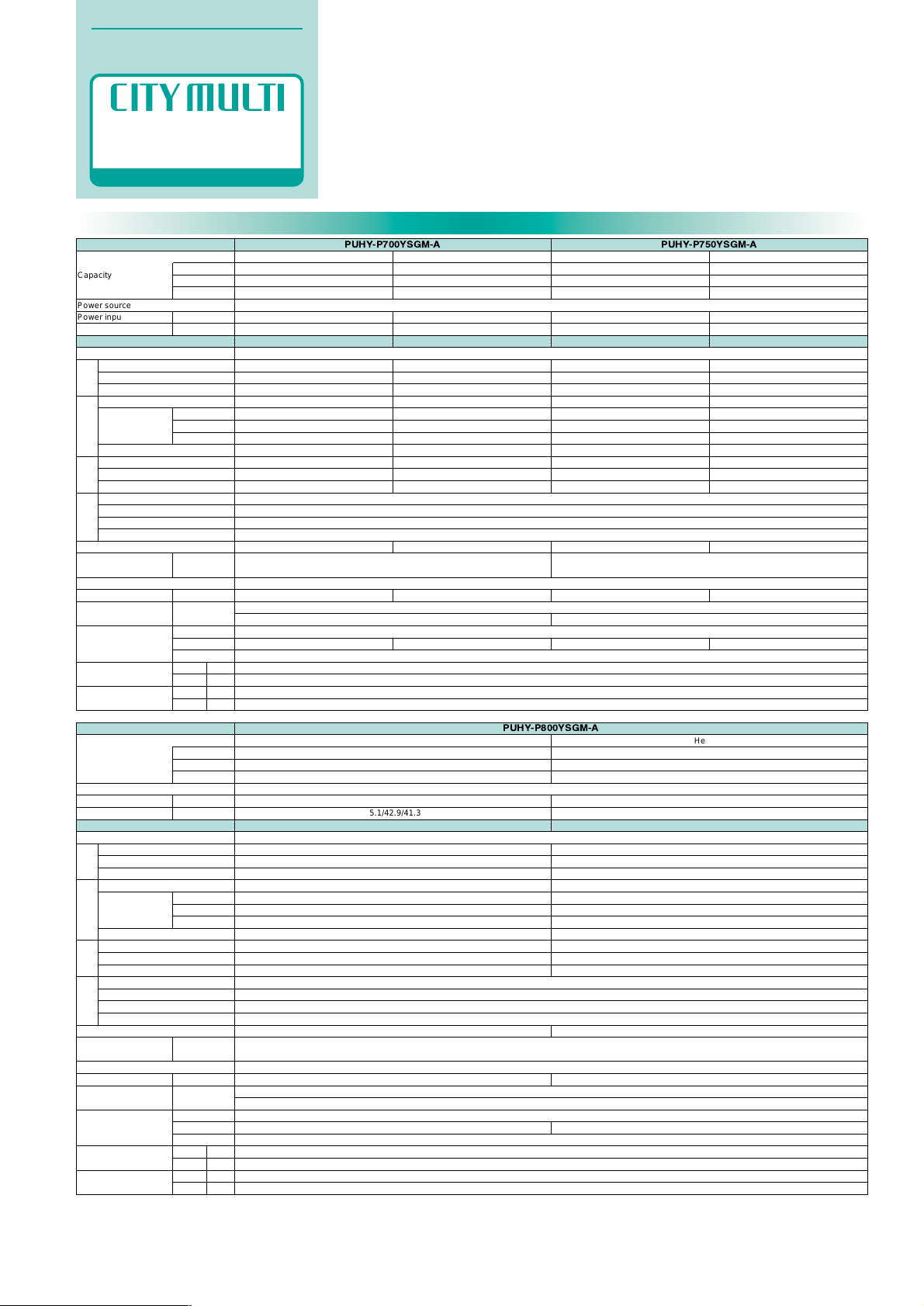
Specifications
OUTDOOR UNIT
Specifications & External Dimensions
R410A
Y SERIES
Model name
PUHY-P750YSGM-APUHY-P700YSGM-A
Capacity
Power source
Power input
Current
Composing unit model name
Heat exchanger type
Type
Starting method
Motor output (kW)
Type ✕ Quantity
Airflow rate
Motor output (kW)
High pressure protection
Inverter circuit
Compressor/fan
Gas side (main)(mm(in.))
Gas side (between Comp unit and HEX unit)(mm(in.)
Liquid side (main)(mm(in.))
Liquid side (between Comp unit and HEX unit)(mm(in.))
Refrigerant type
Noise level (dB)
(A-characteristic value) (*3)
External finish
Net weight
Indoor unit
External dimension
(mm(in.))
Temp. range of cooling
Temp. range of heating
Set
kg(lbs)
Total capacity
Model/Quantity
Height (H)
Width (W)
Depth (D)
Indoor
Outdoor
Indoor
Outdoor
m3/min
L/s
cfm
kW
A
Heating
88.0
–
300,300
21.83
36.8/35.0/33.7
Cooling
84.0
75,000
286,600
24.9
42.0/39.9/38.4
Heating
94.5
–
322,400
25.37
42.8/40.6/39.2
Cooling
78.4
70,000
267,500
21.7
36.6/34.8/33.5
PUHY-P700YGM-A (Compressor unit)
PUHN-P01YGM-A (Heat exchanger unit)
PUHY-P750YGM-A (Compressor unit)
PUHN-P01YGM-A (Heat exchanger unit)
3N ~ 380/400/415V 50/60Hz
Salt Protected Fin
φ34.93(φ1-3/8") Brazed
φ28.58(φ1-1/8") Flange / φ28.58(φ1-1/8") Brazed
φ19.05(φ3/4") Brazed + Flare
φ12.7(φ1/2") Flare / φ12.7(φ1/2") Brazed
Pre-coated galvanized sheets + powder coating (for-BS type) <MUNSEL 5Y 8/1 or similar>
50~130% of outdoor unit capacity
1840(72-1/2")
840(33-1/8")
15~24˚C (59~75˚F)
-5~43˚C (23~109˚F) 0~43˚C (32~109˚F)(When the Outdoor is at a position lower than the Indoors)
15~27˚C (59~81˚F)
-20~15.5˚C (-4~60˚F)
Inverter scroll hermetic compressor ✕ 2
Inverter
8.6 + 8.6
Propeller fan ✕ 1
240
4,000
8,476
0.64
High pressure switch 4.15MPa (601 psi)
Over-voltage and over-current protection for AC bus, Over-heat protection
Over-heat protection/Thermal switch
R410A
430(948)
1690(66-9/16")
–
–
–
Propeller fan ✕ 1
240
4,000
8,476
0.64
–
–
Thermal switch
–
155(342)
990(39")
Inverter scroll hermetic compressor ✕ 2
Inverter
9.4 + 9.4
Propeller fan ✕ 1
240
4,000
8,476
0.64
High pressure switch 4.15MPa (601 psi)
Over-voltage and over-current protection for AC bus, Over-heat protection
Over-heat protection/Thermal switch
R410A
430(948)
1690(66-9/16")
–
–
–
Propeller fan ✕ 1
240
4,000
8,476
0.64
–
–
Thermal switch
–
155(342)
990(39")
62
Models P20~P250/1~34 Models P20~P250/1~34
63
kW (*1)
kcal/h (*2)
BTU/h (*1)
Compressor
Fan
Protection
Refrigerant
piping diameter
Model name
3N ~ 380/400/415V 50/60Hz
Salt Protected Fin
φ34.93(φ1-3/8") Brazed
φ28.58(φ1-1/8") Flange / φ28.58(φ1-1/8") Brazed
φ19.05(φ3/4") Brazed + Flare
φ12.7(φ1/2") Flare / φ12.7(φ1/2") Brazed
64
Pre-coated galvanized sheets + powder coating (for-BS type) <MUNSEL 5Y 8/1 or similar>
50~130% of outdoor unit capacity
Models P20~P250/1~34
1840(72-1/2")
840(33-1/8")
15~24˚C (59~75˚F)
-5~43˚C (23~109˚F) 0~43˚C (32~109˚F)(When the Outdoor is at a position lower than the Indoors)
15~27˚C (59~81˚F)
-20~15.5˚C (-4~60˚F)
PUHY-P800YSGM-A
Cooling
90.0
80,000
307,100
26.75
45.1/42.9/41.3
Heating
100.0
–
341,200
26.9
45.4/43.1/41.5
PUHY-P800YGM-A (Compressor unit) PUHN-P01YGM-A (Heat exchanger unit)
Inverter scroll hermetic compressor ✕ 2
Inverter
10.1 + 10.1
Propeller fan ✕ 1
240
4,000
8,476
0.64
High pressure switch 4.15MPa (601 psi)
Over-voltage and over-current protection for AC bus, Over-heat protection
Over-heat protection/Thermal switch
R410A
430(948)
1690(66-9/16")
–
–
–
Propeller fan ✕ 1
240
4,000
8,476
0.64
–
–
Thermal switch
–
155(342)
990(39")
W.B.
D.B.
D.B
W.B.
Capacity
Power source
Power input
Current
Composing unit model name
Heat exchanger type
Type
Starting method
Motor output (kW)
Type ✕ Quantity
Airflow rate
Motor output (kW)
High pressure protection
Inverter circuit
Compressor/fan
Gas side (main)(mm(in.))
Gas side (between Comp unit and HEX unit)(mm(in.)
Liquid side (main)(mm(in.))
Liquid side (between Comp unit and HEX unit)(mm(in.))
Refrigerant type
Noise level (dB)
(A-characteristic value) (*3)
External finish
Net weight
Indoor unit
External dimension
(mm(in.))
Temp. range of cooling
Temp. range of heating
Set
kg(lbs)
Total capacity
Model/Quantity
Height (H)
Width (W)
Depth (D)
Indoor
Outdoor
Indoor
Outdoor
m3/min
L/s
cfm
kW
A
kW (*1)
kcal/h (*2)
BTU/h (*1)
Compressor
Fan
Protection
Refrigerant
piping diameter
W.B.
D.B.
D.B
W.B.
Note: 1. Cooling/heating capacity indicates the maximum value at operation under the following condition.
*1 (JIS Standard: JIS B8615-1) Cooling 27˚C(81˚F)DB/19˚C(66.2˚F)WB Outdoor: 35˚C(95˚F)DB
Heating Indoor: 20˚C(68˚F)DB Outdoor: 7˚C(44.6˚F)DB/6˚C(42.8˚F)WB
Pipe length: 7.5m(24-9/16Ft) Height difference: 0m
*2 Cooling Indoor: 27˚C(81˚F)DB/19.5˚C(67.1˚F)WB Outdoor: 35˚C(95˚F)DB
Pipe length: 5m(16-3/8Ft) Height difference: 0m
*3 It is measured in anechoic room.
12
Page 18
External Dimensions
OUTDOOR UNIT
Specifications & External Dimensions
R410A
Y SERIES
100
4080
10 89
3
12
159
124
161
107
11241
8825483117
78
17537 175 37
134
11
(Mounting hole)
Note1.Use the opening at the bottom of the unit
when running the power supply line from
the front or from the side of the unit.
Note2.Please refer to (2/2) for information
regarding necessary space around the
unit and foundation work.
800(mounting pitch) 800(mounting pitch)45
1840
1575
1690
45
877
840
16 16845(mounting pitch)
135
280
265
Conn. pipe(Gas)
ø34.93<Braze>
Conn. pipe(Liquid)
ø19.05<Braze+Flare>
X
X
Refrig.service valve
(Liquid pipe to HEX unit)
ø12.7<Flare>
Refrig.service valve
(Gas pipe to HEX unit)
ø28.58<Braze>
<Accessories>
• Refrigerant conn. pipe with flange (to indoor unit:Gas)....1 pc.
(Already installed on the unit)
• Refrigerant conn. pipe with flange (to HEX unit:Gas).......1 pc.
(Already installed on the unit)
• Packing for conn. pipe with flange (to indoor unit:Gas)....1 pc.
(Attached near ball valve)
• Packing for conn. pipe with flange (to HEX unit:Gas)......1 pc.
(Attached near ball valve)
• Conduit mouting plate
ø62...........................1 pc.
• Tapping screw µ4.....2 pcs.
Knockout hole
<Bottom piping hole>
ø75 Knockout hole
<Hole for power supply>
Changeable to ø62 by using
attached conduit mounting plate
<Accessory>
ø27 Knockout hole
<Bottom hole for
control wiring>
3 X 2 – 14 X 20 Oval hole
Knockout hole
<Left side piping
hole for HEX unit>
Knockout hole
<Front piping hole>
Service panel
Service panel
Knockout hole
ø27 Knockout hole
<Left side hole for
control wiring>
Air outlet
Air
inlet
Air
inlet
Refrig.service valve
(Gas pipe to indoor unit)
Refrig.service valve
(Liquid pipe to indoor unit)
Cross section X – X
Left side view Front view
Top view
877
840
2690
10
990 1690
1840
1575
265
Conn.pipe(Gas)
ø34.93<Braze>
Liquid pipe used to connect
compressor unit and HEX unit
Gas pipe used to connect
compressor unit and HEX unit
Conn.pipe(Liquid)
ø19.05<Braze+Flare>
HEX unit Compressor unit
Air outlet
Air
inlet
Air
inlet
Left side view
Front view
Unit : mm
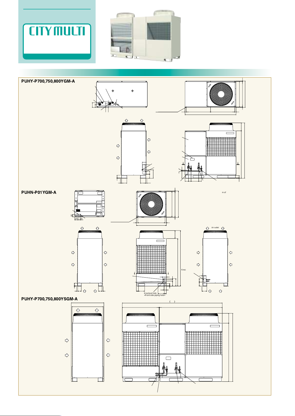
PUHY-P700,750,800YGM-A
PUHN-P01YGM-A
PUHY-P700,750,800YSGM-A
60
120
82
Knockout hole
<Front side piping hole>
Air outlet
Knockout hole
<Right side piping hole>
Air
inlet
Right side view
Air
inlet
Air
inlet
Refrig. service valve
(Liquid pipe to compressor unit)
ø12.7<Braze>
Refrig. service valve
(Gas pipe to compressor unit)
ø28.58<Braze>
Left side view
Front view
Top view
2x2-14x20 Oval hole
Air
inlet
Air
inlet
Air
inlet
Air outlet
Cross section x-x
ø27hole+rubber bush
<Hole for power supply>
(Bottom of controlbox)
ø27hole+rubber bush
<Hole for control wiring>
(Bottom of controlbox)
250
70
80
45
40
80
115
134
157
50
165
Note1.Use the opening at the bottom of the unit
when running the power supply line from
the front or from the side of the unit.
Note2.Please refer to (2/2) for information
regarding necessary space around the
unit and foundation work.
265
45
900(mounting pitch)
45
16
845(mounting pitch)
877
37 37
117
117
x
x
78
207
207
67
67
840
990
10
90
11
1840
1575
(Mounting hole)
16
13
Page 19
Specifications
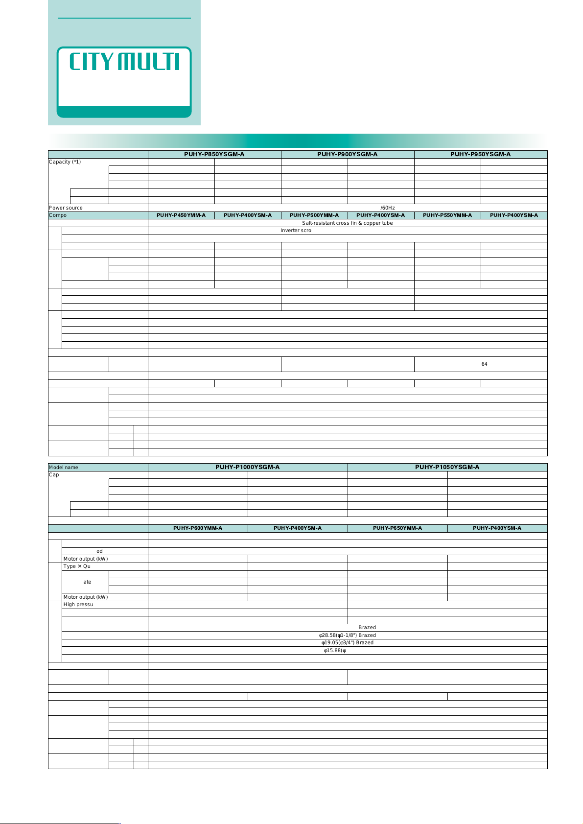
Model name
PUHY-P900YSGM-APUHY-P850YSGM-A
Capacity (*1)
Power source
Composing unit model name
Heat exchanger type
Type
Starting method
Motor output (kW)
Type ✕ Quantity
Airflow rate
Motor output (kW)
High pressure protection
Inverter circuit
Compressor/fan
Gas side (main)(mm(in.))
Gas side (between unit and distributor)(mm(in.))
Liquid side (main)(mm(in.))
Liquid side (between unit and distributor)(mm(in.))
Oil balance pipe(mm(in.))
Refrigerant type
Noise level (dB)
(A-characteristic value) (*3)
External finish
Net weight
Indoor unit
External dimension
(mm(in.))
Temp. range of cooling
Temp. range of heating
Set
kg (lbs.)
Total capacity
Model / Quantity
Height (H)
Width (W)
Depth (D)
m
3
/min
L/s
cfm
Heating
108.0
368,500
–
27.47
46.3/44.0/42.4
Cooling
101.0
344,600
90,000
26.71
45.0/42.8/41.2
Heating
113.0
385,500
–
29.10
49.1/46.6/44.9
Cooling
96.0
327,500
85,000
25.28
42.6/40.5/39.0
PUHY-P450YMM-A PUHY-P400YSM-A PUHY-P500YMM-A PUHY-P400YSM-A
3-phase 4-wire 380/400/415V 50/60Hz
Salt-resistant cross fin & copper tube
Inverter scroll hermetic comp. + Scroll hermetic comp.
Inverter + Direct
φ41.28(φ1-5/8") Brazed
φ28.58(φ1-1/8") Brazed
φ19.05(φ3/4") Brazed
φ15.88(φ5/8") Flare
φ9.52(φ3/8") Flare
R410A
Pre-coated galvanized sheets + powder coating (for-BS type) <MUNSEL 5Y 8/1 or similar>
50~130% of outdoor unit capacity
P20~P250 / 1~42
1840 (72-1/2")
1990 (78-3/8")
840 (33-1/8")
15~24˚C (59~75˚F)
-5~43˚C (23~109˚F) 0~43˚C (32~109˚F)(When the Outdoor is at a position lower than the Indoors)
15~27˚C (59~81˚F)
-20~15.5˚C (-4~60˚F)
9.4 + 5.3 / 8.5 + 5.3
Propeller fan ✕ 2
400
6,667
14,126
0.38 ✕ 2
458 (1010) 460 (1015) 458 (1010) 460 (1015) 458 (1010) 460 (1015)
High pressure switch 4.15MPa (601 psi)
Over-voltage and over-current protection for AC bus, Over-heat protection
Over-heat protection/Thermal switch
8.5 + 5.3 / 8.5 + 5.3
Propeller fan ✕ 2
400
6,667
14,126
0.38 ✕ 2
10.3 + 5.3 / 9.6 + 5.3
Propeller fan ✕ 2
400
6,667
14,126
0.38 ✕ 2
High pressure switch 4.15MPa (601 psi)
Over-voltage and over-current protection for AC bus, Over-heat protection
Over-heat protection/Thermal switch
8.5 + 5.3 / 8.5 + 5.3
Propeller fan ✕ 2
400
6,667
14,126
0.38 ✕ 2
11.2 + 5.3 / 10.9 + 5.3
Propeller fan ✕ 2
400
6,667
14,126
0.38 ✕ 2
High pressure switch 4.15MPa (601 psi)
Over-voltage and over-current protection for AC bus, Over-heat protection
Over-heat protection/Thermal switch
8.5 + 5.3 / 8.5 + 5.3
Propeller fan ✕ 2
400
6,667
14,126
0.38 ✕ 2
63/64 63/64
kW
Btu/h(*1)
kcal/h(*2)
kW
A
Power input
Current input
Compressor
Fan
Protection
Refrigerant
piping diameter
Indoor
Outdoor
Indoor
Outdoor
W.B.
D.B.
D.B.
W.B.
PUHY-P950YSGM-A
Cooling
108.0
368,500
95,000
29.23
49.3/46.8/45.1
Heating
119.5
407,700
–
30.42
51.3/48.7/47.0
PUHY-P550YMM-A PUHY-P400YSM-A
63/64
Model name
PUHY-P1050YSGM-APUHY-P1000YSGM-A
Capacity (*1)
Power source
Composing unit model name
Heat exchanger type
Type
Starting method
Motor output (kW)
Type ✕ Quantity
Airflow rate
Motor output (kW)
High pressure protection
Inverter circuit
Compressor/fan
Gas side (main)(mm(in.))
Gas side (between unit and distributor)(mm(in.))
Liquid side (main)(mm(in.))
Liquid side (between unit and distributor)(mm(in.))
Oil balance pipe(mm(in.))
Refrigerant type
Noise level (dB)
(A-characteristic value) (*3)
External finish
Net weight
Indoor unit
External dimension
(mm(in.))
Temp. range of cooling
Temp. range of heating
Set
kg (lbs.)
Total capacity
Model / Quantity
Height (H)
Width (W)
Depth (D)
m
3
/min
L/s
cfm
Heating
127.0
433,300
–
32.68
55.1/52.4/50.5
Cooling
118.0
402,600
105,000
33.48
56.5/53.6/51.7
Heating
132.0
450,300
–
34.24
57.8/54.9/52.9
Cooling
113.0
385,500
100,000
31.11
52.5/49.8/48.0
PUHY-P600YMM-A PUHY-P400YSM-A PUHY-P650YMM-A PUHY-P400YSM-A
3-phase 4-wire 380/400/415V 50/60Hz
Salt-resistant cross fin & copper tube
Inverter scroll hermetic comp. + Scroll hermetic comp.
Inverter + Direct
φ41.28(φ1-5/8") Brazed
φ28.58(φ1-1/8") Brazed
φ19.05(φ3/4") Brazed
φ15.88(φ5/8") Flare
φ9.52(φ3/8") Flare
R410A
Pre-coated galvanized sheets + powder coating (for-BS type) <MUNSEL 5Y 8/1 or similar>
50~130% of outdoor unit capacity
P20~P250 / 1~42
1840 (72-1/2")
1990 (78-3/8")
840 (33-1/8")
15~24˚C (59~75˚F)
-5~43˚C (23~109˚F) 0~43˚C (32~109˚F)(When the Outdoor is at a position lower than the Indoors)
15~27˚C (59~81˚F)
-20~15.5˚C (-4~60˚F)
11.6 + 5.3 / 11.6 + 5.3
Propeller fan ✕ 2
400
6,667
14,126
0.38 ✕ 2
458 (1010) 460 (1015) 458 (1010) 460 (1015)
High pressure switch 4.15MPa (601 psi)
Over-voltage and over-current protection for AC bus, Over-heat protection
Over-heat protection/Thermal switch
8.5 + 5.3 / 8.5 + 5.3
Propeller fan ✕ 2
400
6,667
14,126
0.38 ✕ 2
11.6 + 5.3 / 11.6 + 5.3
Propeller fan ✕ 2
400
6,667
14,126
0.38 ✕ 2
High pressure switch 4.15MPa (601 psi)
Over-voltage and over-current protection for AC bus, Over-heat protection
Over-heat protection/Thermal switch
8.5 + 5.3 / 8.5 + 5.3
Propeller fan ✕ 2
400
6,667
14,126
0.38 ✕ 2
63/64 63.5/64.5
kW
Btu/h(*1)
kcal/h(*2)
kW
A
Power input
Current input
Compressor
Fan
Protection
Refrigerant
piping diameter
Indoor
Outdoor
Indoor
Outdoor
W.B.
D.B.
D.B.
W.B.
Note: 1. Cooling/heating capacity indicates the maximum value at operation under the following condition.
*1 (JIS Standard: JIS B8615-1) Cooling 27˚C(81˚F)DB/19˚C(66.2˚F)WB Outdoor: 35˚C(95˚F)DB
Heating Indoor: 20˚C(68˚F)DB Outdoor: 7˚C(44.6˚F)DB/6˚C(42.8˚F)WB
Pipe length: 7.5m(24-9/16Ft) Height difference: 0m
*2 Cooling Indoor: 27˚C(81˚F)DB/19.5˚C(67.1˚F)WB Outdoor: 35˚C(95˚F)DB
Pipe length: 5m(16-3/8Ft) Height difference: 0m
*3 It is measured in anechoic room.
OUTDOOR UNIT
Specifications & External Dimensions
R410A
Y SERIES
14
Page 20
Specifications
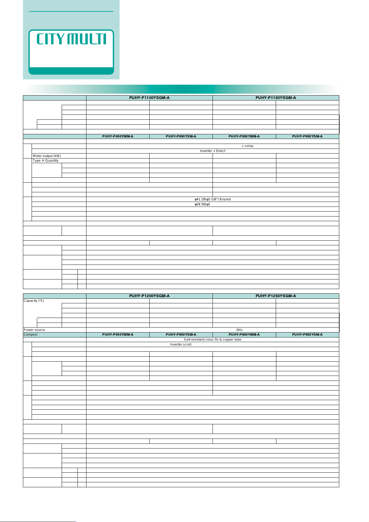
Model name
PUHY-P1250YSGM-APUHY-P1200YSGM-A
Capacity (*1)
Power source
Composing unit model name
Heat exchanger type
Type
Starting method
Motor output (kW)
Type ✕ Quantity
Airflow rate
Motor output (kW)
High pressure protection
Inverter circuit
Compressor/fan
Gas side (main)(mm(in.))
Gas side (between unit and distributor)(mm(in.))
Liquid side (main)(mm(in.))
Liquid side (between unit and distributor)(mm(in.))
Oil balance pipe(mm(in.))
Refrigerant type
Noise level (dB)
(A-characteristic value) (*3)
External finish
Net weight
Indoor unit
External dimension
(mm(in.))
Temp. range of cooling
Temp. range of heating
Set
kg (lbs.)
Total capacity
Model / Quantity
Height (H)
Width (W)
Depth (D)
m
3
/min
L/s
cfm
Heating
150.0
511,700
–
39.73
67.0/63.7/61.4
Cooling
140.0
477,600
125,000
47.56
80.2/76.2/73.5
Heating
156.5
533,900
–
42.63
71.9/68.3/65.8
Cooling
136.0
464,000
120,000
44.40
74.9/71.2/68.6
PUHY-P550YMM-A PUHY-P650YSM-A PUHY-P600YMM-A PUHY-P650YSM-A
3-phase 4-wire 380/400/415V 50/60Hz
Salt-resistant cross fin & copper tube
Inverter scroll hermetic comp. + Scroll hermetic comp.
Inverter + Direct
φ41.28(φ1-5/8") Brazed
φ28.58(φ1-1/8") Brazed
φ19.05(φ3/4") Brazed
φ15.88(φ5/8") Flare
φ9.52(φ3/8") Flare
R410A
Pre-coated galvanized sheets + powder coating (for-BS type) <MUNSEL 5Y 8/1 or similar>
50~130% of outdoor unit capacity
P20~P250 / 1~42
1840 (72-1/2")
1990 (78-3/8")
840 (33-1/8")
15~24˚C (59~75˚F)
-5~43˚C (23~109˚F) 0~43˚C (32~109˚F)(When the Outdoor is at a position lower than the Indoors)
15~27˚C (59~81˚F)
-20~15.5˚C (-4~60˚F)
11.2 + 5.3 / 10.9 + 5.3
Propeller fan ✕ 2
400
6,667
14,126
0.38 ✕ 2
458 (1010) 460 (1015) 458 (1010) 460 (1015)
High pressure switch 4.15MPa (601 psi)
Over-voltage and over-current protection for AC bus, Over-heat protection
Over-heat protection/Thermal switch
11.6 + 5.3 / 11.6 + 5.3
Propeller fan ✕ 2
400
6,667
14,126
0.38 ✕ 2
11.6 + 5.3 / 11.6 + 5.3
Propeller fan ✕ 2
400
6,667
14,126
0.38 ✕ 2
High pressure switch 4.15MPa (601 psi)
Over-voltage and over-current protection for AC bus, Over-heat protection
Over-heat protection/Thermal switch
11.6 + 5.3 / 11.6 + 5.3
Propeller fan ✕ 2
400
6,667
14,126
0.38 ✕ 2
64/65 65/65.5
kW
Btu/h(*1)
kcal/h(*2)
kW
A
Power input
Current input
Compressor
Fan
Protection
Refrigerant
piping diameter
Indoor
Outdoor
Indoor
Outdoor
W.B.
D.B.
D.B.
W.B.
Model name
PUHY-P1150YSGM-APUHY-P1100YSGM-A
Capacity (*1)
Power source
Composing unit model name
Heat exchanger type
Type
Starting method
Motor output (kW)
Type ✕ Quantity
Airflow rate
Motor output (kW)
High pressure protection
Inverter circuit
Compressor/fan
Gas side (main)(mm(in.))
Gas side (between unit and distributor)(mm(in.))
Liquid side (main)(mm(in.))
Liquid side (between unit and distributor)(mm(in.))
Oil balance pipe(mm(in.))
Refrigerant type
Noise level (dB)
(A-characteristic value) (*3)
External finish
Net weight
Indoor unit
External dimension
(mm(in.))
Temp. range of cooling
Temp. range of heating
Set
kg (lbs.)
Total capacity
Model / Quantity
Height (H)
Width (W)
Depth (D)
m
3
/min
L/s
cfm
Heating
140.0
477,600
–
36.93
62.3/59.2/57.0
Cooling
130.0
443,500
115,000
39.96
67.4/64.0/61.7
Heating
145.0
494,700
–
38.46
64.9/61.6/59.4
Cooling
124.0
423,000
110,000
36.39
61.4/58.3/56.2
PUHY-P450YMM-A PUHY-P650YSM-A PUHY-P500YMM-A PUHY-P650YSM-A
3-phase 4-wire 380/400/415V 50/60Hz
Salt-resistant cross fin & copper tube
Inverter scroll hermetic comp. + Scroll hermetic comp.
Inverter + Direct
φ41.28(φ1-5/8") Brazed
φ28.58(φ1-1/8") Brazed
φ19.05(φ3/4") Brazed
φ15.88(φ5/8") Flare
φ9.52(φ3/8") Flare
R410A
Pre-coated galvanized sheets + powder coating (for-BS type) <MUNSEL 5Y 8/1 or similar>
50~130% of outdoor unit capacity
P20~P250 / 1~42
1840 (72-1/2")
1990 (78-3/8")
840 (33-1/8")
15~24˚C (59~75˚F)
-5~43˚C (23~109˚F) 0~43˚C (32~109˚F)(When the Outdoor is at a position lower than the Indoors)
15~27˚C (59~81˚F)
-20~15.5˚C (-4~60˚F)
9.4 + 5.3 / 8.5 + 5.3
Propeller fan ✕ 2
400
6,667
14,126
0.38 ✕ 2
458 (1010) 460 (1015) 458 (1010) 460 (1015)
High pressure switch 4.15MPa (601 psi)
Over-voltage and over-current protection for AC bus, Over-heat protection
Over-heat protection/Thermal switch
11.6 + 5.3 / 11.6 + 5.3
Propeller fan ✕ 2
400
6,667
14,126
0.38 ✕ 2
10.3 + 5.3 / 9.6 + 5.3
Propeller fan ✕ 2
400
6,667
14,126
0.38 ✕ 2
High pressure switch 4.15MPa (601 psi)
Over-voltage and over-current protection for AC bus, Over-heat protection
Over-heat protection/Thermal switch
11.6 + 5.3 / 11.6 + 5.3
Propeller fan ✕ 2
400
6,667
14,126
0.38 ✕ 2
64/65 64/65
kW
Btu/h(*1)
kcal/h(*2)
kW
A
Power input
Current input
Compressor
Fan
Protection
Refrigerant
piping diameter
Indoor
Outdoor
Indoor
Outdoor
W.B.
D.B.
D.B.
W.B.
Note: 1. Cooling/heating capacity indicates the maximum value at operation under the following condition.
*1 (JIS Standard: JIS B8615-1) Cooling 27˚C(81˚F)DB/19˚C(66.2˚F)WB Outdoor: 35˚C(95˚F)DB
Heating Indoor: 20˚C(68˚F)DB Outdoor: 7˚C(44.6˚F)DB/6˚C(42.8˚F)WB
Pipe length: 7.5m(24-9/16Ft) Height difference: 0m
*2 Cooling Indoor: 27˚C(81˚F)DB/19.5˚C(67.1˚F)WB Outdoor: 35˚C(95˚F)DB
Pipe length: 5m(16-3/8Ft) Height difference: 0m
*3 It is measured in anechoic room.
OUTDOOR UNIT
Specifications & External Dimensions
R410A
Y SERIES
15
Page 21
External Dimensions
OUTDOOR UNIT
Specifications & External Dimensions
R410A
Y SERIES
145
76
217
194
285
163
100
48
80
Note1.Use the opening at the bottom of the unit
when running the power supply line from
the front or from the side of the unit.
Note2.Please refer to (2/2) for information
regarding necessary spacing around the
unit and foundation work.
Note3.This unit is used in combination with
a sub unit.(Refer to Drawing No.W656886
Outline Drawing of Outdoor Unit set)
Top view
(Mounting hole)
78
265
3✕2–14✕20 Oval hole
65 160
57
80
768
1000
553
494
70 20
280
100134
37
11511537
10 89
80 40
135
67 160
235
20520568 68
11
1575
1840
950(mounting pitch)
845(mounting pitch) 1616
840
877
950(mounting pitch) 45
1990
45
ø53
12 5
Conn. pipe
<To sub unit:Gas>
ø28.58<Brazed>
Knockout hole
<Bottom piping hole>
Front view
Refrig.service valve
<Gas>
Refrig.service valve
<Gas>
Knockout hole
<Front piping
hole>
Service panel
Knockout hole
Knockout hole
<Left piping hole>
ø27 Knockout hole
<Left side hole for
control wiring>
Left side view
Cross section Y–Y
Air
inlet
Air
inlet
Air outlet
ø62 Knockout hole
<Hole for power supply>
Changeable to ø46,ø53 by using attached
conduit mounting plate <Accessory>
Cross section X–X
ø27 Knockout hole
<Bottom hole for control wiring>
Refrig.service valve
<Liquid>
Refrig.service valve
<Liquid>
<Accessories>
• Refrigerant(Gas) conn.pipe....1pc.
(Already installed on the unit)
• Packing for conn.pipe....1pc.
(Attached near the ball valve)
• Conduit mounting plate
ø53, ø46...1pc.Each
• Tapping screw M4....2pcs.
Service valve
<Oil balance>
ø9.52<Flare>
Y
YY
Y
Conn. pipe<Liquid>
ø15.88<Flare>
48
45245
92
76
285
62100
20568
16067
163
217
235
80
Note1.Use the opening at the bottom of the unit
when running the power supply line from
the front or from the side of the unit.
Note2.Please refer to (2/2) for information
regarding necessary spacing around the
unit and foundation work.
Note3.This unit is used in combination with
a main unit.(Refer to Drawing No.W656886
Outline Drawing of Outdoor Unit set)
78
265
3✕2–14✕20 Oval hole
65
160
57 80
768
1000
553
494
70 20
280
100134
3711511537
10 89
80 40
135
205 68
11
1575
1840
Top view
(Mounting hole)
950(mounting pitch)
845(mounting pitch)
16
16
840
877
950(mounting pitch) 45
1990
45
ø53
12 5
Knockout hole
<Bottom piping hole>
<Accessories>
• Gas distributor....1pc.
(Already installed on the unit)
• Liquid distributor....1pc.
• Packing for conn. pipe....1pc.
(Attached near the gas distributor)
• Conduit mounting plate
ø53, ø46....1pc.Each
• Tapping screw M4....2pcs.
• Conn. pipe(Gas)....2pcs.
Service valve<Oil balance>
ø9.52<Flare>
Conn.pipe<Liquid>
ø15.88<Flare>
Conn.pipe
<To main unit:Gas>
ø28.58<Brazed>
Conn.pipe <Gas>
ø41.28<Brazed>
Refrig.service valve
<Liquid>
Refrig.service valve
<Gas>
Y
Y
Y
Y
Cross section Y–Y
ø62 Knockout hole
<Hole for power supply>
Changeable to ø46,ø53 by using attached
conduit mounting plate <Accessory>
ø27 Knockout hole
<Bottom hole for control wiring>
Cross section X–X
Knockout hole
<Left piping hole>
Left side view
Air
inlet
Air
inlet
ø27 Knockout hole
<Left side hole for
control wiring>
Air outlet
Front view
Knockout hole
Service panel
Knockout hole
<Front piping hole>
1990101990
840
877
Sub unit
Main unit
Indoor units~
Distributor
Liquid
Liquid
Liquid
Gas
Gas
Gas
Distributor~
Main unit
a
b
c
d
e
f
g
Distributor~
Sub unit
Oil balance pipe
PUHY-P850YSGM-A
PUHY-P900YSGM-A
PUHY-P450YMM-A PUHY-P500YMM-A
PUHY-P550YMM-A
PUHY-P600YMM-A
PUHY-P950YSGM-A
PUHY-P400YSM-A
PUHY-P1000YSGM-A
ø19.05
ø15.88
ø41.28
ø28.58
ø15.88
ø28.58
ø9.52
PUHY-P1050YSGM-A
PUHY-P650YMM-A
PUHY-P1100YSGM-A
PUHY-P450YMM-A
PUHY-P1150YSGM-A
PUHY-P500YMM-A
PUHY-P1200YSGM-A
PUHY-P650YSM-A
PUHY-P550YMM-A
PUHY-P600YMM-A
PUHY-P1250YSGM-A
f
e
g
b
a
d
c
Left side view
c
d
Front view
a
Indoor units
Distributor(Liquid)
Distributor(Gas)
Air outlet
Air
inlet
Air
inlet
Sub unit
Main unit
Note1.Pipe size is as show in the table on the left.
PUHY-P450,500,550,
600,650YMM-A
PUHY-P450,650YSM-A
PUHY-P850,900,950,
1000,1050,1100,1150,
1200,1250YSGM-A
16
Page 22
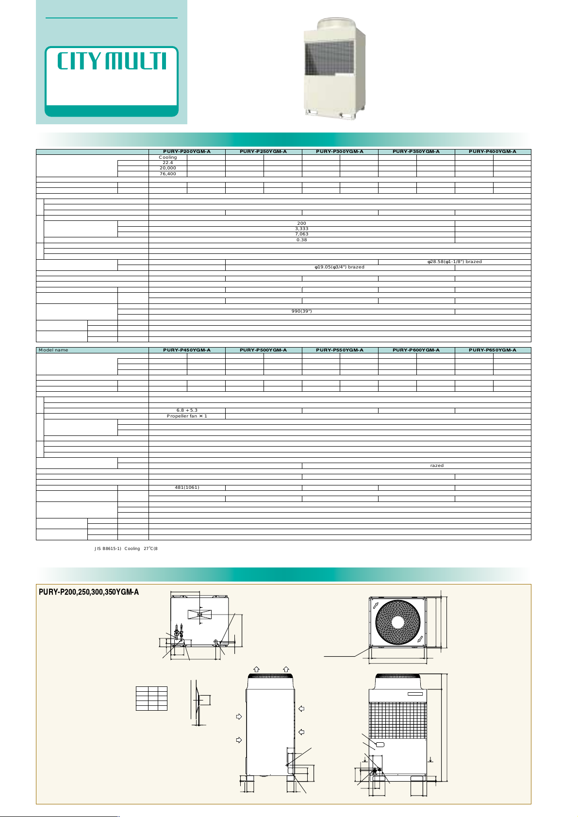
Specifications
Model name
4.7
φ19.05(φ3/4") brazed
φ15.88(φ5/8") brazed
56
236(521)
Models P20~P250/1~15
6.7
57
251(554)
Models P20~P250/1~16
8.0
59
251(554)
Models P20~P250/1~16
9.6
60
251(554)
Models P20~P250/1~20
9.7
240
4,000
8,476
0.64
φ22.2(φ7/8") brazed
61
291(642)
Models P20~P250/1~24
1290(50-13/16")
3N ~ 380/400/415V 50/60Hz
Salt Protected Fin
Inverter scroll hermetic compressor
Inverter
Propeller fan ✕ 1
High pressure switch 4.15MPa (601 psi)
Over-voltage and over-current protection for AC bus, Over-heat protection
Over-heat protection/Thermal switch
R410A
Pre-coated galvanized sheets + powder coating (for-BS type) <MUNSEL 5Y 8/1 or similar>
50~150% of outdoor unit capacity
1840(72-1/2")
840(33-1/8")
15~24˚C (59~75˚F)
-5~43˚C (23~109˚F) 0~43˚C (32~109˚F)(When the Outdoor is at a position lower than the Indoors)
15~27˚C (59~81˚F)
-20~15.5˚C (-4~60˚F)
φ22.2(φ7/8") brazed
Capacity
Power source
Power input
Current
Heat exchanger type
Type
Starting method
Motor output (kW)
Type ✕ Quantity
Airflow rate
Motor output (kW)
High pressure protection
Inverter circuit
Compressor/fan
Refrigerant piping diameter
(mm(in.))
Refrigerant type
Noise level (dB) (A-characteristic value) (*3)
External finish
Net weight
Indoor unit
External dimension (mm(in.))
Temp. range of
cooling
Temp. range of
heating
Gas side
Liquid side
m3/min
L/s
cfm
kW
A
kW (*1)
kcal/h (*2)
BTU/h (*1)
kg (lbs)
Total capacity
Model/Quantity
Height (H)
Width (W)
Depth (D)
W.B.
D.B.
D.B
W.B.
Indoor
Outdoor
Indoor
Outdoor
Compressor
Fan
Protection device
PURY-P200YGM-A PURY-P250YGM-A PURY-P300YGM-A PURY-P350YGM-A PURY-P400YGM-A
200
3,333
7,063
0.38
990(39")
Model name
6.8 + 5.3
Propeller fan ✕ 1
481(1061)
Models P20~P250/1~24
8.2 + 5.3
481(1061)
Models P20~P250/1~24
9.3 + 5.3
481(1061)
Models P20~P250/1~24
10.1 + 5.3
481(1061)
Models P20~P250/1~32
10.9 + 5.3
62/62.5 (50Hz/60Hz)
481(1061)
Models P20~P250/1~32
3N ~ 380/400/415V 50/60Hz
Salt Protected Fin
Inverter scroll hermetic compressor
Inverter
400
6,667
14,126
0.38 ✕ 2
High pressure switch 4.15MPa (601 psi)
Over-voltage and over-current protection for AC bus, Over-heat protection
Over-heat protection/Thermal switch
φ28.58(φ1-1/8") brazed
R410A
Pre-coated galvanized sheets + powder coating (for-BS type) <MUNSEL 5Y 8/1 or similar>
50~150% of outdoor unit capacity
1840(72-1/2")
1990(78-3/8")
840(33-1/8")
15~24˚C (59~75˚F)
-5~43˚C (23~109˚F) 0~43˚C (32~109˚F)(When the Outdoor is at a position lower than the Indoors)
15~27˚C (59~81˚F)
-20~15.5˚C (-4~60˚F)
PURY-P450YGM-A PURY-P500YGM-A PURY-P550YGM-A PURY-P600YGM-A PURY-P650YGM-A
φ22.2(φ7/8") brazed
60/61 (50Hz/60Hz)
61/62 (50Hz/60Hz)
φ28.58(φ1-1/8") brazed
φ19.05(φ3/4") brazed
φ28.58(φ1-1/8") brazed
Cooling
22.4
20,000
76,400
6.14
10.3/9.8/9.4
Heating
25.0
–
85,300
5.98
10.0/9.5/9.2
Cooling
50.0
45,000
170,600
13.61
22.9/21.8/21.0
Heating
56.0
–
191,100
13.86
23.3/22.2/21.4
Cooling
56.0
50,000
191,100
15.59
26.3/25.0/24.0
Heating
63.0
–
215,000
15.89
26.8/25.4/24.5
Cooling
63.0
55,000
215,000
17.08
28.8/27.3/26.4
Heating
67.0
–
228,600
16.37
27.6/26.2/25.3
Cooling
67.4
60,000
230,000
17.59
29.6/28.2/27.1
Heating
75.0
–
255,900
17.73
29.9/28.4/27.4
Cooling
73.0
65,000
249,100
19.65
33.1/31.5/30.3
Heating
81.5
–
278,100
19.82
33.4/31.7/30.6
Cooling
28.0
25,000
95,500
7.72
13.0/12.3/11.9
Heating
31.5
–
107,500
7.62
12.8/12.2/11.7
Cooling
33.5
30,000
114,300
9.57
16.1/15.3/14.7
Heating
37.5
–
128,000
9.1
15.3/14.5/14.0
Cooling
40.0
35,000
136,500
11.39
19.2/18.2/17.6
Heating
45.0
–
153,500
11.02
18.6/17.6/17.0
Cooling
45.0
40,000
153,500
13.42
22.6/21.5/20.7
Heating
50.0
–
170,600
12.43
20.9/19.9/19.2
External Dimensions
B
A
83100
15184
3711711737
768
65
160
57 80
494
553
134
280
135
80 40
10
90
100
80
70 20
265
45
900(bolt hole)
45
16
845(bolt hole)
877
X
X
78
67
207
20767
840
16
990
67
160
235
11
1840
1575
512
ø53
Conn. pipe
(low pressure)
200:ø19.05<brazed>
250:ø22.2 <brazed>
300:ø22.2 <brazed>
350:ø28.58<brazed>
Conn. pipe
(high pressure)
200:ø15.88<brazed>
250:ø19.05<brazed>
300:ø19.05<brazed>
350:ø19.05<brazed>
Model
200
250
300
350
AB
145 115
135
145
120
135 120
120
Knockout hole
<Front piping
hole>
Cross section X–X
Cross section Y–Y
[Accessories]
• Refrigerant (high pressure) conn. pipe..............1pc.
• Refrigerant (low pressure) conn. pipe................1pc.
(The connecting pipe has been fixed with the unit)
• Packing for conn. low pressure pipe..................1pc.
(Attached near the ball valve)
• Conduit mouting plate
ø33, ø27............................Each 1pc.
• Tapping screw M4.....................1pcs.
Refrig. service
valve(low pressure)
<Flange>
Knockout hole
<Left piping hole>
ø27 Knockout hole
<Left side hole for
the control wiring>
Refrig. service
valve (high pressure)
<Flare>
Service panel
Knockout hole
Left side view
Front view
Plane view
2X2-14X20 0val hole
Knockout hole
<Bottom piping hole>
ø27 Knockout hole
<Bottom hole for the
control wiring>
ø62 Knockout hole <Hole for the power supply>
Changeable to ø27,ø33 by using
attached conduit mounting plate <Accessory>
Air
inlet
Air
inlet
Air outlet
Y
Y
Unit : mm
PURY-P200,250,300,350YGM-A
Propeller fan ✕ 2
Note: 1. Cooling/heating capacity indicates the maximum value at operation under the following condition.
*1 (JIS Standard: JIS B8615-1) Cooling 27˚C(81˚F)DB/19˚C(66.2˚F)WB Outdoor: 35˚C(95˚F)DB
Heating Indoor: 20˚C(68˚F)DB Outdoor: 7˚C(44.6˚F)DB/6˚C(42.8˚F)WB
Pipe length: 7.5m(24-9/16Ft) Height difference: 0m
*2 Cooling Indoor: 27˚C(81˚F)DB/19.5˚C(67.1˚F)WB Outdoor: 35˚C(95˚F)DB
Pipe length: 5m(16-3/8Ft) Height difference: 0m
*3 It is measured in anechoic room.
OUTDOOR UNIT
Specifications & External Dimensions
R410A
R2 SERIES
17
Page 23

External Dimensions
145
90
950(bolt hole)
845(bolt hole)
1616
840
877
950(bolt hole)
45
1990
45
65
160
57 80
768
1000
553
145
494
70
20
80
265
78
80
67 160
280
100134
37
11511537
10 89
40
135
44
235
100
20529026026029020568
68
11
1575
1840
150
ø53
12 5
Conn. pipe
(high pressure)
450:ø22.2 <brazed>
500:ø22.2 <brazed>
550:ø28.58<brazed>
600:ø28.58<brazed>
650:ø28.58<brazed>
Conn. pipe
(low pressure)
ø28.58<brazed>
X
X
3X2-14X20 Oval hole
Plane view
Refrig. service
valve(low pressure)
<Flange>
Refrig. service
valve (high pressure)
<Flange>
Knockout hole
<Front piping hole>
Service panel
Left side view
Knockout hole
<Left piping hole>
ø27 Knockout hole
<Left side hole for
the control wiring>
Knockout hole
Cross section X–X
Cross section Y–Y
Air outlet
Air
inlet
Air
inlet
[Accessories]
• Refrigerant (high pressure) conn. pipe.......... 1 pc.
(The connecting pipe has been fixed with the unit)
• Refrigerant (low pressure) conn. pipe............ 1 pc.
(The connecting pipe has been fixed with the unit)
• Packing for conn. high pressure pipe............. 1 pc.
(Attached near the ball valve)
• Packing for conn. low pressure pipe.............. 1 pc.
(Attached near the ball valve)
• Conduit mouting plate
ø53, ø46..................... Each 1 pc.
• Tapping screw M4.............. 2 pcs.
Front view
ø27 Knockout hole
<Bottom hole for the
control wiring>
ø62 Knockout hole
<Hole for the power supply>
Changeable to ø46,ø53 by using
attached conduit mounting plate <Accessory>
Knockout hole
<Bottom piping hole>
Y
Y
Y
Y
Unit : mm
PURY-P400YGM-A
PURY-P450,500,550,600,650YGM-A
83100
15184
81
1200(bolt hole)
45
16
845(bolt hole)
45
16
877
1290
840
160
8057
1068
65
145
503
644
70 20
80
X
X
160
68355
11 78
1575 265
1840
355
68
235
67
135
40
89
10
37 115 115
37
134 100
280
80
512
ø53
Conn. pipe
(high pressure)
ø22.2 <brazed>
Conn. pipe
(low pressure)
ø28.58<brazed>
[Accessories]
• Refrigerant (high pressure) conn. pipe........... 1pc.
(The connecting pipe has been fixed with the unit)
• Refrigerant (low pressure) conn. pipe............. 1pc.
(The connecting pipe has been fixed with the unit)
• Packing for conn. high pressure pipe.............. 1pc.
(Attached near the ball valve)
• Packing for conn. low pressure pipe............... 1pc.
(Attached near the ball valve)
• Conduit mouting plate
ø53, ø46................... Each 1pc.
• Tapping screw M4............ 2pcs.
Left side view Front view
Plane view
Refrig. service
valve(low pressure)
<Flange>
Knockout hole
<Left piping hole>
Knockout hole
<Front piping
hole>
ø27 Knockout hole
<Left side hole for
the control wiring>
Refrig. service
valve (high pressure)
<Flange>
Service panel
Knockout hole
Cross section X–X
Cross section Y–Y
Air
inlet
Air
inlet
Air outlet
2X2-14X20 Oval hole
ø27 Knockout hole
<Bottom hole for the
control wiring>
ø62 Knockout hole
<Hole for the power supply>
Changeable to ø46,ø53 by using
attached conduit mounting plate <Accessory>
Knockout hole
<Bottom piping hole>
Y
Y
OUTDOOR UNIT
Specifications & External Dimensions
R410A
R2 SERIES
18
Page 24

HEAT SOURCE UNIT
Specifications & External Dimensions
R410A
WY SERIES
3N~380/400/415V 50/60Hz
Inverter scroll hermetic compressor
Galvanized sheets
High pressure switch 4.15 MPa (601psi)
Over-heat protection
50%~130% of heat sourse unit capacity
Over-voltage and over-current protection for AC bus, Over-heat protection
1,800(70-7/8")
550(21-
11
/16")
990(39") 1,980(78")
Indoor:15˚CWB~24˚CWB
Water :10˚C~45˚C
Indoor:15˚CDB~27CDB
Water :10˚C~45˚C
Indoor:15˚CWB~24˚CWB
Water :10˚C~45˚C
Indoor:15˚CDB~27˚CDB
Water :10˚C~45˚C
Indoor:15˚CWB~24˚CWB
Water :10˚C~45˚C
Indoor:15˚CDB~27˚CDB
Water :10˚C~45˚C
Indoor:15˚CDB~27˚CDB
Water :10˚C~45˚C
Indoor:15˚CWB~24˚CWB
Water :10˚C~45˚C
External Dimensions
PQHY-P200,P250YGM-A
Model name
Capacity
Power source
Power input
Current
Type
Motor output
Type
Water volume in the coil
Volume
Pressure drop
Refrigerant
External finish
External dimension
High pressure protection
Compressor
Inverter
Refrigerant piping diameter
Total capacity
Model / Quantity
Noise level
Net weight
Operating temperature range
kW
BTU/h
kW
A
kW
R
m
3
/h
cfh
kPa
dB<A>
kg(lbs.)
Compressor
Heat
exchanger
Circulating
water
Protection
devices
Indoor
unit
Gas/Liquid
PQHY-P200YGM-A
Cooling
22.4
76,400
4.79
8.0/7.6/7.4
Heating
25.0
85,300
4.69
7.9/7.5/7.2
5.0
Double coil
9.5
4.56
161
16.5
R410A
ø9.52 flare / ø19.05 Flange
Model P20~250/1~13
46
272(600)
PQHY-P250YGM-A
Cooling
28.0
95,500
5.95
10.0/9.5/9.1
Heating
31.5
107,500
5.80
9.7/9.3/8.9
6.0
Double coil
10.5
5.76
203
19.5
R410A
ø9.52 flare /ø22.2 Flange
PQHY-P400YSGM-A
Cooling
45.0
153,500
11.35
19.1/18.2/17.5
Heating
50.0
170,600
11.01
18.5/17.6/17.0
9.7
Double coil
17.5
9.12
322
16.5
R410A
ø12.7 flare / ø28.58 Flange
Model P20~250/1~22
50
208+244(459+538)
PQHY-P500YSGM-A
Cooling
56.0
191,100
15.06
25.4/24.2/23.3
Heating
63.0
215,000
13.60
22.9/21.8/21.0
11.6
Double coil
19.5
11.52
407
19.5
R410A
ø15.88 flare / ø28.58 Flange
Model P20~250/1~16
47
275(607)
Model P20~250/1~24
53
208+248(459+547)
Height(H)
Width(W)
Depth(D)
mm(in.)
1.Cooling/Heating capacity indicates the maximum value at operation under the following condition.
Cooling Indoor:27
˚C(80.6˚F)DB/19˚CWB Water temperature: 30˚C(80˚F)
Heating Indoor:20˚C(68˚F)DB Water temperature:20˚C(68˚F)
Pipe length:7.5m(24-
9
/16Ft) Height difference:0m
2.The ambient temperature of heat source unit has to be kept below 40˚C(104˚F)(dry bulb).
The ambient relative humidity of heat source unit has to be kept below 80%.
3.This unit can not be installed in the outdoor.(No protection against the weather.)
4.It is measured in anechoic room.
5.When the total capacity of indoor units exceeds 130% of heat source units capacity,
the operating temperature range of circulating water is 15˚C(59˚F)~45˚C(113˚F)
Note:
Specifications
A
P250 1299
1289
B
P200A1346
1346
2X2-14X20 Oval hole
ø70<piping hole>
ø40 <piping hole>
ø38 Knockout hole
<Hole for the power supply>
ø38 Knockout hole
<Hole for the power supply>
ø62 Knockout hole
<piping hole>
ø38 Knockout hole
<piping hole>
ø27 Knockout hole
<Hole for the control wiring>
ø38 Knockout hole
<Hole for the power
supply>
ø27 Knockout hole
<Hole for the control
wiring>
ø27 Knockout hole
<Hole for the control wiring>
(1800)
B
95
126
1590
1772
16
1579
140
126
415
255
94
50
415
255
154
69
939
879
182
568
495
318
127
256
206
123
990
45 45
900(mounting pitch)
602
570(mounting pitch)
550
1626
1598
1497
924
1397
78
108
495
(mounting hole)
Water inlet
(PT1 1/2 screw)
Note 1
Water outlet
(PT1 1/2 screw)
Water outlet
(PT1 1/2 screw)
Water inlet
(PT1 1/2 screw)
Note 1
Left side view Front view Right side view Rear view
Plane view
Conn. pipe<liquid>
200:ø9.52<flare>
250:ø9.52<flare>
Conn. pipe<gas>
200:ø19.05<brazed>
250:ø22.2<brazed>
Refrig. service valve<liquid>
Refrig. service valve<gas>
Knockout hole
Drain
(PT1 screw)
Drain(PT1 screw)
Note 2
400
400
600
Fig. A
Piping space
(left side pipe)
Piping space
(upside pipe)
Piping space
(left side pipe)
Plane view
Front view
Service space
(front side)
[Accessories]
• Refrigerant <gas> conn. pipe........... 1pc.
• Packing for conn. pipe.................... 1pc.
(Attached near the ball valve)
• Bushing......................................... 2pcs.
Model
Note 1. At the time of product shipment, the front side piping specification serves as the local drainage connection. When connecting on the rear side, please remove the rear side plug
sealing corks, and attach to a front side. Ensure there is no leak after the attachment has been fitted.
2. Take notice of service space as Fig. A (In case of single setting, 600mm or more of back space as front space makes easier access when servicing the unit from the rear side.)
3. In case the temperature around the heat source unit has possibility to drop under 0°C, be careful for the following point to prevent the pipe burst by the water pipe freeze-up.
• Circulate the water all the time even if the heat source unit is not in operation.
• Drain the water from inside of the heat source unit when the heat source unit will not operate for a long term.
19
Page 25

External Dimensions
PQHY-P400,P500YSGM-A
HEAT SOURCE UNIT
Specifications & External Dimensions
R410A
WY SERIES
ø70<piping hole>
2X2-14X20 Oval hole
2X2-14X20 Oval hole
400
600
400
233
143
126
(1800)
624
585
10
990
131
76
719
126
418
272
16
602
570(mounting pitch)
550
1590
127
182
1772
418
272
45
900(mounting pitch)
990
660
1599
950
69
154
568
318
939
879
45
900(mounting pitch)
78
108
1990
ø56
<piping hole>
(mounting hole)
(mounting hole)
Fig. A
Front view
Piping space
(left side pipe)
Piping space
(upside pipe)
Piping space
(left side pipe)
Plane view
Service space
(front side)
ø38 Knockout hole
<Hole for the power supply>
ø27 Knockout hole
<Hole for the control wiring>
Water inlet
(PT2 screw)
Water outlet
(PT2 screw)
Water outlet
(PT2 screw)
Water inlet
(PT2 screw)
Plane view
Knockout hole
<piping hole>
Left side view
Conn. pipe<gas>
P400:ø28.58<brazed>
P500:ø28.58<brazed>
Conn. pipe<liquid>
P400:ø12.7<braze+flare>
P500:ø15.88<braze+flare>
Locally piping
ø9.52 <braze+flare>
ø19.05 <braze+flare>
ø25.4 <flange,brazed>
Conn.pipe between HEX unit
and Compressor unit
(Extension code for water heat source)
Control signal wire
<connector,locally connected>
ø27 Knockout hole
<Hole for the control
wiring>
ø38 Knockout hole
<Hole for the power
supply>
Compressor unit
Front view Right side view
Heat exchanger unit
Refrig. service valve
<liquid>
Refrig. service
valve<gas>
Knockout hole
Drain
(PT1 screw)
Drain
(PT1 screw)
[Accessories]
• Refrigerant <gas> conn.pipe.............................................. 1pc.
(The connecting pipe is fixed with the unit)
• Refrigerant <liquid> conn.pipe........................................... 1pc.
(Packaged in the accessory kit)
• Refrigerant conn.pipe between HEX unit and Compressor unit
ø9.52................................................................................ 2pcs.
(Packaged in the accessory kit)
ø19.05.............................................................................. 2pcs.
(Packaged in the accessory kit)
ø25.4................................................................................ 2pcs.
(Packaged in the accessory kit : HEX unit)
(The connecting pipe is fixed with the unit : Compressor unit)
• Packing for conn.pipe....................................................... 4pcs.
(Attached near the ball valve)
• Bushing............................................................................. 6pcs.
• Extension code for water heat source............................... 1set
Note 1. At the time of product shipment, the front side piping specification serves as the local drainage connection. When connecting on the rear side, please remove the rear side plug sealing corks, and attach to a front side. Ensure
there is no leak after the attachment has been fitted.
2. Take notice of service space as Fig. A (In case of single setting, 600mm or more of back space as front space makes easier access when servicing the unit from the rear side.)
3. In case the temperature around the heat source unit has possibility to drop under 0°C, be careful for the following point to prevent the pipe burst by the water pipe freeze-up.
• Circulate the water all the time even if the heat source unit is not in operation.
• Drain the water from inside of the heat source unit when the heat source unit will not operate for a long term.
4. Use the extension code for water heat source (option) to take space (more than 2m) between HEX unit Compressor unit.
20
Page 26

Specifications
3N~380/400/415V 50/60Hz
Inverter scroll hermetic compressor
High pressure switch 4.15 MPa (601psi)
Over-heat protection
50%~150% of heat sourse unit capacity
Over-voltage and over-current protection for AC bus, Over-heat protection
Galvanized sheets
External Dimensions
PQRY-P200,P250YGM-A
HEAT SOURCE UNIT
Specifications & External Dimensions
R410A
WR2 SERIES
Model name
Capacity
Power source
Power input
Current
Type
Motor output
Type
Water volume in the coil
Volume
Pressure drop
Refrigerant
External finish
External dimension
High pressure protection
Compressor
Inverter
Refrigerant piping diameter
Total capacity
Model / Quantity
Noise level
Net weight
Operating temperature range
kW
BTU/h
kW
A
kW
R
m
3
/h
cfh
kPa
dB<A>
kg(lbs)
Compressor
Heat
exchanger
Circulating
water
Protection
devices
indoor
unit
gas / Liquid
PQRY-P200YGM-A
Cooling
22.4
76,400
4.79
8.0/7.6/7.4
Heating
25.0
85,300
4.69
7.9/7.5/7.2
5.0
Double coil
9.5
4.56
161
16.5
R410A
ø15.88 flare / ø19.05 Flange
Indoor:15˚CWB~24˚CWB
Water :10˚C~45˚C
Indoor:15˚CDB~27CDB
Water :10˚C~45˚C
PQRY-P250YGM-A
Cooling
28.0
95,500
5.95
10.0/9.5/9.1
Heating
31.5
107,500
5.8
9.7/9.3/8.9
6.0
Double coil
10.5
5.76
203
19.5
R410A
ø19.05 flare /ø22.2 Flange
Indoor:15˚CWB~24˚CWB
Water :10˚C~45˚C
Indoor:15˚CDB~27˚CDB
Water :10˚C~45˚C
PQRY-P400YSGM-A
Cooling
45.0
153,500
11.35
19.1/18.2/17.5
Heating
50.0
170,600
11.01
18.5/17.6/17.0
9.7
Double coil
17.5
9.12
322
16.5
R410A
ø22.2 flare / ø28.58 Flange
Indoor:15˚CWB~24˚CWB
Water :10˚C~45˚C
Indoor:15˚CDB~27˚CDB
Water :10˚C~45˚C
PQRY-P500YSGM-A
Cooling
56.0
191,100
15.06
25.4/24.2/23.3
Heating
63.0
215,000
13.6
22.9/21.8/21.0
11.6
Double coil
19.5
11.52
407
19.5
R410A
ø22.2 flare / ø28.58 Flange
Indoor:15˚CWB~24˚CWB
Water :10˚C~45˚C
Indoor:15˚CDB~27˚CDB
Water :10˚C~45˚C
Model P20~250/1~15
46
263(580)
Model P20~250/1~19
47
266(587)
Model P20~250/1~24
50
208+232(459+512)
Model P20~250/1~24
53
208+236(459+521)
Height(H)
Width(W)
Depth(D)
1,800(70-7/8")
550(21-
11
/16")
990(39") 1,980(78")
1.Cooling/Heating capacity indicates the maximum value at operation under the following condition.
Cooling Indoor:27
˚C(80.6˚F)DB/19˚CWB Water temperature: 30˚C(80˚F)
Heating Indoor:20˚C(68˚F)DB Water temperature:20˚C(68˚F)
Pipe length:7.5m(24-
9
/16Ft) Height difference:0m
2.The ambient temperature of heat source unit has to be kept below 40˚C(104˚F)(dry bulb).
The ambient relative humidity of heat source unit has to be kept below 80%.
3.This unit can not be installed in the outdoor.(No protection against the weather.)
4.It is measured in anechoic room.
5.When the total capacity of indoor units exceeds 130% of heat source units capacity,
the operating temperature range of circulating water is 15˚C(59˚F)~45˚C(113˚F)
Note:
mm(in.)
400
400
600
(1800)
A
B
95
126
1590
1772
16
1579
140
126
415
255
94
50
415
255
154
69
939
879
182
568
495
318
127
256
206
123
990
45 45900(mounting pitch)
602
570(mounting pitch)
550
1626
1598
1497
924
1397
78
108
495
Left side view Front view Right side view Rear view
Plane view
[Accessories]
• Refrigerant <low pressure> conn. pipe.......... 1pc.
(The connecting pipe is fixed with the unit)
• Refrigerant <high pressure> conn. pipe......... 1pc.
(Packaged in the accsessory kit)
• Packing for conn. pipe.................................... 1pc.
(Attached near the ball valve)
• Bushing......................................................... 2pcs.
Note 1. At the time of product shipment, the front side piping specification serves as the local drainage connection. When connecting on the rear side, please remove the rear side plug
sealing corks, and attach to a front side. Ensure there is no leak after the attachment has been fitted.
2. Take notice of service space as Fig. A (In case of single setting, 600mm or more of back space as front space makes easier access when servicing the unit from the rear side.)
3. In case the temperature around the heat source unit has possibility to drop under 0°C, be careful for the following point to prevent the pipe burst by the water pipe freeze-up.
• Circulate the water all the time even if the heat source unit is not in operation.
• Drain the water from inside of the heat source unit when the heat source unit will not operate for a long term.
2X2-14X20 Oval hole
(mounting hole)
Water inlet
(PT1 1/2 screw)
Note 1
Water outlet
(PT1 1/2 screw)
Note 1
ø70<piping hole>
ø40 <piping hole>
ø38 Knockout hole
<Hole for the power supply>
ø27 Knockout hole
<Hole for the control wiring>
Piping space
(left side pipe)
Piping space
(left side pipe)
Piping space
(upside pipe)
Fig. A
Plane view
Front view
Service space
(front side)
ø38 Knockout hole
<Hole for the power supply>
ø62 Knockout hole
<piping hole>
Water outlet
(PT1 1/2 screw)
ø38 Knockout hole
<piping hole>
Water inlet
(PT1 1/2 screw)
ø27 Knockout hole
<Hole for the control wiring>
P250 1299
1289
B
P200A1347
1342
Model
Conn. pipe<high pressure>
200:ø15.88<braze+flare>
250:ø19.05<braze+flare>
Conn. pipe<low pressure>
200:ø19.05<brazed>
250:ø22.2 <brazed>
Refrig. service valve
<low pressure>
Refrig. service valve
<high pressure>
Knockout hole
Drain
(PT1 screw)
ø38 Knockout hole
<Hole for the power
supply>
ø27 Knockout hole
<Hole for the control
wiring>
Drain(PT1 screw)
Note 2
21
Page 27

External Dimensions
PQRY-P400,P500YSGM-A
HEAT SOURCE UNIT
Specifications & External Dimensions
R410A
WR2 SERIES
400
600
400
233
143
126
585
1990
10
990
648
131
76
719
126
418
272
16
602
570(mounting pitch)
550
1590
127
182
1772
418
272
45
900(mounting pitch)
990
660
1599
950
69
154
568
318
939
879
45
900(mounting pitch)
78
108
ø70<piping hole>
2X2-14X20 Oval hole
2X2-14X20 Oval hole
(1800)
ø56
<piping hole>
(mounting hole)
(mounting hole)
Fig. A
Front view
Piping space
(left side pipe)
Piping space
(upside pipe)
Piping space
(left side pipe)
Plane view
Service space
(front side)
ø38 Knockout hole
<Hole for the power supply>
ø27 Knockout hole
<Hole for the control wiring>
Water inlet
(PT2 screw)
Water outlet
(PT2 screw)
Water outlet
(PT2 screw)
Water inlet
(PT2 screw)
Plane view
Knockout hole
<piping hole>
Left side view
Conn. pipe<low pressure>
ø28.58<brazed>
Conn. pipe
<high pressure>
ø22.2<brazed>
Locally piping
ø9.52 <braze+flare>
ø19.05 <braze+flare>
ø25.4 <flange,brazed>
Conn.pipe between HEX unit
and Compressor unit
(Extension code for water heat source)
Control signal wire
<connector,locally connected>
ø27 Knockout hole
<Hole for the control
wiring>
ø38 Knockout hole
<Hole for the power
supply>
Compressor unit
Front view
Right side view
Heat exchanger unit
Refrig.
service valve
<high pressure>
Refrig.
service
valve
<low pressure>
Knockout hole
Drain
(PT1 screw)
Drain
(PT1 screw)
[Accessories]
• Refrigerant conn.pipe....................................................... 2pcs.
(The connecting pipe is fixed with the unit)
• Refrigerant conn.pipe between HEX unit and Compressor unit
ø9.52................................................................................ 2pcs.
(Packaged in the accessory kit)
ø19.05.............................................................................. 2pcs.
(Packaged in the accessory kit)
ø25.4................................................................................ 2pcs.
(Packaged in the accessory kit : HEX unit)
(The connecting pipe is fixed with the unit : Compressor unit)
• Packing for conn.pipe....................................................... 4pcs.
(Attached near the ball valve)
• Bushing............................................................................ 2pcs.
• Extension code for water heat source............................... 1set
Note 1. At the time of product shipment, the front side piping specification serves as the local drainage connection. When connecting on the rear side, please remove the rear side plug sealing corks, and attach to a front side. Ensure
there is no leak after the attachment has been fitted.
2. Take notice of service space as Fig. A (In case of single setting, 600mm or more of back space as front space makes easier access when servicing the unit from the rear side.)
3. In case the temperature around the heat source unit has possibility to drop under 0°C, be careful for the following point to prevent the pipe burst by the water pipe freeze-up.
• Circulate the water all the time even if the heat source unit is not in operation.
• Drain the water from inside of the heat source unit when the heat source unit will not operate for a long term.
4. Use the extension code for water heat source (option) to take space (more than 2m) between HEX unit and Compressor unit.
22
Page 28

Specifications
BC CONTROLLER
Specifications & External Dimensions
R410A
BC Controller for
R2/WR2
SERIES
CMB-P-V-G CMB-P-V-GA
CMB-P-V-GB
CMB-P-V-GB
Model name
Number of branch
Power source
Power input
Current
External finish
Indoor unit capacity
connectable to 1 branch *
Conncctable Outdoor unit
Height
Width
Depth
Refrigerant
piping
diameter
Drain pipe
Net weight
Accessories
To outdoor
unit
To indoor
unit
To another
BC controller
mm
mm
mm
High pressure
pipe
Low pressure
pipe
Liquid pipe
Gas pipe
Low press gas
pipe
High press gas
pipe
Liquid pipe
CMB-P104V-G CMB-P105V-G CMB-P106V-G CMB-P108V-G CMB-P1010V-G CMB-P1013V-G CMB-P1016V-G
CMB-P108V-GA CMB-P1010V-GA CMB-P1013V-GA CMB-P1016V-GA CMB-P104V-GB
~220/230/240V 50Hz/60Hz
Galvanizing
Model P140 or smaller
PURY-P200, 250, 300, 350YGM-A
284
648
432
For P200 type: ø15.88 Brazed
For P250, P300, P350 type: ø19.05 Brazed
For P200 type: ø19.05 Brazed
For P250, P300 type: ø22.2 Brazed
For P350 type: ø28.58 Brazed
ø9.52 Flare
(ø6.35 with attached reducer used, ø12.7 with optional joint pipe used)
ø15.88 Flare
(ø12.7 with attached reducer used, ø19.05 with optional joint pipe used)
-
-
-
VP-25
•Drain connection pipe (with flexible hose and insulation)
•Reducer
1098
~220/230/240V 50Hz/60Hz
Galvanizing
Model P140 or smaller
PURY-P200~650YGM-A *2
289
1110
520
For P200 type: ø15.88 Brazed
For P250, P300, P350 type: ø19.05 Brazed
For P400 to P500 type: ø22.22 Brazed
For P550 to P650 type: ø28.58 Brazed
For P200 type: ø19.05 Brazed
For P250, P300 type: ø22.2 Brazed
For P350 to P650 type: ø28.58 Brazed
ø9.52 Flare
(ø6.35 with attached reducer used, ø12.7 with optional joint pipe used)
ø15.88 Flare
(ø12.7 with attached reducer used, ø19.05 with optional joint pipe used)
For total capacity below P200 type: ø19.05 Brazed
For total capacity below P201 to P300 type: ø22.2 Brazed
For total capacity below P301 to P350 type: ø28.58 Brazed
For total capacity below P200 type: ø15.88 Brazed
For total capacity below P201 to P350 type: ø19.05 Brazed
For total capacity below P300 type: ø9.52 Brazed
For total capacity below P301 to P350 type: ø12.7 Brazed
VP-25
•Drain connection pipe (with flexible hose and insulation)
•Reducer
CMB-P108V~P1016V-GA
284
648
432
*1 Use optional joint pipe combining 2-branch when the total unit capacity exceeds P140.
Use the reducer (standard accessory) when the indoor unit Model P50 or smaller is connected.
*2 Additional pipework is needed to connect with P300 type or lower outdoor unit.
CMB-P108V-GB
kW
A
50Hz
60Hz
50Hz
60Hz
Cooling
heating
Cooling
heating
Cooling
heating
Cooling
heating
4
0.067/0.076/0.085
0.030/0.034/0.038
0.054/0.061/0.067
0.024/0.027/0.030
0.31/0.34/0.36
0.14/0.15/0.16
0.25/0.27/0.28
0.11/0.12/0.13
24 27 29 34 39 47 54 44 49 57 64 22 32
5
0.082/0.093/0.104
0.038/0.043/0.048
0.066/0.074/0.082
0.030/0.034/0.038
0.38/0.41/0.44
0.18/0.19/0.20
0.30/0.33/0.35
0.14/0.15/0.16
6
0.097/0.110/0.123
0.045/0.051/0.057
0.078/0.088/0.097
0.036/0.041/0.045
0.45/0.48/0.52
0.21/0.23/0.24
0.36/0.39/0.41
0.17/0.18/0.19
8
0.127/0.144/0.161
0.060/0.068/0.076
0.102/0.115/0.127
0.048/0.054/0.060
0.58/0.63/0.68
0.28/0.30/0.32
0.47/0.50/0.53
0.22/0.24/0.25
10
0.156/0.177/0.198
0.075/0.085/0.095
0.126/0.141/0.156
0.060/0.068/0.075
0.71/0.77/0.83
0.35/0.37/0.40
0.58/0.62/0.65
0.28/0.30/0.32
13
0.201/0.288/0.255
0.097/0.110/0.123
0.162/0.182/0.201
0.078/0.088/0.097
0.92/1.00/1.07
0.45/0.48/0.52
0.74/0.80/0.84
0.36/0.39/0.41
16
0.246/0.279/0.312
0.119/0.135/0.151
0.198/0.222/0.246
0.096/0.108/0.119
1.12/1.22/1.30
0.55/0.59/0.63
0.90/0.97/1.03
0.44/0.47/0.50
8
0.127/0.144/0.161
0.060/0.068/0.076
0.102/0.115/0.127
0.048/0.054/0.060
0.58/0.63/0.68
0.28/0.30/0.32
0.47/0.50/0.53
0.22/0.24/0.25
10
0.156/0.177/0.198
0.075/0.085/0.095
0.126/0.141/0.156
0.060/0.068/0.075
0.71/0.77/0.83
0.35/0.37/0.40
0.58/0.62/0.65
0.28/0.30/0.32
13
0.201/0.228/0.255
0.097/0.110/0.123
0.162/0.182/0.201
0.078/0.088/0.097
0.92/1.00/1.07
0.45/0.48/0.52
0.74/0.80/0.84
0.36/0.39/0.41
16
0.246/0.279/0.312
0.119/0.135/0.151
0.198/0.222/0.246
0.096/0.108/0.119
1.12/1.22/1.30
0.55/0.59/0.63
0.90/0.97/1.03
0.44/0.47/0.50
4
0.060/0.068/0.076
0.030/0.034/0.038
0.048/0.054/0.060
0.024/0.027/0.030
0.28/0.30/0.32
0.14/0.15/0.16
0.22/0.24/0.25
0.11/0.12/0.13
8
0.119/0.135/0.151
0.060/0.068/0.076
0.096/0.108/0.119
0.048/0.054/0.060
0.55/0.59/0.63
0.28/0.30/0.32
0.44/0.47/0.50
0.22/0.24/0.25
External Dimensions
X
70
90
27
70
74
128
260
289
200
60XA=B76
66
64
64
200200
700
250
60
Y
450
70
333
130 23
200
16151413121110987654321
9
90015
CMB-P1016V-GA
720
540
420127
CMB-P1013V-GA
CMB-P108V-GA
CMB-P1010V-GA
BA
Drain piping
VP-25 connection
Connnection pipe of
outdoor unit (High pressure)
For P200 type: ø15.88 Brazed
For P250, P300 type: ø19.05 Brazed
For P350 type: ø22.22 Brazed
For P400 to P650 type: ø28.58 Brazed
103
74
268
128
210
1110
103
268
121430
For P200 type: ø19.05 Brazed
For P250, P300 type: ø22.2 Brazed
For P350 type: ø28.58 Brazed
For P400 to P650 type: ø28.58 Brazed
Connection pipe of outdoor unit
(Low pressure)
Detail of Y section
Band (accessory)
ø31
Drain hose (Accessory)
Detail of X section
1164 (Lifting bolt pitch)
Control box
388 (Lifting bolt pitch)
Connection pipe of indoor unit (Liquid)
ø9.52 (Flare)
Connection pipe of
indoor unit (Gas)
ø15.88 (Flare)
Total capacity of indoor unit
For 200 or less: ø15.88<Brazed> (with accessory)
For 201 or over: ø19.05<Brazed>
Connection pipe of
SUB BC CONTROLLER (High pressure)
Total capacity of indoor unit
For 300 or less: ø9.52<Brazed>
For 301 or over: ø12.7<Brazed> (with accessory)
Connection pipe of
SUB BC CONTROLLER (Liquid)
Total capacity of indoor unit
For 200 or less: ø19.05<Brazed> (with accessory)
From 201 to 300: ø22.2<Brazed>
For 301 or over: ø28.58<Brazed> (with accessory)
Connection pipe of
SUB BC CONTROLLER (Low pressure)
<Accessories>
• Refrigerant <Low pressure> conn. pipe...............1pc
• Refrigerant <High pressure> conn. pipe..............1pc
• Reducer (Large, Small).....Quantity for all connection
• Drain hose (VP-25 connection)............................1pc
• Hose band............................................................1pc
• Tie band...............................................................1pc
Note 1. Suspesion bolt (ø10), washer (M10) and nut (M10) prepare
in the field.
2. Take notice of service space as follows:
(Please give attention not to occupy service space by letting
ducts and pipes through)
In the following, Access door in service space is a door for
service. There fore, another door is necessary to unload products.
3. Please take space to connect SUB BC CONTROLLER.
Service
space
Access door
450
76 60XC=D
200
284
255
128
58
27
70
X
64
64
250
(700)
200
60
70
Y
362
23130
181
(200)
Drain piping
VP-25 connection
200: ø15.88<Brazed> (with accessory)
250, 300, 350: ø19.05<Brazed>
200: ø219.05<Brazed> (with accessory)
250, 300: ø22.2<Brazed>
350: ø28.58<Brazed> (with accessory)
Connnection pipe of outdoor unit
(High pressure)
Band (accessory)
Drain hose (Accessory)
Detail of X section
Connection pipe of outdoor unit (Low pressure)
12345678910111213141516
CMB-P1013V-G
CMB-P1016V-G
CMB-P1010V-G
CMB-P106V-G
CMB-P108V-G
CMB-P105V-G
CMB-P104V-G
1098
648
1152
702
900
720
540
420
300
240
180
15
12
9
7
5
4
3
DC
BA
A
248
103
301412
ø31
Detail of Y section
Control box
298 (Lifting bolt pitch)
B (Lifting bolt pitch)
ø9.52 (Flare)
Connection pipe of
indoor unit (Liquid)
Connection pipe of
indoor unit (Gas)
ø15.88 (Flare)
<Accessories>
• Refrigerant <Low pressure> conn. pipe (Large, Small).....2pc
• Refrigerant <High pressure> conn. pipe............................1pc
• Reducer (Large, Small)..................Quantity for all connection
• Drain hose (VP-25 connection)..........................................1pc
• Pipe cover for drain hose...................................................1pc
• Hose band..........................................................................1pc
• Tie band.............................................................................1pc
Service
space
Access door
450
X
76
200
284
255
128
58
27
60XA=B
64
64
CMB-P108V-GB
CMB-P104V-GB 3 180
4207
Y
70362
60
23130
181
(200)
200
(700)
250
AB
12345678
648
70
248
103
301412
Control box
298 (Lifting bolt pitch)
702 (Lifting bolt pitch)
Connection pipe of
indoor unit (Liquid)
<Accessories>
• Reducer.....Quantity for all connections
• Drain hose (VP-25 connection).......1pc
• Pipe cover for drain hose.................1pc
• Hose band.......................................1pc
• Tie band...........................................2pc
ø9.52 (Flare)
ø15.88 (Flare)
Connection pipe of
indoor unit (Gas)
Service space
169
45
ø31
Access door
450
Connnection pipe of
MASTER BC CONTROLLER (High pressure)
Total capacity of indoor unit.
For 200 or less: ø15.88<Brazed>
(with accessory)
For 201 or over: ø19.05<Brazed>
Connnection pipe of
MASTER BC CONTROLLER (Liquid)
Total capacity of indoor unit.
For 300 or less: ø9.52<Brazed>
For 301 or over: ø12.7<Brazed> (with accessory)
Drain piping
VP-25 connection
Total capacity of indoor unit.
For 200 or less: ø19.05<Brazed>
(with accessory)
From 201 to 300: ø22.2<Brazed>
For 301 or over: ø28.58<Brazed>
(with accessory)
Connnection pipe of
MASTER BC CONTROLLER
(Low pressure)
Detail of Y section
Band (accessory)
Drain hose (Accessory)
Detail of X section
Unit : mm
CMB-P104,105,106,108,
1010,1013V-G
CMB-P108,1010,1013,1016V-GA
CMB-P104,108V-GB
Note 1. Suspesion bolt (ø10), washer (M10) and
nut (M10) prepare in the field.
2. Take notice of service space as follows;
(Please give attention not to occupy service
space by letting ducts and pipes through)
In the following, Access door in service space
is a door for service. There fore, another door
is necessary to unload products.
Note 1. Suspesion bolt (ø10), washer (M10)
and nut (M10) prepare in the field.
2. Take notice of service space as follows;
(Please give attention not to occupy service
space by letting ducts and pipes through)
In the following, Access door in service
space is a door for service. There fore, another
door is necessary to unload products.
3. Can't use singleness.
(MASTER BC CONTROLLER is necessary.)
23
Page 29

Ceiling cassette (4way air flow)
Ceiling concealed
Ceiling cassette (2way air flow)
Ceiling cassette (1way air flow)
Ceiling suspended
Wall mounted
Floor standing
Fresh Air Intake
PCFY-P V GM-E
PLFY-P VLMD-E
PKFY-P V AM-E
PKFY-P V GM-E
PKFY-P VFM-E
PFFY-P VLEM-E
PEFY-P VMH-E-F
PMFY-P VBM-E
PEFY-P VMH-E
PEFY-P VMM-E
PEFY-P VML-E
Wide selection of indoor units
PLFY-P VAM-E
PLFY-P VCM-E
PFFY-P VLRM-E
Model
Capacity
P80 P140
9.0kW 16.0kW
P200
22.4kW
P250
28.0kW
Model
Capacity
P20 P25 P32 P40
2.2kW 2.8kW 3.6kW 4.5kW
P50
5.6kW
P63
7.1kW
Model
Capacity
P40 P63 P100 P125
4.5kW 7.1kW 11.2kW 14.0kW
Model
Capacity
P20 P25 P32 P40
2.2kW 2.8kW 3.6kW 4.5kW
Model
Capacity
P20 P25 P32 P40 P50 P63 P71 P80 P100 P125
2.2kW 2.8kW 3.6kW 4.5kW 5.6kW 7.1kW 8.0kW 9.0kW 11.2kW 14.0kW
Model
Capacity
P20 P25 P32 P40 P50 P63 P71 P80 P100 P125
2.2kW 2.8kW 3.6kW 4.5kW 5.6kW 7.1kW 8.0kW 9.0kW 11.2kW 14.0kW
P140
16.0kW
P200
22.4kW
P250
28.0kW
Model
Capacity
P32 P40P20 P25 P50 P63 P80 P100 P125
3.6kW2.8kW2.2kW 4.5kW 5.6kW 7.1kW 9.0kW 11.2kW 14.0kW
Model
Capacity
P20 P25 P32
2.2kW 2.8kW 3.6kW
P40
4.5kW
P50
5.6kW
P63
7.1kW
P100
11.2kW
24
Page 30

VCM
VAM
PLFY-VCM Type
650mm
(25-
5
/8in.)
950mm
(37-
7
/16in.)
PLFY-VAM Type
Only
208mm*!
4-, 3-, or 2way outlet
selection
Fixed airflow
direction per
vane
Motor
for the
vane
*Optional air outlet shutter plate is
necessary for two-or three-way airflow
settings. The noise level may increase
during two-or three-way airflow setup.
*For VCM model, 2 or 3 way airflow is
not available.
72 airflow patterns
850mm
(33-1/2in.)
PLFY-P VCM-E/VAM-E
INDOOR UNIT
Ceiling cassette type
4-way airflow
The new compact cassette VCM is suitable for 2x2 ceiling!
Only two panel sizes are available,650mm(25-
5
/8in.) for the compact VCM and 950mm(37-
7
/16in.) for the power cassette VAM. The VCM is
lightweight min.15kg(34lbs)(P20/P25)
Only two panel sizes–perfectly suited to
various installation configurations
The drain piping of the VAM can be
positioned anywhere up to 850mm(33-
1
/2in.)
from the ceiling's surface, allowing greater
freedom with long cross-piping and more
versatility with piping layouts
(VCM: 500mm(19-
11
/16in.)).
Drain water pipe lifted to 850mm(33-
1
/2in.)
(power cassette VAM)
The 72 different airflow patterns provide the
best solution for varying room layouts and
air-conditioning requirements. For extra
versatility, you can also select from two-,
three- or four-way outlets. What's more, the
addition of separate motors to the individual
vanes enables manual control that-together
with remote control vane settings-make
possible highly customized and flexible
airflow patterns.
First in the industry to offer 72 airflow
patterns (power cassette VAM)
By using the handy corner pockets equipped
on four corners of the grille, maintenance
work such as drain pan cleaning and height
adjustment can be accomplished without
removing the grille. It is also easier to adjust
the ceiling height of the indoor unit during
installation.
Handy corner-pocket design simplifies maintenance
and installation (power cassette VAM)
The new compact cassette VCM has a unit
height of only 208mm
*1
, to realize neat
installation in low-ceiling situations with very
limited space.
*:8-
1
/4in
Unit height of only 208mm*1 great for
low-ceiling space situations
Easy Installation Superb Features
PLFY-P VCM-E
PLFY-P VAM-E
(compact cassette VCM)
compact body to match with
2feets (600mm) x 2feets (600mm)
ceiling design (VCM)
570mm
570mm
25
570mm
570mm
570mm
570mm
Page 31

Specifications according to ceiling height and number of vents
4-way
3-way
2-way
Power Cassette VAM
Standard High ceiling 1 High ceiling 2
3.2
3.6
4.0
3.6
4.0
4.2
4.2
4.2
---
Smudging:
When cooled air is
expelled horizontally, it
tends to cling to the
surface of the ceiling. This
cools the surface down
and causes condensation,
which attracts dust from
the room's interior to soil
the ceiling's surface.
Fixed
Fixed
Fixed
Fixed
Refrigerated
showcase not
affected by air
conditioning
Top or bottom
airflow setting via
remote controller
Remote control setting for two directions
Fixed vane for two directions
Connecting to round ducts
Connecting to rectangular ducts
150mm(5-15/16in.) diameter cutout
350mm(13-
13
/16in.)~100mm(3-15/16in.) cutout
Wider airflow setting
reduces annoying drafts
4.2m
(13-
13
/16Ft)
4-way high ceiling 2 (VAM)
3.6m
(11-
13
/16Ft)
3-way standard (VAM)
3.2m
(10-
1
/2Ft)
4-way standard (VAM)
30°
30° horizontal
position
70° vertical
position
70°
1
2
3
A projection is created on the outside, where the airflow is
fastest. This diverts the airflow and distributes it evenly
over the upper and lower surfaces of the Vane.
The air outlet exit also has projections to prevent air from rising
within the room and stopping it from hitting the ceiling.
Smudging and the new
airflow control mechanism
1
2 3
Outside Inside
Grille Vane
During operation When turned off
These units are ideal for maintaining constant
temperatures in environments that have
equipment such as refrigerate showcases.
Individual vane angle adjustment enables
precise airflow control to specific areas of the
store to reduce unnecessary air conditioning
of areas such as refrigerated showcases.
For Retail Outlets
(Power cassette VAM)
The airflow of the VAM power cassette is
powerful enough to warm atrium-type
ceilings up to 4.2 meter(13-
13
/16Ft) in height.
Wide-flow air outlet delivers
a comforting breeze
(VAM)
When the air conditioner is not operating, the
vane shutter closes automatically to conceal
the air outlet and create an aesthetically
appealing flat surface.*
*This feature will not activate when the vane is set at
fixed position.
Functional and appealing vane shutter
(power cassette VAM)
For easy connection to branch ducts,
knockout holes are designed to fit both round
and square ducts. Matching the shape of the
duct fringe provides more flexibility during
installation.
Compatible with both round and square
ducts (power cassette VAM)
Mitsubishi Electric has developed a new airflow
control mechanism where a projection inside the
air passage distributes air evenly over the vane's
upper and lower surface while two additional
projections at the air outlet's exit adjust the angle
of the airflow. This helps to prevent indoor air
from rising, stopping it from hitting the surface
of the ceiling to reduce the likelihood of soiling
from smudging and condensation.
Smudge-free airflow prevents soiling of the
ceiling surface (power cassette VAM )
The unique suction mechanism prevents indoor
air from rising to eliminate condensation on the
vane and make bristles unnecessary.
Bristle-free vane can be cleaned simply
(power cassette VAM )
Superb Features Outstanding Specifications
Indoor air quality is significantly enhanced by
the direct intake of fresh exterior air. An
optional multi-function casement is also
available (only for VAM) for the intake of a
larger volume of air.
Direct intake of fresh exterior air
(power cassette VAM &compact cassette VCM)
INDOOR UNIT
Ceiling cassette type
4-way airflow
PLFY-P VCM-E
PLFY-P VAM-E
*VCM:2.7m(standard/4way only)
26
Page 32

PLFY-P VLMD-E
INDOOR UNIT
Ceiling cassette type
2-way airflow
(drain-up mechanism is built in)
Slim body of 290 mm* height. (*11-
7
/16in.)
Fresh air can be taken in to the main unit directly (optional accessories
needed.
The drain can be positioned anywhere up to 600mm* from the
ceiling's surface, providing greater freedom with long cross-piping
and allowing more versatility with piping layouts.(*: 23-
5
/8in.)
Equipped with drain water lift-up
mechanism as standard
Terminal block on outside of main unit
makes wiring easier
Newly designed decorative panel with air flow
switching and swing functions as a standard feature
Compact unit and low noise level attained! Fresh air directly taken in
The slimline body is highly suitable for installation in narrow ceiling
spaces and for replacing obsolete air-conditioning equipment in older
buildings. The main unit is only 290mm* height.
Slim body - only 290mm hight
Drain-up mechanism included as standard.
(unit: mm)
Ceiling surface
Drain height
max. 593mm(23-
3
/8in.)
Main unit height - 290mm(11-
7
/16in.)
593
PLFY-P20, P25, P32, P40, P50, P63, P80, P100, P125 VLMD-E
290mm*
PLFY-P VLMD-E
(*: 11-7/16in.)
27
Page 33

unit: mm(in.)
198
(7-
13
/16)
PMFY-VBM
max.
600*
230
(9-
11
/16)
max.
402
(15-7/8)
Compact and lightweight body perfect for
limited ceiling space applications.
Unit body size has been standardized for all
models at 854mm for easier installation. Body
weight is also only 14kg for the main unit and
3kg for the panel, making this unit one of the
lightest in the industry.
Compact size for smooth
installation and maintenance
Newly developed airflow control technology
reduces noise level to only 27dB (P20VBM)
for industry-leading quiet operation.
Quiet operation
The drain can be positioned anywhere up to 600mm* from the ceiling's surface.(*: 23-5/8in.)
Drain lift-up mechanism
PMFY-P VBM-E
INDOOR UNIT
Ceiling cassette type
1-way airflow
PMFY-P VBM-E
28
Page 34

Long room
L-shaped rooms
Room with fixed
ceiling fixtures
Max.
600
Max.
416
184
Maintenance panel
with air intake
Bottom intake (directly attached to panel)
Bottom intake (using canvas duct)
A rear intake can
also be used
Maintenance panel
Ceiling chamber system (1)
Maintenance panel
Square duct flange
All-duct system
A bottom intake can
also be used
System ceiling
Ceiling chamber system (2)
Square duct flange
Hanging ceiling installation
PEFY-P VMM-E
INDOOR UNIT
Ceiling concealed
type
Achieving creative air conditioning design
through a rich array of system materials.
Multiple installation patterns for assorted applications and locations
Air outlet side compatible
with a variety of ducts (optional)
Slim 295mm main unit with optional drain up
mechanism ensures up to 600 mm of lift
Adjustable setting of external static pressure to meet
system configuration and installation conditions
Static pressure settings can be increased to
adjust to all kinds of ducts as well as
functional upgrade option (high performance
filter etc). An increase from the standard 50Pa
to 130* Pa is possible to cope with various
layout configurations.
*For P100~P125.
Flexible installation for a variety of layouts
PEFY-P VMM-E
295
29
Page 35

Note: In the case of bottom inlet, the operating noise is
louder than in the case of rear inlet.
Hole pitch
Access door
20/25/32 Model
100(3-15/16) or more
225
(8-7/8)
30(1-3/16)
unit: mm(in.)
20(
13
/16) or more
Service space:500(19-11/16) or more
245(9-11/16)+Drain
covering
configuration
height
P20
36
29
25
Capacity P25
36
29
25
P32
40
29
25
Noise
Level
dB(A)
Noise level table (Standard static pressure 220V)
High
Mid
Low
Fan
Speed
PEFY-P VML-E
INDOOR UNIT
Ceiling concealed
type
Increased design flexibility for hotel and residential use
from an ultra thin body.
Reduced noise thanks to the use of
newly designed centrifugal fan
Drainage lines may be connected
on either the right or left side.
Low static pressure (5Pa) meets
an application requiring direct air flow
Changeable air flow rate
(3 stage low-middle-high)
Flexible installation by rear
or bottom return air inlet.
Perfect for use in hotels and other places
where line placement is a problem.
Filter is attached as standard.
Can be installed easily in tight spaces, such as ceiling cavities or drop-ceilings.
Notes: Drain lift-up pump not applicable.
Ultra low height unit with 225mm* high
PEFY-P VML-E
*: 8-7/8in.
30
Page 36

Capacity P50
34
27
P63
38
32
P71
39
32
P80
41
35
P100
42
34
P125
42
34
P140
42
34
Noise
Level
dB(A)
Noise level table (Standard static pressure 220V)
High
Low
Fan
Speed
P40
34
27
External
static
pressure
(Pa)
220V
230/240V
380V
400/415V
P40 P50 P63 P71
50/100/200
100/150/200
110/220
130/260
P80 P100 P125 P140 P200 P250
MAX.
550mm
(21-11/16in.)
222mm
(8-3/4in.)
328mm
(12-15/16in.)
Increased design flexibility from sufficient external static pressure
allow authentic duct air- conditioning with an elegant interior layout.
Maximum external static pressure 200Pa
Reduced noise thanks to the use of
newly designed centrifugal fan
The additional external static pressure capacity provides flexibility for
duct extension, branching and air outlet configuration.
Drain up mechanism (option) ensures
up to 550mm* of lift
The introduction of an upper drain mechanism allows the drain
connection to be raised as high as 550mm*, allowing more freedom in
piping layout design and reducing horizontal piping requirements.
PEFY-P VMH-E
INDOOR UNIT
Ceiling concealed
type
All maintenance to the unit, including
fan inspection and fan motor removal,
can be conducted from the inspection
opening on one side.
One-side maintenance
PEFY-P VMH-E
*: 21-11/16in.
31
Page 37

Swing
Auto vane
Ceiling height 2.7m(8-7/8Ft) 3.5m(11-1/2Ft)
Standard High ceiling
Direct suspension with attachment fixture attached
1. Leave attachment fixture
attached to main unit.
2. Suspend the attachment
fixture from the suspension bolts.
3. Simply tighten the nuts
to secure the unit.
Suspension
bolts
Attachment
fixture
Ceiling surface
Air outlet
*A one-touch suspension is also available: simply suspend
the main unit from the attachment fitting after securing
the latter to the ceiling.
Designed for ultra-quiet operation and easy maintenance,
provides exceptionally comfortable air-conditioning.
Keeps airflow at optimum level
according to ceiling height
Drain piping can be connected in one of two
directions, to the left or the right of the unit
The most suitable airflow can be selected for ceilings up to 3.5m high,
enhancing air-conditioning efficiency and comfort.
PCFY-P VGM-E
INDOOR UNIT
Ceiling suspended
type
Seek and slim with stylishly curved lines, the PCFY series blends right
into any interior. It also features a single air outlet which allows the
auto vane to act as a shutter when the unit is turned off.
Extra slim, extra stylish
The auto vane swings up and down automatically to distribute air more
evenly to every corner of the room.
Auto vane distributes air evenly
The new direct suspension system eliminates the task of removing the
attachment fixture from the main unit, greatly shortening installation
time.
Greatly simplified installation
PCFY-P VGM-E
32
Page 38

PKFY-P VAM-E
PKFY-P VGM-E
PKFY-P VFM-E
INDOOR UNIT
Wall mounted
type
Elegant Design and Compact Dimensions Ideal for Offices,
Stores and Residential Uses.
PKFY-P VAM-E
PKFY-P VGM-E
PKFY-P VFM-E
PKFY-P VFM
PKFY-P VGMPKFY-P VAM
Front grille
opens out
P20
Capacity
P25 P32 P40 P50
VAM
VGM
VFM
P63 P100
Capacity range
3
1
2
Width reduced by 20% to a compact
990mm*.
*: 39in.
Extra compactness has been achived thanks to
a 20%(260mm(10-
1
/4in.))
reduction in which compared with previous
models.
Compact design with 990mm* width
(PKFY-P VGM)
The front power supply box allows electrical
wiring work to be done after the indoor unit
has been installed. For easier installation, all
the screws required for securing the indoor
unit to the wall are accessible from the front
of the unit.
Front power supply box for easier
wiring even after installation
All piping including drainage can be
connected from the rear, right, base, and left
of the unit, providing much greater flexibility
out piping and selecting installation site.
5-way piping provides more flexibility
in selecting installation sites
Compact 295mm(11-5/8in.) high body fits
snugly in even limited spaces
(PKFY-P VAM)
Lightweight 8.5kg(20lbs) unit easy to
transport and install
(PKFY-P VAM)
Auto-flap shutter enhances
good looks
In room air conditioning style, the grille
opens out allowing the filter to be removed.
The filter and open grille can therefore be
thoroughly and easily cleaned.
Among the quietest in the industry
Airflow passage configuration that assures quiet operations
1.
The unit incorporates a randon pitch cycling fan. By changing fan
intervals reduction in airflow. Optimal design of the airflow passage
gives a shorted fan diameter and allows a highly compact installation.
2. Thanks to a highly practical casing configuration, airflow
generated by the fan is distributed uniformly.
3. Due to careful positioning of the vertical vane axis, air is blown
evenly from the fan. This prevents mixing with secondary air,
and also suppresses condensation.
Quiet operation (PKFY-P VGM)
Front grille opens out - easy filter cleaning (PKFY-P VGM)
33
Page 39

Neatly installed with pericover concealed.
Easy installation in perimeter zone.
Floor mounted lowboy type
effective in perimeter zone.
Compact unit for easy air
conditioning in perimeter zone.
Electronics dry function
dehumidify refreshingly.
PFFY-P VLEM-E
PFFY-P VLRM-E
INDOOR UNIT
Floor standing
type
INDOOR UNIT
Floor mounted
concealed type
Standardized design with mild lines.
Supports various types of spaces from
office buildings and shop buildings to
hospitals.
Water vapor permeable film humidifier
can be installed.
Remote control can be installed onto
the main unit.
The compact body of 220mm(7-
7
/8in.) in
depth can be easily installed in the perimeter
zone for effective air conditioning in the
perimeter zone.
Optimum dehumidification depending on
indoor temperature to prevent over-cooling.
Refreshing dehumidification can be attained.
The body is concealed in the pericover to pursue harmony with the interior.
The compact body of 220mm(7-
7
/8in.) in depth can be easily installed in the perimeter zone.
Compact unit for easy air conditioning in perimeter zone.
Optimum dehumidification depending on indoor temperature to prevent over-cooling. Refreshing
dehumidification can be attained.
Electronics dry function dehumidify refreshingly to prevent over-cooling.
PFFY-P VLEM-E
PFFY-P VLRM-E
34
Page 40

Fresh Air can be taken in with temperature control.
Ideal for Offices, Stores and Restaurant.
The Fresh Air intake indoor unit
can be installed in any place.
The Fresh Air intake indoor unit can take
fresh outdoor air into any building in any
place at any time.
* Limits of capacity connectable to outdoor unit
Max. 110% of outdoor unit capacity, excepting heating at outdoor temperature of less than -5˚C(23˚F) (100%).
Office, Lobby, Workshop,
Rest room, nursery home,
Smoking corner,
Kitchen in restaurant
Fresh Air intake indoor unit
Fresh
air
OA
Supply air
Exhaust
air
EA
Installing fresh Air intake indoor unit (Image)
Example
2. Workshop1. Nurcery home
Fresh Air intake
indoor unit
Fresh Air intake
indoor unit
Workshop
Office
Private room
Passage
Air flow
Ventilating fan
Private room
Fresh air
Polluted air
Exhaust
air
Ventilating fan
INDOOR UNIT
Fresh Air
Intake Type
PEFY-P VMH-E-F
PEFY-P VMH-E-F
Ceiling concealed type
PEFY-P80, 140, 200, 250VMH-E-F
35
Page 41

External Dimensions
Specifications
INDOOR UNIT
Specifications & External Dimensions
PLFY-P20VCM-E PLFY-P25VCM-E PLFY-P32VCM-E PLFY-P40VCM-E
0.05
0.05
0.23
0.23
0.05
~ (Single phase), 220-230-240V 50Hz
Unit: Galvanized sheets with gray heat insulation, Panel: Munsell 0.70Y 8.59/0.97
Unit: 208(8-
1
/4"), Panel: 20(13/16")
0 (direct blow)
PP Honey comb
Single phase induction motor
Unit: 570(22-
1
/2"), Panel: 650(25-5/8")
Unit: 570(22-
1
/2"), Panel: 650(25-5/8")
Cross fin (Aluminum plate fin and copper tube)
Turbo fan × 1
0.05
0.23
0.23
0.06
0.06
0.28
0.28
0.06
ø 12.7(
1
/2")
ø 6.35(
1
/4")
0.06
0.28
2.2
2.5
2.8
3,2
3.6
4.0
4.5
7,500 9,600 12,300 15,400
5.0
8,500 10,900 13,600 17,100
0.28
8-9-10 8-9-10 8-9-11 8-9-11
133-150-167 133-150-167 133-150-183 133-150-183
283-318-353 283-318-353 283-318-388 283-318-388
Unit: 15.5<3>(35<7>) Unit: 15.5<3>(35<7>) Unit: 17<3>(38<7>) Unit: 17<3>(38<7>)
Power source
kW
Cooling capacity
❇
1
❇
1
❇
1
❇
1
kW
Btu/h
Btu/h
kWCooling
Heating
Cooling
Heating
kW
A
A
mm(in.)
mm(in.)
mm(in.)
kg(lbs.)
L/s
cfm
m
3
/min
Pa
kW
mm(in)
mm(in)
dB(A)
Heating capacity
Power
consumption
Current
External finish(Munsel No.)
Dimension ❇2
Height
Width
Depth
Net weight ❇2
Heat exchanger
Fan
Type
External static
pressure
Motor
Output
Type
Air filter
Refrigerant
pipe dimension
Gas(Flare)
Liquid(Flare)
Drain pipe dimension
Noise level (Lo-Mid-Hi) ❇2 ❇3
Airflow rate ❇2
(Low-Mid-High)
Note:
❇2
External dimension/ net weight are shown in<unit/panel> , and airflow rate/noise level are in (low-middle2-middle1-high).
❇3
It is measured in anechoic room.
❇
1 Cooling/Heating capacity indicates the maximum value at operation under the following condition.
Cooling : Indoor 27˚C(80.6˚F)DB/19˚C(66.2˚F)WB,Outdoor 35˚C(95˚F)DB
Heating : Indoor 20˚C(68˚F)DB,Outdoor 7˚C(44.6˚F)DB/6˚C(42.8˚F)WB
Unit : mm
PLFY-P20,25,32,40VCM-E
PLFY-P VCM-E
0.011 0.015 0.020 0.020
28-31-35 28-31-37 29-33-38 30-34-39
Brand label
PLFY-P40VCM-E
PLFY-P32VCM-E
PLFY-P25VCM-E
15~37 15~37576~620
570
530
1
2
21
Grille
Fresh air intake
Drain pipe
VP-25 connection
(O.D.ø32)
Vane motor
Drain hole
V/M
V/M
V/M
V/M
Models
PLFY-P20VCM-E
flared connection
1/4F
Refrigerant pipe
(6.35mm dia.)
(12.7mm dia.)
1/2F
flared connection
Refrigerant pipe
Air intake grille
55 35
35 55
Auto vane
Grille
Air intake hole
Air intake hole
Air outlet hole
Air outlet hole
301
301
Detail drawing of fresh air intake hole
Ceiling surface
Cut out hole
ø73.4
Burring hole
3-ø2.8hole
ø100
118
25
1
2
0
˚
1
2
0
˚
377
377
650
650
Suspension bolt M10 or W3/8
Suspension bolt lower edge
230
18248
Wiring entry
Terminal block
Ceiling surface
235
208
27
+5
0
193
20
93
38~58
66121
17 202
56
57
87
31
Ceiling hole
Suspension bolt pitch
15~37
15~37
576~620
420
570
335
199
352
335
Suspension bolt pitch
Ceiling hole
O.D. ø32(1-1/4") O.D. ø32(1-1/4") O.D. ø32(1-1/4") O.D. ø32(1-1/4")
For 50Hz
Area only
36
Page 42

External Dimensions
Specifications
INDOOR UNIT
Specifications & External Dimensions
Unit : mm
PLFY-P32,40,50,63,80,100,125VAM-E
PLFY-P VAM-E
Note:
❇
3 External dimension/ net weight are shown in <unit/panel> , and airflow rate/noise level are in (low-middle2-middle1-high).
❇
4 It is measured in anechoic room.
❇
1 Cooling/Heating capacity indicates the maximum value at operation under the following condition.
Cooling : Indoor 27
˚C(80.6˚F)
DB/19
˚C(66.2˚F)
WB,Outdoor 35˚C(95˚F)DB
Heating : Indoor 20
˚C(68˚F)
DB,Outdoor 7˚C(44.6˚F)DB/6
˚C(42.8˚F)
WB
❇
2 Cooling capacity indicates the maximum value at operation under the following condition.
Cooling : Indoor 27˚C(80.6˚F)DB/19.5˚C(67.1˚F)WB,Outdoor 35˚C(95˚F)DB (WR2: water 30˚C(80˚F))
Heating : Indoor 21˚C(69.8˚F)DB,Outdoor 7˚C(44.6˚F)DB/6˚C(42.8˚F)WB (WR2: water 20˚C(68˚F))
PLFY-P32VAM-E
~
220-240V 50Hz / ~ 220V 60Hz
PLFY-P40VAM-E PLFY-P50VAM-E PLFY-P63VAM-E
3,150 4,000 5,000 6,300
3.6 4.5 5.6 7.1
4.0 5.0 6.3 8.0
Power source
Cooling capacity
kWCooling
Heating
Cooling
Heating
kW
A
A
kg(lbs.)
m
3
/min
Pa
L/s
cfm
kW
mm(in.)
mm(in.)
dB(A)
Heating capacity
Power
consumption
Current
External finish(Munsel No.)
❇ 3
Net weight
❇
3
Heat exchanger
Fan
Type
Airflow rate
❇
3
(Low-Mid2-Mid1-High)
External static
pressure
Motor
Output
Type
Air filter
Refrigerant
pipe dimension
Gas
(Flare)
Liquid
(Flare)
Drain pipe dimension
Noise level (Lo-Mid2-Mid1-Hi) ❇3 ❇4
0.12
0.12
0.59
0.59
0.14
0.14
0.68
0.68
0.16
0.16
0.78
0.78
22<5>(49<12>)
Turbo fan
11-12-13-14
12-13-14-16
ø12.7 (
1
/2
")
14-15-16-18
Single phase induction motor
ø6.35 (
1
/4
") ø
9.52
(
3
/
8
")
O.D. ø32 (VP-25)
27-28-29-31 27-28-30-32
28-29-31-33
ø 12.7
(
1
/
2
")
/ ø 15.88
(
5
/
8
")
(Compatible)
ø 6.35
(
1
/
4")
/ ø 9.52
(
3
/
8")
(Compatible)
mm
in.
Dimension H x W x D
258<30>x 840<950> x 840<950>
10-
3
/16"<1-3/16"> x 33-1/8"<37-7/16"> x 33-1/8"<37-7/16"> 11-3/4"<1-3/16"> x 33-1/8"<37-7/16"> x 33-1/8"<37-7/16">
kcal/h
kW❇ 1
❇2
kcal/h
kW
❇1
❇1
BTU/h
kW
❇1
❇2
BTU/h❇1
12,300
3.7
15,400 19,100 24,200
5.84.7 7.3
3,400
13,600
4,300 5,400 6,900
17,100 21,500 27,300
PLFY-P80VAM-E PLFY-P100VAM-E PLFY-P125VAM-E
8,000 10,000 12,500
9.0 11.2 14.0
10.0 12.5 16.0
0.18
0.18
0.86
0.86
0.34
0.34
1.64
1.64
Panel : 0.70Y 8.59/0.97
24<5>
(53<12>)
Cross fin (Aluminum plate fin and copper tube)
16-18-20-22
ø
15.88
(
5
/
8
")
0
0.070 0.120
PP Honeycomb
30-32-35-37
0.30
0.30
1.43
1.43
32<5>
(71<12>)
19-22-25-27
21-24-27-29
183-200-217-233 200-217-233-267 233-250-267-300
267-300-333-367
317-367-417-450
350-400-450-483
388-424-459-494 424-459-494-565 494-530-565-636
565-636-706-777
671-777-883-953
742-848-953-1024
33-36-39-41
35-38-41-43
ø 15.88
(
5
/
8
")
/ ø 19.05
(
3
/
4
")
(Compatible)
298(30) x 840(950) x 840(950)
11.69.3 14.5
38,20030,700 47,800
8,600 10,800 13,800
42,70034,100 54,600
Air outlet hole
Vane motor
Auto vane
Drain hole
Grille
Drain pipe
VP-25connection
(O.D.ø 32)
Branch duct hole
(Cut out hole)
Ceiling surface
Suspension bolt pitch
Ceiling hole
Branch
duct hole
Suspension bolt pitch
Ceiling hole
Air outlet hole
Air intake hole
411
Air intake hole
Air intake grille
High efficiency filter
& Fresh air intake casement (option)
Power line entry
Suspension bolt lower edge
Suspension bolt M10
or W3/8
Control wire entry
Feeding hole
(Drain pump)
577
374286
840
197 159
60
17
+5
0
17
+5
0
135
30
190
159
605
159192
170
140
50~70
98
89
840
860~91020~45 20~45
20~4520~45
Fresh air intake
Branch duct hole
860~910
810
159
16
105
A
B
77 51
M
M
M
1
2
M
950
51 77
950
577
411
Terminal block
Detail drawing of fresh air intake hole
ø 175
ø 150
14 - ø 2.8
Burring hole
3 - ø2.8
Burring hole
ø 100
(Cut out hole)
ø125
Ceiling surface
350
120
˚
1
2
0
˚
158
90
70˚
100 100 90
100
130
155
167
➀ Liquid Pipe ➁ Gas Pipe
PLFY-P125VAM-E
PLFY-P100VAM-E
PLFY-P80VAM-E
PLFY-P63VAM-E
PLFY-P50VAM-E
PLFY-P40VAM-E
PLFY-P32VAM-E
Models
241 258
281 298
AB
ø 9.52
ø 6.35
ø 15.88(
R410A)
ø19.05(
R407C,R22
)
ø 6.35(R410A)
ø 9.52(
R407C,R22
)
ø 12.7(R410A)
ø15.88(
R407C,R22
)
ø 15.88
ø 12.7
37
Page 43

Specifications
INDOOR UNIT
Specifications & External Dimensions
PLFY-P VLMD-E
PLFY-P20VLMD-E PLFY-P25VLMD-E PLFY-P32VLMD-E PLFY-P40VLMD-E
~ 220-240V 50Hz / ~ 220-230V 60Hz
Unit: Galvanizing Decoration Panel: ABS (0.7Y 8.59/0.97) Service Panel: Galvanizing (0.7Y 8.59/0.97)
23 <6.5>(51<15>)
Cross fin
Turbo fan✕1
Single phase induction motor
PP honeycomb fabric (long life filter)
ø
12.7(
1
/
2
")
ø
6.35(
1
/
4
")
Unit drain pipe I.D.32 (1-1/4inch)
6.5-8.0-9.5
108-133-158
230-283-335
117-142-175
247-300-371
7.0-8.5-10.5
0
0.015
24 <6.5>(53<15>)
2.2
2.5
0.072 / 0.075
0.065 / 0.069
0.36 / 0.37
0.30 / 0.32
2.8
2,500
3.2
0.072 / 0.075
0.065 / 0.069
0.36 / 0.37
0.30 / 0.32
3.6
3,150
4.0
0.072 / 0.075
0.065 / 0.069
0.36 / 0.37
0.30 / 0.32
4.5
4,000
5.0
0.081 / 0.085
0.074 / 0.079
0.40 / 0.42
0.34 / 0.37
27-30-33
28-31-34 30-34-37
PLFY-P63VLMD-E PLFY-P80VLMD-E
PLFY-P100VLMD-E PLFY-P125VLMD-E
~ 220-240V 50Hz / ~ 220-230V 60Hz
Power source
Cooling capacity
❇
3
kWCooling
Heating
Cooling
Heating
kW
A
A
kg(ibs.)
m
3
/min
Pa
L/s
cfm
kW
mm(in.)
mm(in.)
dB(A)
dB(A)
Heating capacity
Power
consumption
Current
External finish(Munsel No.)
❇
3
Net weight
Heat exchanger
Fan
Type
External static pressure
Motor
Output
Type
Air filter
Refrigerant
pipe dimension
Gas(Flare)
Liquid(Flare)
Drain pipe dimension
Unit: Galvanizing Decoration Panel: ABS (0.7Y 8.59/0.97) Service Panel: Galvanizing (0.7Y 8.59/0.97)
28 <7.5>(62<17>)
44 <12.5>(98<28>)
47 <12.5>(104<28>) 56 <13.0>(124<29>)
Cross fin
Turbo fan✕1 Turbo fan✕2 Sirocco fan✕4
Single phase induction motor
Synthetic fiber unwoven
cloth filter (long life)
ø
15.88
(5/8")
ø
9.52
(3/8")
Unit drain pipe I.D.32 (1-1/4inch)
10.0-13.0-15.5
24.0-27.0-30.0-33.0
17.5-21.0-25.015.5-18.5-22.0
0
0.020 0.020 (at 240V) 0.030 (at 240V) 0.078✕2(at 240V)
Airflow rate
(P50~P100:Lo-Mid-Hi)
(P125:Lo-Mid2-Mid1-Hi)
Noise level
(Lo-Mid-Hi) ❇4
220V,240V
230V
7.1
6,300
8.0
0.101 / 0.105
0.094 / 0.099
0.49 / 0.51
0.43 / 0.46
9.0
8,000
10.0
0.147 / 0.156
0.140 / 0.150
0.72 / 0.74
0.66 / 0.69
11.2
10,000
12.5
0.157 / 0.186
0.150 / 0.180
0.75 / 0.88
0.69 / 0.83
14.0
12,500
16.0
0.28 / 0.28
0.27 / 0.27
1.35 / 1.35
1.33 / 1.33
33-36-39
34-37-40
PLFY-P50VLMD-E
27 <7.5>(60<17>)
PP honeycomb fabric (long life filter)
9.0-11.0-12.5
167-217-258150-183-208
353-459-547
258-308-367
547-653-777
292-350-417
618-742-883
400-450-500-550
848-953-1,059-1,165
318-388-441
5.6
5,000
6.3
0.082 / 0.086
0.075 / 0.080
0.41 / 0.43
0.35 / 0.38
31-34-37
32-35-38
32-37-39
33-38-40 37-41-43
40-42-44-46
(Lo-Mid2-Mid1-Hi)
ø 15.88
(5/8")
[R410A]
ø 19.05
(3/4")
[R22,R407C]
29-33-36
ø 12.7(1/2")[R410A]
ø 15.88(5/8") [R22,R407C]
ø 6.35(1/4")[R410A]
ø 9.52
(3/8"
)[R22,R407C]
36-39-42
2,000
7,500 9,600 12,300
2.3 2.9 3.7
15,400
4.7
2,200 2,800 3,400
8,500 10,900 13,600
4,300
17,100
kcal/h
kW❇ 1
❇ 2
kcal/h
kW❇ 1
❇ 1
BTU/h
kW
❇ 1
❇ 2
BTU/h❇ 1
19,100 24,200
5.8 7.3 9.3
30,700
11.6 14.5
38,200 47,800
5,400 6,900
21,500 27,300
8,600 10,800 13,800
42,70034,100 54,600
290<20> x 776<1,080> x 634<710>
11-
7
/
16
"<
13
/
16
"> x30-
9
/
16
"<42-
9
/
16
"> x 25"<28">
mm
in.
Dimension
H x W x D
290<20> x 946<1,250> x 634<710>
11-7/16"<13/16"> x 37-1/4"<49-1/4"> x 25"< 28">
11-7/16"<13/16"> x 56-15/16"<68-15/16"> x 25"< 28">
11-7/16"<13/16"> x 67-1/4"<79-3/16"> x 23-7/8"< 28">
290<20> x 1,446<1,750> x 634<710>
290<20> x 1,708<2,010>x 606<710>
Power source
kcal/h
kW
Cooling capacity
❇ 1
❇ 2
kcal/h
kW❇ 1
❇ 1
❇
3
kWCooling
Heating
Cooling
Heating
kW
A
A
kg(lbs.)
m
3
/min
Pa
kW
mm(in.)
mm(in.)
dB(A)
dB(A)
Heating capacity
Power
consumption
Current
External finish(Munsel No.)
❇
3
Net weight
Heat exchanger
Fan
Type
External static pressure
Motor
Output
Type
Air filter
Refrigerant
pipe dimension
Gas(Flare)
Liquid(Flare)
Drain pipe dimension
Airflow rate (Lo-Mid-Hi)
Noise level
(Lo-Mid-Hi) ❇4
220V,240V
230V
mm
L/s
cfm
in.
Dimension
H x W x D
BTU/h
kW
❇ 1
❇ 2
BTU/h
❇ 1
Note:
❇
3 The figure in < > indicates panel's
❇
1 Cooling/Heating capacity indicates the maximum value at operation under the following condition.
Cooling : Indoor 27˚C(80.6˚F)DB/19˚C(66.2˚F)WB,Outdoor 35˚C(95˚F)DB
Heating : Indoor 20˚C(68˚F)DB,Outdoor 7˚C(44.6˚F)DB/6˚C(42.8˚F)WB
❇
2 Cooling capacity indicates the maximum value at operation under the following condition.
Cooling : Indoor 27˚C(80.6˚F)DB/19.5˚C(97.1˚F)WB,Outdoor 35˚C(95˚F)DB (WR2: water 30˚C(80˚F))
❇
4 It is measured in anechoic room.
Heating : Indoor 21˚C(69.8˚F)DB,Outdoor 7˚C(44.6˚F)DB/6˚C(42.8˚F)WB (WR2: water 20˚C(68˚F))
38
Page 44

External Dimensions
PLFY-P125VLMD-E
PLFY-P20, 25, 32, 40, 50, 63, 80, 100VLMD-E
Unit : mm
INDOOR UNIT
Specifications & External Dimensions
PLFY-P VLMD-E
170mm ± 5mm(Actual Length)
300mm or less
583mmMAX
73 202
222190
4-ø2.9 Mounting hole
Fresh air intake 240x45 knock out hole
240 197
45 216
710
A
Standard center panel
Terminal bed(Transmission)
Terminal bed(Power source)
48
670
48
70 146
507
634
574
108
D(Lifting Bolt Pitch)
108
B
Terminal box
Air filter
Water filling port
Drain hole
3
2
1
290
45
20
68
20
20
68
More Than 350
670
190
146
497
634
122
266
60
574
(Lifting Bolt Pitch)
70
3
36
22
29
27
H
(Gas)
22
H
(Liquid)
17
CMP-63VLW-B
CMP-40VLW-B
388776 82410401080
47399494612101250
E
D
C
B
A
PLFY-P63VLMD-E
PLFY-P50VLMD-E
PLFY-P40VLMD-E
PLFY-P32VLMD-E
PLFY-P25VLMD-E
PLFY-P20VLMD-E
Model
217.5✕2
=435
F6G
PLFY-P100VLMD-E
PLFY-P80VLMD-E
10
188.5✕4
=754
1494 723144617101750
CMP-100VLW-B
H
Note: 1.Use M10 screw for the lifing bolt (field supply).
2.It is available to connect the branch duct on right and left side both.
3.On Model :50, 100, you would use flare nut packed with the Indoor
Unit, when connnecting the Outdoor Unit for R407C, R22.
4.In order to increase the strength of the flare nut, the size of some
of them has been increased.
<flare>
Model Gas pipe:LP ø12.7
20·25·32·40 Liquid pipe:HP ø6.35
Model Gas pipe:LP ø12.7<R410A outdoor unit>
50 ø15.88<R407C,R22 outdoor unit>
Liquid pipe:HP ø6.35<R410A outdoor unit>
ø9.52<R407C,R22 outdoor unit>
Model Gas pipe:LP ø15.88
63·80 Liquid pipe:HP ø9.52
Model Gas pipe:LP ø15.88<R410A outdoor unit>
100 ø19.05<R407C,R22 outdoor unit>
Liquid pipe:HP ø9.52
Drain hose VP-25<flexible joint> (accessory)
········ 1
········ 2
········ 1
········ 2
········ 1
········ 2
········ 1
········ 2
········ 3
G-ø2.9 Mounting hole
Branch duct Fx110 knock out hole
(both side)(Note:2)
Control box
2020 B
E
C
D(Lifting bolt pitch)
221
34159
52110
F
A
3
3
1
2
Water filling port
2
1
3
Air filter
20 338~353
4-ø2.8Mounting hole
Standard center panel
(CMP-125VLW-B)
Branch duct ø200 knock out hole (both side)
4-ø2.9Mounting hole
Fresh air intake ø150 knock out hole
9
0
˚
ø224
4
5
˚
9
0
˚
ø
1
7
2
90
˚
303
170mm±5mm(Actual length)
600mm Max
300mm or less
45
More than 350
155
255
127127
107
574
1970
670
4848
107 1756
6868 574(Lifting bolt pitch)
192
1970(Ceiling opening)
670(Ceiling opening)20 20
710
2010
2020
290
606
145
856
1708
1756
(Lifting bolt pitch)
181
235
Drain hole
222
Control box
Terminal box
Terminal bed
(Power source)
70 333
38
106
476
70 178
606
Terminal bed
(Transmission)
Note:1.Use M10 screw for the lifting bolt (field supply).
2.On this model, you would use flare nut packed
with the Indoor Unit, when connnecting the
Outdoor Unit for R407C, R22.
3.In order to increase the strength of theflare nut,
the size of some of them has been increased.
36
A
(Gas)
A
(Liquid)
22PLFY-P125VLMD-E
Model
<flare>
Gas pipe:LP ø15.88<R410A outdoor unit>
ø19.05<
R407C,R22 outdoor unit>
Liquid pipe:HP ø9.52
Drain hose VP-25<flexible joint> (accessory)
········ 1
········ 2
········ 3
39
Page 45

External Dimensions
Specifications
INDOOR UNIT
Specifications & External Dimensions
Unit : mm
PMFY-P20,25,32,40VBM-E
PMFY-P VBM-E
Detail drawing of fresh air intake hole
Knock out
4-ø2.8 Burring hole
Fresh air intake hole
110
230
235 or more
110
suspension bolt(M10 or W3/8)
Panel(grille):PMP-40BM
Installation space required around indoor unit
mounting plate
176
Panel(grille):PMP-40BM
Lower view
60 40
200600200
Top
Air outlet(lower)
46
43
2828
20
26
20
53
69 247
30
Right side
outer line of grille
center of unit
759
26
811 suspension bolt pitch
74.5
960 seiling opening
20
20
1000 outer side of grille
17.517.5
45
340 suspension bolt pitch
45
430 ceiling opening
470 outer side of grille
20
20
74.5
Terminal block for power supply
Terminal biock for transmission
812
96
Left side
Front
drain pan
elect box
Drainage pipe
PVC pipe:VP-20[OD ø25]
Refrigerant pipe(gas)
OD ø12.7
Refrigerant
pipe(liquid)
OD ø6.35
ceiling panel
drain pan
ceiling
panel
OD ø12.7(1/2")
PVC pipe:VP-20[OD ø25(1')]
OD ø6.35(1/4")
OD ø43
Drainage piping
Gas pipe
Liquid pipe
pipe cover
Refrigerant
piping
1000 outer side of grille
470 outer side of grille
ø50
(56)
230
(96)
(20)
(10)
302
254
198
141 759
395
ø
122
ø
100
108
250 288.5
same line
PMFY-P20VBM-E
~220-240V 50Hz / ~ 220V 60Hz
PMFY-P25VBM-E PMFY-P32VBM-E
2.2 2.8 3.6
2.5 3.2 4.0
Power source
kW
Cooling capacity
❇1
kW
❇1
❇4
kW
Cooling
Heating
Cooling
Heating
kW
A
A
kg(lbs.)
m
3
/min
Pa
L/s
cfm
kW
mm(in.)
mm(in.)
dB(A)
Heating capacity
❇3
❇3
❇ 3
Power consumption
Current
External finish
Net weight
Heat exchanger
Fan
Type
Airflow rate
(Low-Mid2-Mid1-High)
External static
pressure
Motor
Output
Type
Air filter
Refrigerant
pipe dimension
Gas
(Flare)
Liquid
(Flare)
Drain pipe dimension
Noise level (Low-Mid2-Mid1-High)
Panel : 0.98Y8.99/0.63
14 <3.0> (31<7>)
Cross fin (Aluminum plate fin and copper tube)
Line flow fan ✕ 1
Single phase induction motor
PP Honeycomb fabric
ø
12.7(
1
/2")
ø
6.35(
1
/4")
O.D. ø25 (VP-20)
6.5-7.2-8.0-8.7
108-120-133-145 122-133-143-155 128-145-162-178
230-254-283-307 258-283-304-328 272-307-343-378
7.3-8.0-8.6-9.3
0
0.028
27-30-33-35 32-34-36-37
0.042
0.042
0.20
0.20
0.044
0.044
0.21
0.21
PMFY-P40VBM-E
2,000 2,500 3,150 4,000
4.5
5.0
7.7-8.7-9.7-10.7
33-35-37-39
0.054
0.054
0.26
0.26
mm(in.)
Dimension H x W x D
230<30> x 812<1,000> x 395<470>(9-1/16"<1-3/16" >x 32"<39-3/8"> x 15-9/16"<18-9/16">)
Note:
❇3 External dimension / net weight are shown in <panel>, and airflow rate/noise level are in (low-middle2-middle1-high).
❇4 It is measured in anechoic room.
❇
1 Cooling/Heating capacity indicates the maximum value at operation under the following condition.
Cooling : Indoor 27˚C(80.6˚F)DB/19˚C(66.2˚F)WB,Outdoor 35˚C(95˚F)DB
Heating : Indoor 20˚C(68˚F)DB,Outdoor 7˚C(44.6˚F)DB/6˚C(42.8˚F)WB
❇
2 Cooling capacity indicates the maximum value at operation under the following condition.
Cooling : Indoor 27˚C(80.6˚F)DB/19.5˚C(67.1˚F)WB,Outdoor 35˚C(95˚F)DB (WR2: water 30˚C(80˚F))
Heating : Indoor 21˚C(69.8˚F)DB,Outdoor 7˚C(44.6˚F)DB/6˚C(42.8˚F)WB (WR2: water 20˚C(68˚F))
7,500 9,600 12,300
2.3 2.9 3.7
kcal/h
BTU/h
kW
❇1
❇2
❇2
kcal/h
BTU/h
❇1
❇1
2,200 2,800 3,400
8,500 10,900 13,600
15,400
4.7
4,300
17,100
40
Page 46

Specifications
INDOOR UNIT
Specifications & External Dimensions
PEFY-P VMM-E
PEFY-P20VMM-E
~220-240V 50Hz
PEFY-P25VMM-E
2.2 2.8
2.5 3.2 4.0
Power source
Cooling capacity
❇
1
❇
1
❇
3
❇
3
kW
kW
kW
Cooling
Heating
Cooling
Heating
kW
A
A
kg(lbs.)
m
3
/min
Pa
L/s
cfm
kW
mm(in.)
mm(in.)
mm(in.)
dB(A)
Heating capacity
Power consumption
(50Hz)
Current
External finish
Net weight
Heat exchanger
Fan
Type
Airflow rate
(Lo-Mid-Hi)
Motor
Output
Type
Air filter
Refrigerant
pipe dimension
Gas
(Flare)
Liquid
(Flare)
Drain pipe dimension
Noise level (Lo-Mid-Hi)
Galvanizing
27(60)
Cross fin (Aluminum plate fin and copper tube)
Sirocco fan✕1 Sirocco fan✕2
Single phase induction motor
PP Honeycomb fabric (washable)
R1 (External thread)
6.0-7.2-8.5
30/50/100
27-30-32
0.15
0.15
0.73
0.73
PEFY-P32VMM-E PEFY-P50VMM-E
3.6
7.5-9.0-10.5
28-32-35
0.17
0.17
0.81
0.81
PEFY-P80VMM-E
9.0
10.0
ø 12.7(1/2")
ø 6.35(1/4")
Dimension H x W x D
295 x 815 x 700
(11-
5
/8 "x 32-1/8" x 27-9/16")
295 x 935 x 700
(11-
5
/8"
x 36-13/16"
x 27-9/16"
)
Heating : Indoor 21˚C(69.8˚F)DB,Outdoor 7˚C(44.6˚F)DB/6˚C(42.8˚F)WB (WR2: water 20˚C(68˚F))
mm(in.)
Dimension
H x W x D
295 x 1,175 x 700
(11-
5
/8" x 46-5/16" x 27-9/16")
❇
1
❇
1
kW
kW
295 x 1,175 x 700
(11-5/8" x 46-5/16" x 27-9/16")
Power source
Cooling capacity
kW
Cooling
Heating
Cooling
Heating
kW
A
A
kg(lbs.)
L/s
cfm
m
3
/min
Pa
30/50/100
kW
mm(in.)
mm(in.)
dB(A) 32-36-39
Heating capacity
Power consumption
(50Hz)
Current
External finish
Net weight
Heat exchanger
Fan
Type
Airflow rate
(Lo-Hi)
External static
pressure
Motor
Output
Type
Air filter
Refrigerant
pipe dimension
Gas
(Flare)
Liquid
(Flare)
Drain pipe dimension
External static pressure
Single phase induction motor
PP Honeycomb fabric (washable)
~220-240V 50Hz
0.25
0.25
1.15
1.15
42(93)
0.078
PEFY-P71VMM-E
8.0
9.0
14.5-18.0-21.0
242-300-350
Note:
❇
2 Cooling capacity indicates the maximum value at operation under the following condition.
Cooling : Indoor 27˚C(80.6˚F)DB/19.5˚C(67.1˚F)WB,Outdoor 35˚C(95˚F)DB (WR2: water 30˚C(80˚F))
Cooling : Indoor 27˚C(80.6˚F)DB/19˚C(66.2˚F)WB,Outdoor 35˚C(95˚F)DB
Heating : Indoor 20˚C(68˚F)DB,Outdoor 7˚C(44.6˚F)DB/6˚C(42.8˚F)WB
❇
3 It is measured in anechoic room.
❇
1 Cooling/Heating capacity indicates the maximum value at operation under the following condition.
Noise level (Lo-Mid-Hi)
R1 (External thread)
31-34-37
10.0-12.0-14.0
PEFY-P40VMM-E PEFY-P63VMM-E
4.5
5.0
0.19
0.19
0.92
0.92
33(73) 42(93)
Galvanizing
ø 15.88(
5
/8")
kcal/h
BTU/h
kW
❇
1
❇
2
❇
2
2,000 2,500 3,150
7,500 9,600 12,300
2.3 2.9 3.7
4,000
15,400
4.7
❇
1
kcal/h
BTU/h
❇
1
kcal/h
BTU/h
kW
❇
1
❇
2
❇
2
❇
1
kcal/h
BTU/h
❇
1
2,200 2,800 3,400
8,500 10,900 13,600
4,300
17,100
7,100
27,300
8.3
7,700
30,700
8,000
9.3
30,700
8,600
34,100
50/130
40-44 42-45 42-45
62(137) 65(144) 70(155)
PEFY-P100VMM-E
11.2
10,000
12.5
0.200
0.29
0.29
1.34
1.34
0.40
0.40
1.90
1.90
0.42
0.42
1.95
1.95
PEFY-P125VMM-E
12,500
14.0
16.0
23.0-33.0 28.0-40.0
0.280
PEFY-P140VMM-E
16.0
14,000
18.0
29.5-42.0
383-550 467-667
492-700
512-636-742
812-1165 989-1413
1042-1483
Cross fin (Aluminum plate fin and copper tube)
Sirocco fan✕2
ø 9.52 (
3
/8")
15.88(5/8") [R410A]
ø
19.05(
3
/4") [R22,R407C]
ø
325 x 1,415 x 740
(12-
13
/16" x 55-3/4" x 29-3/16")
325 x 1,715 x 740
(12-13/16" x 67-9/16" x 29-3/16")
11.6 14.5 16.3
38,200 47,800 54,600
10,800 13,800 15,500
42,700 54,600 61,400
31-35-38
5.6
6.3
0.075
0.20
0.20
0.98
0.98
0.22
0.22
1.07
1.07
7.1
8.0
13.5-16.2-19.012.0-14.5-17.0
100-120-142 125-150-175 167-200-233
225-270-317200-242-283
212-254-300 265-318-371 353-424-494
477-572-671424-512-600
ø 12.7
(1/2")[R410A]
ø 15.88(5/8"
)[R22,R407C]
ø 6.35
(1/4")[R410A]
ø 9.52(3/8"
)[R22,R407C]
5,000 6,300
19,100 24,200
5.8 7.3
5,400 6,900
21,500 27,300
0.078
ø 15.88(5/8"
)
ø 9.52(3/8"
)
41
Page 47

External Dimensions
PEFY-P20,25,32,40,50,63,71,80VMM-E
PEFY-P100,125,140VMM-E
Unit : mm
H
(Gas)
29
29
29
27
27
22
22
22
17
17
H
(Liquid)
✻2✻1✻2✻1✻2✻1✻2
✻1
15.889.52
EDCBA
-
1044
804
1070
830
290280
305772
1012
Model
P63,71,80
P40
P20,25,32 652 245 - 710 684
9.52F15.88
G
6.35
6.35 12.7
12.7
P50
772 305 - 830 804
6.35 12.7
H
C B
176
10
81
A
81
256
40
10
15
85
29
22761
81
A
E 13
13
282
45
80
277
21
30 640 30
24
35
10
179
109
10
3.5
3.5
256
288
40
176
Set
450
450
A
C B 81
10
C
30D
In case of bottom inlet
In case of rear inlet
Lifting bolt hole
Air inlet
Air outlet
243
159
35556
10
81B
18
44
75
Refrigerant piping flare connection (liquid øF copper tube):HP
Refrigerant piping flare connection (gas øG copper tube) :LP
Drain R1(External thread)
Electrical parts box
Drain Pump (Option)
Drain Pipe (Option)
···
Flexible joint VP-25(I.D.ø32)
Filter
Keep duct-work length 850mm or more.
Be sure to apply the air filter (field supply) near the air inlet grille.
Service space:500mm or more
197
8155
Access door
Air outlet
Air inlet
1
2
3
4
5
6
7
12-ø3(P63/71/80)
10-ø3(P20/25/32/40/50)
12-ø3(P63/71/80)
10-ø3(P20/25/32/40/50)
12-ø3(P63/71/80)
10-ø3(P20/25/32/40/50)
(14X22)
365
˜
465
7
7
4
1
2
6
5
3
50˜150
Note: 1. On Model :50, you would use flare nut packed
with the Indoor Unit, when connnecting the
Outdoor Unit for R407C, R22.
2. In order to increase the strength
of the flare nut, the size of some
of them has been increased.
36
36
22
22
F(Gas)F(Liquid)
P100·125
Model
1252 360 370 1310 1284
ABCDE
P140 1552 460 470 1610 1584
29
C B 81
10
81
A
40
181
10
27915
30
282
Set
210
12-ø3
12-ø3
450
450
140
282
680
3
3
30
319
279
181
40
25
A
C B 81
10
375
10
80
C B 81
A
E 13
30D
20
35
30
10
53
169
12-ø3
In case of bottom inlet
In case of rear inlet
113
307
122
(14X22)
Lifting bolt hole
45
Air inlet
Air outlet
44
243
308
323
75
13
Refrigerant piping flare connection
(liquid ø9.52 copper tube):HP
Refrigerant piping flare connection
(gas ø15.88<R410A outdoor unit> copper tube):LP
ø19.05<R407C,R22 outdoor unit>
Drain 25A (male screw)
Electrical parts box
Drain Pump (Option)
Drain Pipe (Option)···Flexible joint VP25(I.D. ø32)
Filter
Keep duct-work length 850mm or more.
Be sure to apply the air filter (field supply) near the air inlet grille.
Service space:500mm or more
81
365
˜
465
50˜150
197
8155
Access door
Air outlet
Air inlet
1
2
3
4
5
6
7
7
7
4
6
1
2
5
3
H
Note: 1. On this model, you would use flare nut packed
with the Indoor Unit, when connnecting the
Outdoor Unit for R407C, R22.
2. In order to increase the strength
of the flare nut, the size of some
of them has been increased.
INDOOR UNIT
Specifications & External Dimensions
PEFY-P VMM-E
42
Page 48

External Dimensions
Specifications
INDOOR UNIT
Specifications & External Dimensions
Unit : mm
PEFY-P20,25,32VML-E
PEFY-P VML-E
PEFY-P20VML-E
~ 220-240V 50Hz / 60Hz
PEFY-P25VML-E PEFY-P32VML-E
2,000 2,500 3,150
2.2 2.8 3.6
2,200 2,800 3,400
Power source
kcal/h
kW
Cooling capacity
❇
1
2.3 2.9 3.7
kW
❇
1
❇
1
❇
5
❇
2
❇
2
kcal/h
❇
1
2.5 3.2 4.0
❇
1
kW
kWCooling
Heating
Cooling
Heating
kW
A
A
mm(in.)
kg(lbs.)
L/s
cfm
m
3
/min
Pa
kW
mm
(in.)
mm
(in.)
dB(A)
Heating capacity
Power consumption
(50/60Hz)
Current
External finish
Dimension
H x W x D
Net weight
Heat exchanger
Fan
Type
Airflow rate
(Lo-Mid-Hi)
External static pressure
Motor
Output
Type
Air filter
Refrigerant
pipe dimension
Gas
(Brazing)
Liquid
(Brazing)
Drain pipe dimension
Noise level (Lo-Mid-Hi)
Galvanizing
225 x 720 x 550 (8-7/8" x 28-3/8" x 21-11/16")
18 (40)
Cross fin (Aluminum plate fin and copper tube)
Sirocco fan✕1
Single phase induction motor
PP Honeycomb fabric (washable)
ø
12.7(
1
/2"
)
ø
6.35(
1
/4"
)
R1 (External thread)
4.8-5.8-7.9 4.8-5.8-9.5
80-97-132 80-97-158
170-205-279 170-205-335
5
0.023 0.032
25-29-36 25-29-40
0.05/0.06
0.05/0.06
0.24/0.28
0.24/0.28
0.07/0.09
0.07/0.09
0.32/0.42
0.32/0.42
7,500 9,600 12,300
BTU/h
8,500 10,900 13,600
BTU/h
Note: ❇1 Cooling/Heating capacity indicates the maximum value at operation under the following condition.
Cooling : Indoor 27˚C(80.6˚F)DB/19˚C(66.2˚F)WB,Outdoor 35˚C(95˚F)DB
Heating : Indoor 20˚C(68˚F)DB,Outdoor 7˚(44.6˚F)CDB/6˚C(42.8˚F)WB
Heating : Indoor 21˚C(69.8˚F)DB,Outdoor 7˚C(44.6˚F)DB/6˚C(42.8˚F)WB (WR2: water 20˚C(68˚F))
❇
2 Cooling capacity indicates the maximum value at operation under the following condition.
Cooling : Indoor 27˚C(80.6˚F)DB/19.5˚C(67.1˚F)WB,Outdoor 35˚C(42.8˚F)DB (WR2: water 30˚C(80˚F))
❇
3 The external static pressure is set to 100Pa (at 220V) /150Pa (at 230, 240V) at factory shipment.
❇
4 The value are that at 240V.
❇
5 It is measured in anechoic room.
In case of bottom inlet
In case of rear inlet
Air filter
Air filter
Lifting bolt
Air filter
80
3
1
2
Refrigerant piping brazing connection
(gas ø12.7 copper tube):LP
Refrigerant piping brazing connection
(liquid ø6.35 copper tube):HP
Drain piping connection R1 (External thread)
··· 1
··· 2
··· 3
Bottom plate
Control box
Terminal bed
(Transmission)
Terminal bed
(Power source)
Bottom plate
23 664 (Lifting bolt pitch)
720
710
The part air intake duct is attached. (✻3)
(When the air intake duct is used)
610
50
80
540
30
225 (✻2)
15
148
13.5
204.5
5050
510
14127
65.542.5
550 (✻1)
55
50✕11=550
16
12-ø3
582
14
459 (Lifting bolt pitch)
15
113
Air inlet
Air inlet
Air outletAir inlet
2✕3-ø3
Note1.Use M10 screw for the lifting bolt (field supply).
2.Keep the service space for the maintenance
from the bottom when the heat exchanger is
cleaned.
3.The direction of air intake can be changed from
the bottom to the rear by attaching the bottom
plate to the air intake side.
4.Drain Pan is changeable from right and left.
5.The dimension is changed, in case the optional
long-life filter is attached.
RearAir-Intake spec.:Depth is increased by
30mm(✻1)
BottomAir-Intake spec.:Height is increased
by 30mm(✻2)
43
Page 49

External Dimensions
Specifications
INDOOR UNIT
Specifications & External Dimensions
PEFY-P40,50,63,71,80, 100,125,140VMH-E
Unit : mm
PEFY-P VMH-E
❇
2
mm
in.
L/s
cfm
Dimension
H x W x D
380 x 750 x 900
15" x 29-
9
/16" x 35-7/16" 15" x 39-3/8" x 35-7/16" 15" x 47-1/4" x 35-7/16"
Power source
kcal/h
kW
Cooling capacity
❇
1
❇
2
kcal/h
❇
1
❇
1
kW
kWCooling
Heating
Cooling
Heating
kW
A
A
kg(lbs.)
m
3
/min
Pa
Pa
50/100/200
100/150/200
220V
230, 240V
kW
mm(in.)
mm(in.)
dB(A)
dB(A)
27-34
31-37
32-38
36-41
32-39
35-41
Heating capacity
Power consumption
(50/60Hz)
Current
External finish
Net weight
Heat exchanger
Fan
Type
Airflow rate
(Lo-Hi)
External static
pressure
❇
3
Motor
Output
❇
4
❇
5
Type
Air filter (option)
Refrigerant
pipe dimension
Gas
(Flare)
Liquid
(Flare)
Drain pipe dimension
Noise level (Lo-Hi)
220V
230, 240V
44(98)
Cross fin (Aluminum plate fin and copper tube)
Synthethic fiber unwoven cloth filter(long life)
10.0-14.0
167-233
353-494
225-317
477-671
258-367
547-777
300-417
636-883
442-633
936-1342
467-667
989-1413
~ 220-240V 50Hz /60Hz
PEFY-P40VMH-E PEFY-P50VMH-E
4,000 5,000
5.64.5
6.35.0
Galvanizing
ø 12.7 (1/2") [R410A]
ø 6.35(1/4"
) [R410A]
32 (1-1/4 inch)
0.08
0.19/0.23
0.19/0.23
0.88/1.06
0.88/1.06
0.24/0.30
0.24/0.30
1.12/1.38
1.12/1.38
0.26/0.33
0.26/0.33
1.20/1.51
1.20/1.51
45(100)
ø 15.88 (5/8"
) [R22,R407C]
ø 9.52 (3/8"
)[R22,R407C]
PEFY-P63VMH-E
6,300
7.1
8.0
ø 6.35 (
1
/4")
ø 12.7 (
1
/2")
13.5-19.0
0.12 0.14
PEFY-P71VMH-E
7,100
4,300 5,400
6,900
7,700
8.0
kW
❇
1
5.84.7
7.3
8.3
❇
1
9.0
15.5-22.0
Note: ❇1 Cooling/Heating capacity indicates the maximum value at operation under the following condition.
Cooling : Indoor 27˚C(80.6˚F)DB/19˚C(66.2˚F)WB,Outdoor 35˚C(95˚F)DB
Heating : Indoor 20˚C(68˚F)DB,Outdoor 7˚C(44.6˚F)DB/6˚C(42.8˚F)WB
Heating : Indoor 21˚C(69.8˚F)DB,Outdoor 7˚C(44.6˚F)DB/6˚C(42.8˚F)WB (WR2: water 20˚C(68˚F))
❇
2 Cooling capacity indicates the maximum value at operation under the following condition.
Cooling : Indoor 27˚C(80.6˚F)DB/19.5˚C(67.1˚F)WB,Outdoor 35˚C(95˚F)DB (WR2: water 30˚C(80˚F))
❇
3 The external static pressure is set to 100Pa (at 220V) /150Pa (at 230, 240V) at factory shipment.
❇
4 The value are that at 240V.
❇
5 It is measured in anechoic room.
BTU/h
15,400 19,100 24,200 27,300
BTU/h 17,100 21,500 27,300 30,700
35-41
38-43
34-42
38-44
38,20030,700 47,800 54,600
42,700
34,100
54,600 61,400
50(111)
Single phase induction motor
18.0-25.0
PEFY-P80VMH-E PEFY-P100VMH-E
11.29.0
12.5
10.0
Sirocco fan✕2Sirocco fan✕1
15.88(
5
/8"
)
32 (1-1/4 inch)
0.18
0.48/0.58
0.48/0.58
2.34/2.66
2.34/2.66
0.48/0.59
0.48/0.59
2.35/2.70
2.35/2.70
0.32/0.40
0.32/0.40
1.47/1.83
1.47/1.83
70(155)
ø
9.52(
3
/8"
)
ø
PEFY-P125VMH-E
14.0
16.0
26.5-38.0
0.26
PEFY-P140VMH-E
8,000
10,000 12,500 14,000
16.0
11.69.3 14.5 16.3
8,600
10,800 13,800 15,500
18.0
28.0-40.0
15.88 (
5
/8"
) [R410A]
ø
19.05 (
3
/4"
) [R22,R407C]
ø
380 x 1,000 x 900 380 x 1,200 x 900
Terminal bed
(Transmission)
Terminal bed
(Power source)
Note : 1. Use M10 screw for the lifting bolt (field supply).
2. Keep the service space for the maintenance from the bottom when the heat exchanger is cleaned.
3. This chart indicates for PEFY-P100·125·140VMH-E models, which have 2 fans.
PEFY-P40·50·63·71·80 models have 1 fan.
4. Make sure to install the air filter(field supply) on the air intake side.
In case field supplied air filter is used, attach it where the filter service is easily done.
5.On Model :50, 100, 125, 140, you would use flare nut packed with the Indoor Unit,
when connnecting the Outdoor Unit for R407C, R22.
6.In order to increase the strength of the flare nut, the size of some of them has been increased.
Refrigerant piping flare connection (gas M copper tube) : LP ··· ➀
Refrigerant piping flare connection (liquid N copper tube) : HP ··· ➁
Drain hose 32mm(1-1/4inch) <flexible joint 200mm> (accessory) ··· ➂
Drain hole
(option)
Control box
2
1
30
Drain hole
Terminal box
340
D
814(Lifting bolt pitch)
B (Lifting bolt pitch)
A
904
Lifting bolt
383
60
23
15
80
3
50
10
F
G-ø3
J-ø3
50 50x(J-1)=K
250
E
Less than 550 mm
Less than 300mm
170mm±5mm
(Actual length)
24
50x(G-1)=H
50
50x5=250
45
10
34017
900
847
15
29
380
5050
50
50
250
25
328
94
41
130 77
387
343
20092
When installing the drain water lifting-up mech(option).
C
41
70
Model:40~80 (Note3)
Air outlet
Air inlet
Keep duct-work length 850mm or more.
3
P
✻1✻2ø12.7
ø15.88
✻1✻2ø15.88
ø19.05
✻1✻2ø6.35
ø9.52
✻1✻2ø9.52
ø9.52
✻1
✻2
22
22
✻1✻222
22
✻1✻229
29
✻1✻236
36
Model A
800
800
800
1050
1250
B
754
754
754
1004
1204
C
680
680
680
930
1130
D
600
600
600
850
1050
E
550
550
550
800
1000
H
500
500
500
800
1000
F
50
50
50
25
25
G
11
11
11
17
21
J
10
10
10
15
19
K
450
450
450
700
900
L
780
780
780
1030
1230
M
ø12.7
ø15.88
ø15.88
N
ø6.35
ø9.52
ø9.52
P(Liquid)
17
22
22
P(Gas)
27
29
29
P40VMH-E
P50VMH-E
P63VMH-E
P71·80VMH-E
P100·125
·140VMH-E
✻1:R410A outdoor unit
✻2:R407C,R22 outdoor unit
44
Page 50

External Dimensions
Specifications
PEFY-P200, 250VMH-E
Unit : mm
INDOOR UNIT
Specifications & External Dimensions
PEFY-P VMH-E
Terminal bed
(Power source)
Terminal bed
(Transmission)
Less than 300mm
170mm±5mm
(Actual Length)
Lifting bolt
Refrigerant piping brazing connection
(gas A copper tube) : LP ····➀
Refrigerant piping brazing connection
(liquid B copper tube) : HP ····➁
Drain hose 32mm(1-1/4inch)
<flexible joint 200mm>(accessory) ····➂
24
10
50x6=300
50x7=350
327
30
2
1
21-ø3
22-ø3
1250
50x21=105025102
50x20=100050
15
100
420
35
20
1120
10
1067
15
29
470
340105
44
164
20
41
489
422
95 249
23 1326 (Lifting bolt pitch)
1372
1100
420
1124
1034 (Lifting bolt pitch) 60 340
1100
Drain hole
3
Control box
Drain hole
(option)
Less than 550mm
When installing the drain water lifting-up mech(option).
Keep duct-work length 850mm or more.
Air outlet
Air inlet
3
Note :1. Use M10 screw for the lifting bolt
(field supply).
2. Keep the service space for the
maintenance from the bottom when
the heat exchanger is cleaned.
3. Make sure to install the air filter(field
supply)on the air intake side.
In case field supplied air filter is
used, attach it where the filter
service is easily done.
4.On this model, you would use pipe
packed with the Indoor Unit, when
connnecting the Outdoor Unit for
R407C, R22.
✻1:R410A outdoor unit
✻2:R407C,R22 outdoor unit
Model A B
P200VMH-E
ø19.05
ø25.4
ø22.2
ø28.58
ø9.52
ø12.7
ø9.52
ø12.7
P250VMH-E
✻1
✻2
✻1
✻2
✻1
✻2
✻1
✻2
22.2 (
7
/
8
"
) [R410A]
ø
28.58 (1-
1
/
8
"
) [R22,R407C]
ø
19.05 (
3
/
4
"
) [R410A]
ø
25.4 (
1") [R22,R407C]
ø
PEFY-P200VMH-E
~ 380-415V 50Hz / 60Hz
PEFY-P250VMH-E
22.4 28.0
23.3 29.1
20,000 25,000
25.0 31.5
21,500 27,100
Power source
kW
Cooling capacity
❇
1
❇
1
kW
kW
Cooling
Heating
Cooling
Heating
kW
A
A
kg(lbs.)
m3/min
Pa
L/s
cfm
Pa
kW
mm(in.)
mm(in.)
dB(A)
dB(A)
Heating capacity
Power consumption
(50/60Hz)
Current
External finish
380V
400, 415V
380V
400, 415V
Net weight
Heat exchanger
Fan
Type
Airflow rate
External static
pressure
❇
5
❇
7
Motor
Output
❇6
Type
Air filter (option)
Refrigerant
pipe dimension
Gas
(Brazing)
Liquid
(Brazing)
Drain pipe dimension
Noise level
Galvanizing
100 (221)
Cross fin (Aluminum plate fin and copper tube)
Sirocco fan
✕
2
3-phase induction motor
Synthethic fiber unwoven cloth filter(long life)
32 (1-1/4 inch)
58.0 72.0
967 1200
2048 2543
110/220
130/260
0.76 1.08
52(130Pa)/54(260Pa)
50(110Pa)/52(220Pa)
44(130Pa)/47(260Pa)
42(110Pa)/45(220Pa)
0.99/1.14
0.99/1.14
1.62/1.86
1.62/1.86
1.23/1.41
1.23/1.41
2.0/2.3
2.0/2.3
Note:
❇
3 The external static pressure is set to 100Pa (at 220V) /150Pa (at 230, 240V) at factory shipment.
❇
4 The value are that at 240V.
❇
5 The external static pressure is set to 110Pa (at 380V) /130Pa (at 400, 415V) at factory shipment.
❇
6 The value are that at 415V.
3N
❇
1 Cooling/Heating capacity indicates the maximum value at operation under the following condition.
Cooling : Indoor 27˚C(80.6˚F)DB/19˚C(66.2˚F)WB,Outdoor 35˚C(95˚F)DB
Heating : Indoor 20˚C(68˚F)DB,Outdoor 7˚C(44.6˚F)DB/6˚C(42.8˚F)WB
❇
2 Cooling capacity indicates the maximum value at operation under the following condition.
Cooling : Indoor 27˚C(80.6˚F)DB/19.5˚C(67.1˚F)WB,Outdoor 35˚C(95˚F)DB (WR2: water 30˚C(80˚F))
❇
7 It is measured in anechoic room.
9.52 (
3
/
8
"
) (R410A)
ø
12.7 (
1
/
2
"
) (R22,R407C)
ø
❇
2
kcal/h
❇
2
kcal/h
❇
1
kW
❇
1
❇
1
mm(in.)
Dimension H x W x D
470 x 1,250 x 1,120 (18-
9
/
16
"
x 49-1/
4"
x 44-1/
8
"
)
Heating : Indoor 21˚C(69.8˚F)DB,Outdoor 7˚C(44.6˚F)DB/6˚C(42.8˚F)WB (WR2: water 20˚C(68˚F))
76,400 95,500
BTU/h
85,300 107,500
BTU/h
45
Page 51

External Dimensions
Specifications
INDOOR UNIT
Specifications & External Dimensions
PCFY-P40,63,100,125VGM-E
Unit : mm
PCFY-P VGM-E
Air outlet
Air intake
Electrical box
506
56
90
161
229
H
E
(Suspension bolt pitch)
B
A
D
C
I
87
F
81
96
G
182
J
16
680
254
80
150
18
140 70
320
70
(Drainage)
High press.
Low press.
Model Liquid Gas
40 ø6.35 ø12.7
63 ø9.52 ø15.88
100,125 ø9.52
ø
15.88(R410A)
ø 19.05(R407C,R22)
Model A B C D E F G H I J
PCFY -P40VGM-E
1,000 904 918 983 933 210 180 157 201 241
PCFY -P63VGM-E
1,310 1,214 1,228 1,290 1,240 210 180 157 201 241
PCFY -P100VGM-E
1,310 1,214 1,228 1,290 1,240 270 207 217 198 245
PCFY -P125VGM-E
1,620 1,524 1,535 1,600 1,547 270 207 217 198 245
PCFY-P40VGM-E PCFY-P63VGM-E PCFY-P100VGM-E PCFY-P125VGM-E
Power source
Cooling capacity
kWCooling
Heating
Cooling
Heating
kW
A
A
kg(lbs.)
m3/min
Pa
kW
mm(
in.
)
L/s
cfm
mm(
in.
)
dB(A)
Heating capacity
Power
consumption
Current
External finish(Munsel No.)
Net weight
Heat exchanger
Fan
Type
Airflow rate
(Lo-Mid2-Mid1-Hi)
External staticpressure
Motor
Output
Type
Air filter
Refrigerant
pipe dimension
Gas
(Flare)
Liquid
(Flare)
Drain pipe dimension
Noise level (Lo-Mid2-Mid1-Hi) ❇3 ❇4
~
220-240V 50Hz / ~220V 60Hz
4,000
4.5
5.0
0.10
0.10
0.46
0.46
0.70Y 8.59/0.97
27(60)
Sirocco fan
✕
2
Sirocco fan
✕
3
Sirocco fan
✕
4
8-10-11-12
133-167-183-200 200-233-267-300 300-333-383-417 433-467-533-583
253-353-388-424 424-494-565-636 636-706-812-883 918-989-1130-1236
0
Single phase induction motor
PP Honeycomb (long life)
ø
12.7(
1
/2")
ø
6.35(
1
/4")
I.D. ø26 (VP-25)
29-33-36-38
0.054
Cross fin (Aluminum plate fin and copper tube)
6,300
7.1
8.0
0.13
0.13
0.60
0.60
34(75)
12-14-16-18
ø
15.88(
5
/8")
ø
9.52(
3
/8")
32-34-37-39
0.070
10,000
11.2
12.5
0.16
0.16
0.73
0.73
37(82)
18-20-23-25
36-38-41-43
0.090
12,500
14.0
16.0
0.24
0.24
1.10
1.10
43(95)
26-28-32-35
37-39-42-44
0.150
ø 15.88(5/8") / ø 19.05(3/4") (Compatible)
mm
in.
Dimension H x W x D
210 x 1,000 x 680
8-5/16" x 39-3/8" x 26-13/16"
8-5/16" x 51-5/8" x 26-13/16"
10-11/16" x 51-5/8" x 26-13/16"
10-11/16" x 63-13/16" x 26-13/16"
210 x 1,310 x 680 270 x 1,310 x 680 270 x 1,620 x 680
kcal/h
kW❇ 1
❇ 2
kcal/h
kW❇ 1
❇ 1
BTU/h
kW
❇ 1
❇ 2
BTU/h❇ 1
15,400
4.7
24,200
7.3 11.6
38,200
14.5
47,800
4,300
17,100
6,900
27,300
10,800
42,700
13,800
54,600
Note:
❇
3 airflw rate/noise level are shown in (low-middle 2-middle 1-high).
❇
4
It is measured in anechoic room.
❇
1
Cooling/Heating capacity indicates the maximum value at operation under the following condition.
Cooling : Indoor 27˚C(80.6˚F)DB/19˚C(66.2˚F)WB,Outdoor 35˚C(95˚F)DB
Heating : Indoor 20˚C(68˚F)DB,Outdoor 7˚C(44.6˚F)DB/6˚C(42.8˚F)WB
❇
2
Cooling capacity indicates the maximum value at operation under the following condition.
Cooling : Indoor 27˚C(80.6˚F)DB/19.5˚C(67.1˚F)WB,Outdoor 35˚C(95˚F)DB (WR2: water 30˚C (80˚F))
Heating : Indoor 21˚C(69.8˚F)DB,Outdoor 7˚C(44.6˚F)DB/6˚C(42.8˚F)WB (WR2: water 20˚C (68˚F))
❇3
46
Page 52

External Dimensions
Specifications
INDOOR UNIT
Specifications & External Dimensions
Unit : mm
PKFY-P VAM-E
PKFY-P VGM-E
PKFY-P20VAM-E
~
220-240V 50Hz ~ 220V 60Hz
PKFY-P25VAM-E PKFY-P32VGM-E PKFY-P40VGM-E
PKFY-P50VGM-E
2,000 2,500 5,000
2.2 2.8 5.6
2.5 3.2 6.3
0.04
0.04
0.20
0.20
Power source
Cooling capacity
kW
Cooling
Heating
Cooling
Heating
kW
A
A
kg(lbs.)
m3/min
Pa
L/s
cfm
kW
mm(in.)
mm(in.)
dB(A)
Heating capacity
Power
consumption
Current
External finish(Munsel No.)
Net weight
Heat exchanger
Fan
Type
Airflow rate
❇
3
(Lo-Mid2-Mid1-Hi)
External static pressure
Motor
Output
Type
Air filter
Refrigerant
pipe dimension
Gas
(Flare)
Liquid
(Flare)
Drain pipe dimension
Noise level (Lo-Mid2-Mid1-Hi) ❇3 ❇4
Plastic 2.60Y 8.66/0.69
8.5(19)
Line flow fan ✕1
4.9-5.2-5.6-5.9
82-87-93-98
173-184-198-208
133-158-175-192
283-335-371-406
150-167-183-200
318-353-388-424
0
Single phase induction motor
PP Honeycomb (long life)
ø
12.7(
1
/2")
ø
6.35(
1
/4")
I.D. ø16 (VP-16) I.D. ø20 (VP-20)
32-33-35-36
0.017
Cross fin (Aluminum plate fin and copper tube)
3,150 4,000
3.6 4.5
4.0 5.0
0.07
0.07
0.32
0.32
Plastic <PS,ABS> white 0.70Y 8.59/0.97
16(36)
8-9.5-10.5-11.5
33-36-38-41
0.030
9-10-11-12
34-37-40-43
7,500 9,600 12,300
2.3 2.9 3.7
15,400 19,100
5.84.7
2,200 2,800 3,400
8,500 10,900 13,600
4,300 5,400
17,100 21,500
ø 12.7(1/2") / ø 15.88(5/8")
(Compatible)
ø 6.35(1/4"
) / ø 9.52(3/8"
)
(Compatible)
mm(in.)
Dimension
H x W x D
295 x 815 x 158 (11-5/8" x 32-1/8" x 6-1/4")
340 x 990 x 235 (13-7/16" x 39" x 6-5/16")
kcal/h
kW
❇1
❇2
kcal/h
kW
❇1
❇1
BTU/h
kW
❇1
❇2
BTU/h
❇1
Note:
❇
3 Airflow rate/noise level are in (low-middle2-middle1-high).
❇
4 It is measured in anechoic room.
❇
1 Cooling/Heating capacity indicates the maximum value at operation under the following condition.
Cooling : Indoor 27˚C(80.6˚F)DB/19˚C(66.2˚F)WB,Outdoor 35˚C(95˚F)DB
Heating : Indoor 20˚C(68˚F)DB,Outdoor 7˚C(44.6˚F)DB/6˚C(42.8˚F)WB
❇
2 Cooling capacity indicates the maximum value at operation under the following condition.
Cooling : Indoor 27˚C(80.6˚F)DB/19.5˚C(67.1˚F)WB,Outdoor 35˚C(95˚F)DB (WR2: water 30˚C
(80˚F))
Heating : Indoor 21˚C(69.8˚F)DB,Outdoor 7˚C(44.6˚F)DB/6˚C(42.8˚F)WB (WR2: water 20˚C
(68˚F))
2.5
60
150
520 Liquid pipe
450 Gas pipe
660 (Total length of drain piping 760)
110
116
5
60
146
37.4
70.3
630 Intake dimensions
13
13
25.5
695 Outlet dimensions
295
21.5
815
783
158
PKFY-VAMMITSUBISHI
Adress board
Remote control
terminal plate
Power terminal plate
Intake dimensions
Dip switch (switches functions)
Rotary switch (own address)
Rotary switch (pair No.)
Address board
Installation board
Terminal plate
Outlet
dimensions
Outlet
direction
Intake
direction
Outlet
angle
17
˚
247.5
Intake dimensions
The address board is protected by
a plastic cover.
Remove the cover with a screwdriver
(one screw) to set the board.
Liquid pipe ø6.35
Gas pipe ø12.7
PKFY-P20, 25VAM-E
Knock out hole for
right piping
Refrigerant pipe.
Drain pipe.
Wiring hole
Gas pipe
Liquid pipe
Address board
Terminal block for
power supply
Terminal block for
remote control
Filter grip
21
21
Knock out hole for under piping
Refrigerant piping.Drain pipe.
Wiring hole
Service panel
(Power supply access)
Gas pipe
ø12.7
Liquid pipe
ø6.35
50
32,40
Model
(Flexible hose total length 800)
(Right side piping
installation)
(Left side piping
installation)
Drain pipe (O.D. ø20)
Front view(to open the grille)
12-Louvers (manual)
Air outlet
Lower side
Auto vane
Left side
Front view
Air intake
Air intake
Air intake
Air intake
Knock out hole for
left piping
Refrigerant pipe.
Drain pipe.Wiring hole.
Right side
35
700 153
549 86
481 54
31 280
80
60
70 245
50
395400
190
60
70 35
79
160 40
705 235
Less than 15
198
70 245
60
235
53
340
715 225
340 80 280 233
990
MITSUBISHI ELECTRIC
ø 6.35(R410A)
ø9.52(R407C,R22)
ø 12.7(R410A)
ø15.88(R407C,R22)
PKFY-P32,40,50VGM-E
47
Page 53

External Dimensions
Specifications
INDOOR UNIT
Specifications & External Dimensions
PKFY-P63VFM-E PKFY-P100VFM-E
Unit : mm
PKFY-P63VFM-E PKFY-P100VFM-E
Power source
kcal/h
kW
BTU/h
Cooling capacity
❇
1
❇
2
❇
1
❇
1
❇
1
kW
BTU/h
kWCooling
Heating
Cooling
Heating
kW
A
A
mm(in.)
mm(in.)
mm(in.)
kg(lbs.)
m
3
/min
Pa
kW
mm(in.)
mm(in.)
dB(A)
Heating capacity
Power
consumption
Current
External finish(Munsel No.)
Dimension
Height
Width
Depth
Net weight
Heat exchanger
Fan
Type
Airflow rate ❇3
(Lo-Hi)
External static pressure
Motor
Output
Type
Air filter
Refrigerant
pipe dimension
Gas
(Flare)
Liquid
(Flare)
Drain pipe dimension
Noise level
(Lo-Hi)
❇3 ❇4
220-230-240V 50Hz / 220V 60Hz
6,300
7.1
24,200
8.0
27,300
0.12
0.12
0.55
0.55
Plastic, white : <3.4Y7.7/0.8>
340(13-
3
/8)
1,400(55-
1
/8)
235(9-
1
/4)
340(13-
3
/8)
235(9-
1
/4)
24(53)
Line flow fan ✕ 2
15-20
0
Single phase induction motor
PP Honeycomb (antibacterial)
ø15.88(
5
/8)
I.D. ø20 (VP-20)
39-45
0.040
Cross fin (Aluminum plate fin and copper tube)
10,000
11.2
38,200
12.5
42,700
0.14
0.14
0.64
0.64
28(62)
22-28
ø15.88(
5
/8) / ø19.05(3/4)
ø9.52(
3
/8)
41-46
0.070
1,680(66-
1
/8)
PKFY-P VFM-E
❇1 Cooling Indoor: 27˚C(80.6˚F)DB/19˚C(66.2˚F)WB, Outdoor: 35˚C(95˚F)DB
Heating Indoor: 20˚C(68˚F)DB, Outdoor: 7˚C(44.6˚F)DB/6˚C(42.8˚F)WB
❇2 Cooling Indoor: 27˚C(80.6˚F)DB/19.5˚C(67.1˚F)WB, Outdoor: 35˚C(95˚F)DB
❇3 Airflow rate/noise level are in (low-high).
❇4 It is measured in anechoic room.
Note: 1. Cooling/heating capacity indicates the maximum value at operation under the following condition.
91
225
18430
240 180 280 314
18 18
10
X91=(910) 285
3030
19900
90
610
280
60
245
455
29
10
990
80
12-ø6 hole
for tapping screw
32-
ø12 hole
for bolt
Wall fixture
Rear piping hole
66-
ø6 hole
for tapping
screw
Unit center
Bolt
Less than 15
Drain hose
111
Drain hose for
left-hand side piping
107
183
55(Gas pipe)
120(Liquid pipe)
42
58
Drain hose
45 45 45
Knock out hole for wiring
ABC
3030
39
B
A
74
C
98
37
74
37
65
4
39
39
100
32
37
100
4
552 Air outlet
1120
340
197
13 62.5
235 235
1400
240
1090
Air intake
235
552
Air outlet
235
235
1
2
25
1110
(Drain hose)
Knock out hole
for left piping
Drainage range on
left hand side
Knock out hole for under-piping
Refrigerant pipe .Drain pipe
Drainage range on
right-hand side
Left side
Lower side
louvers(manual)
Auto vanes
Range for left rear piping hole
Under panel(Removable at
left-hand side piping)
Unit out line
Wall fixture
Rear piping hole
295 225
Range for left rear piping hole
30 184
240 180 280 314
1818
80
13X91=(1183)
91
1270
10
3030
19900
595
750
60
245
285
90
29
280
84-ø6 hole
for tapping
screw
41-
ø12 hole
for bolt
12-
ø6 hole
for tapping screw
Unit center
Bolt
Range for left rear piping hole
Drainage range on
left hand side
Drainage range on
right-hand side
1
2
A
ACB
100
4
39
74
37
65
37
39
32
98474
37
39
100
30 30
Drain hose for
left-hand side piping
42
58
694 Air outlet
240
45
340
13
45
62.5
23545235
1400
235
1370
(Air intake)
235
183
55
(Gas pipe)
Under panel(Removable at
left-hand side piping)
120
(Liquid pipe)
694 Air outlet
235
C
Drain hose
1680
Less than 15
111
102
1110 (Drain hose)
25
197
235
Knock out hole
for left piping
Knock out hole for under-piping
Refrigerant pipe .Drain pipe
Right side
Left side
Top
45
Lower side
louvers(manual)
B
Knock out hole for wiring
Auto vanes
Front
Knock out hole
for right piping
48
Page 54

Specifications
INDOOR UNIT
Specifications & External Dimensions
PFFY-P VLEM-E
PFFY-P VLRM-E
Sirocco fan✕2
Sirocco fan✕1
Cross fin (Aluminum plate fin and copper tube)
26(58)
25(56)
PFFY-P25VLEM-E
~ 220-240V 50Hz / ~ 208-230V 60Hz
PFFY-P32VLEM-E PFFY-P40VLEM-E PFFY-P50VLEM-E
2,500 3,150 4,000 5,000
2.8 3.6 4.5 5.6
3.2 4.0 5.0 6.3
Power source
kcal/h
kW
Cooling capacity
kW
kW
Cooling
Heating
Cooling
Heating
kW
A
A
kg(lbs.)
m
3
/min
Pa
kW
mm(in.)
mm(in.)
dB(A)
Heating capacity
Power
consumption
Current
External finish(Munsel No.)
Net weight
Heat exchanger
Fan
Type
Airflow rate
(Low-High)
External static
pressure
Motor
Output
Type
Air filter
Refrigerant
pipe dimension
Gas
(Flare)
Liquid
(Flare)
Drain pipe dimension
Noise level (Low-High)
❇3 ❇4 ❇5
Noise level (Low-High)
❇3 ❇4 ❇5
Note:
❇
3 Air flow rate/noise level are in ( Low-High)
❇
4 Measured point : 1m51m, Power supply : AC240V/50Hz
PFFY-P25VLRM-E
~ 220-240V 50Hz / ~ 208-230V 60Hz
PFFY-P32VLRM-E PFFY-P40VLRM-E PFFY-P50VLRM-E
Power source
kcal/h
kW
Cooling capacity
❇
1
❇
2
❇
1
❇ 1
❇ 2
kcal/h
❇ 1
kcal/h❇1
❇
3
❇
1
kW
kWCooling
Heating
Cooling
Heating
kW
A
A
kg(lbs.)
m
3
/min
Pa
kW
mm(in.)
mm(in.)
dB(A)
Heating capacity
Power
consumption
Current
External finish(Munsel No.)
Net weight
Heat exchanger
Fan
Type
Airflow rate
❇
3
(Low-High)
External static
pressure
Motor
Output
Type
Air filter
Refrigerant
pipe dimension
Gas
(Flare)
Liquid
(Flare)
Drain pipe dimension
0.06 / 0.07
0.06 / 0.07
0.29 / 0.30
0.29 / 0.30
0.065 / 0.075
0.065 / 0.075
0.32 / 0.33
0.32 / 0.33
0.085 / 0.09
0.085 / 0.09
0.40 / 0.41
0.40 / 0.41
Acrylic paint (5Y 8/1)
Galvanizing
Single phase induction motor
PP Honeycomb fabric (washable)
23(51)
30(67)
7.0-9.0
9.0-11.0
12.0-14.05.5-6.5
92-108
194-230
117-150
247-318
150-183
318-388
200-233
424-494
200-258
424-547
0
0.015
0.018
0.0350.030
ø
12.7 (
1
/2")
ø
6.35 (
1
/4")
Accessary hose ø27 (top end :ø20)
34-40
35-40
38-43
Sirocco fan✕2
Sirocco fan✕1
Cross fin (Aluminum plate fin and copper tube)
21(47)
20(45)
Single phase induction motor
PP Honeycomb fabric (washable)
18.5(41)
25(56)
7.0-9.0 9.0-11.0 12.0-14.05.5-6.5
92-108
194-230
117-150
247-318
150-183
318-388
200-233
424-494
200-258
424-547
0
0.015
0.018
0.030 0.035
ø
12.7 (
1
/2")
ø
6.35 (
1
/4")
Accessary hose ø27 (top end :ø20)
34-40
35-40
38-43
PFFY-P63VLEM-E
6,300
7.1
8.0
0.1 / 0.11
0.1 / 0.11
0.46 / 0.47
0.46 / 0.47
32(71)
12.0-15.5
0.063
40-46
PFFY-P63VLRM-E
27(60)
12.0-15.5
0.063
40-46
PFFY-P20VLEM-E
2,000
2.2
2.5
2,500 3,150 4,000 5,000
2.8 3.6 4.5 5.6
3.2 4.0 5.0 6.3
6,300
7.1
8.0
2,000
2.2
2.5
0.04 / 0.06
0.04 / 0.06
0.19 / 0.25
0.19 / 0.25
0.06 / 0.07
0.06 / 0.07
0.29 / 0.30
0.29 / 0.30
0.065 / 0.075
0.065 / 0.075
0.32 / 0.33
0.32 / 0.33
0.085 / 0.09
0.085 / 0.09
0.40 / 0.41
0.40 / 0.41
0.1 / 0.11
0.1 / 0.11
0.46 / 0.47
0.46 / 0.47
0.04 / 0.06
0.04 / 0.06
0.19 / 0.25
0.19 / 0.25
PFFY-P20VLRM-E
❇
1 Cooling/Heating capacity indicates the maximum value at operation under the following condition.
Cooling : Indoor 27˚C(80.6˚F)DB/19˚C(66.2˚F)WB,Outdoor 35˚C(95˚F)DB
Heating : Indoor 20˚C(68˚F)DB,Outdoor 7˚C(44.6˚F)DB/6˚C(42.8˚F)WB
❇
2 Cooling capacity indicates the maximum value at operation under the following condition.
Cooling : Indoor 27˚C(80.6˚F)DB/19.5˚C(67.1˚F)WB,Outdoor 35˚C(95˚F)DB (WR2: water 30˚C(80˚F))
·1dB(A) lower at AC230V/50Hz
·2dB(A) lower at AC220V/50Hz
·3dB(A) lower at 1.5m
✕
1.5m point
❇
5 It is measured in anechoic room.
ø 15.88 (5/8"
)
ø 9.52
(3/8"
)
ø 12.7
(1/2") [R410A]
ø 15.88 (5/8") [R22,R407C]
ø 6.35
(1/4") [R410A]
ø 9.52 (3/8"
) [R22,R407C]
ø 15.88 (5/8")
ø 9.52 (
3
/8")
ø 12.7
(1/2")
[R410A]
ø 15.88 (5/8")[R22,R407C]
ø 6.35
(1/4")
[R410A]
ø 9.52 (3/8"
) [R22,R407C]
Heating : Indoor 21˚C(69.8˚F)DB,Outdoor 7˚C(44.6˚F)DB/6˚C(42.8˚F)WB (WR2: water 20˚C(68˚F))
mm
L/s
cfm
in.
Dimension
H x W x D
630 x 1,050 x 220
24-
13
/16" x 41-3/8" x 8-11/16" 24-13/16" x 46-1/8" x 8-11/16" 24-13/16" x 55-9/16" x 8-11/16"
630 x 1,170 x 220 630 x 1,410 x 220
mm
in.
L/s
cfm
Dimension H x W x D 639 x 886 x 220
25-
3
/16" x 34-15/16" x 8-11/16" 25-3/16" x 39-5/8" x 8-11/16" 25-3/16" x 49-1/16" x 8-11/16"
639 x 1,006 x 220 639 x 1,246 x 220
7,500 9,600 12,300
2.3 2.9 3.7
15,400 19,100 24,200
5.84.7 7.3
2,200 2,800 3,400
8,500 10,900 13,600
4,300 5,400 6,900
17,100 21,500 27,300
7,500 9,600 12,300
2.3 2.9 3.7
15,400 19,100 24,200
5.84.7 7.3
2,200 2,800 3,400
8,500 10,900 13,600
4,300 5,400 6,900
17,100 21,500 27,300
BTU/h
kW
❇ 1
❇ 2
BTU/h
❇
1
BTU/h
kW
❇ 1
❇ 2
BTU/h❇ 1
49
Page 55

External Dimensions
PFFY-P20,25,32,40,50,63VLEM-E
Unit : mm
INDOOR UNIT
Specifications & External Dimensions
PFFY-P VLEM-E
PFFY-P VLRM-E
15
15
80
Duct mounting hole
2 ✕ F - ø 4.7
9
400
167
310 90
A
132 15
Floor mounting hole
OD
ø
27(TOP ø20)
Hose(accessory)
Strainer
Drain pan
Air filter
Wall mounting hole
4 pcs.(attached)
Level adjusting screw
Refrigeant piping flare
connection(Liquid) H : HP
Refrigerant piping flare
connection(Gas) G : LP
2 ✕ 2 - 12 ✕ 16
300170
( 75 )
2-12 ✕ 16
B
430
639
90
106
B
45
76 D
Duct mounting hole
2-
ø
4.7
898 30
49
10
220
35
50
100
84
29
C
E
120
Air
inlet
Air outlet
✻1:R410A outdoor unit
✻2:R407C,R22 outdoor unit
J(Gas)J(Liquid)
✻1
✻2✻2
✻1
17 27
17
17
17
27
27
27
222229
29
22 29
ø
9.52
ø
15.88
✻2
✻1
✻2
✻1
ø
6.35
ø12.7
A BC D EF
886
1246
640
760
1000
572
692
932
610
730
970
360
480
720
4
5
7
ø12.7
ø12.7
ø
6.35
ø
6.35
PFFY-P25VLRM-E
PFFY-P32VLRM-E
PFFY-P40VLRM-E
PFFY-P50VLRM-E
Model
Dimensions
760 692 730 480 5
ø12.7 ø
6.35
G(Gas) H(Liquid)
1006
1006
PFFY-P63VLRM-E
1246 1000 932 970 720 7
ø
15.88
ø
9.52
PFFY-P20VLRM-E 886 640 572 610 360 4
ø12.7 ø
6.35
J
Note: 1. On Model :50, you would use flare nut packed with the Indoor
Unit, when connnecting the Outdoor Unit for R407C, R22.
2. In order to increase the strength of the flare nut, the size of
some of them has been increased.
78
C
Remote controller
can be built-in.
(Program timer can not be
built-in together)
310 108
170
160
Refrigeant piping flare
connection(Liquid) F : HP
15
80
15
OD ø27(TOP ø20)
4 pcs.(attached)
Level adjusting screw
630
Air supply grille
Floor mounting hole
2-12 ✕16
Wall mounting hole
2 ✕ 2-12 ✕16
Piping
space
6
17025
183.5 21
106
B
170 300
( 75 ) 500
20
35
220
(60)40 120
B
A
10
220220
10
Hose(accessory)
Strainer
Drain pan
Air filter
Air outlet
430
90
45
D
Refrigerant piping flare
connection
(Gas)
E : LP
35
50
100
Air
inlet
✻1:R410A outdoor unit
✻2:
R407C,R22
outdoor unit
2922
29
29
22
22
27
27
27
17
17
17
2717
✻1
✻2 ✻2
✻1
G(Liquid) G(Gas)
ø9.52ø15.88
✻2
✻1
✻2
✻1
ø6.35ø12.7
A B C D E(Gas) F(Liquid)
1050
1170
640
760
600
720
610
730
ø12.7
ø12.7
ø6.35
ø6.35
Model
PFFY-P25VLEM-E
PFFY-P32VLEM-E
Dimensions
97096010001410
PFFY-P40VLEM-E
PFFY-P50VLEM-E
1170 760 720 730 ø12.7 ø6.35
PFFY-P63VLEM-E
1410 1000 960 970 ø15.88 ø9.52
PFFY-P20VLEM-E 1050 640 600 610 ø12.7 ø6.35
G
Note: 1. On Model :50, you would use flare nut
packed with the Indoor Unit, when
connnecting the Outdoor Unit for R407C,
R22.
2. In order to increase the strength of the flare
nut, the size of some of them has been
PFFY-P20,25,32,40,50,63VLRM-E
50
Page 56

External Dimensions
Specifications
INDOOR UNIT
Specifications & External Dimensions
PEFY-P VMH-E-F
(Fresh Air Intake Type)
PEFY-P80, 140VMH-E-F
Unit : mm
More than 20mm
More than 20mm
Ceiling surfaceAccess door
Make the access door at the appointed position
properly for service maintenance.
450
100~200
450
Required space for service and maintenance
Note2
625
Access door
L
50
50
700
150~200
ø15.88
ø15.88
ø19.05
E
250
50x(J-1)=K50
J-ø3
G-ø3
F
10
50
3
80
15
23
60
383
Lifting bolt
904
A
B (Lifting bolt pitch)
814
(Lifting bolt pitch)
D
340
Terminal box
Drain hole
30
1
2
3
Control box
Drain hole
(option)
······ ➀
······ ➁
······ ➂
Refrigerant piping flare connection(gas M copper tube):LP
Refrigerant piping flare connection(liquid N copper tube):HP
Drain hose 32mm(1-1/4inch) <flexible joint 200mm> (accessory)
1.Use M10 screw for the lifting bolt (field supply).
2.Keep the service space for the maintenance from the bottom when the heat exchanger is cleaned.
3.This chart indicates for PEFY-P140VMH-E-F models, which have 2 fans.
PEFY-P80VMH-E-F model has 1 fan.
4.Make sure to install the air filter(field supply) on the air intake side.
In case field supplied air filter is used, attach it where the filter service is easily done.
5.On Model :140, you would use flare nut packed with the Indoor Unit,
when connnecting the Outdoor Unit for R407C, R22.
6.In order to increase the strength of the flare nut,
the size of some of them has been increased.
Note
Terminal bed
(Power source)
Terminal bed
(Transmission)
92 200
343
387
77
130
41
94
328
25
250
50
50
50 50
380
29
15
847
900
17 340
10
45
50x5=250
50
50x(G-1)=H
24
Less than 300mm
170mm±5mm (Actual length)
Less than 550mm
When installing the drain
water lifting-up mech(option).
70
41
C
Model:80(Note3)
Keep duct-work length 850mm or more.
Air inlet Air outlet
P
Model
PEFY-P80VMH-E-F
PEFY-P140VMH-E-F
A
1050
1250
B
1004
1204
C
930
1130
G
17
21
H
800
1000
J
15
19
K
700
900
L
1030
1230
MN
ø9.52
ø9.52
P(Liquid)
22
22
P(Gas)
29
36
D
850
1050
E
800
1000
F
25
25
✻1
✻2
✻1:R410A outdoor unit
✻2:R407C,R22 outdoor unit
Note:
❇
1 Cooling/Heating capacity indicates the maximum value at operation under the following condition.
a ). The cooling and heating capacities are the maximum capacities that were obtained by operating in the above air conditions and with a refrigerant pipe of about 7.5m(24-
5
/8Ft).
b ). The actual capacity characteristics vary with the combination of indoor and outdoor units. See the technical information.
c ). The operating noise is the data that was obtained by measuring it 1.5m(4-
15
/16Ft) from the bottom of the unit in an anechoic room. (Noise meter A-scale value)
d ). The figure of Electrical characteristic indicates at 220V and at middle external static pressure.
e ). When the 100% fresh air indoor units are connected, the maximum connectable indoor units to 1 outdoor unit are as follows.
f ). Operational temp range is cooling : from 21˚C(61.8˚F)DB/15.5˚C (59.9˚F)WB to 43˚C(109.4˚F)DB/35˚C(95˚F)WB.
Heating : from -10˚C(14˚F)DB to 20˚C(68˚F)DB
✻Thermo off (Fan) operation automatically starts either when temperature is lower than 21˚C(69.8˚F)DB in cooling mode or when the temperature exceeds 20˚C(68˚F)DB in heating mode.
g ). As the room temp is sensed by the thermo in the remote controller or the one in the room, be sure to use ether remote controller or room thermo.
h ). Dry mode is Not available. Fan mode operation during the thermo off in Cooling/Heating mode.
i ). The fan would temporarily stops either with R2/WR2 system or in defrost.
j ). In any case, the air flow rate should be kept lower than 110% of the above chart.Please see “ Fan curves “ for the details.
k ). When this unit is used as sole A/C system, be careful about the dew in air outlet grilles in cooling mode.
l).
Un-conditioned outdoor air such as humid air or cold air blows to the indoor during thermo off operation. Please be careful when positioning indoor unit air outlet grilles, ie take the necessary precautions for cold air, and also
insulate rooms for dew condensation prevention as required.
m). Air filter must be installed in the air intake side.The filter should be attached where easy maintenance is possible in case of usage of field supply filters.
n). Long life filter cannot be used with Hi-efficiency filter together.
Cooling : Indoor 33˚C(91.4˚F)DB/28˚C(82.4˚F)WB,Outdoor 33˚C(91.4˚F)DB
Heating : Indoor 0˚C(32˚F)DB/-2.9˚C(26.8˚F)WB,Outdoor 0˚C(32˚F)DB/-2.9˚C(26.8˚F)WB
❇
2 It is measured in anechoic room.
Heat pump models Cooling only
110%(100% in case of heating below-5
˚C(23˚F) 110%
BTU/h
❇1
BTU/h
❇1
❇1
❇1
PEFY-P80VMH-E-F PEFY-P140VMH-E-F
9.0 16.0
8.5
30,700
29,000
54,600
51,500
15.1
Power source
kW
Cooling capacity
kW
kWCooling
Heating
Cooling
Heating
kW
A
A
mm(in.)
mm(in.)
mm(in.)
kg(lbs.)
L/s
cfm
m3/min
Pa
Pa
kW
mm(in.)
mm(in.)
dB(A)
dB(A)
Heating capacity
Power consumption
(50/60Hz)
Current
External finish
Dimension
Height
Width
Depth
230V
240V
208, 220V
230, 240V
Net weight
Heat exchanger
Fan
Type
Airflow rate
External
static
pressure
(Low/Mid/High)
❇
2
Motor
Output
Type
Air filter (option)
Refrigerant
pipe dimension
Gas(Flare)
Liquid(Flare)
Drain pipe dimension
Noise level
Galvanizing
380(15")
900(35-
7
/16")
Cross fin (Aluminum plate fin and copper tube)
Sirocco fan✕2Sirocco fan
✕
1
Single phase induction motor
Synthetic fiber unwoven cloth filter(long life)
ø 15.88 (
5
/8") [R410A] / 19.05 (3/4") [R22,R407C]
ø 15.88(
5
/8")
ø 9.52(
3
/8")
32 (1-1/4 inch)
9.0
150
18
300
636
18.0
35/85/170 35/85/170
40/115/190 50/115/190
50/130/210 60/130/220
80/170/220 100/170/240
Pa
Pa
208V
220V
0.09 0.14
34/43/45
28/38/43
33/43/45
27/38/43
0.16/0.21
0.16/0.21
0.67/0.91
0.67/0.91
0.29/0.33
0.29/0.33
1.24/1.48
1.24/1.48
1000(39-
3
/8") 1200(47-1/4")
50(111") 70(155")
~ 220-240V 50Hz / ~ 208-230V 60Hz
51
Page 57

External Dimensions
Specifications
INDOOR UNIT
Specifications & External Dimensions
PEFY-P VMH-E-F
(Fresh Air Intake Type)
PEFY-P200, 250VMH-E-F
Unit : mm
BTU/h
BTU/h
PEFY-P200VMH-E-F PEFY-P250 VMH-E-F
22.4 28.0
76,400 95,500
72,300 90,400
21.2
0.34/0.42
0.34/0.42
0.58/0.74
0.58/0.74
0.39/0.50
0.39/0.50
0.68/0.86
0.68/0.86
26.5
Power source
kW
Cooling capacity
kW
kWCooling
Heating
Cooling
Heating
kW
A
A
mm(in.)
mm(in.)
mm(in.)
kg(lbs.)
L/s
cfm
m3/min
Pa
kW
mm(in.)
mm(in.)
dB(A)
dB(A)
dB(A)
Heating capacity
Power consumption
(50/60Hz)
Current
External finish
Dimension
Height
Width
Depth
415V
380V
400V
415V
Net weight
Heat exchanger
Fan
Type
Airflow rate
External
static
pressure
Motor
Output
Type
Air filter (option)
Refrigerant
pipe dimension
Gas
(Flare)
Liquid
(Flare)
Drain pipe dimension
Noise level
Galvanized
470 (18-
9
/16")
1120 (44-
1
/8")
1250 (49-
1
/4")
Cross fin
Sirocco fan
3-phase induction motor
Synthetic fiber unmoven cloth filter (long life type)
✕
2
ø 22.2
(7/8")
[R410A]
ø 28.58
(1-1/8")
[R22,R407C]
ø 19.05 (3/4") [R410A]
ø 25.4 (1") [R22,R407C]
ø9.52 (
3
/8") [R410A]
ø 12.7 (
1
/2") [R22,R407C]
ø9.52 (
3
/8") [R410A]
ø 12.7 (
1
/2") [R22,R407C]
Unit drain pipe I.D 32 (1-1/4 inch)
28
467
989
583
1236
35
140/200 110/190
150/210 120/200
160/220 130/210
0.20 0.23
Pa
Pa
380V
400V
40/43
40/44
39/42
40/45
41/46
40/44
100 (221")
3N~ 380-415V 50Hz / 60Hz
Note: 1. The cooling amd heating capacites are the maximum capacites that were obitained by operating in the above air conditions and with a refrigerant pipe of about 7.5m.
2 .The actual capacity characteristics vary with the combination of indoor and outdoor units. See the technical infomation.
3 .The operating noise is the data that was obitained by measuring it 1.5m from the the bottom of the unit in an anechoic room. (Noise meter A-scale value)
4 .The figure of Electrical characteristic , indicates at 220 Pa setting at 415V.
5 . When the 100% fresh air indoor units are connected, the maximum connectable indoor units to 1 outdoor unit are as follows.
6. Operational temp range is
7. As the room temp in sensed by the thermo in the remote controller or the one in the room, be sure to use either remote controller or room thermo.
8. Autochangeover function or Dry mode is NOT available. Fan mode operation during the thermo off in Cooling/Heating mode.
9. The fan would temporaly stops either with R2/WR2 system or in defrost.
10. In any case, the air flow rate should be kept lower than 110% of the above chart. Please see "Fan curves" for the details.
11. When this nit is used as sole A/C system, be careful about the dew in air outlet grilles in cooling mode.
12. Un-conditioned outdoor air such as humid air or cold air blows to the indoor during thermo off operation.
Please be careful when positioning indoor unit air outlet grilles, ie take the necessary precautions for cold air, and also insulate rooms for dew condensation prevention as required.
13. Air filter must be installed in the air intake side. The filter should be attached where easy maintenance in possible in case of usage of fild supply filters.
Heat pump models Cooling only
110%(100% in case of heating below-5
˚C(23˚F)) 110%
Cooling:from 21˚C(69.8˚F)DB/15.5˚C(59.9˚F)WB to 43˚C(109.4˚F)DB/35˚C(95˚F)WB
Heating: from -10˚C(14˚F)DB to 20˚C(68˚F)DB.
❇
Thermo off(Fan) operation automatically starts either when temperature is lower than 21˚C(69.8˚F)DB in cooling mode or when the temperature exceeds 20˚C(68˚F)DB in heating mode.
100
✻1:R410A outdoor unit ✻2:The other outdoor unit
Keep duct-work length 850mm or more.
Air outlet
Air outlet
170 5
78
When installing the drain water lifting-up
3
Less than 550
4-14X30
Ceiling surface
Make the access door at the appointed position properly maintenance.
Terminal bed
(Power source)
Terminal bed
(Transmission)
Less than 300
Lifting bolt
24
10
More than 20
More than 20
50x6=300
50x7=350
327
30
2
1
22-ø3
22-
ø3
1250
50x21=1050
25
102
50x20=1000
50
15
420
35
20
1120
10
29
15
1067
470
340
105
44
164
20
41
489
422
95
249
23
1326(Lifting bolt pitch)
1372
1100
420
1124
1034(Lifting bolt pitch)
60
340
1100
Drain hole
Access door
3
Control box
Drain hole
(option)
170mm+5mm (Actual length)
✻
1
✻
2
✻
1
✻
2
✻
1
✻
2
✻
1
✻
2
Note2
Access door
450
200~300
450
730
1350
50
50
800
150~200
······ ➀
······ ➁
······ ➂
Required space for service and maintenance
ø19.05ø9.52
ø
22.2ø9.52
ø
25.4ø12.7
PEFY-P200VMH-E-F
Model A B
PEFY-P250VMH-E-F
ø
28.58ø12.7
Refrigerant piping brazing connection(gas A copper tube):LP
Refrigerant piping brazing connection(liquid B copper tube):HP
Drain hose 32mm(1-1/4inch) <flexible joint 200mm> (accessory)
+
-
Note 1. Use M10 screw for the lifting bolt (field supply).
2.Keep the service space for maintenance from
the bottom
when the heat exchanger is cleaned.
3.Make sure to install the air filter (field supply) on
the air intake side.
In case field supplied air filter is used, attach it
where the filter service is easily done.
4.On this model, you would use pipe
packed with the Indoor Unit, when connnecting
the Outdoor Unit for R407C, R22.
52
Page 58

Stale hot air (exhaust)
Fresh cool air(outdoor)
5.2
0
Fresh warm air (indoor supply air)
14.8
Stale warm air (indoor air)
20
Ideal Indoor-Air Quality — For Your Comfort and Health
Stale air exhaust
(dirty indoor air)
Fresh air induction
(fresh air)
Stale air induction
(dirty heating / cooling air)
Fresh air exhaust
(fresh heating / cooling air)
EA SA
OA RA
Lossnay Element
Construction & Principle
Heat-Exchange Efficiency Obtainable Only with Lossnay.
The secret to the unmatched comfort provided Lossnay core is the crossflow, plate-fin structure off the heat-exchange unit. A diaphragm made of a
specially processed paper fully separates inducted and exhausted air
supplies, ensuring that only fresh air is introduced to the indoor environment.
The superior heat-transfer and moisture permeability of the special paper
assure highly effective total heat exchange (temperature and humidity) when
inducted ? and exhausted air supplies cross in the Lossnay core.
The OA (outdoor-air) Processing Unit creates an optimum indoor-air environment at an unparalleled rate of cost efficiency providing substantial
energy savings. Forced air ventilating and humidifying functions unique to this system keep indoor-air fresh and free of contaminants preventing
“sick building syndrome” and the spread of airborne viruses such as the flu. Another novel feature of the OA Processing Unit is the “Lossnay
core,” a heat-exchange unit that functions to transfer heat efficiently, cutting ventilation load by as much as 70%. This special combination of
functionality
and performance designed to ensure users ample comfort and year-round health cannot be found anywhere else on the market.
LGH-15RX4 [150m3/h Single phase 220-240V 50Hz]
LGH-25RX
4 [250m
3
/h Single phase 220-240V 50Hz]
LGH-35RX
4 [350m
3
/h Single phase 220-240V 50Hz]
LGH-50RX
4 [500m
3
/h Single phase 220-240V 50Hz]
LGH-65RX
4 [650m
3
/h Single phase 220-240V 50Hz]
LGH-80RX
4 [800m
3
/h Single phase 220-240V 50Hz]
LGH-100RX
4 [1000m
3
/h Single phase 220-240V 50Hz]
LGH-150RX
4 [1500m
3
/h Single phase 220-240V 50Hz]
LGH-200RX
4 [2000m
3
/h Single phase 220-240V 50Hz]
GUF-50RD(H)3 *1
Cooling Capacity
5.29 (DX coil:3.63, Lossnay:1.66)KW
Heating capacity
6.42 (DX coil:4.17, Lossnay:2.25)KW
500m
3
/h Single phase 220-240V 50Hz
GUF-100RD(H)3 *1
Cooling Capacity
10.81 (DX coil:7.32, Lossnay3.49)KW
Heating capacity
13.00 (DX coil:8.30, Lossnay:4.70)KW
1000m
3
/h Single phase 220-240V 50Hz
*1 H : Humidifying Type
Outdoors Indoors
OA Processing Units
OA Processing Units
OA(Outdoor air
)
Fresh, outdoor-air in a quantity
required for ventilation is drawn
in by the supply fan.
Heat recovery unit
(Lossnay Core)
Temperature and humidity are
exchanged between the supply
air and the exhaust air.
Air filter
Prevents clogs in
the Lossnay Core.
DX Heat exchanger
Cools or heats the drawn
in outdoor-air.
SA (Supply air)
The processed, fresh
outdoor-air is vented
to the indoor rooms.
RA (Return air)
The exhaust
fan draws in
contaminated
indoor-air.
EA(Exhaust air
)
Heat from the indoor air (both sensible
and latent) is recovered by the Lossnay
Core and vented outside by the
exhaust fan.
The exhaust fan
High efficiency filters (Option)
The supply fan
Maintenance cover
The Ventilation System for Enhanced Air Quality - Lossnay
Combine with Lossnay Ventilation System Enhanced Air Quality.
Unified Control System Allows Greater Design Freedom.
53
Page 59

LONWORKS
Y : PUHY
R2 : PURY
WY : PQHY
WR2: PQRY
S : PUMY
INDOOR UNIT
PLFY-VAM / VCM
PLFY-VLMD
PMFY-VBM
PDFY-VM
PEFY-VML
PEFY-VMH
PCFY-VGM
PKFY-VAM / VGM / VFM
PFFY-VLEM
PFFY-VLRM
Fresh Air Intake type
54
Page 60

✕
*
3: Interlock setting from local remote controller.*4: From schedule setting*5: When PAC-YT32PTA is connected.
*
2: Installation possible at Initial setting tool.
*
1: For group operation, cross-over wring is required between indoor unit.
Integrated Communications Control with Mitsubishi's Unique Transmission Network(M-NET)
Local remote controller System controller
Remote controller
Simple
remote
controller
Wireless
remote
controller
System
remote
controller
Schedule
timer
Centralized controller
ON/OFF
remote
controller
Start / Stop
Operation mode
Temperature setting
Permit / Prohibit direction
Fan speed
Air flow direction
ON/OFF
Error flashing
Error content
Filter sign
Operating hour
Operation mode
Set temperature
Indoor temperature (intake)
Permit / Prohibit
Fan speed
Air flow direction
Weekly
Annual (Designated day setting)
One day
Times of stops / Starts per day
Times of stops / Starts per week
Auto off timer
Minimum setting unit (minutes)
Error history
Daily / Monthly reports
Electricity charges
Set temperature range limit
Auto lock
Ventilation (group / interlocked)
Group setting
Block setting
Revision of electricity charges
Start / Stop
Fan speed
Ventilation mode
Status
Fan speed
Ventilation mode
OperationMonitoringSchedulingRecordingOthers
Control and
management
Ventilation
(group / interlocked)
Ventilation
(group / interlocked)
OperationMonitoring
PAR-21MAA
1G/16units 1G/16units 1G/16units 1G/16units
16/50 50/50
50G/50U
2000G/2000units
50G/50units
G-50A
browser
GB-50A
browser
50G/50units
PAR-F27MEA
PAC-SE/YT51CRA
PAR-FL32MA
PAR-FA32MA
PAC-YT40ANRA
PAC-SF44SRA
PAC-YT34STA
G-50A GB-50A TG-2000A
Model
No. of units controllable
(Groups (G) / units)
: Each group / Batched : Each group : Block (City Multi indoor unit only)
: Batched handling (for maintenance) : Batched only : Not available – : Not used : G-50A license registration possible.
12
84
✕
✕
/
/
/
/
/ ✕
/ ✕
/
1
✕
✕
✕
✕
✕
/
/
/
/ ✕
/ ✕
✕
/
/
12
84
1
✕
✕
✕
3/3
21/21
✕
✕
✕
✕
✕
/
/
/
/ ✕
/ ✕
✕
✕
/
10
✕
✕
✕
✕
✕
✕
✕
✕
✕
✕
✕
✕
✕
✕
✕
✕
✕
✕
✕
✕
✕
✕
✕
✕
✕✕
✕
✕
✕
✕
✕
1/1
✕
✕
✕
✕
✕
✕
✕/
✕
10
✕
✕
✕
✕
✕
✕
✕
✕
1/1
✕
✕
✕
✕
✕
✕
✕
✕
✕
10
✕
✕
✕
8
56
1
✕
✕
✕
✕
✕
✕/
1
*
*
2
✕
✕
✕
✕
✕
✕
✕
✕
✕
✕
✕
16
112
5
✕
✕
✕
✕
✕
✕
✕
✕
✕
✕
✕
✕
✕
/
*
4
*
4
*
4
*
2
*
2
*
2
✕
✕
✕
✕
✕
/
/
/
/ ✕
/ ✕
✕✕
✕
✕
✕
✕
✕
✕
✕
✕
✕
✕
✕
✕
✕
✕
✕
✕
✕
✕
✕
✕
✕
✕
✕
✕
✕
✕
✕
✕
✕
/
/
12
84
1
*
2
*
2
*
2
*
2
/
/
/
✕/
✕
✕
✕
✕
✕
✕
✕
✕
✕
✕
✕
✕
✕
✕
✕
✕
✕
✕
✕
✕
✕
✕
✕
✕
✕
✕
✕
✕
✕
✕
✕
*
3
✕
✕
✕
/
/
/ ✕
/
/
/ ✕
✕
✕
✕
✕
✕
✕
✕
✕
✕
✕
✕
✕
✕
✕
✕
✕
✕
✕
✕
*
5
*
5
*
5
*
5
55
Page 61

Building Air conditioning
control system
HAND-HELD
REMOTE CONTROLLER
MA remote controller
Non-polarized
2-wire
Non-polarized
2-wire
MA remote controller
ME remote controllerME remote controller
Example of system configuration
Example of system configuration
M-NET
MA REMOTE CONTROLLER PAR-21MAA
ME REMOTE CONTROLLER PAR-F27MEA
Easy to read, easy to operate icon display
Temperature selection
LCD displays in 2˚F unit
Room air temperature display
Displays temperature between45˚F and 102˚F.
Outlet angle display
Displays the angle of blowing between 20˚ and 70˚. (Only for cassette
model PL and PK. Ceiling mounted models display the air volume
ratio.)
Auto-diagnosis display
A microcomputer constantly monitors operation to keep the units
running smoothly. Should problems occur, the temperature setting
display changes to an auto-diagnosis display that shows the
inspection mode and the unit address alternately.
Standardized remote controllers for all indoor units
All wiring is simply done with non-polarized two-wire signal
lines
Room thermometer is built into the remote controller
Daily timer
Repeated ON / OFF timer every day.
Auto OFF timer
0:30, 1:00, 1:30, 2:00...4:00 one touch timer.
Function lock
All functions or all functions except ON / OFF can be selected.
Limit setting of room temperature.
ex.(cooling):65˚F~87˚F 75˚F~87˚F
High-quality pure-white color body
Dot liquid-crystal display is applied
Symbols, Japanese, Chinese, English, Germany,Spanish, Russian,
Italian, French display can be selected freely.
Connectable to all CITYMULTI indoor unit, and
automatically adjust its function with the indoor unit
connected
Limiting temperature setting range is possible
Help to avoid over-cooling or over-heating. Save energy.
Auto-stop timer is available
Help to avoid forgetting to stop the air conditioner.
Weekly scheduler is available
ON/OFF/Temperature setting 8 times per day, 1 week scheduling.
Grouping via cross-over wire directly
Usable as the local remote controller for system controller
(MELANS)
Combining ME remote controller and/or LOSSNAY remote
controller in a group is not possible.
Optional LCD temperature setting and display in
1˚C /1˚F unit.
TM
56
Page 62

Building Air conditioning
control system
HAND-HELD
REMOTE CONTROLLER
PAC-YT51CRA
SIMPLE MA REMOTE CONTROLLER PAC-SE51CRA(M-NET) / PAC-YT51CRA
To simplify operation of the system, the range of controls has been
limited to START/STOP, room temperature and fan speed
The only wiring required is cross-over wiring based on two-wire
signal lines
Room temperature sensors are built-in. The indoor unit can be
replaced with body thermostats
Easy to read, easy to operate icon display
Optional LCD temperature setting and display in
1˚C /1˚F unit.
Can operate all types of indoor units
Standardized remote controllers for all indoor units
*Since this system has no operation mode switching, test operation, self-
diagnosis or interlock setting functions, it should always be used in conjunction
with the PAR-21MAA or other centralized controller.
*Combining ME remote controller and/or LOSSNAY remote
controller in a group is not possible.
PAR-FL32MA PAR-FA32MA
• Wireless construction supports multi - systems in
buildings.
• No need to configure addresses for group operation.
• Lit LED keeps you informed of operation - blinking even
gives you the error code via the number of blinks.
• Can be used with the MA remote controller.
*When used in group configurations, wiring between indoor units is
required.
*Combining ME remote controller and/or LOSSNAY remote
controller in a group is not possible.
• Optional LCD temperature setting and display in
1˚C /1˚F unit.
WIRELESS REMOTE CONTROLLER PAR-FL32MA / PAR-FA32MA
• "Setback*" operation can also be selected at the same
time, eliminating unnecessary air conditioning costs, in
addition to the regular management of operating time.
• On / Off management at 30-minute intervals allows you to
achieve precision optimal scheduling.
• Either the PAR-20MAA,PAR-F27MEA or the PACSC30GRA can function as a set.
*Choose from 0˚C, 1˚C, 2˚C, 4˚C, 6˚C, or 8˚C for "setback operation".
PROGRAMME TIMER PAC-YT32PTA
57
Page 63

Building Air conditioning
control system
CENTRALIZED
REMOTE CONTROLLER
CENTRAL CONTROLLER G-50A/GB-50A
System Structure
Public telephone
line
G-50A
Router
Ethernet
City Multi
M-NET
Remote monitoring via a
Web browser
Web browser
GB-50A
City Multi
M-NET
Provider
Provider
Operation
Example of display icons (air conditioner icons)
Stop
Occurrence of
abnormality
Operation/
Occurrence of a filter sign
In timer operation
Lossnay on
Under energy-saving
control
Up to 50 units of packaged air conditioners can freely be monitored
and operated!
Furthermore, it has enabled the Monitoring and Operation Via a
Web Browser on a Personal Computer connected to it using a LAN
or telephone line!
First in the industry
With Web Server
Functions!
* Microsoft is a trademark or trademark of Microsoft corporation.
Simple and Flexible
This new generation controller is suitable for small to large systems
with simple to complex functions available.
Web Browser
Enables monitoring and operation of air conditioning units using a PC
with Microsoft
®
Internet Explorer.
Remote Access
Allows users to remotely monitor and operate the air conditioning
units using a PC connected to a telephone line.
Auto Alarm
In the case of any malfunction, necessary information will be sent to a
mobile phone and/or personal computer by e-mail.
Easy to Upgrade
Various new functions will be introduced gradually and can easily be
down loaded into any existing G-50A/GB-50A.
Example: Energy Monitoring
Demand Control
Annual Schedule
G-50A (with display)
GB-50A
NEW
58
Page 64

Building Air conditioning
control system
CENTRALIZED
REMOTE CONTROLLER
SYSTEM REMOTE CONTROLLER PAC-SF44SRA
Schedule timer PAC-YT34STA
50 groups/50 units of air conditioners can be controlled
Up to 50 groups/50 units of air conditioners can be operated with one remote
controller.
A general-purpose interface is available for control, so general devices can also be
turned ON and OFF.
Operation status displayed on easy-to-read LCD
The group currently operating can be seen at a glance with the operation status
display for each group.
Simple remote controller limited to basic operations.
The only operations required for the air conditioner are "ON/OFF", "Operation
mode changeover", "Temperature setting" and "Prohibit operation by local remote
controller", so anyone can easilyoperate the unit.
Using collective control from the system remotecontroller, operation mode settings
using the local remote controllers can be prohibited.
(Operation mode limit function)
Schedule operation is available
Groups of air conditioners are available for operation at a set schedule using the
Schedule timer (PAC-YT34STA).
Independent LOSSNAY operation is possible
LOSSNAY units can be grouped the same as the Central remote controller and
ON/OFF remote controller.
"Automatic ventilation", "Normal ventilation" and "Ventilation with heat
exchanger" can be switched from the system controller.
The weekly schedule of up to 50 groups/50 units can be controlled
with one schedule timer.
General-purpose devices can also be turned ON and OFF by
connecting a general-purpose interface.
The weekly schedule of up to ten patterns (no setting + nine patterns)
is available for setting.
"ON/OFF", "Operation Prohibit", "COOL/HEAT" and "Set
Temperature" can be scheduled with up to 16 settings in one pattern.
It can be connected to the center control transmission line or to the
indoor/outdoor transmission line without the power supply unit (PACSC50KUA). It is nonpolar 2-wire.
It can be interlocked with a building management system using the
external input/output managing function.
An error unit address and error code appear on the display.
(*) Use in combination with other system controllers.
59
Page 65

Building Air conditioning
control system
CENTRALIZED
REMOTE CONTROLLER
ON/OFF remote controller PAC-YT40ANRA
ON/OFF
remote
controller
LOSSNAY
PZ-52SF
PAC-YT51CRA
PAR-F27MEA
PAR-21MAA
System example
16 groups/50 units can be controlled
Up to 16 groups/50 units can be operated with one ON/OFF remote controller.
A general-purpose interface is available for control, so general devices can also be
turned ON and OFF.
Just press a switch to start.
All of the units can be started and stopped by pressing the main switch, and each
unit in the group can be started and stopped with individual switches.
A general-purpose interface is available for control, so general devices can also be
turned ON and OFF.
LED flashing during failure.
If any error should occur in the air conditioner, its details can be confirmed easily
with the flashing LED. The LED also indicates whether each group is running or
stopped.
Interlock operation with external system possible.
It can be flexibly interlocked with a card reader, fire alarm system or building
management system, etc., using the incorporated external input/output function.
Flexible group setting.
The groups can be easily configured, so the group pattern can be freely set
according to the layout.
The ON/OFF remote controller can be connected at the indoor/outdoor
transmission line without the power supply unit.
60
Page 66

Integrated centralized control software TG-2000A
Building Air conditioning
control system
CENTRALIZED
REMOTE CONTROLLER
Main features of TG-2000A
1
Up to 2000 indoor units (40 G-50A/GB-50A units) can be operated and monitored simultaneously.
2
The air-conditioner layout can be displayed on the screen, making control and operation easier.
3
The annual and weekly schedules can be set. Two schedules, such as the summer master and winter master, can be
saved in the weekly schedule.
4
Air-conditioning charges can be calculated based on the multiple air-conditioner usage results. The power apportionment
percentage data and apportioned power rate can be calculated for each indoor unit using the power apportionment
function, and can be output as a CSV format file.
Charging without WHM : The user manually inputs the power rate to calculate the air-conditioning charges. (Using a tool)
RS-485 WHM charging : The RS-485 WHM value is automatically tabulated to calculate the air-conditioning charges.
PLC + pulse WHM charging : The pulse output WHM value is automatically tabulated by the PLC to calculate the air-conditioning charges.
5
Energy saving operation is possible using the "ON/OFF", "set temperature change", "fan operation changeover" and
"performance save operation (60% to 90%)" functions.
Energy saving operation matching the amount of power in use is possible by using the PLC's electric amount count software.
6
Night set-back operation is possible with schedule settings. *1*4
7
General equipment can be operated and monitored. *2
8
General equipment can be schedule-controlled when using PAC-YG21CDA with PLC.
For details of PLC refer to Installation Manual of PAC-YG21CDA. *3
* Power apportionment charging is not possible with the old model, A control or K control.
Charge
license
Web
monitor
license
Schedule
license
Input
G-50A
12VDC
M-NET
(1) Example of Basic System Configuration.
Power supply unit
PAC-SC50KUA
3-phase 208/230V
(3-wire)
RS-232C
RS-485
Indoor unit system
watt-hour meter
Outdoor unit system
watt-hour meter
Uninterruptive
power supply (UPS)
Integrated
centralized control
software installation
Central controller
personal computer
TG-2000A
Indoor unit
watt-hour meter
Single-phase 208/230V
Single-phase 208/230V
power source
Indoor unit system
watt-hour meter
Outdoor unit system
watt-hour meter
PLC (with electric amount count
software)
Uninterruptible
power supply (UPS)
Integrated centralized control
software installation
Central control
personal computer
TG-2000A
Indoor unit
watt-hour meter
Converter
Compatible with TG-2000A Ver. 4.10 and higher
* The electric amount count software or separately
procured parts must be used with the designated PLC.
The TG-2000A can realize the following functions using
the G-50A/GB-50A option (license).
* Operation/monitor
* Annual/weekly schedule
* Charge
* Energy saving *1
* Peak cut *1
*1: Compatible with TG-2000A Ver. 4.10 and higher,
G-50A Ver. 2.51 or later.
UP
POWER RATING
MODEL
WEIGHT
SERIAL No.
2.11kg
POWER SUPPLY UNIT
MITSUBISHI ELECTRIC CORPORATION
PAC-SC50KUA
*1: Compatible with TG-2000A Ver. 4.10 and higher, G-50A Ver. 2.51 and higher.
*2: Compatible with TG-2000A Ver. 4.30 and higher, G-50A Ver. 2.51 and higher.
*3: Compatible with TG-2000A Ver. 4.60 and higher, G-50A Ver. 2.70 and higher.
*4: With Night Set-Back function,the CITY MULTI system can run at heating mode with target temperature set to 54 F/12 C
under schedule control. This function can protect the room from dropping down to extremely low temperature at mid-night.
61
Page 67

Building Air conditioning
control system
CENTRALIZED
REMOTE CONTROLLER
LMAP
LMAP
M-NET
LMAP 03-U
LMAP
CITY MULTI
LMAP
Example of System Configuration
System design made simple through integration of
various devices into a total control configuration.
Outdoor unit
M-NET
L
ON WORKS
(78kdps)
208-230V
60Hz
Remote
controller
Indoor units
Remote
controller
Indoor units
Remote
controller
Indoor units
Remote
controller
Indoor units
Remote
controller
Lighting
Security
Center
control device
CITY MULTI System
Outdoor unit
Indoor units
Max. 50 indoor units
LONWORKS (LMAP03-U)
LON WORKS
The building management system is connected to the CITY MULTI air conditioning system using LON WORKS , which is widely used on
field networks, allowing for an open network and savings in construction to face.
LON, LON WORKS and the Echelon logo are trademarks of
Echelon Corporation registered in the United States and other countries.
LON W
ORKS
Protocol converter
between L
ON WORKS
and M-NET
One LM ADAPTER unit can connect up to 50 Groups/50 indoor units.
Using a single LONWORKS adapter (LM ADAPTER), you can connect up to
a maximum of 50 indoor units.
Operation
Monitor
Item
Request On/Off
Request Mode
Setpoint from network (Both cool and heat)
Request Fanspeed
Request Local Prohibit On/Off
Request Local Prohibit mode
Request Local Prohibit SetPoint
Request All Off
On/Off run state
Mode state
Setpoint state (both cool and heat)
FanSpeed state
Thermo On/Off state
Temperature state of indoor
Alarm state
Local Prohibit On/Off state
Local Prohibit mode state
Local Prohibit SetPoint state
CITY MULTITM can easily combine into a Building Management System (BMS) via the LonWorksTM and M-NET adapter
LMAP03-U. LonWorksTM is an opened transmission protocol widely used at BMS, and related equipment control.
CITY MULTITM is therefore compatible with large-scaled BMS management via LonWorksTM.
62
Page 68

Building Air conditioning
control system
CENTRALIZED
REMOTE CONTROLLER
BACnet TM interface(PAC-YG31CDA)
(1) Example of Basic System Configuration.
MITSUBISHI ELECTRIC's CITYMULTI can be easily connect to the building management system through BACnet. BACnet is the
appropriate transmission method and used in many of the backbone networks and also it is easy to combine with other equipment
corresponding to BACnet.
One BACnet interface software manages up to 500 Groups/500 Indoor units. (10 G-50A/GB-50A units).
Item
On/Off (state)
Operation mode (state)
Fan Speed (state)
Air direction (state)
Room Temp.
Filter Signal
Alam signal
Error Code
Communication State
On/Off (setup)
Operation mode (setup)
Fan Speed (setup)
Air direction (setup)
Set Temp.
Filter Signal
Prohibition of local operation (On/Off)
Prohibition of local operation (Mode)
Prohibition of local operation (filter reset)
Prohibition of local operation (Set temp.)
System Forced Off
Operation
Monitor
LAN
G-50A
Central
monitor
BMS
TG-2000A
(Optional)
Web
Browser
(Optional)
BACnet interface software
PAC-YG31CDA
G-50A
M-NET
M-NET
PAC-SC50KUA
Power supply unit
WHM
WHM
TM
TM
BACnet
UP
63
Page 69

64
OPTIONAL PARTS FOR OUTDOOR UNITS
OPTIONAL EQUIPMENT FOR BC CONTROLLER
CMB-P104V-G, GB
CMB-P105V-G
CMB-P106V-G
CMB-P108V-G, GA, GB
CMB-P1010V-G, GA
CMB-P1013V-G, GA
CMB-P1016V-G, GA
BC Controller Model Junction pipe kit Branch pipe
CMY-Y102S-G
Description RemarksModel
Description Model Total capacity of indoor unit
Branch pipe (Joint)
Branch pipe (Header)
200 or below
201-400
401-650
The 1st branch of P450~P650
651 or above
The 1st branch of P700~P1250
For 4 branches
For 8 branches
For 10 branches
High static pressure motor PAC-KBU04MT-F
Note: In case of using PAC-KBU04MT-F, when carrying out intensive install of the outdoor unit, please extend on installation interval to 20mm or more.
~ 60Pa
Note : Indoor unit capacities
The capacity of an indoor unit is the same as the number used for its type identification.
CMY-Y102S-G
CMY-Y102L-G1
CMY-Y202-G1
CMY-Y302-G1
CMY-Y104-G
CMY-Y108-G
CMY-Y1010-G
R410A
CITY MULTI
OPTIONAL PARTS
CMY-R160-J
For PU(H)Y, PURY series
For PU(H)Y, PURY series
For PUMY-P100, P125, P140YHM
Description Model
Branch Pipe (2 Branch)
Branch Pipe (4 Branch)
Branch Pipe (8 Branch)
Drain Socket
Centralized Drain Pan
Joint Pipe (
ø9.52 → ø12.7 )
Joint Pipe (
ø15.88 → ø19.05)
Air Protect Guide ( 2 pcs required )
CMY-Y62-G-E
CMY-Y64-G-E
CMY-Y68-G-E
PAC-SG61DS-E
PAC-SG64DP-E
PAC-SG73RJ-E
PAC-SG75RJ-E
PAC-SH63AG-E
Page 70

65
OPTIONAL PARTS FOR INDOOR UNITS
4-way cassette type (PLFY-VCM / VAM)
Description
VAM VCM
Applicable capacity
Model
Decoration panel
Multi-function casement
High-efficiency filter element
Air outlet shutter plate (1 set)
–
P32, P40, P50, P63, P80, P100, P125
P32, P40, P50, P63, P80, P100, P125
P80, P100, P125
P32, P40, P50, P63, P80, P100, P125
SLP-2AA
PLP-6AA
PAC-SG03TM-E
PAC-SG01KF
PAC-SG06SP-E
P20, P25, P32, P40
–
–
–
–
Ceiling concealed type (PEFY-VML / VMH)
Description
PEFY-VML PEFY-VMH
Remarks
Applicable capacity
Model
–
P20, P25, P32
–
–
–
–
–
–
–
–
PAC-KE04DM-F
PAC-KE32LAF-F
PAC-KE86LAF
PAC-KE88LAF
PAC-KE89LAF
PAC-KE85LAF
PAC-KE63TB-F
PAC-KE80TB-F
PAC-KE140TB-F
PAC-KE250TB-F
Drain lift-up mechanism
Long life filter
Filter box
Standard Filter is attached
P40~P250
–
P40, P50, P63
P71, P80
P100, P125, P140
P200, P250
P40, P50, P63
P71, P80
P100, P125, P140
P200, P250
2-way cassette type (PLFY-VLMD)
Description
Applicable capacity
PLFY-VLMD-B
Model
Decoration panel
OA duct flange
CMP-40VLW-B
CMP-63VLW-B
CMP-100VLW-B
CMP-125VLW-B
PAC-KH11OF
P20, P25, P32, P40
P50, P63
P80, P100
P125
P20, P25, P32, P40, P50, P63, P80, P100
Ceiling concealed type (PEFY-VMM)
1-way cassette type(PMFY-VBM)
Description Applicable capacityModel
Decoration panel PMP-40BM P20, P25, P32, P40
Ceiling suspended type (PCFY-VGM)
Description Applicable capacityModel
High efficiency filter
Drain lift-up mechanism
PAC-SE80KF-E
PAC-SE81KF-E
PAC-SE82KF-E
PAC-SE84DM-E
PAC-SE85DM-E
PAC-SE86DM-E
P40
P63, P100
P125
P40
P63
P100, P125
Description Applicable capacityModel
Round shape duct flange
Drain lift-up mechanism
PAC-KE32EDF-F
PAC-KE50EDF-F
PAC-KE80EDF-F
PAC-KE125EDF-F
PAC-KE140EDF-F
PAC-KE03DM-F
P20, P25, P32
P40, V50
P63, P71, P80
P100, P125
P140
P20, P25, P32, P40, P50, P63, P71, P80, P100, P125, P140
Necessary when long
life filter is used
Fresh air intake type (PEFY-VMH-E-F)
Description Applicable capacityModel
Long life filter
Filter box
Drain water lift-up kit
PAC-KE88LAF
PAC-KE89LAF
PAC-KE85LAF
PAC-KE80TB-F
PAC-KE140TB-F
PAC-KE250TB-F
PAC-KE04DM-F
P80
P140
P200, P250
P80
P140
P200/P250
P80, P140, P200, P250
R410A
CITY MULTI
OPTIONAL PARTS
Page 71

HEAD OFFICE: MITSUBISHI DENKI BLDG., 2-2-3, MARUNOUCHI, CHIYODA-KU, TOKYO 100-8310, JAPAN
http://Global.MitsubishiElectric.com
MEE05K393
Certificate Number FM33568
Certificate Number EC97J1227
The Air Conditioning & Refrigeration Systems Works acquired ISO 9001 certification under Series
9000 of the International Standard Organization (ISO) based on a review of Quality warranties for the
production of refrigeration and air conditioning equipment.
ISO Authorization System
The ISO 9000 series is a plant authorization system relating to quality warranties as stipulated by
the ISO. ISO 9001 certifies quality warranties based on the "design, development, production,
installation and auxiliary services" for products built at an authorized plant.
The Air Conditioning & Refrigeration Systems Works acquired environmental management system
standard ISO 14001 certification.
The ISO 14000 series is a set of standards applying to environmental protection set by the
International Standard Organization (ISO).
MITSUBISHI ELECTRIC PRODUCTS ARE DISTRIBUTED BY...
New publication effective Jan. 2006
Specifications subject to change without notice
http://Global.MitsubishiElectric.com/
Up to 8 indoor units
can be connected !
MSZ-GA series
MSZ-FA series
MSZ-FA series
PEAD series
MXZ-8A140VA Single phase, 50Hz
*MXZ-8A140VA can NOT be connected with City Multi indoor units.
SEZ series
PLA series
SLZ series
Branch Box
MFZ series
Single phase Multi Split system (5HP)
 Loading...