

Mitsubishi Electric City Multi PURY-EP-YJM-A, City Multi PURY-EP-YJM-A-BS, City Multi PURY-P-YJM-A, City Multi PURY-P-YJM-A-BS Installation Manual
GBPO HG SV CZ TR RU GR P NL I E F DSLRO BG HR SW
INSTALLATION MANUAL
For safe and correct use, please read this installation manual thoroughly before installing the air-conditioner unit.
INSTALLATIONSHANDBUCH
Zum sicheren und ordnungsgemäßen Gebrauch der Klimageräte das Installationshandbuch gründlich durchlesen.
MANUEL D’INSTALLATION
Veuillez lire le manuel d’installation en entier avant d’installer ce climatiseur pour éviter tout accident et vous assurer d’une utilisation correcte.
MANUAL DE INSTALACIÓN
Para un uso seguro y correcto, lea detalladamente este manual de instalación antes de montar la unidad de aire acondicionado.
MANUALE DI INSTALLAZIONE
Per un uso sicuro e corretto, leggere attentamente questo manuale di installazione prima di installare il condizionatore d’aria.
INSTALLATIEHANDLEIDING
Voor een veilig en juist gebruik moet u deze installatiehandleiding grondig doorlezen voordat u de airconditioner installeert.
MANUAL DE INSTALAÇÃO
Para segurança e utilização correctas, leia atentamente este manual de instalação antes de instalar a unidade de ar condicionado.
ΕΓΧΕΙΡΙΔΙΟ ΟΔΗΓΙΩΝ ΕΓΚΑΤΑΣΤΑΣΗΣ
Για ασφάλεια και σωστή χρήση, παρακαλείστε διαβάσετε προσεχτικά αυτό το εγχειρίδιο εγκατάστασης πριν αρχίσετε την εγκατάσταση της μονάδας
κλιματισμού.
РУКОВОДСТВО ПО УСТАНОВКЕ
Для осторожного и правильного использования прибора необходимо тщательно ознакомиться с данным руководством по установке до
выполнения установки кондиционера.
MONTAJ ELKİTABI
Emniyetli ve doğru biçimde nasıl kullanılacağını öğrenmek için lütfen klima cihazını monte etmeden önce bu elkitabını dikkatle okuyunuz.
安装手册
为了安全和正确地使用本空调器,请在安装前仔细阅读本安装手册。
PŘÍRUČKA K INSTALACI
V zájmu bezpečného a správného používání si před instalací klimatizační jednotky důkladně pročtěte tuto příručku k instalaci.
NÁVOD NA INŠTALÁCIU
Pre bezpečné a správne použitie si pred inštalovaním klimatizačnej jednotky, prosím, starostlivo prečítajte tento návod na inštaláciu.
TELEPÍTÉSI KÉZIKÖNYV
A biztonságos és helyes használathoz, kérjük, olvassa el alaposan ezt a telepítési kézikönyvet, mielőtt telepítené a légkondicionáló egységet.
PODRĘCZNIK INSTALACJI
W celu bezpiecznego i poprawnego korzystania należy przed zainstalowaniem klimatyzatora dokładnie zapoznać się z niniejszym podręcznikiem
instalacji.
PRIROČNIK ZA NAMESTITEV
Za varno in pravilno uporabo pred namestitvijo klimatske naprave skrbno preberite priročnik za namestitev.
INSTALLATIONSHANDBOK
Läs den här installationshandboken noga innan luftkonditioneringsenheten installeras, för säker och korrekt användning.
PRIRUČNIK ZA UGRADNJU
Radi sigurne i ispravne uporabe, temeljito pročitajte ovaj priručnik prije ugradnje klimatizacijskog uređaja.
РЪКОВОДСТВО ЗА МОНТАЖ
За безопасна и правилна употреба, моля, прочетете внимателно това ръководство преди монтажа на климатизатора.
MANUAL CU INSTRUCŢIUNI DE INSTALARE
Pentru o utilizare corectă şi sigură, vă rugăm să citiţi cu atenţie acest manual înainte de a instala unitatea de aer condiţionat.
Air-Conditioners For Building Application
OUTDOOR UNIT
PURY-P-YJM-A (-BS)
PURY-EP-YJM-A (-BS)
For use with R410A
2
6
[Fig. 6.0.1]
(1)
15
*
15
*
450
*
300
*
<A>
A
(2)
100
*
450
*
50
*
50
*
<A>
A
(3)
A
B
<B>
500
H
h
h
H
(4)
240
45°
A
D
C
50
<C>
1000
(mm)
[Fig. 6.0.2]
30
450
*
300
*
C
BB
C
A
100
450
*
100
*
BB
C
C
A
450
*
100*
CC
B
A
A
A
B
450 450
15
*
C
AAA
450 450
900
300
*
300
*
BB
C
C
A
1000
*
900 300
*
B
B
C
A
(mm)
<A> Top view
<B> Side view
<C> When there is little space up to an obstruction
A:
Front
B:
Unit height
C:
Back
D:
Air outlet guide (Procured at the site)
A:
Front
B:
Must be open
C:
Wall height (H)
3
8
8.1
[Fig. 8.1.1]
<A> Without detachable leg
30mm
A
B
C
<B> With detachable leg [Fig. 8.1.2]
30mm
A
D
B
CD
D
C
A
A
A:
M10 anchor bolt procured at the site.
B:
Corner is not seated.
C:
Fixing bracket for hole-in anchor bolt (3 locations to fi x with screws).
D:
Detachable leg
A:
Screws
7
8m
8m
40°
[Fig. 7.0.1]
1 P200 ~ P300
EP200
8m
40°
8m
2 P350 ~ P400
EP250 ~ EP300
8m
8m
40
3 P450
EP350
4
9
9.2
[Fig. 9.2.1]
[P200 ~ P450YJM]
[EP200 ~ EP350YJM]
B
A
a
b
c
d
A
BC
EF E
E
(*Note1)
g
i
j
h
BCD
E
[P400 ~ P900YSJM]
[EP400 ~ EP700YSJM]
a
C
b
B
c d
f
D
E
A
e
A1
unit1
unit2
A2
A
G
C
EEE
D
E
D
E
F
A
*
NOTE1
A:
Outdoor unit
B:
BC controller (standard)
C:
BC controller (main)
D:
BC controller (sub)
E:
Indoor unit (15 ~ 80)
F:
Indoor unit (100 ~ 250)
G:
Outdoor twinning kit
5
9
9.2
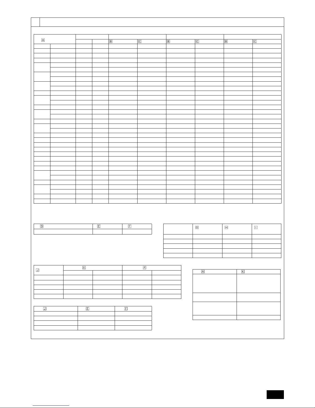
A [Standard]
Outdoor model
Unit combination A A1 *1 A2 *1
Unit 1 Unit 2
High-pressure side Low-pressure side High-pressure side Low-pressure side High-pressure side Low-pressure side
P200 YJM-A - - ø15.88 ø19.05 - - - P250 YJM-A - - ø19.05 ø22.2 - - - P300 YJM-A - - ø19.05 ø22.2 - - - P350 YJM-A - - ø19.05 ø28.58 - - - P400 YJM-A - - ø22.2 ø28.58 - - - -
YSJM-A1 P200 P200 ø22.2 ø28.58 ø15.88 ø19.05 ø15.88 ø19.05
P450 YJM-A - - ø22.2 ø28.58 - - - -
YSJM-A1 P250 P200 ø22.2 ø28.58 ø19.05 ø22.2 ø15.88 ø19.05
P500 YSJM-A P250 P250 ø22.2 ø28.58 ø19.05 ø22.2 ø19.05 ø22.2
YSJM-A1 P300 P200 ø22.2 ø28.58 ø19.05 ø22.2 ø15.88 ø19.05
P550 YSJM-A P300 P250 ø28.58 ø28.58 ø19.05 ø22.2 ø19.05 ø22.2
P600 YSJM-A P300 P300 ø28.58 ø28.58 ø19.05 ø22.2 ø19.05 ø22.2
YSJM-A1 P350 P250 ø28.58 ø28.58 ø19.05 ø28.58 ø19.05 ø22.2
P650 YSJM-A P350 P300 ø28.58 ø28.58 ø19.05 ø28.58 ø19.05 ø22.2
P700 YSJM-A P400 P300 ø28.58 ø34.93 ø22.2 ø28.58 ø19.05 ø22.2
YSJM-A1 P350 P350 ø28.58 ø34.93 ø19.05 ø28.58 ø19.05 ø28.58
P750 YSJM-A P400 P350 ø28.58 ø34.93 ø22.2 ø28.58 ø19.05 ø28.58
P800 YSJM-A P400 P400 ø28.58 ø34.93 ø22.2 ø28.58 ø22.2 ø28.58
YSJM-A1 P450 P350 ø28.58 ø34.93 ø22.2 ø28.58 ø19.05 ø28.58
P850 YSJM-A P450 P400 ø28.58 ø41.28 ø22.2 ø28.58 ø22.2 ø28.58
P900 YSJM-A P450 P450 ø28.58 ø41.28 ø22.2 ø28.58 ø22.2 ø28.58
EP200 YJM-A - - ø15.88 ø19.05 - - - EP250 YJM-A - - ø19.05 ø22.2 - - - EP300 YJM-A - - ø19.05 ø22.2 - - - EP350 YJM-A - - ø19.05 ø28.58 - - - EP400 YSJM-A EP200 EP200 ø22.2 ø28.58 ø15.88 ø19.05 ø15.88 ø19.05
EP450 YSJM-A EP250 EP200 ø22.2 ø28.58 ø19.05 ø22.2 ø15.88 ø19.05
EP500 YSJM-A EP300 EP200 ø22.2 ø28.58 ø19.05 ø22.2 ø15.88 ø19.05
YSJM-A1 EP250 EP250 ø22.2 ø28.58 ø19.05 ø22.2 ø19.05 ø22.2
EP550 YSJM-A EP300 EP250 ø28.58 ø28.58 ø19.05 ø22.2 ø19.05 ø22.2
EP600 YSJM-A EP300 EP300 ø28.58 ø28.58 ø19.05 ø22.2 ø19.05 ø22.2
YSJM-A1 EP350 EP250 ø28.58 ø28.58 ø19.05 ø28.58 ø19.05 ø22.2
EP650 YSJM-A EP350 EP300 ø28.58 ø28.58 ø19.05 ø28.58 ø19.05 ø22.2
EP700 YSJM-A EP350 EP350 ø28.58 ø34.93 ø19.05 ø28.58 ø19.05 ø28.58
*1 The pipe sizes listed in columns A1 to A2 in this table correspond to the sizes for the models listed in the unit 1 and 2 columns. When the order of unit 1 and 2 is
changed, make sure to use the appropriate pipe size for the model.
B (mm) C, D, E (mm)
Total capacity of indoor units
Liquid pipe Gas pipe
Downstream unit
model total
High-pressure
gas pipe
Low-pressure
gas pipe
Liquid pipe
~ 80
ø9.52 ø15.88
~ 200 ø15.88 ø19.05 ø9.52
201 ~ 300 ø19.05 ø22.2 ø9.52
301 ~ 350 ø19.05 ø28.58 ø12.7
351 ~ 400 ø22.2 ø28.58 ø12.7
401 ~ 450 ø22.2 ø28.58 ø15.88
g, h, i, j (mm)
Model number
Liquid pipe Gas pipe
gh i j
100 ø9.52 ø9.52 ø15.88 ø15.88
125 ø9.52 ø9.52 ø15.88 ø15.88
140 ø9.52 ø9.52 ø15.88 ø15.88
200 ø9.52 ø9.52 ø19.05 ø15.88
250 ø9.52 ø9.52 ø22.2 ø15.88
a, b, c, d, e, f (mm)
Model number
Liquid pipe Gas pipe
15, 20, 25, 32, 40, 50 ø6.35 ø12.7
63, 71, 80, 100, 125, 140 ø9.52 ø15.88
200 ø9.52 ø19.05
250 ø9.52 ø22.2
Outdoor model
Outdoor twinning kit
P500 ~ P650YSJM-A
P400 ~ P600YSJM-A1
EP400 ~ EP600YSJM-A
EP500YSJM-A1
CMY-R100VBK
P700 ~ P800YSJM-A
P700YSJM-A1
CMY-R200VBK
P800YSJM-A1
EP650, EP700YSJM-A
EP600YSJM-A1
CMY-R100XLVBK
P850, P900YSJM-A CMY-R200XLVBK
6
9
9.2
[Fig. 9.2.2]
A
C
D
B
C
D
<A> The piping from the outdoor units to twinning pipe must be made to slope downwards the twinning pipe. (high-pressure side only)
<B> Slope of twinning pipe (high pressure side only)
±15°
D
E
<C> Pipe connection example
F
H
G
J
K
I
A:
Downward slope
B:
Upward slope
C:
BC controller (standard or main)
D:
Twinning pipe
E:
Slope of the twinning pipe is at an angle within ±15° to the ground
F:
Twinning pipe (low-pressure side)
G:
Twinning pipe (high-pressure side)
H:
On-site piping (low-pressure connecting pipe: between outdoor units)
I:
On-site piping (low-pressure main pipe: to BC controller)
J:
On-site piping (high-pressure main pipe: to BC controller)
K:
Straight run of pipe that is 500 mm or more
10
10.2
[Fig. 10.2.1]
<A> Refrigerant service valve (High-pressure side/brazed type)
<B> Refrigerant service valve (Low-pressure side/brazed type)
A
E
D
G
F
<A>
<B>
S
O
F
G
E
A
<A>
<B>
D
C
D
B
P200~P400
EP200
~EP300
P450
EP350
A:
Shaft
B:
Shaft
C:
Stopper pin
D:
Service port
E:
Cap
F:
Pinched connecting pipe severing portion
G:
Pinched connecting pipe brazing portion
[Fig. 10.2.3]
A
B
A:
Example of closure materials (fi eld supply)
B:
Fill the gap at the site
* When not attaching a low-pressure twinning pipe.
7
10
10.2
[Fig. 10.2.2]
No.
12345
A Shape
ø22.2
ID ø25.4
ID ø22.2
OD ø19.05
ø22.2
ID ø25.4
ID ø28.58
ø28.58
ID ø25.4
ID ø19.05
OD ø19.05
OD ø28.58
ø28.58
ID ø28.58
P250YJM 1 <C> Low-pressure side - - - P300YJM 1 <C> Low-pressure side - - - P350YJM - 1 <D> High-pressure side 1 <C> Low-pressure side 1 <D> High-pressure side P400YJM 1 <D> High-pressure side - 1 <C> Low-pressure side - -
P450YJM 1 <D> High-pressure side - - - 1 <C> Low-pressure side
EP250YJM 1 <C> Low-pressure side 1 <D> High-pressure side - 1 <D> High-pressure side EP300YJM 1 <C> Low-pressure side 1 <D> High-pressure side - 1 <D> High-pressure side EP350YJM - 1 <D> High-pressure side - 1 <D> High-pressure side 1 <C> Low-pressure side
<A> Front pipe routing
B When not attaching a low-pressure twinning pipe
F
E
<C>
<D>
D
A
B
C When attaching a low-pressure twinning pipe *1,*2
G
H
I
F
<C>
<D>
<B> Bottom pipe routing
B When not attaching a low-pressure twinning pipe
D
E
F
<C>
<D>
C
D
*3
K
L
J
<E> Severing portion
referral fi gure
C When attaching a low-pressure twinning pipe *1,*2
F
H
I
G
<C>
<D>
<A> Front pipe routing <B> Bottom pipe routing <C> Low-pressure side
<D> High-pressure side <E> Severing portion referral fi gure
A:
Shape
B:
When not attaching a low-pressure twinning pipe
C:
When attaching a low-pressure twinning pipe
D:
Refrigerant service valve piping
E:
On-site piping (low-pressure connecting pipe)
F:
On-site piping (high-pressure connecting pipe)
G:
Twinning kit (sold separately)
H:
On-site piping (low-pressure connecting pipe: to BC controller)
I:
On-site piping (low-pressure connecting pipe: to outdoor unit)
J:
75 mm (reference measurement)
K:
ID ø25.4 side
L:
Severing portion
*1 For the attachment of the Twinning pipe (sold separately), refer to the instructions included in the kit.
*2 Connection pipe is not used when the Twinning kit is attached.
*3 Use a pipe cutter to sever.
10.3
[Fig. 10.3.1]
D
C
C
B
B
E
F
G
H
I
J
A
LOW
HI
A:
Nitrogen gas
B:
To indoor unit
C:
System analyzer
D:
Low knob
E:
Hi knob
F:
Val ve
G:
Low-pressure pipe
H:
High-pressure pipe
I:
Outdoor unit
J:
Service port
8
10
10.3
[Fig. 10.3.2]
LOW
HI
B
A
K
J
L
H
M
C
D
EN
N
O
F
G
I
A:
System analyzer
B:
Low knob
C:
Hi knob
D:
Val ve
E:
Low-pressure pipe
F:
High-pressure pipe
G:
Service port
H:
Three-way joint
I:
Val ve
J:
Val ve
K:
R410A cylinder
L:
Scale
M:
Vacuum pump
N:
To indoor unit
O:
Outdoor unit
[Fig. 10.3.3]
A
B:
In case of the R410A cylinder having no syphon pipe.
A:
Syphon pipe
10.4
[Fig. 10.4.1] [Fig. 10.4.2] [Fig. 10.4.3]
C
A
B
D
E
B
A
D
C
E
E
E
D
A
B
A:
Steel wire
A:
High-pressure pipe
B:
Piping
B:
Low-pressure pipe
C:
Asphaltic oily mastic or asphalt
C:
Electric wire
D:
Heat insulation material A
D:
Finishing tape
E:
Outer covering B
E:
Insulator
[Fig. 10.4.4]
<A> Inner wall (concealed) <B> Outer wall <C> Outer wall (exposed) <D> Floor (waterproofi ng)
A B
A B
D
C
E
A
B
D
F
G
B
<E> Roof pipe shaft <F> Penetrating portion on fi re
limit and boundary wall
A:
Sleeve
B:
Heat insulating material
C:
Lagging
D:
Caulking material
E:
Band
F:
Waterproofi ng layer
G:
Sleeve with edge
H:
Lagging material
I:
Mortar or other incombustible caulking
J:
Incombustible heat insulation material
F
H
D
B
G
I
A
J
1m1m
9
11
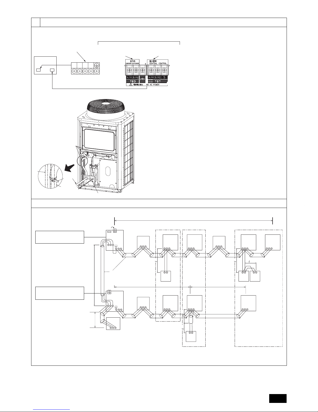
11.2
[Fig. 11.2.1]
A:
Power source
B:
Transmission line
C:
Earth screw
C
L1 L2 L3 N
Terminal block for indoor –
outdoor transmission line
(TB3)
Terminal block for
centralized control
(TB7)
Power supply terminal block
(TB1)
Control box
A
B
[Fig. 11.2.2]
A:
Cable strap
B:
Power source cable
C:
Transmission cable
D:
Pillar
A
B
C
D
A
B
11.3
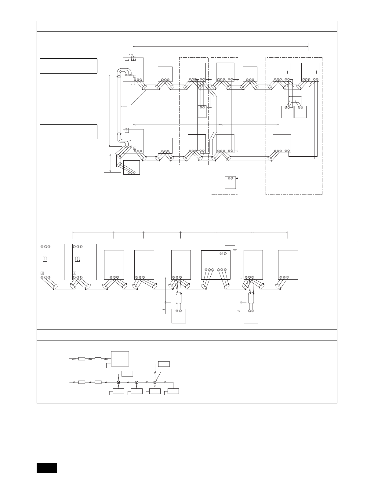
[Fig. 11.3.1]
A B C
E
D
M1M2
M1M2
S
TB7
TB3
IC
(51)
M1 M2 S
TB5
RC
(01)
IC
M1 M2 S
TB5
(02)
IC
M1 M2 S
TB5
(04)
IC
M1 M2 S
TB5
(03)
IC
M1 M2 S
TB5
(05)
IC
M1 M2 S
TB5
(07)
IC
M1 M2 S
TB5
(06)
L2
L1
(101)
RC
(105)
RC
(103)
RC
(155)
M1M2
M1M2
S
TB7
TB3
CN41
(53)
OC
3
ABS
System
controller
L3
L6
L4
L5
2
4
1
AB AB AB
AB
BC
M1 M2 S
(52)
BS
M1 M2 S
(55)
BC
M1 M2 S
(54)
TB02
TB02
TB02
OC
CN41
CN41
CN40
<A> Change the jumper connector
from CN41 to CN40 *1
<B> SW2-1:ON *2
( ) Address
<C> Keep the jumper connector
on CN41
<B> SW2-1:ON *2
*1 When the power supply unit is not connected to the transmission line for centralized control, disconnect the male power supply connector (CN41) from ONE outdoor unit in the system and
connect it to CN40.
*2 If a system controller is used, set SW2-1 on all of the outdoor units to ON.
10
11
11.3
[Fig. 11.3.2]
A B C
E
D
M1M2
M1M2
M1M2
S
TB7
TB3
IC
(51)
M1 M2 12S
TB5 TB15
12
TB15
12
TB15
12
TB15
12
TB15
12
TB15
MA
(01)
IC
M1 M2 S
TB5
(02)
IC
M1 M2 S
TB5
(04)
IC
M1 M2 S
TB5
(03)
IC
M1 M2 S
TB5
(05)
IC
M1 M2 S
TB5
(07)
IC
M1 M2 S
TB5
(06)
L2
L1
MAMAMA
M1M2
S
TB7
TB3
(53)
m1
m4
m3
S
System
controller
L3
L6
L4
m2
ABABAB
AB
AB
m2
m1
m1
m2
BC
M1 M2 S
(52)
BS
M1 M2 S
(55)
BC
M1 M2 S
(54)
TB02
TB02
TB02
CN41
CN40
OC
OC
CN41
<A> Change the jumper connector
from CN41 to CN40 *1
<B> SW2-1:ON *2
<C> Keep the jumper connector
on CN41
<B> SW2-1:ON *2
A:
Group 1
B:
Group 3
C:
Group 5
D:
Shielded wire
E:
Sub remote controller
( ): Address
*1 When the power supply unit is not connected to the transmission line for centralized control, disconnect the male power supply connector (CN41) from ONE outdoor unit in the system and
connect it to CN40.
*2 If a system controller is used, set SW2-1 on all of the outdoor units to ON.
[Fig. 11.3.3]
RC
ICBC
M1M2 S
TB5
IC
M1M2 S
TB5
RP
Ground
AB
ABAB
S
TB2
ABS
TB3
L15 1
1
L18
RC
IC
M1M2 S
TB5
IC
M1M2 S
TB5
L17L16L14L13
M1M2 S
M1M2
TB3
M1M2
TB3
M1M2 S
TB7
M1M2 S
TB7
OC
(51)
L11 L12
OS
(52)
CN41 CN41
TB02
• ( ) Address
• Daisy-chain terminals (TB3) on outdoor units in the same refrigerant
system together.
• Leave the power jumper connector on CN41 as it is. When connecting
a system controller to the transmission line (TB7) for centralized control,
refer to [Fig. 11.3.1], [Fig. 11.3.2], or DATA BOOK.
11.4
[Fig. 11.4.1]
BA
C
3N~380 - 415V
L
1, L2, L3, N
BA
~220 - 240V
L, N
Earth
Earth
EarthEEarth Earth
E
F
F’
D
EE
A:
Switch (Breakers for wiring and current leakage)
B:
Breakers for current leakage
C:
Outdoor unit
D:
Pull box
E:
Indoor unit
F:
BC controller (standard or main)
F':
BC controller (sub)
11
GB
1.1. Before installation and electric work
X Before installing the unit, make sure you read all the
“Safety precautions”.
X The “Safety precautions” provide very important points
regarding safety. Make sure you follow them.
Symbols used in the text
Warning:
Describes precautions that should be observed to prevent danger of injury
or death to the user.
Caution:
Describes precautions that should be observed to prevent damage to the
unit.
Symbols used in the illustrations
: Indicates an action that must be avoided.
: Indicates that important instructions must be followed.
: Indicates a part which must be grounded.
: Beware of electric shock. (This symbol is displayed on the main unit
label.) <Color: yellow>
Warning:
Carefully read the labels affi xed to the main unit.
HIGH VOLTAGE WARNING:
Control box houses high-voltage parts.
When opening or closing the front panel of the control box, do not let it
come into contact with any of the internal components.
Before inspecting the inside of the control box, turn off the power,
keep the unit off for at least 10 minutes, and confi rm that the voltage
between FT-P and FT-N on INV Board has dropped to DC20V or less.
(It takes about 10 minutes to discharge electricity after the power
supply is turned off.)
Warning:
Ask the dealer or an authorized technician to install the air conditioner.
- Improper installation by the user may result in water leakage, electric
shock, or fi re.
This appliance is not intended for use by persons (including children)
with reduced physical, sensory or mental capabilities, or lack of
experience and knowledge, unless they have been given supervision
or instruction concerning use of the appliance by a person responsible
for their safety.
Install the unit at a place that can withstand its weight.
- Failure to do so may cause the unit to fall down, resulting in injuries and
damage to the unit.
Use the specifi ed cables for wiring. Make the connections securely so
that the outside force of the cable is not applied to the terminals.
- Inadequate connection and fastening may generate heat and cause a fi re.
Prepare for strong winds and earthquakes and install the unit at the
specifi ed place.
- Improper installation may cause the unit to topple and result in injury and
damage to the unit.
Always use fi lters and other accessories specifi ed by Mitsubishi Electric.
- Ask an authorized technician to install the accessories. Improper
installation by the user may result in water leakage, electric shock, or fi re.
•
•
•
•
•
•
•
•
•
Never repair the unit. If the air conditioner must be repaired, consult
the dealer.
- If the unit is repaired improperly, water leakage, electric shock, or fi re may
result.
If the supply cord is damaged, it must be replaced by the manufacturer,
its service agent or similarly qualifi ed persons in order to avoid a
hazard.
Do not touch the heat exchanger fi ns.
- Improper handling may result in injury.
If refrigerant gas leaks during installation work, ventilate the room.
- If the refrigerant gas comes into contact with a fl ame, poisonous gases will
be released.
Install the air conditioner according to this Installation Manual.
- If the unit is installed improperly, water leakage, electric shock, or fi re may
result.
Have all electric work done by a licensed electrician according
to “Electric Facility Engineering Standard” and “Interior Wire
Regulations” and the instructions given in this manual and always use
a dedicated power supply.
- If the power source capacity is inadequate or electric work is performed
improperly, electric shock and fi re may result.
Securely install the outdoor unit terminal cover (panel).
- If the terminal cover (panel) is not installed properly, dust or water may
enter the outdoor unit and fi re or electric shock may result.
When installing and moving the air conditioner to another site, do not
charge it with a refrigerant different from the refrigerant specifi ed on
the unit.
- If a different refrigerant or air is mixed with the original refrigerant, the
refrigerant cycle may malfunction and the unit may be damaged.
If the air conditioner is installed in a small room, measures must be
taken to prevent the refrigerant concentration from exceeding the
safety limit if the refrigerant should leak.
- Consult the dealer regarding the appropriate measures to prevent the
safety limit from being exceeded. Should the refrigerant leak and cause
the safety limit to be exceeded, hazards due to lack of oxygen in the room
could result.
When moving and reinstalling the air conditioner, consult the dealer or
an authorized technician.
- If the air conditioner is installed improperly, water leakage, electric shock,
or fi re may result.
After completing installation work, make sure that refrigerant gas is not
leaking.
- If the refrigerant gas leaks and is exposed to a fan heater, stove, oven, or
other heat source, it may generate noxious gases.
Do not reconstruct or change the settings of the protection devices.
- If the pressure switch, thermal switch, or other protection device is shorted
or operated forcibly, or parts other than those specifi ed by Mitsubishi
Electric are used, fi re or explosion may result.
To dispose of this product, consult your dealer.
The installer and system specialist shall secure safety against leakage
according to local regulation or standards.
- Choose the appropriate wire size and the switch capacities for the main
power supply described in this manual if local regulations are not available.
Pay special attention to the place of installation, such as a basement,
etc. where refrigeration gas can accumulate, since refrigerant is
heavier than the air.
For outdoor units that allow fresh air intake to the indoor unit, the
installation site must be carefully chosen to ensure only clean air can
enter the room.
- Direct exposure to outdoor air may have harmful effects on people or food.
Children should be supervised to ensure that they do not play with the
appliance.
•
•
•
•
•
•
•
•
•
•
•
•
•
•
•
•
•
1. Safety precautions
Contents
1. Safety precautions ......................................................................................11
1.1. Before installation and electric work ...........................................11
1.2. Precautions for devices that use R410A refrigerant .................. 12
1.3. Before installation ...................................................................... 12
1.4. Before installation (relocation) - electrical work ......................... 12
1.5. Before starting the test run ........................................................ 12
2. About the product ....................................................................................... 13
3. Combination of outdoor units ..................................................................... 13
4. Specifi cations ............................................................................................. 13
5. Confi rmation of parts attached ................................................................... 14
6. Space required around unit ........................................................................ 14
7. Lifting method ............................................................................................ 15
8. Installation of unit ....................................................................................... 15
8.1. Installation ................................................................................. 15
9. Refrigerant piping installation ..................................................................... 15
9.1. Caution ...................................................................................... 15
9.2. Refrigerant piping system ........................................................ 16
10. Additional refrigerant charge ...................................................................... 17
10.1. Calculation of additional refrigerant charge ............................... 17
10.2. Precautions concerning piping connection and valve operation 18
10.3. Airtight test, evacuation, and refrigerant charging ..................... 19
10.4. Thermal insulation of refrigerant piping ..................................... 20
11. Wiring (For details, refer to the installation manual of each unit and
controller.) .................................................................................................. 20
11.1. Caution ...................................................................................... 20
11.2. Control box and connecting position of wiring ........................... 20
11.3. Wiring transmission cables ....................................................... 21
11.4. Wiring of main power supply and equipment capacity .............. 22
12. Test run ...................................................................................................... 23
12.1. The following phenomena do not represent faults. ................... 23
13. Information on rating plate ......................................................................... 24

12
GB
1.4. Before installation (relocation) -
electrical work
Caution:
Ground the unit.
- Do not connect the ground wire to gas or water pipes, lightning rods, or
telephone ground lines. Improper grounding may result in electric shock.
Never connect in reverse phases.
Never connect the Power Line L1, L2, and L3 to Terminal N.
- If the unit is miss wired, when power is supplied, some electrical parts will
be damaged.
Install the power cable so that tension is not applied to the cable.
- Tension may cause the cable to break and generate heat and cause a fi re.
Install a leak circuit breaker, as required.
- If a leak circuit breaker is not installed, electric shock may result.
Use power line cables of suffi cient current carrying capacity and rating.
- Cables that are too small may leak, generate heat, and cause a fi re.
Use only a circuit breaker and fuse of the specifi ed capacity.
- A fuse or circuit breaker of a larger capacity, or the use of a substitute
simple steel or copper wire may result in a general unit failure or fi re.
Do not wash the air conditioner units.
- Washing them may cause an electric shock.
Be careful that the installation base is not damaged by long use.
- If the damage is left uncorrected, the unit may fall and cause personal
injury or property damage.
Install the drain piping according to this Installation Manual to ensure
proper drainage. Wrap thermal insulation around the pipes to prevent
condensation.
- Improper drain piping may cause water leakage and damage to furniture
and other possessions.
Be very careful about transporting the product.
- One person should not carry the product. Its weight is in excess of 20kg.
- Some products use PP bands for packaging. Do not use any PP bands as
a means of transportation. It is dangerous.
- Do not touch the heat exchanger fi ns. Doing so may cut your fi ngers.
- When transporting the outdoor unit, support it at the specifi ed positions on
the unit base. Also support the outdoor unit at four points so that it cannot
slip sideways.
Safely dispose of the packing materials.
- Packing materials, such as nails and other metal or wooden parts, may
cause stabs or other injuries.
- Tear apart and throw away plastic packaging bags so that children will not
play with them. If children play with a plastic bag which has not been torn
apart, they face the risk of suffocation.
1.5. Before starting the test run
Caution:
Turn on the power at least 12 hours before starting operation.
- Starting operation immediately after turning on the main power switch
can result in irreversible damage to internal parts. Keep the power switch
turned on during the operational season. Make sure of the phase order of
power supply and voltage between each phase.
Do not touch the switches with wet fi ngers.
- Touching a switch with wet fi ngers can result in an electric shock.
Do not touch the refrigerant pipes during and immediately after
operation.
- During and immediately after operation, the refrigerant pipes may be hot
or cold, depending on the condition of the refrigerant fl owing through the
refrigerant piping, compressor, and other refrigerant cycle parts. Your
hands may suffer burns or frostbite if you touch the refrigerant pipes.
Do not operate the air conditioner with the panels and guards removed.
- Rotating, hot, or high-voltage parts can cause injuries.
Do not turn off the power immediately after stopping operation.
- Always wait at least 5 minutes before turning off the power. Otherwise,
drainage water leakage or mechanical failure of sensitive parts may occur.
Do not touch the surface of the compressor during servicing.
- If unit is connected to a supply and not running, the crank case heater
located at the base of the compressor may still be operating.
•
•
•
•
•
•
•
•
•
•
•
•
•
•
•
•
•
1.2. Precautions for devices that use
R410A refrigerant
Caution:
Do not use existing refrigerant piping.
- The old refrigerant and refrigerant oil in the existing piping contains a large
amount of chlorine which may cause the refrigerant oil of the new unit to
deteriorate.
- R410A is a high-pressure refrigerant and can cause the existing piping to
burst.
Use refrigerant piping made of phosphorus deoxidized copper and
copper alloy seamless pipes and tubes. In addition, be sure that the
inner and outer surfaces of the pipes are clean and free of hazardous
sulphur, oxides, dust/dirt, shaving particles, oils, moisture, or any other
contaminant.
- Contaminants on the inside of the refrigerant piping may cause the
refrigerant oil to deteriorate.
Store the piping to be used during installation indoors and keep both
ends of the piping sealed until just before brazing. (Store elbows and
other joints in a plastic bag.)
- If dust, dirt, or water enters the refrigerant cycle, deterioration of the oil and
compressor failure may result.
Apply a small amount of ester oil, ether oil, or alkyl benzene to fl ares.
(for indoor unit)
- Infi ltration of a large amount of mineral oil may cause the refrigerant oil to
deteriorate.
Use liquid refrigerant to fi ll the system.
- If gas refrigerant is used to fi ll the system, the composition of the
refrigerant in the cylinder will change and performance may drop.
Do not use a refrigerant other than R410A.
- If another refrigerant (R22, etc.) is mixed with R410A, the chlorine in the
refrigerant may cause the refrigerant oil to deteriorate.
Use a vacuum pump with a reverse fl ow check valve.
- The vacuum pump oil may fl ow back into the refrigerant cycle and cause
the refrigerant oil to deteriorate.
Do not use the following tools that are used with conventional
refrigerants.
(Gauge manifold, charge hose, gas leak detector, reverse fl ow check
valve, refrigerant charge base, refrigerant recovery equipment)
- If the conventional refrigerant and refrigerant oil are mixed in the R410A,
the refrigerant may deteriorate.
- If water is mixed in the R410A, the refrigerant oil may deteriorate.
- Since R410A does not contain any chlorine, gas leak detectors for
conventional refrigerants will not react to it.
Do not use a charging cylinder.
- Using a charging cylinder may cause the refrigerant to deteriorate.
Be especially careful when managing the tools.
- If dust, dirt, or water gets into the refrigerant cycle, the refrigerant may
deteriorate.
1.3. Before installation
Caution:
Do not install the unit where combustible gas may leak.
- If the gas leaks and accumulates around the unit, an explosion may result.
Do not use the air conditioner where food, pets, plants, precision
instruments, or artwork are kept.
- The quality of the food, etc. may deteriorate.
Do not use the air conditioner in special environments.
- Oil, steam, sulfuric smoke, etc. can signifi cantly reduce the performance of
the air conditioner or damage its parts.
When installing the unit in a hospital, communication station, or similar
place, provide suffi cient protection against noise.
- Inverter equipment, private power generator, high-frequency medical
equipment, or radio communication equipment may cause the air
conditioner to operate erroneously, or fail to operate. On the other hand,
the air conditioner may affect such equipment by creating noise that
disturbs medical treatment or image broadcasting.
Do not install the unit on or over things that are subject to water
damage.
- When the room humidity exceeds 80% or when the drain pipe is clogged,
condensation may drip from the indoor unit. Perform collective drainage
work together with the outdoor unit, as required.
•
•
•
•
•
•
•
•
•
•
•
•
•
•
•
13
GB
3. Combination of outdoor units
Component units of PURY-P400 to P900YSJM are listed below.
Outdoor unit model Component unit model
PURY-P200YJM-A(-BS) - PURY-P250YJM-A(-BS) - PURY-P300YJM-A(-BS) - PURY-P350YJM-A(-BS) - PURY-P400YJM-A(-BS) - PURY-P400YSJM-A1(-BS) PURY-P200YJM-A(-BS) PURY-P200YJM-A(-BS)
PURY-P450YJM-A(-BS) - PURY-P450YSJM-A1(-BS) PURY-P250YJM-A(-BS) PURY-P200YJM-A(-BS)
PURY-P500YSJM-A(-BS) PURY-P250YJM-A(-BS) PURY-P250YJM-A(-BS)
PURY-P500YSJM-A1(-BS) PURY-P300YJM-A(-BS) PURY-P200YJM-A(-BS)
PURY-P550YSJM-A(-BS) PURY-P300YJM-A(-BS) PURY-P250YJM-A(-BS)
PURY-P600YSJM-A(-BS) PURY-P300YJM-A(-BS) PURY-P300YJM-A(-BS)
PURY-P600YSJM-A1(-BS) PURY-P350YJM-A(-BS) PURY-P250YJM-A(-BS)
PURY-P650YSJM-A(-BS) PURY-P350YJM-A(-BS) PURY-P300YJM-A(-BS)
PURY-P700YSJM-A(-BS) PURY-P400YJM-A(-BS) PURY-P300YJM-A(-BS)
PURY-P700YSJM-A1(-BS) PURY-P350YJM-A(-BS) PURY-P350YJM-A(-BS)
PURY-P750YSJM-A(-BS) PURY-P400YJM-A(-BS) PURY-P350YJM-A(-BS)
PURY-P800YSJM-A(-BS) PURY-P400YJM-A(-BS) PURY-P400YJM-A(-BS)
PURY-P800YSJM-A1(-BS) PURY-P450YJM-A(-BS) PURY-P350YJM-A(-BS)
PURY-P850YSJM-A(-BS) PURY-P450YJM-A(-BS) PURY-P400YJM-A(-BS)
PURY-P900YSJM-A(-BS) PURY-P450YJM-A(-BS) PURY-P450YJM-A(-BS)
Component units of PURY-EP400 to EP700YSJM are listed below.
Outdoor unit model Component unit model
PURY-EP200YJM-A(-BS) - PURY-EP250YJM-A(-BS) - PURY-EP300YJM-A(-BS) - PURY-EP350YJM-A(-BS) - PURY-EP400YSJM-A(-BS) PURY-EP200YJM-A(-BS) PURY-EP200YJM-A(-BS)
PURY-EP450YSJM-A(-BS) PURY-EP250YJM-A(-BS) PURY-EP200YJM-A(-BS)
PURY-EP500YSJM-A(-BS) PURY-EP300YJM-A(-BS) PURY-EP200YJM-A(-BS)
PURY-EP500YSJM-A1(-BS) PURY-EP250YJM-A(-BS) PURY-EP250YJM-A(-BS)
PURY-EP550YSJM-A(-BS) PURY-EP300YJM-A(-BS) PURY-EP250YJM-A(-BS)
PURY-EP600YSJM-A(-BS) PURY-EP300YJM-A(-BS) PURY-EP300YJM-A(-BS)
PURY-EP600YSJM-A1(-BS) PURY-EP350YJM-A(-BS) PURY-EP250YJM-A(-BS)
PURY-EP650YSJM-A(-BS) PURY-EP350YJM-A(-BS) PURY-EP300YJM-A(-BS)
PURY-EP700YSJM-A(-BS) PURY-EP350YJM-A(-BS) PURY-EP350YJM-A(-BS)
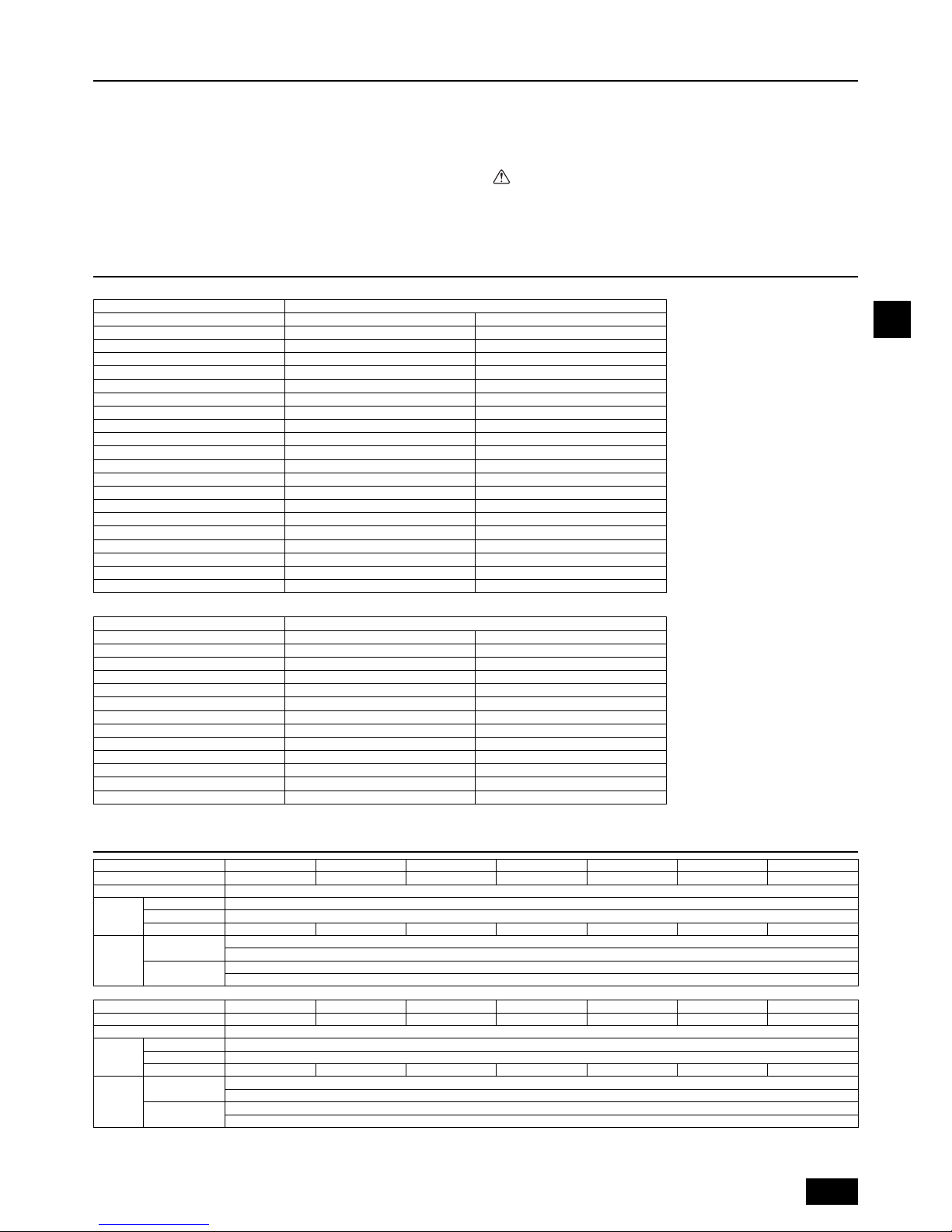
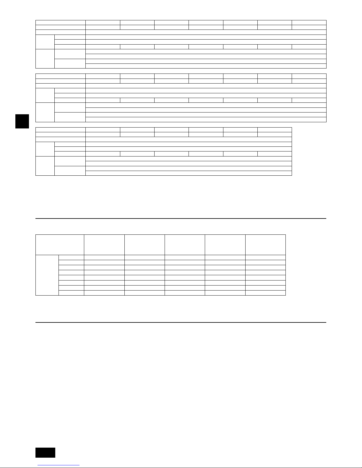
4. Specifi cations
Model
PURY-P200YJM-A PURY-P250YJM-A PURY-P300YJM-A PURY-P350YJM-A PURY-P400YJM-A
PURY-P400YSJM-A1
PURY-P450YJM-A
Noise level (50/60Hz)
56dB <A> 57dB <A> 59dB <A> 60dB <A> 61dB <A> 59dB <A> 62dB <A>
External static pressure
0 Pa *2
Indoor units
Total capacity
50~150% *1
Model
15~250
Quantity
1~20 1~25 1~30 1~35 1~40 1~40 1~45
Operation
temperature
Standard type
Cooling mode: – 5°CDB ~ 46°CDB
Heating mode: – 20°CWB ~ 15.5°CWB
Fresh air intake type
Cooling mode: 21°CDB ~ 43°CDB
Heating mode: – 12.5°CWB ~ 20°CWB
Model
PURY-P450YSJM-A1
PURY-P500YSJM-A
PURY-P500YSJM-A1
PURY-P550YSJM-A PURY-P600YSJM-A
PURY-P600YSJM-A1
PURY-P650YSJM-A
Noise level (50/60Hz)
59.5dB <A> 60dB <A> 61dB <A> 61dB <A> 62dB <A> 62dB <A> 62.5dB <A>
External static pressure
0 Pa *2
Indoor units
Total capacity
50~150% *1
Model
15~250
Quantity
1~45* 1~50* 1~50* 2~50* 2~50* 2~50* 2~50*
Operation
temperature
Standard type
Cooling mode: – 5°CDB ~ 46°CDB
Heating mode: – 20°CWB ~ 15.5°CWB
Fresh air intake type
Cooling mode: 21°CDB ~ 43°CDB
Heating mode: – 12.5°CWB ~ 20°CWB
2. About the product
This unit uses R410A-type refrigerant.
Piping for systems using R410A may be different from that for systems using
conventional refrigerant because the design pressure in systems using
R410A is higher. Refer to the Data Book for more information.
Some of the tools and equipment used for installation with systems that use
other types of refrigerant cannot be used with the systems using R410A.
Refer to the Data Book for more information.
•
•
•
Do not use the existing piping, as it contains chlorine, which is found in
conventional refrigerating machine oil and refrigerant. This chlorine will
deteriorate the refrigerant machine oil in the new equipment. The existing
piping must not be used as the design pressure in systems using R410A
is higher than that in the systems using other types of refrigerant and the
existing pipes may burst.
Caution:
Do not vent R410A into the atmosphere.
R410A is a Fluorinated Greenhouse gas, covered by the Kyoto Protocol
with a Global Warming Potential (GWP) = 1975.
•
•
•
14
GB
Model
PURY-P700YSJM-A
PURY-P700YSJM-A1
PURY-P750YSJM-A PURY-P800YSJM-A
PURY-P800YSJM-A1
PURY-P850YSJM-A
PURY-P900YSJM-A
Noise level (50/60Hz)
63dB <A> 63dB <A> 63.5dB <A> 64dB <A> 64dB <A> 64.5dB <A> 65dB <A>
External static pressure
0 Pa *2
Indoor units
Total capacity
50~150% *1
Model
15~250
Quantity
2~50* 2~50* 2~50* 2~50* 2~50* 2~50* 2~50*
Operation
temperature
Standard type
Cooling mode: – 5°CDB ~ 46°CDB
Heating mode: – 20°CWB ~ 15.5°CWB
Fresh air intake type
Cooling mode: 21°CDB ~ 43°CDB
Heating mode: – 12.5°CWB ~ 20°CWB
Model
PURY-EP200YJM-A PURY-EP250YJM-A PURY-EP300YJM-A PURY-EP350YJM-A
PURY-EP400YSJM-A PURY-EP450YSJM-A PURY-EP500YSJM-A
Noise level (50/60Hz)
57dB <A> 60dB <A> 60dB <A> 61dB <A> 60dB <A> 62dB <A> 62dB <A>
External static pressure
0 Pa *2
Indoor units
Total capacity
50~150% *1
Model
15~250
Quantity
1~20 1~25 1~30 1~35 1~40 1~45 1~50*
Operation
temperature
Standard type
Cooling mode: – 5°CDB ~ 46°CDB
Heating mode: – 20°CWB ~ 15.5°CWB
Fresh air intake type
Cooling mode: 21°CDB ~ 43°CDB
Heating mode: – 12.5°CWB ~ 20°CWB
Model
PURY-EP500YSJM-A1
PURY-EP550YSJM-A
PURY-EP600YSJM-A
PURY-EP600YSJM-A1
PURY-EP650YSJM-A PURY-EP700YSJM-A
Noise level (50/60Hz)
63dB <A> 63dB <A> 63dB <A> 63.5dB <A> 63.5dB <A> 64dB <A>
External static pressure
0 Pa *2
Indoor units
Total capacity
50~150% *1
Model
15~250
Quantity
1~50* 2~50* 2~50* 2~50* 2~50* 2~50*
Operation
temperature
Standard type
Cooling mode: – 5°CDB ~ 46°CDB
Heating mode: – 20°CWB ~ 15.5°CWB
Fresh air intake type
Cooling mode: 21°CDB ~ 43°CDB
Heating mode: – 12.5°CWB ~ 20°CWB
* Connectable branch pipe number is max.48.
*1: The total indoor capacity of units run simultaneously is 150% or less.
*2: To enable high static pressure with (E)P200, (E)P250, (E)P300, (E)P350, P400, and P450, set the DipSW on the main panel as follows.
SW3-9: ON, SW3-10 60Pa compatible: OFF, 30Pa compatible: ON
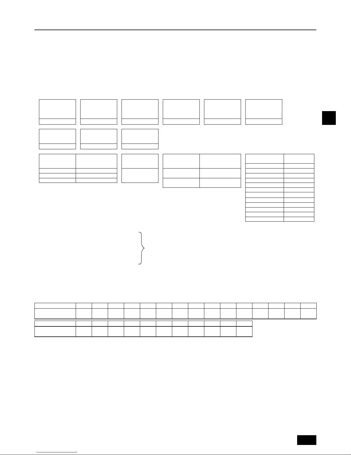
5. Confi rmation of parts attached
This unit includes the following parts. Please check.
For usage methods, refer to item 10.2.
1 Connecting pipe
ID ø25.4, ID ø22.2
<Low-pressure side>
<High-pressure side>
2 Connecting pipe
ID ø25.4, OD ø19.05
<High-pressure side>
3 Connecting pipe
ID ø25.4, ID ø28.58
<Low-pressure side>
4 Connecting elbow
ID ø19.05, OD ø19.05
<High-pressure side>
5 Connecting elbow
ID ø28.58, OD ø28.58
<Low-pressure side>
Model P250YJM 1 pc. – – – –
P300YJM 1 pc. – – – –
P350YJM – 1 pc. 1 pc. 1 pc. –
P400YJM 1 pc. – 1 pc. – –
P450YJM 1 pc. – – – 1 pc.
EP250YJM 1 pc. 1 pc. – 1 pc. –
EP300YJM 1 pc. 1 pc. – 1 pc. –
EP350YJM – 1 pc. – 1 pc. 1 pc.
•
•
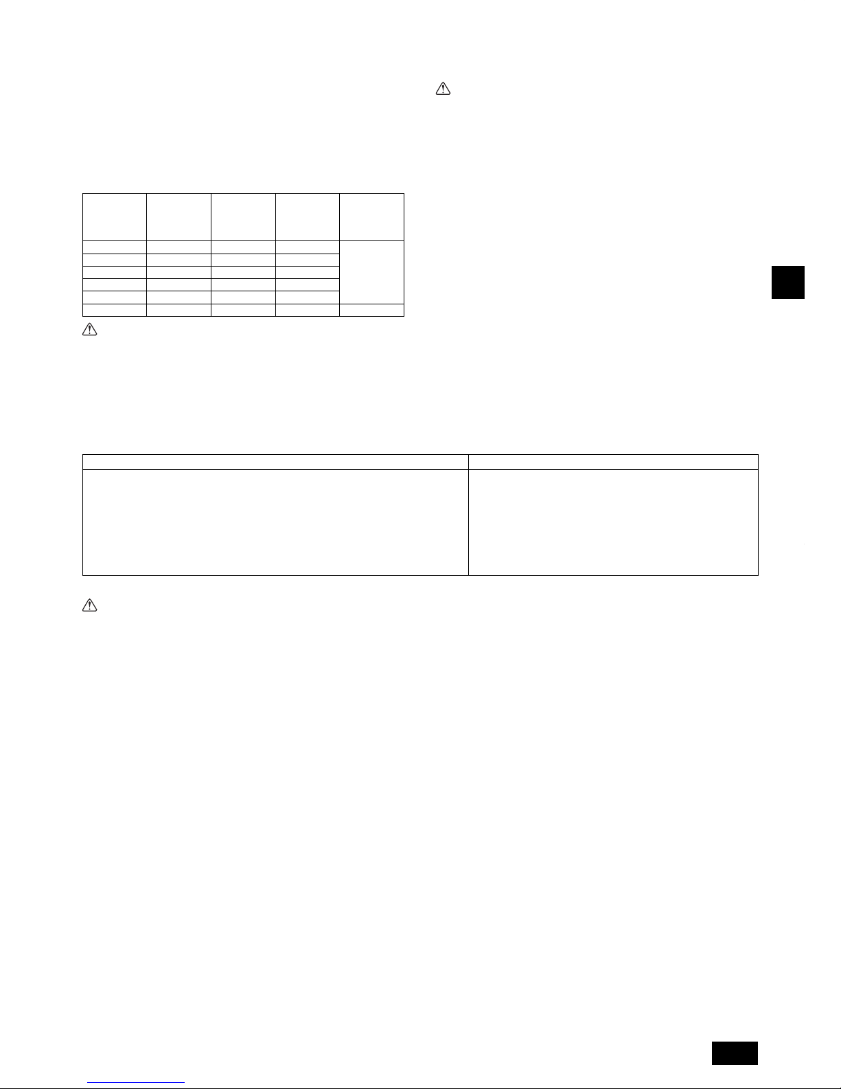
6. Space required around unit
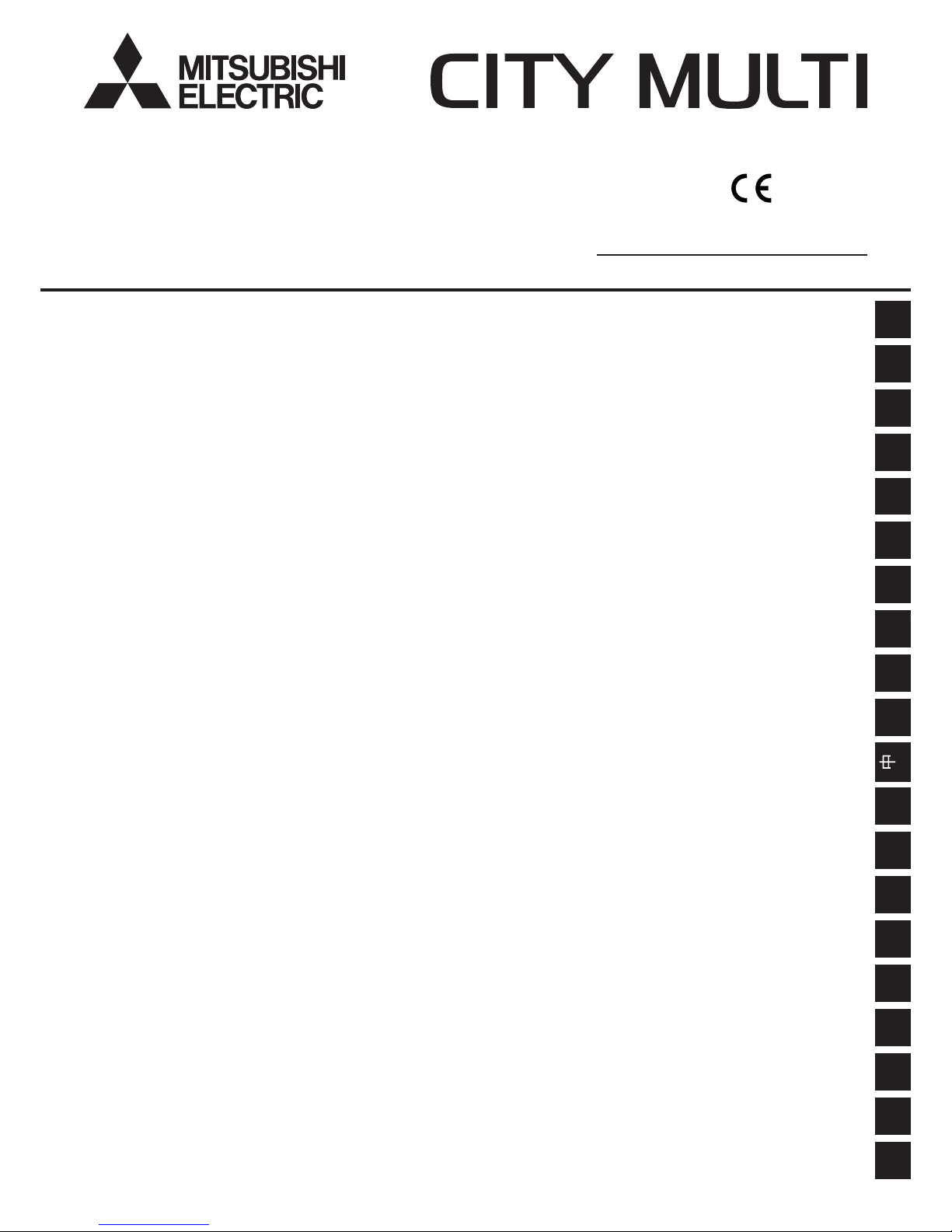
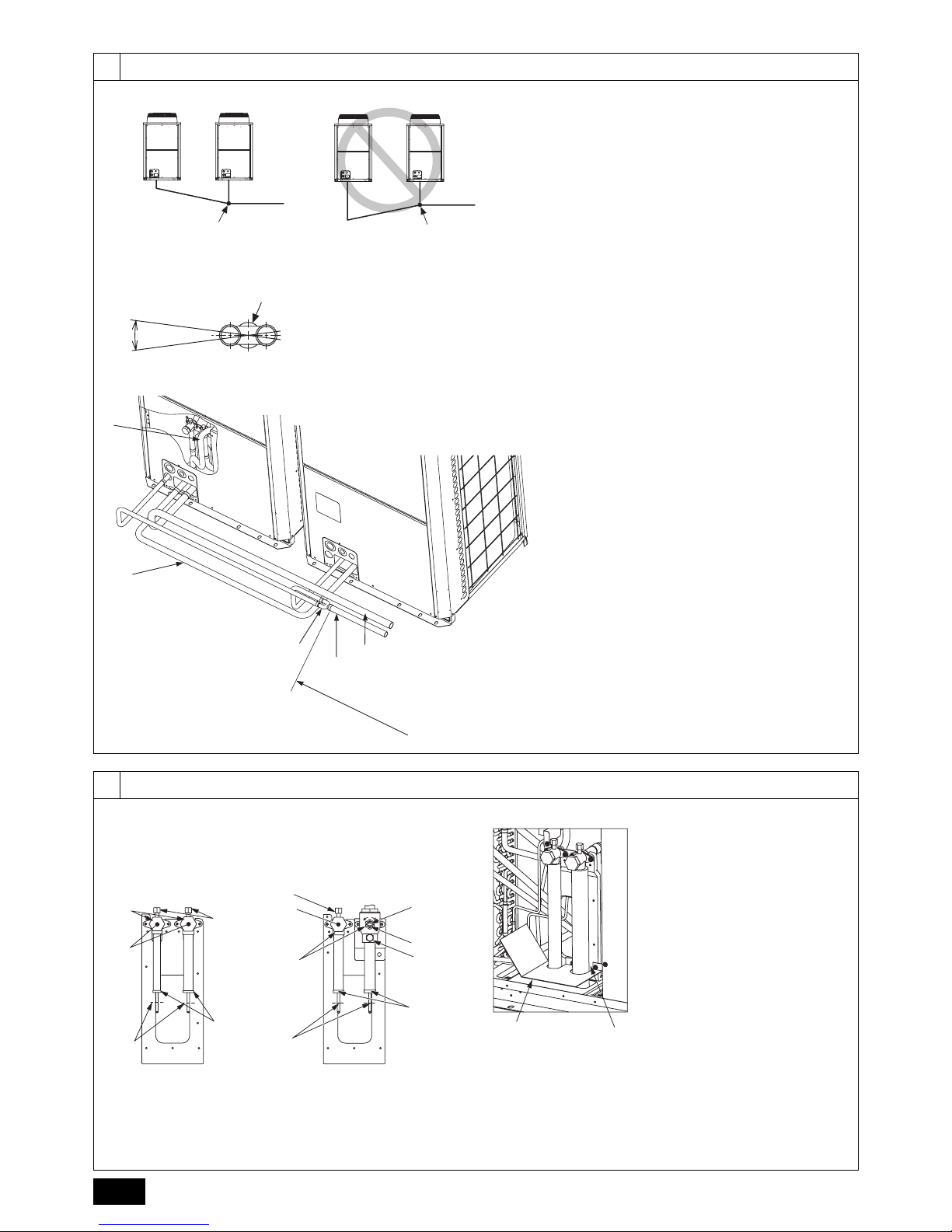
1 In case of single installation
Secure enough space around the unit as shown in the fi gure on page 2.
[Fig. 6.0.1] (P.2)
<A> Top view <B> Side view
<C> When there is little space up to an obstruction
A
Front
B
Unit height
C
Back
D
Air outlet guide (Procured at the site)
(1) If the distance is 300 mm or more between the rear side and the wall
(2) If the distance is 100 mm or more between the rear side and the wall
(3) If the wall height (H) of the front, rear or side exceeds the wall height
restriction
When the height of the walls on the front, back or on the sides <H> exceeds
the wall height limit as defi ned here, add the height that exceeds the height
limit <h> to the fi gures that are marked with an asterisk.
If the unit cannot be kept clear of the wall, please change the direction of the
air outlet of the unit to blow against the wall to avoid air short cycle.
<Wall height limit> Front: Up to the unit height
Back: Up to 500 mm from the unit bottom
Side: Up to the unit height
•
•
•
(4) If there are obstacles at the upper part of the unit
2 In case of collective installation
[Fig. 6.0.2] (P.2)
A
Front
B
Must be open
C
Wall height (H)
When multiple units are installed adjacent to each other, secure enough
space to allow for air circulation and walkway between groups of units as
shown in the fi gures on page 2.
At least two sides must be left open.
As with the single installation, add the height that exceeds the height limit
<h> to the fi gures that are marked with an asterisk.
If there is a wall at both the front and the rear of the unit. Install up to six
units (three units: P450, EP350) consecutively in the side direction and
provide a space of 1000 mm or more as inlet space/passage space for each
six units (three units: P450, EP350).
•
•
•
•
15
GB
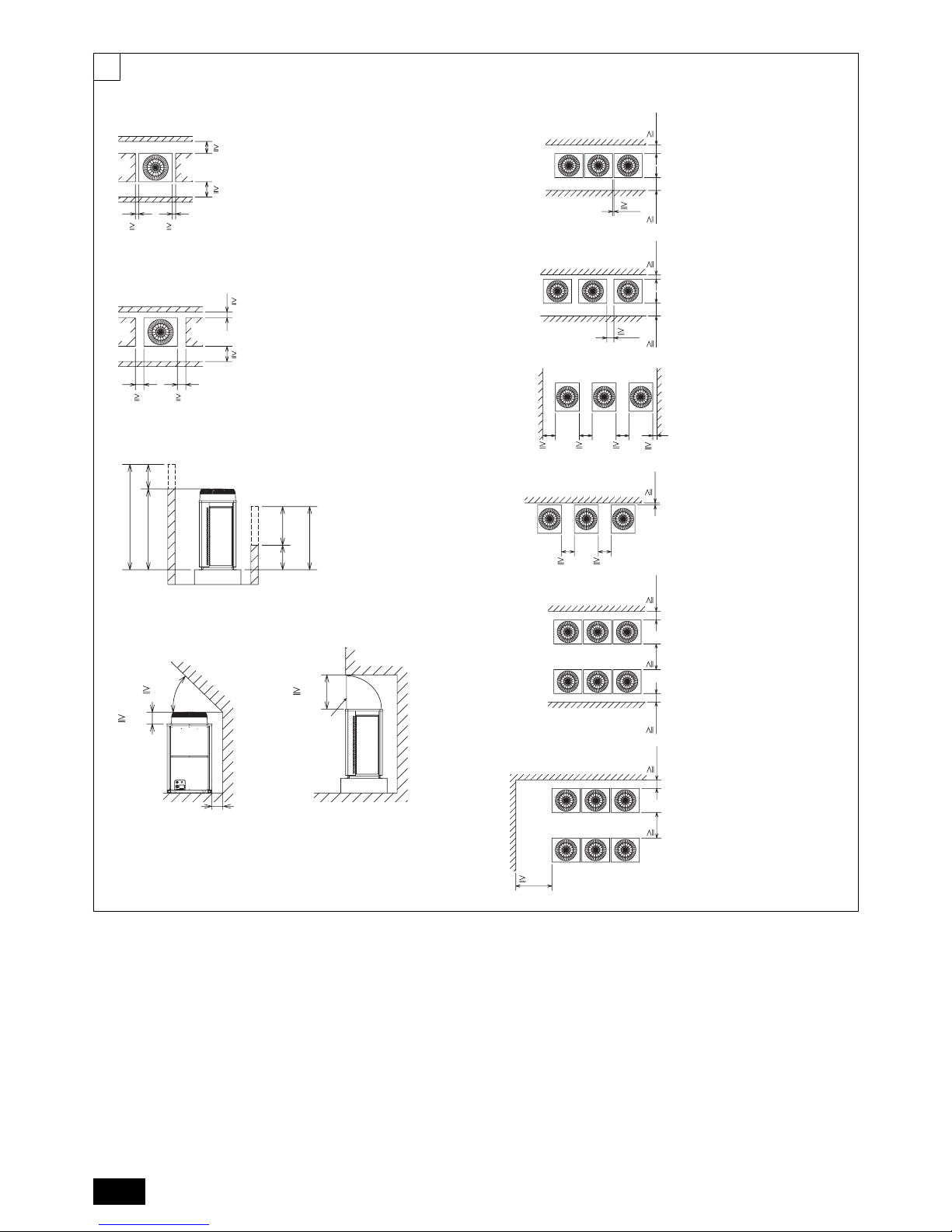
[Fig. 7.0.1] (P.3)
Use suspension ropes that will withstand the weight of the unit.
When moving the unit, use a 4-point suspension, and avoid giving impacts
to the unit (Do not use 2-point suspension).
Place protective pads on the unit where it comes in contact with the ropes to
protect the unit from being scratched.
Set the angle of roping at 40° or less.
Use 2 ropes that are each longer than 8 meters.
•
•
•
•
•
Place protective padding at the corners of the product to protect the product
from scratches or dents that might be caused by the rope.
Caution:
Be very careful when carrying/moving the product.
- When installing the outdoor unit, suspend the unit at the specifi ed location of
the unit base. Stabilize as necessary so that it does not move to the side and
support it at 4 points. If the unit is installed or suspended with 3-point support,
the unit may become unstable and fall.
•
7. Lifting method
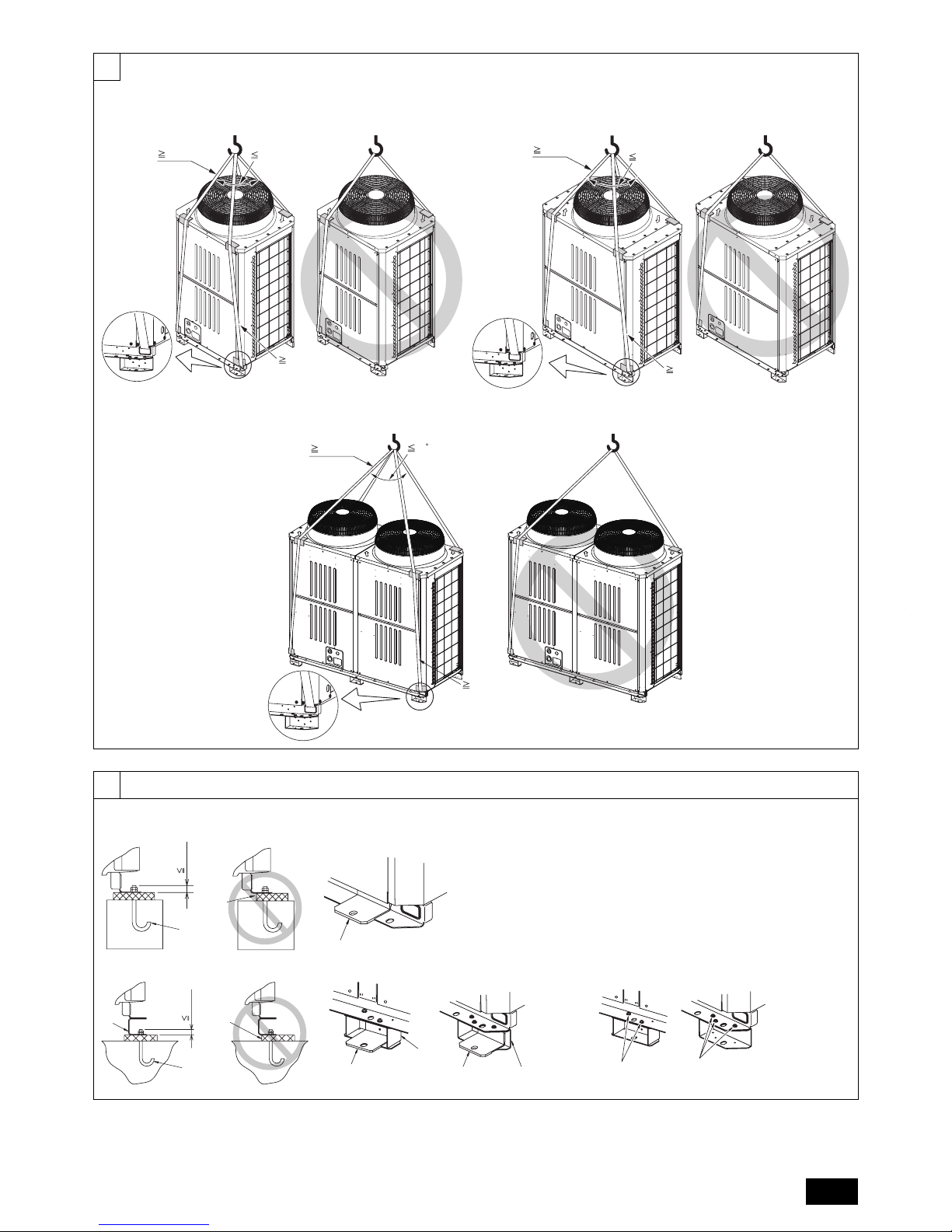
8.1. Installation
[Fig. 8.1.1] (P.3)
<A> Without detachable leg <B> With detachable leg
A
M10 anchor bolt procured at the site.BCorner is not seated.
C
Fixing bracket for the hole-in anchor
bolt (3 locations to fi x with screws).
D
Detachable leg
Fix unit tightly with bolts so that unit will not fall down due to earthquakes or
strong winds.
Use concrete or an angle bracket for the foundation of unit.
Vibration may be transmitted to the installation section and noise and
vibration may be generated from the fl oor and walls, depending on the
installation conditions. Therefore, provide ample vibrationproofi ng (cushion
pads, cushion frame, etc.).
Be sure that the corners are fi rmly seated. If the corners are not fi rmly
seated, the installation feet may be bent.
When using cushion pads, be sure that the full width of the unit is covered.
The projecting length of the anchor bolt should be less than 30 mm.
Hole-in anchor bolts are not compatible with this product. However, if fi xing
brackets are mounted on the 4 locations (6 locations: P450, EP350) of the
unit attachment part, hole-in anchor bolts can be used.
[Fig. 8.1.2]
A
Screws
•
•
•
•
•
•
•
The detachable leg can be removed at the site.
Detaching the detachable leg
Loosen the three screws to detach the detachable leg (Two (three: P450,
EP350) each in the front and back).
If the base leg fi nish is damaged when detaching, be sure to repair at the
site.
Warning:
Be sure to install unit in a place strong enough to withstand its weight.
Any lack of strength may cause unit to fall down, resulting in a
personal injury.
Have installation work in order to protect against strong winds and
earthquakes.
Any installation defi ciency may cause unit to fall down, resulting in a
personal injury.
When building the foundation, give full attention to the fl oor strength, drain water
disposal <during operation, drain water fl ows out of the unit>, and piping and
wiring routes.
Precautions when routing the pipes and wires below the unit (Without
detachable leg)
When routing the pipes and wires below the unit, be sure that the foundation and
base work do not block the base through-holes. Also make sure the foundation
is at least 100 mm high so that the piping can pass under the unit.
•
•
•
•
8. Installation of unit
9. Refrigerant piping installation
The pipe is connected via a terminal-branch type connection in which refrigerant
piping from the outdoor unit is branched at the terminal and is connected to each
of the indoor units.
The method of pipe connection is as follows: fl are connection for the indoor
units, low-pressure pipes and high-pressure pipes for outdoor units, brazed
connection. Note that the branched sections are brazed.
Warning:
Always use extreme care to prevent the refrigerant gas from leaking while
using fi re or fl ame. If the refrigerant gas comes in to contact with a fl ame
from any source, such as a gas stove, it breaks down and generates
a poisonous gas which can cause gas poisoning. Never weld in an
unventilated room. Always conduct an inspection for gas leakage after
installation of the refrigerant piping has been completed.
Caution:
Do not vent R410A into the atmosphere.
R410A is a Fluorinated Greenhouse gas, covered by the Kyoto Protocol
with a Global Warming Potential (GWP) = 1975.
9.1. Caution
This unit uses refrigerant R410A. Follow the local regulations on materials and
pipe thickness when selecting pipes. (Refer to the table below.)
1 Use the following materials for refrigeration piping.
Material: Use copper alloy seamless pipes made of phosphorus
deoxidized copper. Ensure the inner and outer surfaces of the pipes
are clean and free from hazardous sulfur, oxide, dusts, shaving
particles, oils, and moisture (contamination).
Size: Refer to item 9.2. for detailed information on refrigerant piping
system.
2 Commercially available piping often contains dust and other materials.
Always blow it clean with a dry inert gas.
3 Use care to prevent dust, water or other contaminants from entering the
piping during installation.
•
•
•
•
4 Reduce the number of bending portions as much as possible, and make
bending radii as big as possible.
5 For indoor and outdoor branching and merging section, be sure to use the
following twinning pipe sets and merge pipe sets (sold separately).
Indoor twinning pipe kit
model
Indoor junction pipe kit
model
Line branch
Total indoor model
P100 ~ P250
Lower stream unit model
Less than 80 in total
CMY-Y102S-G2 CMY-R160-J1
Outdoor twinning kit model
Total outdoor model
P500 ~ P650YSJM-A
P400 ~ P600YSJM-A1
EP400 ~ EP600YSJM-A
EP500YSJM-A1
Total outdoor model
P700 ~ P800YSJM-A
P700YSJM-A1
Total outdoor model
P800YSJM-A1
EP650, EP700YSJM-A
EP600YSJM-A1
Total outdoor model
P850, P900YSJM-A
CMY-R100VBK CMY-R200VBK
CMY-R100XLVBK CMY-R200XLVBK
Copper pipe size and radial thickness for R410A CITY MULTI.
Size (mm) Size (inch) Radial thickness (mm) Pipe type
ø6.35 ø1/4" 0.8 Type-O
ø9.52 ø3/8" 0.8 Type-O
ø12.7 ø1/2" 0.8 Type-O
ø15.88 ø5/8" 1.0 Type-O
*ø19.05 ø3/4" 1.2 Type-O
*ø19.05 ø3/4" 1.0 Type-1/2H or H
ø22.2 ø7/8" 1.0 Type-1/2H or H
ø25.4 ø1" 1.0 Type-1/2H or H
ø28.58 ø1-1/8" 1.0 Type-1/2H or H
ø31.75 ø1-1/4" 1.1 Type-1/2H or H
ø34.93 ø1-3/8" 1.2 Type-1/2H or H
ø41.28 ø1-5/8" 1.4 Type-1/2H or H
* Both pipe types can be used for pipe size ø19.05 (3/4 inch) for R410A air
conditioner.

16
GB
6 Use a fi tting if a specifi ed refrigerant pipe has a different diameter from that
of a branching pipe.
7 Always observe the restrictions on the refrigerant piping (such as rated
length, height difference, and piping diameter) to prevent equipment failure
or a decline in heating/cooling performance.
8 Either a lack or an excess of refrigerant causes the unit to make an
emergency stop. Charge the system with an appropriate amount of
refrigerant. When servicing, always check the notes concerning pipe
length and amount of additional refrigerant at both locations, the refrigerant
volume calculation table on the back of the service panel and the additional
refrigerant section on the labels for the combined number of indoor units
(Refer to item 9.2. for detailed information on refrigerant piping system).
9 Be sure to charge the system using liquid refrigerant.
0 Never use refrigerant to perform an air purge. Always evacuate using a
vacuum pump.
a Always insulate the piping properly. Insuffi cient insulation will result in a
decline in heating/cooling performance, water drops from condensation and
other such problems (Refer to item 10.4 for thermal insulation of refrigerant
piping).
b When connecting the refrigerant piping, make sure the valve of the outdoor
unit is completely closed (the factory setting) and do not operate it until
the refrigerant piping for the outdoor, indoor units and BC controller has
been connected, a refrigerant leakage test has been performed and the
evacuation process has been completed.
c Braze only with non-oxide brazing material for piping. Failure to do so
may damage the compressor. Be sure to perform the non-oxidation
brazing with a nitrogen purge.
Do not use any commercially available anti-oxidizing agent since it may
cause pipe corrosion and degrading of the refrigerant oil.
Please contact Mitsubishi Electric for more details.
(Refer to item 10.2. for details of the piping connection and valve operation)
d Never perform outdoor unit piping connection work when it is raining.
Warning:
When installing and moving the unit, do not charge the system with any
other refrigerant other than the refrigerant specifi ed on the unit.
- Mixing of a different refrigerant, air, etc. may cause the refrigerant cycle to
malfunction and may result in severe damage.
Caution:
Use a vacuum pump with a reverse fl ow check valve.
- If the vacuum pump does not have a reverse fl ow check valve, the vacuum
pump oil may fl ow back into the refrigerant cycle and cause deterioration of
the refrigerant oil.
Do not use the tools shown below used with conventional refrigerant.
(Gauge manifold, charge hose, gas leak detector, check valve,
refrigerant charge base, vacuum gauge, refrigerant recovery
equipment)
- Mixing of conventional refrigerant and refrigerant oil may cause the
refrigerant oil to deteriorate.
- Mixing of water will cause the refrigerant oil to deteriorate.
- R410A refrigerant does not contain any chlorine. Therefore, gas leak
detectors for conventional refrigerants will not react to it.
Manage the tools used for R410A more carefully than normal.
- If dust, dirt, or water gets in the refrigerant cycle, the refrigerant oil will
deteriorate.
Never use existing refrigerant piping.
- The large amount of chlorine in conventional refrigerant and refrigerant oil
in the existing piping will cause the new refrigerant to deteriorate.
Store the piping to be used during installation indoors and keep both
ends of the piping sealed until just before brazing.
- If dust, dirt, or water gets into the refrigerant cycle, the oil will deteriorate
and the compressor may fail.
Do not use a charging cylinder.
- Using a charging cylinder may cause the refrigerant to deteriorate.
Do not use special detergents for washing piping.
•
•
•
•
•
•
•
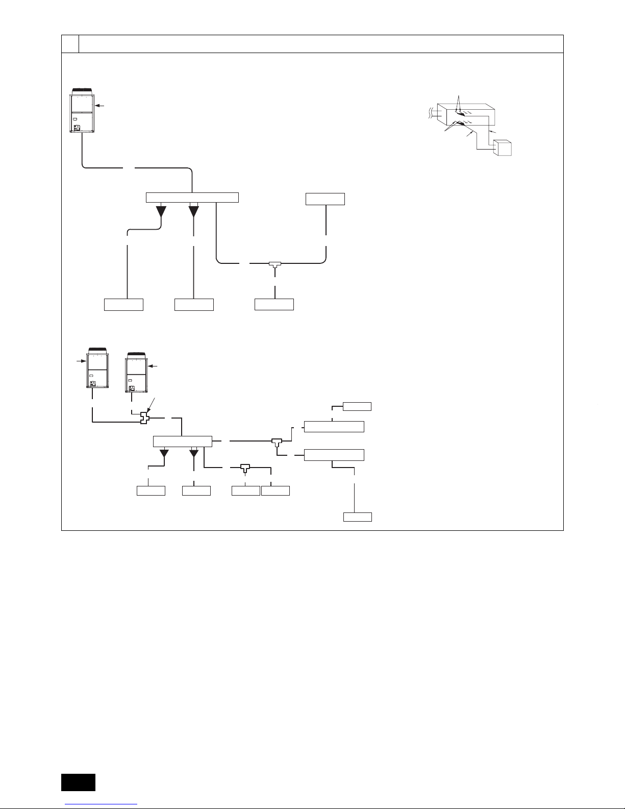
9.2. Refrigerant piping system
Connection example
[Fig. 9.2.1] (P.4)
Outdoor model High-pressure side
Low-pressure side Total capacity of indoor units
Liquid pipe Gas pipe
High-pressure gas pipe Low-pressure gas pipe
Liquid pipe
Model number
Outdoor twinning kit
A
Outdoor unit
B
BC controller (standard)
C
BC controller (main)
D
BC controller (sub)
E
Indoor unit (15 ~ 80)
F
Indoor unit (100 ~ 250)
G
Outdoor twinning kit
*1 The pipe sizes listed in columns A1 to A2 in this table correspond to the sizes
for the models listed in the unit 1 and 2 columns. When the order of unit 1 and
2 is changed, make sure to use the appropriate pipe size for the model.
Precautions for outdoor unit combinations
Refer to [Fig. 9.2.2] for the positioning of twinning pipes.
[Fig. 9.2.2] (P.6)
<A> The piping from the outdoor units to twinning pipe must be made to slope
downwards the twinning pipe. (high-pressure side only)
<B> Slope of twinning pipes (high-pressure side only)
Make sure the slope of the twinning pipes are at an angle within ±15° to the
ground.
If the slope exceeds the specifi ed angle, the unit may be damaged.
<C> Pipe connection example
The distributor on the low-pressure side must be placed in the outdoor
unit that has a larger capacity index of the two, regardless of the relative
positions of the outdoor units or their addresses.
(If outdoor units that have the same capacity are used in combination, the
distributor can be placed in either outdoor unit.)
If the distributor is placed in the outdoor unit that has a smaller capacity,
refrigerant will not be properly distributed and compressor failure may result.
A
Downward slope
B
Upward slope
C
BC controller
D
Twinning pipe
E
Slope of the twinning pipe is at an angle within ±15° to the ground
F
Twinning pipe (low-pressure side)GTwinning pipe (high-pressure side)
H
On-site piping (low-pressure connecting pipe: between outdoor units)
I
On-site piping (low-pressure main pipe: to BC controller)
J
On-site piping (high-pressure main pipe: to BC controller)
K
Straight run of pipe that is 500 mm or more
Caution:
Do not install traps other than the ones between outdoor units
described on a separate sheet to prevent oil backfl ow and compressor
start-up failure.
Do not install solenoid valves to prevent oil backfl ow and compressor
start-up failure.
Do not install a sight glass because it may show improper refrigerant
fl ow.
If a sight glass is installed, inexperienced technicians that use the
glass may overcharge the refrigerant.
•
•
•
17
GB
10. Additional refrigerant charge
At the time of shipping, the outdoor unit is charged with refrigerant.
This charge does not include the amount needed for extended piping and
additional charging of each refrigerant line will be required on site. In order that
future servicing may be properly provided, always keep a record of the size and
length of each refrigerant line and the amount of additional charge by writing it in
the space provided on the outdoor unit.
10.1. Calculation of additional refrigerant
charge
Calculate the amount of additional charge based on the length of the piping
extension and the size of the refrigerant line.
Use the table below as a guide for calculating the amount of additional
charging and then charge the system accordingly.
If the calculation results in a fraction of less than 0.1 kg, round up to the next
0.1 kg. For example, if the result of the calculation was 30.73 kg, round the
result up to 30.8 kg.
•
•
•
<Additional charge>
Additional refrigerant
charge
=
High-pressure
pipe size
Total length of ø28.58
×0.36
+
High-pressure
pipe size
Total length of ø22.2
×0.23
+
High-pressure
pipe size
Total length of ø19.05
×0.16
+
High-pressure
pipe size
Total length of ø15.88
×0.11
+
Liquid Piping Size
Total length of ø15.88
×0.2
(kg) (m)×0.36(kg/m) (m)×0.23(kg/m) (m)×0.16(kg/m) (m)×0.11(kg/m) (m)×0.2(kg/m)
+
Liquid Piping Size
Total length of ø12.7
×0.12
+
Liquid Piping Size
Total length of ø9.52
×0.06
+
Liquid Piping Size
Total length of ø6.35
×0.024
(m)×0.12(kg/m) (m)×0.06(kg/m) (m)×0.024(kg/m)
+
Total Outdoor Unit
Model Name
BC controller
(Standard/Main)
Per Unit
+
BC controller
(Main) HA-type
+
BC controller
(Sub) Total Units
BC controller
(Sub) Per Unit
+
Total Capacity of
Connected Indoor Units
Per Indoor
Unit
~80
2.0kg
(E)P200 2.0kg
2.0 kg
1 1.0 kg
81~160 2.5kg
(E)P250~(E)P500 3.0kg 161~330 3.0kg
(E)P550~(E)P900 5.0kg
2 2.0 kg
331~390 3.5kg
391~480 4.5kg
481~630 5.0kg
631~710 6.0kg
711~800 8.0kg
801~890 9.0kg
891~1070 10.0kg
1071~1250 12.0kg
1251~
14.0kg
<Example>
Indoor 1: 80 A: ø28.58 40 m a: ø9.52 10 m
At the
conditions
below:
2: 250 B: ø9.52 10 m b: ø9.52 5 m
3: 32 C: ø9.52 20 m c: ø6.35 5 m
4: 40 D: ø9.52 5 m d: ø6.35 10 m
5: 32 E: ø9.52 5 m e: ø6.35 5 m
6: 63 F: ø22.2 3 m f: ø9.52 5 m
G: ø19.05 1 m
Outdoor P550
The total length of each liquid line is as follows:
ø28.58: A = 40 m
ø22.2: F = 3 m
ø19.05: G = 1 m
ø9.52: C + D + E + a + b + f = 50 m
ø6.35: c + d + e = 20 m
Therefore,
<Calculation example>
Additional refrigerant charge
= 40 × 0.36 + 3 × 0.23 + 1 × 0.16 + 50 × 0.06 + 20 × 0.024 + 5 + 2 + 5
= 30.8 kg
Limitation of the amount of refrigerant to be charged
The above calculation result of the amount of refrigerant to be charged must become below the value in the table below.
Outdoor unit model P200 P250 P300 P350 P400 P450 P500 P550 P600 P650 P700 P750 P800 P850 P900
Maximum amount of
refrigerant *1 kg
24.8kg 33.8kg 34.8kg 39.7kg 46.7kg 53.7kg 60.2kg 69.2kg 72.9kg 74.6kg 90.3kg 91.5kg 91.5kg 91.5kg 91.5kg
Outdoor unit model
EP200 EP250 EP300 EP350 EP400 EP450 EP500 EP550 EP600 EP650 EP700
Maximum amount of
refrigerant *1 kg
27.3kg 34.0kg 35.0kg 39.7kg 47.5kg 49.2kg 62.9kg 69.6kg 73.3kg 74.8kg 74.8kg
*1 Amount of additional refrigerant to be charged on site
•
18
GB
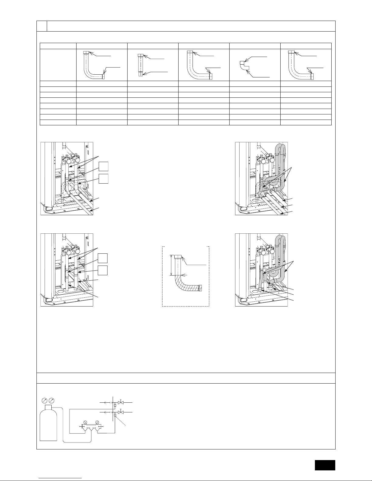
<Refrigerant piping connection examples>
[Fig.10.2.2] (P.7)
1
Connecting pipe (ID ø25.4, ID ø22.2) <Included with outdoor unit>
2
Connecting pipe (ID ø25.4, OD ø19.05) <Included with outdoor unit>
3
Connecting pipe (ID ø25.4, ID ø28.58) <Included with outdoor unit>
4
Connecting elbow (ID ø19.05, OD ø19.05) <Included with outdoor unit>
5
Connecting elbow (ID ø28.58, OD ø28.58) <Included with outdoor unit>
<A> Front pipe routing <B> Bottom pipe routing
<C> Low-pressure side <D> High-pressure side
<E> Severing portion referral fi gure
A
Shape
B
When not attaching a low-pressure twinning pipe
C
When attaching a low-pressure twinning pipe
D
Refrigerant service valve piping
E
On-site piping (low-pressure connecting pipe)
F
On-site piping (high-pressure connecting pipe)
G
Twinning kit (sold separately)
H
On-site piping (low-pressure connecting pipe: to BC controller)
I
On-site piping (low-pressure connecting pipe: to outdoor unit)
J
75 mm (reference measurement)
K
ID ø25.4 side
L
Severing portion
*1 For the attachment of the Twinning pipe (sold separately), refer to
the instructions included in the kit.
*2 Connection pipe is not used when the Twinning Kit is attached.
*3 Use a pipe cutter to sever.
Front pipe routing
P200, EP200
P250, P300
EP250, EP300,
P350, EP350
P400, P450
: Expand the high-pressure side on-site piping
(IDø15.88) and connect to the refrigerant service
valve piping.
: Expand the high-pressure side on-site piping
(IDø19.05) and connect to the refrigerant service
valve piping.
: Use the included connecting pipe 2 and elbow
4 to connect.
: Use the included connecting pipe 1 to connect.
P200, EP200
P250, P300,
EP250, EP300
P350, P400
EP350, P450
: Expand the low-pressure side on-site piping
(IDø19.05) and connect to the refrigerant service
valve piping.
: Use the included connecting pipe 1 to connect.
: Use the included connecting pipe 3 to connect.
: Use the included connecting elbow 5 to connect.
Bottom pipe routing
P200, EP200
P250, P300
EP250, EP300,
P350, EP350
P400, P450
: Expand the high-pressure side on-site piping
(IDø15.88) and connect to the refrigerant service
valve piping.
: Expand the high-pressure side on-site piping
(IDø19.05) and connect to the refrigerant service
valve piping.
: Use the included connecting pipe 2. Expand the
on-site piping to connect to ID ø 19.05.
: Sever the included connecting pipe 1 as shown
in the fi gure with a pipe cutter to use. Expand the
on-site piping to connect to ID ø 22.2.
P200, EP200
P250, P300,
EP250, EP300
P350, P400
EP350, P450
: Expand the low-pressure side on-site piping
(IDø19.05) and connect to the refrigerant service
valve piping.
: Sever the included connecting pipe 1 as shown
in the fi gure with a pipe cutter to use. Expand the
on-site piping to connect to IDø22.2.
: Sever the included connecting pipe 3 as shown
in the fi gure with a pipe cutter to use. Expand the
on-site piping to connect to IDø28.58.
: Expand the low-pressure side on-site piping
(IDø28.58) and connect to the refrigerant service
valve piping.
Satisfy the minimum insertion depth in the table below when expanding on-site
piping
Pipe diameter (mm) Minimum insertion depth (mm)
5 or more less than 8 6
8 or more less than 12 7
12 or more less than 16 8
16 or more less than 25 10
25 or more less than 35 12
35 or more less than 45 14
•
•
10.2. Precautions concerning piping
connection and valve operation
Conduct piping connection and valve operation accurately and carefully.
Removing the pinched connecting pipe
When shipped, a pinched connecting pipe is attached to the on site highpressure and low-pressure valves to prevent gas leakage.
Take the following steps 1 through 4 to remove the pinched connecting
pipe before connecting refrigerant pipes to the outdoor unit.
1 Check that the refrigerant service valve is fully closed (turned clockwise
all the way).
2 Connect a charging hose to the service port on the low-pressure/
high-pressure refrigerant service valve, and extract the gas in the
pipe section between the refrigerant service valve and the pinched
connecting pipe.
3 After vacuuming gas from the pinched connecting pipe, sever the
pinched connecting pipe at the location shown in [Fig.10.2.1] and drain
the refrigerant.
4 After completing 2 and 3 heat the brazed section to remove the
pinched connecting pipe.
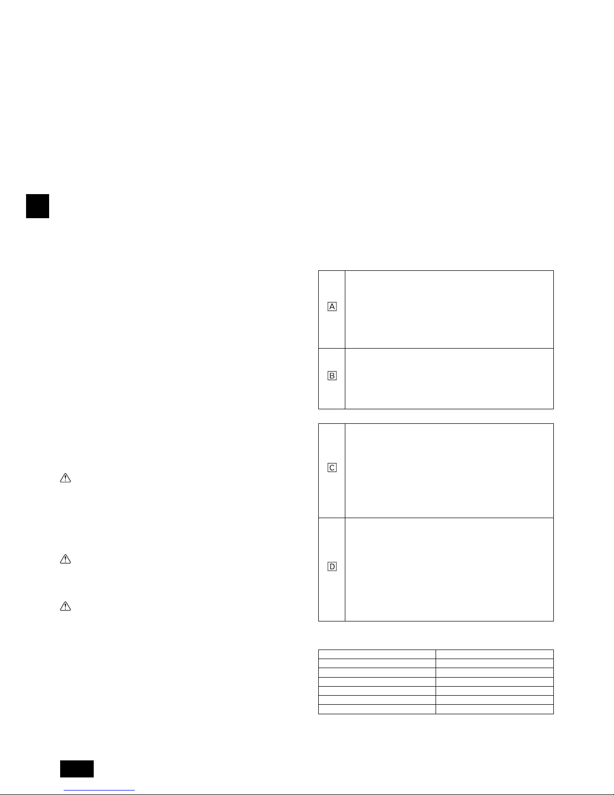
[Fig. 10.2.1] (P.6)
<A> Refrigerant service valve (high-pressure side/brazed type)
<B> Refrigerant service valve (low-pressure side/brazed type)
A
Shaft
Fully closed at the factory, when connecting the piping, and when
vacuuming. Open fully after these operations are completed.
<When opening>
• Turn the shaft counterclockwise with a hexagonal wrench.
• Turn around the shaft until it stops.
<When closing>
• Turn the shaft clockwise with a hexagonal wrench.
• Turn around the shaft until it stops.
B
Shaft
Fully closed at the factory, when connecting the piping, and when
vacuuming. Open fully after these operations are completed.
<When opening>
• Turn the shaft counterclockwise.
• Turn around the shaft until it stops.
<When closing>
• Turn the shaft clockwise.
• Turn around the shaft until it stops.
C
Stopper pin
Prevents the shaft from turning 90° or more.
D
Service port
Available for gas venting of the pinched connecting pipe, or vacuuming in the
refrigerant pipes on the site.
E
Cap
Remove the cap before operating the shaft. Be sure to return it to the original
position after completing the operation.
F
Pinched connecting pipe severing portion
G
Pinched connecting pipe brazing portion
Warning:
The sections between the refrigerant service valves and the pinched
connecting pipes are fi lled with gas and refrigerant oil. Extract the gas
and refrigerant oil in the above-mentioned pipe section before heating
the brazed section to remove the refrigerant service valve pinched
connecting pipe.
- If the brazed section is heated without fi rst extracting the gas and
refrigerant oil, the pipe may burst or the pinched connecting pipe may blow
off and ignite the refrigerant oil, causing serious injury.
Caution:
Place a wet towel on the refrigerant service valve before heating the brazed
section to keep the temperature of the valve from exceeding 120 ˚C.
Direct the fl ame away from the wiring and metal sheets inside the unit
to prevent heat damage.
Caution:
Do not vent R410A into the atmosphere.
R410A is a Fluorinated Greenhouse gas, covered by the Kyoto
Protocol, with a Global Warming Potential (GWP) = 1975.
Refrigerant pipe connection
This product includes connecting pipes for front piping and bottom postpiping. (Refer to [Fig.10.2.2])
Check the high-pressure/low-pressure piping dimensions before connecting
the refrigerant pipe.
Refer to item 9.2 Refrigerant piping system for piping dimensions.
Make sure that the refrigerant pipe is not touching other refrigerants pipes,
unit panels, or base plates.
Be sure to use non-oxidative brazing when connecting pipes.
Be careful not to burn the wiring and plate when brazing.
•
•
•
•
•
•
•
•
19
GB
After evacuation and refrigerant charging, ensure that the handle is fully
open. If operating with the valve closed, abnormal pressure will be imparted
to the high- or low-pressure side of the refrigerant circuit, giving damage to
the compressor, four-way valve, etc.
Determine the amount of additional refrigerant charge by using the formula,
and charge refrigerant additionally through the service port after completing
piping connection work.
After completing work, tighten the service port and cap securely so as not to
generate any gas leakage. (Refer to the table on the below for appropriate
tightening torque.)
Appropriate tightening torque:
Outer
diameter of
copper pipe
(mm)
Cap (N·m) Shaft (N·m)
Size of
hexagonal
wrench
(mm)
Service port
(N·m)
ø9.52 15 6 4
12
ø12.7 20 9 4
ø15.88 25 15 6
ø19.05 25 30 8
ø25.4 25 30 8
ø28.58 25 – – 16
Caution:
Keep the valve closed until refrigerant charging to the pipes to be
added on site has been completed. Opening the valve before charging
the refrigerant may cause damage to the unit.
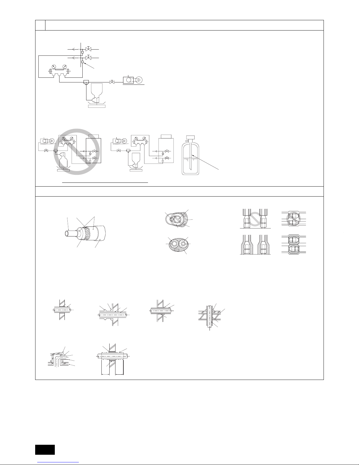
Do not use a leak detection additive.
[Fig. 10.2.3] (P.6)
A Example of closure materials (fi eld supply)
B Fill the gap at the site
*When not attaching a low-pressure twinning pipe.
•
•
•
•
•
Make sure to seal-off the space around areas where the wires and refrigerant
pipes enter the unit to ensure that small animals, rainwater, or snow cannot
enter the unit through such openings and cause damage to the unit.
Caution:
Make sure to seal-off the openings for the pipe and wire retrieval.
Small animals, rainwater, or snow entering through the openings may
cause damage to the device.
10.3. Airtight test, evacuation, and
refrigerant charging
1 Airtight test
Perform with the valve of the outdoor unit closed, and pressurize the
connection piping and the indoor unit from the service port provided on the
valve of the outdoor unit. (Always pressurize from both the high-pressure
pipe and the low-pressure pipe service ports.)
[Fig. 10.3.1] (P.7)
A
Nitrogen gas
B
To indoor unit
C
System analyzer
D
Low knob
E
Hi knob
F
Val ve
G
Low-pressure pipe
H
High-pressure pipe
I
Outdoor unit
J
Service port
Observe the following restrictions when conducting an air tightness test
to prevent negative effects on the refrigerating machine oil. Also, with
nonazeotropic refrigerant (R410A), gas leakage causes the composition to
change and affects performance. Therefore, perform the airtightness test
cautiously.
•
Caution:
Only use refrigerant R410A.
- The use of other refrigerants such as R22 or R407C, which contains chlorine,
will deteriorate the refrigerating machine oil or cause the compressor to
malfunction.
2 Evacuation
Evacuate with the valve of the outdoor unit closed and evacuate both the
connection piping and the indoor unit from the service port provided on the
valve of the outdoor unit using a vacuum pump. (Always evacuate from the
service port of both the high-pressure pipe and the low-pressure pipe.) After
the vacuum reaches 650 Pa [abs], continue evacuation for at least one hour
or more. Then, stop the vacuum pump and leave it for 1 hour. Ensure the
degree of vacuum has not increased. (If the degree of vacuum increase
is larger than 130 Pa, water might have entered. Apply pressure to dry
nitrogen gas up to 0.05 MPa and vacuum again.) Finally, seal in with the
liquid refrigerant through the high-pressure pipe, and adjust the low-pressure
piping to obtain an appropriate amount of the refrigerant during operation.
* Never perform air purging using refrigerant.
[Fig. 10.3.2] (P.8)
A
System analyzer
B
Low knob
C
Hi knob
D
Valve
E
Low-pressure pipe
F
High-pressure pipe
G
Service port
H
Three-way joint
I
Val ve
J
Valve
K
R410A cylinder
L
Scale
M
Vacuum pump
N
To indoor unit
O
Outdoor unit
Note:
Always add an appropriate amount of refrigerant. Also always charge
the system with liquid refrigerant.
Use a gauge manifold, charging hose, and other parts for the
refrigerant indicated on the unit.
Use a graviometer. (One that can measure down to 0.1 kg.)
Use a vacuum pump with a reverse fl ow check valve.
(Recommended vacuum gauge: ROBINAIR 14830A Thermistor Vacuum
Gauge)
Also use a vacuum gauge that reaches 65 Pa [abs] or below after
operating for fi ve minutes.
3 Refrigerant Charging
Since the refrigerant used with the unit is nonazerotropic, it must be charged
in the liquid state. Consequently, when charging the unit with refrigerant from
a cylinder, if the cylinder does not have a syphon pipe, charge the liquid
refrigerant by turning the cylinder upside-down as shown in Fig.10.3.3. If
the cylinder has a syphon pipe like that shown in the picture on the right,
the liquid refrigerant can be charged with the cylinder standing upright.
Therefore, give careful attention to the cylinder specifi cations. If the unit
should be charged with gas refrigerant, replace all the refrigerant with new
refrigerant. Do not use the refrigerant remaining in the cylinder.
[Fig. 10.3.3] (P.8)
A
Syphon pipe
B
In case of the R410A cylinder having no syphon pipe.
•
•
•
•
Airtight test procedure Restriction
(1) After pressurizing to the design pressure (4.15 MPa) using nitrogen gas, allow it to
stand for about one day. If the pressure does not drop, airtightness is good.
However, if the pressure drops, since the leaking point is unknown, the following
bubble test may also be performed.
(2) After the pressurization described above, spray the fl are connection parts, brazed
parts, and other parts that may leak with a bubbling agent (Gupofl ex, etc.) and visually
check for bubbles.
(3) After the airtight test, wipe off the bubbling agent.
If a fl ammable gas or air (oxygen) is used as the pressurization
gas, it may catch fi re or explode.
•
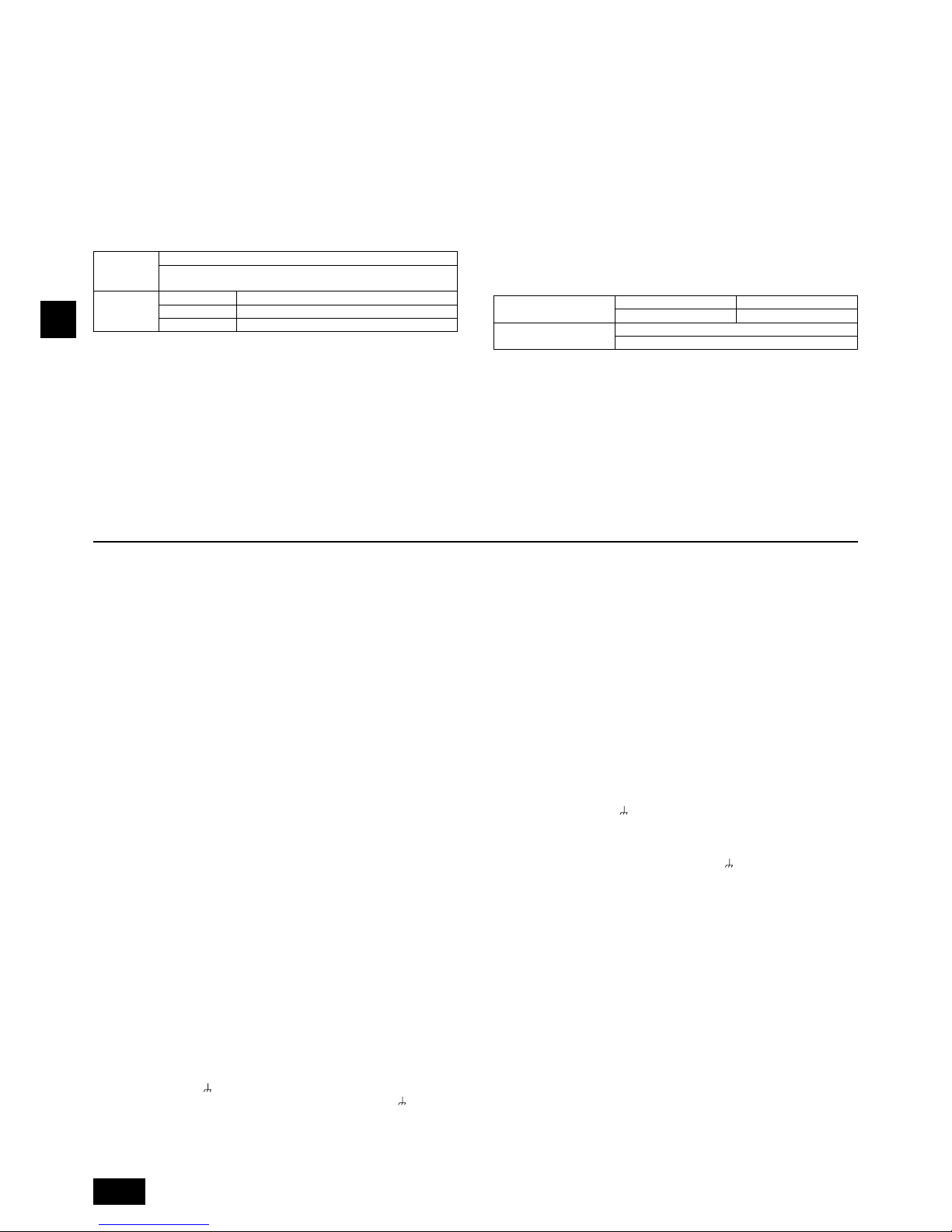
20
GB
11.1. Caution
1 Follow ordinance of your governmental organization for technical standard
related to electrical equipment, wiring regulations and guidance of each
electric power company.
2 Wiring for control (hereinafter referred to as transmission line) shall be (5
cm or more) apart from power source wiring so that it is not infl uenced by
electric noise from power source wiring (Do not insert transmission line and
power source wire in the same conduit).
3 Be sure to provide designated grounding work to the outdoor unit.
4 Give some allowance to wiring for the electrical control box on the indoor
and outdoor units, because these boxes are sometimes removed at the time
of service work.
5 Never connect the main power source to the terminal block of the
transmission line. If connected, electrical parts will burn out.
6 Use 2-core shield cable for the transmission line. If transmission lines of
different systems are wired with the same multiplecore cable, the resultant
poor transmitting and receiving will cause erroneous operations.
7 Only the transmission line specifi ed should be connected to the terminal
block for outdoor unit transmission.
Erroneous connection does not allow the system to operate.
8 In the case of connecting with an upper class controller or to conduct group
operation in different refrigerant systems, the control line for transmission is
required between the outdoor units in different refrigerant systems.
Connect this control line between the terminal blocks for centralized control
(2-wire line with no polarity).
9 Grouping is set by operating the remote controller.
11.2. Control box and connecting position
of wiring
1 Outdoor unit
1. Remove the front panel of the control box by removing the 4 screws and
pushing it up a little before pulling it out.
2. Connect the indoor - outdoor transmission line to the terminal block (TB3) for
the indoor - outdoor transmission line.
If multiple outdoor units are connected in the same refrigerant system, daisy-
chain TB3 (M1, M2,
Terminal) on the outdoor units. Connect the indoor -
outdoor transmission line for the outdoor units to TB3 (M1, M2,
Terminal)
of only one of the outdoor units.
3. Connect the transmission lines for centralized control (between the
centralized control system and the outdoor unit of different refrigerant
systems) to the terminal block for centralized control (TB7). If the multiple
outdoor units are connected to the same refrigerant system, daisy-chain TB7
(M1, M2, S Terminal) on the outdoor units in the same refrigerant system.
(*1)
*1: If TB7 on the outdoor unit in the same refrigerant system is not daisy-
chained, connect the transmission line for centralized control to TB7 on
the OC (*2). If the OC is out of order, or if the centralized control is being
conducted during the power supply shut-off, daisy-chain TB7 on the OC
and OS (In the case that the outdoor unit whose power supply connector
CN41 on the control board has been replaced with CN40 is out of order
or the power is shut-off, centralized control will not be conducted even
when TB7 is daisy-chained).
*2: OC and OS of the outdoor units in the same refrigerant system are
automatically identifi ed. They are identifi ed as OC and OS in descending
order of capacity (If the capacity is the same, they will be in ascending
order of their address number).
4. In the case of indoor-outdoor transmission line, connect the shield ground to
the grounding terminal (
). In the case of transmission lines for centralized
control, connect it to the shield terminal (S) on the terminal block for
centralized control (TB7). Furthermore, in the case of the outdoor units
whose power supply connector CN41 is replaced with CN40, short circuit the
shield terminal (S) and the grounding terminal (
) in addition to the above.
5. Fix the connected wires securely in place with the cable strap at the bottom
of the terminal block. External force applied to the terminal block may
damage it resulting in a short circuit, ground fault, or a fi re.
[Fig. 11.2.1] (P.9)
A
Power source
B
Transmission line
C
Earth screw
[Fig. 11.2.2] (P.9)
A
Cable strap
B
Power source cable
C
Transmission cable
D
Pillar
2 Conduit tube installation
Open by hammering the knockout holes for the conduit tube located on the
base and the bottom part of the front panel.
When installing the conduit tube directly through the knockout holes, remove
the burr and protect the tube with masking tape.
Use the conduit tube to narrow down the opening if there is a possibility of
small animals entering the unit.
When taking the conduit tube out from the bottom part of the unit, caulk
around the tube opening to prevent water penetration.
•
•
•
•
11. Wiring (For details, refer to the installation manual of each unit and controller.)
Penetrations
[Fig. 10.4.4] (P.8)
<A> Inner wall (concealed) <B> Outer wall
<C> Outer wall (exposed) <D> Floor (waterproofi ng)
<E> Roof pipe shaft
<F> Penetrating portion on fi re limit and boundary wall
A
Sleeve
B
Heat insulating material
C
Lagging
D
Caulking material
E
Band
F
Waterproofi ng layer
G
Sleeve with edge
H
Lagging material
I
Mortar or other incombustible caulking
J
Incombustible heat insulation material
When fi lling a gap with mortar, cover the penetration part with steel plate so
that the insulation material will not be caved in. For this part, use incombustible
materials for both insulation and covering. (Vinyl covering should not be used.)
Insulation materials for the pipes to be added on site must meet the following
specifi cations:
Outdoor unit
-BC controller
High-pressure pipe 10 mm or more
Low-pressure pipe 20 mm or more
BC controller
-indoor unit
Pipe size 6.35 mm to 25.4 mm 10 mm or more
Pipe size 28.58 mm to 38.1 mm 15 mm or more
* Installation of pipes in a high-temperature high-humidity environment, such
as the top fl oor of a building, may require the use of insulation materials
thicker than the ones specifi ed in the chart above.
* When certain specifi cations presented by the client must be met, ensure that
they also meet the specifi cations on the chart above.
•
10.4. Thermal insulation of refrigerant
piping
Be sure to add insulation work to refrigerant piping by covering high-pressure
pipe and low-pressure pipe separately with enough thickness heat-resistant
polyethylene, so that no gap is observed in the joint between indoor unit and
insulating material, and insulating materials themselves. When insulation work is
insuffi cient, there is a possibility of condensation drip, etc. Pay special attention
to insulation work in the ceiling plenum.
[Fig. 10.4.1] (P.8)
A
Steel wire
B
Piping
C
Asphaltic oily mastic or asphalt
D
Heat insulation material A
E
Outer covering B
Heat
insulation
material A
Glass fi ber + Steel wire
Adhesive + Heat - resistant polyethylene foam + Adhesive tape
Outer
covering B
Indoor Vinyl tape
Floor exposed Water-proof hemp cloth + Bronze asphalt
Outdoor Water-proof hemp cloth + Zinc plate + Oily paint
Note:
When using polyethylene as a covering material, asphalt roofi ng shall
not be required.
No heat insulation must be provided to electric wires.
[Fig. 10.4.2] (P.8)
A
High-pressure pipeBLow-pressure pipeCElectric wire
D
Finishing tape
E
Insulator
[Fig. 10.4.3] (P.8)
•
•
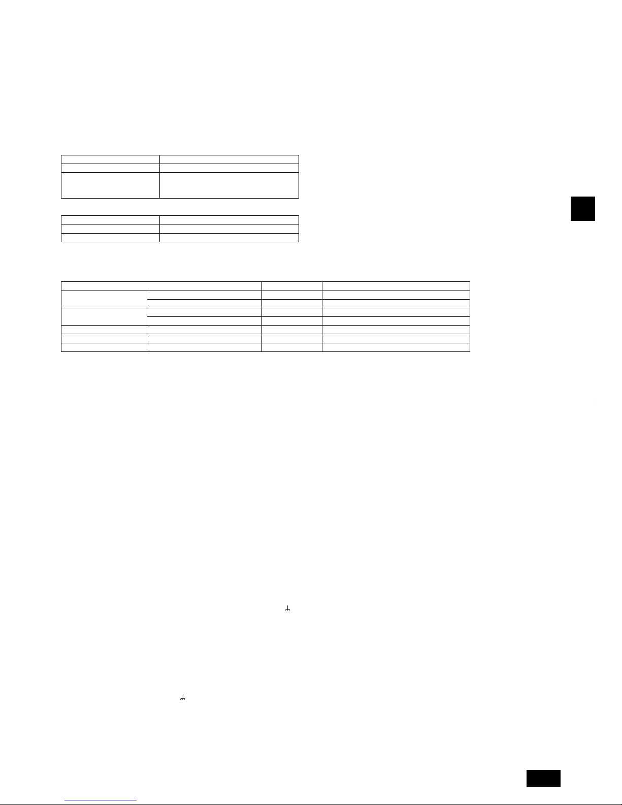
21
GB
11.3. Wiring transmission cables
1 Types of control cables
1. Wiring transmission cables
Types of transmission cables: Shielding wire CVVS, CPEVS or MVVS
Cable diameter: More than 1.25 mm
2
Maximum wiring length: Within 200 m
Maximum length of transmission lines for centralized control and indoor/outdoor transmission lines (Maximum length via outdoor units): 500 m MAX
The maximum length of the wiring between power supply unit for transmission lines (on the transmission lines for centralized control) and each outdoor unit and
system controller is 200 m.
2. Remote control cables
ME Remote Controller
Kind of remote control cable Sheathed 2-core cable (unshielded) CVV
Cable diameter 0.3 to 1.25 mm
2
(0.75 to 1.25 mm2)*
Remarks
When 10 m is exceeded, use cable with
the same specifi cations as 1. Wiring
transmission cables.
MA Remote Controller
Kind of remote control cable Sheathed 2-core cable (unshielded) CVV
Cable diameter 0.3 to 1.25 mm
2
(0.75 to 1.25 mm2)*
Remarks Within 200 m
* Connected with simple remote controller.
2 Wiring examples
Controller name, symbol and allowable number of controllers.
Name Code Possible unit connections
Outdoor unit Main unit OC – (*2)
Sub unit OS – (*2)
BC controller Main unit BC One controller for one OC
Sub unit BS Zero, one or two controllers for one OC
Indoor unit Indoor unit controller IC 1 to 50 units per 1 OC (*1)
Remote controller Remote controller (*1) RC 2 units maximum per group
Other Transmission booster unit RP 0 to 2 units per 1 OC (*1)
*1 A transmission booster (RP) may be required depending on the number of connected indoor unit controllers.
*2 OC and OS of the outdoor units in the same refrigerant system are automatically identifi ed. They are identifi ed as OC and OS in descending order of capacity. (If the
capacity is the same, they will be in ascending order of their address number.)
Example of a group operation system with multiple outdoor units (Shielding wires and address setting are
necessary.)
<Examples of transmission cable wiring>
[Fig. 11.3.1] ME Remote Controller (P.9)
*1: When the power supply unit is not connected to the transmission line for centralized control, disconnect the male power supply connector (CN41) from ONE
outdoor unit in the system and connect it to CN40.
*2: If a system controller is used, set SW2-1 on all of the outdoor units to ON.
[Fig. 11.3.2] MA Remote Controller (P.10)
<A> Change the jumper connector from CN41 to CN40
<B> SW2-1:ON
<C> Keep the jumper connector on CN41
A
Group 1
B
Group 3
C
Group 5
D
Shielded wire
E
Sub remote controller
( ) Address
[Fig. 11.3.3] Combination of outdoor units and transmission booster unit (P.10)
( ) Address
Daisy-chain terminals (TB3) on outdoor units in the same refrigerant system together.
Leave the power jumper connector on CN41 as it is. When connecting a system controller to the transmission line (TB7) for centralized control, refer to
[Fig. 11.3.1], [Fig. 11.3.2], or DATA BOOK.
<Wiring Method and Address Settings>
a. Always use shielded wire when making connections between the outdoor unit (OC) and the indoor unit (IC), as well for all OC-OC, OC-OS and IC-IC wiring intervals.
b. Use feed wiring to connect terminals M1 and M2 and the earth terminal
on the transmission line terminal block (TB3) of each outdoor unit (OC) to terminals M1,
M2 and terminal S on the transmission line block of the indoor unit (IC). For OC and OS, connect TB3 to TB3.
c. Connect terminals 1 (M1) and 2 (M2) on the transmission line terminal block of the indoor unit (IC) that has the most recent address within the same group to the
terminal block on the remote controller (RC).
d. Connect together terminals M1, M2 and terminal S on the terminal block for central control (TB7) for the outdoor unit in a different refrigerant system (OC). For OC
and OS in the same refrigerant system, connect TB7 to TB7.
e. When the power supply unit is not installed on the central control transmission line, change the jumper connector on the control board from CN41 to CN40 on only
one outdoor unit in the system.
f. Connect the terminal S on the terminal block for central control (TB7) for the outdoor unit (OC) for the unit into which the jumper connector was inserted into CN40 in
the step above to the earth terminal
in the electrical component box.
g. Set the address setting switch as follows.
* To set the outdoor unit address to 100, the outdoor address setting switch must be set to 50.
•
•
•
•
•
•
•
•
•
•
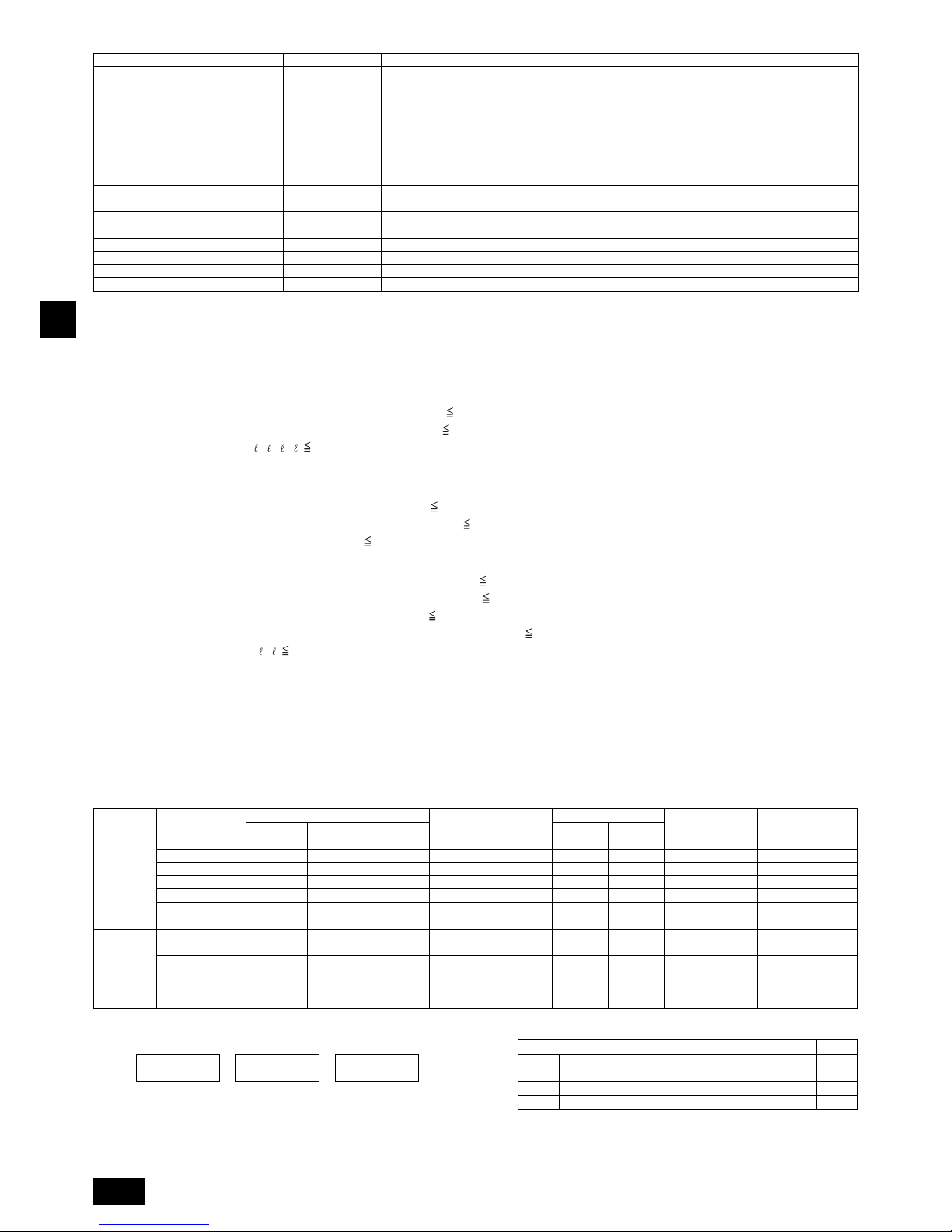
22
GB
Unit Range Setting Method
Indoor unit (Main) 01 to 50 Use the most recent address within the same group of indoor units. With an R2 system with sub BC
controllers, set the indoor unit address in the following order:
1 Indoor units connected to the main BC controller
2 Indoor units connected to BC sub controller 1
3 Indoor units connected to BC sub controller 2
Set the indoor unit addresses so that all the addresses of 1 are smaller than those of 2, and that all
the addresses of 2 are smaller than those of 3.
Indoor unit (Sub)
01 to 50 Use an address, other than that of the IC (Main) from among the units within the same group of indoor
units. This must be in sequence with the IC (Main)
Outdoor Unit (OC, OS)
51 to 100 Set the addresses of the outdoor units in the same refrigerant system in the order of sequential
number. OC and OS are automatically identifi ed. (*1)
BC controller (Main)
51 to 100 Outdoor unit address plus 1. When the set indoor unit address duplicates the address of another
indoor unit, set the new address to a vacant address within the setting range.
BC controller (Sub) 51 to 100 Lowest address within the indoor units connected to the BC controller (sub) plus 50
ME R/C (Main) 101 to 150 Set at an IC (Main) address within the same group plus 100
ME R/C (Sub) 151 to 200 Set at an IC (Main) address within the same group plus 150
MA R/C – Unnecessary address setting (Necessary main/sub setting)
h. The group setting operations among the multiple indoor units is done by the remote controller (RC) after the electrical power has been turned on.
i. When the centralized remote controller is connected to the system, set centralized control switches (SW2-1) on control boards in all outdoor units (OC, OS) to “ON”.
*1 OC and OS of the outdoor units in the same refrigerant system are automatically identifi ed. They are identifi ed as OC and OS in descending order of capacity (If the
capacity is the same, they are identifi ed in the ascending order of their address number).
<Permissible Lengths>
1 ME Remote controller [Fig. 11.3.1] (P.9)
Max length via outdoor units: L
1+L2+L3+L4 and L1+L2+L3+L5 and L1+L2+L6 500 m (1.25 mm
2
or more)
Max transmission cable length: L
1 and L3+L4 and L3+L5 and L6 and L2+L6 200 m (1.25 mm
2
or more)
Remote controller cable length:
1, 2, 3, 4 10 m (0.3 to 1.25 mm
2
)
If the length exceeds 10 m, use a 1.25 mm
2
shielded wire. The length of this section (L8) should be included in the calculation of the
maximum length and overall length.
2 MA Remote controller [Fig. 11.3.2] (P.10)
Max length via outdoor unit (M-NET cable): L
1+L2+L3+L4 and L1+L2+L6 500 m (1.25 mm
2
or more)
Max transmission cable length (M-NET cable): L
1 and L3+L4 and L6 and L2+L6 200 m (1.25 mm
2
or more)
Remote controller cable length: m
1+m2 and m1+m2+m3+m4 200 m (0.3 to 1.25 mm
2
)
3 Transmission booster [Fig. 11.3.3] (P.10)
Max transmission cable length (M-NET cable): 1 L
11 + L12 + L13 + L14 + L16 + L17 200 m (1.25 mm
2
)
2 L
11 + L12 + L13 + L14 + L16 + L18 200 m (1.25 mm
2
)
3 L
11 + L12 + L13 + L15 200 m (1.25 mm
2
)
4 L
17 + L16 + L14 + L15, L15 + L14 + L16 + L18 200 m (1.25 mm
2
)
Remote controller cable length:
1, 2 10 m (0.3 to 1.25 mm
2
)
If the length exceeds 10 m, use 1.25 mm
2
shielded cable and calculate the length of that portion (L15 and L18) as within the total
extended length and the longest remote length.
11.4. Wiring of main power supply and equipment capacity
Schematic Drawing of Wiring (Example)
[Fig. 11.4.1] (P.10)
A
Switch (Breakers for wiring and current leakage)
B
Breakers for current leakageCOutdoor unit
D
Pull box
E
Indoor unit
F
BC controller (standard or main)
F'
BC controller (sub)
Thickness of wire for main power supply, capacities of the switch and system impedance
Model
Minimum wire thickness (mm
2
)
Breaker for current
leakage
Local swtich (A)
Breaker for wiring
(NFB) (A)
Max. Permissive
System Impedance
Main cable Branch Ground
Capacity Fuse
Outdoor unit
(E)P200YJM 4.0 - 4.0
30A 100mA 0.1sec. or less
25 25 30 *1
(E)P250YJM 4.0 - 4.0
30A 100mA 0.1sec. or less
32 32 30 *1
(E)P300YJM 4.0 - 4.0
30A 100mA 0.1sec. or less
32 32 30 *1
P350YJM 6.0 - 6.0
40A 100mA 0.1sec. or less
40 40 40 0.24Ω
EP350YJM 6.0 - 6.0
40A 100mA 0.1sec. or less
40 40 40 *1
P400YJM 10.0 - 10.0
60A 100mA 0.1sec. or less
63 63 60 0.21Ω
P450YJM 10.0 - 10.0
60A 100mA 0.1sec. or less
63 63 60 0.19Ω
Total
operating
current of
the indoor
unit
F0=20A or less*2
1.5 1.5 1.5 Current sensitivity *3 16 16 20
(apply to
IEC61000-3-3)
F0=30A or less*2
2.5 2.5 2.5 Current sensitivity *3 25 25 30
(apply to
IEC61000-3-3)
F0=40A or less*2
4.0 4.0 4.0 Current sensitivity *3 32 32 40
(apply to
IEC61000-3-3)
*1: Meets technical requirements of IEC61000-3-3
*2: Please take the larger of F1 or F2 as the value for F0.
F1 = Total operating maximum current of the indoor units x 1.2 Indoor unit V1
F2 =
V1 x Quantity
of Type A
+
V1 x Quantity
of Type B
+
V1 x Quantity
of Others
Type A
PLFY-VBM, PMFY-VBM, PEFY-VMS, PCFY-VKM,
PKFY-VHM, PKFY-VKM, PFFY-VKM, PFFY-VLRMM
1.6
Type B PEFY-VMA 3.2
Others Other indoor unit 0
•
•
•
•
•
•
•
•

23
GB
Warning:
Be sure to use specifi ed wires for connections and ensure no external force is imparted to terminal connections. If connections are not fi xed fi rmly,
heating or fi re may result.
Be sure to use the appropriate type of overcurrent protection switch. Note that generated overcurrent may include some amount of direct current.
Caution:
Some installation sites may require attachment of an earth leakage breaker for the inverter. If no earth leakage breaker is installed, there is a danger of
electric shock.
Do not use anything other than a breaker and fuse with the correct capacity. Using a fuse or wire of too large capacity may cause malfunction or fi re.
Note:
This device is intended for the connection to a power supply system with a maximum permissible system impedance shown in the above table at the
interface point (power service box) of the user’s supply.
The user must ensure that this device is connected only to a power supply system which fulfi ls the requirement above.
If necessary, the user can ask the public power supply company for the system impedance at the interface point.
This equipment complies with IEC 61000-3-12 provided that the short-circuit power S
SC
is greater than or equal to S
SC
(*2) at the interface point between
the user’s supply and the public system. It is the responsibility of the installer or user of the equipment to ensure, by consultation with the distribution
network operator if necessary, that the equipment is connected only to a supply with a short-circuit power S
SC
greater than or equal to S
SC
(*2).
S
SC
(*2)
Model S
SC
(MVA)
PURY-(E)P200YJM
1.24
PURY-P250YJM
1.44
PURY-EP250YJM
1.28
PURY-P300YJM
1.73
PURY-EP300YJM
1.55
PURY-P350YJM
2.27
PURY-EP350YJM
1.95
PURY-P400YJM
2.56
PURY-P450YJM
2.93
12. Test run
12.1. The following phenomena do not represent faults.
Phenomenon Display of remote controller Cause
Indoor unit does not perform cooling
(heating) operation.
“Cooling (heating)” fl ashes When another indoor unit is performing the heating (cooling) operation, the
cooling (heating) operation is not performed.
The auto vane rotates and begins to blow air
horizontally.
Normal display If air has been blowing downward for 1 hour during cooling, the unit may
automatically change to horizontal blowing with the control operation of the
auto vane. During defrosting or immediately after heating start-up/shut-down,
the auto vane automatically rotates to blow air horizontally for a short period
of time.
Fan setting changes during heating. Normal display Ultra-low speed operation is commenced at thermostat OFF.
Light air automatically changes over to set value by time or piping temperature
at thermostat ON.
Fan stops during heating operation. Defrost display The fan is set to stop during defrosting.
Fan does not stop while operation has been
stopped.
No lighting The fan is set to run for 1 minute after stopping to exhaust residual heat (only
in heating).
No setting of fan while start SW has been
turned on.
Heat ready Ultra low-speed operation for 5 minutes after SW ON or until piping
temperature becomes 35°C, low speed operation for 2 minutes thereafter, and
then set notch is commenced (Hot adjust control).
Indoor unit remote controller shows “H0”
or “PLEASE WAIT” indicator for about fi ve
minutes when turning ON universal power
supply.
“H0” or “PLEASE WAIT” fl ashes The system is being started up.
Operate remote controller again after “H0” or “PLEASE WAIT” disappears.
Drain pump does not stop when unit is
stopped.
Light out After cooling operation stops, the unit continues to operate drain pump for
three minutes and then stops it.
Drain pump continues to operate while unit
has been stopped.
Unit continues to operate drain pump if drainage is generated, even after the
unit has been stopped.
Indoor unit emits noise when switching from
heating to cooling and vice versa.
Normal display This is a switching sound of the refrigerant circuit and does not imply a
problem.
Immediately after startup, the indoor unit
emits the sound of the refrigerant fl ow.
Normal display Unstable fl ow of the refrigerant emits a sound. This is temporary and does not
imply a problem.
Warm air comes from an indoor unit that is
not performing a heating operation.
Normal display The LEV is slightly open to prevent refrigerant, of the indoor unit that is not
performing the heating operation, from being liquefi ed. This does not imply a
problem.
•
•
•
•
•
•
•
*3: Current sensitivity is calculated using the following formula.
G1 =
V2 x Quantity
of Type 1
+
V2 x Quantity
of Type 2
+
V2 x Quantity
of Others
+ V3 x Wire length [km]
G1 Current sensitivity Indoor unit V2 Wire thickness V3
30mA or less 30mA 0.1sec or less
Type 1
PLFY-VBM, PMFY-VBM, PEFY-VMS, PCFY-VKM,
PKFY-VHM, PKFY-VKM, PFFY-VKM, PFFY-VLRMM
2.4
1.5mm
2
48
100mA or less 100mA 0.1sec or less 2.5mm
2
56
Type 2 PEFY-VMA 1.6 4.0mm
2
66
Others Other indoor unit 0
1. Use dedicated power supplies for the outdoor unit and indoor unit. Ensure OC and OS are wired individually.
2. Bear in mind ambient conditions (ambient temperature,direct sunlight, rain water,etc.) when proceeding with the wiring and connections.
3. The wire size is the minimum value for metal conduit wiring. If the voltage drops, use a wire that is one rank thicker in diameter.
Make sure the power-supply voltage does not drop more than 10%.
4. Specifi c wiring requirements should adhere to the wiring regulations of the region.
5. Power supply cords of parts of appliances for outdoor use shall not be lighter than polychloroprene sheathed fl exible cord (design 245 IEC57).
6. A switch with at least 3 mm contact separation in each pole shall be provided by the Air Conditioner installer.
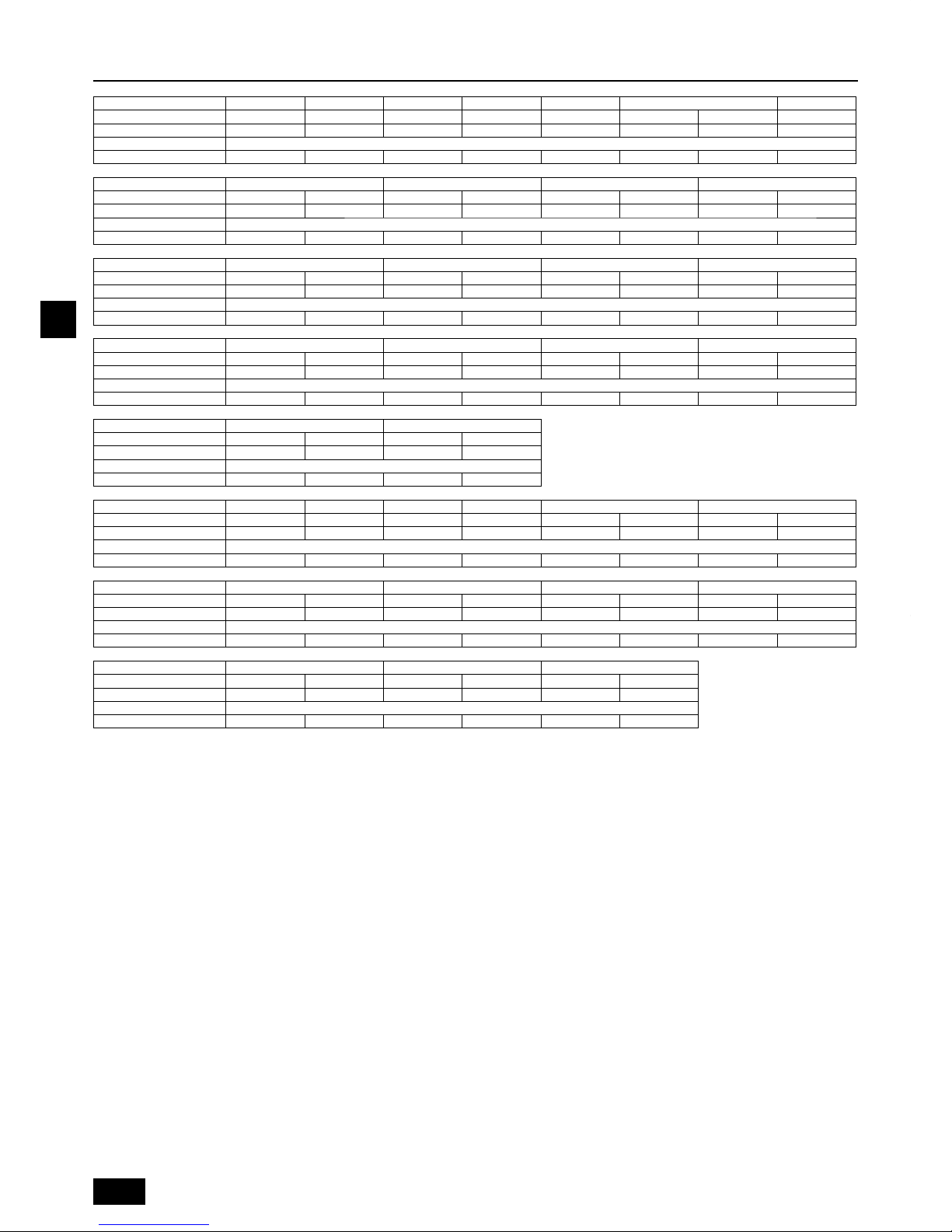
24
GB
13. Information on rating plate
Model P200YJM-A P250YJM-A P300YJM-A P350YJM-A P400YJM-A P400YSJM-A1 P450YJM-A
Unit combination - ----P200YJM-A P200YJM-A Refrigerant (R410A) 9.5kg 9.5kg 9.5kg 11.8kg 11.8kg 9.5kg 9.5kg 11.8kg
Allowable pressure (Ps) HP: 4.15MPa, LP: 2.21MPa
Net weight 240kg 240kg 245kg 270kg 270kg 240kg 240kg 320kg
Model P450YSJM-A1 P500YSJM-A P500YSJM-A1 P550YSJM-A
Unit combination P250YJM-A P200YJM-A P250YJM-A P250YJM-A P300YJM-A P200YJM-A P300YJM-A P250YJM-A
Refrigerant (R410A) 9.5kg 9.5kg 9.5kg 9.5kg 9.5kg 9.5kg 9.5kg 9.5kg
Allowable pressure (Ps) HP: 4.15MPa, LP: 2.21MPa
Net weight 240kg 240kg 240kg 240kg 245kg 240kg 245kg 240kg
Model P600YSJM-A P600YSJM-A1 P650YSJM-A P700YSJM-A
Unit combination P300YJM-A P300YJM-A P350YJM-A P250YJM-A P350YJM-A P300YJM-A P400YJM-A P300YJM-A
Refrigerant (R410A) 9.5kg 9.5kg 11.8kg 9.5kg 11.8kg 9.5kg 11.8kg 9.5kg
Allowable pressure (Ps) HP: 4.15MPa, LP: 2.21MPa
Net weight 245kg 245kg 270kg 240kg 270kg 245kg 270kg 245kg
Model P700YSJM-A1 P750YSJM-A P800YSJM-A P800YSJM-A1
Unit combination P350YJM-A P350YJM-A P400YJM-A P350YJM-A P400YJM-A P400YJM-A P450YJM-A P350YJM-A
Refrigerant (R410A) 11.8kg 11.8kg 11.8kg 11.8kg 11.8kg 11.8kg 11.8kg 11.8kg
Allowable pressure (Ps) HP: 4.15MPa, LP: 2.21MPa
Net weight 270kg 270kg 270kg 270kg 270kg 270kg 320kg 270kg
Model P850YSJM-A P900YSJM-A
Unit combination P450YJM-A P400YJM-A P450YJM-A P450YJM-A
Refrigerant (R410A) 11.8kg 11.8kg 11.8kg 11.8kg
Allowable pressure (Ps) HP: 4.15MPa, LP: 2.21MPa
Net weight 320kg 270kg 320kg 320kg
Model EP200YJM-A EP250YJM-A EP300YJM-A EP350YJM-A EP400YSJM-A EP450YSJM-A
Unit combination - - - - EP200YJM-A EP200YJM-A EP250YJM-A EP200YJM-A
Refrigerant (R410A) 9.5kg 11.8kg 11.8kg 11.8kg 9.5kg 9.5kg 11.8kg 9.5kg
Allowable pressure (Ps) HP: 4.15MPa, LP: 2.21MPa
Net weight 240kg 270kg 270kg 320kg 240kg 240kg 270kg 240kg
Model EP500YSJM-A EP500YSJM-A1 EP550YSJM-A EP600YSJM-A
Unit combination EP300YJM-A EP200YJM-A EP250YJM-A EP250YJM-A EP300YJM-A EP250YJM-A EP300YJM-A EP300YJM-A
Refrigerant (R410A) 11.8kg 9.5kg 11.8kg 11.8kg 11.8kg 11.8kg 11.8kg 11.8kg
Allowable pressure (Ps) HP: 4.15MPa, LP: 2.21MPa
Net weight 270kg 240kg 270kg 270kg 270kg 270kg 270kg 270kg
Model EP600YSJM-A1 EP650YSJM-A EP700YSJM-A
Unit combination EP350YJM-A EP250YJM-A EP350YJM-A EP300YJM-A EP350YJM-A EP350YJM-A
Refrigerant (R410A) 11.8kg 11.8kg 11.8kg 11.8kg 11.8kg 11.8kg
Allowable pressure (Ps) HP: 4.15MPa, LP: 2.21MPa
Net weight 320kg 270kg 320kg 270kg 320kg 320kg
MANUFACTURER: MITSUBISHI ELECTRIC CORPORATION
AIR-CONDITIONING & REFRIGERATION SYSTEMS WORKS 5-66, TEBIRA, 6-CHOME, WAKAYAMA CITY, JAPAN
25
D
1.1. Vor Beginn der Installations- und
Elektroarbeiten
X
Lesen Sie vor dem Installieren des Geräts unbedingt alle im
Abschnitt "Sicherheitsvorkehrungen" beschriebene Hinweise.
X
Der Abschnitt "Sicherheitsvorkehrungen" verweist auf sehr
wichtige Sicherheitsaspekte. Achten Sie auf ihre Befolgung.
In diesem Text verwendete Symbole
Achtung:
Beschreibt Vorkehrungen, die getroffen werden sollten, um einer
Verletzungs- oder Lebensgefahr des Anwenders vorzubeugen.
Vorsicht:
Beschreibt Vorkehrungen, die getroffen werden sollten, um einer
Beschädigung des Geräts vorzubeugen.
In den Illustrationen verwendete Symbole
: Verweist auf einen Vorgang, der vermieden werden muss.
: Verweist auf wichtige Anleitungen, die befolgt werden müssen.
: Verweist auf ein Teil, das geerdet sein muss.
: Stromschlaggefahr. (Dieses Symbol ist am Etikett des Hauptgeräts
angebracht.) <Farbe: Gelb>
Achtung:
Lesen Sie die am Hauptgerät angebrachten Etiketten sorgfältig.
ACHTUNG HOCHSPANNUNG:
Die Steuerung enthält unter Hochspannung stehende Teile.
Achten Sie darauf, dass die Frontverkleidung der Steuerung beim Öffnen
oder Schließen nicht mit internen Komponenten in Kontakt kommt.
Schalten Sie vor der Inspektion des Inneren der Steuerung die
Stromversorgung aus, lassen Sie das Gerät mindestens 10 Minuten
ausgeschaltet und vergewissern Sie sich, dass die Spannung zwischen FT-P
und FT-N an der INV-Platine auf 20 V Gleichstrom oder weniger abgefallen ist.
(Die elektrische Entladung nach dem Ausschalten der
Stromversorgung dauert ca. 10 Minuten.)
Achtung:
Beauftragen Sie den Händler oder eine autorisierte Fachkraft mit der
Installation des Klimageräts.
- Eine unsachgemäße Installation durch den Anwender kann in
Wasserleckage, Stromschlag oder Feuer resultieren.
Dieses Gerät ist nicht für die Verwendung durch Personen
(einschließlich Kinder) mit verminderten physischen,
Wahrnehmungsoder geistigen Fähigkeiten oder mit mangelnder
Erfahrung oder mangelnden Kenntnissen vorgesehen, es sei denn,
sie wurden von einer für ihre Sicherheit verantwortliche Person in der
Verwendung des Geräts überwacht bzw. in diese eingewiesen.
Installieren Sie das Gerät an einem Ort mit einer für sein Gewicht
ausreichenden Tragkraft.
- Andernfalls könnte das Gerät herunterfallen und Verletzungen oder
Geräteschäden verursachen.
Verwenden Sie zur Verkabelung die angegebenen Kabel. Schließen Sie
sie sicher an, so dass externe auf das Kabel aufgebrachte Kräfte nicht
auf die Anschlüsse übertragen werden.
- Bei einem inkorrekten Anschluss oder Befestigen kann Hitze entstehen
und ein Brand verursacht werden.
Treffen Sie Vorkehrungen zum Schutz vor starkem Wind und Erdbeben
und installieren Sie das Gerät am angegebenen Ort.
- Eine unsachgemäße Installation könnte im Herunterfallen des Geräts und
in Verletzungen oder Geräteschäden resultieren.
Verwenden Sie stets Filter und anderes von Mitsubishi Electric
spezifi ziertes Zubehör.
- Beauftragen Sie eine autorisierte Fachkraft mit der Installation des
•
•
•
•
•
•
•
•
•
Zubehörs. Eine unsachgemäße Installation durch den Anwender kann in
Wasserleckage, Stromschlag oder Feuer resultieren.
Versuchen Sie nie, das Gerät zu reparieren. Wenden Sie sich zur
Reparatur des Klimageräts stets an den Händler.
- Eine unsachgemäße Reparatur des Geräts kann in Wasserleckage,
Stromschlag oder Feuer resultieren.
Falls das Stromversorgungskabel beschädigt ist, muss es zur
Vermeidung von Gefahren durch den Hersteller, dessen Serviceagentur
oder ähnlich qualifi zierte Personen ausgetauscht werden.
Berühren Sie die Wärmetauscherrippen nicht.
- Eine unsachgemäße Handhabung kann in Verletzungen resultieren.
Lüften Sie den Raum, falls während der Installationsarbeiten Kältegas austritt.
- Wenn das Kältegas mit einer offenen Flamme in Kontakt kommt, werden
giftige Gase freigesetzt.
Installieren Sie das Klimagerät gemäß dieses Installationshandbuchs.
- Eine unsachgemäße Installation des Geräts kann in Wasserleckage,
Stromschlag oder Feuer resultieren.
Alle Elektroarbeiten müssen von einem qualifi zierten Elektriker
gemäß dem "Technischen Standard für Elektroanlagen" und den
"Verkabelungsvorschriften für Innenräume" sowie den in diesem
Handbuch enthaltenen Anleitungen ausgeführt werden. Des Weiteren
ist eine geeignete Stromversorgung zu verwenden.
- Eine unzureichende Kapazität der Stromversorgung oder inkorrekt
ausgeführte Elektroarbeiten können in Stromschlag oder Feuer resultieren.
Bringen Sie die Abdeckung (Tafel) des Außengeräts sicher an.
-
Falls die Anschlussabdeckung (Tafel) nicht korrekt installiert ist, kann Staub oder
Wasser in das Außengerät eindringen und in Feuer oder Stromschlag resultieren.
Wenn das Klimagerät installiert oder an einen anderen Ort transportiert
wird, darf es mit keinem anderen als dem am Gerät angegebenen
Kältemittel gefüllt werden.
- Falls ein anderes Kältemittel oder Luft mit dem Originalkältemittel gemischt
wird, kann dies in einer Funktionsstörung des Kältemittelkreislaufs oder
einer Beschädigung des Geräts resultieren.
Bei der Installation des Klimageräts in einem kleinen Raum
müssen Vorkehrungen getroffen werden, um ein Überschreiten der
Sicherheitsgrenze der Kältemittelkonzentration im Fall einer Leckage
von Kältemittel zu verhindern.
- Holen Sie den Rat des Händlers bezüglich angemessener Maßnahmen zur
Verhinderung der Überschreitung dieser Sicherheitsgrenze ein. Bei einer
Leckage von Kältemittel und einem Überschreiten der Sicherheitsgrenze
besteht im Raum Gefahr in Folge von Sauerstoffmangel.
Holen Sie beim Transportieren oder der Neuinstallation des Klimageräts
den Rat des Händlers oder einer autorisierten Fachkraft ein.
- Eine unsachgemäße Installation des Klimageräts kann in Wasserleckage,
Stromschlag oder Feuer resultieren.
Überzeugen Sie sich nach Abschluss der Installationsarbeiten, dass
kein Kältegas austritt.
-
Falls Kältegas austritt und mit einem Heizlüfter, Herd, Ofen oder einer anderen
Wärmequelle in Kontakt kommt, können giftige Gase freigesetzt werden.
Rekonstruieren oder verändern Sie die Schutzvorrichtungen nicht.
- Falls der Druckschalter, Thermoschalter oder eine andere
Schutzvorrichtung kurzgeschlossen oder gewaltsam bedient wird oder
andere als von Mitsubishi Electric angegebene Teile verwendet werden,
besteht Brand- oder Explosionsgefahr.
Holen Sie zur Entsorgung dieses Produkts den Rat Ihres Händlers ein.
Der Installateur und Systemspezialist gewährleistet die Leckagesicherheit
im Einklang mit den örtlich geltenden Vorschriften bzw. Normen.
- Wählen Sie den geeigneten Drahtdurchmesser und die Schaltkapazitäten
für die in diesem Handbuch beschriebene Hauptstromversorgung, falls
keine örtlichen Vorschriften vorliegen.
Tragen Sie insbesondere dem Installationsort wie zum Beispiel einem
Keller usw. - wo sich Kältegas ansammeln kann - Rechnung, da
Kältemittel schwerer als Luft ist.
Bei Außengeräten, die das Ansaugen von Frischluft in das Innengerät
zulassen, ist der Installationsort besonders sorgfältig zu wählen, um zu
gewährleisten, dass nur unverschmutzte Luft in den Raum gelangt.
- Der direkte Kontakt mit Außenluft kann schädliche Auswirkungen auf
Personen oder Lebensmittel haben.
•
•
•
•
•
•
•
•
•
•
•
•
•
•
•
•
1. Sicherheitsvorkehrungen
Inhalt
1. Sicherheitsvorkehrungen ........................................................................... 25
1.1. Vor Beginn der Installations- und Elektroarbeiten ..................... 25
1.2. Vorkehrungen für Geräte, die R410A-Kältemittel verwenden ... 26
1.3. Vor der Installation .................................................................... 26
1.4. Vor Beginn der Installations- (Standortwechsel) und
Elektroarbeiten .......................................................................... 26
1.5. Vor dem Start des Testbetriebs ................................................. 26
2. Produktinformationen ................................................................................. 27
3. Kombination von Außeneinheiten .............................................................. 27
4. Technische Daten ...................................................................................... 28
5. Bestätigung von Anschlussteilen ............................................................... 28
6. Um das Gerät erforderlicher Freiraum ....................................................... 29
7. Hebemethode ............................................................................................ 29
8. Installieren des Geräts ............................................................................... 29
8.1. Installation ................................................................................. 29
9. Installieren der Kältemittelleitungen ........................................................... 30
9.1. Vorsichtshinweise ...................................................................... 30
9.2. Das Kältemittelrohrleitungssystem ........................................... 31
10. Nachfüllen von Kältemittel ......................................................................... 31
10.1. Berechnen der Kältemittelnachfüllmenge ................................. 31
10.2. Vorkehrungen bezüglich Rohrleitungsanschluss und
Ventilbedienung ......................................................................... 32
10.3. Luftdichtigkeitstest, Entlüftung und Kältemittelauffüllung .......... 33
10.4. Thermoisolierung der Kältemittelleitungen ................................ 34
11. Verkabelung (Weitere Details sind im Installationshandbuch der
jeweiligen Geräte und Steuerungen enthalten.) ......................................... 34
11.1. Vorsichtshinweise ...................................................................... 34
11.2. Steuerkasten und Kabelanschlusspositionen ........................... 34
11.3. Verlegen der Übertragungskabel .............................................. 35
11.4. Verkabelung der Hauptstromversorgung und
Gerätekapazität ......................................................................... 36
12. Testbetrieb ..................................................................................................37
12.1. Bei den folgenden Erscheinungen handelt es sich nicht um
Fehler. ....................................................................................... 37
13. Informationen zur Nennwertplakette........................................................... 38

26
D
1.4. Vor Beginn der Installations(Standortwechsel) und Elektroarbeiten
Vorsicht:
Erden Sie das Gerät.
- Schließen Sie das Erdungskabel nicht an Gas- oder Wasserleitungen,
Blitzableiter oder unterirdische Telefonleitungen an. Eine inkorrekte Erdung
kann in Stromschlag resultieren.
Schließen Sie die Phasen niemals umgekehrt an.
Schließen Sie die Stromleitung L1, L2 und L3 niemals am Anschluss N an.
- Sollte die Einheit falsch verkabelt worden sein, werden beim Anlegen der
Stromversorgung elektrische Teile beschädigt.
Installieren Sie das Stromkabel so, dass es nicht unter Zugspannung steht.
- Zugkräfte können das Durchreißen des Kabels verursachen sowie in
Wärmeentwicklung und Brandgefahr resultieren.
Installieren Sie bei Bedarf einen Leckageschutzschalter.
-
Falls kein Leckageschutzschalter installiert wird, kann Stromschlaggefahr bestehen.
Verwenden Sie Stromkabel mit einer ausreichenden
Stromübertragungskapazität und Nennleistung.
- Unterdimensionierte Kabel können Kriechstrom, Wärmeentwicklung und
Brandgefahr bewirken.
Verwenden Sie nur einen Schutzschalter und eine Sicherung mit der
angegebenen Kapazität.
- Ein Schutzschalter oder eine Sicherung mit einer höheren Kapazität oder
deren Ersatz durch einen einfachen Stahl- oder Kupferdraht kann in einem
generellen Geräteausfall oder Feuer resultieren.
Reinigen Sie die Klimageräte nicht mit Wasser.
- Beim Reinigen der Geräte mit Wasser besteht Stromschlaggefahr.
Achten Sie darauf, dass die Gerätehalterung nicht durch langfristige
Verwendung beschädigt wird.
- Falls Beschädigungen nicht repariert werden, kann das Gerät
herunterfallen und Personen- oder Sachschäden verursachen.
Installieren Sie die Drainageleitung zur Gewährleistung einer
ordnungsgemäßen Drainage entsprechend den Anleitungen in diesem
Installationshandbuch. Umhüllen Sie die Rohrleitungen zum Vermeiden
von Kondensation mit Isoliermaterial.
- Eine inkorrekte Drainage kann in Wasserleckage und der Beschädigung
von Möbeln und anderen Gegenständen resultieren.
Gehen Sie beim Transport des Produkts sehr sorgfältig vor.
- Das Produkt sollte nicht von nur einer Person getragen werden. Es hat ein
Gewicht von 20 kg.
-
An bestimmten Produkten wird PP-Band zur Verpackung verwendet. Verwenden
Sie PP-Band nicht zum Tragen und Transportieren des Geräts. Dies ist gefährlich.
- Berühren Sie die Wärmetauscherrippen nicht. Sie können
Schnittverletzungen Ihrer Finger verursachen.
- Unterstützen Sie beim Transportieren des Außengeräts die Gerätebasis
an den angegebenen Stellen. Stützen Sie das Außengerät zudem an vier
Stellen so ab, dass es nicht seitlich verrutschen kann.
Achten Sie auf eine sichere Entsorgung des Verpackungsmaterials.
- Verpackungsmaterial wie Nägel oder andere Metall- und Holzteile kann
Stechwunden oder andere Verletzungen verursachen.
- Zerreißen Sie Kunststoffverpackungsbeutel und entsorgen Sie sie so, dass
Kinder nicht mit ihnen spielen können. Kinder, die mit nicht zerrissenen
Kunststoffbeuteln spielen, sind einer Erstickungsgefahr ausgesetzt.
1.5. Vor dem Start des Testbetriebs
Vorsicht:
Schalten Sie die Stromversorgung mindestens 12 Stunden vor
Betriebsbeginn ein.
-
Der Betriebsbeginn unmittelbar nach dem Einschalten des Hauptstromschalters
kann in der irreversiblen Beschädigung interner Komponenten resultieren.
Lassen Sie den Stromschalter während der Betriebssaison eingeschaltet.
Vergewissern Sie sich von der korrekten Phasenanordnung der
Stromversorgung und der Spannung zwischen jeder Phase.
Berühren Sie die Schalter nicht mit nassen Fingern.
- Das Berühren eines Schalters mit nassen Fingern kann in einem
Stromschlag resultieren.
Berühren Sie die Kältemittelleitungen nicht während des Betriebs und
unmittelbar danach.
- Die Kältemittelleitungen können während des Betriebs oder unmittelbar
danach - je nach dem Zustand des durch die Kältemittelleitungen, den
Kompressor und andere Komponenten des Kältemittelkreislaufs fl ießenden
Kältemittels - heiß oder kalt sein. Das Berühren der Kältemittelleitungen
kann Verbrennungen oder Frostverletzungen Ihrer Hände verursachen.
Betreiben Sie das Klimagerät nicht bei entfernten Abdeckungen und
Schutzvorrichtungen.
- Es besteht eine Verletzungsgefahr durch sich drehende, heiße oder unter
Hochspannung stehende Teile.
Schalten Sie die Stromversorgung nicht unmittelbar nach dem
Beenden des Betriebs aus.
- Warten Sie vor dem Ausschalten der Stromversorgung stets mindestens
5 Minuten. Andernfalls besteht die Gefahr, dass Drainagewasser ausfl ießt
oder empfi ndliche Teile mechanisch beschädigt werden.
Berühren Sie bei Wartungsarbeiten nicht die Oberfl äche des Kompressors.
- Wenn das Gerät an eine Stromversorgung angeschlossen ist und
nicht läuft, kann die unten an der Kompressorbasis befi ndliche
Kurbelgehäuseheizung noch in Betrieb sein.
•
•
•
•
•
•
•
•
•
•
•
•
•
•
•
•
•
Kinder sollten beaufsichtigt werden, um zu gewährleisten, dass sie
nicht mit dem Gerät spielen.
1.2. Vorkehrungen für Geräte, die R410AKältemittel verwenden
Vorsicht:
Verwenden Sie keine bereits vorhandenen Kältemittelleitungen.
- In den vorhandenen Leitungen verbliebenes altes Kältemittelöl kann einen
hohen Chloranteil aufweisen und einen Güteverlust des Kältemittelöls des
neuen Geräts verursachen.
- R410A ist ein Hochdruckkältemittel, das im Bersten der vorhandenen
Leitungen resultieren kann.
Verwenden Sie Kältemittelleitungen aus deoxidiertem Phosphorkupfer
sowie nahtlose Kupferlegierungsleitungen und -rohre. Vergewissern Sie
sich des Weiteren, dass die Innen- und Außenfl ächen der Leitungen frei
von gefährlichen Rückständen wie Schwefel, Oxiden, Staub/Schmutz,
Spänen, Ölen, Feuchtigkeit und jeglichen anderen Kontaminierungen sind
- Kontaminierungsstoffe im Inneren der Kältemittelleitungen können einen
Güteverlust des Kältemittelöls bewirken.
Lagern Sie die bei der Installation zu verwendenden Rohrleitungen
in einem Innenraum und halten Sie beide Rohrenden bis kurz vor
dem Hartlöten verschlossen. (Bewahren Sie Rohrbögen und andere
Verbindungselemente in einem Kunststoffbeutel auf.)
-
Das Eindringen von Staub, Schmutz oder Wasser in den Kältemittelkreislauf
kann im Güteverlust des Öls und im Ausfall des Kompressors resultieren.
Tragen Sie etwas Esteröl, Ätheröl oder Alkylbenzol auf die Rohrmuffen
auf. (Innengerät)
- Das Eindringen einer größeren Menge von Mineralöl kann einen
Güteverlust des Kältemittelöls verursachen.
Verwenden Sie fl üssiges Kältemittel zum Füllen des Systems.
-
Wenn das System mit Kältegas gefüllt wird, ändert sich die Zusammensetzung
des Kältemittels im Zylinder und es kann zu einem Leistungsverlust kommen.
Verwenden Sie kein anderes Kältemittel als R410A.
-
Falls ein anderes Kältemittel (R22 usw.) mit R410A gemischt wird, kann das im
Kältemittel enthaltene Chlor einen Güteverlust des Kältemittelöls verursachen.
Verwenden Sie eine Vakuumpumpe mit Rückschlagventil.
- Aus der Vakuumpumpe könnte Öl in den Kältemittelkreislauf zurückfl ießen
und einen Güteverlust des Kältemittelöls verursachen.
Verwenden Sie keine der folgenden Hilfsmittel, die in Verbindung mit
herkömmlichen Kältemitteln verwendet werden.
(Messverteiler, Füllschlauch, Gasleckagedetektor, Rückschlagventil,
Kältemittelfüllständer, Kältemittelrückgewinnungsausrüstung)
- Das Mischen von herkömmlichem Kältemittel mit Kältemittelöl kann einen
Güteverlust des R410A-Kältemittels verursachen.
- Das Mischen von Wasser und R410A kann einen Güteverlust des
Kältemittelöls verursachen.
- Da R410A vollkommen chlorfrei ist, sprechen für herkömmliche Kältemittel
verwendete Gasleckagesensoren unter Umständen nicht an.
Verwenden Sie keinen Füllzylinder.
- Die Verwendung eines Füllzylinders kann einen Güteverlust des
Kältemittels verursachen.
Gehen Sie bei der Handhabung der Hilfsmittel besonders sorgfältig vor.
- Falls Staub, Schmutz oder Wasser in den Kältemittelkreislauf eindringt,
kann dies einen Güteverlust des Kältemittels verursachen.
1.3. Vor der Installation
Vorsicht:
Installieren Sie das Gerät nicht an Orten, wo brennbares Gas austreten kann.
-
Wenn Gas austritt und sich um das Gerät ansammelt, besteht Explosionsgefahr.
Verwenden Sie das Klimagerät nicht in der Nähe von
Lebensmitteln, Haustieren, Pfl anzen, Präzisionsinstrumenten oder
Kunstgegenständen.
-
Andernfalls könnte die Qualität der Lebensmittel usw. beeinträchtigt werden.
Verwenden Sie das Klimagerät nicht in Sonderumgebungen.
- Öl, Dampf, schwefelhaltiger Rauch usw. können eine signifi kante
Leistungsminderung des Klimageräts oder eine Beschädigung seiner Teile
verursachen.
Bei der Installation des Geräts in einem Krankenhaus, einer
Kommunikationszentrale oder ähnlichen Orten ist für eine
ausreichende Schalldämmung zu sorgen.
- Wechselrichter, private Stromgeneratoren, medizinische
Hochfrequenzgeräte oder Funkanlagen können den Betrieb des
Klimageräts beeinträchtigen oder seinen Ausfall verursachen.
Demgegenüber kann sich das Klimagerät selbst durch Störgeräusche auf
solche Geräte oder Anlagen auswirken und zum Beispiel die medizinische
Behandlung oder Bildübertragung stören.
Installieren Sie das Gerät nicht an oder über Gegenständen, die anfällig
gegen Wasserschäden sind.
-
Bei einer Raumfeuchtigkeit von mehr als 80% oder einer blockierten
Drainageleitung kann Kondensat aus dem Innengerät auslaufen. Treffen Sie
die erforderlichen Drainagevorkehrungen in Verbindung mit der Außeneinheit.
•
•
•
•
•
•
•
•
•
•
•
•
•
•
•
•
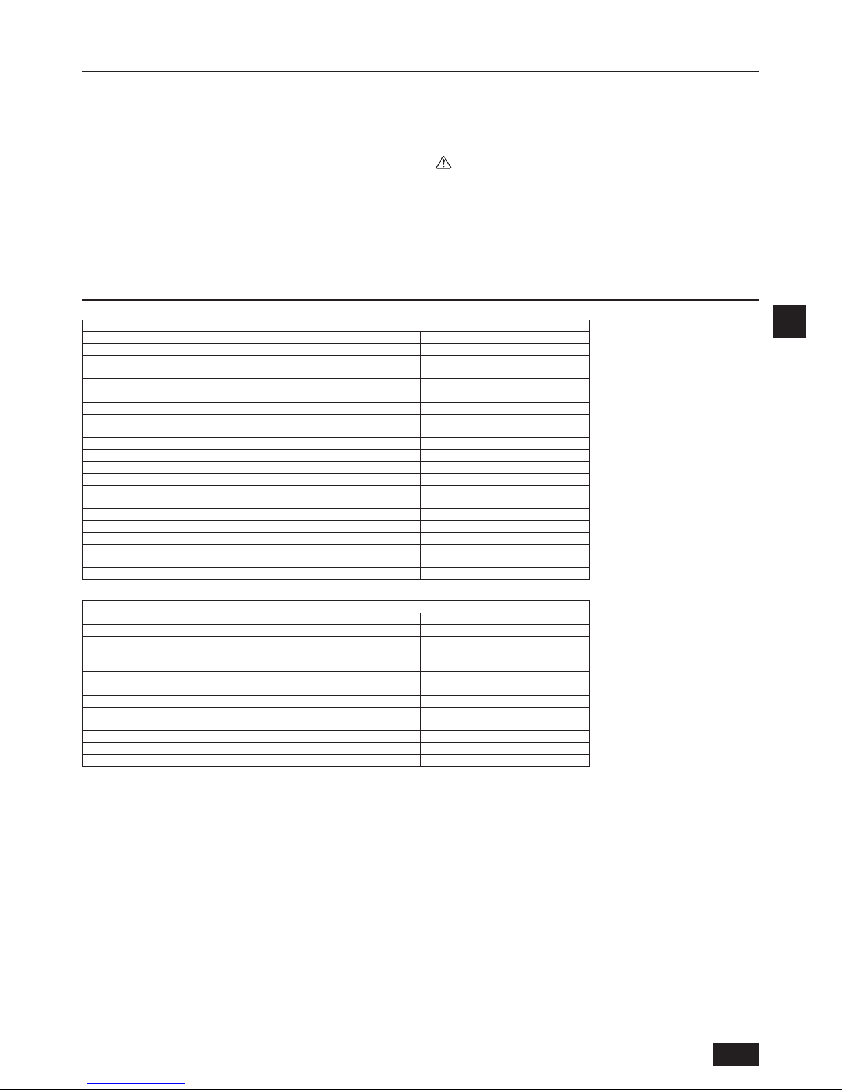
27
D
3. Kombination von Außeneinheiten
Nachfolgend sind Gerätekomponenten von PURY-P400 bis P900YSJM aufgelistet.
Außengerätmodell Gerätekomponentenmodell
PURY-P200YJM-A(-BS) - PURY-P250YJM-A(-BS) - PURY-P300YJM-A(-BS) - PURY-P350YJM-A(-BS) - PURY-P400YJM-A(-BS) - PURY-P400YSJM-A1(-BS) PURY-P200YJM-A(-BS) PURY-P200YJM-A(-BS)
PURY-P450YJM-A(-BS) - PURY-P450YSJM-A1(-BS) PURY-P250YJM-A(-BS) PURY-P200YJM-A(-BS)
PURY-P500YSJM-A(-BS) PURY-P250YJM-A(-BS) PURY-P250YJM-A(-BS)
PURY-P500YSJM-A1(-BS) PURY-P300YJM-A(-BS) PURY-P200YJM-A(-BS)
PURY-P550YSJM-A(-BS) PURY-P300YJM-A(-BS) PURY-P250YJM-A(-BS)
PURY-P600YSJM-A(-BS) PURY-P300YJM-A(-BS) PURY-P300YJM-A(-BS)
PURY-P600YSJM-A1(-BS) PURY-P350YJM-A(-BS) PURY-P250YJM-A(-BS)
PURY-P650YSJM-A(-BS) PURY-P350YJM-A(-BS) PURY-P300YJM-A(-BS)
PURY-P700YSJM-A(-BS) PURY-P400YJM-A(-BS) PURY-P300YJM-A(-BS)
PURY-P700YSJM-A1(-BS) PURY-P350YJM-A(-BS) PURY-P350YJM-A(-BS)
PURY-P750YSJM-A(-BS) PURY-P400YJM-A(-BS) PURY-P350YJM-A(-BS)
PURY-P800YSJM-A(-BS) PURY-P400YJM-A(-BS) PURY-P400YJM-A(-BS)
PURY-P800YSJM-A1(-BS) PURY-P450YJM-A(-BS) PURY-P350YJM-A(-BS)
PURY-P850YSJM-A(-BS) PURY-P450YJM-A(-BS) PURY-P400YJM-A(-BS)
PURY-P900YSJM-A(-BS) PURY-P450YJM-A(-BS) PURY-P450YJM-A(-BS)
Nachfolgend sind Gerätekomponenten von PURY-EP400 bis EP700YSJM aufgelistet.
Außengerätmodell Gerätekomponentenmodell
PURY-EP200YJM-A(-BS) - PURY-EP250YJM-A(-BS) - PURY-EP300YJM-A(-BS) - PURY-EP350YJM-A(-BS) - PURY-EP400YSJM-A(-BS) PURY-EP200YJM-A(-BS) PURY-EP200YJM-A(-BS)
PURY-EP450YSJM-A(-BS) PURY-EP250YJM-A(-BS) PURY-EP200YJM-A(-BS)
PURY-EP500YSJM-A(-BS) PURY-EP300YJM-A(-BS) PURY-EP200YJM-A(-BS)
PURY-EP500YSJM-A1(-BS) PURY-EP250YJM-A(-BS) PURY-EP250YJM-A(-BS)
PURY-EP550YSJM-A(-BS) PURY-EP300YJM-A(-BS) PURY-EP250YJM-A(-BS)
PURY-EP600YSJM-A(-BS) PURY-EP300YJM-A(-BS) PURY-EP300YJM-A(-BS)
PURY-EP600YSJM-A1(-BS) PURY-EP350YJM-A(-BS) PURY-EP250YJM-A(-BS)
PURY-EP650YSJM-A(-BS) PURY-EP350YJM-A(-BS) PURY-EP300YJM-A(-BS)
PURY-EP700YSJM-A(-BS) PURY-EP350YJM-A(-BS) PURY-EP350YJM-A(-BS)
2. Produktinformationen
Dieses Gerät verwendet Kältemittel des Typs R410A.
Rohrleitungen für Systeme, die R410A verwenden, können aufgrund des
konstruktionsbedingten höheren Drucks bei Verwendung von R410A von
denen für Systeme, die herkömmliche Kältemittel verwenden, abweichen.
Weitere Informationen sind im Datenbuch enthalten.
Einige zur Installation von Systemen, die andere Kältemitteltypen einsetzen,
verwendete Hilfsmittel und Geräte können nicht für Systeme verwendet
werden, die R410A einsetzen. Weitere Informationen sind im Datenbuch
enthalten.
•
•
•
Verwenden Sie keine vorhandenen Rohrleitungen, da diese Chlor enthalten,
das in herkömmlichen Kühlmaschinenölen und Kältemitteln Verwendung
fi ndet. Das Chlor beeinträchtigt das im neuen System verwendete
Kältemittelöl. Die vorhandenen Rohrleitungen dürfen auch deshalb nicht
verwendet werden, weil der konstruktionsbedingte Druck in Systemen,
die R410A verwenden, höher ist als in Systemen, die andere Kältemittel
verwenden, so dass die vorhandenen Rohrleitungen bersten könnten.
Vorsicht:
Lassen Sie R410A nicht in die Atmosphäre ab.
R410A ist ein vom Kyoto-Protokoll erfasstes fl uorhaltiges Treibhausgas
mit einem GWP (Global Warming Potential) von 1975.
•
•
•
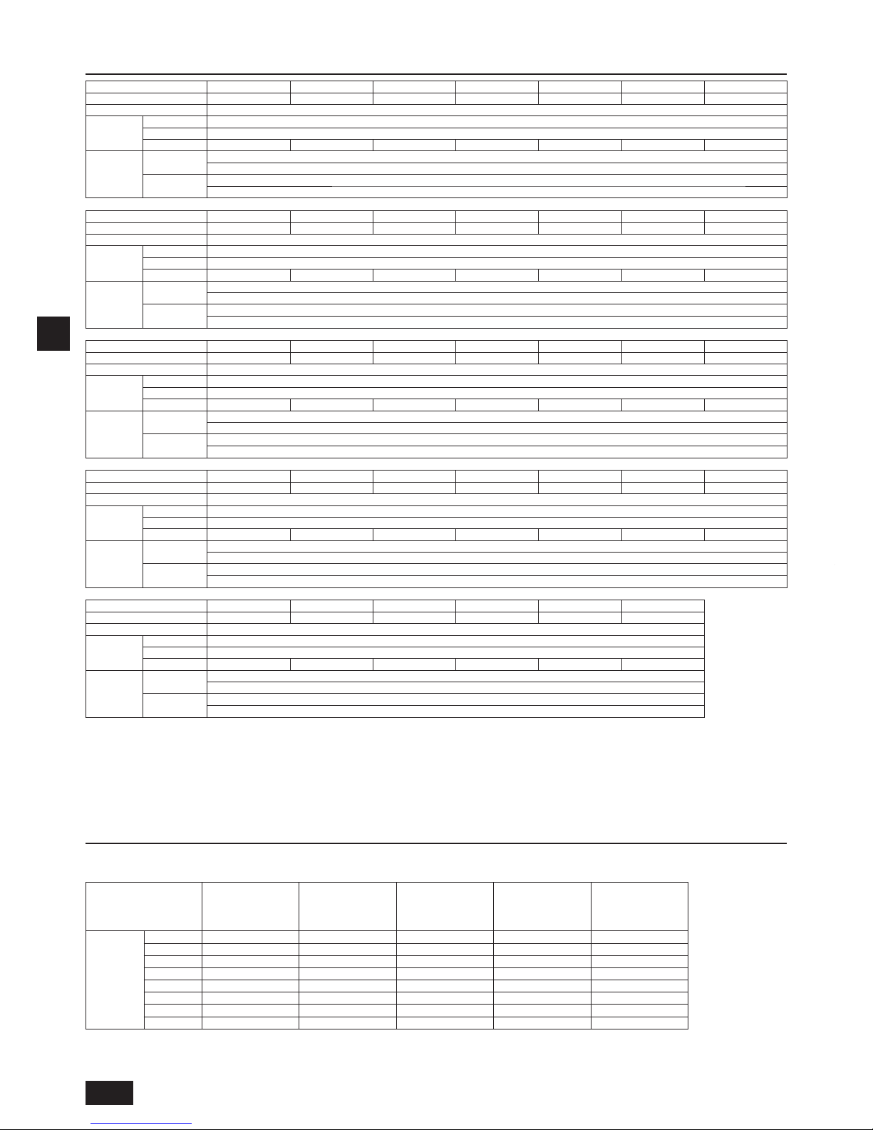
28
D
5. Bestätigung von Anschlussteilen
Dieses Gerät umfasst die folgenden Teile. Bitte prüfen.
Für Verwendungsmethoden siehe Punkt 10.2.
1 Verbindungsrohr
ID ø25,4, ID ø22,2
<Niederdruckseite>
<Hochdruckseite>
2 Verbindungsrohr
ID ø25,4, AD ø19,05
<Hochdruckseite>
3 Verbindungsrohr
ID ø25,4, ID ø28,58
<Niederdruckseite>
4 Anschlussbogen
ID ø19,05, AD ø19,05
<Hochdruckseite>
5 Anschlussbogen
ID ø28,58, AD ø28,58
<Niederdruckseite>
Modell P250YJM 1 Stck. ––––
P300YJM 1 Stck. ––––
P350YJM – 1 Stck. 1 Stck. 1 Stck. –
P400YJM 1 Stck. – 1 Stck. – –
P450YJM 1 Stck. – – – 1 Stck.
EP250YJM 1 Stck. 1 Stck. – 1 Stck. –
EP300YJM 1 Stck. 1 Stck. – 1 Stck. –
EP350YJM – 1 Stck. – 1 Stck. 1 Stck.
•
•
4. Technische Daten
Modell
PURY-P200YJM-A PURY-P250YJM-A PURY-P300YJM-A PURY-P350YJM-A PURY-P400YJM-A
PURY-P400YSJM-A1
PURY-P450YJM-A
Geräuschpegel (50/60 Hz)
56dB <A> 57dB <A> 59dB <A> 60dB <A> 61dB <A> 59dB <A> 62dB <A>
Externer statischer Druck
0 Pa *2
Innengeräte
Gesamtkapazität
50~150% *1
Modell
15~250
Menge
1~20 1~25 1~30 1~35 1~40 1~40 1~45
Betriebstemperatur
Standardtyp
Kühlbetrieb: – 5°CDB ~ 46°CDB
Heizbetrieb: – 20°CWB ~ 15,5°CWB
Frischluft-
ansaugung
Kühlbetrieb: 21°CDB ~ 43°CDB
Heizbetrieb: – 12,5°CWB ~ 20°CWB
Modell
PURY-P450YSJM-A1
PURY-P500YSJM-A
PURY-P500YSJM-A1
PURY-P550YSJM-A PURY-P600YSJM-A
PURY-P600YSJM-A1
PURY-P650YSJM-A
Geräuschpegel (50/60 Hz)
59,5dB <A> 60dB <A> 61dB <A> 61dB <A> 62dB <A> 62dB <A> 62,5dB <A>
Externer statischer Druck
0 Pa *2
Innengeräte
Gesamtkapazität
50~150% *1
Modell
15~250
Menge
1~45* 1~50* 1~50* 2~50* 2~50* 2~50* 2~50*
Betriebstemperatur
Standardtyp
Kühlbetrieb: – 5°CDB ~ 46°CDB
Heizbetrieb: – 20°CWB ~ 15,5°CWB
Frischluft-
ansaugung
Kühlbetrieb: 21°CDB ~ 43°CDB
Heizbetrieb: – 12,5°CWB ~ 20°CWB
Modell
PURY-P700YSJM-A
PURY-P700YSJM-A1
PURY-P750YSJM-A PURY-P800YSJM-A
PURY-P800YSJM-A1
PURY-P850YSJM-A
PURY-P900YSJM-A
Geräuschpegel (50/60 Hz)
63dB <A> 63dB <A> 63,5dB <A> 64dB <A> 64dB <A> 64.5dB <A> 65dB <A>
Externer statischer Druck
0 Pa *2
Innengeräte
Gesamtkapazität
50~150% *1
Modell
15~250
Menge
2~50* 2~50* 2~50* 2~50* 2~50* 2~50* 2~50*
Betriebstemperatur
Standardtyp
Kühlbetrieb: – 5°CDB ~ 46°CDB
Heizbetrieb: – 20°CWB ~ 15,5°CWB
Frischluft-
ansaugung
Kühlbetrieb: 21°CDB ~ 43°CDB
Heizbetrieb: – 12,5°CWB ~ 20°CWB
Modell
PURY-EP200YJM-A PURY-EP250YJM-A PURY-EP300YJM-A PURY-EP350YJM-A
PURY-EP400YSJM-A PURY-EP450YSJM-A PURY-EP500YSJM-A
Geräuschpegel (50/60 Hz)
57dB <A> 60dB <A> 60dB <A> 61dB <A> 60dB <A> 62dB <A> 62dB <A>
Externer statischer Druck
0 Pa *2
Innengeräte
Gesamtkapazität
50~150% *1
Modell
15~250
Menge
1~20 1~25 1~30 1~35 1~40 1~45 1~50*
Betriebstemperatur
Standardtyp
Kühlbetrieb: – 5°CDB ~ 46°CDB
Heizbetrieb: – 20°CWB ~ 15,5°CWB
Frischluft-
ansaugung
Kühlbetrieb: 21°CDB ~ 43°CDB
Heizbetrieb: – 12,5°CWB ~ 20°CWB
Modell
PURY-EP500YSJM-A1
PURY-EP550YSJM-A
PURY-EP600YSJM-A
PURY-EP600YSJM-A1
PURY-EP650YSJM-A PURY-EP700YSJM-A
Geräuschpegel (50/60 Hz)
63dB <A> 63dB <A> 63dB <A> 63,5dB <A> 63,5dB <A> 64dB <A>
Externer statischer Druck
0 Pa *2
Innengeräte
Gesamtkapazität
50~150% *1
Modell
15~250
Menge
1~50* 2~50* 2~50* 2~50* 2~50* 2~50*
Betriebstemperatur
Standardtyp
Kühlbetrieb: – 5°CDB ~ 46°CDB
Heizbetrieb: – 20°CWB ~ 15,5°CWB
Frischluft-
ansaugung
Kühlbetrieb: 21°CDB ~ 43°CDB
Heizbetrieb: – 12,5°CWB ~ 20°CWB
* Es können maximal 48 Zweigleitungen angeschlossen werden.
*1: Die Gesamtkapazität von gleichzeitig betriebenen Innengeräten beträgt 150% oder weniger.
*2: Zum Aktivieren von hohem statischen Druck für (E)P200, (E)P250, (E)P300, (E)P350, P400, und P450 stellen Sie den Dip-Schalter im Hauptfeld wie folgt ein:
SW3-9: ON, SW3-10 60 Pa-kompatibel: OFF, 30 Pa-kompatibel: ON

29
D
8.1. Installation
[Fig. 8.1.1] (S. 3)
<A> Ohne abnehmbaren Fuß <B> Mit abnehmbarem Fuß
A
Vor Ort zu beschaffender M10Ankerbolzen
B
Ecke liegt nicht auf
C
Halterung für Lochankerbolzen (an 3
Stellen verschrauben)
D
Abnehmbarer Fuß
Verschrauben Sie das Gerät sicher mit den Bolzen, um sein Abstürzen bei
starkem Wind oder Erdbeben zu verhindern.
Verwenden Sie Beton oder Winkeleisen als Gerätesockel.
Abhängig von den Installationsbedingungen können Schwingungen auf den
Installationsbereich übertragen oder Geräusche und Schwingungen von
Fußboden und Wänden erzeugt werden. Deshalb sollte eine ausreichende
Vibrationsdämpfung (Dämpfpolster, vibrationsgedämpfter Rahmen usw.)
gewährleistet sein.
Stellen Sie sicher, dass die Ecken fest aufl iegen. Wenn die Ecken nicht fest
aufl iegen, können die Stellfüße verbogen werden.
Achten Sie bei Verwendung von Dämpfpolstern darauf, dass die gesamte
Gerätebreite abgedeckt ist.
Der Ankerbolzen sollte nicht mehr als 30 mm hervorragen.
Lochankerbolzen sind mit diesem Produkt nicht kompatibel.
Lochankerbolzen können jedoch verwendet werden, wenn an den 4
Stellen (6 Stellen: P450, EP350) des Gerätebefestigungsteils Halterungen
angebracht werden.
•
•
•
•
•
•
•
[Fig. 8.1.2]
A
Schrauben
Der abnehmbare Fuß kann vor Ort entfernt werden.
Entfernen des abnehmbaren Fußes
Lösen Sie die drei Schrauben, um den abnehmbaren Fuß zu entfernen
(jeweils zwei (drei: P450, EP350) vorne und hinten).
Reparieren Sie die Aufl agefl äche, falls sie beim Entfernen des Fußes
beschädigt wird.
Achtung:
Vergewissern Sie sich, dass der Aufstellort eine dem Gewicht
entsprechende Tragkraft hat.
Eine unzureichende Tragkraft kann zum Herunterfallen des Geräts
führen und in Personenschäden resultieren.
Die Installationsarbeiten sind sturm- und erdbebensicher auszuführen.
Eine mangelhafte Installation kann zum Herunterfallen des Geräts
führen und in Personenschäden resultieren.
Achten Sie beim Anfertigen des Fundaments stets auf die Tragkraft des
Untergrunds, Wasserdrainage <während des Betriebs fl ießt Drainagewasser aus
dem Gerät> sowie Rohr- und Kabelverläufe.
Vorkehrungen beim Verlegen der Rohre und Kabel unterhalb des Geräts
(ohne abnehmbaren Fuß)
Achten Sie darauf, dass das Fundament die unten am Gerät befi ndlichen
Durchlässe nicht blockiert, wenn die Rohre und Kabel unterhalb des Geräts verlegt
werden. Achten Sie ebenfalls darauf, dass das Fundament mindestens 100 mm
hoch ist, so dass die Rohre unter dem Gerät durchgeführt werden können.
•
•
•
•
8. Installieren des Geräts
6. Um das Gerät erforderlicher Freiraum
1 Bei einer Einzelinstallation
Gewährleisten Sie einen ausreichenden Freiraum um das Gerät wie im Bild
auf Seite 2 dargestellt.
[Fig. 6.0.1] (S. 2)
<A> Draufsicht <B> Seitenansicht
<C> Bei einem geringen Abstand zu einem Hindernis
A
Front
B
Gerätehöhe
C
Rückseite
D
Luftauslassführung (vor Ort zu beschaffen)
(1) Bei einem Abstand von 300 mm oder mehr zwischen der Rückseite
und der Wand
(2) Bei einem Abstand von 100 mm oder mehr zwischen der Rückseite
und der Wand
(3) Bei einer größeren Wandhöhe (H) an der Front, Rückseite oder Seite
als der maximal zulässigen Wandhöhe
Wenn die Höhe der Wände an der Front, Rückseite oder den Seiten <H> die
hier defi nierte maximal zulässige Wandhöhe überschreitet, addieren Sie die
Höhe, die die maximal zulässige Wandhöhe überschreitet <h> zu den mit
einem Sternchen gekennzeichneten Werten.
Wenn das Gerät nicht mit Abstand zur Wand aufgestellt werden kann,
ändern Sie die Richtung der Lüftungsöffnung so, dass der Luftstrom gegen
die Wand gerichtet ist, um einen kurzen Luftkreislauf zu vermeiden.
•
•
•
<Maximal zulässige Wandhöhe>
Front: Bis zur Gerätehöhe
Rückseite: Bis zu 500 mm von der Geräteunterkante
Seite: Bis zur Gerätehöhe
(4) Wenn am oberen Teil des Geräts Hindernisse vorhanden sind
2 Bei einer kollektiven Installation
[Fig. 6.0.2] (S. 2)
A
Front
B
Muss offen sein
C
Wandhöhe (H)
Halten Sie beim Installieren mehrerer Geräte nebeneinander ausreichend
Freiraum für die Luftzirkulation und einen Durchgang zwischen den
Gerätegruppen ein, wie in den Bildern auf Seite 2 dargestellt.
Zumindest zwei Seiten müssen offen bleiben.
Addieren Sie wie bei der Einzelinstallation die Höhe, die die maximal
zulässige Höhe überschreitet <h>, zu den mit einem Sternchen
gekennzeichneten Werten.
Wenn sich eine Wand sowohl vor als auch hinter dem Gerät befi ndet.
Installieren Sie bis zu sechs Geräte (drei Geräte: P450, EP350) in Folge in
seitlicher Richtung und halten Sie einen Abstand von mindestens 1000 mm
als Platz für den Einlass/Durchgang für jedes der sechs Geräte (drei Geräte:
P450, EP350).
•
•
•
•
[Fig. 7.0.1] (S. 3)
Verwenden Sie Tragseile mit einer für das Gewicht des Geräts
ausreichenden Tragkraft.
Verwenden Sie beim Transport des Geräts eine 4-Punkt-Aufhängung und
setzen Sie das Gerät keinen Stößen aus (verwenden Sie keine 2-Punkt-
Aufhängung).
Legen Sie an den Stellen des Geräts, die mit den Seilen in Kontakt kommen,
Schutzpolster auf, um das Gerät gegen Kratzschäden zu schützen.
Halten Sie bei der Verseilung einen Winkel von maximal 40° ein.
Verwenden Sie 2 Seile, die jeweils länger als 8 Meter sind.
•
•
•
•
•
Bringen Sie an den Ecken des Produkts Schutzpolster an, um es gegen von
den Seilen verursachte Kratzschäden oder Beulen zu schützen.
Vorsicht:
Gehen Sie beim Tragen/Transport des Produkts sehr sorgfältig vor.
- Stützen Sie das Außengerät bei seiner Installation an den angegebenen
Stellen der Gerätebasis ab. Stabilisieren Sie es erforderlichenfalls, um ein
seitliches Verrutschen zu verhindern und stützen Sie es an 4 Stellen ab.
Falls das Gerät unter Verwendung einer 3-Punkt-Aufhängung installiert oder
angehoben wird, könnte es instabil werden und herunterfallen.
•
7. Hebemethode
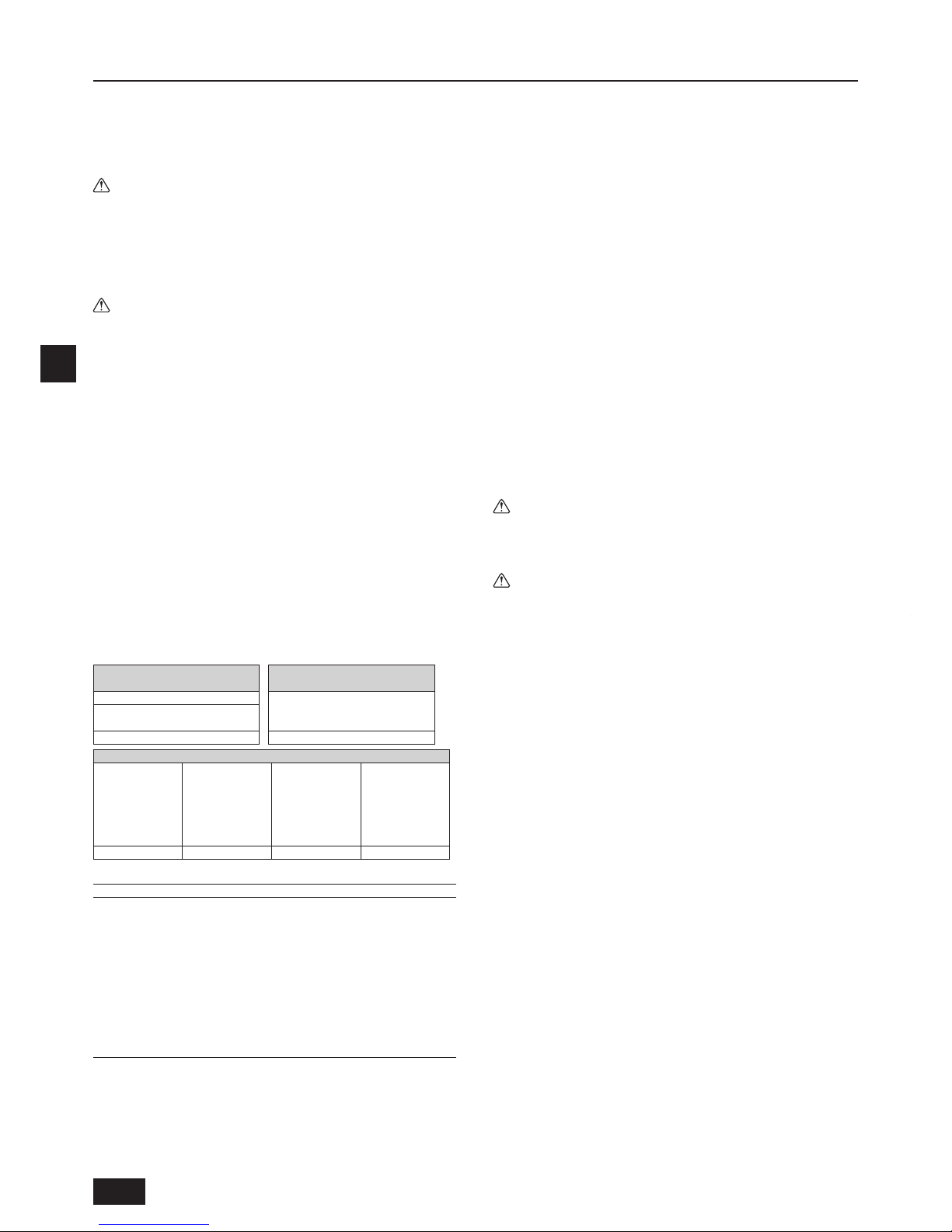
30
D
9. Installieren der Kältemittelleitungen
Die Leitung wird an einen Verteiler angeschlossen, an dem die vom Außengerät
kommende Leitung zu jedem der Innengeräte verzweigt wird.
Die Rohranschlüsse werden wie folgt hergestellt: Bördelverbindung für die
Innengeräte, Niederdruck- und Hochdruckrohrleitungen, hartgelötete Verbindung
für die Außengeräte. Beachten Sie, dass die abgezweigten Abschnitte
hartgelötet sind.
Achtung:
Gehen Sie bei der Verwendung von Feuer und Flammen stets extrem
sorgfältig vor, um das Austreten des Kältegases zu verhindern. Wenn das
Kältegas mit einer Flamme in Kontakt kommt, wie zum Beispiel einem
Gasherd, zersetzt es sich und setzt Giftgas frei, das zu einer Gasvergiftung
führen kann. Führen Sie Schweißarbeiten nie in unbelüfteten Räumen
durch. Führen Sie nach dem Installieren der Kältemittelrohrleitungen stets
eine Gasleckageinspektion durch.
Vorsicht:
Lassen Sie R410A nicht in die Atmosphäre ab.
R410A ist ein vom Kyoto-Protokoll erfasstes fl uorhaltiges Treibhausgas
mit einem GWP (Global Warming Potential) von 1975.
9.1. Vorsichtshinweise
Dieses Gerät verwendet Kältemittel des Typs R410A. Befolgen Sie bei der
Auswahl der Rohrleitungen die örtlich geltenden Vorschriften für Material und
Rohrstärke. (Siehe Tabelle, unten.)
1 Verwenden Sie für die Kältemittelrohrleitungen die folgenden Materialien:
Material: Verwenden Sie aus deoxidiertem Phosphorkupfer
gefertigte nahtlose Kupferlegierungsrohre. Stellen Sie sicher,
dass die Innen- und Außenfl ächen der Rohre sauber und frei von
gefährlichen Rückständen wie Schwefel, Oxid, Staub, Spänen, Öl
und Feuchtigkeit sind (Kontaminierung).
Größe: Abschnitt 9.2. enthält detaillierte Angaben zum
Kältemittelrohrleitungssystem.
2 Handelsübliche Rohre enthalten häufi g Staub oder anderes Material. Blasen
Sie sie stets mit einem trockenen Schutzgas sauber.
3 Achten Sie während der Installation sorgfältig darauf, dass kein Staub,
Wasser oder sonstige Verunreinigungen in die Rohre eindringen.
4 Begrenzen Sie die Anzahl der Biegungen soweit wie möglich und legen Sie
die Biegeradien möglichst groß aus.
5 Verwenden Sie für Abzweigungen und Sammler im Innen- und Außenbereich
stets die folgenden Zwillingsrohr- und Sammelrohrsätze (getrennt erhältlich).
Innengerät-
Zwillingsrohrsatzmodell
Innengerät-
Anschlussrohrsatzmodell
Leitungsabzweigung
Innengerätemodell (insgesamt)
P100 ~ P250
Stromab gelegenes Gerätemodell
Weniger als insgesamt 80
CMY-Y102S-G2 CMY-R160-J1
Außengerät-Zwillingsanschlusssatz
Außengerätemodell
(insgesamt)
P500 ~ P650YSJM-A
P400 ~ P600YSJM-A1
EP400 ~ EP600YSJM-A
EP500YSJM-A1
Außengerätemodell
(insgesamt)
P700 ~ P800YSJM-A
P700YSJM-A1
Außengerätemodell
(insgesamt)
P800YSJM-A1
EP650, EP700YSJM-A
EP600YSJM-A1
Außengerätemodell
(insgesamt)
P850, P900YSJM-A
CMY-R100VBK CMY-R200VBK
CMY-R100XLVBK CMY-R200XLVBK
Kupferrohrgröße und radiale Stärke für R410A CITY MULTI.
Größe (mm) Größe (Zoll) Radiale Stärke (mm) Rohrtyp
ø6,35 ø1/4" 0,8 Typ O
ø9,52 ø3/8" 0,8 Typ O
ø12,7 ø1/2" 0,8 Typ O
ø15,88 ø5/8" 1,0 Typ O
*ø19,05 ø3/4" 1,2 Typ O
*ø19,05 ø3/4" 1,0 Typ 1/2H oder H
ø22,2 ø7/8" 1,0 Typ 1/2H oder H
ø25,4 ø1" 1,0 Typ 1/2H oder H
ø28,58 ø1-1/8" 1,0 Typ 1/2H oder H
ø31,75 ø1-1/4" 1,1 Typ 1/2H oder H
ø34,93 ø1-3/8" 1,2 Typ 1/2H oder H
ø41,28 ø1-5/8" 1,4 Typ 1/2H oder H
* Für die Rohrgröße ø19,05 (3/4 Zoll) können an R410A-Klimageräten beide
Rohrtypen verwendet werden.
6 Verwenden Sie ein Fitting, falls eine angegebene Kältemittelleitung einen
anderen Durchmesser als eine Zweigleitung hat.
7 Beachten Sie stets die Grenzwerte für die Kältemittelleitung (wie zum
Beispiel die Nennlänge, den Höhenunterschied und den Rohrdurchmesser),
um einen Geräteausfall oder einen Heiz-/Kühlleistungsverlust zu verhindern.
•
•
•
•
8 Die Notausschaltung des Geräts spricht sowohl bei zuwenig als auch
zuviel Kältemittel an. Füllen Sie das System mit der angemessenen
Menge Kältemittel. Lesen Sie bei Wartungsarbeiten stets die Notizen
zur Rohrlänge und zur Kältemittelnachfüllmenge an beiden Stellen - der
Berechnungstabelle für die Kältemittelmenge an der Rückseite der
Wartungsabdeckung und den Abschnitt bezüglich der Kältemittelnachfüllung
auf den Etiketten für alle Innengeräte. (Abschnitt 9.2. enthält detaillierte
Angaben zum Kältemittelrohrleitungssystem.)
9 Füllen Sie das System nur mit fl üssigem Kältemittel.
0 Verwenden Sie Kältemittel nie zum Entlüften des Systems. Verwenden
Sie zum Entlüften stets eine Vakuumpumpe.
a Isolieren Sie die Rohrleitungen stets ordnungsgemäß. Eine unzureichende
Isolierung resultiert in einem Verlust der Heiz-/Kühlleistung, Wasserbildung
durch Kondensation und ähnlichen Problemen. (Die Thermoisolierung der
Kältemittelleitungen ist im Abschnitt 10.4 beschrieben.)
b
Vergewissern Sie sich beim Anschließen der Kältemittelleitungen, dass das
Ventil am Außengerät vollständig geschlossen ist (die werksseitige Einstellung)
und betätigen Sie es nicht, bis die Kältemittelleitungen für die Außengeräte,
Innengeräte und BC-Steuerung angeschlossen sind, ein Kältemittelleckagetest
durchgeführt wurde und die Systementlüftung abgeschlossen ist.
c Verwenden Sie zum Hartlöten nur oxidfreies Material für Rohrleitungen.
Andernfalls kann der Kompressor beschädigt werden. Führen Sie zum
Hartlöten unbedingt eine Stickstoffspülung durch.
Verwenden Sie keine im Handel erhältlichen antioxygenen Mittel,
da diese in der Korrosion der Rohre und einem Güteverlust des
Kältemittelöls resultieren können.
Bitte wenden Sie sich bezüglich weiterer Einzelheiten an Mitsubishi Electric.
(Abschnitt 10.2. enthält Details zum Rohrleitungsanschluss und zur
Verwendung des Ventils.)
d Führen Sie den Rohrleitungsanschluss für das Außengerät nie bei
Regen aus.
Achtung:
Füllen Sie das Gerät bei der Installation und beim Transport mit keinem
anderen als dem am Gerät angegebenen Kältemittel.
-
Das Beimischen von einem anderen Kältemittel, Luft usw. kann eine
Funktionsstörung des Kältemittelkreislaufs und schwere Schäden verursachen.
Vorsicht:
Verwenden Sie eine Vakuumpumpe mit Rückschlagventil.
- Wenn die Vakuumpumpe nicht mit einem Rückschlagventil ausgestattet ist,
könnte in der Pumpe befi ndliches Öl in den Kältemittelkreislauf gelangen
und einen Güteverlust des Kältemittelöls verursachen.
Verwenden Sie keine der folgenden Hilfsmittel, die in Verbindung mit
herkömmlichen Kältemitteln verwendet werden.
(Messverteiler, Füllschlauch, Gasleckagedetektor,
Rückschlagventil, Kältemittelfüllständer, Unterdruckmesser,
Kältemittelrückgewinnungsausrüstung)
- Das Mischen von herkömmlichem Kältemittel und Kältemittelöl kann einen
Güteverlust des Kältemittelöls verursachen.
-
Das Beimischen von Wasser verursacht einen Güteverlust des Kältemittelöls.
- R410A-Kältemittel ist vollkommen chlorfrei. Für herkömmliche Kältemittel
verwendete Gasleckagesensoren sprechen deshalb nicht an.
Behandeln Sie die für R410A verwendeten Hilfsmittel sorgfältiger als üblich.
- Falls Staub, Schmutz oder Wasser in den Kältemittelkreislauf eindringt,
kann dies einen Güteverlust des Kältemittelöls verursachen.
Verwenden Sie niemals bereits vorhandene Kältemittelrohre.
-
Der hohe Chlorgehalt von herkömmlichem Kältemittel und Kältemittelöl in bereits
vorhandenen Rohren verursacht einen Güteverlust des neuen Kältemittels.
Lagern Sie die bei der Installation zu verwendenden Rohre in einem
Innenraum und halten Sie beide Rohrenden bis kurz vor dem Hartlöten
verschlossen.
- Falls Staub, Schmutz oder Wasser in den Kältemittelkreislauf eindringt,
resultiert dies in einem Güteverlust des Kältemittels und einem möglichen
Ausfall des Kompressors.
Verwenden Sie keinen Füllzylinder.
- Die Verwendung eines Füllzylinders kann einen Güteverlust des
Kältemittels verursachen.
Verwenden Sie keine Spezialreiniger zum Reinigen der Rohrleitungen.
•
•
•
•
•
•
•
 Loading...