

Mitsubishi Electric City Multi PUMY-P36NHMU, City Multi PUMY-P36NHMU-BS Datasheet
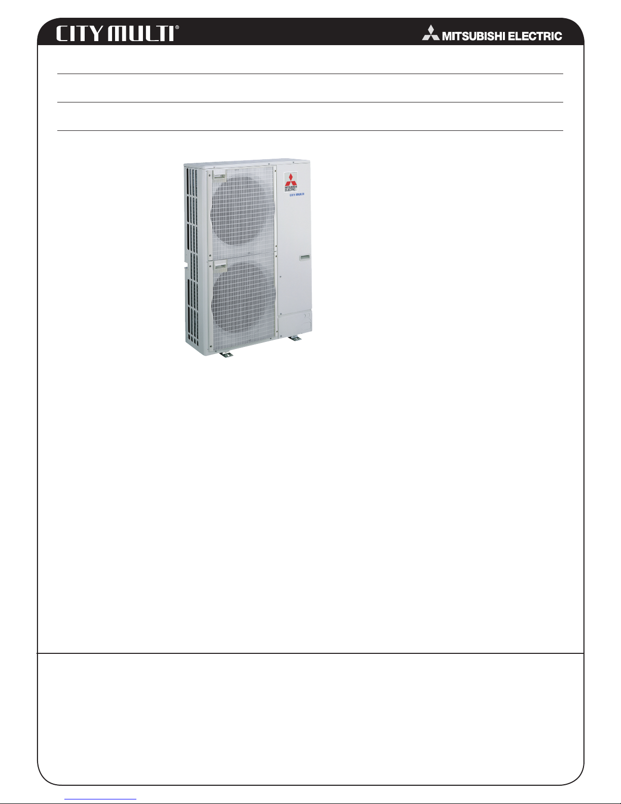
Model: PUMY-P36NHMU (-BS)
Job Name:
Drawing Reference: Schedule No.
System No.:
OUTDOOR VRF
SYSTEM FEATURES
tinu roodtuo esahp-elgniS •
with variable refrigerant
ow (VRF)
technology
• Inverter-driven (variable
speed) compressor
• Total refrigerant piping
length of 394' (120 m)
• Uses CITY MULTI indoor
units and Controls Network
OUTDOOR VRF SYSTEM
SPECIFICATIONS
Capacity
Cooling……………………………………………..36,000 Btu/h
Heating……………………………………………..40,000 Btu/h
Power
Power Source……………….........208 / 230V, 1-phase, 60Hz
Power Input
Cooling………………………………………………3.22 kW
Heating………………………………………………2.93 kW
Current
Cooling (208 / 230)........................................14.2 / 15.7 A
Heating (208 / 230) ...................................…12.9 / 14.2 A
Minimum Circuit Ampacity (MCA) (208 / 230)….……..…26 A
Breaker Size for Wiring ........................................….......30 A
External Finish………Pre-coated Galvanized-steel Sheets
Munsell No. 3Y 7.8 / 1.1
External Dimensions
Inches………………..53-3/16 h x 37-7/16 w x 13 (+1-3/16) d
mm……………………………..1,350 h x 950 w x 330 (+30) d
Net Weight………………………………….287 lbs. / 130 kg
Fan
Type x Quantity...………..............................Propeller Fan x 2
Airflow Rate……………………………………...……3,530 cfm
Motor Output……...…..………………………0.086 + 0.086 kW
Compressor
Type………………...................………….Inverter-driven Scroll
Motor Output………..…………………………………….2.2 kW
Lubricant………………..…...………………………….FV50S
Refrigerant……………..…...…………………………..R410A
Protection Devices
High Pressure Protection………………High Pressure Switch
Compressor…………Discharge Thermo / Overcurrent Detection
Fan…...…………………………..Overheat / Voltage Protection
Piping Diameter
Liquid (High Pressure)………..……………3/8" / 9.52 mm Flare
Gas (Low Pressure)………………………5/8" / 15.88 mm Flare
Indoor Unit
Total Capacity…..…….50% –130% of Outdoor Unit Capacity
Model / Quantity…………………..…………..….P06-P36 / 1 ~ 6
Sound Level (Cooling / Heating)………….49 / 51 dB(A)
Operating Temperature Range
Cooling (Outdoor)……………….23°F ~ 115°F (-5° ~ +46°C) DB*
Heating (Outdoor)…………….0°F ~ +60°F (-18° ~ +15°C) WB
Anti-corrosion Protection
Blue Fin Treatment applied to condenser coil protects coil
from airborne contaminants.
Seacoast Protection
External Panel Base: Steel sheets with aluminum-zinc-
•
magnesium coating on external and internal surfaces
•
External Panel (Top, Front, Back): Galvanized steel sheets
with acrylic- and polyester-resin coating on external and
internal surfaces
•
Fan Motor Support: Galvanized-steel sheets with epoxy resin coating applied to external surface
•
Separator and Valve Bed: Galvanized-steel sheets with
epoxy-resin coating
Options
□ Branch Joint (T-Branch)…………………..…....CMY-Y62-G-E
□ Header - Four-Branch…………………………….CMY-Y64-G-E
□ Header - Eight-Branch……………………………..CMY-Y68-G-E
□ Drain Pan………………………………….….….PAC-SG64DP-E
□ Drain Socket………………………………….….PAC-SG61DS-E
Notes:
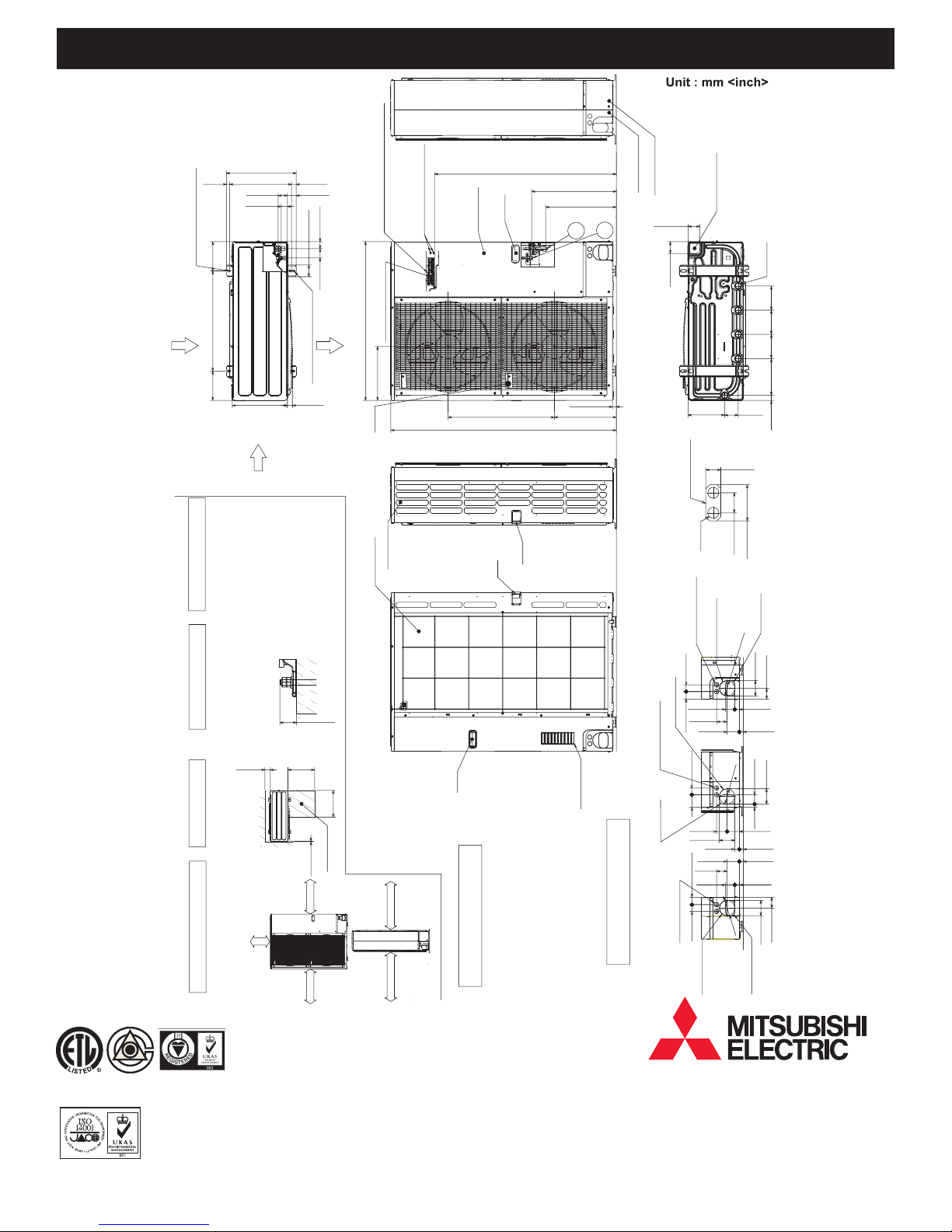
Model: PUMY-P36NHMU (-BS) – DIMENSIONS
19<3/4>
2-U Shaped notched hole
(Foundation Bolt M10<W3/8>)
175
<6-7/8>
Rear Air Intake
600<23-5/8>
175
<6-7/8>
417<16-13/32>
56<2-7/32>
37<1-15/32>
330<13>
Side Air Intake
4 PIPING-WIRING DIRECTIONS
Piping and wiring connections
can be made using one of four
locations on the unit: front, right,
back, and bottom.
28<1-3/32> 370<14-9/16>
53<2-3/32>
Left …… For the power supply
70<2-3/4>
2-12 o36 Oval hole
Terminal block
56<2-7/32> 42<1-21/32>
Air Discharge
950<37-13/32>
(Foundation Bolt M10<W3/8>)
30<1-3/16>
Center … For the transmission line
Right…… For concentration control
( )
Ground for the transmission line
Ground for concentration control
Ground for the power supply
("GR"marking position)
322<12-11/16>
Handle
Side Air Intake
Rear Air Intake
Handle
Service panel
635<25>371<14-19/32>
1350<53-5/32>
Handle
Handle
1088<42-27/32>
1
w1 507<19-31/32>
w1 423<16-21/32>
2
23<29/32>
Front piping cover
Rear piping cover
71<2-13/16>
When installing the conduit,
set the attachment to the
Bottom piping hole
(Knockout)
71<2-13/16>
1/2 Conduit attachment
inside of each panel.
2-ø22<7/8>
Conduit hole
(2-n27<1-1/16>Knockout)
Rear trunking hole
(Knockout)
219<8-5/8>
40<1-9/16>
n92
<3-5/8>
Drain hole
5-n33<1-5/16>
145
145
145
220
81<3-3/16>
31<1-7/32>
74<2-19/32>
Back piping hole
(Knockout)
<5-23/32>
<5-23/32>
<5-23/32>
<8-21/32>
30<1-3/16>
mm<inch>
Certicate Number FM33568
Certicate Number EC97J1227
FOUNDATION
Please rmly secure the unit
using 4 foundation (M10<W3/8>)
2 SERVICE SPACE 3 FOUNDATION BOLTS
Space needed for service
access is shown in the
1 CLEARANCE SPACE
The diagram below shows a
basic example.
Mitsubishi Electric Air Conditioning & Refrigeration Systems Works acquired environmental
management system standard ISO 14001 certication.
The ISO 14000 series is a set of standards applying to environmental protection set by the
International Standard Organization (ISO).
<Foundation bolt height>
bolts.(Bolts and washers must
be purchased separately.)
<5-29/32>
Min.150mm
diagram below.
FREE
See the installation manuals for details.
Mitsubishi Electric Air Conditioning & Refrigeration Systems Works acquired ISO
9001 certication under Series 9000 of the International Standard Organization (ISO)
based on a review of quality warranties for the production of refrigeration and air
conditioning equipment.
ISO Authorization System
The ISO 9000 series is a plant authorization system relating to quality warranties as
stipulated by the ISO. ISO 9001 certies quality warranties based on the "design,
development, production, installation and auxiliary services" for products built at
an authorized plant.
<19-11/16>
Min.500mm
Min.500mm
Service space
Min.10mm<3/8>
Min.10mm<3/8>
Min.10mm<3/8>
30mm<1-3/16>
Max.
<19-11/16>
Min.150mm<5-29/32>
Min.1000mm<39-3/8>
Handle
Ø
Ø
Example of Notes
1 ……Refrigerant GAS pipe connction (FLARE) 15.88 (5/8 inch)
2 ……Refrigerant LIQUID pipe connection (FLARE) 9.52 (3/8 inch)
w1…..Indication of STOP VALVE connection location.
92<3-5/8>
65<2-9/16>
Right trunking hole
(Knockout)
45<1-25/32> 40<1-9/16>
Conduit hole
(2-n27<1-1/16>Knockout)
40<1-9/16>
63<2-1/2>
n92
27<1-1/16> 55<2-3/16>
23<29/32> 73<2-7/8>
/8>
<3-5
92<3-5/8>
Air intake
75
Right piping hole
(Knockout)
Conduit hole
<2-31/32>
45<1-25/32>40<1-9/16>
(2-n27<1-1/16>Knockout)
92<3-5/8>
73<2-7/8>
<2-1/2>
63
55<2-3/16>
19<3/4> 55<2-3/16>
73<2-7/8> 63<2-1/2>
23<29/32> 27<1-1/16>
23<29/32>
27<1-1/16>
/8>
<3-5
n92
65<2-9/16>
92<3-5/8>
Piping Knockout Hole Details
Front piping hole
Front trunking hole
(Knockout)
(Knockout)
Mitsubishi Electric Sales Canada Inc.
www.MitsubishiElectric.ca
Specifications are subject to change without notice.
PUMY-P36NHMU(-BS)_200802b © MITSUBISHI ELECTRIC
 Loading...