

Mitsubishi Electric City Multi PUMY-P125YMA, City Multi PUMY-125YMA Installation Manual

Air-Conditioners For Building Application
OUTDOOR UNIT
PUMY-P125YMA
PUMY-125YMA
INSTALLATION MANUAL
For safe and correct use, please read this installation manual thoroughly before installing the air-conditioner unit.
E°XEIPI¢IO O¢H°IøN E°KATA™TA™H™
°И· ·ЫК¿ПВИ· О·И ЫˆЫЩ‹ ¯Ъ‹ЫЛ, ·Ъ·О·ПВ›ЫЩВ ‰И·‚¿ЫВЩВ ЪФЫВ¯ЩИО¿ ·˘Щfi ЩФ ВБ¯ВИЪ›‰ИФ ВБО·Щ¿ЫЩ·ЫЛ˜ ЪИУ ·Ъ¯›ЫВЩВ ЩЛУ
ВБО·Щ¿ЫЩ·ЫЛ ЩЛ˜ МФУ¿‰·˜ ОПИМ·ЩИЫМФ‡.
РУКОВОДСТВО ПО УСТАНОВКЕ
Для осторожного и правильного использования прибора необходимо тщательно ознакомиться с данным руководством по
установке до выполнения установки кондиционера.
MONTAJ ELK‹TABI
Emniyetli ve do¤ru biçimde nas›l kullan›laca¤›n› ö¤renmek için lütfen klima cihaz›n› monte etmeden önce bu elkitab›n› dikkatle okuyunuz.
2
4
[Fig. 4.0.1]
[Fig. 5.0.1]
5
<B>
(2)
<A>
(1)
<A>
(3)
(4)
<B>
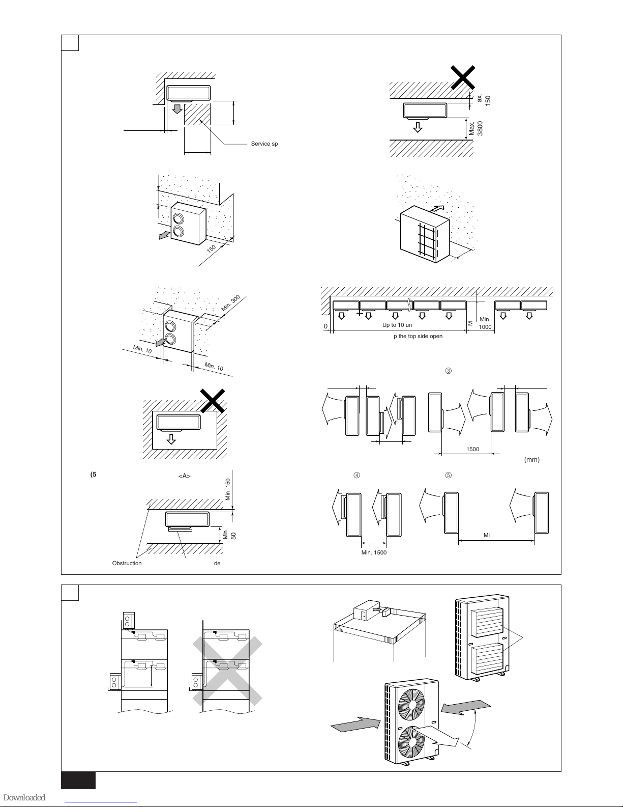
Service space
(mm)
Min.
500
Min. 150
Min. 10
Min. 10
Min. 300
;;;
;
;;;
;
<A>
(5)
Air outlet guideObstruction
Min. 150
Min.
500
<A>
<B>
(6)
<A>
(7)
Min.
150
Min.
1000
Up to 10 units
Keep the top side open
Min. 300
Min. 10
(mm)
M
in. 500
1
2
Min. 300
Min. 500
Min. 300
Min. 1500
3
45
(mm)
Min. 1500
Min. 3800
(mm)
A
1
90°
Air outlet
guide
Strong wind
2
3
Min. 10
Min.
500
Min.
500
Max.
150
Max.
3800
3
[Fig. 6.2.1]
6
[Fig. 6.1.1]
6.1
6.2
[Fig. 6.1.2]
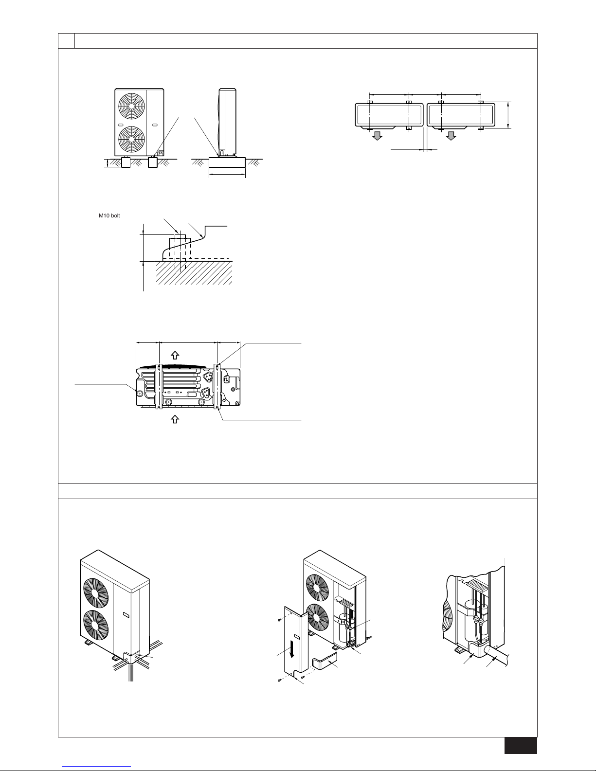
Make the
embedding
deep
Make wide
A M10 bolt
M10 bolt (Fasten with bolt)
Installation base
Max. 25 mm
Length of foundation bolts
600 Min. 430
385
Min. 10
(mm)
600
Slot (2-12 × 36)
(Foundation bolts:
M10)
Air outlet
Rear air inlet
U-shaped cut-out (×2)
(Foundation bolts: M10)
Drainage hole
(3-ø33)
Viewed from bottom
Piping cover
Front piping
(knockout)
Lower piping
Right piping
(knockout)
Rear piping
Stop valve
Bending radius
R 100 - 150 mm
Extraction direction
for service panel
Service panel
Piping cover
Piping cover
Racking
210 600 210
4
7
7.2
D
C
C
B
E
F
G
H
I
J
A
LO
HI
B
A
K
J
L
H
M
C
D
E
F
G
I
LO HI
[Fig. 8.3.1]
[Fig. 8.3.3]
[Fig. 8.3.2]
8.3
8.2
8
[Fig. 7.2.1]
B
A
H
B C
L
r
D
e
ahb c d
C
C
CCC
B
A
a
b
c d
C
D
CCC
CC
e f
H
h
L
r
[Fig. 8.2.2]
[Fig. 8.2.1]
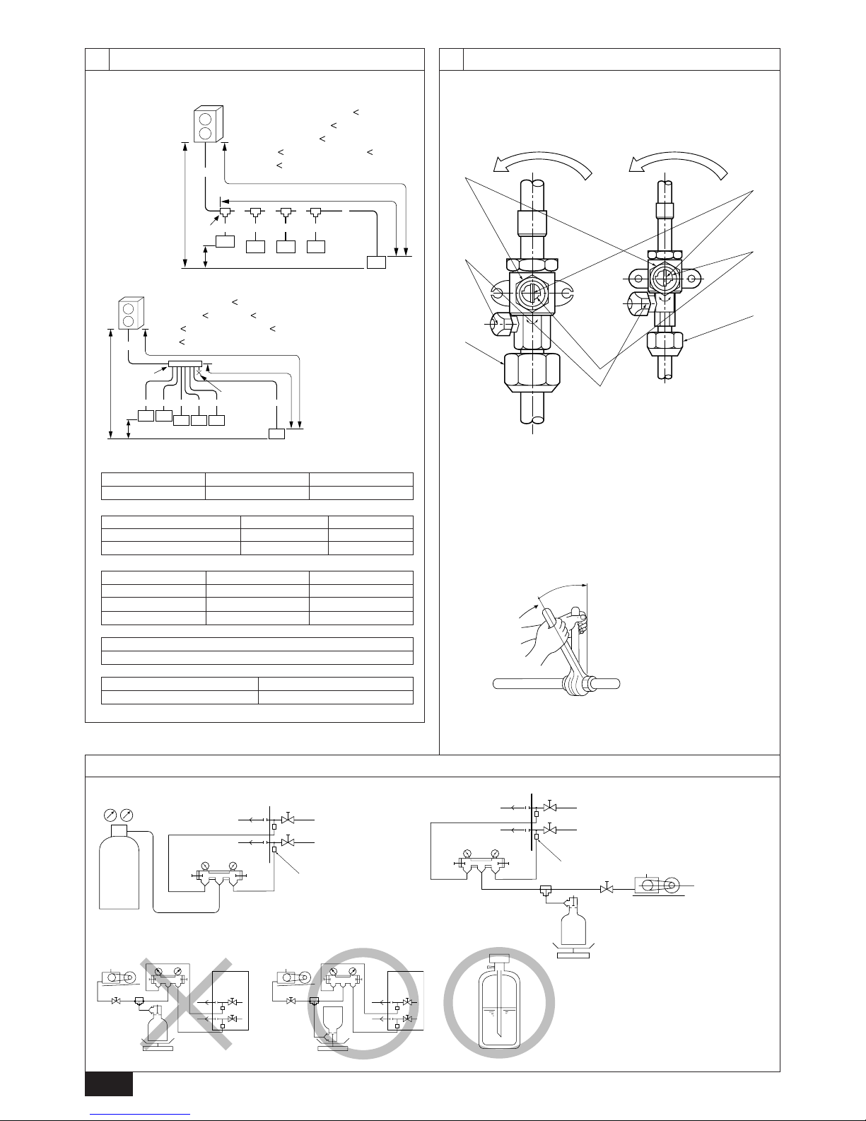
A : Outdoor Unit
B : First Branch
C : Indoor unit
D : Cap
A : Valve stem
B : Stopper pin
E : Open (Operate slowly)
F : Cap, copper packing
G : Service port
H : Flare nut
A : Nitrogen gas
B : To indoor unit
C : System analyzer
D : Lo Knob
E : Hi Knob
F : Stop valve
G : Liquid pipe
H : Gas pipe
I : Outdoor unit
J : Service port
A (mm)
Å Liquid pipe ı Gas pipe
PUMY-(P)125 ø9.52 ø19.05
B, C, D (mm)
Ç Total capacity of indoor units Å Liquid pipe ı Gas pipe
~ 80 ø9.52 ø15.88
81 ~ ø9.52 ø19.05
a, b, c, d, e, f (mm)
Î Model number Å Liquid pipe ı Gas pipe
20,25,32,40 ø6.35 ø12.7
50,63,80 ø9.52 ø15.88
100,125 ø9.52 ø19.05
‰ Branch Kit Model
CMY-Y62-C-E
Ï 4-Branching Header Ì 8-Branching Header
CMY-Y64-C CMY-Y68
<B> Stop valve (liquid pipe)
A : System analyzer
B : Lo Knob
C : Hi Knob
D : Ball valve
E : Liquid pipe
F : Gas pipe
G : Service port
H : Three-way joint
I : Valve
J : Valve
K : Cylinder
L : Scale
M : Vacuum pump
A+B+C+D+a+b+c+d+e
=
100m
L = A+B+C+D+e
=
70m
R= B+C+D+e
=
30m
H
=
30m (Outdoor lower H = 20m)
h
=
12m
A+a+b+c+d+e+f
=
100m
L = A+e
=
70m, R= f = 30m
H
=
30m (Outdoor lower H = 20m)
h
=
12m
SO
SO
F
EE
EE
A
B
H
G
H
<A> Stop valve (gas pipe)
(This figure shows the handle when it is fully open.)
To open
(turn
slowly)
To open
(turn
slowly)
5
9.4
9
8.4
[Fig. 8.4.4]
[Fig. 8.4.3]
[Fig. 8.4.2]
C
A
B
D
E
[Fig. 8.4.1]
[Fig. 9.4.1]
D D
C
A
D D
A
B
3 N~380 - 415 V
~/N 220 - 240 V
[Fig. 9.2.1]
[Fig. 9.3.2]
B
A
D
C
E
E
E
D
A
B
D
F
G
B
<D> Floor (fireproofing)
E
I
B
<C> Outer wall (exposed)
A
B
<A> Inner wall (concealed)
A
B
D
C
<B> Outer wall
F
H
D
B
G
<E> Roof pipe shaft
I
A
J
1m1m
<F> Penetrating portion on fire
limit and boundary wall
9.3
9.2
[Fig. 9.3.1]
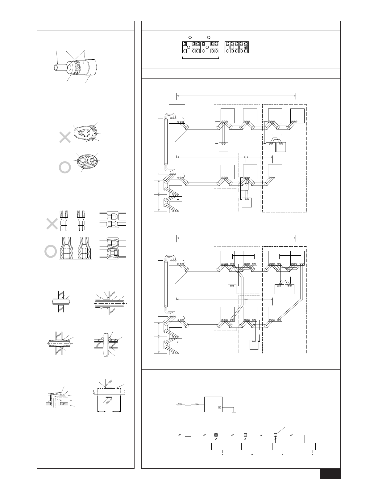
M1
S
M2
A
B
M1
S
M2
L1
L2 L3
N
TB3 TB7
A : Steel wire B: Piping
C : Asphaltic oily mastic or asphalt
D : Heat insulation material A
E : Outer covering B
A : Liquid pipe B : Gas pipe
C : Electric wire D : Finishing tape
E : Insulater
A : Sleeve B : Heat insulating material
C : Lagging D : Caulking material
E : Band F: Waterproofing laye
G : Sleeve with edge H : Lagging material
I : Mortar or other incombustible caulking
J : Incombustible heat insulation material
A : Power source
B : Transmission line
A : Group 1
B : Group 3
C : Group 5
D : Shielded Wire
E : Sub Remote
Controller
( ): Address
A : Switch (Breakers for Wiring and Current Leakage)
B : Outdoor Unit C : Pull Box
D : Indoor Unit
A
B
C
E
D
M1M2S
M1 M2 S
TB7
TB3
IC
(51)
M1 M2 S
TB5
RC
(01)
IC
M1 M2 S
TB5
(03)
IC
M1 M2 S
TB5
(02)
IC
M1 M2 S
TB5
(04)
IC
M1 M2 S
TB5
(05)
IC
M1 M2 S
TB5
(07)
IC
M1 M2 S
TB5
(06)
L
2
L
1
(101)
RC
(105)
RC
(104)
RC
(155)
OC
M1 M2 S
TB7
(53)
OC
r
3
M1M2S
Power Supply
Unit
M1M2S
MJ103
L
3
L
6
L
7
L
4
L
5
r
2
r
4
r
1
AB AB AB
AB
M1M2 S
TB3
A
B
C
E
D
M1 M2 S
TB7
IC
(51)
M1 M2 1 2S
TB5 TB15
12
TB15
12
TB15
12
TB15
12
TB15
12
TB15
12
TB15
MA
(01)
IC
M1 M2 S
TB5
(03)
IC
M1 M2 S
TB5
(02)
IC
M1 M2 S
TB5
(04)
IC
M1 M2 S
TB5
(05)
IC
M1 M2 S
TB5
(07)
IC
M1 M2 S
TB5
(06)
L
2
L
1
MAMAMA
OC
M1 M2 S
TB7
(53)
OC
c
1
c
4
c
3
S
Power Supply
Unit
S
MJ103
L
3
L
6
L
7
L
4
c
3
ABABAB
M1M2
M1M2
c
1
c
1
c
2
c
2
AB
M1M2S
TB3
M1M2S
TB3
 Loading...