

Mitsubishi Electric CITY MULTI PUHY-P-YMF-B Installation Manual
Air-Conditioners
OUTDOOR UNIT
PUHY-P-YMF-B
DEUTSCH
FRANÇAIS
NEDERLANDS
ENGLISH
ITALIANO
FOR INSTALLER
FÜR INSTALLATEURE
POUR L’INSTALLATEUR
VOOR DE INSTALLATEUR
PER L’INSTALLATORE
geprgeprüftefte
SicherheitSicherheit
INSTALLATION MANU AL
For safe and correct use, please read this installation manual thoroughly before installing the air-conditioner unit.
∗ Remote controller (PAR-F25MA) is available as an optional remote controller.
INSTALLATIONSHANDBUCH
Zum sicheren und ordnungsgemäßen Gebrauch der Klimageräte das Installationshandbuch gründlich durchlesen.
∗ Fernbedienung (PAR-F25MA) ist als Zubehör wahlweise erhältlich.
MANUEL D’INSTALLATION
Veuillez lire le manuel d’installation en entier avant d’installer ce climatiseur pour éviter tout accident et vous assurer d’une utilisation
correcte.
∗ La télécommande (PAR-F25MA) est disponible en option.
INSTALLATIEHANDLEIDING
Voor een veilig en juist gebruik moet u deze installatiehandleiding grondig doorlezen voordat u de airconditioner installeert.
∗ De afstandsbedieningseenheid (PAR-F25MA) is verkrijgbaar als een optioneel toe te voegen afstandsbediening.
MANUALE DI INSTALLAZIONE
Per un uso sicuro e corretto, leggere attentamente questo manuale di installazione prima di installare il condizionatore d’aria.
∗ Il comando a distanza (modello PAR-F25MA) disponibile in opzione.

Contents
1. Safety precautions ...................................................................... 3
1.1. Before installation and electric work ............................... 3
1.2. Precautions for devices that use R407C refrigerant.......3
1.3. Before getting installed ................................................... 4
1.4. Before getting installed (moved) - electrical work...........4
1.5. Before starting the test run ............................................. 4
2. Combination with indoor units..................................................... 5
3. Confirmation of parts attached ................................................... 5
4. Combination with outdoor units ................................................... 6
5. Selection of installation site ........................................................ 6
6. Space required around unit ........................................................ 6
6.1. Individual installation ...................................................... 6
6.2. Collective installation and continuous installation........... 7
7. Lifting method and weight of product.......................................... 8
8. Installation of unit........................................................................ 8
8.1. Location of anchor bolt ................................................... 8
8.2. Installation ...................................................................... 9
8.3. Connecting direction for refrigerant piping.................... 10
8.4. Noise level .................................................................... 10
9. Caution for snow and seasonal wind ........................................ 11
9.1. Snow and seasonal wind.............................................. 11
9.2. Countermeasure to seasonal wind ............................... 11
10. Refrigerant piping installation.................................................. 11
10.1. Areas of caution .......................................................... 12
10.2. Refrigerant piping system ........................................... 13
10.3. Caution for piping connection/valve operation ............ 15
10.4. How to install branch pipe ........................................... 16
10.5. Airtight test and evacuation, refrigerant charging........ 18
10.6. Thermal insulation of refrigerant piping....................... 21
11. Electrical work ......................................................................... 23
11.1. Caution........................................................................ 23
11.2. Control box and connecting position of wiring............. 24
11.3. Wiring transmission cables ......................................... 25
11.4. Wiring of main power supply and equipment
capacity ....................................................................... 31
12. Test run.................................................................................... 32
12.1. Checking before getting test run ................................. 32
12.2. Test run method .......................................................... 32
12.3. How to cope with test run abnormality ........................ 33
12.4. Coping with remote controller abnormality.................. 35
12.5. The following phenomena do not represent
abnormality (emergency) ............................................ 36
2
ENGLISH
3
ENGLISH
- Ask an authorized technician to install the accessories. Improper
installation by the user may result in water leakage, electric shock,
or fire.
• Never repair the unit. If the air conditioner must be repaired,
consult the dealer.
- If the unit is repaired improperly, water leakage, electric shock, or
fire may result.
• Do not touch the heat exchanger fins.
- Improper handling may result in injury.
• If refrigerant gas leaks during installation work, ventilate the
room.
- If the refrigerant gas comes into contact with a flame, poisonous
gases will be released.
• Install the air conditioner according to this Installation Manual.
- If the unit is installed improperly, water leakage, electric shock, or
fire may result.
• Have all electric work done by a licensed electrician according
to “Electric Facility Engineering Standard” and “Interior Wire
Regulations”and the instructions given in this manual and always use a special circuit.
- If the power source capacity is inadequate or electric work is per-
formed improperly, electric shock and fire may result.
• Securely install the outdoor unit terminal cover (panel).
- If the terminal cover (panel) is not installed properly, dust or water
may enter the outdoor unit and fire or electric shock may result.
• When installing and moving the air conditioner to another site,
do not charge the it with a refrigerant different from the refrigerant (R407C) specified on the unit.
- If a different refrigerant or air is mixed with the original refrigerant,
the refrigerant cycle may malfunction and the unit may be damaged.
• If the air conditioner is installed in a small room, measures must
be taken to prevent the refrigerant concentration from exceeding the safety limit even if the refrigerant should leak.
- Consult the dealer regarding the appropriate measures to prevent
the safety limit from being exceeded. Should the refrigerant leak
and cause the safety limit to be exceeded, hazards due to lack of
oxygen in the room could result.
• When moving and reinstalling the air conditioner, consult the
dealer or an authorized technician.
- If the air conditioner is installed improperly, water leakage, electric
shock, or fire may result.
• After completing installation work, make sure that refrigerant
gas is not leaking.
- If the refrigerant gas leaks and is exposed to a fan heater, stove,
oven, or other heat source, it may generate noxious gases.
• Do not reconstruct or change the settings of the protection devices.
- If the pressure switch, thermal switch, or other protection de vice is
shorted and operated forcibly, or parts other than those specified
by Mitsubishi Electric are used, fire or explosion may result.
• To dispose of this product, consult your dealer.
• The installer and system specialist shall secure safety against
leakage according to local regulation or standards.
- Following standards may be applicable if local regulation are not
available.
• Pay a special attention to the place, such as a basement, etc.
where refrigeration gas can stay, since refrigeration is heavier
than the air.
1.2. Precautions for devices that use
R407C refrigerant
Caution:
• Do not use the existing refrigerant piping.
- The old refrigerant and refrigerator oil in the existing piping con-
tains a large amount of chlorine which may cause the refrigerator
oil of the new unit to deteriorate.
• Use refrigerant piping made of C1220 (CU-DHP) phosphorus
deoxidized copper as specified in the JIS H3300 “Copper and
copper alloy seamless pipes and tubes”. In addition, be sure
that the inner and outer surfaces of the pipes are clean and free
1. Safety precautions
1.1. Before installation and electric work
s Before installing the unit, make sure you read all the
“Safety precautions”.
s The “Safety precautions” provide very important
points regarding safety. Make sure you follow them.
s This equipment may not be applicable to EN61000-3-
2: 1995 and EN61000-3-3: 1995.
s This equipment may cause the adverse effect on the
same supply system.
s Please report to or take consent by the supply author-
ity before connection to the system.
Symbols used in the text
Warning:
Describes precautions that should be observed to prevent danger
of injury or death to the user.
Caution:
Describes precautions that should be observed to prevent damage
to the unit.
Symbols used in the illustrations
: Indicates an action that must be avoided.
: Indicates that important instructions must be followed.
: Indicates a part which must be grounded.
: Indicates that caution should be taken with rotating parts. (This
symbol is displayed on the main unit label.) <Color: Yellow>
: Indicates that the main switch must be turned off before servicing.
(This symbol is displayed on the main unit label.) <Color: Blue>
: Beware of electric shock. (This symbol is displayed on the main
unit label.) <Color: Yellow>
: Beware of hot surface. (This symbol is displayed on the main unit
label.) <Color: Yellow>
ELV
: Please pay attention to electric shock fully because this is
not Safety Extra Low-Voltage (SELV) circuit.
And at servicing, please shut down the power supply for both
of Indoor Unit and Outdoor Unit.
Warning:
Carefully read the labels affixed to the main unit.
Warning:
• Ask the dealer or an authorized technician to install the air conditioner.
- Improper installation by the user may result in w ater leakage, elec-
tric shock, or fire.
• Install the air unit at a place that can withstand its weight.
- Inadequate strength may cause the unit to fall down, resulting in
injuries.
• Use the specified cables for wiring. Make the connections securely so that the outside force of the cable is not applied to the
terminals.
- Inadequate connection and fastening may gener ate heat and cause
a fire.
• Prepare for typhoons and other strong winds and earthquakes
and install the unit at the specified place.
- Improper installation may cause the unit to topple and result in in-
jury.
• Always use an air cleaner, humidifier, electric heater, and other
accessories specified by Mitsubishi Electric.

4
ENGLISH
of hazardous sulphur, oxides, dust/dirt, shaving particles, oils,
moisture, or any other contaminant.
- Contaminants on the inside of the refrigerant piping may cause the
refrigerant residual oil to deteriorate.
• Store the piping to be used during installation indoors and keep
both ends of the piping sealed until just before brazing. (Store
elbows and other joints in a plastic bag.)
- If dust, dirt, or water enters the refrigerant cycle, deterioration of
the oil and compressor trouble may result.
• Use ester oil, ether oil or alkylbenzene (small amount) as the
refrigerator oil to coat flares and flange connections.
- The refrigerator oil will degrade if it is mixed with a large amount of
mineral oil.
• Use liquid refrigerant to fill the system.
- If gas refrigerant is used to seal the system, the composition of the
refrigerant in the cylinder will change and performance may drop.
• Do not use a refrigerant other than R407C.
- If another refrigerant (R22, etc.) is used, the chlorine in the refriger-
ant may cause the refrigerator oil to deteriorate.
• Use a vacuum pump with a reverse flow check valve.
- The vacuum pump oil may flow back into the refrigerant cycle and
cause the refrigerator oil to deteriorate.
• Do not use the following tools that are used with conventional
refrigerants.
(Gauge manifold, charge hose, gas leak detector, reverse flow
check valve, refrigerant charge base, vacuum gauge, refrigerant recovery equipment)
- If the conventional refrigerant and refrigerator oil are mixed in the
R407C, the refrigerant may deteriorated.
- If water is mixed in the R407C , the refrigerator oil may deteriorate.
- Since R407C does not contain any chlorine, gas leak detectors for
conventional refrigerants will not react to it.
• Do not use a charging cylinder.
- Using a charging cylinder may cause the refrigerant to deteriorate.
• Be especially careful when managing the tools.
- If dust, dirt, or water gets in the refrigerant cycle, the refrigerant
may deteriorate.
1.3. Before getting installed
Caution:
• Do not install the unit where combustible gas may leak.
- If the gas leaks and accumulates around the unit, an explosion
may result.
• Do not use the air conditioner where food, pets, plants, precision instruments, or artwork are kept.
- The quality of the food, etc. may deteriorate.
• Do not use the air conditioner in special environments.
- Oil, steam, sulfuric smoke, etc. can significantly reduce the per-
formance of the air conditioner or damage its parts.
• When installing the unit in a hospital, communication station,
or similar place, provide sufficient protection against noise.
- The inverter equipment, private power generator, high-frequency
medical equipment, or radio communication equipment may cause
the air conditioner to operate erroneously , or f ail to operate. On the
other hand, the air conditioner may affect such equipment by creating noise that disturbs medical treatment or image broadcasting.
• Do not install the unit on a structure that may cause leakage.
- When the room humidity exceeds 80% or when the drain pipe is
clogged, condensation may drip from the indoor unit. Perform collective drainage work together with the outdoor unit, as required.
1.4. Before getting installed (moved) -
electrical work
Caution:
• Ground the unit.
- Do not connect the ground wire to gas or water pipes, lightning
rods, or telephone ground lines. Improper grounding may result in
electric shock.
• The reverse phase of L lines (L
1, L2, L3) can be detected (Error
cord : 4103), but the reverse phase of L lines and N line can be
not be detected.
- The some electric parts should be damaged when power is supplied under the miss wiring.
• Install the power cable so that tension is not applied to the cable.
- T ension ma y cause the cable to break and generate heat and cause
a fire.
• Install an leak circuit breaker, as required.
- If an leak circuit breaker is not installed, electric shock may result.
• Use power line cables of sufficient current carrying capacity
and rating.
- Cables that are too small may leak, generate heat, and cause a
fire.
• Use only a circuit breaker and fuse of the specified capacity.
- A fuse or circuit breaker of a larger capacity or a steel or copper
wire may result in a general unit failure or fire.
• Do not wash the air conditioner units.
- Washing them may cause an electric shock.
• Be careful that the installation base is not damaged by long use.
- If the damage is left uncorrected, the unit may fall and cause per-
sonal injury or property damage.
• Install the drain piping according to this Installation Manual to
ensure proper drainage. Wrap thermal insulation around the
pipes to prevent condensation.
- Improper drain piping may cause water leakage and damage to
furniture and other possessions.
• Be very careful about product transportation.
- Only one person should not carry the product if it weighs more than
20 kg.
- Some products use PP bands for packaging. Do not use any PP
bands for a means of transportation. It is dangerous.
- Do not touch the heat exchanger fins. Doing so may cut your fin-
gers.
- When transporting the outdoor unit, suspend it at the specified po-
sitions on the unit base. Also support the outdoor unit at four points
so that it cannot slip sideways.
• Safely dispose of the packing materials.
- Packing materials, such as nails and other metal or wooden parts,
may cause stabs or other injuries.
- Tear apart and throw aw ay plastic packaging bags so that children
will not play with them. If children pla y with a plastic bag which was
not torn apart, they face the risk of suffocation.
1.5. Before starting the test run
Caution:
• Turn on the power at least 12 hours before starting operation.
- Starting operation immediately after turning on the main power
switch can result in severe damage to internal parts. Keep the power
switch turned on during the operational season.
• Do not touch the switches with wet fingers.
- Touching a switch with wet fingers can cause electric shock.
• Do not touch the refrigerant pipes during and immediately after
operation.
- During and immediately after operation, the refrigerant pipes are
may be hot and may be cold, depending on the condition of the
refrigerant flowing through the refrigerant piping, compressor, and
other refrigerant cycle parts. Your hands may suffer burns or frostbite if you touch the refrigerant pipes.
• Do not operate the air conditioner with the panels and guards
removed.
- Rotating, hot, or high-voltage parts can cause injuries.
• Do not turn off the power immediately after stopping operation.
- Alwa ys wait at least five minutes before turning off the power. Oth-
erwise, water leakage and trouble may occur.
5
ENGLISH
Remote controller PAR-F 25MA
Prior to Ver. E After Ver. F
16 (32) 20 (40)
16 (32) 16 (32)
2. Combination with indoor units
The indoor units connectable to this unit are shown below.
Model name of connectable indoor unit
Outdoor unit model
name
PMFY-P25 · 32 · 40 · 63 VBM
PLFY- P32· 40 · 50 · 63 · 80 · 100 · 125 VKM
PLFY- P25· 32 · 40 · 50 · 63 · 80 · 100 · 125 VLMD
PEFY-P25 · 32 VML
PEFY-P40 · 50 · 63 · 71 · 80 · 100 · 125 · 140 · 200 · 250 VMH
PCFY-P40· 63 · 100 · 125 VGM
PKFY-P25 VAM
PKFY-P32 · 40 · 50 VGM
PFFY- P25 · 32 · 40 · 50 · 63 VLEM
PFFY- P25 · 32 · 40 · 50 · 63 VLRM
PDFY-P25· 32 · 40 · 50 · 63 · 71 · 80 · 100 · 125 VM
Total capacity of
connected indoor unit
models
Quantity of connectable
indoor unit
200 to 520PUHY-P400
2 to 20
250 to 650PUHY-P500
Note:
1. The total capacity of connected indoor unit models represents the total sum of the figures expressed in the indoor model name.
2. Combinations in which the total capacity of the connected indoor units exceeds the capacity of the outdoor unit will reduce the capacity
of each indoor unit below the rated capacity during simultaneous operation. Therefore, if circumstances allows, combine indoor units
within the capacity of the outdoor unit.
3. A transmission booster (RP) is required when the number of connected indoor unit models in a cooling system exceeds the number of
models specified in the chart below.
* The maximum number of units that can be controlled is determined by the indoor unit model, the type of remote controller and their
capabilities.
The number of indoor units and the total number of remote controllers is displayed within the parenthesis ( ).
*1 If even one unit that is higher than 200 exists in the cooling system, the maximum capacity will be “200 or higher”.
200 or lower
200 or higher
(*1)
Capability of the
connected indoor units
Number of connected indoor units that can be
connected without a RP.
Remote controller type
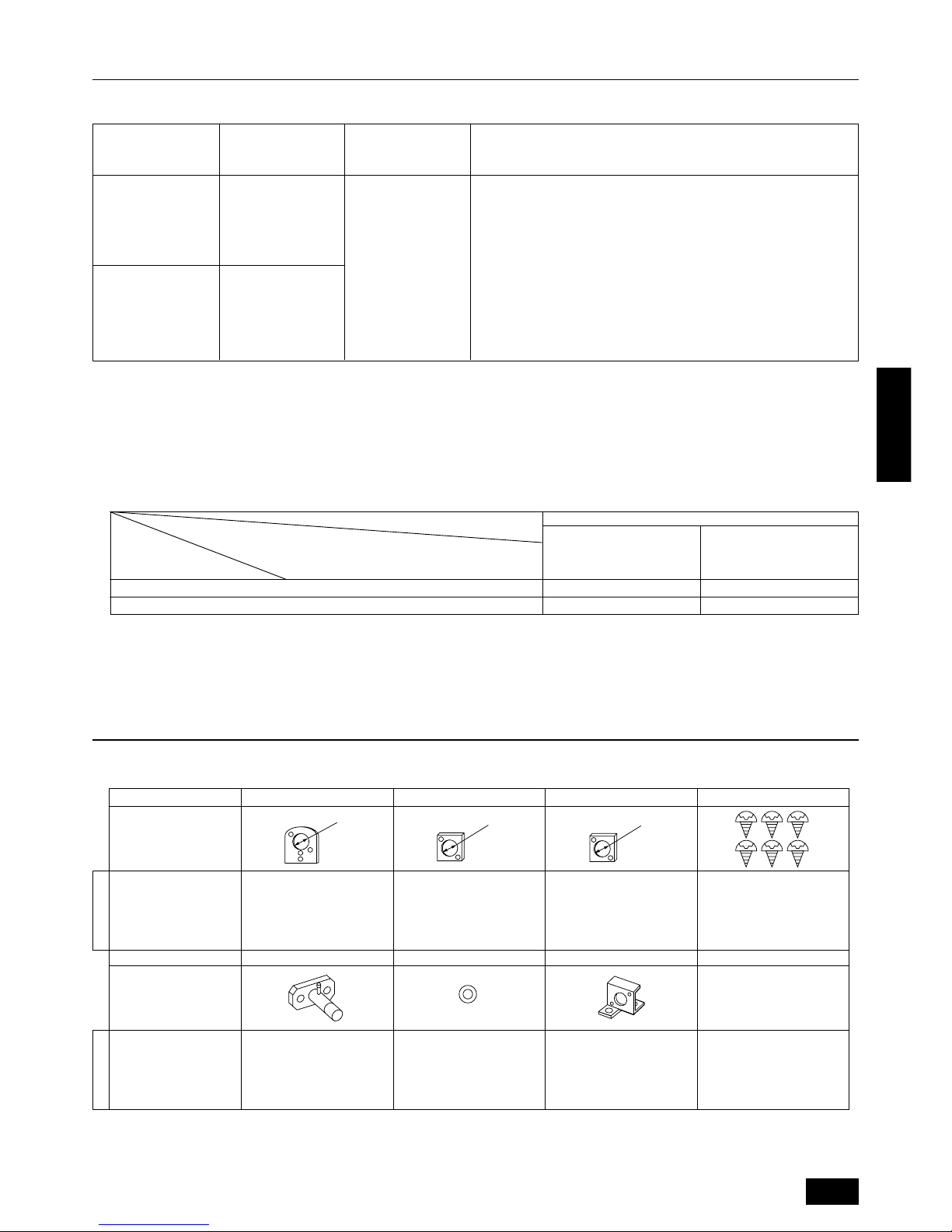
This outdoor unit is attached with the parts below. Please check the quantity for each item.
Name 1 Conduit mounting plate 2 Conduit mounting plate 3 Conduit mounting plate 4 Tapping screw M4 × 10
Shape
PUHY-P400
PUHY-P500
1116
Name 5 Connecting pipe 6 Packing 7 Wire mounting plate
Shape
PUHY-P400
PUHY-P500
111
*5 Connecting pipe is fixed with the unit.
3. Confirmation of parts attached
Model name
Model name
ø62
ø53
ø46
inside ø29, outside ø39
6
ENGLISH
Super Y
PUHY-P600YSMF-B
PUHY-P650YSMF-B
PUHY-P700YSMF-B
PUHY-P750YSMF-B
Constant capacity unit
PUHN-P200YMF-B
PUHN-P250YMF-B
PUHN-P200YMF-B
PUHN-P250YMF-B
Variable capacity unit
PUHY-P400YMF-B
PUHY-P500YMF-B
A Super Y (PUHY-P600/650/700/750YSMF-B) is produced when a Constant Capacity Unit (PUHN-P200/250YMF-B) is combined with this unit (PUHY P400/500YMF-B).
Refer to the installation manual that comes with the Constant Capacity Unit when this unit is used as a Super Y.
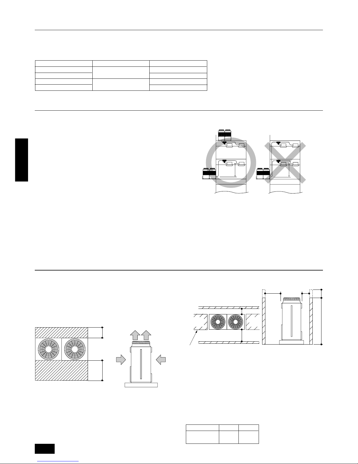
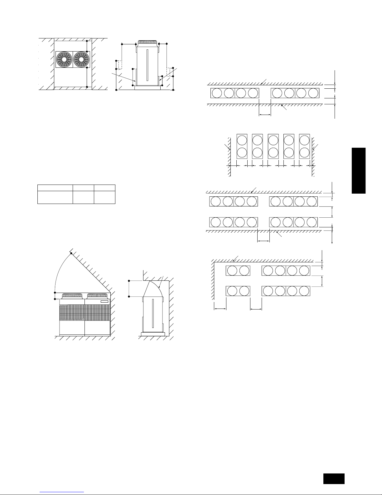
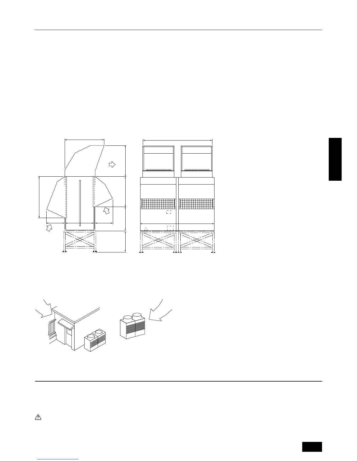
6.1. Individual installation
Basic space required
A space of at least 250 mm is necessary at the back for inlet air. Taking
servicing, etc. from the rear into account, a space of about 450 mm
should be provided, the same as at the front.
D
FE
C
B
A
<Top view> <Side view>
A 250 mm or more
B 450 mm or more
C Front (outside of machine room)
D Top discharge (open in principle)
E Front inlet (open in principle)
F Rear inlet (open in principle)
5. Selection of installation site
Select space for installing outdoor unit, which will meet the following
conditions:
• no direct thermal radiation from other heat sources
• no possibility of annoying neighbors by noise from unit
• no exposition to strong wind
• with strength which bears weight of unit
• note that drain flows out of unit when heating
• with space for air passage and service work shown below
Because of the possibility of fire, do not install unit to the space where
generation, inflow, stagnation, and leak of combustible gas is expected.
• Avoid unit installation in a place where acidic solution and spra y (sulfur)
are often used.
• When having cooling operation at an outside air temperature of below 10°C, in order to obtain steady operation of unit, select an installation site not exposed directly to rain and snow, or install air outlet
and inlet ducts. (Refer to Page 11.) Install the outdoor unit at the
same position on the same floor, or above, the indoor unit. (See the
figure at the right.)
• Do not use unit in any special environment where oil, steam and
sulfuric gas exist.
Installation restriction on outdoor unit when cooling operation is performed
when the outdoor air temperature is 10°C or lower
A
(Same floor as indoor unit, or floor above)
A 4 m or less
6. Space required around unit
When inlet air enters from right and left sides of unit
C
C
D
A
A
B
Hh
B
<Side view>
A L1 or more
B L
2 or more
C Front
D No restrictions on wall height (left and right)
Note:
• Wall heights (H) of the front and the back sides shall be within
overall height of unit.
• When the total height is exceeded, add the “h” dimension of the
figure above to L1 and L2 in the table above.
Model L1 L2
PUHY-P400
450 250
PUHY-P500
4. Combination with outdoor units
7
ENGLISH
When unit is surrounded by walls
C
B
A
B
650
325
A
C
H
h
Hh
D
E
<Side view>
A L
1 or more
B L
2 or more
C Front
D Front panel
E Rear panel
Note:
• Wall heights (H) of the front and the back sides shall be within
height of front panel and rear panel.
• If the panel height is exceeded, add the “h” dimension of the
figure above to L1 and L2 in the table above.
Model L1 L2
PUHY-P400
450 250
PUHY-P500
Example: When h is 100
The L1 dimension becomes 450+100=550 mm.
When there is an obstruction above the unit
A
E
D
CF
B
When there is little space
up to an obstruction
A 45° or more
B 300 mm or more
C Front
D 1000 mm or more
E Air outlet guide (Procured at the site)
F Rear
6.2. Collective installation and continuous installation
Space required for collective installation and continuous installation:
When installing several units, leave the space between each block as
shown below considering passage for air and people.
B
CC
D
AA
*E
*F
B
B
A
A
*FF F F F*E
B
CCCCC
D
B
E
GCC
B
A
E
A
B
CG
E
A
C
DD
A
A (Must be open)
B Wall height (H)
C Front
D 1000 mm or more
E 250 mm or more
F 450 mm or more
G 900 mm or more
Note:
• Open in the two directions.
• In case wall height (H) exceeds overall height of unit, add “h”
dimension (h=wall height <H> – overall height of unit) to * marked
dimension.
• If there is a wall at both the front and the rear of the unit, install
up to three units consecutively in the side direction and provide
a space of 1000 mm or more as inlet space/passage space for
each three units.
8
ENGLISH
Weight of product:
PUHY-P400 PUHY-P500
455 kg 475 kg
Caution:
Be very careful to carry product.
- Do not have only one person to carry product if it is more than 20 kg.
- PP bands are used to pack some products. Do not use them as a
mean for transportation because they are dangerous.
- Do not touch heat exchanger fins with your bare hands . Otherwise you
may get a cut in your hands.
- Tear plastic packaging bag and scrap it so that children cannot play
with it. Otherwise plastic packaging bag ma y suffocate children to death.
- When carrying in outdoor unit, be sure to support it at four points. Car-
rying in and lifting with 3-point support may make outdoor unit unstable, resulting in a fall of it.
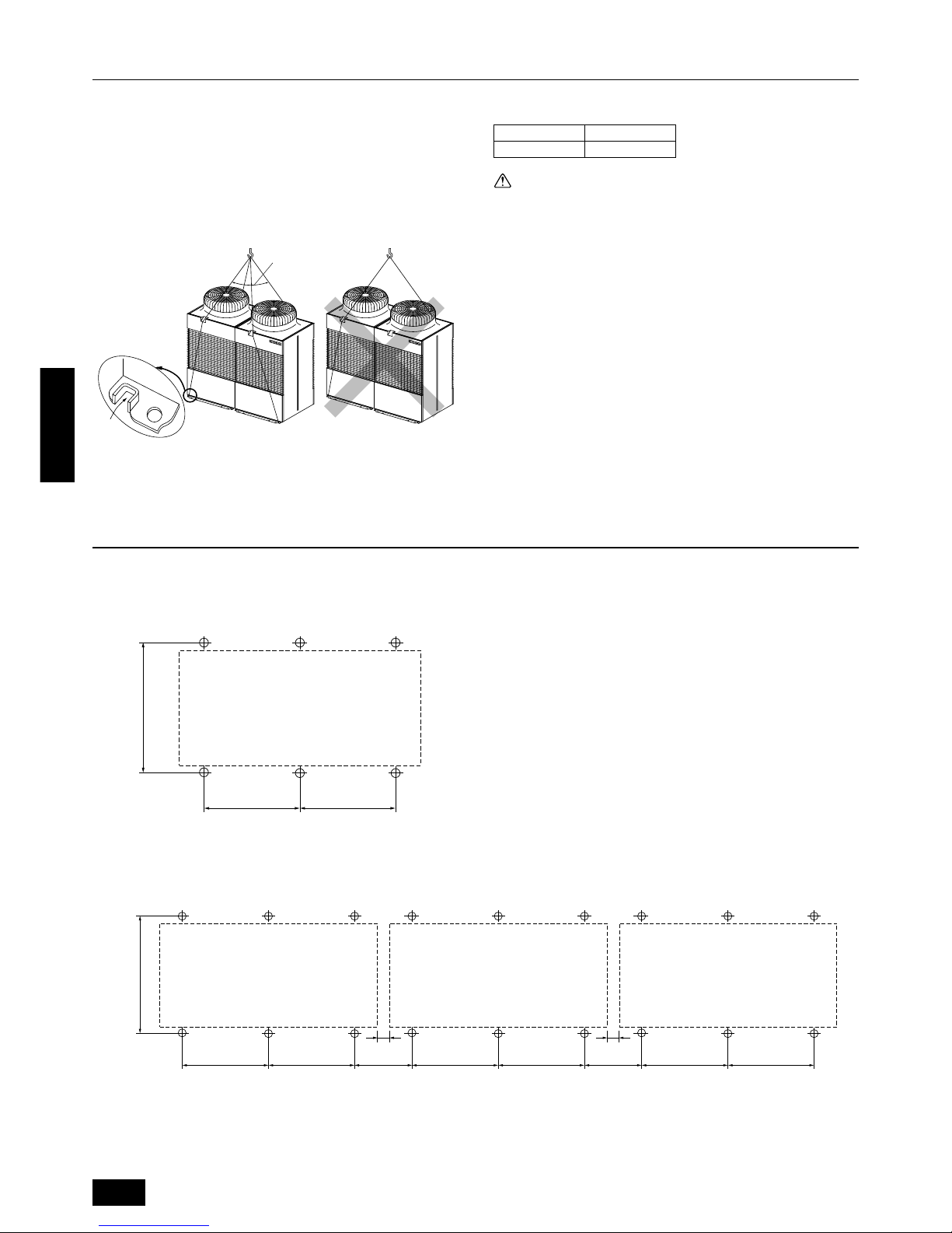
7. Lifting method and weight of product
8.1. Location of anchor bolt
• Individual installation
• Example of collective installation
10 10
780±2
880±5
780±2 440 440780±2 780±2 780±2 780±2
For collective installation, provide a 10 mm gap between units.
A (Service side)
8. Installation of unit
Dangerous!
• When carrying the unit suspended, pass the ropes under the unit
and use the two suspension points each at the front and rear.
• Always lift the unit with ropes attached at four points so that impact is
not applied to the unit.
• Attach the ropes to the unit at an angle of 40° or less.
• Use two ropes at least 8 m long.
B
A
A 40° or less
B Rope suspension part
780±2
880±5
A
780±2
9
ENGLISH
80 82 78
80
694
73
90
780
B
780
B
1760
C
1990
D
840 E
880 B
15
910
5656
A
F
150
Ø62
Ø27
230
111
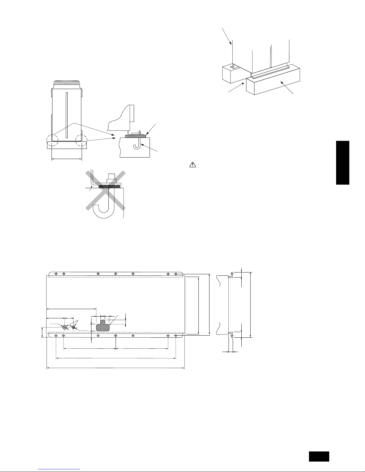
8.2. Installation
• Fix unit tightly with bolts as shown below so that unit will not fall down
due to earthquake or gust.
• Use concrete or angle for foundation of unit.
• Vibration may be transmitted to the installation section and noise
and vibration may be generated from the floor and walls, depending
on the installation conditions. Therefore, provide ample
vibrationproofing (cushion pads, cushion frame, etc.).
880±5
A
B
C
Down piping and down wiring precautions
When down piping and down wiring are performed, be sure that foundation and base work does not block the base through holes. When down
piping is performed, make the foundation at least 100 mm high so that
the piping can pass under the bottom of the unit.
A Bottom piping through hole
B (bolt hole)
C (bolt hole for old models)
D (unit width)
E (unit depth)
F Bottom wiring through hole
D
E
F
A Be sure that the corners are firmly seated. If the corners are not firmly
seated, the installation feet may be bent.
B M10 anchor bolt procured at the site
C Corner is not seated.
D Unit
(Provide ample vibrationproofing between the unit and the foundation by
using cushion pads, cushion frame, etc.)
E Piping and wiring space (Bottom piping, bottom wiring)
F Concrete foundation
Warning:
• Be sure to install unit in a place strong enough to withstand its
weight.
Any lack of strength may cause unit to fall down, resulting in a
personal injury.
• Have installation work in order to protect against a str ong wind
and earthquake.
Any installation deficiency may cause unit to fall down, resulting in a personal injury.
When building the foundation, give full attention to the floor strength,
drain water disposal <during operation, drain water flows out of the unit>,
and piping and wiring routes.
10
ENGLISH
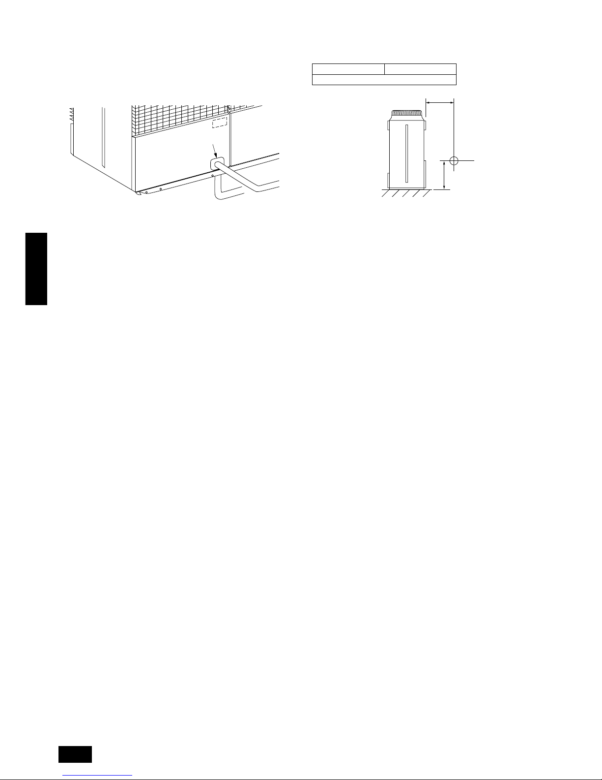
8.3. Connecting direction for refrigerant
piping
Two connecting directions are available f or refrigerant piping of the outdoor unit, bottom piping and front piping, as shown below:
C
A
B
A Knock-out hole
B Bottom piping
C Front piping
Note:
In the case of bottom piping, build a 100 mm or higher foundation
so that piping will go through the bottom of the unit.
8.4. Noise level
(50/60Hz)
PUHY-P400 PUHY-P500
60/61 dB(A)
1m
1m
A
B
A Front
B Measuring point
Measuring location: a room free from echoes and reverberations
11
ENGLISH
9. Caution for snow and seasonal wind
In cold and/or snowy areas, sufficient countermeasures to wind and snow
damages should be taken for operating unit in normal and good condition in winter time. Ev en in the other areas, full consider ation is required
for installation of unit in order to prevent abnormal operations caused by
seasonal wind or snow. When rain and snow directly fall on unit in
the case of air-conditioning operations in 10 or less degrees centigrade outdoor air, mount inlet and outlet ducts on unit for assuring
stable operations.
9.1. Snow and seasonal wind
■ Prevention of wind and snow damages in cold or snowy areas:
Refer to the figure of snow hood shown below:
• Snow hood
A Outlet
B Inlet
9.2. Countermeasure to seasonal wind
Referring to the figure shown below, take appropriate measures which
will suit the actual situation of the place for installation.
AA
A Seasonal wind
Note:
1. Height of frame base for snow damage prevention (H) shall be
twice as high as expected snowfall. Width of frame base shall
not exceed that of the unit. The frame base shall be made of
angle steel, etc., and designed so that sno w and wind slip through
the structure. (If frame base is too wide, snow will be accumulated on it.)
2. Install unit so that seasonal wind will not directly lash against
openings of inlet and outlet ducts.
3. Build frame base at customer referring to this figure.
Material : Galvanized steel plate 1.2T
Painting : Overall painting with polyester powder
Color : Munsell 5Y8/1 (same as that of unit)
4. When the unit is used in a cold region and the heating operation
is continuously performed for a long time when the outside air
temperature is below freezing, install a heater to the unit base
or take other appropriate measures to prevent water from freezing on the base.
H
500(840)500
1145
(670) 821 903
1093
A
B
B
1888
(1990)
10. Refrigerant piping installation
Connecting the piping is a terminal-branch type in which refrigerant piping from the outdoor unit is branched at the terminal and connected to each of
the indoor units.
The method of connection consists of flare connections at the indoor units, flange connections for the piping of the outdoor unit and flare connections
for the liquid piping. Note that the branched sections are brazed.
Warning:
Always use extreme care to prevent the refrigerant gas (R22) from leaking while using fire or flame. If the refrigerant gas comes in contact
with the flame from any source, suc h as a gas stove, it breaks down and generates a poisonous gas which can cause gas poisoning. Never
weld in an unventilated room. Always conduct an inspection for gas leakage after installation of the refrigerant piping has been completed.
12
ENGLISH
6 If the diameters of the branch piping of the designated refrigerant piping differs, use a pipe cutter to cut the connecting section and then use an
adapter for connecting different diameters to connect the piping.
7 Always observe the restrictions on the refrigerant piping (such as rated length, the difference between high/low pressures, and piping diameter).
Failure to do so can result in equipment failure or a decline in heating/cooling performance.
8 A second branch cannot be made after a header branch. (These are shown by ×.)
A
A
B
A To Outdoor Unit
B Capped Piping
9 Always use good-quality materials for brazing.
0 The City Multi Series Y will stop due an abnormality due to excessive or insufficient coolant. At such a time, alw ays properly charge the unit. When
servicing, always check the notes concerning pipe length and amount of additional refrigerant at both locations, the refrigerant volume calculation
table on the back of the service panel and the additional refrigerant section on the labels for the combined number of indoor units. (Refer to Pages
13
to 14.)
A Use liquid refrigerant to fill the system.
B Never use refrigerant to perform an air purge. Always evacuate using a vacuum pump.
C Always insulate the piping properly. Insufficient insulation will result in a decline in heating/cooling performance, water drops from condensation
and other such problems. (Refer to Pages 21 to
22
.)
D When connecting the refrigerant piping, make sure the ball valve of the outdoor unit is completely closed (the factory setting) and do not operate it
until the refrigerant piping for the outdoor and indoor units has been connected, a refrigerant leakage test has been performed and the evacuation
process has been completed.
E Always use a non-oxidizing brazing material for brazing the parts. If a non-oxidizing brazing material is not used, it could cause clogging or damage
to the compressor unit. (Details of the piping connections and valve operation can be found on Pages 15 to 16.)
F Never perform outdoor unit piping connection work when it is raining.
Warning:
When installing and moving the air conditioner to another site, do not charge the it with a refrigerant different from the refrigerant (R407C)
specified on the unit.
- If a different refrigerant or air is mixed with the original refrigerant, the refrigerant cycle may malfunction and the unit may be damaged.
Caution:
• Use refrigerant piping made of C1220T-OL phosphorus deoxidized copper. In addition, be sure that the inner and outer surfaces of the
pipes are clean and free of hazardous sulphur, oxides, dust/dirt, shaving particles, oils, moisture, or any other contaminant.
- Contaminants on the inside of the refrigerant piping may cause the refrigerant residual oil to deteriorate.
• Use liquid refrigerant for sealing.
- Sealing with gas refrigerant will change the composition of the refrigerant in the cylinder and reduce the unit’s perf ormance.
• Never use existing refrigerant piping.
- The large amount of chlorine in conventional refrigerant and refrigerator oil in the existing piping will cause the new refrigerant to deteriorate.
• Store the piping to be used during installation indoors and keep both ends of the piping sealed until just before brazing.
- If dust, dirt, or water gets into the refrigerant cycle, the oil will deteriorate and the compressor may fail.
• Do not use a charging cylinder.
- Using a charging cylinder may cause the refrigerant to deteriorate.
Total of units down-
stream more than 331
Total of units down-
stream less than 160
Total of units down-
stream 161 to 330
10.1. Areas of caution
1 Use the following materials for refrigeration piping.
• Material: Seamless phosphorous deoxidized copper pipe, C1220T-OL or C1220T-O (Note: C1220T-OL is preferred.)
• Size: Refer to Pages
13
to 14.
2 Commercially available piping often contains dust and other materials. Always blow it clean with a dry inert gas.
3 Use care to prevent dust, water or other contaminants from entering the piping during installation.
4 Reduce the number of bending portions as much as possible, and make bending radius as big as possible.
5 Always use the branch piping set shown below, which are sold separately.
Branch pipe set name
Line branching Header branching
4 branching 7 branching 10 branching
CMY-Y102S-F CMY-Y102L-F CMY-Y202-F CMY-Y104-E CMY-Y107-E CMY-Y1010-E
13
ENGLISH
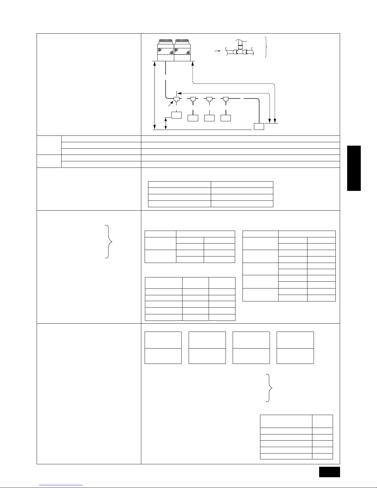
10.2. Refrigerant piping system
Permissible High/
Low Difference
Permissible
Length
A+B+C+D+a+b+c+d+e is 220 m or less
A+B+C+D+e is 100 m or less
B+C+D+e is 30 m or less
50 m or less (If the outdoor unit is lower, 40 m or less)
15 m or less
Select the branch kit, sold separately , from the tab le below. (Each kit contains a refrigerant and
gas piping set.)
Downstream Unit Model Total Branch Kit Model
160 or less CMY-Y102S-F
161 to 330 CMY-Y102L-F
331 or more CMY-Y202-F
(1) Refr igerant Piping Diameter In Section
From Outdoor Unit to First Branch (Outdoor Unit Piping Diameter)
Model Piping Diameter (mm)
PUHY-P400
Liquid Line ø15.88
Gas Line ø31.75
PUHY-P500
Liquid Line ø15.88
Gas Line ø38.1
<Additional Charge>
Liquid pipe size
Total length of
ø15.88 × 0.25
(m) × 0.25 (kg/m)
Liquid pipe size
Total length of
ø12.7 × 0.12
(m) × 0.12 (kg/m)
Liquid pipe size
Total length of
ø9.52 × 0.06
(m) × 0.06 (kg/m)
Liquid pipe size
Total length of
ø6.35 × 0.024
(m) × 0.024 (kg/m)
++++ α
At the conditions
below:
Each
Section of
Piping
Line-Branch Method
Connection Examples
(Connecting to Five Indoor Units)
Total Piping Length
Farthest Piping Length (L)
Farthest Piping Length After First Branch (r)
High/Low Difference in Indoor/Outdoor Section (H)
High/Low Difference in Indoor/Indoor Section (h)
■ Selecting the Refrigerant Branch Kit
Use the table to the right to make the selection
based on the model total of indoor units downstream from the branch section.
■ Select Each Section of Refrigerant Piping
(1) Section From Outdoor Unit
to First Branch (A)
(2) Sections From Branch to
Indoor Unit (a,b,c,d,e)
(3) Section From Branch to
Branch (B, C, D)
Select the size from the table to the right.
■ Additional Refrigerant Charge
At the time of shipping, the outdoor unit PUHY -P400
is charged with 16 kg of refrigerant and the PUHYP500 is charged with 22 kg. As this charge does not
include the amount needed for extended piping, additional charging for each refrigerant line will be required on site. In order that future servicing may be
properly provided, always keep a record of the size
and length of each refrigerant line and the amount of
additional charge by writing it in the space provided
on the outdoor unit.
■ Calculation of Additional Refrigerant Charge
• Calculate the amount of additional charge based
on the length of the piping extension and the size
of the refrigerant line.
• Use the table to the right as guide to calculating
the amount of additional charging and charge the
system according.
• If the calculation results of the calculation result
in a fraction of less than 0.1 kg, round up to the
next 0.1 kg. For e xample , if the result of the calculation was 16.76 kg, round the result up to 16.8
kg.
<Example>
Indoor 1 : 125 A : ø15.88 40 m a : ø9.52 10 m
2 : 100 B : ø12.7 10 m b : ø9.52 10 m
3:50 C:ø12.7 5 m c : ø9.52 10 m
4:32 D:ø9.52 5 m d : ø6.35 5 m
5:32 e:ø6.35 10 m
The total length of each liquid line is as follows:
ø15.88 : A = 40 m
ø12.7 : B + C = 10 + 5 = 15 m
ø9.52 : D + a + b + c = 5 + 10 + 10 + 10 = 35 m
ø6.35 : d + e = 5 + 10 = 15 m
Therefore,
<Calculation example>
Additional
refrigerant charge = 40 × 0.25 + 15 × 0.12 + 35 × 0.06
+ 15 × 0.024 + 2.5 = 16.8 kg
Note:
The model total for down-
stream units shown in the
table below is the model
total when viewed from
Point A in the drawing
above.
A Outdoor Unit
B First Branch
The first branch on the
outdoor unit must be
the CMY-Y202-F.
C Indoor unit
D To downstream units
Value of α
Total capacity of
connecting indoor units
α
to Model 80 1.0 kg
Models 81 to 160 1.5 kg
Models 161 to 330 2.0 kg
Models 331 to 480 2.5 kg
Models 481 or more 3.0 kg
A
B
L
R
H
A
A
B C D
e
a b c d
h
C
C
5
1
C2C3C
4
D
(2) Refr igerant Piping Diameter In Section
From Branch to Indoor Unit (Indoor Unit
Piping Diameter)
Model number Piping dia. (mm)
25 · 32 · 40
Liquid Line ø6.35
Gas Line ø12.7
50 · 63 · 71 · 80
Liquid Line ø9.52
Gas Line ø15.88
100 · 125 · 140
Liquid Line ø9.52
Gas Line ø19.05
200
Liquid Line ø12.7
Gas Line ø25.4
250
Liquid Line ø12.7
Gas Line ø28.58
Gas Line
(mm)
ø15.88
ø19.05
ø25.4
ø31.75
ø38.1
(3) Refr igerant Piping Diameter In Section
From Branch to Branch
Liquid Line
(mm)
ø9.52
ø12.7
ø12.7
ø15.88
ø15.88
Downstream Unit
Model T otal
80 or less
81 to 160
161 to 330
331 to 480
481 or more
14
ENGLISH
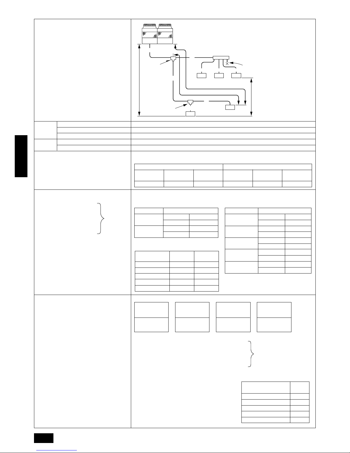
Permissible High/
Low Difference
Permissible
Length
A+B+C+a+b+c+d+e is 220 m or less
A+B+b is 100 m or less
B+b is 30 m or less
50 m or less (If the outdoor unit is lower, 40 m or less)
15 m or less
Select the branch kit, sold separately , from the tab le below. (Each kit contains a refrigerant and
gas piping set.)
Line branching Header branching
CMY-Y102S-F CMY-Y102L-F CMY-Y202-F CMY-Y104-E CMY-Y107-E CMY-Y1010-E
(1) Refr igerant Piping Diameter In Section
From Outdoor Unit to First Branch (Outdoor Unit Piping Diameter)
Model Piping Diameter (mm)
PUHY-P400
Liquid Line ø15.88
Gas Line ø31.75
PUHY-P500
Liquid Line ø15.88
Gas Line ø38.1
Total of units downstream
less than 160
Total of units downstream
161 to 330
4 branching
header
7 branching
header
10 branching
header
Liquid pipe size
Total length of
ø15.88 × 0.25
(m) × 0.25 (kg/m)
Liquid pipe size
Total length of
ø12.7 × 0.12
(m) × 0.12 (kg/m)
Liquid pipe size
Total length of
ø9.52 × 0.06
(m) × 0.06 (kg/m)
Liquid pipe size
Total length of
ø6.35 × 0.024
(m) × 0.024 (kg/m)
++++ α
<Example>
Indoor 1 : 125 A : ø15.88 30 m a : ø9.52 10 m
2 : 100 B : ø12.7 10 m b : ø9.52 20 m
3:40 C:ø12.7 15 m c : ø6.35 10 m
4:32 d:ø6.35 10 m
5:32 e:ø6.35 10 m
The total length of each liquid line is as follows:
ø15.88 : A = 30 m
ø12.7 : B + C = 10 + 15 = 25 m
ø9.52 : a + b = 10 + 20 = 30 m
ø6.35 : c + d + e = 10 + 10 + 10 = 30 m
Therefore,
<Calculation example>
Additional
refrigerant charge = 30 × 0.25 + 15 × 0.12 + 30 × 0.06
+ 30 × 0.024 + 2.5 = 14.4 kg
Value of α
Total capacity of
connecting indoor units
α
to Model 80 1.0 kg
Models 81 to 160 1.5 kg
Models 161 to 330 2.0 kg
Models 331 to 480 2.5 kg
Models 481 or more 3.0 kg
At the conditions
below:
<Additional Charge>
Each
Section of
Piping
Multiple Line/Header
Connection Example
(When Connecting Five Indoor Units)
Total Piping Length
Farthest Piping Length (L)
Farthest Piping Length After First Branch (r)
High/Low Difference in Indoor/Outdoor Section (H)
High/Low Difference in Indoor/Indoor Section (h)
■ Selecting the Refrigerant Branch Kit
Use the table to the right to make the selection
based on the model total of indoor units downstream from the branch section or on the number
of indoor units to be connected on the header
branch.
■ Select Each Section of Refrigerant Piping
(1) Section From Outdoor Unit
to First Branch (A)
(2) Sections From Branch to
Indoor Unit (a,b,c,d,e)
(3) Section From Branch to
Branch (B, C)
Select the size from the table to the right.
■ Additional Refrigerant Charge
At the time of shipping, the outdoor unit PUHYP400 is charged with 16 kg of refrigerant and the
PUHY -P500 is charged with 22 kg. As this charge
does not include the amount needed for extended
piping, additional charging for each refrigerant
line will be required on site. In order that future
servicing may be properly provided, always keep
a record of the size and length of each refrigerant line and the amount of additional charge by
writing it in the space provided on the outdoor
unit.
■ Calculation of Additional Refrigerant Charge
• Calculate the amount of additional charge
based on the length of the piping extension
and the size of the refrigerant line.
• Use the table to the right as guide to calculating the amount of additional charging and
charge the system according.
• If the calculation results of the calculation result in a fraction of less than 0.1 kg, round up
to the next 0.1 kg. For example, if the result
of the calculation was 14.32 kg, round the
result up to 14.4 kg.
Total of units downstream
more than 331
Note:
• Branch piping cannot be used
again after the header branch.
• The model total for downstream units shown in the table below is the model total
when viewed from Point A in
the drawing above.
A Outdoor Unit
B First Branch (Branch Joint)
The first branch must be the
CMY-Y202-F when the outdoor unit and header branch
are to be used.
C Branch Joint
D Indoor Unit
E Branch Header
F Cap
A
L
R
H
A
C
B
c
d
h
e
b
D
B
D
D
D
C
D
5
1
2
34
F
E
a
Gas Line
(mm)
ø15.88
ø19.05
ø25.4
ø31.75
ø38.1
(3) Refr igerant Piping Diameter In Section
From Branch to Branch
Liquid Line
(mm)
ø9.52
ø12.7
ø12.7
ø15.88
ø15.88
Downstream Unit
Model T otal
80 or less
81 to 160
161 to 330
331 to 480
481 or more
(2) Refrigerant Piping Diameter In Section
From Branch to Indoor Unit (Indoor Unit
Piping Diameter)
Model number Piping dia. (mm)
25 · 32 · 40
Liquid Line ø6.35
Gas Line ø12.7
50 · 63 · 71 · 80
Liquid Line ø9.52
Gas Line ø15.88
100 · 125 · 140
Liquid Line ø9.52
Gas Line ø19.05
200
Liquid Line ø12.7
Gas Line ø25.4
250
Liquid Line ø12.7
Gas Line ø28.58
15
ENGLISH
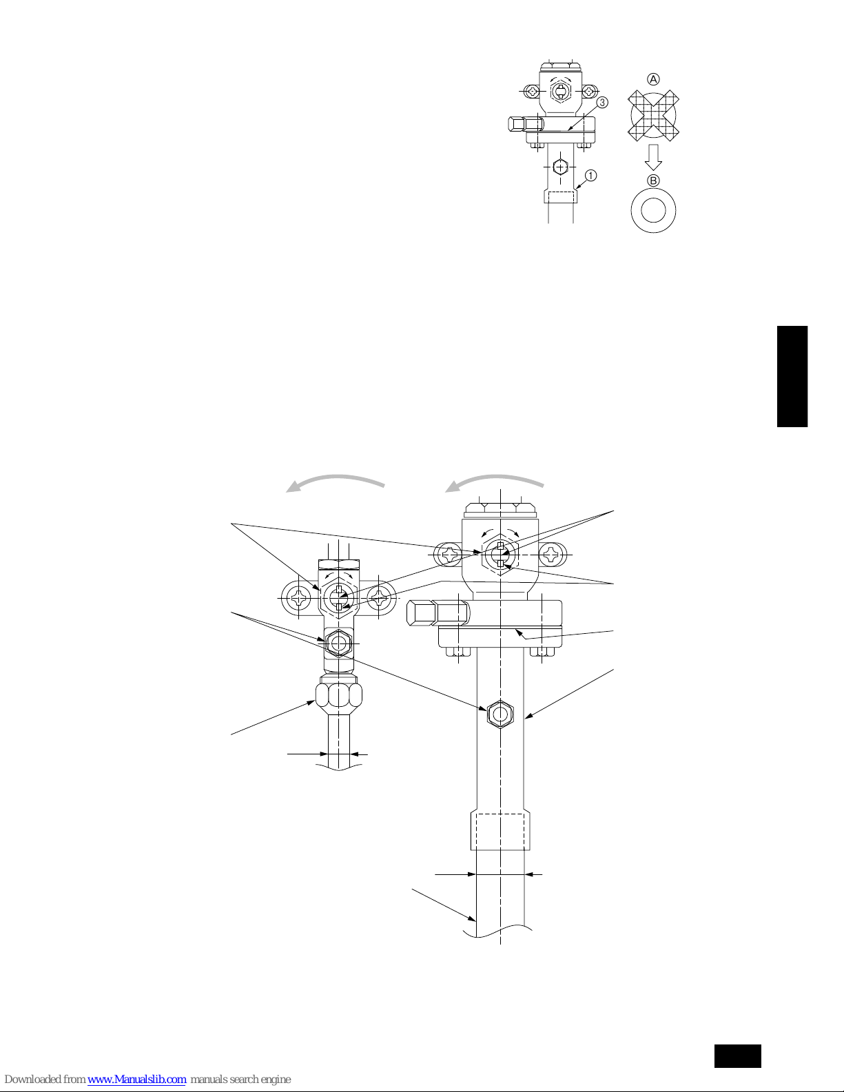
10.3. Caution f or piping connection/valve
operation
• Conduct piping connection and valve operation accurately by f ollo w-
ing the figure below.
• The gas side connecting pipe is being assembled for shipment.
(See the figure at the right.)
1 For brazing to the connecting pipe with flange, remove the con-
necting pipe with flange from the ball valve, and braze it at the
outside of the unit.
2 During the time when removing the connecting pipe with flange,
remove the seal attached on the back side of this sheet and paste
it onto the flange surface of the ball valve to prevent the entry of
dust into the valve.
3 The refrigerant circuit is closed with a round, close-packed pack-
ing at the shipment to prevent gas leak between flanges. As no
operation can be done under this state, be sure replace the packing with the hollow packing attached at the piping connection.
4 At the mounting of the hollow packing, wipe off dust attached on
the flange sheet surface and the packing. Coat refrigerating machine oil onto both surfaces of the packing.
A Replace the close-packed packing
B Hollow packing
• After evacuation and refrigerant charge, ensure that the handle is
fully open. If operating with the valve closed, abnormal pressure will
be imparted to the high- or low-pressure side of the refrigerant circuit, giving damage to the compressor, four-w ay valve, etc.
• Determine the amount of additional refrigerant charge by using the
formula, and charge refrigerant additionally through the service port
after completing piping connection work.
• After completing work, tighten the service port and cap securely not
to generate gas leak.
[Ball valve (liquid side)] [Ball valve (gas side)]
(This figure shows the valve in the fully open state.)
EE
O
S
O
S
I
K
J
H
G
F
A
B
C
D
A
B
1
3
16
ENGLISH
A Valve stem
[Fully closed at the factory, when connecting the piping, when evacuating,
and when charging additional refrigerant. Open fully after the operations
above are completed.]
B Stopper pin [Prevents the valve stem from turning 90° or more.]
C Packing (Accessory)
D Connecting pipe (Accessory)
[Use packing and securely install this pipe to the valve flange so that gas
leakage will not occur. (Tightening torque: 43 N·m (430 kg-cm)) Coat both
surfaces of the packing with refrigerator oil.]
E Open (Operate slowly)
F Cap, copper packing
[Remove the cap and operate the valve stem. Always reinstall the cap after
operation is completed. (Valve stem cap tightening torque: 25 N·m (250
kg-cm) or more)]
G Service port
[Use this port to evacuate the refrigerant piping and add an additional charge
at the site.
Open and close the port using a double-ended wrench.
Always reinstall the cap after operation is completed. (Service port cap
tightening torque: 14 N·m (140 kg-cm) or more)]
H Flare nut
[Tightening torque: 80 N·m (800 kg-cm)
Loosen and tighten this nut using a double-ended wrench.
Coat the flare contact surface with refrigerator oil.]
I ø15.88
J ø31.75 (PUHY-P400)
ø38.1 (PUHY-P500)
K Field piping
[Braze to the connecting pipe. (When brazing, use unoxidized brazing.)]
Appropriate tightening torque by torque wrench
Copper pipe external dia. (mm) Tightening torque (N·m) / (kg-cm)
ø6.35 14 to 18 / 140 to 180
ø9.52 35 to 42 / 350 to 420
ø12.7 50 to 57.5 / 500 to 575
ø15.88 75 to 80 / 750 to 800
ø19.05 100 to 140 / 1000 to 1400
Tightening angle standard
Pipe diameter (mm) Tightening angle (°)
ø6.35, ø9.52 60 to 90
ø12.7, ø15.88 30 to 60
ø19.05 20 to 35
Note:
If a torque wrench is not available, use the following method as a
standard.
When you tighten the flare nut with a wrench, y ou will reach a point
where the tightening torque will abrupt increase. Turn the flare nut
beyond this point by the angle shown in the table above.
Caution:
• Always remove the connecting pipe from the ball valve and braze
it outside the unit.
- Brazing the connecting pipe while it is installed will heat the ball
valve and cause trouble or gas leakage. The piping, etc. inside the
unit may also be burned.
• Use ester oil, ether oil or alkylbenzene (small amount) as the
refrigerator oil to coat flares and flange connections.
- The refrigerator oil will degrade if it is mixed with a large amount of
mineral oil.
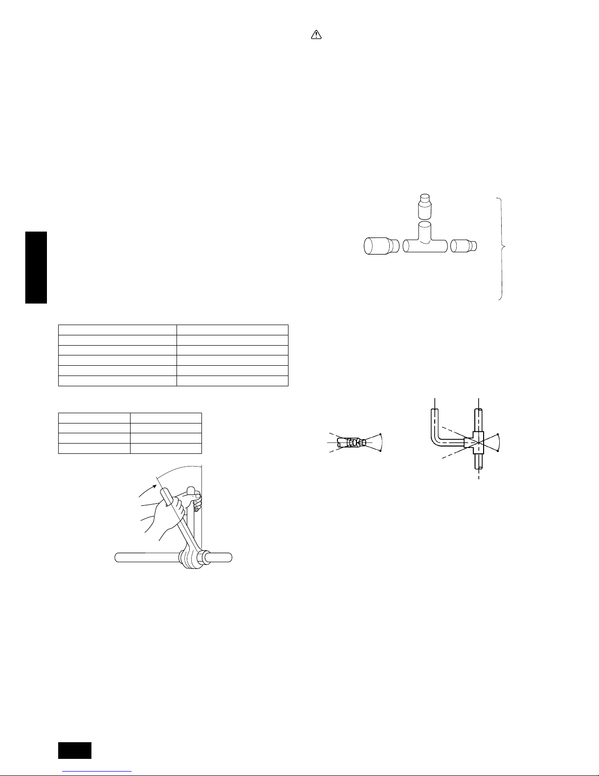
10.4. How to install branch pipe
For detail, please observe the instruction manual attached to the optional refrigerant branch kit.
■ Joint
B
A
A To Outdoor Unit
B To Branch Piping or Indoor Unit
• Apart from the CMY -Y202-F gas side, there are no restrictions on the
posture for attaching joints.
• Ensure that the branch pipes for the CMY-Y202-F gas side are attached horizontally or facing upwards. (See the diagram below.)
Horizontal Facing upwards
(Facing downwards is not possible)
• There is no limitation on the joint mounting configuration.
• If the diameter of the refrigerant piping selected by the procedures
described on pages 13 to 14 is different from the size of the joint,
match the sizes using a deformed joint. The deformed joint is included with the kit.
Within ± 15˚
Within ± 15˚
Within ± 15˚
17
ENGLISH
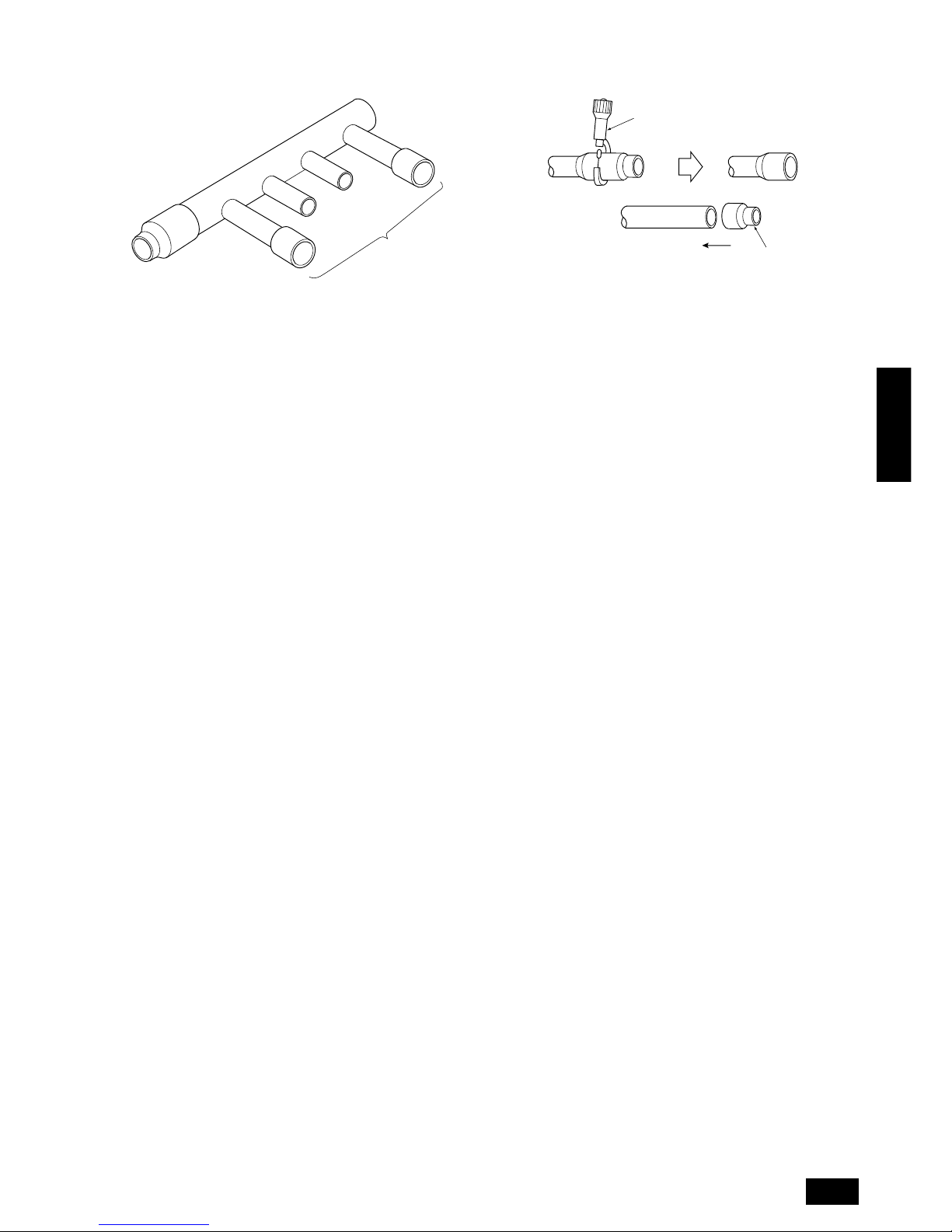
■ Header
A To outdoor unit
B To indoor unit
• No restriction is applied to the mounting posture of the header.
• If the diameter of the refrigerant piping selected using the proce-
dures described on pages 14 and the size of the joint is different,
match the sizes using a deformed joint. The deformed joint is included with the kit.
B
A
C Pipe cutter
D or
E Deformed joint
• When the number of pipes to be connected is smaller than the number
of header branches, install a cap to the unconnected branches. The
cap is included with the kit.
C
E
D
18
ENGLISH
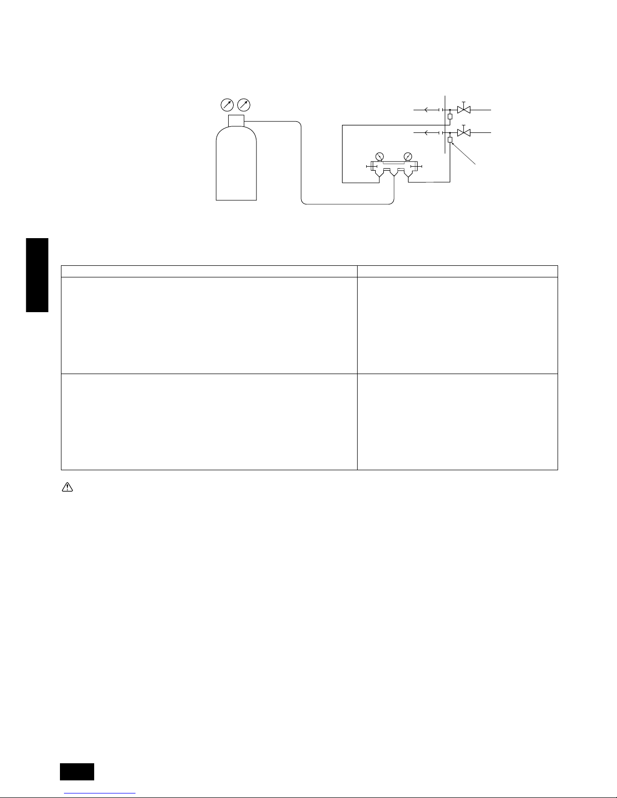
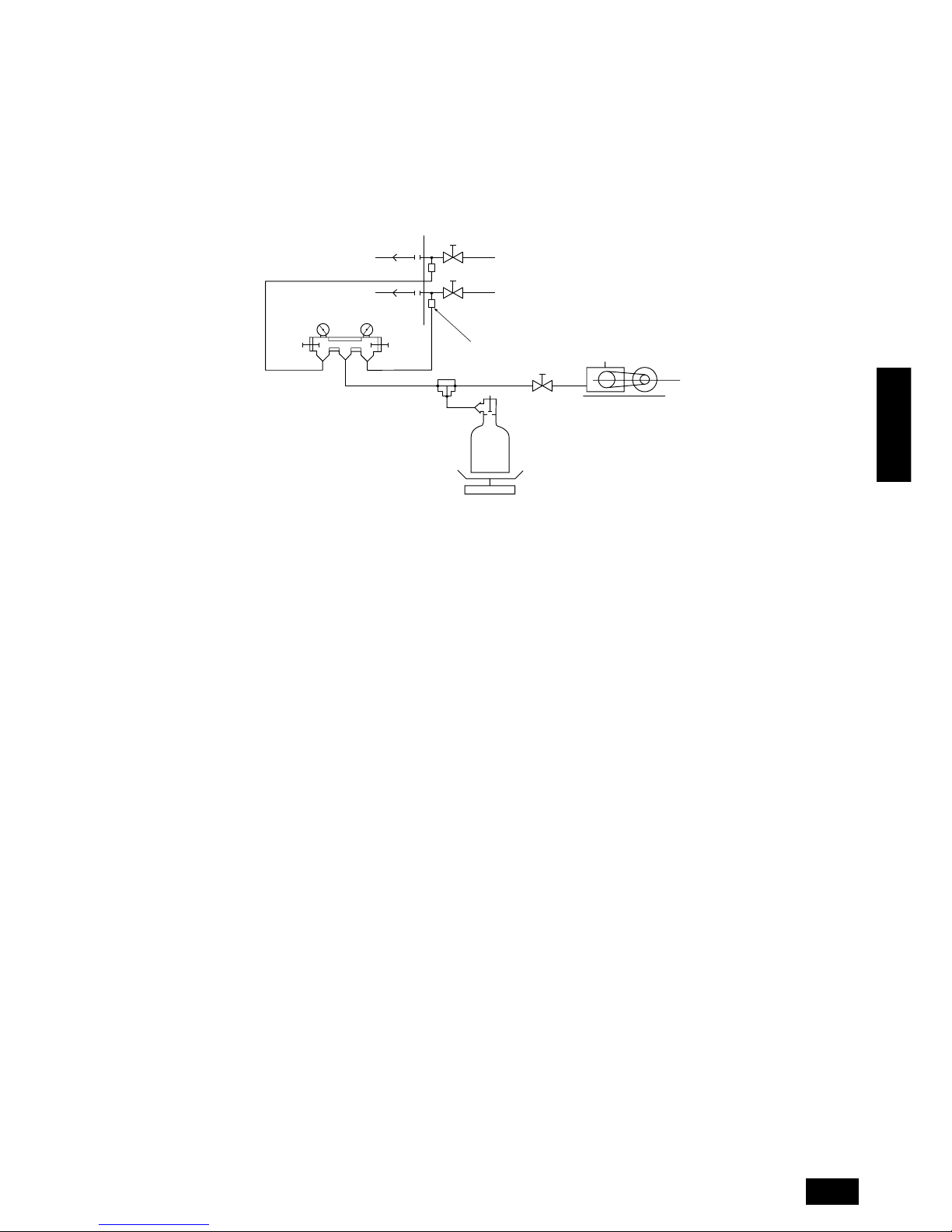
10.5. Airtight test and evacuation, refrigerant charging
1 Airtight test
Perform with the stop valv e of the outdoor unit closed, and pressurize the connection piping and the indoor unit from the service port provided on the
stop valve of the outdoor unit. (Always pressurize from both the liquid pipe and the gas pipe service ports.)
A Nitrogen gas
B To indoor unit
C System analyzer
D Lo Knob
E Hi Knob
F Ball valve
G Liquid pipe
H Gas pipe
I Outdoor unit
J Service port
The method of conducting the airtight test is basically the same as for older models. Howe ver, since the restrictions have a large affect on deterioration
of the refrigerator oil, always observe them. Also, with nonazeotropic refrigerant (R407C, etc.), gas leakage causes the composition to change and
affects performance. Therefore, since the entire amount must be replaced if gas leakage occurs, perform the airtightness test cautiously.
Restriction
• If a flammable gas or air (oxygen) is used as the pressurization gas, it may catch fire or explode.
• Do not use a refrigerant other than that indicated on the
unit.
• Sealing with gas from a cylinder will cause the composition of the refrigerant in the cylinder to change.
• Use a pressure gauge, charge box, and other parts especially for R407C.
• An electric leak detector for R22 cannot detect leaks.
• Do not use a haloid torch. (Leaks cannot be detected.)
Airtight test procedure
1.Nitrogen gas pressurization
(1) After pressurizing to the design pressure (2.98 MPa) using nitrogen gas, let stand
for about one day. If the pressure does not drop, airtightness is good.
However, if the pressure drops, since the leaking point is unknown, the following
bubble test may also be performed.
(2) After the pressurization described above, spra y the flare connection parts, brazed
parts, flanges, and other parts that may leak with a bubbling agent (Kyuboflex,
etc.) and visually check for bubbles.
(3) After the airtight test, wipe off the bubbling agent.
2.Pressurization using refrigerant gas and nitrogen gas
(1) After sealing with liquid R407C from a cylinder and pressurizing to a gas pressure
of approximately 0.2 MPa, pressurize to the design pressure (2.98 MPa) using
nitrogen gas.
However , do not pressurize at one time. Stop during pressurization and check that
the pressure does not drop.
(2) Check f or gas leaks by checking the flare connection parts, brazed parts, flanges,
and other parts which may leak using an R407C compatible electric leak detector.
(3) This test may be used together the with bubble type gas leak test.
D
C
C
B
E
F
G
H
I
J
A
LO
HI
Caution:
Do not use a refrigerant other than R407C.
- If a refrigerant (R22, etc,) other than R407C is used, the chlorine in the refrigerant will cause the refrigerator oil to deteriorate.
LO HI
19
ENGLISH
2 Evacuation
As shown in the figure below, evacuate with the stop valve of the outdoor unit closed and evacuate both the connection piping and the indoor unit
from the service port provided on the stop valve of the outdoor unit using a vacuum pump. (Alwa ys e v acuate from the service port of both the liquid
pipe and the gas pipe.) After the vacuum reaches 650 Pa, continue evacuation for at least one hour or more. Then, stop the vacuum pump and let
stand for one day and check if they vacuum does not rise. (If the vacuum rises, since water may be mixed in, pressurize up to 0.05 MPa using dry
nitrogen gas and evacuate again.)
Evacuate from the service port of the ball valve with a vacuum pump.
Finally, seal with liquid refrigerant from the liquid pipe. Moreover, during operation, adjust the refrigerant amount from the gas pipe so that the
refrigerant is always an appropriate amount.
* Never perform air purging using refrigerant.
A System analyzer
B Lo Knob
C Hi Knob
D Ball valve
E Liquid pipe
F Gas pipe
G Service port
H Three-way joint
I Valve
J Valve
K R407C cylinder
B
A
K
J
L
H
M
C
D
E
F
G
I
LO HI
L Scale
Use a graviometer. (One that can measure down to 0.1 kg.)
M Vacuum pump
Use a vacuum pump with a reverse flow check valve.
(Recommended vacuum gauge: ROBINAIR 14830A Thermistor Vacuum
Gauge)
Also use a vacuum gauge that reaches 65 Pa or greater after oper ating for
five minutes.
LO HI
20
ENGLISH
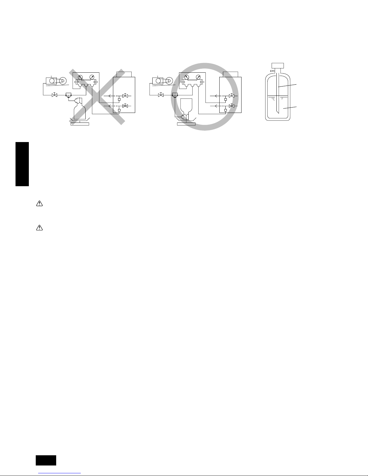
[When cylinder does not have a syphon pipe] [When cylinder has a syphon pipe
(Refrigerant can be charged with the
cylinder standing upright.)]
3 Refrigerant Charging
Since the refrigerant used with the unit is nonazerotropic, it must be charged in the liquid state. Consequently , when charging the unit with refrigerant
from a cylinder, if the cylinder does not have a syphon pipe , charge the liquid refrigerant by turning the cylinder upside-down as shown below. If the
cylinder has a syphon valve like that shown in the figure at the right, the liquid refrigerant can be charged with the cylinder standing upright.
Therefore, give careful attention to the cylinder specifications. If the unit should be charged with gas refrigerant, replace all the refrigerant with new
refrigerant. Do not use the refrigerant remaining in the cylinder.
A
A
B
C
A R407C cylinder
B Syphon pipe
C Liquid refr igerant
Note:
Always add an appropriate amount of refrigerant. (For the refrigerant additional charge, see pages 13 to 14.) Also always seal the system
with liquid refrigerant. Too much or too little refrigerant will cause trouble.
Use a gauge manifold, charging hose, and other parts for the refrigerant indicated on the unit.
Note that it is not possible to determine if a correct amount is being used with the accumulator level (AL).
Warning:
When installing or moving the unit, do not charge it with refrigerant other than the refrigerant (R407C) specified on the unit.
- Mixing of different refrigerant, air, etc. may cause the refrigerant cycle to malfunction and result in severe damage.
Caution:
• Use a vacuum pump with a reverse flow check valve.
- If the vacuum pump does not hav e a re v erse flow chec k v alv e, the vacuum pump oil may flow back into the refrigerant cycle and cause deteriora-
tion of the refrigerator oil and other trouble.
• Do not use a charging cylinder.
- Using a charging cylinder may cause the refrigerant to deteriorate.
• Do not use the tools shown below used with conventional refrigerant.
(Gauge manifold, charge hose, gas leak detector, check valve, refrigerant charge base, vacuum gauge, refrigerant recovery equipment)
- Mixing of conventional refrigerant and refrigerator oil may cause the refrigerator oil to deteriorate.
- Mixing of water will cause the refrigerator oil to deteriorate.
- R407C refrigerant does not contain any chlorine. Therefore, gas leak detectors for conventional refrigerants will not react to it.
• Manage the tools more carefully than normal.
- If dust, dirt, or water gets in the refrigerant cycle, the refrigerator oil will deteriorate.
21
ENGLISH
E
E
D
A
B
10.6. Thermal insulation of refrigerant
piping
Be sure to give insulation work to refrigerant piping by covering liquid
pipe and gas pipe separately with enough thickness heat-resistant
polyethylene, so that no gap is observed in the joint between indoor unit
and insulating material, and insulating materials themselves. When insulation work is insufficient, there is a possibility of condensation drip,
etc. Pay special attention to insulation work to ceiling plenum.
C
A
B
D
E
A Steel wire
B Piping
C Asphaltic oily mastic or asphalt
D Heat insulation material A
E Outer covering B
Heat
insulation
material A
Outer
covering B
Glass fiber + Steel wire
Adhesive + Heat - resistant polyethylene foam +
Adhesive tape
Indoor Vinyl tape
Floor exposed
Water-proof hemp cloth + Bronze asphalt
Outdoor
Water-proof hemp cloth + Zinc plate + Oily paint
Note:
When using polyethylene cover as covering material, asphalt roofing shall not be required.
A
• Do not insulate gas or low pressure pipe and liquid or high
pressure pipe together.
• Be sure to fully insulate connecting portion.
A Liquid pipe
B Gas pipe
C Electric wire
D Finishing tape
E Insulating material
A Liquid pipe
B Gas pipe
D Finishing tape
E Insulating material
Bad example
Good example
A These parts are not insulated.
B
A
D
C
E
Note:
No heat insulation must be provided for electric wires.
22
ENGLISH
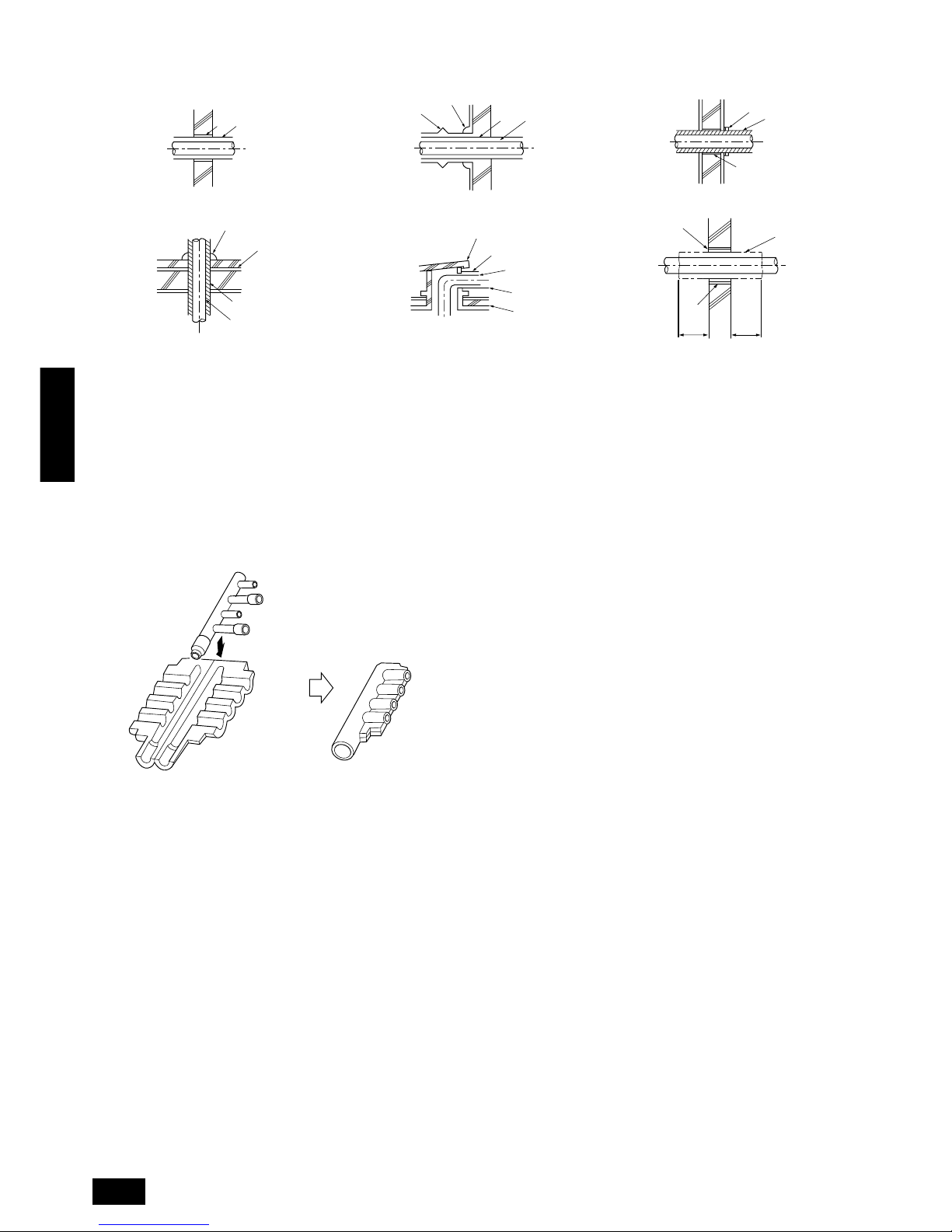
Penetrations
Inner wall (concealed) Outer wall Outer wall (exposed)
Floor (fireproofing) Roof pipe shaft Penetrating portion on fire limit and boundary wall
A Sleeve
B Heat insulating material
C Lagging
D Caulking material
E Band
F Waterproofing layer
G Sleeve with edge
H Lagging material
I Mortar or other incombustible caulking
J Incombustible heat insulation material
When filling a gap with mortar, cover the penetration part with steel plate
so that the insulation material will not be caved in. For this part, use
incombustible materials for both insulation and cov ering. (Vinyl cov ering
should not be used.)
Branch piping section
Insulate the header using
the insulation
material attached to the
branch pipe kit
as shown in the figure.
A B
A B
D
C
E
I
B
D
F
G
B
F
H
D
B
G
I
A
J
1m1m

23
ENGLISH
11. Electrical work
11.1. Caution
1 Follow ordinance of your governmental organization for technical standard related to electrical equipment, wiring regulations and guidance of each
electric power company.
Warning:
Be sure to have authorized electric engineers do electric work using special circuits in accordance with regulations and this installation
manual. If power supply circuit has a lack of capacity or electric work deficiency, if may cause an electric shock or fire.
2 Install the outdoor unit transmission line away from the power source wiring so that it is not affected by electric noise from the power source . (Do not
run it through the same conduit.)
3 Be sure to provide designated grounding work to outdoor unit.
Caution:
Be sure to put outdoor unit to earth. Do not connect earth line to any gas pipe, water pipe, lightning rod or telephone earth line. If earth is
incomplete, it may cause an electric shock.
4 Give some allowance to wiring for electrical part box of indoor and outdoor units, because the box is sometimes removed at the time of service work.
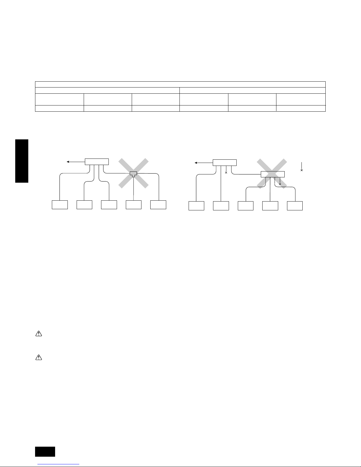
5 Never connect the main power source to terminal block of transmission line. If connected, electrical parts will be burnt out ( mark in the figure
below).
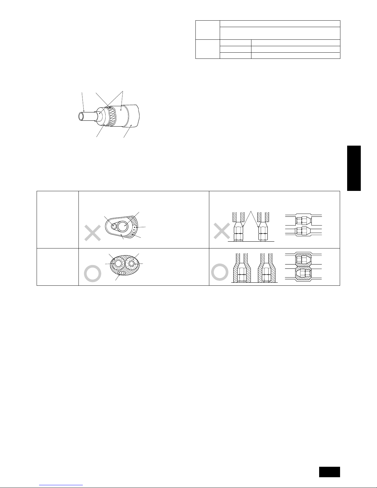
6 Use 2-core shield cable for transmission line. If tr ansmission lines of different systems are wired with the same multiplecore cable , the resultant poor
transmitting and receiving will cause erroneous operations (× mark in the figure below).
7 Only the transmission line specified should be connected to the terminal block for outdoor unit transmission.
(Transmission line to be connected with indoor unit : Terminal block TB3 for transmission line, Other : Terminal block TB7 for centralized control)
Erroneous connection does not allow the system to operate.
8 In case to connect with the upper class controller or to conduct group operation in different refrigerant systems, the control line for transmission is
required between the outdoor units each other.
Connect this control line between the terminal blocks for centralized control. (2-wire line with no polarity)
When conducting group operation in different refrigerant systems without connecting to the upper class controller, replace the insertion of the short
circuit connector from CN41 of one outdoor unit to CN40.
9 Group is set by operating the remote controller.
TB3
TB7
TB3
TB7
TB3
TB7
TB3
TB7
E
B
B
C
C
A
A
D
D
TB3: Transmission line terminal board, TB7: Central control line terminal board
A Outdoor unit
B 2-core cable
C Indoor unit
D Remote controller
E Multi-core cable
24
ENGLISH
11.2. Control box and connecting position of wiring
1 Outdoor unit
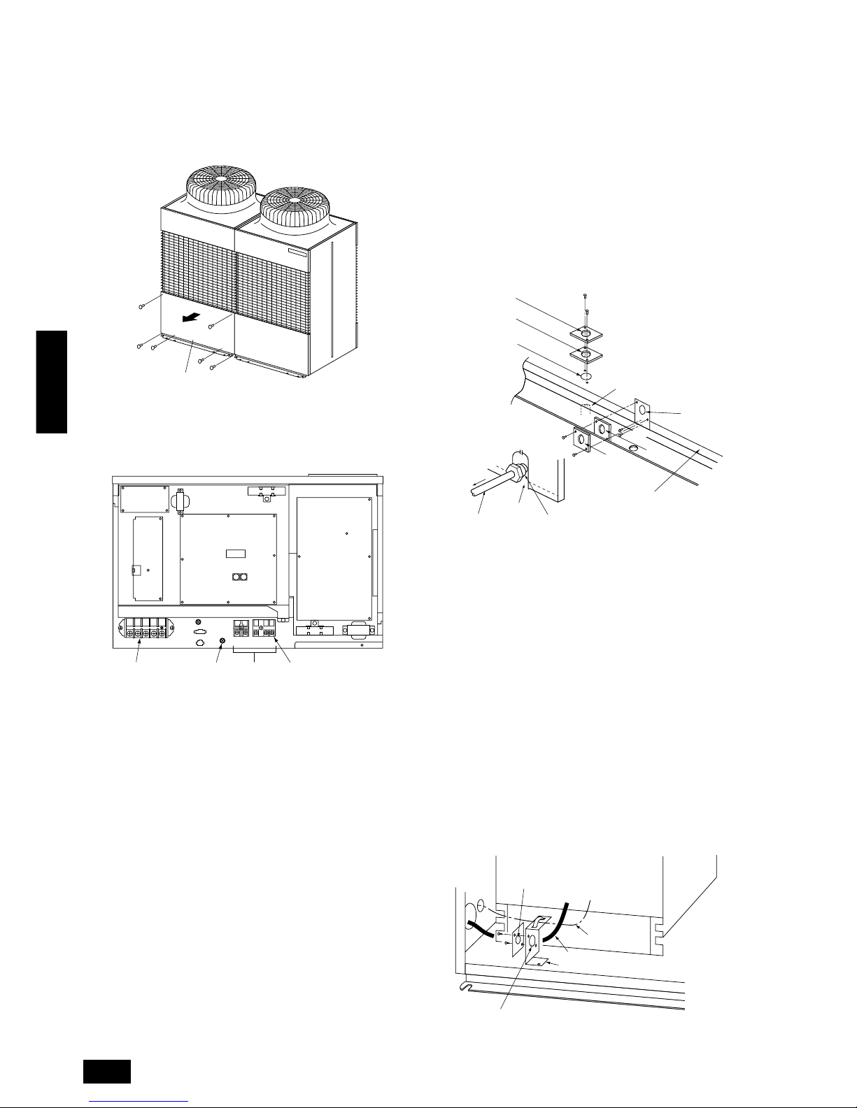
1. Remove the total of six screws at the top and bottom, and remove
the service panel by pulling it forward. (See the figure below.)
A Service panel
2. Remove the two screws on the left and right-hand of the base of the
control box and pull the overall co ver do wnwards to detach it. (A diagram with the control box cover removed is shown below.)
A INV board
B MAIN board
C Ten position
D One position
E Address switch
F FANCON board
G Power source
H Shield screw
I Transmission line
J RELAY board
K Shield terminal (S)
A
3. Connect indoor and outdoor units through the terminal block for transmission lines (TB3). Outdoor units and connections to central control
systems go through the terminal block for centralized control (TB7).
When making an indoor/outdoor connection with shielded wiring, connect the shield ground to the shield screw. When making a central
control system connection with shielded wiring, use the terminal block
for centralized control (TB7).
When the CN41 power supply connector of an outdoor unit has been
replaced with a CN40, the shield terminal (S) for centralized control
(TB7) should also be connected to the shield screw.
2 How to use the conduit mounting plate
(1) Conduit mounting plates (ø46, ø53, ø62) are being provided.
Select conduit mounting plate based on the outside diameter of conduit to be used and mount it as shown in the figure.
(2) Fix power source wiring to control box by using buffer bushing for
tensile force (PG connection or the like).
To prevent external tensile force from applying to the wiring connection
section of power source terminal block, use buffer bushing like PG
connection or the like.
knockout hole
T
e
n
s
i
l
e
f
o
r
c
e
A
D
A
F
G
E
B
C
B
A ø46 mounting hole
B ø53 mounting hole
C ø62 knockout hole
D For the connection of conduit at bottom
E ø62 mounting hole
F For the connection of conduit at front
G The front of outdoor unit
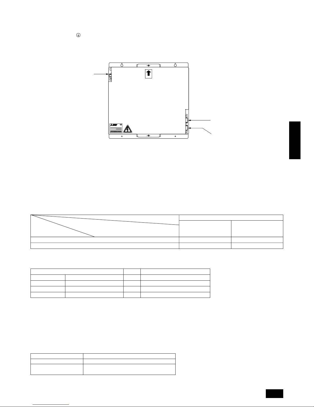
3 How to use the wire mounting plate
(1) When the power source and transmission lines are wired through
the knock-out hole of the left wiring, it is necessary to attach the
mounting plate onto the base of the front of the control box with two
screws.
In this case, please use the top clamp to fasten the transmission line
and the lower installation hole to fasten the power supply line.
If it does not match with the outer diameter of the power line conduit,
mount the power line conduit mounting plate (ø46) as shown in the fig-
ure below.
Also, please fasten it so that no tension is brought to bear on the power
line, as shown above.
Wire mounting plate
Ø46 mounting hole
Ø53 mounting hole
Control Box
Front side
Transmission
wire
Source wire
L1 L2 L3
TB1
TB7TB3
LD1
M1 M2M1 M2 S
N
F
J
B
CD A
E
GHI
K
Control Box
ø46 mounting hole
Transmission
wire
Source wire
Wire mounting plate
ø53 mounting hole
Front side
Tensile force
knockout hole
To prevent external tensile force from applying to the wiring connection
section of power source terminal block, use buffer bushing like PG
connection or the like.
25
ENGLISH
4 Transmission booster (optional)
(For details, see item 11.3. “Wiring transmission cables”)
Connect 220/230/240 VAC to L/N of power terminal block (TB1).
Connect the ground to the terminal of power terminal block (TB1).
Connect the outdoor unit side transmission cables to A/B of transmission cables terminal block 1 (TB2).
Connect the outdoor unit side shield to S of transmission cables terminal block 1 (TB2).
Connect additional indoor unit side transmission cables to A/B of transmission cables terminal block 2 (TB3).
Connect additional indoor unit side shield to S of transmission cables terminal block 2 (TB3).
OC
IC
RC
RP
Remote controller PAR-F 25MA
Prior to Ver. E After Ver. F
16 (32) 20 (40)
16 (32) 16 (32)
200 or lower
200 or higher
(*1)
Capability of the
connected indoor units
Remote controller type
Number of connected indoor units that can be
connected without a RP.
Name Code Possible unit connections
Outdoor unit
Indoor unit
Remote controller
Other
Outdoor unit controller
Indoor unit controller
Remote controller (*1)
Transmission booster unit
–
2 to 32 units per 1 OC (*1)
2 units maximum per group
0 to 1 unit per 1 OC (*1)
11.3. Wiring transmission cables
Wiring method, address setting method and permissible wiring length differ according to and whether or not you are using transmission booster. Chec k
permissible wiring length before wiring.
A may be required depending on the number of indoor units.
Item 4 “Wiring examples” gives typical wiring examples (A – C).
A. System using remote controller (1 outdoor unit)
B. System using remote controller (system operated as a group among multiple refrigerant systems)
C. System using power supply extension unit for transmission booster (combination of systems a – b)
1 Connecting a transmission booster
A transmission booster (RP) is required when the number of connected indoor unit models in a cooling system exceeds the number of models specified
in the chart below.
* The maximum number of units that can be controlled is determined by the indoor unit model, the type of remote controller and their capabilities.
The number of indoor units and the total number of remote controllers is displayed within the parenthesis ( ).
*1 If even one unit that is higher than 200 exists in the cooling system, the maximum capacity will be “200 or higher”.
2 Name, code and possible unit connections
*1 A transmission booster (RP) may be required depending on the number of connected indoor unit controllers.
3 Types of control cables
(1) Wiring transmission cables
• Types of transmission cables
Shielding wire CVVS or CPEVS
• Cable diameter
More than 1.25 mm
2
• Maximum wiring length within 200 m
(2) Remote control cables
Kind of remote control cable 2-core cable (unshielded)
Cable diameter 0.5 to 0.75 mm
2
Remarks
When 10 m is exceeded, use cable with the same
specifications as (1) Transmission line wiring.
4 Wiring examples
Typical wiring examples are shown on pages 26 to 30 (Wiring examples A – C).
PAC-SF46EPA
TRANSMISSION BOOSTER
3.4kg
220-240V:0.7A ~/N
WEIGHT
POWER RATING
MODEL
MADE IN JAPAN
50
UP
Transmission cables
Transmission cables
terminal block 2 (TB3)
terminal block 2 (TB3)
Transmission cables
Transmission cables
terminal block 1 (TB2)
terminal block 1 (TB2)
Power terminal
Power terminal
block (TB1)
block (TB1)
and Earth
and Earth
Power terminal
block (TB1)
and Earth
Transmission cables
terminal block 2 (TB3)
Transmission cables
terminal block 1 (TB2)
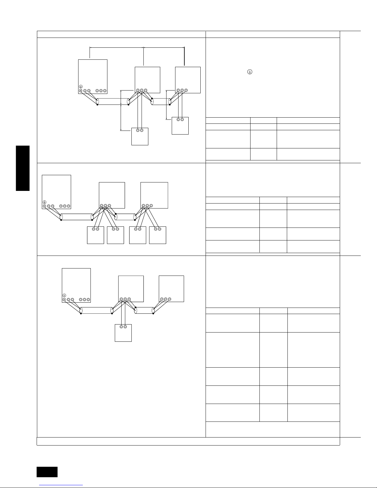
26
ENGLISH
Setting Method
—
Use the most recent
address of all the indoor
units plus 50
Indoor unit address plus
100
Unit
Indoor Unit
Outdoor Unit
Range
01 to 50
51 to 100
101 to 150
Remote Controller
Setting Method
Use the most recent address within the same group
of indoor units
Use an address, other than
that of the IC (Main) from
among the units within the
same group of indoor units
This must be in sequence
with the IC (Main)
Use the most recent address of all the indoor units
plus 50
Set at an IC (Main) address
within the same group plus
100
Set at an IC (Main) address
within the same group plus
150
Range
01 to 50
01 to 50
51 to 100
101 to 150
151 to 200
AB AB
M1
M2 M1 M2 S
OC
(51)
IC
M1 M2 S
TB5
(01)
IC
TB5
(02)
RC
TB6
(101)
RC
TB6
(151)
RC
TB6
(102)
RC
TB6
(152)
M1 M2 S
TB3 TB7
M1 M2
M1 M2 S
OC
IC
(51)
M1 M2 S
TB5
RC
RC
(01)
IC
M1 M2 S
TB5
(02)
L
1
L
3
r
1
r
2
L
2
TB6
(101)
TB6
(102)
TB3 TB7
Example of Wiring Control Cables Wiring Method and Address Setting
1. Standard Operation
• One remote controller for each indoor unit.
• Inside ( ) Address: There is no
need for setting the 100 position on
the remote controller.
2. Operation Using Two Remote controllers
3. Group Operation
• Using two remote
controllers for
each indoor unit.
• Operating multiple indoor units
using one remote controller.
a. Same as above
b. Same as above
c. Set the address switch as shown below.
* To set the outdoor unit address to 100, the outdoor address
setting switch must be set to 50.
a. Same as above
b. Connect terminals M1 and M2 on transmission cable terminal
block (TB5) of the IC main unit with the most recent address
within the same indoor unit (IC) group to terminal block (TB6)
on the remote controller.
c. Set the address setting switch as shown below.
* To set the outdoor unit address to 100, the outdoor address
setting switch must be set to 50.
a. Use feed wiring to connect terminals M1 and M2 on transmis-
sion cable block (TB3) for the outdoor unit (OC) to terminals
M1 and M2 on the transmission cable block (TB5) of each
indoor unit (IC). Use non-polarized two wire.
To ground the shielded wire, use cross-over wiring from the
ground terminal on the outdoor unit and terminal S on the
indoor unit (TB5).
b. Connect terminals M1 and M2 on the transmission cable block
(TB5) for each indoor unit with the terminal block (TB6) for the
remote controller (RC).
c. Set the address setting switch as shown below.
* To set the outdoor unit address to 100, the outdoor address
setting switch must be set to 50.
d. Use the indoor unit (IC) within the group with the most func-
tions as the IC (Main) unit.
A Main Remote
Controller
B Sub Remote
Controller
A Main
B Sub
A
B
M1 M2
M1 M2 S
OC
IC
(51)
M1 M2 S
TB5
RC
(01)
IC
M1 M2 S
TB5
(02)
TB6
(101)
TB3 TB7
Combinations of 1 through 3 above are possible.
Setting Method
—
Use the most recent
address of all the indoor
units plus 50
Indoor unit address plus
100
Indoor unit address plus
150
Range
01 to 50
51 to 100
101 to 150
151 to 200
Unit
Indoor Unit
Outdoor Unit
Main Remote Controller
Sub Remote Controller
Unit
IC (Main)
IC (Sub)
Outdoor Unit
Main Remote
Controller
Sub Remote
Controller
A. Example of a single-outdoor-unit system (Shielding wires and address setting are necessary)
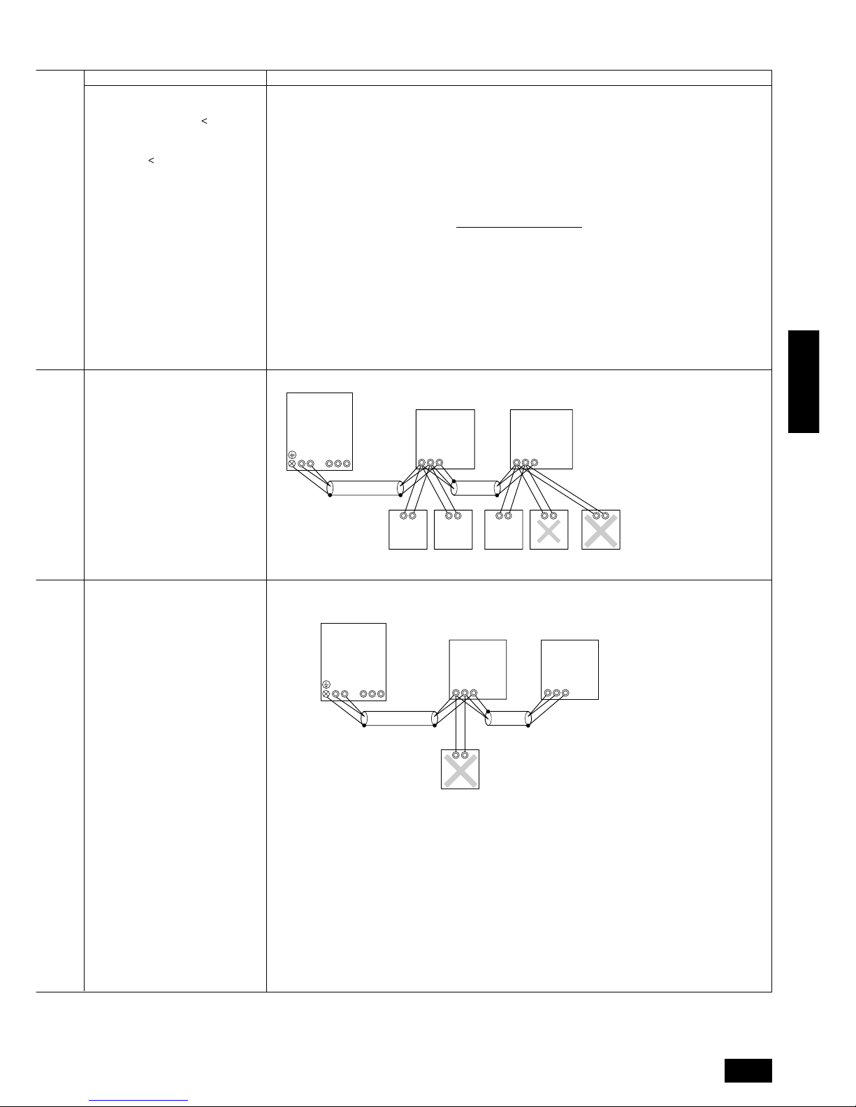
27
ENGLISH
Permissible Lengths Prohibited Items
Longest Transmission Cable Length
(1.25 mm2)
L1 + L2, L2 + L3, L3 + L1 = 200 m
Remote Controller Cable Length
1 If 0.5 to 0.75 mm
2
r1 , r2 = 10 m
2 If the length exceeds 10 m, the
exceeding section should be 1.25
mm2 and that section should be a
value within the total extension
length of the transmission cable
and maximum transmission cable
length (L3).
Same as above
Same as above
• Use the indoor unit
(IC) address plus 150
as the sub remote
controller address. In
this case, it is 152.
• Three or more remote
controllers (RC)
cannot be connected
to one indoor unit.
A Main
B Sub
• The remote controller address is the
indoor unit main
address plus 100. In
this case, it is 101.
A Main
B Sub
AB AB
M1
M2 M1 M2 S
OC
(51)
IC
M1 M2
SM1 M2
S
TB5
(01)
IC
TB5
(02)
RC
TB6
(101)
RC
TB6
(151)
RC
TB6
(102)
RC
TB6
(104)
RC
TB6
(103)
TB3 TB7
A
B
M1 M2
A B S
OC
IC
(51)
M1 M2 S
TB5
RC
(01)
IC
M1 M2 S
TB5
(02)
TB6
(102)
TB7TB3
Note:
1. If there is one or more 200 or higher indoor units within the same cooling system, and the number of indoor units exceeds 16 units, a
transmission booster is necessary (when a “PAR-F25MA Ver. F” or subsequent version of remote control is used).
2. If there is not even one 200 or higher indoor unit within the same cooling system, and the number of indoor units exceeds 20 units, a
transmission booster is necessary (when a “PAR-F25MA Ver. F” or subsequent version of remote control is used).
* For details, see wire connection example C.
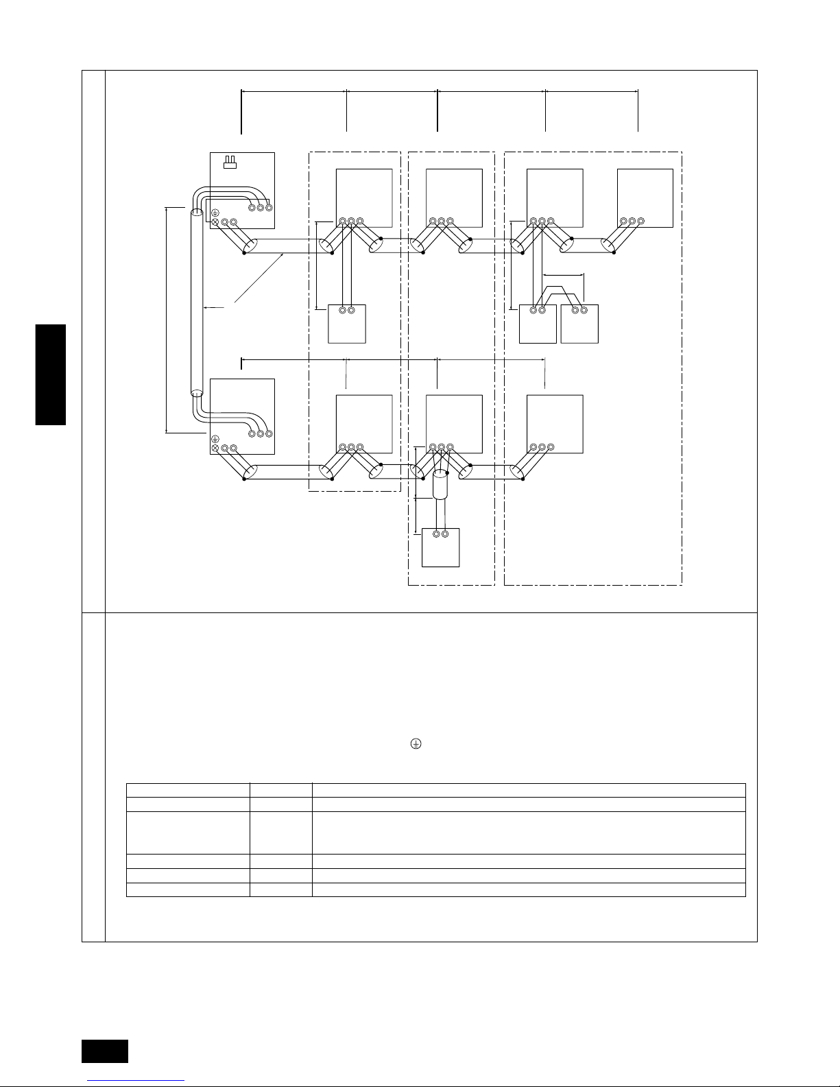
28
ENGLISH
h. The group setting operations among the multiple indoor units is done by the remote controller (RC) after the electrical power has been
turned on.
A B C
E
D
M1 M2
M1 M2 S
TB7
TB3
IC
(51)
M1 M2 S
TB5
RC
(01)
IC
M1 M2 S
TB5
(02)
IC
M1 M2 S
TB5
(04)
IC
M1 M2 S
TB5
(03)
IC
M1 M2 S
TB5
(05)
IC
M1 M2 S
TB5
(07)
IC
M1 M2 S
TB5
(06)
L1
L8
r1
r4
L9
L2 L3 L4
L5 L6 L7
TB6
(101)
RC
TB6
(105)
RC
TB6
(103)
RC
TB6
(155)
CN40
OC
M1 M2
M1 M2 S
TB7
TB3
(52)
OC
r2
r3
Example of transmission line wiring
A Group 1
B Group 3
C Group 5
D Shielded Wire
E Sub Remote Controller
( ) Address
Wiring method, address setting method
Unit Range Setting Method
IC (Main) 01 to 50 Use the most recent address within the same group of indoor units
IC (Sub) 01 to 50
Use an address, other than that of the IC (Main) from among the units within the same group of
indoor units
This must be in sequence with the IC (Main)
Outdoor Unit 51 to 100 Use the most recent address of all the indoor units plus 50
Main Remote Controller 101 to 150 Set at an IC (Main) address within the same group plus 100
Sub Remote Controller 151 to 200 Set at an IC (Main) address within the same group plus 150
B. Example of a group operation system with multiple outdoor units (Shielding wires and address setting are necessary)
a. Always use shielded wire when making connections between the outdoor unit (OC) and the indoor unit (IC), as well for all OC-OC, and IC-
IC wiring intervals.
b. Use feed wiring to connect terminals M1 and M2 and the ground terminal on the transmission cable terminal block (TB3) of each outdoor
unit (OC) to terminals M1, M2 and terminal S on the transmission cable block of the indoor unit (IC).
c. Connect terminals M1 and M2 on the transmission cable terminal block of the indoor unit (IC) that has the most recent address within the
same group to the terminal block (TB6) on the remote controller (RC).
d. Connect together terminals M1, M2 and terminal S on the terminal block for central control (TB7) for the outdoor unit (OC).
e. On one outdoor unit only, change the jumper connector on the control panel from CN41 to CN40.
f. Connect the terminal S on the terminal block for central control (TB7) for the outdoor unit (OC) f or the unit into which the jumper connector
was inserted into CN40 in Step above to the ground terminal
in the electrical component box.
g. Set the address setting switch as follows.
* To set the outdoor unit address to 100, the outdoor address setting switch must be set to 50.
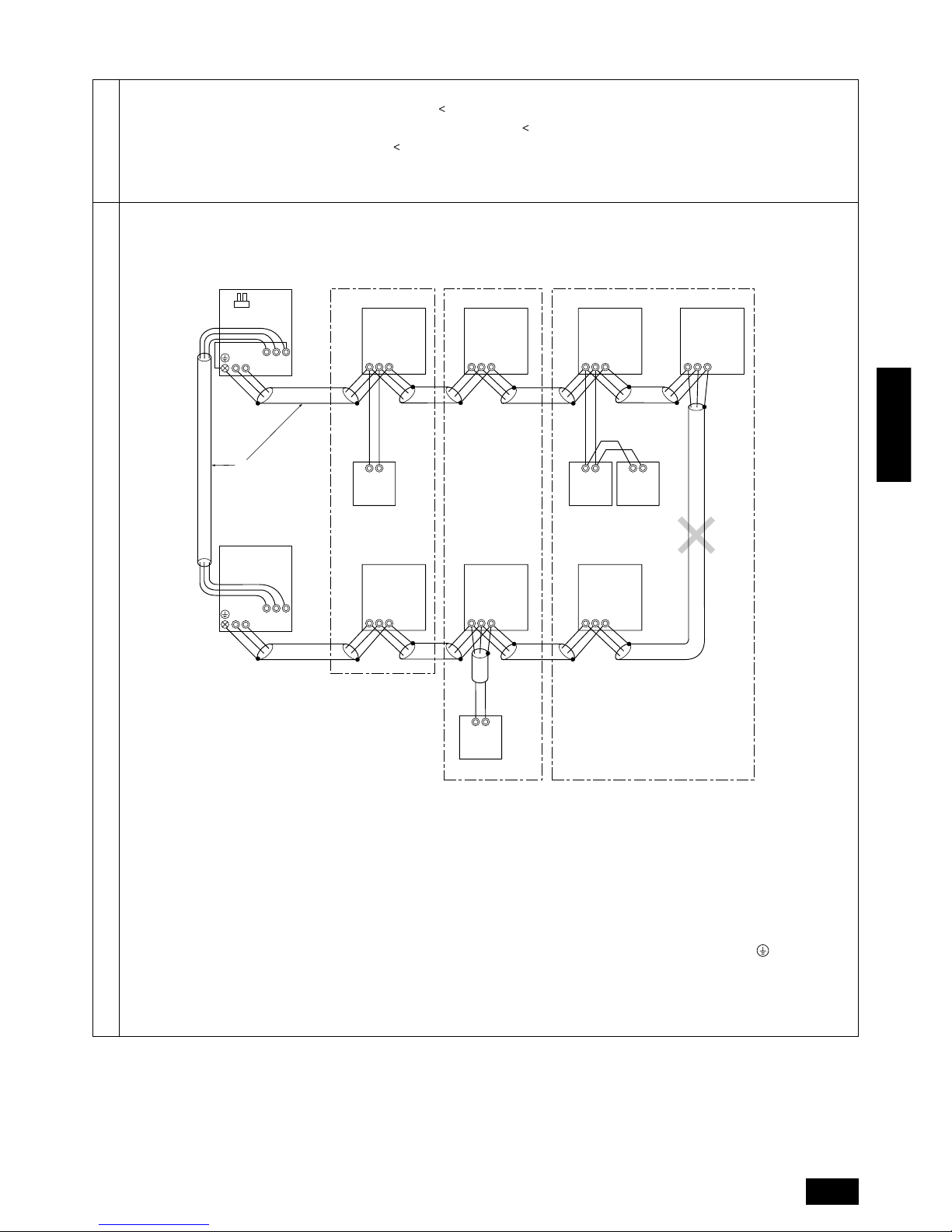
29
ENGLISH
A B C
E
D
M1 M2
M1 M2 S
TB7
TB3
IC
(51)
M1 M2 S
TB5
RC
(01)
IC
M1 M2 S
TB5
(02)
IC
M1 M2 S
TB5
(04)
IC
M1 M2 S
TB5
(03)
IC
M1 M2 S
TB5
(05)
IC
M1 M2 S
TB5
(07)
IC
M1 M2 S
TB5
(06)
TB6
(101)
RC
TB6
(105)
RC
TB6
(103)
RC
TB6
(155)
CN40
OC
M1 M2
SM1 M2
TB7
TB3
(52)
OC
Permissible Lengths
Prohibited Items
• Max length via outdoor units: L1+L2+L3+L4+L5+L6+L7+L9,
L
1+L2+L3+L4+L5+L6+L8+L9
=
500 m (1.25 mm2)
• Max transmission cable length: L1+L2+L3+L4, L5+L6+L7, L5+L6+L8, L7+L8 = 200 m (1.25 mm2)
• Remote controller wire length: r
1, r2, r3, r4
=
10 m (0.5 to 0.75 mm2)
If the length exceeds 10 m, use a 1.25 mm
2
shielded wire. The length of this section (L8) should be included
in the calculation of the maximum length and overall length.
A Group 1
B Group 3
C Group 5
D Shielded Wire
E Remote Controller
• The terminal S on the terminal block (TB7) for the central control panel should be connected to the ground terminal of the electric
components box of the only outdoor unit installed with the CN40 into which the jumper connector was inserted.
• Never connect together the terminal blocks (TB5) for tr ansmission wires for indoor units (IC) that hav e been connected to diff erent outdoor
units (OC).
• Set all addresses to ensure that they are not overlapped.
Note:
1. If there is one or more 200 or higher indoor units within the same cooling system, and the number of indoor units exceeds 16 units, a
transmission booster is necessary (when a “PAR-F25MA Ver. F” or subsequent version of remote control is used).
2. If there is not even one 200 or higher indoor unit within the same cooling system, and the number of indoor units exceeds 20 units, a
transmission booster is necessary (when a “PAR-F25MA Ver. F” or subsequent version of remote control is used).
* For details, see wire connection example C.
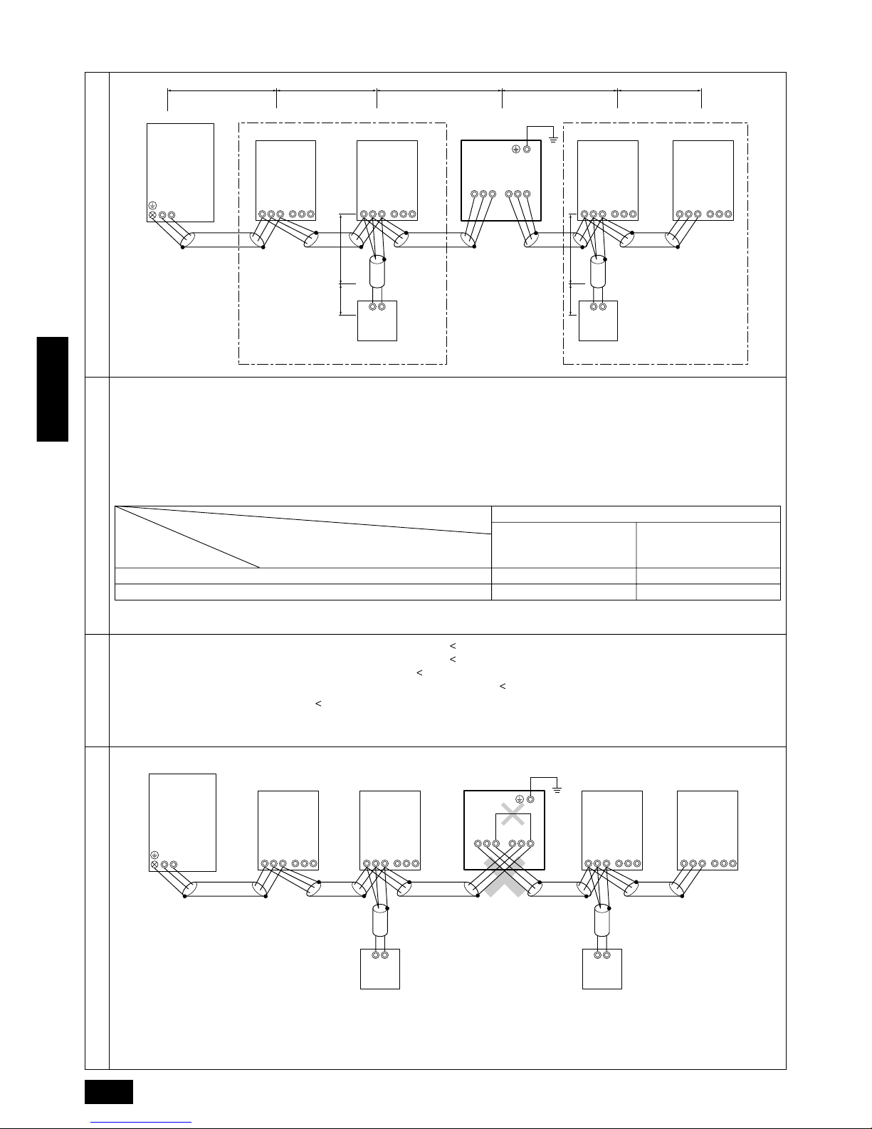
30
ENGLISH
• Indoor system maximum remote wiring length: 1 L1+L2+L3+L5+L6 = 200 m (1.25 mm2)
2 L1+L2+L3+L5+L7 = 200 m (1.25 mm2)
3 L1+L2+L4 = 200 m (1.25 mm2)
4 L6+L5+L3+L4, L4+L3+L5+L7 = 200 m (1.25 mm2)
• Remote control wiring length: r1, r2 = 10 m (0.5 to 0.75 mm2)
If the length exceeds 10 m, use 1.25 mm2 shielded cable and calculate the length of that portion (L4 and L7)
as within the total extended length and the longest remote length.
Example of transmission line wiring
200 or lower
200 or higher
Remote controller PAR-F 25MA
Prior to Ver. E After Ver. F
16 (32) 20 (40)
16 (32) 16 (32)
(*1)
Capability of the
connected indoor units
Remote controller type
Number of connected indoor units that can be
connected without a RP.
Permissible length
Prohibited items
Wiring method, address setting method
C. Example of a system using the transmission booster (Combination of systems A and B)
a. Address settings are the same as for wiring connection examples A and B.
b. Let the number of indoor units and remote control units connected be within the limit for the number of units shown in the following table for
the total of the number of units connected between the outdoor unit (OC) and the transmission booster (RP) N
1 and the number of units
connected after the transmission booster (RP) N2.
c. Connect the power supply ground to the transmission booster (RP) securely.
Connect the transmission lines of the outdoor unit side to terminals A and B of transmission line terminal block 1 (TB2) of the transmission
booster (RP).
Connect the transmission lines of the expansion indoor unit side to terminals A and B of the of transmission line terminal block 2 (TB3) of the
transmission booster (RP).
The number of indoor units and the total number of remote controllers is displayed within the parenthesis ( ).
*1 If even one unit that is higher than 200 exists in the cooling system, the maximum capacity will be “200 or higher”.
• Do not mistake the connection locations of transmission booster (RP) transmission line terminal block 1 (TB2) and transmission line
terminal block 2 (TB3). (Operation will not be normal in such a case.)
• Do not connect the S terminals of transmission line terminal block 1 (TB2) and transmission line terminal block 2 (TB3) of the transmission
booster (RP) together.
M1 M2
TB3
RC
N
1
N
2
IC
M1M2 S
TB5
IC
M1M2 S
TB5
123
TB13
123
TB13
RP
Ground
ABS
TB2
ABS
TB3
L
1
L
4
r
1
L
2
L
3
L
5
L
6
TB6
OC
L
7
r
1
RC
TB6
IC
M1M2 S
TB5
IC
M1M2 S
TB5
123
TB13
123
TB13
M1 M2
TB3
RC
IC
M1M2 S
TB5
IC
M1M2 S
TB5
123
TB13
123
TB13
RP
Ground
AB S
TB2
AB S
TB3
TB6
OC
RC
TB6
IC
M1M2 S
TB5
IC
M1M2 S
TB5
123
TB13
123
TB13
Ground
Ground
 Loading...