

Mitsubishi Electric CITY MULTI PQRY-P-YMF-C, CITY MULTI PQRY-P200YMF-C, CITY MULTI PQRY-P250YMF-C Installation Manual
Page 1

GB
D
F
I
NL
E
P
GR
RU
TR
Air-Conditioners For Building Application
HEAT SOURCE UNIT
PQRY-P-YMF-C
INSTALLATION MANUAL
For safe and correct use, please read this installation manual thoroughly before installing the air-conditioner unit.
INSTALLATIONSHANDB UCH
Zum sicheren und ordnungsgemäßen Gebrauch der Klimageräte das Installationshandbuch gründlich durchlesen.
MANUEL D’INSTALLATION
Veuillez lire le manuel d’installation en entier avant d’installer ce climatiseur pour éviter tout accident et vous assurer d’une utilisation correcte.
MANUAL DE INSTALACIÓN
Para un uso seguro y correcto, lea detalladamente este manual de instalación antes de montar la unidad de aire acondicionado.
MANUALE DI INSTALLAZIONE
Per un uso sicuro e corretto, leggere attentamente questo manuale di installazione prima di installare il condizionatore d’aria.
INSTALLATIEHANDLEIDING
Voor een veilig en juist gebruik moet u deze installatiehandleiding grondig doorlezen voordat u de airconditioner installeert.
MANUAL DE INSTALAÇÃO
Para segurança e utilização correctas, leia atentamente este manual de instalação antes de instalar a unidade de ar condicionado.
E°XEIPI¢IO O¢H°IøN E°KATA™TA™H™
°И· ·ЫК¿ПВИ· О·И ЫˆЫЩ‹ ¯Ъ‹ЫЛ, ·Ъ·О·ПВ›ЫЩВ ‰И·‚¿ЫВЩВ ЪФЫВ¯ЩИО¿ ·˘Щfi ЩФ ВБ¯ВИЪ›‰ИФ ВБО·Щ¿ЫЩ·ЫЛ˜ ЪИУ ·Ъ¯›ЫВЩВ ЩЛУ
ВБО·Щ¿ЫЩ·ЫЛ ЩЛ˜ МФУ¿‰·˜ ОПИМ·ЩИЫМФ‡.
РУКОВОДСТВО ПО УСТАНОВКЕ
Для осторожного и правильного использования прибора необходимо тщательно ознакомиться с данным руководством по
установке до выполнения установки кондиционера.
MONTAJ ELK‹TABI
Emniyetli ve do¤ru biçimde nas›l kullan›laca¤›n› ö¤renmek için lütfen klima cihaz›n› monte etmeden önce bu elkitab›n› dikkatle okuyunuz.
Page 2
2
4
[Fig. 4.0.1]
5
3 m
=
>
60°
=
<
3 m
=
>
B
A
C
1227
1177
500
392
61
D
E
A
B
C
D
600
500
400
1150
F
G
H
1150
400
400
E
H
G
F
E
D
C
B
A
TB8
3
A
B
4
63PW
[Fig. 5.1.1]
[Fig. 6.4.1]
6
[Fig. 6.1.1]
6.1
6.4
[Fig. 5.1.2]
[Fig. 5.2.1]
5.2
[Fig. 5.2.2]
A Heat source unit
B 4-ø14 (Anchoring hole)
C (Top view)
A Piping space (for left piping)
B Heat source unit
C Service space (front side)
D (Top view)
D Anti-vibration pad
E Concrete base
E Piping space (for top piping)
F Piping space (for left piping)
G Heat source unit
H (Front view)
A Water circulation pipe
B Close valve
C Close valve
D Water outlet
E Refrigerant piping
F Y-type strainer
G Water inlet
H Drain pipe
A Short-circuit wire (Connected before delivery from manufacturer)
B Pump interlock circuit connection
5.1
Page 3
3
7
7.2
[Fig. 8.2.2] [Fig. 8.2.3][Fig. 8.2.1]
B
A
K
J
L
H
M
C
D
E
F
G
I
LO HI
[Fig. 8.3.1]
[Fig. 8.3.3]
[Fig. 8.3.2]
8.3
8.2
L
M
1
3
a
A
b
c
d e
B
BB
A
BB
B
A (mm)
Å High press pipe ı Low press pipe
PQRY-P200 ø19.05 ø25.4
PQRY-P250 ø19.05 ø28.58
ø 19.05 (Flare)
ø 25.4 (Flange)
ø 28.58 (Frange)
B (mm)
Î Total capacity of indoor units ‰ Liquid line Ï Gas line
~ 80 ø9.52 ø15.88
81 ~ 160 ø9.52 ø19.05
a, b, c, d, e (mm)
Ì Model number ‰ Liquid line Ï Gas line
20,25,32,40 ø6.35 ø12.7
50,63,80 ø9.52 ø15.88
100,125,140 ø9.52 ø19.05
f, g, h, i, j
Ì Model number
‰ Liquid line Ï Gas line
fghi j
200 ø12.7 ø9.52 ø25.4 ø19.05 ø15.88
250 ø12.7 ø9.52 ø28.58 ø19.05 ø15.88
8
[Fig. 7.2.1]
A
C
j
i
g
f
h
A BC controller
B Indoor unit (20~140)
C Indoor unit (200, 250)
A Valve stem
B Stopper pin
C Packing (Accessory)
D Connecting pipe (Accessory)
E Open (Operate slowly)
F Cap, copper packing
G Service port
H Flare nut
I ø19.05
J ø25.4 (PQRY-P200)
ø28.58 (PQRY-P250)
K Field piping
L Close-packed packing
M Hollow packing
A System analyzer
B Lo Knob
C Hi Knob
D Ball valve
E Low press pipe
F High press pipe
G Service port
H Three-way joint
I Valve
J Valve
K Cylinder
L Scale
M Vacuum pump
A Nitrogen gas
B To indoor unit
C System analyzer
D Lo Knob
E Hi Knob
F Stop valve
G Low press pipe
H High press pipe
I Heat source unit
J Service port
Ç Connection of heat
sourse unit/BC controller
E
E
O
S
O
S
I
K
J
H
G
F
A
B
C
D
<A> [Ball valve (low press side)]
(This figure shows the valve in the fully open state.)
<B> [Ball valve (high press side)]
D
C
C
B
E
F
G
H
I
J
A
LO
HI
Page 4
4
9.4
9
8.4
[Fig. 8.4.4]
[Fig. 8.4.3]
[Fig. 8.4.2]
C
A
B
D
E
[Fig. 8.4.1]
[Fig. 9.4.1]
E E
D
A
E E
A
B
C
3 N~380 - 450 V
~220 - 240 V
[Fig. 9.2.1]
[Fig. 9.3.2]
B
A
D
C
E
E
E
D
A
B
D
F
G
B
<D> Floor (fireproofing)
E
I
B
<C> Outer wall (exposed)
A B
<A> Inner wall (concealed)
A B
D
C
<B> Outer wall
F
H
D
B
G
<E> Roof pipe shaft
I
A
J
1m1m
<F> Penetrating portion on
fire limit and boundary wall
9.3
9.2
[Fig. 9.3.1]
AB
L1 L2L3 N M1M2 M1M2 S
TB3 TB7
TB1
A
B
C
E
D
M1 M2
M1 M2 S
TB7
TB3
IC
(51)
M1 M2 S
TB5
RC
(01)
IC
M1 M2 S
TB5
(03)
IC
M1 M2 S
TB5
(02)
IC
M1 M2 S
TB5
(04)
IC
M1 M2 S
TB5
(05)
IC
M1 M2 S
TB5
(07)
IC
M1 M2 S
TB5
(06)
L
2
L
1
(101)
RC
(105)
RC
(104)
RC
(155)
OC
M1 M2
M1 M2 S
TB7
TB3
(53)
OC
r
3
BC
M1 M2 S
(52)
BC
M1 M2 S
(54)
M1M2S
Power Supply
Unit
M1M2S
MJ103
L
3
L
6
L
7
L
4
L
5
r
2
r
4
r
1
AB AB AB
AB
A
B
C
E
D
M1 M2
M1 M2 S
TB7
TB3
IC
(51)
M1 M2 1 2S
TB5 TB15
12
TB15
12
TB15
12
TB15
12
TB15
12
TB15
12
TB15
MA
(01)
IC
M1 M2 S
TB5
(03)
IC
M1 M2 S
TB5
(02)
IC
M1 M2 S
TB5
(04)
IC
M1 M2 S
TB5
(05)
IC
M1 M2 S
TB5
(07)
IC
M1 M2 S
TB5
(06)
L
2
L
1
MAMAMA
OC
M1 M2
M1 M2 S
TB7
TB3
(53)
OC
c
1
c
4
c
3
BC
M1 M2 S
(52)
BC
M1 M2 S
(54)
S
Power Supply
Unit
S
MJ103
L
3
L
6
L
7
L
4
c
3
ABABAB
M1M2
M1M2
c
1
c
1
c
2
c
2
AB
A Steel wire B Piping
C Asphaltic oily mastic or asphalt
D Heat insulation material A
E Outer covering B
A Liquid pipe B Gas pipe
C Electric wire D Finishing tape
E Insulater
A Sleeve B Heat insulating material
C Lagging D Caulking material
E Band F Waterproofing laye
G Sleeve with edge H Lagging material
I Mortar or other incombustible caulking
J Incombustible heat insulation material
A Power source
B Transmission line
A Group 1
B Group 3
C Group 5
D Shielded Wire
E Sub Remote
Controller
( ) Address
A Switch (Breakers for Wiring and Current Leakage)
B Heat source unit C BC Controller
D Pull Box E Indoor Unit
Page 5

5
GB
D
F
INL
E
PGRRUTR
Contents
1. Safety precautions
1.1. Before installation and electric work
s Before installing the unit, make sure y ou read all the “Safety
precautions”.
s The “Safety precautions” provide very important points re-
garding safety. Make sure you follow them.
Symbols used in the text
Warning:
Describes precautions that should be observed to prevent danger of injury
or death to the user.
Caution:
Describes precautions that should be observed to prevent damage to the
unit.
Symbols used in the illustrations
: Indicates an action that must be avoided.
: Indicates that important instructions must be followed.
: Indicates a part which must be grounded.
: Beware of electric shock. (This symbol is displa y ed on the main unit label.)
<Color: yellow>
Warning:
Carefully read the labels affixed to the main unit.
Warning:
• Ask the dealer or an authorized technician to install the air conditioner.
- Improper installation by the user may result in water leakage, electric shock,
or fire.
• Install the unit at a place that can withstand its weight.
- Inadequate strength may cause the unit to fall down, resulting in injuries.
• Use the specified cables for wiring. Make the connections securely so
that the outside force of the cable is not applied to the terminals.
- Inadequate connection and fastening may generate heat and cause a fire.
• Prepare for rain and other moisture and earthquakes and install the unit
at the specified place.
- Improper installation may cause the unit to topple and result in injury.
• Always use an filter and other accessories specified by Mitsubishi Electric.
- Ask an authorized technician to install the accessories. Improper installation
by the user may result in water leakage, electric shock, or fire.
• Never repair the unit. If the air conditioner must be repaired, consult the
dealer.
- If the unit is repaired improper ly, water leakage, electric shock, or fire may
result.
• If refrigerant gas leaks during installation work, ventilate the room.
- If the refr igerant gas comes into contact with a flame, poisonous gases will
be released.
• Install the air conditioner according to this Installation Manual.
- If the unit is installed improper ly, water leakage, electric shock, or fire may
result.
• Have all electric work done by a licensed electrician according to “Electric Facility Engineering Standard” and “Interior Wire Regulations”and
the instructions given in this manual and always use a special circuit.
- If the power source capacity is inadequate or electric work is performed im-
properly, electric shock and fire may result.
• Securely install the heat source unit terminal cover (panel).
- If the terminal cover (panel) is not installed properly , dust or w ater ma y enter
the heat source unit and fire or electric shock may result.
• When installing and moving the air conditioner to another site, do not
charge the it with a refrigerant different from the refrigerant (R407C) specified on the unit.
- If a different refrigerant or air is mixed with the original refrigerant, the refrig-
erant cycle may malfunction and the unit may be damaged.
• If the air conditioner is installed in a small room, measures must be taken
to prevent the refrigerant concentration from exceeding the safety limit
even if the refrigerant should leak.
- Consult the dealer regarding the appropriate measures to prevent the saf ety
limit from being exceeded. Should the refrigerant leak and cause the safety
limit to be exceeded, hazards due to lack of oxygen in the room could result.
• When moving and reinstalling the air conditioner, consult the dealer or
an authorized technician.
- If the air conditioner is installed improperly, water leakage, electric shock, or
fire may result.
• After completing installation work, make sure that refrigerant gas is not
leaking.
- If the refrigerant gas leaks and is exposed to a fan heater, stove, oven, or
other heat source, it may generate noxious gases.
• Do not reconstruct or change the settings of the protection devices.
- If the pressure switch, thermal switch, or other protection device is shorted
and operated forcibly, or parts other than those specified by Mitsubishi Electric are used, fire or explosion may result.
• To dispose of this product, consult your dealer.
• The installer and system specialist shall secure safety against leakage
according to local regulation or standards.
- Following standards may be applicable if local regulation are not available.
• Pay a special attention to the place, such as a basement, etc. where refrigeration gas can stay, since refrigeration is heavier than the air.
1.2. Precautions for devices that use R407C
refrigerant
Caution:
• Do not use the existing refrigerant piping.
- The old refrigerant and refrigerator oil in the existing piping contains a large
amount of chlorine which may cause the refrigerator oil of the new unit to
deteriorate.
• Use refrigerant piping made of phosphorus deoxidized copper and copper alloy seamless pipes and tubes. In addition, be sure that the inner
and outer surfaces of the pipes are clean and free of hazardous sulphur ,
oxides, dust/dirt, shaving particles, oils, moisture, or any other contaminant.
- Contaminants on the inside of the refrigerant piping may cause the refriger-
ant residual oil to deteriorate.
• Store the piping to be used during installation indoors and keep both
ends of the piping sealed until just before brazing. (Store elbows and
other joints in a plastic bag.)
- If dust, dirt, or water enters the refrigerant cycle, deterioration of the oil and
compressor trouble may result.
• Use ester oil, ether oil or alkylbenzene (small amount) as the refrigerator
oil to coat flares and flange connections.
- The refr igerator oil will degrade if it is mixed with a large amount of mineral
oil.
• Use liquid refrigerant to fill the system.
- If gas refrigerant is used to seal the system, the composition of the refriger-
ant in the cylinder will change and performance may drop.
1. Safety precautions ...................................................................................... 5
1.1. Before installation and electric work.......................................... 5
1.2. Precautions for devices that use R407C refrigerant.................. 5
1.3. Before getting installed.............................................................. 6
1.4. Before getting installed (moved) - electrical work...................... 6
1.5. Before starting the test run ........................................................ 6
2. Specifications.............................................................................................. 6
3. Confirmation of parts attached ................................................................... 6
4. Lifting method and weight of product .......................................................... 7
5. Installation of unit and service space .......................................................... 7
5.1. Installation ................................................................................. 7
5.2. Service space............................................................................ 7
6. Water pipe installation................................................................................. 7
6.1. Precautions during installation .................................................. 7
6.2. Insulation installation ................................................................. 7
6.3. Water processing and water quality control............................... 7
6.4. Pump interlock........................................................................... 8
7. Refrigerant piping installation ..................................................................... 8
7.1. Caution ...................................................................................... 8
7.2. Refrigerant piping system.......................................................... 8
8. Additional refrigerant charge....................................................................... 8
8.1. Calculation of Additional Refrigerant Charge ............................ 8
8.2. Caution for piping connection/valve operation........................... 9
8.3. Airtight test, evacuation, and refrigerant charging..................... 9
8.4. Thermal insulation of refrigerant piping ................................... 10
9. Wiring........................................................................................................ 11
9.1. Caution .................................................................................... 11
9.2. Control box and connecting position of wiring......................... 11
9.3. Wiring transmission cables...................................................... 11
9.4. Wiring of main power supply and equipment capacity ............ 12
10. Test run ..................................................................................................... 12
10.1. The following phenomena do not represent trouble
(emergency) ............................................................................ 12
Page 6

6
GB
D
F
INL
E
PGRRUTR
• Install an leak circuit breaker, as required.
- If an leak circuit breaker is not installed, electric shock may result.
• Use power line cables of sufficient current carrying capacity and rating.
- Cables that are too small may leak, generate heat, and cause a fire.
• Use only a circuit breaker and fuse of the specified capacity.
- A fuse or circuit breaker of a larger capacity or a steel or copper wire may
result in a general unit failure or fire.
• Do not wash the air conditioner units.
- Washing them may cause an electric shock.
• Be careful that the installation base is not damaged by long use.
- If the damage is left uncorrected, the unit may fall and cause personal injury
or property damage.
• Install the drain piping according to this Installation Manual to ensure
proper drainage. Wrap thermal insulation around the pipes to prevent
condensation.
- Improper drain piping may cause water leakage and damage to furniture
and other possessions.
• Be very careful about product transportation.
- Only one person should not carry the product if it weighs more than 20 kg.
- Some products use PP bands for packaging. Do not use any PP bands for a
means of transportation. It is dangerous.
- When transporting the heat source unit, etc., by the hanger bolts, support it
at four points. If it is supported at three points or less, it will become unstable
when set down and may fall.
• Safely dispose of the packing materials.
- Packing materials, such as nails and other metal or wooden parts, may cause
stabs or other injuries.
- Tear apart and throw away plastic packaging bags so that children will not
play with them. If children play with a plastic bag which was not torn apart,
they face the risk of suffocation.
1.5. Before starting the test run
Caution:
• Turn on the power at least 12 hours before starting operation.
- Star ting operation immediately after turning on the main power switch can
result in severe damage to internal parts. Keep the power switch turned on
during the operational season.
• Do not touch the switches with wet fingers.
- Touching a switch with wet fingers can cause electric shock.
• Do not touch the refrigerant pipes during and immediately after operation.
- During and immediately after operation, the refrigerant pipes are may be hot
and may be cold, depending on the condition of the refrigerant flowing through
the refrigerant piping, compressor, and other refrigerant cycle parts. Your
hands may suffer burns or frostbite if you touch the refrigerant pipes.
• Do not operate the air conditioner with the panels and guards removed.
- Rotating, hot, or high-voltage parts can cause injuries.
• Do not turn off the power immediately after stopping operation.
- Always wait at least five minutes before turning off the power. Otherwise,
water leakage and trouble may occur.
• Do not touch the surface of the compressor during servicing.
- If unit is connected to the supply and not running, crank case heater at
compressor is operating.
• Do not use a refrigerant other than R407C.
- If another refrigerant (R22, etc.) is used, the chlorine in the refr igerant may
cause the refrigerator oil to deteriorate.
• Use a vacuum pump with a reverse flow check valve.
- The vacuum pump oil may flow back into the refrigerant cycle and cause the
refrigerator oil to deteriorate.
• Do not use the following tools that are used with conventional refrigerants.
(Gauge manifold, charge hose, gas leak detector , reverse flow c heck valve,
refrigerant charge base, refrigerant recovery equipment)
- If the conventional refrigerant and refrigerator oil are mixed in the R407C,
the refrigerant may deteriorated.
- If water is mixed in the R407C, the refrigerator oil may deteriorate.
- Since R407C does not contain any chlorine, gas leak detectors for conven-
tional refrigerants will not react to it.
• Do not use a charging cylinder.
- Using a charging cylinder may cause the refrigerant to deteriorate.
• Be especially careful when managing the tools.
- If dust, dirt, or water gets in the refrigerant cycle, the refrigerant may deterio-
rate.
1.3. Before getting installed
Caution:
• Do not install the unit where combustible gas may leak.
- If the gas leaks and accumulates around the unit, an explosion may result.
• Do not use the air conditioner where food, pets, plants, precision instruments, or artwork are kept.
- The quality of the food, etc. may deteriorate.
• Do not use the air conditioner in special environments.
- Oil, steam, sulfuric smoke, etc. can significantly reduce the performance of
the air conditioner or damage its parts.
• When installing the unit in a hospital, communication station, or similar
place, provide sufficient protection against noise.
- The inverter equipment, private power generator, high-frequency medical
equipment, or radio communication equipment may cause the air conditioner
to operate erroneously, or fail to operate. On the other hand, the air conditioner may affect such equipment by creating noise that disturbs medical
treatment or image broadcasting.
• Do not install the unit on a structure that may cause leakage.
- When the room humidity exceeds 80 % or when the drain pipe is clogged,
condensation may drip from the indoor unit. P erform collective drainage w ork
together with the heat source unit, as required.
1.4. Before getting installed (moved) - elec-
trical work
Caution:
• Ground the unit.
- Do not connect the ground wire to gas or water pipes, lightning rods, or
telephone ground lines. Improper grounding may result in electric shock.
• The reverse phase of L lines (L
1, L2, L3) can be detected (Error cord: 4103),
but the reverse phase of L lines and N line can be not be detected.
- The some electric parts should be damaged when power is supplied under
the miss wiring.
• Install the power cable so that tension is not applied to the cable.
- Tension may cause the cable to break and generate heat and cause a fire.
3. Confirmation of parts attached
2. Specifications
1 Hanger bolts M12 × 4 2 Wiring mounting board × 1 3 Tapping screw M4 × 2
4 Connecting pipe × 1 (Connecting pipe is fixed with the unit.) 5 Packing (inside ø23, outside ø35) × 1
6 Bushing × 2
Model
Noise level
Net weight
Maximum refrigerant pressure
Indoor units
Total capacity
Model / Quantity
Operation temperature
PQRY-P200YMF-C PQRY-P250YMF-C
51 dB <A> 52 dB <A>
270 kg 280 kg
2.94 MPa
50 ~ 150 %
20 ~ 200 / 1 ~ 15 20 ~ 250 / 1 ~ 16
Water temperature: 10˚C ~ 45˚C Note.1
Note 1. When the total capacity of indoor units exceeds 130% of heat source units capacity, the operating temperature range of circulating water is 15˚C ~ 45˚C
Page 7

7
GB
D
F
INL
E
PGRRUTR
5. Installation of unit and service space
5.1. Installation
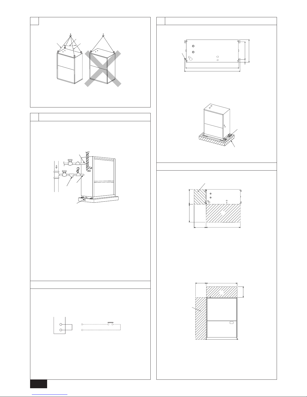
• Using the anchoring holes shown below, firmly bolt the unit to the base.
[Fig. 5.1.1] (P.2)
A Heat source unit B 4-ø14 (Anchoring hole) C (Top view)
Bases and anti-vibration
• Be sure to install unit in a place strong enough to withstand its weight. If the
base is unstable, reinforce with a concrete base.
• The unit must be anchored on a level surface. Use a level to check after
installation.
• Anti-vibration pads must be placed under the base of the unit.
• If the unit is installed near a room where noise is a problem, using an anti-
vibration stand on the base of the unit is recommended.
[Fig. 5.1.2] (P.2)
D Anti-vibration pad E Concrete base
Warning:
• Be sure to install unit in a place strong enough to withstand its weight.
Any lack of strength may cause unit to fall down, resulting in a personal
injury.
• Have installation work in order to protect against earthquake.
Any installation deficiency may cause unit to fall down, resulting in a
personal injury.
5.2. Service space
• Please allow for the following service spaces after installation.
(All servicing can be performed from the front of the unit)
[Fig. 5.2.1] (P.2)
A Piping space (for left piping) B Heat source unit
C Service space (front side) D (Top view)
[Fig. 5.2.2] (P.2)
E Piping space (for top piping) F Piping space (for left piping)
G Heat source unit H (Front view)
4. Lifting method and weight of product
[Fig. 4.0.1] (P.2)
Caution:
Be very careful to carry product.
- Do not have only one person to carry product if it is more than 20 kg.
- PP bands are used to pack some products. Do not use them as a mean for transportation because they are dangerous.
- Tear plastic packaging bag and scrap it so that children cannot play with it. Otherwise plastic packaging bag may suffocate children to death.
- When transporting the heat source unit, etc., by the hanger bolts, support it at four points. If it is supported at three points or less, it will become unstable when set down
and may fall.
6. Water pipe installation
• City Multi WR2 Series pipes are similar to other air-conditioning pipes, how-
ever, please observe the following precautions during installation.
6.1. Precautions during installation
• Use the reverse-return method to insure proper pipe resistance to each unit.
• To insure easy maintenance, inspection, and replacement of the unit, use a
proper joint, valve, etc. on the water intake and outlet port. In addition, be sure
to install a strainer on the water intake pipe. (In order to maintain the heat
source unit, a strainer on the circulating water inlet is necessary.)
* An example of the heat source unit installation is shown in the diagram below .
• Install a suitable air vent on the water pipe. After sending water through the
pipe, be sure to vent the excess air.
• Compressed water may form in the low-temperature sections of heat source
unit. Use a drainage pipe connected to the drain v alve at the base of the unit to
drain the water.
• There is a water vent plug in the center of the heat exchanger water inlet head
at the middle of the unit. Use this for maintenance, etc.
In addition, do not allow any of the unit’s electrical parts (such as the solenoid
valve coil or compressor power supply) to become wet.
• Install a back flow-prevention valve on the pump and a flexible joint to prevent
excess vibration.
• Use a sleeve to protect the pipes where they go through a wall.
• Use metal fittings to secure the pipes, and install them so that they have
maximum protection against breakage and bending.
• Do not confuse the water intake and outlet valves.
• This unit doesn’t have any heater to prevent freezing within tubes. When the
water flow is stopped on low ambient, take out the water from tubes.
• The unused knockout holes should be closed and the opening of refrigerant
pipes, water pipes, power source and transmission wires should be filled with
putty and so on to prevent from rain. (field construction)
Example of heat source unit installation (using left piping)
[Fig. 6.1.1] (P.2)
A Water circulation pipe B Close valve
C Close valve D Water outlet
E Refrigerant piping F Y-type strainer
G Water inlet H Drain pipe
6.2. Insulation installation
With City Multi WR2 Series piping, as long as the temperature range of the circulating water is kept to average temper atures year-round (30°C in the summer , 20°C
in the winter), there is no need to insulate or otherwise protect indoor piping from
exposure. You should use insulation in the following situations:
• Any heat source piping.
• Indoor piping in cold-weather regions where frozen pipes are a problem.
• When air coming from the outside causes condensation to form on piping.
• Any drainage piping.
6.3. Water pr ocessing and water quality control
T o preserve w ater quality, use the closed type of cooling tower f or WR2. When the
circulating water quality is poor, the water heat exchanger can develop scales,
leading to a reduction in heat-exchange power and possible corrosion of the heat
exchanger. Please pay careful attention to w ater processing and water quality control
when installing the water circulation system.
• Removal of foreign objects or impurities within the pipes.
During installation, be careful that foreign objects, such as welding fragments,
sealant particles, or rust, do not enter the pipes.
• Water Quality Processing
1 Depending on the quality of the cold-temperature water used in the air-
conditioner, the copper piping of the heat exchanger ma y become corroded.
We recommend regular water quality processing.
Cold water circulation systems using open heat storage tanks are
particularly prone to corrosion.
2 Water quality standard
Note. 2 It is clearly found that the component of the reference items will be
hazardous, however , the quantitativ e relationship between the content
and hazard has not been clarified yet. Theref ore , they are listed as the
reference items.
Standard items
Reference items
Note. 2
PH (25˚C)
Electric conductivity (25˚C) (µ s/cm)
Chlorine ion Cl
-
(mg/l)
Sulfate ion SO4
2-
(mg/l)
M-alkalinity CaCO
3
(mg/l)
Total hardness CaCO
3
(mg/l)
Iron Fe (mg/l)
Sulfur ion S
2-
(mg/l)
Ammonium ion NH
4+
(mg/l)
Silica SiO
2
(mg/l)
Items Standard values
7.0 ~ 8.0
300 or less
50 or less
50 or less
50 or less
70 or less
1.0 or less
Not be detected
Not be detected
30 or less
Page 8

8
GB
D
F
INL
E
PGRRUTR
8. Additional refrigerant charge
7. Refrigerant piping installation
A Always use a non-oxidizing brazing material for brazing the parts. If a non-
oxidizing brazing material is not used, it could cause clogging or damage to
the compressor unit.
B Never perform heat source unit piping connection work when it is raining.
Warning:
When installing and moving the unit, do not charge it with refrigerant other
than the refrigerant specified on the unit.
- Mixing of a different refrigerant, air, etc. may cause the refrigerant cycle to malfunction and result in severe damage.
Caution:
• Use a vacuum pump with a reverse flow check valve. (For R407C models)
- If the vacuum pump does not have a reverse flow check valve, the vacuum
pump oil may flow back into the refrigerant cycle and cause deterioration of
the refrigerator oil and other trouble.
• Do not use the tools shown below used with conventional refrigerant.
(For R407C models)
(Gauge manifold, charge hose, gas leak detector, chec k valve, refrigerant
charge base, vacuum gauge, refrigerant recovery equipment)
- Mixing of conventional refrigerant and refrigerator oil may cause the refrig-
erator oil to deteriorate.
- Mixing of water will cause the refrigerator oil to deteriorate.
- R407C refrigerant does not contain any chlorine. Therefore, gas leak detec-
tors for conventional refrigerants will not react to it.
• Manage the tools more carefully than normal. (For R407C models)
- If dust, dirt, or water gets in the refrigerant cycle, the refrigerator oil will dete-
riorate.
• Never use existing refrigerant piping. (For R407C models)
- The large amount of chlorine in conventional refrigerant and refrigerator oil
in the existing piping will cause the new refrigerant to deteriorate.
• Store the piping to be used during installation indoors and keep both
ends of the piping sealed until just before brazing.
- If dust, dirt, or water gets into the refrigerant cycle, the oil will deteriorate and
the compressor may fail.
• Do not use a charging cylinder. (For R407C models)
- Using a charging cylinder may cause the refrigerant to deteriorate.
• Do not use special detergents for washing piping.
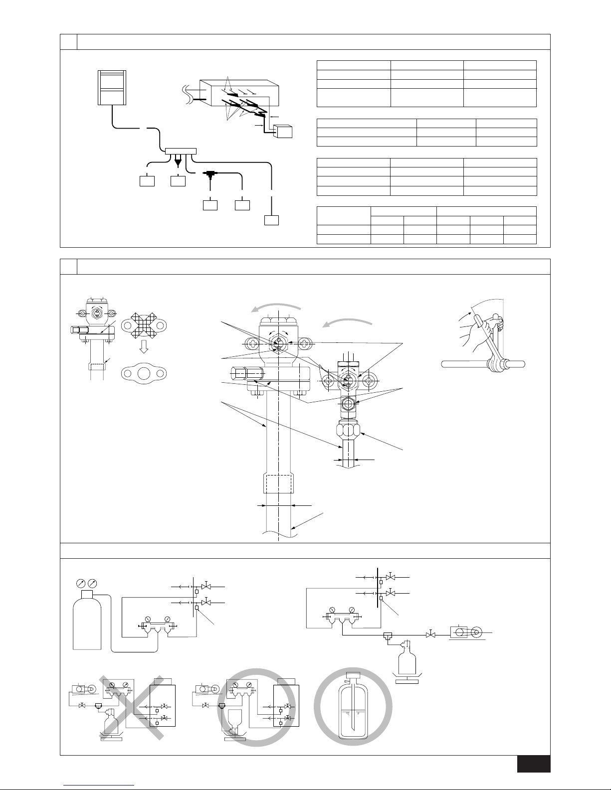
7.2. Refrigerant piping system
Connection Example
[Fig. 7.2.1] (P.3)
Å High press pipe ı Low press pipe
Ç Connection of heat source unit/BC controller
Î Total capacity of indoor units ‰ Liquid line
Ï Gas line Ì Model number
A BC controller B Indoor unit (20~140)
C Indoor unit (200, 250)
3 Please consult with a water quality control specialist about water quality
control methods and water quality calculations before using anti-corrosive
solutions for water quality management.
4 When replacing a previously installed air conditioning device (even when
only the heat exchanger is being replaced), first conduct a water quality
analysis and check for possible corrosion.
Corrosion can occur in cold-water systems even if there has been no prior
signs of corrosion.
If the water quality level has dropped, please adjust water quality sufficiently before replacing the unit.
6.4. Pump interlock
The heat source unit may become damaged if it is operated with no water circulating through the pipes.
Be sure to interlock unit operation and the water-circuit pump. Use the terminal
blocks for interlocking (TB8-3, 4) that can be found on the unit.
In the case of a pump interlock circuit signal connection to the TB8-3, 4, remove
the short-circuit wire. Also, to prevent mistaken error detection, resulting from a
poor connection, in the pressure valve 63PW , use a low maintained current of 5mA
or less.
[Fig. 6.4.1] (P.2)
A Short-circuit wire (Connected before delivery from manufacturer)
B Pump interlock circuit connection
City Multi R2 Series is constituted by an end branching system in which the refrigerant piping from heat source unit is branched at BC controller and connected to
each indoor unit.
The connection method adapted is flange connection for low pressure pipe and
flare connection for high pressure pipe between heat source unit and BC controller,
and flare connection between BC controller and indoor unit. Brazing connection is
employed for joint pipe set and branch pipe set.
Warning:
Always use extreme care to prevent the refrigerant gas (R407C) from leaking
while using fire or flame. If the refrigerant gas comes in contact with the
flame from any source, such as a gas sto ve, it breaks down and generates a
poisonous gas which can cause gas poisoning. Never weld in an un ventilated
room. Always conduct an inspection for gas leakage after installation of the
refrigerant piping has been completed.
7.1. Caution
1 Use the following materials for refrigeration piping.
• Material: Use refrigerant piping made of phosphorus deoxidized copper.
In addition, be sure that the inner and outer surfaces of the pipes are clean
and free of hazardous sulphur, oxides, dust/dirt, shaving particles, oils,
moisture, or any other contaminant. (For R407C models)
2 Commercially available piping often contains dust and other materials. Alwa ys
blow it clean with a dry inert gas.
3 Use care to prevent dust, water or other contaminants from entering the piping
during installation.
4 Reduce the number of bending portions as much as possible, and make bend-
ing radius as big as possible.
5 Always observe the restrictions on the refrigerant piping (such as rated length,
the difference between high/low pressures, and piping diameter). F ailure to do
so can result in equipment failure or a decline in heating/cooling performance.
6 The City Multi Series WR2 will stop due an abnormality due to excessive or
insufficient coolant. At such a time, always properly charge the unit. When
servicing, always check the notes concerning pipe length and amount of additional refrigerant at both locations, the refrigerant volume calculation table on
the back of the service panel and the additional refrigerant section on the labels for the combined number of indoor units.
7 Use liquid refrigerant to fill the system.
8 Never use refrigerant to perform an air purge. Always e vacuate using a v acuum
pump.
9 Always insulate the piping properly. Insufficient insulation will result in a de-
cline in heating/cooling performance, water drops from condensation and other
such problems.
0 When connecting the refrigerant piping, make sure the ball valve of the heat
source unit is completely closed (the factory setting) and do not operate it until
the refrigerant piping for the heat source and indoor units has been connected,
a refrigerant leakage test has been performed and the evacuation process has
been completed.
At the time of shipping, the heat source unit is charged with the refrigerant. As this
charge does not include the amount needed for extended piping, additional charging for each refrigerant line will be required on site. In order that future servicing
may be properly provided, always keep a record of the size and length of each
refrigerant line and the amount of additional charge by writing it in the space provided on the heat source unit.
8.1. Calculation of Additional Refrigerant
Charge
• Calculate the amount of additional charge based on the length of the piping
extension and the size of the refrigerant line.
• Use the table to the right as guide to calculating the amount of additional charg-
ing and charge the system according.
• If the calculation results of the calculation result in a fraction of less than 0.1 kg.
For example, if the result of the calculation was 10.62 kg, round the result up to
10.7 kg.
Page 9

9
GB
D
F
INL
E
PGRRUTR
<Additional Charge>
<Example>
Indoor 1: 40 A: ø19.05 40 m a: ø6.35 10 m
2: 100 B: ø9.52 10 m b: ø9.52 5 m
3: 40 C: ø9.52 15 m c: ø6.35 10 m
4: 32 d: ø6.35 10 m
5: 63 e: ø9.52 10 m
The total length of each liquid line is as follows:
ø19.05: A = 40 m
ø9.52: B + b + e = 10 + 5 + 10 = 25 m
ø6.35: a + c + d = 10 + 10 + 10 = 30 m
Therefore,
<Calculation example>
Additional refrigerant charge
= 40 × 0.16 + 25 × 0.06 + 30 × 0.024 + 2 = 10.7 kg
Value of α
Total capacity of connecting indoor units α
to Model 80 1.0 kg
Models 81 to 160 1.5 kg
Models 161 to 325 2.0 kg
E Open (Operate slowly)
F Cap, copper packing
[Remove the cap and operate the valve stem. Always reinstall the cap after operation is completed. (Valve stem cap tightening torque: 25 N·m (250 kg·cm) or
more)]
G Service port
[Use this port to evacuate the refrigerant piping and add an additional charge at
the site.
Open and close the port using a double-ended wrench.
Always reinstall the cap after operation is completed. (Service port cap tightening
torque: 14 N·m (140 kg·cm) or more)]
H Flare nut
[Tightening torque: 120 N·m (1200 kg·cm)
Loosen and tighten this nut using a double-ended wrench.
Coat the flare contact surface with refrigerator oil (Ester oil, ether oil or alkylbenzene
[small amount]).]
I ø19.05
J ø25.4 (PQRY-P200)
ø28.58 (PQRY-P250)
K Field piping
[Braze to the connecting pipe. (When brazing, use unoxidized brazing.)]
L Close-packed packing
M Hollow packing
Appropriate tightening torque by torque wrench:
Copper pipe external dia. (mm) Tightening torque (N·m) / (kg·cm)
ø6.35 14 to 18 / 140 to 180
ø9.52 35 to 42 / 350 to 420
ø12.7 50 to 57.5 / 500 to 575
ø15.88 75 to 80 / 750 to 800
ø19.05 100 to 140 / 1000 to 1400
Tightening angle standard:
Pipe diameter (mm) Tightening angle (°)
ø6.35, ø9.52 60 to 90
ø12.7, ø15.88 30 to 60
ø19.05 20 to 35
[Fig. 8.2.3] (P.3)
Note:
If a torque wrench is not available, use the following method as a standard:
When you tighten the flare nut with a wrench, you will reach a point where
the tightening torque will abrupt increase. T urn the flare n ut beyond this point
by the angle shown in the table above.
Caution:
• Always remove the connecting pipe from the ball valve and braze it outside the unit.
- Brazing the connecting pipe while it is installed will heat the ball valve and
cause trouble or gas leakage. The piping, etc. inside the unit may also be
burned.
• Use ester oil, ether oil or alkylbenzene (small amount) as the refrigerator
oil to coat flares and flange connections. (For R407C models)
- The refr igerator oil will degrade if it is mixed with a large amount of mineral
oil.
8.3. Airtight test, evacuation, and refrigerant
charging
1 Airtight test
Perform with the stop valv e of the heat source unit closed, and pressuriz e the
connection piping and the indoor unit from the service port provided on the
stop valve of the heat source unit. (Alwa ys pressurize from both the liquid pipe
and the gas pipe service ports.)
[Fig. 8.3.1] (P.3)
A Nitrogen gas B To indoor unit C System analyzer
D Lo Knob E Hi Knob F Stop valve
G Low press pipe H High press pipe I Heat source unit
J Service port
<For R407C models>
The method of conducting the airtight test is basically the same as for R22 models.
However , since the restrictions hav e a large affect on deterioration of the refrigerator oil, always observe them. Also, with nonazeotropic refrigerant (R407C, etc.),
gas leakage causes the composition to change and affects performance. Therefore, perform the airtightness test cautiously.
8.2. Caution for piping connection/valve
operation
• Conduct piping connection and valve operation accurately.
• The gas side connecting pipe is being assembled for shipment.
1 For brazing to the connecting pipe with flange, remove the connecting pipe
with flange from the ball valve, and braze it at the outside of the unit.
2 During the time when removing the connecting pipe with flange, remove
the seal attached on the back side of this sheet and paste it onto the flange
surface of the ball valve to prevent the entry of dust into the valve.
3 The refrigerant circuit is closed with a round, close-packed packing at the
shipment to prevent gas leak between flanges. As no operation can be
done under this state, be sure replace the packing with the hollow packing
attached at the piping connection.
4 At the mounting of the hollow packing, wipe off dust attached on the flange
sheet surface and the packing. Coat refrigerating machine oil (Ester oil,
ether oil or alkylbenzene [small amount]) onto both surfaces of the packing.
[Fig. 8.2.1] (P.3)
• After evacuation and refrigerant charge, ensure that the handle is fully open. If
operating with the valve closed, abnormal pressure will be imparted to the
high- or low-pressure side of the refrigerant circuit, giving damage to the compressor, four-way valve, etc.
• Determine the amount of additional refrigerant charge by using the formula,
and charge refrigerant additionally through the service port after completing
piping connection work.
• After completing work, tighten the service port and cap securely not to gener-
ate gas leak.
[Fig. 8.2.2] (P.3)
<A> [Ball valve (low press side)]
(This figure shows the valve in the fully open state.)
<B> [Ball valve (high press side)]
A Valve stem
[Fully closed at the factory, when connecting the piping, when evacuating, and
when charging additional refrigerant. Open fully after the operations above are
completed.]
B Stopper pin [Prevents the valve stem from turning 90° or more.]
C Packing (Accessory)
[Manufacturer: Nichiasu corporation]
[T ype: T/#1991-NF]
D Connecting pipe (Accessory)
[Use packing and securely install this pipe to the valve flange so that gas leakage
will not occur. (Tightening torque: 25 N·m (250 kg·cm)) Coat both surfaces of the
packing with refrigerator oil (Ester oil, ether oil or alkylbenzene [small amount]).]
Liquid pipe size
Total length of
ø6.35 × 0.024
(m) × 0.024 (kg/m)
Liquid pipe size
Total length of
ø9.52 × 0.06
(m) × 0.06 (kg/m)
Additional
refrigerant charge
(kg)
Liquid pipe size
Total length of
ø19.05 × 0.16
(m) × 0.16 (kg/m)
=+++ α
At the
conditions
below:
Page 10

10
GB
D
F
INL
E
PGRRUTR
2 Evacuation
Evacuate with the ball valve of the heat source unit closed and evacuate both
the connection piping and the indoor unit from the service port provided on the
ball valve of the heat source unit using a vacuum pump . (Always e vacuate from
the service port of both the liquid pipe and the gas pipe.) After the vacuum
reaches 650 Pa [abs], continue evacuation for at least one hour or more.
* Never perform air purging using refrigerant.
[Fig. 8.3.2] (P.3)
A System analyzer B Lo Knob C Hi Knob
D Ball valve E Low press pipe F High press pipe
G Service port H Three-way joint I Valve
J Valve K Cylinder L Scale
M Vacuum pump
Note:
• Always add an appropriate amount of refrigerant. Also always seal the
system with liquid refrigerant. T oo muc h or too little refrigerant will cause
trouble.
• Use a gauge manifold, charging hose, and other parts for the refrigerant
indicated on the unit.
• Use a graviometer. (One that can measure down to 0.1 kg.)
• Use a vacuum pump with a reverse flow check valve. (For R407C models)
(Recommended vacuum gauge: ROBINAIR 14830A Thermistor Vacuum
Gauge)
Also use a vacuum gauge that reaches 0.5 Torr or greater after operating
for five minutes.
3 Refrigerant Charging (For R407C models)
Since the refrigerant used with the unit is nonazerotropic, it must be charged in
the liquid state. Consequently, when charging the unit with refrigerant from a
cylinder, if the cylinder does not have a syphon pipe , charge the liquid refrigerant by turning the cylinder upside-down as shown below. If the cylinder has a
syphon pipe like that shown in the figure at the right, the liquid refrigerant can
be charged with the cylinder standing upright. Therefore , give careful attention
to the cylinder specifications. If the unit should be charged with gas refrigerant,
replace all the refrigerant with new refrigerant. Do not use the refrigerant remaining in the cylinder.
[Fig. 8.3.3] (P.3)
8.4. Thermal insulation of refrigerant piping
Be sure to give insulation work to refrigerant piping by covering liquid pipe and gas
pipe separately with enough thickness heat-resistant polyethylene , so that no gap
is observed in the joint between indoor unit and insulating material, and insulating
materials themselves. When insulation work is insufficient, there is a possibility of
condensation drip, etc. Pay special attention to insulation work to ceiling plenum.
[Fig. 8.4.1] (P.4)
A Steel wire B Piping
C Asphaltic oily mastic or asphalt D Heat insulation material A
E Outer covering B
Glass fiber + Steel wire
Adhesive + Heat - resistant polyethylene foam + Adhesive tape
Indoor Vinyl tape
Floor exposed Water-proof hemp cloth + Bronze asphalt
Heat source
Water-proof hemp cloth + Zinc plate + Oily
paint
Note:
• When using polyethylene cover as covering material, asphalt r oofing shall
not be required.
• No heat insulation must be provided for electric wires.
[Fig. 8.4.2] (P.4)
A Liquid pipe B Gas pipe C Electric wire
D Finishing tape E Insulater
[Fig. 8.4.3] (P.4)
Penetrations
[Fig. 8.4.4] (P.4)
<A> Inner wall (concealed) <B> Outer wall
<C> Outer wall (exposed) <D> Floor (fireproofing)
<E> Roof pipe shaft
<F> Penetrating portion on fire limit and boundary wall
A Sleeve B Heat insulating material
C Lagging D Caulking material
E Band F Waterproofing laye
G Sleeve with edge H Lagging material
I Mortar or other incombustible caulking
J Incombustible heat insulation material
When filling a gap with mortar, cover the penetration part with steel plate so that
the insulation material will not be caved in. F or this part, use incombustible materials for both insulation and covering. (Vinyl covering should not be used.)
Heat
insulation
material A
Outer
covering B
Restriction
• If a flammable gas or air (oxygen) is used as the pressurization
gas, it may catch fire or explode.
• Do not use a refrigerant other than that indicated on the unit.
• Sealing with gas from a cylinder will cause the composition of
the refrigerant in the cylinder to change. (For R407C models)
• Use a pressure gauge, charge box, and other parts especially for
R407C. (For R407C models)
• An electric leak detector for R22 cannot detect leaks of R407C.
• Do not use a haloid torch. (Leaks cannot be detected.)
Airtight test procedure
1. Nitrogen gas pressurization
(1) After pressurizing to the design pressure (2.94 MPa) using nitrogen gas, let stand for about
one day. If the pressure does not drop, airtightness is good.
However, if the pressure drops, since the leaking point is unknown, the following bubble test
may also be performed.
(2) After the pressurization described above, spray the flare connection parts, brazed parts, flanges,
and other parts that may leak with a bubbling agent (Kyuboflex, etc.) and visually check for
bubbles.
(3) After the airtight test, wipe off the bubbling agent.
2. Pressurization using refrigerant gas and nitrogen gas
(1) Pressurizing to a gas pressure of approximately 0.2 MPa, pressurize to the design pressure
(2.94 MPa) using nitrogen gas.
However, do not pressurize at one time. Stop during pressurization and check that the pressure does not drop.
(2) Check for gas leaks by checking the flare connection parts, brazed parts, flanges, and other
parts which may leak using an R407C compatible electric leak detector.
(3) This test may be used together the with bubble type gas leak test.
Page 11

11
GB
D
F
INL
E
PGRRUTR
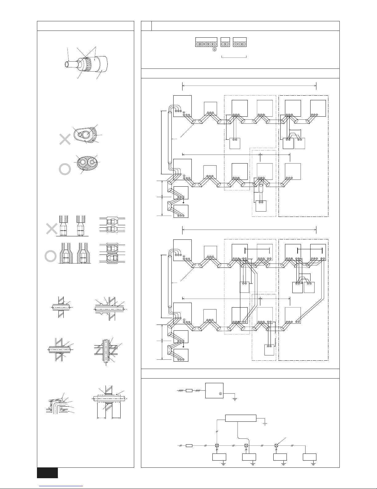
Example of a group operation system with multiple heat source units (Shielding wires and address setting are
necessary.)
<Examples of Transmission Cable Wiring>
[Fig. 9.3.1] M-NET Remote Controller (P.4)
[Fig. 9.3.2] MA Remote Controller (P.4)
A Group 1 B Group 3 C Group 5 D Shielded Wire E Sub Remote Controller
( ) Address
2 Wiring examples
• Controller name, symbol and allowable number of controllers.
2. Remote control cables
Kind of remote control cable
Cable diameter
Remarks
2-core cable (unshielded)
0.3 to 1.25 mm
2
When 10 m is exceeded, use cable with the
same specifications as (1) Transmission line
wiring
9. Wiring
9.1. Caution
1 Follow ordinance of your governmental organization f or technical standard re-
lated to electrical equipment, wiring regulations and guidance of each electric
power company.
2 Wiring for control (hereinafter referred to as transmission line) shall be (5 cm or
more) apart from power source wiring so that it is not influenced by electric
noise from power source wiring. (Do not insert transmission line and power
source wire in the same conduit.)
3 Be sure to provide designated grounding work to heat source unit.
4 Give some allowance to wiring for electrical part box of indoor and heat source
units, because the box is sometimes removed at the time of service work.
5 Never connect the main power source to terminal block of tr ansmission line . If
connected, electrical parts will be burnt out.
6 Use 2-core shield cable for transmission line. If transmission lines of different
systems are wired with the same multiplecore cable, the resultant poor transmitting and receiving will cause erroneous operations.
7 Only the transmission line specified should be connected to the terminal block
for heat source unit transmission.
(Transmission line to be connected with indoor unit : Terminal block TB3 for
transmission line, Other : Terminal block TB7 for centralized control)
Erroneous connection does not allow the system to operate.
8 In case to connect with the upper class controller or to conduct group opera-
tion in different refrigerant systems, the control line for transmission is required
between the heat source units each other.
Connect this control line between the terminal blocks for centralized control.
(2-wire line with no polarity)
When conducting group operation in different refrigerant systems without connecting to the upper class controller, replace the insertion of the short circuit
connector from CN41 of one heat source unit to CN40.
9 Group is set by operating the remote controller.
0 The unused knockout holes should be closed and the opening of refrigerant
pipes, water pipes, power source and transmission wires should be filled with
putty and so on to prevent from rain. (field construction)
9.2. Control box and connecting position of
wiring
1. Connect the indoor unit transmission line to transmission terminal block (TB3),
or connect the wiring between heat source units or the wiring with the central
control system to the central control terminal block (TB7).
Name
heat source unit controller
BC Controller
Indoor Unit Controller
Remote Controller
Symbol
OC
BC
IC
RC
Allowable number of controllers
One controller for one OC
Two to ten controllers for one OC
Maximum of two per group
When using shielded wiring, connect shield ground of the indoor unit transmission line to the earth screw (
) and connect shield ground of the line between
heat source units and the central control system transmission line to the shield
(S) terminal of the central control terminal block (TB7) shield (S) terminal. In
addition, in the case of heat source units whose power supply connector CN41
has been replaced by CN40, the shield terminal (S) of terminal block (TB7) of
the central control system should also be connected to the ground (
).
[Fig. 9.2.1] (P.4)
A Power source B Transmission line
2. Conduit mounting plates (ø27) are being provided. P ass the power supply and
transmission wires through the appropriate knock-out holes, then remove the
knock-out piece from the bottom of the terminal box and connect the wires.
3. Fix power source wiring to terminal box by using buffer bushing for tensile
force (PG connection or the like).
9.3. Wiring transmission cables
1 Types of control cables
1. Wiring transmission cables
• Types of transmission cables: Shielding wire CVVS or CPEVS
• Cable diameter: More than 1.25 mm
2
• Maximum wiring length: Within 200 m
<Wiring Method and Address Settings>
a. Always use shielded wire when making connections between the heat source unit (OC) and the indoor unit (IC), as well for all OC-OC, and IC-IC wiring intervals.
b. Use feed wiring to connect terminals M1 and M2 and the ground terminal on the transmission cable terminal block (TB3) of each heat source unit (OC) to terminals M1,
M2 and terminal S on the transmission cable block of the indoor unit (IC).
c. Connect terminals 1 (M1) and 2 (M2) on the transmission cable terminal block of the indoor unit (IC) that has the most recent address within the same group to the
terminal block on the remote controller (RC).
d. Connect together terminals M1, M2 and terminal S on the terminal block for central control (TB7) for the heat source unit (OC).
e. On one heat source unit only, change the jumper connector on the control panel from CN41 to CN40.
f. Connect the terminal S on the terminal block for central control (TB7) for the heat source unit (OC) for the unit into which the jumper connector was inserted into CN40
in Step above to the ground terminal
in the electrical component box.
g. Set the address setting switch as follows.
* To set the heat source unit address to 100, the heat source address setting switch must be set to 50.
Unit Range Setting Method
IC (Main) 01 to 50 Use the most recent address within the same group of indoor units
IC (Sub) 01 to 50
Use an address, other than that of the IC (Main) from among the units within the same group of indoor units. This must be
in sequence with the IC (Main)
Heat source Unit 51 to 100 Use the most recent address of all the indoor units plus 50
BC controller 51 to 100 Heat source unit address plus 1
M-NET R/C (Main) 101 to 150 Set at an IC (Main) address within the same group plus 100
M-NET R/C (Sub) 151 to 200 Set at an IC (Main) address within the same group plus 150
MA R/C – Unnecessary address setting (Necessary main/sub setting)
h. The group setting operations among the multiple indoor units is done by the remote controller (RC) after the electrical power has been turned on.
Page 12

12
GB
D
F
INL
E
PGRRUTR
10.Test run
10.1. The following phenomena do not represent trouble (emergency)
Display of remote controller
Normal display
“Cooling (heating)” flashes
Normal display
Normal display
Defrost display
No lighting
Heat ready
Normal display
“HO” flashes
Light out
Cause
This is not a trouble as it is just a selecting sound.
When multiple indoor units (max. 3) are connected to the same branch of the BC
controller, the heating (cooling) operation cannot be performed while another
indoor unit is performing a cooling (heating) operation.
Because of the control operation of auto vane, it may change over to horizontal
blow automatically from the downward blow in cooling in case the downward
blow operation has been continued for 1 hour . At defrosting in heating, hot adjusting and thermostat OFF, it automatically changes over to horizontal blow.
Ultra-low speed operation is commenced at thermostat OFF.
Light air automatically changes over to set value by time or piping temper ature at
thermostat ON.
The fan is to stop during defrosting.
Fan is to run for 1 minute after stopping to e xhaust residual heat (only in heating).
Ultra low-speed operation for 5 minutes after SW ON or until piping temperature
becomes 35°C, low speed operation for 2 minutes thereafter, and then set notch
is commenced. (Hot adjust control)
When the heat source unit is being cooled and the refrigerant is resting, warming
up operation is performed for at least 35 minutes to warm the compressor.
During this time, only the fan operates.
System is being driven.
Operate remote controller again after “HO” disappear.
After a stop of cooling operation, unit continues to operate drain pump for three
minutes and then stops it.
Unit continues to operate drain pump if drainage is generated, even during a
stop.
Phenomenon
Indoor unit and BC controller generate sound
at the cooling/heating change over sometime.
Indoor unit does not the perform cooling (heating) operation.
The auto vane runs freely.
Fan setting changes during heating.
Fan stops during heating operation.
Fan does not stop while operation has been
stopped.
No setting of fan while start SW has been
turned on.
Heat source unit does not operate by turning
switch on.
Indoor unit remote controller shows “HO” indicator for about two minutes when turning
ON universal power supply.
Drain pump does not stop while unit has been
stopped.
Drain pump continues to operate while unit
has been stopped.
<Permissible Lengths>
1 M-NET Remote controller
• Max length via heat source units: L
1+L2+L3+L4 and L1+L2+L3+L5 and L1+L2+L6+L7
=
500 m (1.25 mm2 or more)
• Max transmission cable length: L
1 and L3+L4 and L3+L5 and L6 and L2+L6 and L7
=
200 m (1.25 mm2 or more)
• Remote controller cable length:r
1, r2, r3, r4
=
10 m (0.3 to 1.25 mm2)
If the length exceeds 10 m, use a 1.25 mm
2
shielded wire. The length of this section (L8) should be included in the calculation of the
maximum length and overall length.
2 MA Remote controller
• Max length via heat source unit (M-NET cable): L
1+L2+L3+L4 and L1+L2+L6+L7
=
500 m (1.25 mm2 or more)
• Max transmission cable length (M-NET cable): L
1 and L3+L4 and L6 and L2+L6 and L7
=
200 m (1.25 mm2 or more)
• Remote controller cable length:c
1 and c1+c2+c3 and c1+c2+c3+c4
=
200 m (0.3 to 1.25 mm2)
9.4. Wiring of main power supply and equipment capacity
Schematic Drawing of Wiring (Example)
[Fig. 9.4.1] (P.4)
A Switch (Breakers for Wiring and Current Leakage) B Heat source Unit C BC Controller
D Pull Box E Indoor Unit
Thickness of Wire for Main Power Supply and On/Off Capacities
1. Use a separate power supply for the heat source unit and indoor unit.
2. Bear in mind ambient conditions(ambient temperature,direct sunlight, rain water,etc.) when proceeding with the wiring and connections.
3. The wire size is the minimum value for metal conduit wiring. The power cord size should be 1 rank thicker consideration of voltage drops.
Make sure the power-supply voltage does not drop more than 10 %.
4. Specific wiring requirements should adhere to the wiring regulations of the reglon.
5. Power supply cords of parts of appliances for heat source use shall not be lighter than polychloroprene sheathed flexible cord (design 245 IEC57).
6. A switch with at least 3 mm contact separation in each pole shall be provided by the Air conditioner installation.
Warning:
• Be sure to use specified wires to connect so that no external force is imparted to terminal connections. If connections are not fixed firmly, it may cause
heating or fire.
• Be sure to use the appropriate type of overcurrent protection switch. Note that generated overcurrent may include some amount of direct current.
Caution:
• Some installation site may require attachment of an earth leakage breaker. If no earth leakage breaker is installed, it may cause an electric shock.
• Do not use anything other than breaker and fuse with correct capacity. Using fuse and wire or copper wire with too lar ge capacity ma y cause a malfunction
of unit or fire.
30A 100mA 0.1sec. or less
40A 100mA 0.1sec. or less
20A 30mA 0.1sec. or less
40A
40A
20A
32
40
16
32
40
16
4.0
6.0
1.5
4.0
6.0
1.5
BC controller
Indoor Unit
Main Cable
Switch (A)
Minimum Wire Thickness (mm
2
)
Branch Capacity Fuse
Breaker for Current Leakage
Model
Heat source
Unit
P200
P250
–
–
1.5
Breaker for
Wiring (NFB)
Ground
Page 13

WT03600X01
Printed in Japan
HEAD OFFICE: MITSUBISHI DENKI BLDG., 2-2-3, MARUNOUCHI, CHIYODA-KU, TOKYO 100-8310, JAPAN
Please be sure to put the contact address/telephone number on
this manual before handing it to the customer.
The product at hand is
based on the following
EU regulations:
• Low Voltage Directive 73/23/EEC
• Electromagnetic Compatibility Directive 89/
336/EEC
This product is designed and intended for use in the residential, commer-
cial and light-industrial environment.
 Loading...