

Mitsubishi Electric Air-Conditioners For Building Application, CITY MULTI PMFY-P-NBMU-E Installation Manual

INSTALLATION MANUAL
For safe and correct use, please read this installation manual thoroughly before installing the air-conditioner unit.
Air-Conditioners For Building Application
INDOOR UNIT
PMFY-P·NBMU-E
2
Contents
1. Safety precautions ................................................................................... 2
2. Installing the indoor unit ........................................................................... 3
3. Installing the refrigerant piping ................................................................. 5
4. Drainage piping work ............................................................................... 6
5. Electrical work .......................................................................................... 7
6. Test run .................................................................................................... 9
7. Installing the grille .................................................................................... 9
1.2. Before installation or relocation
Caution:
• Be extremely careful when transporting the units. Two or more persons are
needed to handle the unit, as it weighs 44 lbs. (20 kg) or more. Do not grasp
the packaging bands. Wear protective gloves as you can injure your hands
on the fins or other parts.
• Be sure to safely dispose of the packaging materials. Packaging materials,
such as nails and other metal or wooden parts may cause stabs or other
injuries.
Warning:
• Ask a dealer or an authorized technician to install the unit.
• For installation work, follow the instructions in the Installation Manual and use
tools and pipe components specifically made for use with refrigerant specified in the outdoor unit installation manual.
• The unit must be installed according to the instructions in order to minimize
the risk of damage from earthquakes, typhoons, or strong winds. An incorrectly installed unit may fall down and cause damage or injuries.
• The unit must be securely installed on a structure that can sustain its weight.
• If the air conditioner is installed in a small room, measures must be taken to
prevent the refrigerant concentration in the room from exceeding the safety
limit in the event of refrigerant leakage. Should the refrigerant leak and cause
the concentration limit to be exceeded, hazards due to lack of oxygen in the
room may result.
• Ventilate the room if refrigerant leaks during operation. If refrigerant comes
into contact with a flame, poisonous gases will be released.
• All electric work must be performed by a qualified technician according to
local regulations and the instructions given in this manual.
• Use only specified cables for wiring.
• The terminal block cover panel of the unit must be firmly attached.
• Use only accessories authorized by Mitsubishi Electric and ask a dealer or
an authorized technician to install them.
• The user should never attempt to repair the unit or transfer it to another location.
• After installation has been completed, check for refrigerant leaks. If refrigerant leaks into the room and comes into contact with the flame of a heater or
portable cooking range, poisonous gases will be released.
1.1. Before installation (Euvironment)
Caution:
• Do not use the unit in an unusual environment. If the air conditioner is installed in areas exposed to steam, volatile oil (including machine oil), or
sulfuric gas, areas exposed to high salt content such as the seaside, the
performance can be significantly reduced and the internal parts can be damaged.
• Do not install the unit where combustible gases may leak, be produced, flow,
or accumulate. If combustible gas accumulates around the unit, fire or explosion may result.
• Do not keep food, plants, caged pets, artwork, or precision instruments in
the direct airflow of the indoor unit or too close to the unit, as these items can
be damaged by temperature changes or dripping water.
• When the room humidity exceeds 80% or when the drainpipe is clogged, water may drip from the indoor unit. Do not install the indoor unit where such
dripping can cause damage.
• When installing the unit in a hospital or communications office, be prepared
for noise and electronic interference. Inverters, home appliances, high-frequency medical equipment, and radio communications equipment can cause
the air conditioner to malfunction or breakdown. The air conditioner may
also affect medical equipment, disturbing medical care, and communications
equipment, harming the screen display quality.
• Thermal insulation of the refrigerant pipe is necessary to prevent condensation. If the refrigerant pipe is not properly insulated, condensation will be formed.
• Place thermal insulation on the pipes to prevent condensation. If the drainpipe is installed incorrectly, water leakage and damage to the ceiling, floor,
furniture, or other possessions may result.
• Do not clean the air conditioner unit with water. Electric shock may result.
• Tighten all flare nuts to specification using a torque wrench. If tightened too
much, the flare nut can break after an extended period.
1.3. Before electric work
Caution:
• Be sure to install circuit breakers. If not installed, electric shock may result.
• For the power lines, use standard cables of sufficient capacity. Otherwise, a
short circuit, overheating, or fire may result.
• When installing the power lines, do not apply tension to the cables.
• Be sure to ground the unit. If the unit is not properly grounded, electric shock
may result.
• Use circuit breakers (ground fault interrupter, isolating switch (+B fuse), and
molded case circuit breaker) with the specified capacity. If the circuit breaker
capacity is larger than the specified capacity, breakdown or fire may result.
1. Safety precautions
1.4. Before starting the test run
Caution:
• Turn on the main power switch more than 12 hours before starting operation.
Starting operation just after turning on the power switch can severely damage the internal parts.
• Before starting operation, check that all panels, guards and other protective
parts are correctly installed. Rotating, hot, or high voltage parts can cause
injuries.
• Do not operate the air conditioner without the air filter set in place. If the air
filter is not installed, dust may accumulate and breakdown may result.
• Do not touch any switch with wet hands. Electric shock may result.
• Do not touch the refrigerant pipes with bare hands during operation.
• After stopping operation, be sure to wait at least five minutes before turning
off the main power switch. Otherwise, water leakage or breakdown may result.
s Before installing the unit, make sure you read all the “Safety precau-
tions”.
s Please report to your supply authority or obtain their consent before
connecting this equipment to the power supply system.
Warning:
Describes precautions that must be observed to prevent danger of injury or
death to the user.
Caution:
Describes precautions that must be observed to prevent damage to the unit.
After installation work has been completed, explain the “Safety Precautions,” use,
and maintenance of the unit to the customer according to the information in the Operation Manual and perform the test run to ensure normal operation. Both the Installation Manual and Operation Manual must be given to the user for keeping. These
manuals must be passed on to subsequent users.
: Indicates a part which must be grounded.
Warning:
Carefully read the labels affixed to the main unit.
3
A
9-3/8 (247)
2-1/16(53)
11/16
(17.5)
11/16
(17.5)
13/16 (20)13/16 (20)
1-1/8
(28)
1-1/8 (28)
1-25/32 (45)
13/16 (20)
1-3/4 (45)
3/4 (20)
13-1/2 (340)
3
17 (430)
2
18-1/2 (470)
1
1-1/32 (26)
2-15/18 (74.5)
13/16 (20)
1-1/32 (26)
2-15/18 (74.5)
13/16 (20)
29-7/8 (759)
31-15/18 (811)
3
37-13/16 (960)
2
39-3/8 (1000)
1
4
2-11/16
(69)
2. Installing the indoor unit
1
2
3
4
6
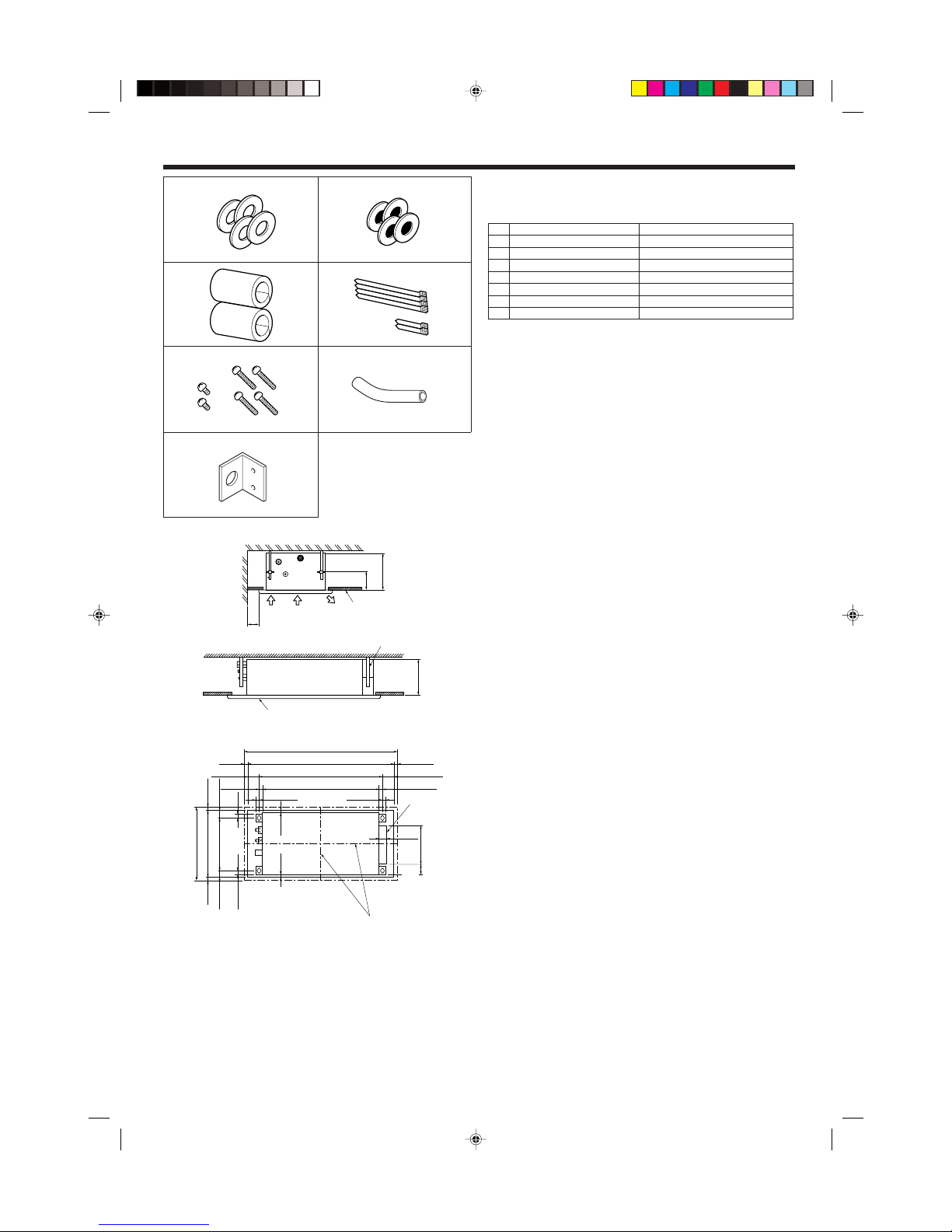
2.1. Check the indoor unit accessories (Fig. 2-1)
The indoor unit should be supplied with the following spare parts and accessories
(contained in the inside of the intake grille).
Accessory name Q’ty
1 Washer 4 pcs
2 Washer (with insulation) 4 pcs
3 Pipe cover 2 pcs
4 Band 4 pcs (Long) 2 pc (Short)
5 Screw 4 pcs M5 × 0.8 × 30 2 pcs M4 × 12
6 Glass tube 1pc
7 Plate for conduit 1pc
Fig. 2-1
5
7
2.2. Service space (Fig. 2-2)
• The dimensions of ceiling opening can be regulated within the range shown in
following diagram; so center the main unit against the opening of ceiling, ensuring
that the respective opposite sides on all sides of the clearance between them becomes identical.
A Air intake
B Air outlet
C Ceiling panel
D Min. 7-7/8 in. (200 mm)
E Suspension bolts W3/8 or M10
F Grille
2.3. Ceiling openings and suspension bolt installation
locations (Fig. 2-3)
• Make an opening in the ceiling 17 in × 37-7/8 in (430 mm × 960 mm) in size. This
functions as a check window and will be needed later during servicing.
• If the dimensions are not accurate, when the grille is installed there may be gaps
between it and the indoor unit. This may result in dripping water or other problems.
• When deciding on placement, consider carefully the space around the ceiling and
make your measurements generous.
• Ceiling types and building construction differ. Therefore you should consult with the
builder and decorator.
A The centers of the ceiling opening and the indoor unit should be aligned.
1 Outer side of grille
2 Ceiling opening
3 Bolt pitch
4 Electric box
• Using the installation template (top of the package) and the gauge (supplied as an
accessory with the grille), make an opening in the ceiling so that the main unit can
be installed as shown in the diagram. (The method for using the template and the
gauge are shown.)
• Use M10 (3/8") suspension bolts.
* Suspension bolts are to be procured at the field.
• After suspending the indoor unit, you will have to connect the pipes and wiring
above the ceiling. Once the location has been fixed and the direction of the pipes
has been determined, place the refrigerant and drainage pipes, the wiring for the
remote controller, and the wiring that connects the indoor and outdoor units in their
desired locations before suspending the indoor unit. This is especially important in
cases where the ceiling is already in existence.
C
A
D
AB
4-5/16
(110)
9-1/16(230)
E
F
9-1/16(230)
Fig. 2-2
Fig. 2-3
in (mm)
in (mm)
4
D
E
F
G
13-1/2
(340)
31-7/8 (811)
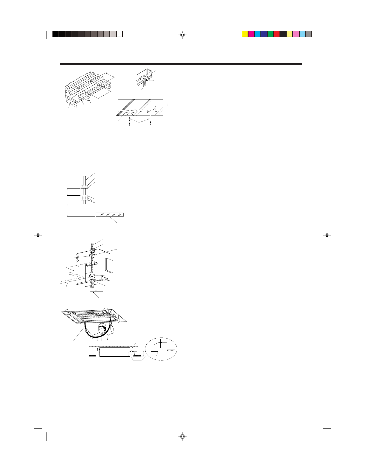
Check the pitch of the suspension bolt. (13-1/2 in. × 32 in. (340 mm × 811 mm)) (Fig.
2-6)
1. Thread washers 1 2 (supplied) and their nuts (procured locally) onto the sus-
pension bolt in advance.
* Do this in the following order (from the top): nut, insulated washer 2, washer
without insulation 1, two nuts.
* Position insulated washer 2 with the insulated surface pointing down, as in the
figure.
2. Lift the unit into place, aligned properly with the suspension bolt. Pass the bracket
between washers 1 and 2, which are already in place, and secure it. Do the
same in all four places.
* Make sure the suspension bolt extends 3/4 in. (20 mm) or more from the surface
of the ceiling. Otherwise you will not be able to install the cover panel (sold separately).
3. If the long opening in the bracket and opening in the ceiling do not align, adjust
them until they do.
4. Check that the four corners are all level, using a spirit level or clear plastic tubing
with water in it.
* Make sure that any slant in the unit after installation is less than 0.5 degrees
(approx. 1/4 in. (6 mm) on the long dimension of the unit).
5. Tighten all the nuts. (Fig. 2-7)
B
in. (mm)
in. (mm)
Fig. 2-6
A Suspension bolt (3/8" or M10)
B Ceiling surface
C Nut (3/8" or M10)
D Washer 2 (with insulation)
E Washer 1
F (Install with insulation facing down)
G Measurement to upper face of bracket
A Suspension bolt (3/8" or M10)
B Clear plastic tubing
C Underside of bracket
D Secure front panel here
E Make these surfaces are flush with each other (0 - 1/8 in. (0 - 3 mm))
Fig. 2-7
K
L
M
J
H
I
in. (mm)
in. (mm)
Fig. 2-4
Fig. 2-5
D Ceiling panel
E Rafter
F Beam
G Roof beam
H Use inserts rated at 250-350 lbs (100-150 kg) each (procure locally)
I Suspension bolts 3/8" (M10) (procure locally)
J Steel reinforcing rod
K C channel
L Channel suspension bracket
M M10 suspension bolt
2.4. Unit suspension procedures (Fig. 2-5)
Procure 3/8" bolts or M10 bolts locally.
• Adjust the length of the bolt’s protrusion from the ceiling surface beforehand.
*1. When using an extra upper nut in suspending the unit, in some cases you may
have to add it later.
A Suspension bolt
B Ceiling panel
C Nut
D Washer (with insulation) 2
E Washer (without insulation) 1
2. Installing the indoor unit
1 Wooden structures (Fig. 2-4)
• Use tie beams (single storied houses) or second floor beams (two story houses) as
reinforcing members.
• Wooden beams for suspending air conditioners must be sturdy and their sides
must be at least 2-3/8 in. (6 cm) long if the beams are separated by not more than
35-7/16 in. (90 cm) and their sides must be at least 3-9/16 in. (9 cm) long if the
beams are separated by as much as 70-7/8 in. (180 cm). The size of the suspension bolts should be 3/8" (ø10). (The bolts do not come with the unit.)
• Use channel, duct and other parts procured locally to suspend the indoor unit.
2 Ferro-concrete structures
Secure the suspension bolts using the method shown, or use steel or wooden hangers, etc. to install the suspension bolts.
A
C
D
E
C *1
B
Min. 51/64(20) Min. 1-3/16(30)
F
G
B
B
C
*
E
*
D
C
A
4-13/32(112)
Min. 51/64(20)
4-21/64
(110)
A
C
D
E
4-21/64
(110)
 Loading...