

Mitsubishi Electric CITY MULTI PLFY-M-VEM Operation Manual

Air-Conditioners For Building Application
INDOOR UNIT
Bina Uygulaması için Klimalar
İÇ ÜNİTE
PLFY-M·VEM Series
OPERATION MANUAL
For safe and correct use, please read this operation manual thoroughly before operating the air-conditioner unit.
IŞLETME ELKITABI
Emniyetli ve doğru biçimde nasıl kullanılacağını öğrenmek için lütfen klima cihazını işletmeden önce bu
elkitabını dikkatle okuyunuz.
FOR USER
KULLANICI İÇİN
English
Türkçe
Manual Download
http://www.mitsubishielectric.com/ldg/ibim/
en Go to the above website to download manuals, select model name, then choose language.
de Besuchen Sie die oben stehende Website, um Anleitungen herunterzuladen, wählen Sie den Modellnamen und dann die Sprache aus.
fr Rendez-vous sur le site Web ci-dessus pour télécharger les manuels, sélectionnez le nom de modèle puis choisissez la langue.
nl Ga naar de bovenstaande website om handleidingen te downloaden, de modelnaam te selecteren en vervolgens de taal te kiezen.
es Visite el sitio web anterior para descargar manuales, seleccione el nombre del modelo y luego elija el idioma.
it Andare sul sito web indicato sopra per scaricare i manuali, selezionare il nome del modello e scegliere la lingua.
el Μεταβείτε στον παραπάνω ιστότοπο για να κατεβάσετε εγχειρίδια. Επιλέξτε το όνομα του μοντέλου και, στη συνέχεια, τη γλώσσα.
pt Aceda ao site Web acima indicado para descarregar manuais, seleccione o nome do modelo e, em seguida, escolha o idioma.
da Gå til ovenstående websted for at downloade manualer og vælge modelnavn, og vælg derefter sprog.
sv Gå till ovanstående webbplats för att ladda ner anvisningar, välj modellnamn och välj sedan språk.
tr Kılavuzları indirmek için yukarıdaki web sitesine gidin, model adını ve ardından dili seçin.
ru Чтобы загрузить руководства, перейдите на указанный выше веб-сайт; выберите название модели, а затем язык.
uk Щоб завантажити керівництва, перейдіть на зазначений вище веб-сайт; виберіть назву моделі, а потім мову.
bg Посетете горепосочения уебсайт, за да изтеглите ръководства, като изберете име на модел и след това – език.
pl Odwiedź powyższą stronę internetową, aby pobrać instrukcje, wybierz nazwę modelu, a następnie język.
no Gå til nettstedet over for å laste ned håndbøker og velg modellnavn, og velg deretter språk.
Mene yllä mainitulle verkkosivulle ladataksesi oppaat, valitse mallin nimi ja valitse sitten kieli.
cs Příručky naleznete ke stažení na internetové stránce zmíněné výše poté, co zvolíte model a jazyk.
sk Na webovej stránke vyššie si môžete stiahnuť návody. Vyberte názov modelu a zvoľte požadovaný jazyk.
hu A kézikönyvek letöltéséhez látogasson el a fenti weboldalra, válassza ki a modell nevét, majd válasszon nyelvet.
sl Obiščite zgornjo spletno stran za prenos priročnikov; izberite ime modela, nato izberite jezik.
ro Accesaţi site-ul web de mai sus pentru a descărca manualele, selectaţi denumirea modelului, apoi alegeţi limba.
et Kasutusjuhendite allalaadimiseks minge ülaltoodud veebilehele, valige mudeli nimi ja seejärel keel.
lv Dodieties uz iepriekš norādīto tīmekļa vietni, lai lejupielādētu rokasgrāmatas; tad izvēlieties modeļa nosaukumu un valodu.
lt Norėdami atsisiųsti vadovus, apsilankykite pirmiau nurodytoje žiniatinklio svetainėje, pasirinkite modelio pavadinimą, tada – kalbą.
hr Kako biste preuzeli priručnike, idite na gore navedeno web-mjesto, odaberite naziv modela, a potom odaberite jezik.
sr Idite na gore navedenu veb stranicu da biste preuzeli uputstva, izaberite ime modela, a zatim izaberite jezik.
Contents
1. Safety Precautions ............................................................................. 1
2. Parts Names ....................................................................................... 2
3. Operation ............................................................................................ 5
4. Timer................................................................................................. 13
Note:
The phrase “Wired remote controller” in this operation manual refers only to the PAR-40MAA.
If you need any information for the other remote controller, please refer to the instruction book included in this box.
5. Emergency Operation for Wireless Remote-controller ..................... 13
6. Care and Cleaning............................................................................ 14
7. Troubleshooting ................................................................................ 15
8. Specifications ................................................................................... 17
1. Safety Precautions
Before installing the unit, make sure you read all the “Safety Precautions”.
The “Safety Precautions” provide very important points regarding safety. Make sure you follow them.
Please report to or take consent by the supply authority before connection to the system.
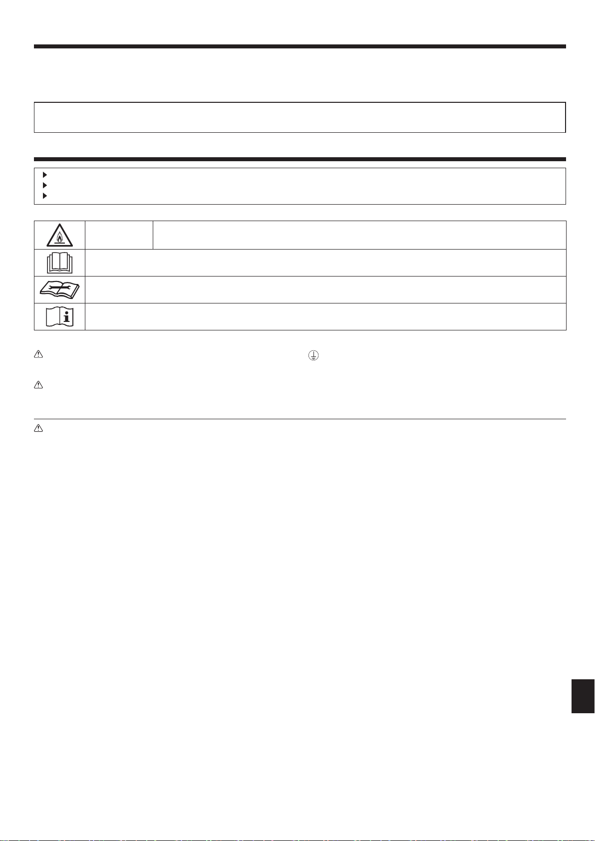
MEANINGS OF SYMBOLS DISPLAYED ON THE UNIT
WARNING
(Risk of re)
Read the OPERATION MANUAL carefully before operation.
Service personnel are required to carefully read the OPERATION MANUAL and INSTALLATION MANUAL before operation.
Further information is available in the OPERATION MANUAL, INSTALLATION MANUAL, and the like.
Symbols used in the text
Warning:
Describes precautions that should be observed to prevent danger
of injury or death to the user.
Caution:
Describes precautions that should be observed to prevent damage to
the unit.
This mark is for R32 refrigerant only. Refrigerant type is written on nameplate of outdoor unit.
In case that refrigerant type is R32, this unit uses a ammable refrigerant.
If refrigerant leaks and comes in contact with re or heating part, it will create harmful gas and there is risk of re.
Symbols used in the illustrations
: Indicates a part which must be grounded.
Warning:
• These appliances are not accessible to the general public.
• The unit must not be installed by the user. Ask the dealer or an
authorized company to install the unit. If the unit is installed
improperly, water leakage, electric shock or fire may result.
• Do not alter the unit. It may cause fire, electric shock, injury or
water leakage.
• Do not stand on, or place any items on the unit.
• Do not splash water over the unit and do not touch the unit with
wet hands. An electric shock may result.
• Do not spray combustible gas close to the unit. Fire may result.
• Do not place a gas heater or any other open-flame appliance
where it will be exposed to the air discharged from the unit.
Incomplete combustion may result.
• Do not remove the front panel or the fan guard from the outdoor
unit when it is running.
• Never repair the unit or transfer it to another site by yourself.
• When you notice exceptionally abnormal noise or vibration, stop
operation, turn off the power switch, and contact your dealer.
• Never insert fingers, sticks etc. into the intakes or outlets.
• If you detect odd smells, stop using the unit, turn off the power
switch and consult your dealer. Otherwise, a breakdown, electric
shock or fire may result.
• This air conditioner is NOT intended for use by children or infirm
persons without supervision.
• Young children must be supervised to ensure that they do not
play with the air conditioner.
• If the refrigeration gas blows out or leaks, stop the operation of
the air conditioner, thoroughly ventilate the room, and contact
your dealer.
• This appliance is intended to be used by expert or trained users
in shops, in light industry and on farms, or for commercial use by
lay persons.
• This appliance can be used by children aged from 8 years and
above and persons with reduced physical, sensory or mental
capabilities or lack of experience and knowledge if they have
been given supervision or instruction concerning use of the
appliance in a safe way and understand the hazards involved.
Children shall not play with the appliance. Cleaning and user
maintenance shall not be made by children without supervision.
• This appliance is not intended for use by persons (including
children) with reduced physical, sensory or mental capabilities,
or lack of experience and knowledge, unless they have been
given supervision or instruction concerning use of the appliance
by a person responsible for their safety.
• Children should be supervised to ensure that they do not play
with the appliance.
• This appliance can be used by children aged from 8 years and
above and persons with reduced physical, sensory or mental
capabilities or lack of experience and knowledge if they have
been given supervision or instruction concerning use of the
appliance in a safe way and understand the hazards involved.
Children shall not play with the appliance. Cleaning and user
maintenance shall not be made by children without supervision.
• When installing or relocating, or servicing the air conditioner, use
only the specified refrigerant written on outdoor unit to charge
the refrigerant lines. Do not mix it with any other refrigerant and
do not allow air to remain in the lines.
If air is mixed with the refrigerant, then it can be the cause of
abnormal high pressure in the refrigerant line, and may result in
an explosion and other hazards.
The use of any refrigerant other than that specified for the
system will cause mechanical failure or system malfunction or
unit breakdown. In the worst case, this could lead to a serious
impediment to securing product safety.
• This unit should be installed in rooms which exceed the floor
space specified in outdoor unit installation manual.
Refer to outdoor unit installation manual.
• Do not use means to accelerate the defrosting process or to
clean, other than those recommended by the manufacturer.
• The appliance shall be stored in a room without continuously
operating ignition sources (for example: open flames, an
operating gas appliance or an operating electric heater).
• Do not pierce or burn.
• Be aware that refrigerants may not contain an odour.
en
1
1. Safety Precautions
Caution:
• Do not use any sharp object to push the buttons, as this may
damage the remote controller.
•
Never block or cover the indoor or outdoor unit’s intakes or outlets.
• Never wipe the remote controller with benzene, thinner chemical
rags, etc.
• Do not operate the unit for a long time in high humidity, e.g.
leaving a door or window open. In the cooling mode, if the unit
is operated in a room with high humidity (80% RH or more) for a
long time, water condensed in the air conditioner may drop and
wet or damage furniture, etc.
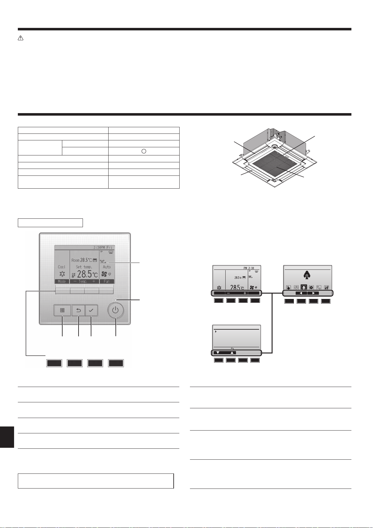
2. Parts Names
■ Indoor Unit
PLFY-M·VEM
Fan steps 4 steps + Auto
Vane
Louver ―
Filter Long-life
Filter cleaning indication 2,500 hr
Enter the model setting number for
the indoor unit you want to operate.
* For systems that are capable of simultaneous cooling and heating operation, use
the setting indicated in parentheses ( ). For details on the setting procedure, refer
to the Installation Manual.
■
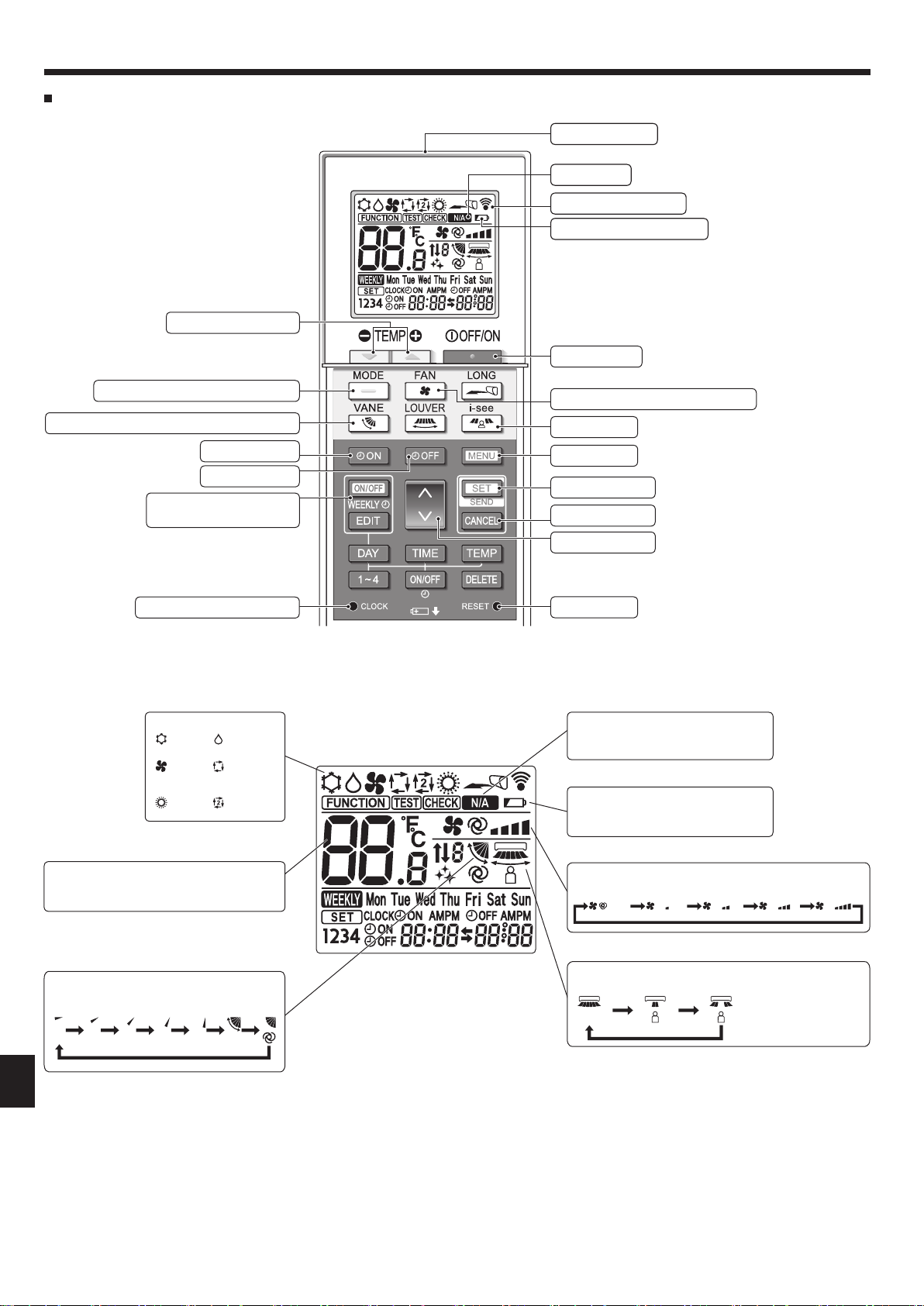
Wired Remote Controller
Controller interface
Steps 5 steps
Auto Swing
065 (001)
• Do not touch the upper air outlet vane or the lower air outlet
damper during operation. Otherwise, condensation may form and
the unit may stop operating.
Disposing of the unit
When you need to dispose of the unit, consult your dealer.
Air outlet
Vane
The functions of the function buttons change depending on the
screen.
Refer to the button function guide that appears at the bottom of the
LCD for the functions they serve on a given screen.
When the system is centrally controlled, the button function guide
that corresponds to the locked button will not appear.
Filter
Air intake
4 3 2
1
Function buttons
7 8 9 0
▌1 [ON/OFF] button
Press to turn ON/OFF the indoor unit.
▌2 [SELECT] button
Press to save the setting.
▌3 [RETURN] button
Press to return to the previous screen.
▌4 [MENU] button
en
Press to bring up the Main menu.
▌5 Backlit LCD
Operation settings will appear.
When the backlight is off, pressing any button turns the backlight on
and it will stay lit for a certain period of time depending on the screen.
When the backlight is off, pressing any button turns the backlight on
and does not perform its function. (except for the [ON/OFF] button)
5
Main display Main menu
Room
Set temp.
Cool Auto
Mode Temp. Fan
Fri
Main Main menu
Energy saving
6
7 8 9 0
Menu screen
Operation
Vane·Louver·Vent. (Lossnay)
High power
Comfort
Main display:
Cursor
7 8 9 0
Function guide
7 8 9 0
▌6 ON/OFF lamp
This lamp lights up in green while the unit is in operation. It blinks while
the remote controller is starting up or when there is an error.
▌7 Function button [F1]
Main display: Press to change the operation mode.
Menu screen: The button function varies with the screen.
▌8 Function button [F2]
Main display: Press to decrease temperature.
Main menu: Press to move the cursor left.
Menu screen: The button function varies with the screen.
▌9 Function button [F3]
Main display: Press to increase temperature.
Main menu: Press to move the cursor right.
Menu screen: The button function varies with the screen.
▌0 Function button [F4]
Main display: Press to change the fan speed.
Menu screen: The button function varies with the screen.
2
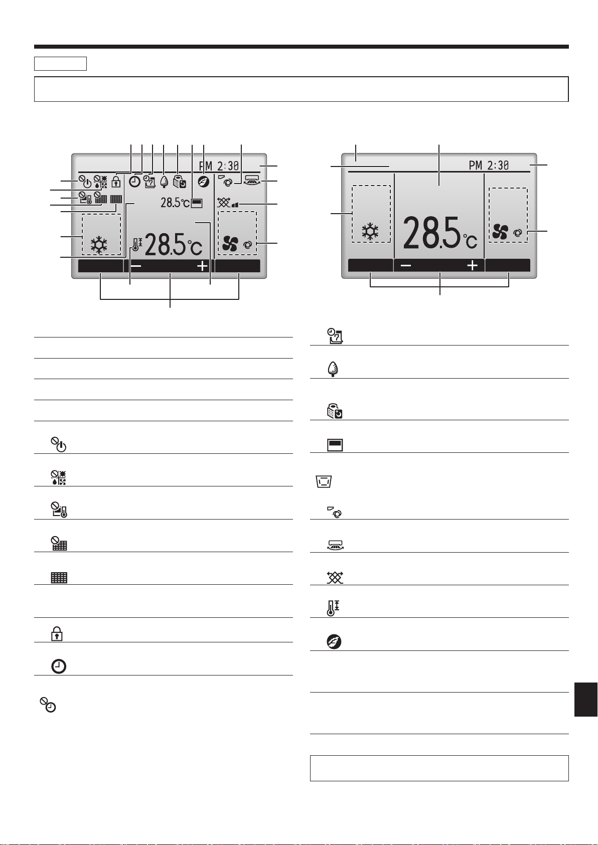
2. Parts Names
Display
The main display can be displayed in two different modes: “Full” and “Basic”. The factory setting is “Full”. To switch to the “Basic” mode, change the
setting on the Main display setting. (Refer to operation manual included with remote controller.)
<Full mode>
* All icons are displayed for explanation.
6
7
8
9
0
Cool
1
1
▌1 Operation mode
▌2 Preset temperature
▌3 Clock
▌4 Fan speed
Mode Temp. Fan
2 3 4 5 6 7 @
Room
Set temp. Auto
!
5
2
8
Fri
3
9
)
4
<Basic mode>
$
#
Cool
2
Set temp.
Fri
Auto
1
Mode Temp. Fan
5
▌4
Appears when the Weekly timer is enabled.
▌5
Appears while the units are operated in the energy-save mode. (Will
not appear on some models of indoor units)
3
4
▌5 Button function guide
Functions of the corresponding buttons appear here.
▌6
Appears when the ON/OFF operation is centrally controlled.
▌7
Appears when the operation mode is centrally controlled.
▌8
Appears when the preset temperature is centrally controlled.
▌9
Appears when the filter reset function is centrally controlled.
▌0
Indicates when filter needs maintenance.
▌1 Room temperature
▌2
Appears when the buttons are locked.
▌3
Appears when the On/Off timer, Night setback, or Auto-off timer
function is enabled.
appears when the timer is disabled by the centralized control
system.
▌6
Appears while the outdoor units are operated in the silent mode.
▌7
Appears when the built-in thermistor on the remote controller is
activated to monitor the room temperature (1).
appears when the thermistor on the indoor unit is activated to
monitor the room temperature.
▌8
Indicates the vane setting.
▌9
Indicates the louver setting.
▌)
Indicates the ventilation setting.
▌!
Appears when the preset temperature range is restricted.
▌@
Appears when an energy-saving operation is performed using a “3D iSee sensor” function.
▌# Centrally controlled
Appears for a certain period of time when a centrally-controlled item is
operated.
▌$ Preliminary error display
An error code appears during the preliminary error.
en
Most settings (except ON/OFF, mode, fan speed, temperature) can be
made from the Main menu.
3
2. Parts Names
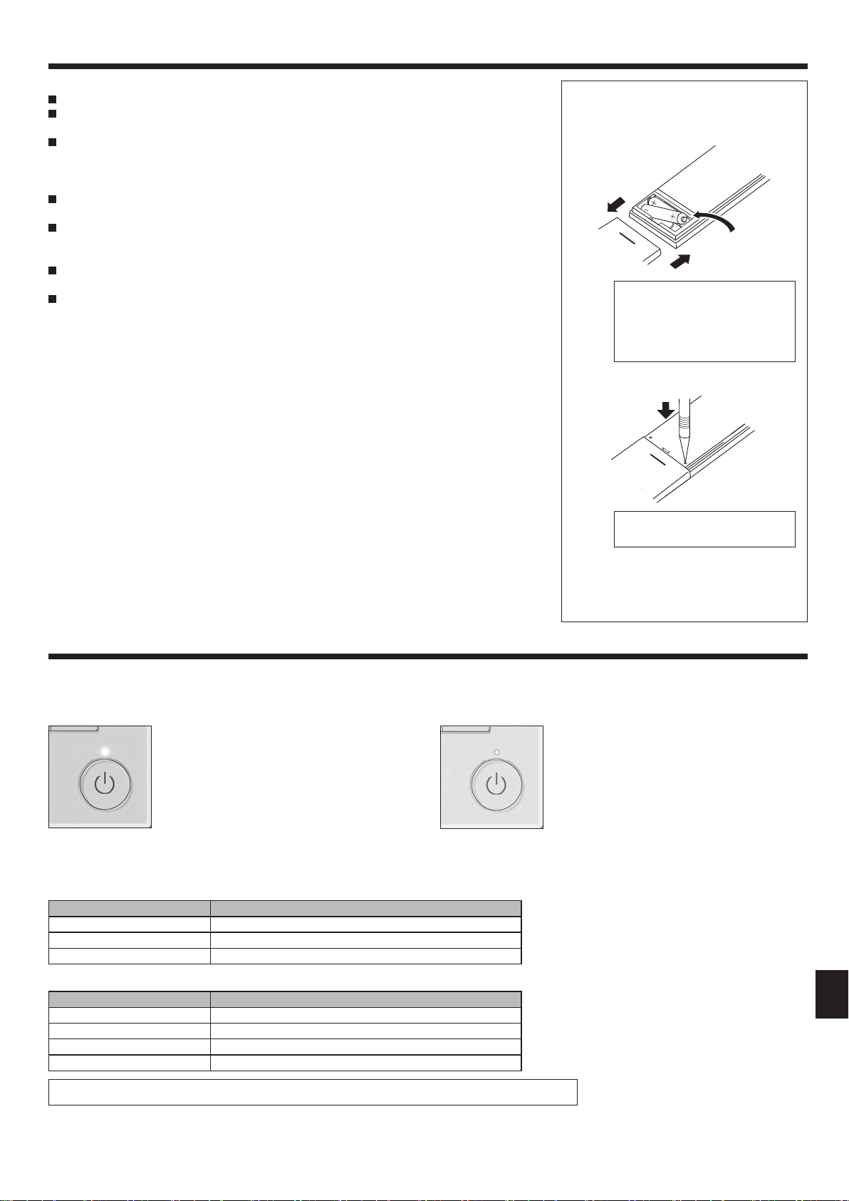
Wireless Remote-Controller (Optional parts)
Set Temperature buttons
Transmission area
Not available
Remote controller display
Battery replacement indicator
OFF/ON button
Mode button (Changes operation mode)
Air ow button (Changes up/down air ow direction)
Timer ON button
Timer OFF button
Weekly timer ON/OFF button
Set Time button (Sets the time)
Operation mode
Cool Dry
Fan
Heat
* The initial setting is necessary.
Refer to Installation manual.
(not available)
Auto
(single set
point)
Auto*
(dual set
point)
Fan Speed button (Changes fan speed)
i-see button
Menu button
SET/SEND button
CANCEL button
Up/Down buttons
Reset button
Not available
Appears when a non-supported function is selected.
Battery replacement indicator
Appears when the remaining battery
power is low.
Temperature setting
The units of temperature can be changed. For
details, refer to the Installation manual.
Vane setting
Step 1 Step 2 Step 3 Step 4 Step 5 Swing Auto
en
4
Fan speed setting
Auto
3D i-see sensor (Air distribution)
Default Direct Indirect
When Direct or Indirect
is selected, the vane
setting is set to “Auto”.
2. Parts Names
Notes (Only for wireless remote controller):
When using the wireless remote controller, point it towards the receiver on the indoor unit.
If the remote controller is operated within approximately 2 minutes after power is supplied to the
indoor unit, the indoor unit may beep twice as the unit is performing the initial automatic check.
The indoor unit beeps to confirm that the signal transmitted from the remote controller has
been received. Signals can be received up to approximately 7 meters in a direct line from the
indoor unit in an area 45° to the left and right of the unit. However, illumination such as fluorescent lights and strong light can affect the ability of the indoor unit to receive signals.
If the operation lamp near the receiver on the indoor unit is blinking, the unit needs to be in-
spected. Consult your dealer for service.
Handle the remote controller carefully! Do not drop the remote controller or subject it to strong
shocks. In addition, do not get the remote controller wet or leave it in a location with high humidity.
To avoid misplacing the remote controller, install the holder included with the remote controller
on a wall and be sure to always place the remote controller in the holder after use.
If the indoor unit beeps 4 times when you are using the wireless remote controller, switch the
auto mode setting to the AUTO (single set point) mode or AUTO (dual set point) mode.
For details, refer to the included Notice (A5 sheet) or the Installation Manual.
Battery installation/replacement
1. Remove the top cover, insert two LR6 AA
batteries, and then install the top cover.
1
2
Top cover
3
Two LR6 AA batteries
Insert the negative (–) end of
each battery first. Install the
batteries in the correct directions
(+, –)!
2. Press the Reset button.
Press the Reset button with an
object that has a narrow end.
After battery installation/replacement,
please set clock.
Without setting clock, you cannot use a
part of function of remote controller.
3. Operation
■
About the operation method, refer to the operation manual that comes with each remote controller.
3.1. Turning ON/OFF
[ON] [OFF]
Press the [ON/OFF] button.
The ON/OFF lamp will light up in
green, and the operation will start.
When “LED lighting” is set to “No,” the
ON/OFF lamp will not light up.
Note:
Even if you press the ON/OFF button immediately after shutting down the operation is progress, the air conditioner will not start for about 3 minutes.
This is to prevent the internal components from being damaged.
■
Operation status memory
Remote controller setting
Operation mode Operation mode before the power was turned off
Preset temperature Preset temperature before the power was turned off
Fan speed Fan speed before the power was turned off
Press the [ON/OFF] button again.
The ON/OFF lamp will come off,
and the operation will stop.
■
Settable preset temperature range
Operation mode Preset temperature range
Cool/Dry 19 ~ 30 ºC
Heat 17 ~ 28 ºC
Auto 19 ~ 28 ºC
Fan/Ventilation Not settable
The settable temperature range varies with the model of outdoor units and remote controller.
en
5
3. Operation
3.2. Mode Selection
Each pressing of the [F1] button cycles
Fri
Room
Cool
Mode Temp. Fan
F1 F2 F3 F4
AutoSet temp.
through the following operation modes.
Select the desired operation mode.
Cool Dry Fan
Auto Heat
• Operation modes that are not available to
the connected outdoor unit models will not
appear on the display.
What the blinking mode icon means
The mode icon will blink when other indoor units in the same
refrigerant system (connected to the same outdoor unit) are already
operated in a different mode. In this case, the rest of the unit in the
same group can only be operated in the same mode.
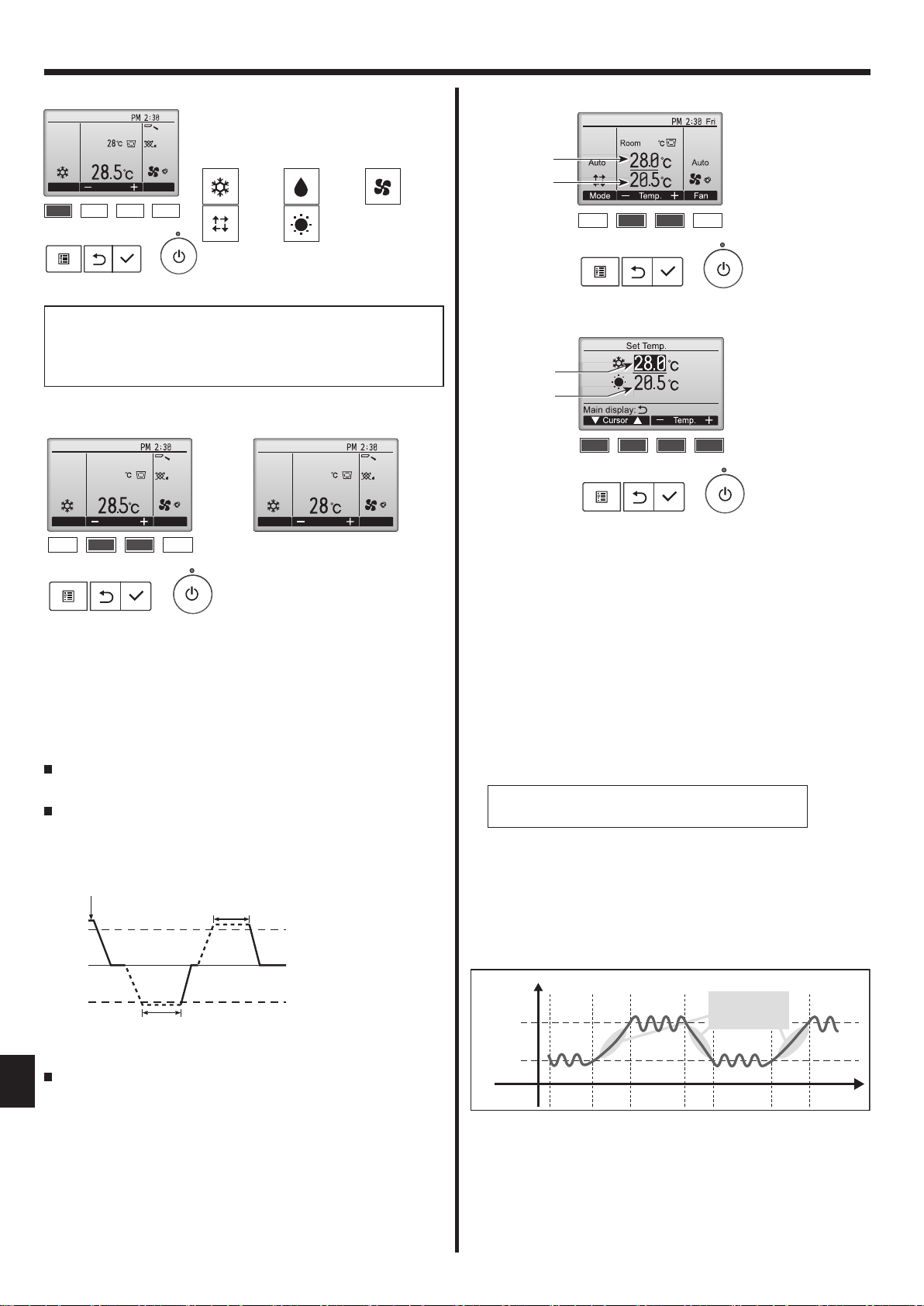
3.3. Temperature setting
<Cool, Dry, Heat, and Auto (Single set point)>
Fri
Room
Cool
Mode Temp. Fan
F1 F2 F3 F4
28.5
AutoSet temp.
(Centigrade in 1-degree increments)
Press the [F2] button to decrease the preset temperature, and press the
[F3] button to increase.
• Refer to the table on 3.1. for the settable temperature range for different
operation modes.
• Preset temperature range cannot be set for Fan/Ventilation operation.
• Preset temperature will be displayed either in Centigrade in 0.5- or
1-degree increments, or in Fahrenheit, depending on the indoor unit
model and the display mode setting on the remote controller.
Automatic operation (Single set point)
According to a set temperature, cooling operation starts if the room
temperature is too hot and heating operation starts if the room
temperature is too cold.
During automatic operation, if the room temperature changes and
remains 1.5 °C or more above the set temperature for 3 minutes, the
air conditioner switches to cool mode. In the same way, if the room
temperature remains 1.5 °C or more below the set temperature for
3 minutes, the air conditioner switches to heat mode.
Cool mode
3 minutes (switches
from cooling to heating)
Because the room temperature is automatically adjusted in order to
en
maintain a fixed effective temperature, cooling operation is performed
3 minutes (switches
from heating to cooling)
a few degrees warmer and heating operation is performed a few
degrees cooler than the set room temperature once the temperature is
reached (automatic energy-saving operation).
Room
Cool
Mode Temp. Fan
28
Example display
Set temperature +1.5°C
Set temperature
Set temperature -1.5°C
<Auto (dual set point) mode>
Preset temperature
for cooling
Preset temperature
for heating
F1 F2 F3 F4
26.5
1 The current preset temperatures will appear. Press the [F2] or [F3]
button to display the Settings screen.
Preset temperature
for cooling
Preset temperature
for heating
Fri
AutoSet temp.
F1 F2 F3 F4
2 Press the [F1] or [F2] button to move the cursor to the desired
temperature setting (cooling or heating).
Press the [F3] button to decrease the selected temperature, and [F4]
to increase.
• Refer to the table on 3.1. for the settable temperature range for
different operation modes.
•
The preset temperature settings for cooling and heating in the “Auto”
(dual set point) mode are also used by the “Cool”/“Dry” and “Heat”
modes.
• The preset temperatures for cooling and heating in the “Auto” (dual
set point) mode must meet the conditions below:
• Preset cooling temperature is higher than preset heating temperature.
• The minimum temperature difference requirement between cooling and
heating preset temperatures (varies with the models of indoor units
connected) is met.
* If preset temperatures are set in a way that does not meet the minimum
temperature difference requirement, both preset temperatures will
automatically be changed within the allowable setting ranges.
Navigating through the screens
• To return to the Main screen ...... [RETURN] button
Automatic operation (Dual set point)
When the operation mode is set to the “Auto” (dual set point) mode,
two preset temperatures (one each for cooling and heating) can be
set. Depending on the room temperature, indoor unit will automatically
operate in either the “Cool” or “Heat” mode and keep the room
temperature within the preset range.
The graph below shows the operation pattern of indoor unit operated in
the
“
Auto” (dual set point) mode.
Operation pattern during Auto (dual set point) mode
The room temperature
Preset temp.
(COOL)
Preset temp.
(HEAT)
changes corresponding
to the change in the
outside temperature.
Room
temperature
HEAT COOL HEAT COOL
6
3. Operation
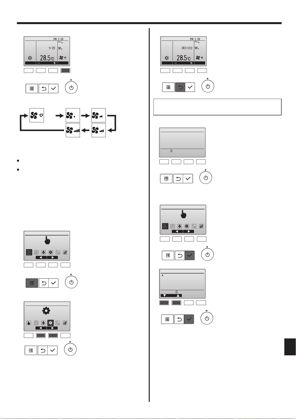
3.4. Fan speed setting
Fri
Room
Cool
Mode Temp. Fan
F1 F2 F3 F4
28.5
AutoSet temp.
Press the [F4] button to go through the fan speeds in the following order.
Auto
•
The available fan speeds depend on the models of connected indoor units.
Note:
The number of available fan speeds depends on the type of unit
connected. Note also that some units do not provide an “Auto” setting.
In the following cases, the actual fan speed generated by the unit will differ
from the speed shown the remote controller display.
1. While the display is showing “STAND BY” or “DEFROST”.
2. When the temperature of the heat exchanger is low in the heat mode.
(e.g. immediately after heat operation starts)
In HEAT mode, when room temperature is higher than the temperature setting.
3.
4. In COOL mode, when room temperature is lower than the temperature
setting.
5. When the unit is in DRY mode.
3.5. Airflow direction setting
3.5.1. Navigating through the Main menu
<Accessing the Main menu>
Main Main menu
Operation
Press the [MENU] button on the
Main display.
The Main menu will appear.
<Exiting the Main menu screen>
Room
Cool
Mode Temp. Fan
F1 F2 F3 F4
AutoSet temp.
Fri
Press the [RETURN] button to exit
the Main menu and return to the
Main display.
If no buttons are touched for 10 minutes, the screen will automatically
return to the Main display. Any settings that have not been saved will
be lost.
<Display of unsupported functions>
Title
Not available
Unsupported function
Return:
F1 F2 F3 F4
The message at left will appear if
the user selects a function not supported by the corresponding indoor
unit model.
3.5.2. Vane·Vent. (Lossnay)
<Accessing the menu>
Main Main menu
Operation
F1 F2 F3 F4
Select “Operation” from the Main
menu (refer to 3.5.1), and press the
[SELECT] button.
F1 F2 F3 F4
<Item selection>
Main Main menu
Initial setting
F1 F2 F3 F4
Press [F2] to move the cursor left.
Press [F3] to move the cursor right.
Operation
Vane·Louver·Vent. (Lossnay)
High power
Comfort
Main menu:
Cursor
F1 F2 F3 F4
Select “Vane·Louver·Vent.
(Lossnay)” from the Operation
menu, and press the [SELECT]
button.
en
7
3. Operation
<Vane setting>
Swing Off
F1 F2 F3 F4
Room
Cool
Mode Temp. Fan
<Vent. setting>
F1 F2 F3 F4
28.5
Vent.Vane
Low
Vent.
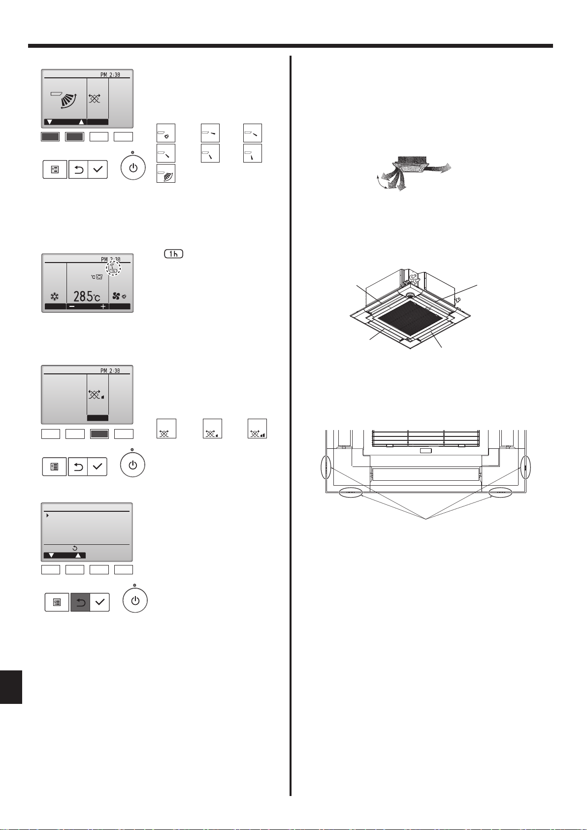
<How to set the xed up/down air direction>
Fri
Press the [F1] or [F2] button to go
through the vane setting options:
“Auto”, “Step 1”, “Step 2”, “Step 3”,
“Step 4”, “Step 5” and “Swing”.
Select the desired setting.
Auto
Swing
Auto
Swing
Step 1 Step 2
Step 4Step 3
Step 5
Note:
● This function cannot be set depending on the outdoor unit to be
connected.
• For PLFY-VEM series, only the particular outlet can be xed to certain
direction with the procedures below. Once xed, only the set outlet is
xed every time air conditioner is turned on. (Other outlets follow UP/
DOWN air direction setting of remote controller.)
Horizontal airflow
Select “Swing” to move the vanes
up and down automatically.
When set to “Step 1” through “Step
5”, the vane will be xed at the selected angle.
Fri
• under the vane setting icon
This icon will appear when the
vane is set to “Step 5” and the
AutoSet temp.
fan operates at low speed during
Remote controller setting
The airflow direction of this
outlet is controlled by the airflow
direction setting of remote
controller.
Outlet No. 2
Fixed
The airflow direction of this outlet is fixed
in particular direction.
* When it is cold because of direct
airflow, the airflow direction can be
fixed horizontally to avoid direct airflow.
Outlet No. 3
cooling or dry operation (depends
on the model).
The icon will go off in an hour, and
the vane setting will automatically
change.
Outlet No. 1
Fri
Press the [F3] button to go through
the ventilation setting options in the
order of “Off”, “Low”, and “High”.
* Settable only when LOSSNAY unit
is connected.
Off Low High
Off Low High
Note:
The outlet No. is indicated by the number of grooves on both
ends of each air outlet. Set the air direction while checking the
information shown on the remote controller display.
Outlet No. 4
• The fan on some models of indoor
units may be interlocked with certain models of ventilation units.
<Returning to the Main menu>
Operation
Vane·Louver·Vent. (Lossnay)
High power
Comfort
Main menu:
Cursor
F1 F2 F3 F4
Note:
During swing operation, the directional indication on the screen
●
Press the [RETURN] button to go
back to the Main menu.
does not change in sync with the directional vanes on the unit.
● Available directions depend on the type of unit connected.
In the following cases, the actual air direction will differ from the
●
direction indicated on the remote controller display.
1. While the display is in “STAND BY” or “DEFROST” states.
en
2. Immediately after starting heat mode (while the system is wait-
ing for the mode change to take effect).
3. In heat mode, when room temperature is higher than the tem-
perature setting.
Air outlet identification marks
8
3. Operation
■
Manual vane angle (Wired remote controller)
Operation
Vane·Louver·Vent. (Lossnay)
High power
Comfort
Main menu:
Cursor
F1 F2 F3 F4
Comfort
Manual vane angle
3D i-See sensor
Setting display:
Cursor
F1 F2 F3 F4
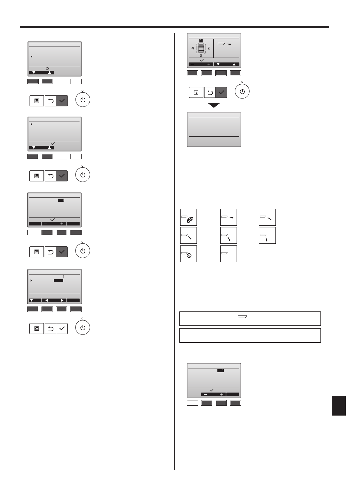
Manual vane angle
M-NET address
1 Select “Comfort” from the
Operation menu, and press the
[SELECT] button.
2 Select “Manual vane angle” with
the [F1] or [F2] button, and press
the [SELECT] button.
3 Select the “M-NET address” for
the units to whose vanes are
to be fixed, with the [F2] or [F3]
Identify unit Check button
Input display:
Cur. Address Check
button, and press the [SELECT]
button.
Press the [F4] button to confirm
the unit.
F1 F2 F3 F4
The vane of only the target indoor
unit is pointing downward.
Manual vane angle
5 The current vane setting will
appear.
Select the desired outlets from
Select:
Outlet Angle
1 through 4 with the [F1] or [F2]
button.
• Outlet: “1”, “2”, “3”, “4” and “1, 2,
F1 F2 F3 F4
3, 4, (all outlets)”
Press the [F3] or [F4] button to
go through the option in the order
of “No setting (reset)”, “Step 1”,
“Step 2”, “Step 3”, “Step 4”, “Step
Manual vane angle
Setting
5” and “Draft reduction*”.
Select the desired setting.
* Draft reduction
The airflow direction for this
setting is more horizontal than
the airflow direction for the “Step
1” setting in order to reduce a
drafty feeling. The draft reduction
can be set for only 1 vane.
Note:
Do not set the draft reduction in an environment with high humidity.
Otherwise, condensation may form and drip.
■
Vane setting
No setting
Step 3
Step 1 Step 2
Step 5Step 4
Manual vane angle
M-NET address
Vane
Input display:Angle button
Cur. Angle
F1 F2 F3 F4
4-way /2-way
Cursor
4 Select “Vane” with the [F1]
button.
Select “4-way” or “2-way” with the
[F2] or [F3] button, and press the
[F4] button.
Draft
reduction*
All outlets
Press the [SELECT] button to save the settings.
A screen will appear that indicates the setting information is being transmitted.
The setting changes will be made to the selected outlet.
The screen will automatically return to the one shown above (step 5)
when the transmission is completed.
Make the settings for other outlets, following the same procedures.
If all outlets are selected,
will be displayed the next time
the unit goes into operation.
Navigating through the screens
• To return to the previous screen .......... [RETURN] button
■ Conrmation procedure of the target unit
Manual vane angle
M-NET address
Identify unit Check button
Input display:
Address Check
F1 F2 F3 F4
1 Select the “M-NET address” for
the units to whose vanes are
to be fixed, with the [F2] or [F3]
button. Press the [F4] button to
conrm the unit.
en
9
3. Operation
Manual vane angle
M-NET address
Function setting for unit
with vane fully open.
Return:
2 After pressing the [F4] button,
wait approximately 15 seconds,
and then check the current state
of the air conditioner.
→ The vane is pointing
downward. → This air conditioner
is displayed on the remote
F1 F2 F3 F4
controller.
→ All outlets are closed. →
Press the [RETURN] button and
continue the operation from the
beginning.
Manual vane angle
→ The messages shown to the
left are displayed. → The target
No communication
Check Unit state.
Return:
device does not exist at this
refrigerant address.
• Press the [RETURN] button to
return to the initial screen.
F1 F2 F3 F4
3 Change the “M-NET address” to
the next number.
• Refer to step 1 to change the
“M-NET address” and continue
with the confirmation.
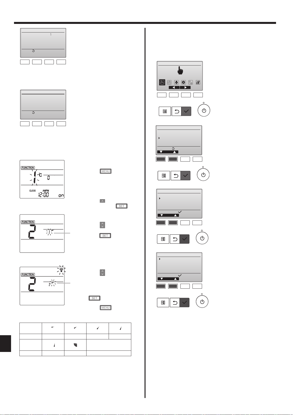
■ Manual vane angle (Wireless remote controller)
1 Going to the Manual vane setting
mode
Press the
(Start this operation from the
status of remote controller
display turned off.)
“FUNCTION” is lighted and “1”
blinks. (Fig. 3-1)
Fig. 3-1
Press the button to select “2”,
and then press the button.
2 Selecting the vane number (Fig.
3-2)
Press the buttons to select
the vane number A, and then
A
press the button.
button.
3.6. 3D i-see Sensor setting
Note:
This function cannot be set depending on the outdoor unit to be
connected.
3.6.1. 3D i-see Sensor setting
Main Main menu
Operation
F1 F2 F3 F4
Operation
Vane·Louver·Vent. (Lossnay)
High power
Comfort
Main menu:
Cursor
F1 F2 F3 F4
Comfort
Manual vane angle
3D i-See sensor
Setting display:
Cursor
F1 F2 F3 F4
1 Select “Operation” from the Main
menu, and press the [SELECT]
button.
2 Select “Comfort” from the
Operation menu, and press the
[SELECT] button.
3 Select “3D i-See sensor” with the
[F1] or [F2] button, and press the
[SELECT] button.
en
Fig. 3-2
3 Setting the vane angle (Fig. 3-3)
Press the buttons to select
the vane angle B.
Point the wireless remote
B
controller toward the receiver on
the indoor unit, and then press
the button.
Fig. 3-3
4 Press the button to
complete the settings.
Display
Setting Step 1 Step 2 Step 3 Step 4
Display
No display
Setting Step 5 No setting Draft reduction*
* The draft reduction can be set for only 1 vane.
The setting is enabled only for the last vane that was set.
3D i-See sensor
Air distribution
Energy saving option
Seasonal airflow
Setting display:
Cursor
F1 F2 F3 F4
4 Select the desired menu with the
[F1] or [F2] button, and press the
[SELECT] button.
• Air distribution
Select the airflow direction
control method when the airflow
direction is set to “Auto”.
• Energy saving option
Operates the energy-save mode
according to whether persons are
detected in the room by the 3D
i-see Sensor.
• Seasonal airflow
When the thermostat turns off,
the fan and the vanes operate
according to the control settings.
10
 Loading...