

Mitsubishi Electric city multi PKFY-P-VKM-E, city multi PLFY-P-VCM-E2, city multi PCFY-P-VKM-E Operation Manual
Air-Conditioners For Building Application
INDOOR UNIT
PKFY-P·VKM-E
PLFY-P·VCM-E2
PCFY-P·VKM-E
OPERATION MANUAL
For safe and correct use, please read this operation manual thoroughly before operating the air-conditioner unit.
FOR USER
English (GB)
BEDIENUNGSHANDBUCH
Zum sicheren und einwandfreien Gebrauch der Klimaanlage dieses Bedienungshandbuch vor Inbetriebnahme
gründlich durchlesen.
FÜR BENUTZER
Deutsch (D)
MANUEL D’UTILISATION
Pour une utilisation correcte sans risques, veuillez lire le manuel d’utilisation en entier avant de vous servir du
climatiseur.
POUR L’UTILISATEUR
Français (F)
BEDIENINGSHANDLEIDING
Voor een veilig en juist gebruik moet u deze bedieningshandleiding grondig doorlezen voordat u de
airconditioner gebruikt.
VOOR DE GEBRUIKER
Nederlands (NL)
MANUAL DE INSTRUCCIONES
Lea este manual de instrucciones hasta el final antes de poner en marcha la unidad de aire acondicionado
para garantizar un uso seguro y correcto.
PARA EL USUARIO
Español (E)
ISTRUZIONI DI FUNZIONAMENTO
Leggere attentamente questi istruzioni di funzionamento prima di avviare l’unità, per un uso corretto e sicuro
della stessa.
PER L’UTENTE
Italiano (I)
EΓXEIPIΔIO OΔHΓIΩN XPHΣEΩΣ
Για ασφάλεια και σωστή χρήση, παρακαλείστε διαβάσετε προσεχτικά αυτό το εγχειρίδιο χρήσεως πριν θέησετε
σε λειτουργία τη μονάδα κλιματισμού.
ΓΙΑ ΤΟΝ ΧΡΗΣΤΗ
Ελληνικά (GR)
MANUAL DE OPERAÇÃO
Para segurança e utilização correctas, leia atentamente o manual de operação antes de pôr a funcionar a
unidade de ar condicionado.
PARA O UTILIZADOR
Português (P)
Işletme Elkitabı
Emniyetli ve doğru biçimde nasıl kullanılacağını öğrenmek için lütfen klima cihazını işletmeden önce bu
elkitabını dikkatle okuyunuz.
KULLANICI İÇİN
Türkçe (TR)
РУКОВОДСТВО ПО ЭКСПЛУАТАЦИИ
Для обеспечения правильного и безопасного использования следует ознакомиться с инструкциями,
указанными в данном руководстве по эксплуатации, тщательным образом до того, как приступать к
использованию кондиционера.
ДЛЯ ПОЛЬЗОВАТЕЛЯ
Русский (RU)
2
GB
Contents
1. Safety Precautions
Before installing the unit, make sure you read all the
“Safety Precautions”.
The “Safety Precautions” provide very important
points regarding safety. Make sure you follow them.
Please report to or take consent by the supply
authority before connection to the system.
• Do not touch the upper air outlet vane or the lower air outlet
damper during operation. Otherwise, condensation may form and
the unit may stop operating.
Disposing of the unit
When you need to dispose of the unit, consult your dealer.
Caution:
• Do not use any sharp object to push the buttons, as this may
damage the remote controller.
•
Never block or cover the indoor or outdoor unit’s air inlets or outlets
.
• Never wipe the remote controller with benzene, thinner chemical
rags, etc.
• Do not operate the unit for a long time in high humidity, e.g.
leaving a door or window open. In the cool mode, if the unit is
operated in a room with high humidity (80% RH or more) for a
long time, water condensed in the air conditioner may drop and
wet or damage furniture, etc.
• Young children must be supervised to ensure that they do not
play with the air conditioner.
• If the refrigeration gas blows out or leaks, stop the operation of
the air conditioner, thoroughly ventilate the room, and contact
your dealer.
• This appliance is not intended for use by persons (including
children) with reduced physical, sensory or mental capabilities,
or lack of experience and knowledge, unless they have been
given supervision or instruction concerning use of the appliance
by a person responsible for their safety.
• When installing or relocating, or servicing the air conditioner, use
only the specified refrigerant (R410A) to charge the refrigerant
lines. Do not mix it with any other refrigerant and do not allow air
to remain in the lines.
If air is mixed with the refrigerant, then it can be the cause of
abnormal high pressure in the refrigerant line, and may result in
an explosion and other hazards. The use of any refrigerant other
than that specified for the system will cause mechanical failure
or system malfunction or unit breakdown. In the worst case, this
could lead to a serious impediment to securing product safety.
Warning:
• These appliances are not accessible to the general public.
• The unit must not be installed by the user. Ask the dealer or an
authorized company to install the unit. If the unit is installed
improperly, water leakage, electric shock or fire may result.
• Do not stand on, or place any items on the unit.
• Do not splash water over the unit and do not touch the unit with
wet hands. An electric shock may result.
• Do not spray combustible gas close to the unit. Fire may result.
• Do not place a gas heater or any other open-flame appliance
where it will be exposed to the air discharged from the unit.
Incomplete combustion may result.
• Do not remove the front panel or the fan guard from the outdoor
unit when it is running.
• Never repair the unit or transfer it to another site by yourself.
• When you notice exceptionally abnormal noise or vibration, stop
operation, turn off the power switch, and contact your dealer.
• Never insert fingers, sticks etc. into the air inlets or outlets.
• If you detect odd smells, stop using the unit, turn off the power
switch and consult your dealer. Otherwise, a breakdown, electric
shock or fire may result.
• This air conditioner is NOT intended for use by children or infirm
persons without supervision.
Symbols used in the text
Warning:
Describes precautions that should be observed to prevent danger
of injury or death to the user.
Caution:
Describes precautions that should be observed to prevent damage
to the unit.
Symbols used in the illustrations
: Indicates a part which must be grounded.
1. Safety Precautions ................................................................2
2. Parts Names ..........................................................................3
3. Screen Configuration .............................................................6
4. Setting the Day of the Week and Time ..................................6
5. Operation ...............................................................................6
6. Timer .....................................................................................9
7. Other Functions ...................................................................12
8. Function Selection ...............................................................13
9. Emergency Operation for Wireless Remote-controller ........17
10. Care and Cleaning ..............................................................17
11. Trouble shooting ..................................................................19
12. Specifications ......................................................................21
Note:
The phrase “Wired remote controller” in this operation manual refers to the PAR-21MAA.
If you need any information for the other remote controller, please refer to the instruction book included in this box.
This symbol mark is for EU countries only.
This symbol mark is according to the directive 2002/96/EC Article 10 Information for users and Annex IV, and/or to the
directive 2006/66/EC Article 20 Information for end-users and Annex II.
Your MITSUBISHI ELECTRIC product is designed and manufactured with high quality materials and components which can be
recycled and/or reused. This symbol means that electrical and electronic equipment, batteries and accumulators, at their end-oflife, should be disposed of separately from your household waste. If a chemical symbol is printed beneath the symbol (Fig. 1), this
chemical symbol means that the battery or accumulator contains a heavy metal at a certain concentration.
This will be indicated as follows: Hg: mercury (0,0005%), Cd: cadmium (0,002%), Pb: lead (0,004%)
In the European Union there are separate collection systems for used electrical and electronic products, batteries and accumulators.
Please, dispose of this equipment, batteries and accumulators correctly at your local community waste collection/recycling centre.
Please, help us to conserve the environment we live in!
Note
Fig.1
3
GB
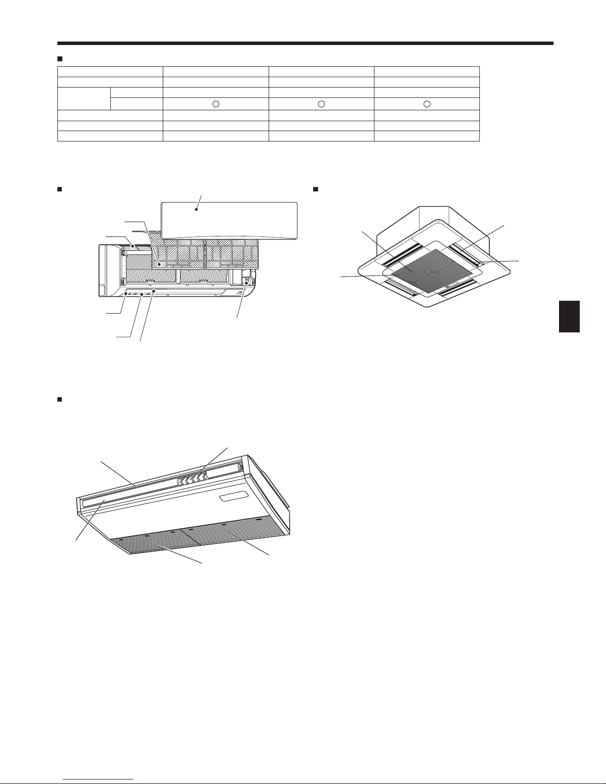
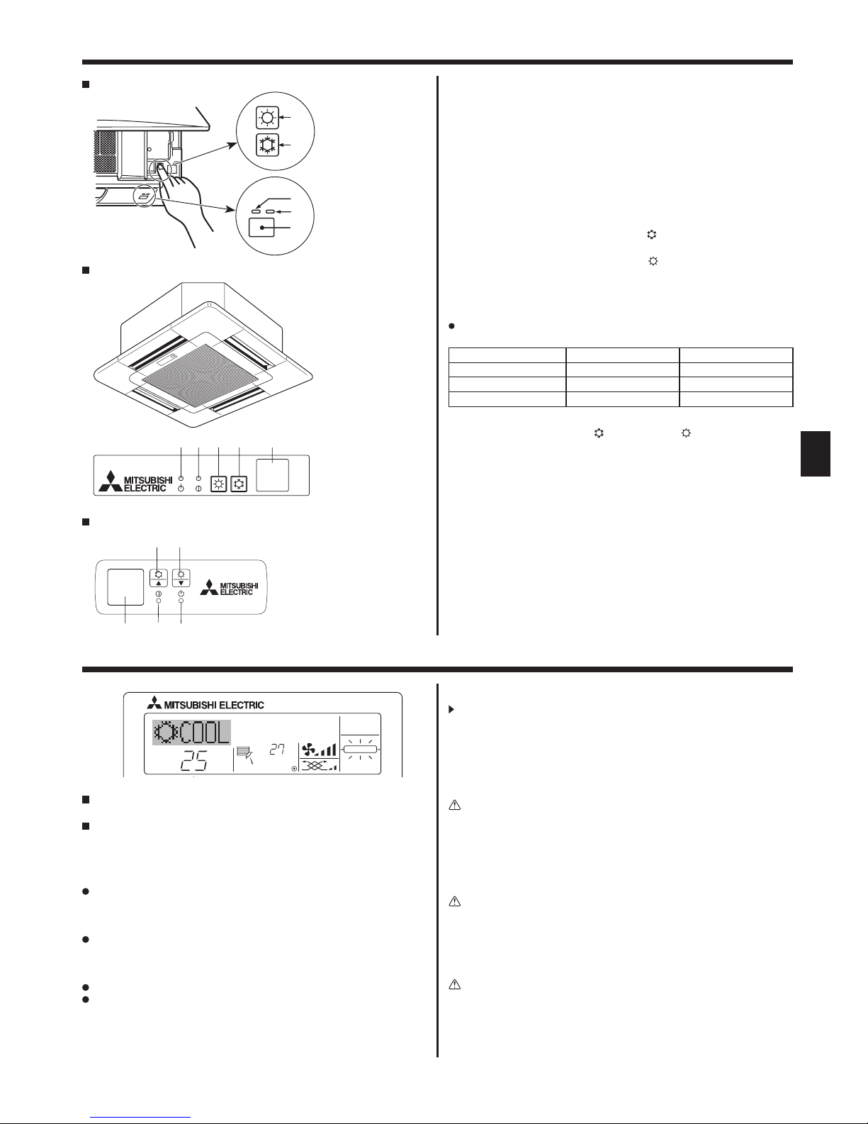
2. Parts Names
PKFY-P·VKM-E
Wall Mounted
Indoor Unit
PKFY-P·VKM-E PLFY-P·VCM-E2 PCFY-P·VKM-E
Fan speed 2 speed 3 speed 4 speed+ Auto*
Vane
Steps 4 steps 4 steps 5 steps
Auto Swing
Louver Manual ― Manual
Filter Normal Long-life Long-life
Filter cleaning indication 100 hr 2,500 hr 2,500 hr
PLFY-P·VCM-E2
4-way Ceiling Cassette
Filter
Air
intake
Vane
Air outlet
* This operation is available only using the remote controller
that is able to set its Fan speed setting "Auto".
PCFY-P·VKM-E
Ceiling Suspended
Air outlet
Louver
Vane
Air intake
Filter
(Inside of Air intake)
Emergency operation switch
Front grille
Filter
Air inlet
Air outlet
Louver
Van e
4
GB
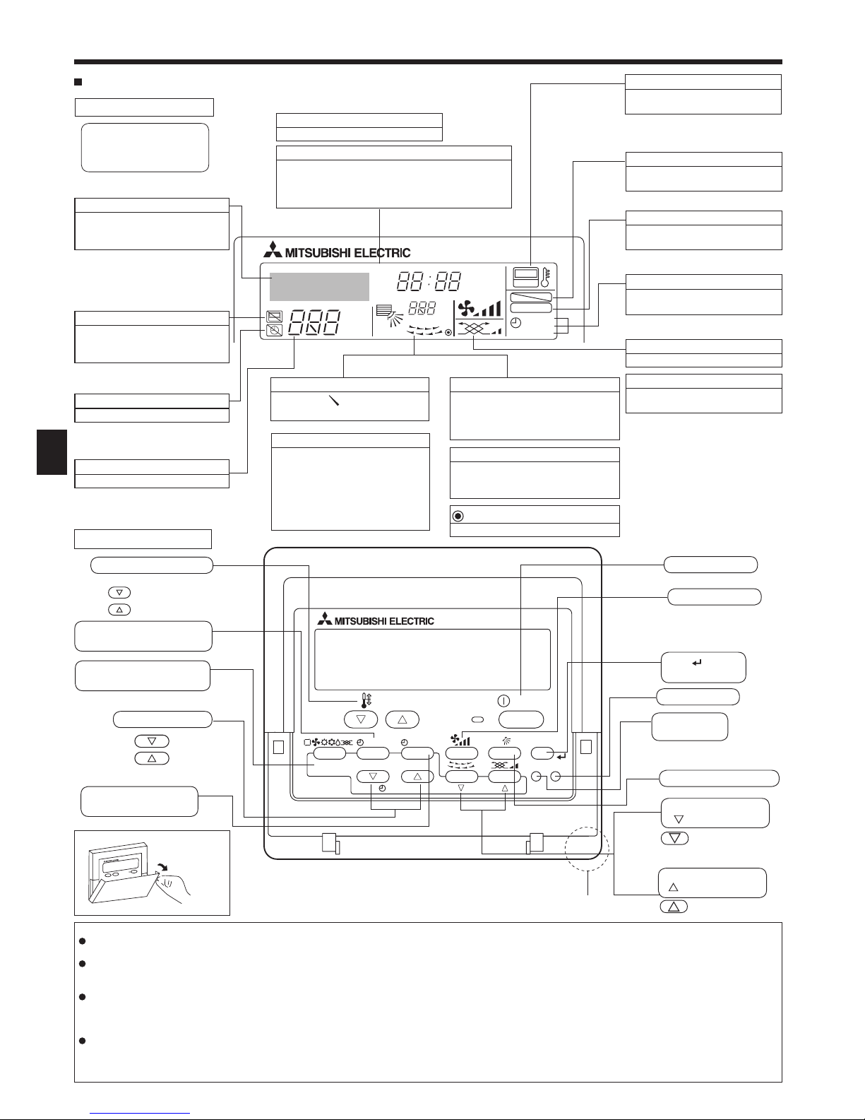
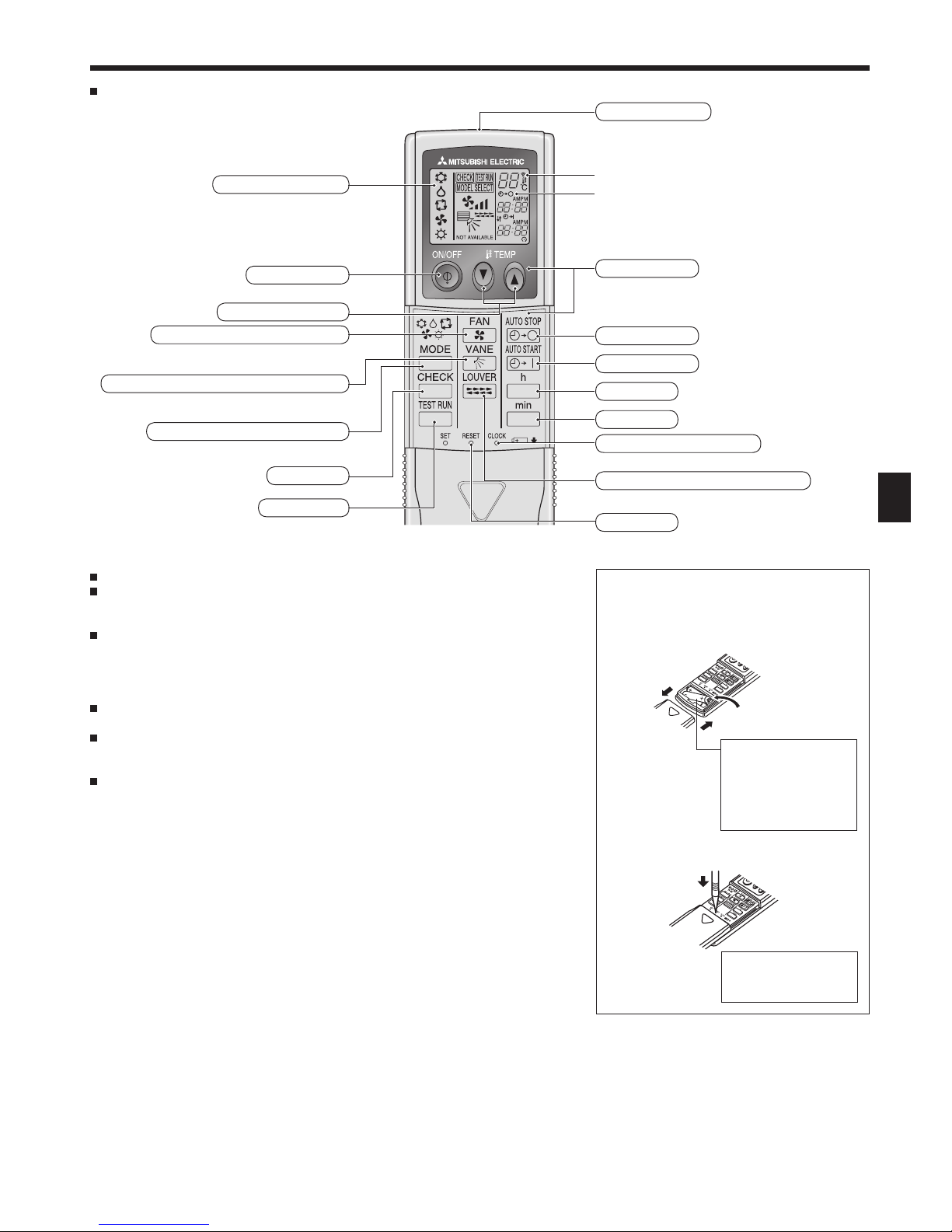
PAR-21MAA
ON/OFF
FILTER
CHECK
OPERATION
CLEAR
TEST
TEMP.
MENU
BACK DAY
MONITOR/SET
CLOCK
ON/OFF
°F°C
°F°C
ERROR CODE
AFTER
TIMER
TIME SUN MON TUE WED THU FRI SAT
ON
OFF
Hr
AFTER
FILTER
FUNCTION
ONLY1Hr.
WEEKLY
SIMPLE
AUTO OFF
Operation Section
Down
Up
Back
Ahead
Opening the
cover
To preceding
operation number.
To next operation
number.
2. Parts Names
Built-in temperature sensor
Display Section
Identifies the current operation
Shows the operation mode, etc.
* Multi language display is
supported.
“Centrally Controlled” indicator
Indicates that operation of the
remote controller has been
prohibited by a master controller.
“Timer is Off” indicator
Indicates that the timer is off.
“One Hour Only” indicator
Displayed if the airflow is set to Low
and downward during COOL or DRY
operation mode. (Operation varies
according to model.)
The indicator goes off after one hour
when the airflow up/down direction
also changes.
Temperature Setting
Shows the target temperature.
Airflow up/down direction indicator
The indicator shows the direction
of the outcoming airflow.
Day-of-Week
Shows the current day of the week.
Room Temperature display
Shows the room temperature. The room
temperature display range is 8 – 39 °C.
The display blinks if the temperature is
less than 8 °C or 39 °C or more.
Time/Timer Display
Shows the current time, unless the simple or Auto Off
timer is set.
If the simple or Auto Off timer is set, shows the time
remaining.
Louver display
Indicates the action of the swing louver.
Does not appear if the louver is
stationary.
(Power On indicator)
Indicates that the power is on.
Fan Speed indicator
Shows the selected fan speed.
Ventilation indicator
Appears when the unit is running in
Ventilation mode.
“Locking function” indicator
Indicates that remote controller
buttons have been locked.
“Clean the filter” indicator
Comes on when it is time to clean
the filter.
Timer indicators
The indicator comes on if the
corresponding timer is set.
For purposes of this explanation,
all parts of the display are shown
as lit. During actual operation,
only the relevant items will be lit.
Note:
“PLEASE WAIT” message
This message is displayed for approximately 3 minutes when power is supplied to the indoor unit or when the unit is recovering from a power failure.
Operation mode flashing display
When multiple indoor units are connected to a single outdoor unit and an operation mode is selected for one indoor unit that is different from the
current operation mode of another indoor unit, the operation mode display flashes. Select the same operation mode of the other indoor unit.
“NOT AVAILABLE” message
This message is displayed if a button is pressed to operate a function that the indoor unit does not have.
When the same remote controller is used to operate multiple indoor units, this message is displayed if the main indoor unit is not equipped with
the selected function.
Room temperature display
The indoor unit temperature sensors or the remote controller temperature sensor can be selected to measure the room temperature. The indoor
unit temperature sensors are the initial setting. When the indoor unit temperature sensors are selected to measure the room temperature, the
room temperature measured at the main indoor unit is displayed on the remote controller that operates multiple indoor units.
Temperature set buttons
Timer Menu button
(Timer monitor/Timer set button)
Operation mode button
(Back button)
Set Time buttons
Timer On/Off button
(Set Day button)
ON/OFF button
Fan Speed button
Filter button
(<Enter> button)
Test Run button
Check button
(Clear button)
Airflow up/down button
Louver button
(
Operation button)
Ventilation button
(
Operation button)
Wired Remote-Controller (Optional parts)
“Sensor” indicator
Displayed when the remote controller
sensor is used.
5
GB
Wireless Remote-Controller (Optional parts)
2. Parts Names
Transmission indicator
Timer indicator
When using the wireless remote controller, point it towards the receiver on the indoor unit.
If the remote controller is operated within approximately 2 minutes after power is supplied
to the indoor unit, the indoor unit may beep twice as the unit is performing the initial
automatic check.
The indoor unit beeps to confirm that the signal transmitted from the remote controller has
been received. Signals can be received up to approximately 7 meters in a direct line from
the indoor unit in an area 45° to the left and right of the unit. However, illumination such
as fluorescent lights and strong light can affect the ability of the indoor unit to receive
signals.
If the operation lamp near the receiver on the indoor unit is flashing, the unit needs to be
inspected. Consult your dealer for service.
Handle the remote controller carefully! Do not drop the remote controller or subject it to
strong shocks. In addition, do not get the remote controller wet or leave it in a location
with high humidity.
To avoid misplacing the remote controller, install the holder included with the remote
controller on a wall and be sure to always place the remote controller in the holder after
use.
* For explanation purposes, all of the items
that appear in the display are shown.
* All items are displayed when the Reset
button is pressed.
Remote controller display
ON/OFF button
Temperature set buttons
Fan Speed button (Changes fan speed)
Airflow button (Changes airflow up/down direction)
Mode button (Changes operation mode)
Check button
Test Run button
Transmission area
Operation areas
Timer Off button
Timer On button
Hour button
Minute button
Set Time button (Sets the time)
Louver button (Changes left/right direction)
Reset button
Battery installation/replacement
1. Remove the top cover, insert two AAA
batteries, and then install the top cover.
2. Press the Reset button.
1
2
3
Top cover
Two AAA batteries
Insert the negative
(–) end of each
battery first. Install the
batteries in the correct
directions (+, –)!
Press the Reset button
with an object that has
a narrow end.
6
GB
Note:
The day and time will not appear if clock use has been disabled at Function
Selection of remote controller.
°C
°C
TIME SUN
PAR-21MAA
ON/OFF
FILTER
CHECK
OPERATION
CLEAR
TEST
TEMP.
MENU
BACK DAY
MONITOR/SET
CLOCK
ON/OFF
2
4
9
1
a
Time Setting
TIME SUN
2
3
4
Day of the Week Setting
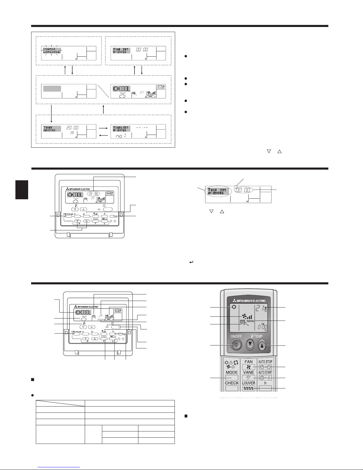
4. Setting the Day of the Week and Time
<Screen Types>
For details on setting the language for the remote controller display, refer
to section 8. Function Selection.
The initial language setting is English.
Function Selection of remote controller:
Set the functions and ranges available to the
remote controller (timer functions, operating
restrictions, etc.)
Set Day/Time: Set the current day of the week or time.
Standard Control Screens:
View and set the air conditioning system’s
operating status
Timer Monitor: View the currently set timer (weekly timer,
simple timer, or Auto Off timer)
Timer Setup: Set the operation of any of the timers (weekly
timer, simple timer, or Auto Off timer).
<How to change the screen>
A : Hold down both the Operation mode button and the Timer On/Off
button for 2 seconds.
B : Press the Timer Menu button.
C : Press the Operation mode (Back) button.
D : Press either of the Set Time buttons ( or ).
3. Screen Configuration
1. Press the or Set Time button 1 to show display 2.
2. Press the Timer On/Off (Set Day) button 9 to set the day.
* Each press advances the day shown at 3 : Sun → Mon → ... → Fri
→ Sat.
3. Press the appropriate Set Time button 1 as necessary to set the time.
* As you hold the button down, the time (at 4) will increment first in
minute intervals, then in ten-minute intervals, and then in one-hour
intervals.
4. After making the appropriate settings at Steps 2 and 3, press the Filter
button 4 to lock in the values.
°F°C
TIMER
MON
OFF
WEEKLY
SUN MON TUE WED THU FRI SAT
WEEKLY
°F°C
°C
TIME SUN
Function Selection of remote controller
Set Day/Time
Standard Control Screens
OFF ON
Timer Monitor Timer Setup
ADC
BC
B
Day of the Week
& Time display
5. Operation
°C
°C
PAR-21MAA
ON/OFF
FILTER
CHECK
OPERATION
CLEAR
TEST
TEMP.
MENU
BACK DAY
MONITOR/SET
CLOCK
ON/OFF
2
7
2
3
3
8
6
4
5
8
7
1
1
5
6
2
5
6
1
2 6
5
3
3
7
7
5.1. Turning ON/OFF
<To Start Operation>
Press the ON/OFF button 1.
• The ON lamp 1 and the display area come on.
Note:
When the unit is restarted, initial settings are as follows.
Remote Controller settings
Mode Last operation mode
Temperature setting Last set temperature
Fan speed Last set fan speed
Airflow up/down Mode
COOL or DRY Last setting
HEAT Last setting
FAN Last setting
<To Stop Operation>
Press the ON/OFF button 1 again.
• The ON lamp 1 and the display area go dark.
Note:
Even if you press the ON/OFF button immediately after shutting down
the operation is progress, the air conditioner will not start for about three
minutes. This is to prevent the internal components from being damaged.
7
GB
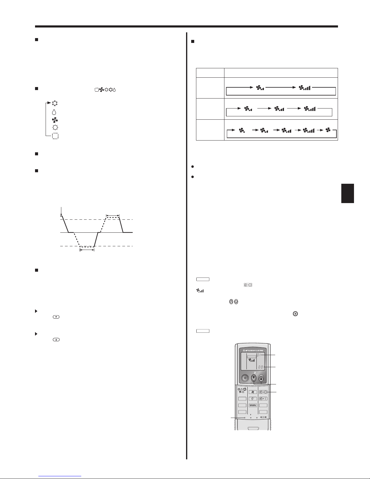
5.4. Fan speed setting
Press the Fan Speed button 5 as many times as necessary while the
system is running.
• Each press changes the force. The currently selected speed is
shown at 5.
• The change sequence, and the available settings, are as follows.
FAN SPEED Display
2 speed
model
Speed 1 Speed 2
3 speed
model
Speed 1 Speed 2 Speed 3
4 speed
+
Auto *
Speed 1 Speed 2 Speed 3 Speed 4
Auto
* For MA remote controller only.
Automatic fan speed setting is necessary for wireless remote controller.
Note:
The number of available fan speeds depends on the type of unit
connected. Note also that some units do not provide an “Auto” setting.
In the following cases, the actual fan speed generated by the unit will differ
from the speed shown the remote controller display.
1. While the display is showing “STAND BY” or “DEFROST”.
2. When the temperature of the heat exchanger is low in the heat mode.
(e.g. immediately after heat operation starts)
3. In HEAT mode, when room temperature is higher than the temperature
setting.
4. When the unit is in DRY mode.
5. Operation
<To Stop Operation>
Press the ON/OFF button 1 again.
• The ON lamp 1 and the display area go dark.
Note:
Even if you press the ON/OFF button immediately after shutting down
the operation is progress, the air conditioner will not start for about three
minutes. This is to prevent the internal components from being damaged.
5.2. Operation mode select
Press the operation mode ( ) button 2 and select the
operation mode 2.
Cool mode
Dry mode
Fan mode
Heat mode
Automatic (cool/heat) operation mode
Automatic operation
According to a set temperature, cooling operation starts if the room
temperature is too hot and heating operation starts if the room
temperature is too cold.
During automatic operation, if the room temperature changes and
remains 1.5 °C or more above the set temperature for 3 minutes, the
air conditioner switches to cool mode. In the same way, if the room
temperature remains 1.5 °C or more below the set temperature for
3 minutes, the air conditioner switches to heat mode.
Because the room temperature is automatically adjusted in order to
maintain a fixed effective temperature, cooling operation is performed
a few degrees warmer and heating operation is performed a few
degrees cooler than the set room temperature once the temperature is
reached (automatic energy-saving operation).
5.3. Temperature setting
To decrease the room temperature:
Press
button 3 to set the desired temperature.
The selected temperature is displayed 3.
To increase the room temperature:
Press button 3 to set the desired temperature.
The selected temperature is displayed 3.
• Available temperature ranges are as follows:
Cooling/Drying: 19 - 30 °C
Heating: 17 - 28 °C
Automatic: 19 - 28 °C
• The display flashes either 8 °C or 39 °C to inform you if the room
temperature is lower or higher than the displayed temperature.
Cool mode
3 minutes (switches
from heating to cooling)
Set temperature +1.5°C
Set temperature
Set temperature -1.5°C
3 minutes (switches
from cooling to heating )
■
Automatic fan speed setting (For wireless remote controller)
It is necessary to set for wireless remote controller only when
automatic fan speed is not set at default setting.
It is not necessary to set for wired remote controller with automatic
fan speed at default setting.
1
Press the SET button with something sharp at the end.
Operate when display of remote controller is off.
MODEL SELECT
blinks and Model No. is lighted
A.
2
Press the AUTO STOP button.
blinks and setting No. is lighted
B.
(Setting No.01: without automatic fan speed )
3
Press the temp.
buttons to set the setting No.02.
(Setting No.02:with automatic fan speed )
If you mistook the operation, press the ON/OFF button and
operate again from procedure 2.
4
Press the SET button with something sharp at the end.
MODEL SELECT
and Model No. are lighted for 3 seconds, then turned off.
ON/OFF TEMP
RESETSET CLOCK
MODEL SELECT
FAN
VANE
TEST RUN
AUTO STOP
AUTO START
h
min
LOUVER
MODE
CHECK
B
A
3
2
14
8
GB
5.5. Airflow up/down direction setting
<To change the airflow up/down direction>
With the unit running, press the Airflow up/down button 6 as
necessary.
• Each press changes the direction. The current direction is shown at
6.
• The change sequence, and the available settings, are as follows.
Airflow Display
4 steps
model
Swing 1 2 3 4
5 steps
model*1
Swing
Auto 1 2
3
4
5
* Note that during swing operation, the directional indication on the
screen does not change in sync with the directional vanes on the
unit.
* Some models do not support directional settings.
*1. For MA remote controller only, other remote controllers display the
same as 4 steps model.
*2. Airflow direction setting <Auto>
COOL/FAN/DRY : Setting 1 (Horizontal),
HEAT : Setting 5 (Downward 5)
Note:
Available directions depend on the type of unit connected. Note also that
some units do not provide an “Auto” setting.
In the following cases, the actual air direction will differ from the direction
indicated on the remote controller display.
1. While the display is showing “STAND BY” or “DEFROST”.
2. Immediately after starting heater mode (while the system is waiting for
the operation mode change to take effect).
3. In heat mode, when room temperature is higher than the temperature
setting.
<[Manual] To Change the Airflow’s Left/Right Direction>
* The louver button 7 cannot be used.
Model PKFY-P·VKM-E
• Stop the unit operation, hold the lever of the louver,
and adjust to the desired direction.
* Do not set to the inside direction when the unit is in
the cooling or drying mode because there is a risk of
condensation and water dripping.
Caution:
To prevent falls, maintain a stable footing when operating the unit.
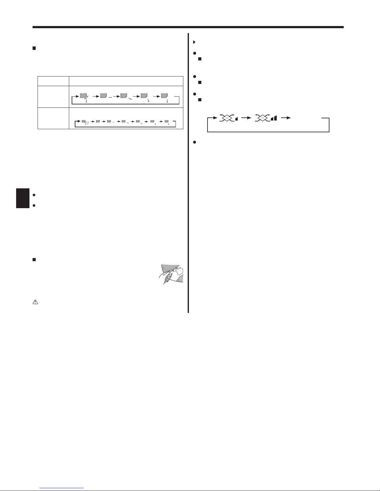
5.6. Ventilation
For LOSSNAY combination
5.6.1. For Wired Remote-controller
To run the ventilator together with the indoor unit:
Press the ON/OFF button 1.
•
The Vent indication appears on the screen (at 8). The ventilator
will now automatically operate whenever the indoor unit is running
.
To run the ventilator only when the indoor unit is off:
Press the Ventilation button 8 while the indoor unit is off.
• The On lamp (at 1) and the Vent indication (at 8) come on.
To change the ventilator force:
Press the Ventilation button 8 as necessary.
• Each press toggles the setting, as shown below.
Note:
With some model configurations, the fan on the indoor unit may come on
even when you set the ventilator to run independently.
5. Operation
(Low) (High)
No display
(Stop)
(OFF)
9
GB
6.1. For Wired Remote-controller
You can use Function Selection of remote controller to select which of
three types of timer to use: 1 Weekly timer, 2 Simple timer, or 3 Auto
Off timer.
6.1.1. Weekly Timer
The weekly timer can be used to set up to eight operations for each
day of the week.
• Each operation may consist of any of the following: ON/OFF time
together with a temperature setting, or ON/OFF time only, or
temperature setting only.
• When the current time reaches a time set at this timer, the air
conditioner carries out the action set by the timer.
Time setting resolution for this timer is 1 minute.
Note:
*1. Weekly Timer/Simple Timer/Auto Off Timer cannot be used at the same
time.
*2. The weekly timer will not operate when any of the following conditions is
in effect.
The timer feature is off; the system is in an malfunction state; a test run
is in progress; the remote controller is undergoing self-check or remote
controller check; the user is in the process of setting a function; the user
is in the process of setting the timer; the user is in the process of setting
the current day of the week or time; the system is under central control.
(Specifically, the system will not carry out operations (unit on, unit off, or
temperature setting) that are prohibited during these conditions.)
°C
SUN
ON
WEEKLY
PAR-21MAA
ON/OFF
FILTER
CHECK
OPERATION
CLEAR
TEST
TEMP.
MENU
BACK DAY
MONITOR/SET
CLOCK
ON/OFF
2
42 3
a9
78
0
4
1
3
b
1
Operation No.
Day Setting
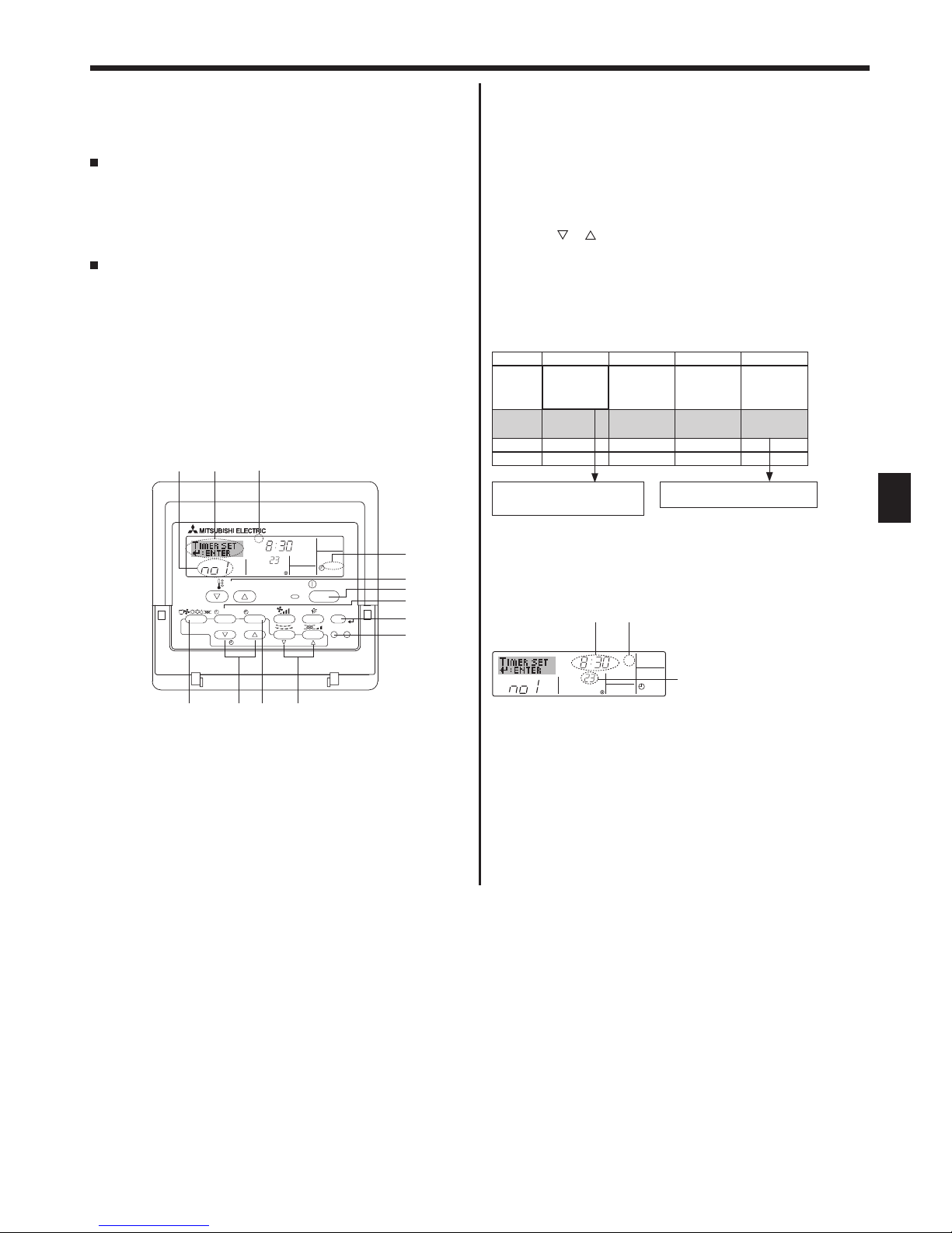
<How to Set the Weekly Timer>
1. Be sure that you are at a standard control screen, and that the weekly
timer indicator 1 is shown in the display.
2. Press the Timer Menu button 2, so that the “Set Up” appears on the
screen (at 2). (Note that each press of the button toggles the display
between “Set Up” and “Monitor”.)
3. Press the Timer On/Off (Set Day) button 9 to set the day. Each
press advances the display at 3 to the next setting, in the following
sequence: “Sun Mon Tues Wed Thurs Fri Sat” → “Sun” →... → “Fri”
→ “Sat” → “Sun Mon Tues Wed Thurs Fri Sat”...
4. Press the
or operation button (7 or 8) as necessary to select
the appropriate operation number (1 to 8) 4.
* Your inputs at Steps 3 and 4 will select one of the cells from the
matrix illustrated below.
(The remote-controller display at left shows how the display would
appear when setting Operation 1 for Sunday to the values indicated
below.)
Setup Matrix
Op No. Sunday Monday ... Saturday
No. 1
• 8:30
• ON
• 23 °C
No. 2
• 10:00
• OFF
• 10:00
• OFF
• 10:00
• OFF
• 10:00
• OFF
...
No. 8
Note:
By setting the day to “Sun Mon Tues Wed Thurs Fri Sat”, you can set the
same operation to be carried out at the same time every day.
(Example: Operation 2 above, which is the same for all days of the week.)
<Setting the Weekly Timer>
5. Press the appropriate Set Time button 1 as necessary to set the
desired time (at 5).
* As you hold the button down, the time first increments in minute
intervals, then in ten-minute intervals, and then in one-hour
intervals.
6. Press the ON/OFF button 1 to select the desired operation (ON or
OFF), at 6.
* Each press changes the next setting, in the following sequence:
No display (no setting) → “ON” → “OFF”
6. Timer
°C
SUN
ON
WEEKLY
6
7
5
Shows the selected operation (ON or OFF)
* Does not appear if operation is not set.
Shows the temperature setting
* Does not appear if temperature is
not set.
Shows the time
setting
<Operation 1 settings for Sunday>
Start the air conditioner at 8:30, with
the temperature set to 23 °C.
<Operation 2 settings for every day>
Turn off the air conditioner at 10:00.
10
GB
7. Press the appropriate Temperature set button 3 to set the desired
temperature (at 7).
* Each press changes the setting, in the following sequence: No
display (no setting)
24 25 ... 29 30 12 ...
23
No display.
(Available range: The range for the setting is 12 °C to 30 °C.
The actual range over which the temperature can be controlled,
however, will vary according to the type of the connected unit.)
8. After making the appropriate settings at Steps 5, 6 and 7, press the
Filter
button 4 to lock in the values.
To clear the currently set values for the selected operation, press
and quickly release the Check (Clear) button 0 once.
* The displayed time setting will change to “—:—”, and the On/Off
and temperature settings will all disappear.
(To clear all weekly timer settings at once, hold down the Check
(Clear) button 0 for 2 seconds or more. The display will begin
flashing, indicating that all settings have been cleared.)
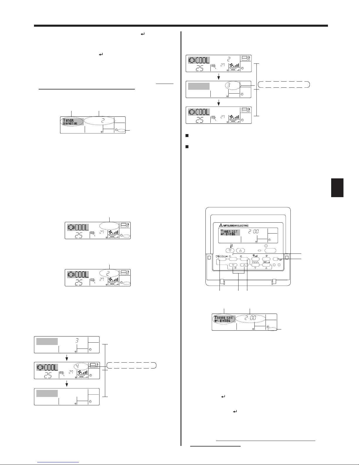
Note:
Your new entries will be cancelled if you press the Operation mode
(Back) button 2 before pressing the Filter
button 4.
If you have set two or more different operations for exactly the same
time, only the operation with the highest Operation No. will be carried
out.
9. Repeat Steps 3 to 8 as necessary to fill as many of the available
cells as you wish.
10. Press the Operation mode (Back) button 2 to return to the
standard control screen and complete the setting procedure.
11. To activate the timer, press the Timer On/Off button 9, so that the
“Timer Off” indication disappears from the screen. Be sure that
the “Timer Off” indication is no longer displayed.
* If there are no timer settings, the “Timer Off” indication will flash
on the screen.
<How to View the Weekly Timer Settings>
1. Be sure that the weekly timer indicator is visible on the screen (at
1).
2. Press the Timer Menu button 2 so that “Monitor” is indicated on
the screen (at 8).
3. Press the Timer On/Off (Set Day) button 9 as necessary to select
the day you wish to view.
4. Press the
or operation button (7 or 8) as necessary to
change the timer operation shown on the display (at 9).
* Each press will advance to the next timer operation, in order of
time setting.
5. To close the monitor and return to the standard control screen,
press the Operation mode (Back) button 2.
<To Turn Off the Weekly Timer>
Press the Timer On/Off button 9 so that “Timer Off” appears at
.
<To Turn On the Weekly Timer>
Press the Timer On/Off button 9 so that the “Timer Off” indication (at )
goes dark.
6.1.2. Simple Timer
You can set the simple timer in any of three ways.
• Start time only:
The air conditioner starts when the set time has elapsed.
• Stop time only:
The air conditioner stops when the set time has elapsed.
• Start & stop times:
The air conditioner starts and stops at the respective elapsed times.
The simple timer (start and stop) can be set only once within a 72-
hour period.
The time setting is made in hour increments.
Note:
*1. Weekly Timer/Simple Timer/Auto Off Timer cannot be used at the same
time.
*2. The simple timer will not operate when any of the following conditions is
in effect.
The timer is off; the system is in malfunction state; a test run is in
progress; the remote controller is undergoing self-check or remote
controller check; the user is in the process of selecting a function; the
user is in the process of setting the timer; the system is under central
control. (Under these conditions, On/Off operation is prohibited.)
<How to Set the Simple Timer>
1. Be sure that you are at a standard control screen, and that the simple
timer indicator is visible in the display (at 1).
When something other than the Simple Timer is displayed, set it to
SIMPLE TIMER using the function selection of remote controller (see
8.[4]–3 (3)) timer function setting.
2. Press the Timer Menu button 2, so that the “Set Up” appears on the
screen (at 2). (Note that each press of the button toggles the display
between “Set Up” and “Monitor”.)
3. Press the ON/OFF button 1 to display the current ON or OFF simple
timer setting. Press the button once to display the time remaining to
ON, and then again to display the time remaining to OFF. (The ON/
OFF indication appears at 3).
• “ON” timer:
The air conditioner will start operation when the specified number of
hours has elapsed.
• “OFF” timer:
The air conditioner will stop operation when the specified number of
hours has elapsed.
4. With “ON” or “OFF” showing at 3: Press the appropriate Set Time
button 1 as necessary to set the hours to ON (if “ON” is displayed) or
the hours to OFF (if “OFF” is displayed) at 4.
• Available Range: 1 to 72 hours
5. To set both the ON and OFF times, repeat Steps 3 and 4.
* Note that ON and OFF times cannot be set to the same value.
6. To clear the current ON or OFF setting: Display the ON or OFF setting
(see step 3) and then press the Check (Clear) button 0 so that the
time setting clears to “—” at 4. (If you want to use only an ON setting
or only an OFF setting, be sure that the setting you do not wish to use
is shown as “—”.)
ONHr
AFTER
SIMPLE
PAR-21MAA
ON/OFF
FILTER
CHECK
OPERATION
CLEAR
TEST
TEMP.
MENU
BACK DAY
MONITOR/SET
CLOCK
ON/OFF
2a9
0
4
1
b
ONHr
AFTER
SIMPLE
4
1
3
2
Timer Setting
Action (On or Off)
* “— —” is displayed if there is no
setting.
°C
°C
TIME SUN
WEEKLY
0
6. Timer
°C
TIMER
SUN
ON
OFF
WEEKLY
1
9
8
°C
°C
TIME SUN
WEEKLY
0
Timer Settings
11
GB
Example 2:
Start the timer, with OFF time is sooner than ON time
ON Setting: 5 hours
OFF Setting: 2 hours
6.1.3. Auto Off Timer
This timer begins countdown when the air conditioner starts, and
shuts the air conditioner off when the set time has elapsed.
Available settings run from 30 minutes to 4 hours, in 30-minute
intervals.
Note:
*1. Weekly Timer/Simple Timer/Auto Off Timer cannot be used at the same
time.
*2. The Auto Off timer will not operate when any of the following conditions
is in effect.
The timer is off; the system is in malfunction state; a test run is in
progress; the remote controller is undergoing self-check or remote
controller check; the user is in the process of selecting a function; the
user is in the process of setting the timer; the system is under central
control. (Under these conditions, On/Off operation is prohibited.)
<How to Set the Auto Off Timer>
1. Be sure that you are at a standard control screen, and that the Auto
Off timer indicator is visible in the display (at 1).
When something other than the Auto Off Timer is displayed, set it to
AUTO OFF TIMER using the function selection of remote controller
(see 8.[4]–3 (3)) timer function setting.
2. Hold down the Timer Menu button 2 for 3 seconds, so that the “Set
Up” appears on the screen (at 2).
(Note that each press of the button toggles the display between “Set
Up” and “Monitor”.)
3. Press the appropriate Set Time button 1 as necessary to set the OFF
time (at 3).
4. Press the Filter
button 4 to lock in the setting.
Note:
Your entry will be cancelled if you press the Operation mode (Back) button 2
before pressing the Filter
button 4.
5. Press the Operation mode (Back) button 2 to complete the setting
procedure and return to the standard control screen.
6. If the air conditioner is already running, the timer starts countdown
immediately. Be sure to check that the timer setting appears
correctly on the display.
7. After completing steps 3 to 6 above, press the Filter button 4 to
lock in the value.
Note:
Your new settings will be cancelled if you press the Operation mode (Back)
button 2 before pressing the Filter button 4.
8. Press the Operation mode (Back) button 2 to return to the standard
control screen.
9. Press the Timer On/Off button 9 to start the timer countdown. When
the timer is running, the timer value is visible on the display. Be sure
that the timer value is visible and appropriate.
<Viewing the Current Simple Timer Settings>
1. Be sure that the simple timer indicator is visible on the screen (at 1).
2. Press the Timer Menu button 2, so that the “Monitor” appears on the
screen (at 5).
• If the ON or OFF simple timer is running, the current timer value will
appear at 6.
• If ON and OFF values have both been set, the two values appear
alternately.
3. Press the Operation mode (Back) button 2 to close the monitor
display and return to the standard control screen.
<To Turn Off the Simple Timer>
Press the Timer On/Off button 9 so that the timer setting no longer
appears on the screen (at 7).
<To Turn On the Simple Timer>
Press the Timer On/Off button 9 so that the timer setting becomes
visible at 7.
Examples
If ON and OFF times have both been set at the simple timer, operation
and display are as indicated below.
Example 1:
Start the timer, with ON time set sooner than OFF time
ON Setting: 3 hours
OFF Setting: 7 hours
TIMER ON
OFFHrAFTER
SIMPLE
1
6
5
Timer Setting
°C
°C
SIMPLE
7
°C
°C
ONHr
AFTER
SIMPLE
7
6. Timer
ONHr
AFTER
SIMPLE
°C
°C
OFFHrAFTER
SIMPLE
SIMPLE
At 3 hours after timer start
Display changes to show the timer’s OFF
setting (hours remaining to OFF).
The time displayed is OFF setting (7 hours)
– ON setting (3 hours) = 4 hours.
At Timer Start
Display shows the timer’s ON setting (hours
remaining to ON).
At 7 hours after timer start
The air conditioner goes off, and will remain
off until someone restarts it.
°C
°C
OFFHrAFTER
SIMPLE
ONHr
AFTER
SIMPLE
°C
°C
SIMPLE
At 2 hours after timer start
Display changes to show the timer’s ON
setting (hours remaining to ON).
The time displayed is ON setting (5 hours)
– OFF setting (2 hours) = 3 hours.
At Timer Start
Display shows the timer’s OFF setting (hours
remaining to OFF).
At 5 hours after timer start
The air conditioner comes on, and will
continue to run until someone turns it off.
AFTER OFF
AUTO OFF
3
1
2
Timer Setting
AFTER OFF
AUTO OFF
PAR-21MAA
ON/OFF
FILTER
CHECK
OPERATION
CLEAR
TEST
TEMP.
MENU
BACK DAY
MONITOR/SET
CLOCK
ON/OFF
2a9
4
b

12
GB
<Checking the Current Auto Off Timer Setting>
1. Be sure that the “Auto Off” is visible on the screen (at 1).
2. Hold down the Timer Menu button 2 for 3 seconds, so that “Monitor”
is indicated on the screen (at 4).
• The timer remaining to shutdown appears at 5.
3. To close the monitor and return to the standard control screen, press
the Operation mode (Back) button 2.
<To Turn Off the Auto Off Timer>
Hold down the Timer On/Off button 9 for 3 seconds, so that “Timer
Off” appears (at 6) and the timer value (at 7) disappears.
Alternatively, turn off the air conditioner itself. The timer value (at 7)
will disappear from the screen.
<To Turn On the Auto Off Timer>
Hold down the Timer On/Off button 9 for 3 seconds. The “Timer
Off” indication disappears (at 6), and the timer setting comes on the
display (at 7).
Alternatively, turn on the air conditioner. The timer value will appear at
7.
AFTER
TIMER
OFF
AUTO OFF
5
1
4
Timer Setting
°C
°C
AUTO OFF
6
7
AUTO OFF
7
°C
°C
AFTER OFF
AUTO OFF
6
7
A
13
2
6.2. For wireless remote controller
1 Press the
AUTO STOP
or
AUTO START
button (TIMER SET).
• Time can be set while the following symbol is blinking.
OFF timer : A is blinking.
ON timer : A is blinking.
2 Use the h and
min
buttons to set the desired time.
3 Canceling the timer.
To cancel the OFF timer, press the
AUTO STOP
button.
To cancel the ON timer, press the
AUTO START
button.
• It is possible to combine both OFF and ON timers.
• Pressing the ON/OFF button of the remote controller during timer
mode to stop the unit will cancel the timers.
• If the current time has not been set, the timer operation cannot be
used.
7. Other Functions
°C
°C
TIME SUN
FUNCTION
PAR-21MAA
ON/OFF
FILTER
CHECK
OPERATION
CLEAR
TEST
TEMP.
MENU
BACK DAY
MONITOR/SET
CLOCK
ON/OFF
4
1
1
Locking function
indicator
7.1. Locking the Remote Controller Buttons
(Operation function limit controller)
If you wish, you can lock the remote controller buttons. You can use
the Function Selection of remote controller to select which type of
locking function to use. (For information about selecting the lock type,
see section 8, item [4]–2 (1)).
Specifically, you can use either of the following two locking functions.
1 Lock All Buttons:
Locks all of the buttons on the remote controller.
2 Lock All Except ON/OFF:
Locks all buttons other than the ON/OFF button.
Note:
The “Locking function” indicator appears on the screen to indicate that
buttons are currently locked.
°C
°C
FUNCTION
1
°C
°C
FUNCTION
1
°C
°C
1
6. Timer
<How to Lock the Buttons>
1. While holding down the Filter button 4, press and hold down the
ON/OFF button 1 for 2 seconds. The “Locking function” indicator
appears on the screen (at 1), indicating that the locking function is
now engaged.
* If locking has been disabled in Function Selection of remote
controller, the screen will display the “Not Available” message when
you press the buttons as described above.
• If you press a locked button, the “Locking function” indicator (at 1)
will blink on the display.
<How to Unlock the Buttons>
1. While holding down the Filter button 4, press and hold down the ON/
OFF button 1 for 2 seconds—so that the “Locking function” indicator
disappears from the screen (at 1).

13
GB
7.2. Error Codes indication
ON/OFF
ERROR CODE
If the ON lamp and error code are both flashing: This means that the air conditioner is out of order and operation has been stopped (and cannot
resume). Take note of the indicated unit number and error code, then switch off the power to the air conditioner and call your dealer or servicer.
Error Code
ON lamp
(Flashing)
ON/OFF
°C
°C
ERROR CODE
ON/OFF
CALL:XXXX
XXX:XXX
Error Code
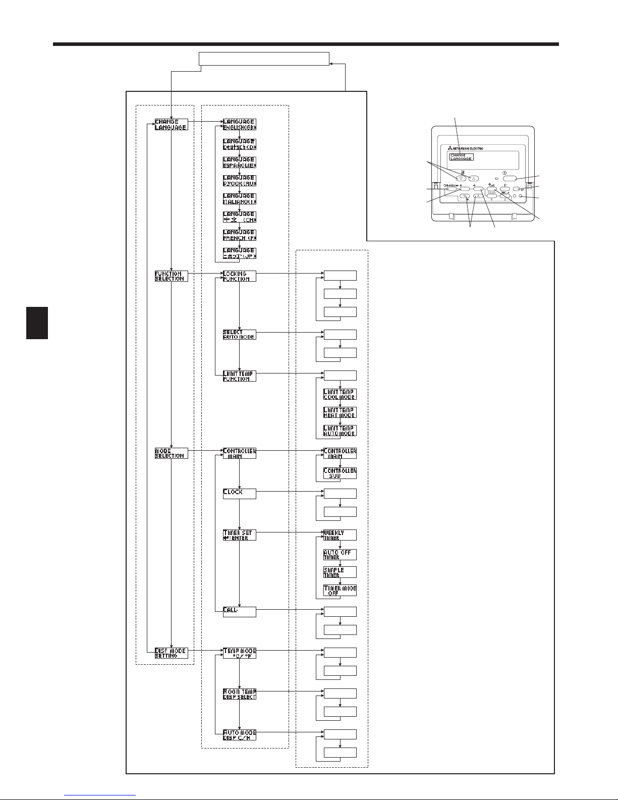
8. Function Selection
Function selection of remote controller
The setting of the following remote controller functions can be changed using the remote controller function selection mode. Change the setting when
needed.
Item 1 Item 2 Item 3 (Setting content)
1. Change Language
(“CHANGE
LANGUAGE”)
Language setting to display • Display in multiple languages is possible
2. Function limit
(“FUNCTION
SELECTION”)
(1) Operation function limit setting (operation lock) (“LOCKING
FUNCTION”)
• Setting the range of operation limit (operation locking function)
(2) Use of automatic mode setting (“SELECT AUTO MODE”) • Setting the use or non-use of “automatic” operation mode
(3) Temperature range limit setting (“LIMIT TEMP FUNCTION”) • Setting the temperature adjustable range (maximum, minimum)
3.Operation mode
selection
(“MODE SELECTION”)
(1) Remote controller main/sub setting (“CONTROLLER MAIN/
SUB”)
• Selecting main or sub remote controller
* When two remote controllers are connected to one group, one
controller must be set to sub.
(2) Use of clock setting (“CLOCK”) • Setting the use or non-use of clock function
(3) Timer function setting (“WEEKLY TIMER”) • Setting the timer type
(4) Contact number setting for error situation (“CALL.”) • Contact number display in case of error
• Setting the telephone number
4. Display change
(“DISP MODE
SETTING”)
(1) Temperature display °C/°F setting (“TEMP MODE °C/°F”) • Setting the temperature unit (°C or °F) to display
(2) Suction air temperature display setting (“ROOM TEMP DISP
SELECT”).
• Setting the use or non-use of the display of indoor (suction) air
temperature
(3) Automatic cooling/heating display setting (“AUTO MODE DISP
C/H”)
• Setting the use or non-use of the display of “Cooling” or “Heating”
display during operation with automatic mode
7. Other Functions
When the Check button is pressed:
If you have entered contact number to be called in the event of a problem, the screen displays this number.
(You can set this up under Function Selection of remote controller. For information, refer to section 8.)
If only the error code is flashing (while the ON lamp remains lit): Operation is continuing, but there may be a problem with the system. In this case,
you should note down the error code and then call your dealer or servicer for advice.
* If you have entered contact number to be called in the event of a problem, push the Check button to display it on the screen. (You can set this up
under Function Selection of remote controller. For information, refer to section 8.)
Indoor Unit No.
14
GB
OFF
on1
on2
OFF
ON
OFF
ON
OFF
OFF
CALL-
ON
OFF
ON
OFF
C
F
PAR-21MAA
ON/OFF
FILTER
CHECK
OPERATION
CLEAR
TEST
TEMP.
MENU
BACK DAY
MONITOR/SET
CLOCK
ON/OFF
F
E
G
C
D
H
B
A
I
G
G
G
G
G
G
E
E
G
G
G
G
G
E
G
E
G
G
G
G
D
D
D
D
D
D
D
D
D
D
D
D
D
D
D
D
D
D
D
D
D
D
D
D
D
D
D
D
D
D
English
Germany
Spanish
Russian
Italy
Chinese
French
Japanese
[Function selection flowchart]
Setting language (English)
Hold down the E button and press the D button for 2 seconds.
Hold down the E button and press the D button for 2 seconds.
Remote controller function selection mode
E Press the operation mode button.
G Press the TIMER MENU button.
D Press the TIMER ON/OFF button.
Item1 Item2
Dot display
Item3
Room air temperature is not displayed.
One of “Automatic cooling” and “Automatic heating” is displayed
under the automatic mode is running. (Initial setting value)
Only “Automatic” is displayed under the automatic mode.
Change
Language
Function
selection
Operation
mode
selection
Display
mode setting
8. Function Selection
Operation locking function setting is not used.
(Initial setting value)
Operation lock setting is except On/Off button.
Operation lock setting is All buttons.
The automatic mode is displayed when the operation mode is
selected. (Initial setting value)
The automatic mode is not displayed when the operation mode
is selected.
The temperature range limit is not active. (Initial setting value)
The temperature range can be changed on cool/dry operation
mode.
The temperature range can be changed on heat operation mode.
The temperature range can be changed on automatic mode.
The remote controller will be the main controller. (Initial setting value)
The remote controller will be the sub controller.
The clock function can be used. (Initial setting value)
The clock function can not be used.
Weekly timer can be used. (Initial setting value)
Auto off timer can be used.
Simple timer can be used.
Timer mode can not be used.
The set contact numbers are not displayed in case of error.
(Initial setting value)
The set contact numbers are displayed in case of error.
The temperature unit °C is used. (Initial setting value)
The temperature unit °F is used.
Room air temperature is displayed. (Initial setting value)
Normal display
(Display when the air condition is not running)
German
Italian
15
GB
[Detailed setting]
[4]–1. CHANGE LANGUAGE setting
The language that appears on the dot display can be selected.
• Press the [ MENU] button G to change the language.
1
English (GB), 2 German (D), 3 Spanish (E), 4 Russian (RU),
5 Italian (I), 6 Chinese (CH), 7 French (F), 8 Japanese (JP)
Refer to the dot display table.
[4]–2. Function limit
(1) Operation function limit setting (operation locking function)
• To switch the setting, press the [ ON/OFF] button D.
1 no1 : Operation lock setting is made on all buttons other than
the [
ON/OFF] button.
2 no2 : Operation lock setting is made on all buttons.
3 OFF (Initial setting value): Operation lock setting is not made.
* To make the operation lock setting valid on the normal screen,
it is necessary to press buttons (Press and hold down the
[FILTER] and [ ON/OFF] buttons at the same time for 2
seconds.) on the normal screen after the above setting is made.
(2) Use of automatic mode setting
When the remote controller is connected to the unit that has
automatic operation mode, the following settings can be made.
• To switch the setting, press the [ ON/OFF] button D.
1 ON (Initial setting value):
The automatic mode is displayed when the operation mode is
selected.
2 OFF:
The automatic mode is not displayed when the operation
mode is selected.
(3) Temperature range limit setting
After this setting is made, the temperature can be changed within
the set range.
• To switch the setting, press the [ ON/OFF] button D.
1 LIMIT TEMP COOL MODE:
The temperature range can be changed on cool/dry mode.
2 LIMIT TEMP HEAT MODE:
The temperature range can be changed on heat mode.
3 LIMIT TEMP AUTO MODE:
The temperature range can be changed on automatic mode.
4 OFF (initial setting): The temperature range limit is not active.
* When the setting, other than OFF, is made, the temperature
range limit setting on cool, heat and automatic mode is made at
the same time. However, the range cannot be limited when the
set temperature range has not changed.
• To increase or decrease the temperature, press the [ TEMP.
( ) or ( )] button F.
• To switch the upper limit setting and the lower limit setting,
press the [ ] button H. The selected setting will flash and the
temperature can be set.
• Settable range
Cool/Dry mode:
Lower limit:19°C - 30°C Upper limit:30°C - 19°C
Heat mode:
Lower limit:17°C - 28°C Upper limit:28°C - 17°C
Automatic mode:
Lower limit:19°C - 28°C Upper limit:28°C - 19°C
8. Function Selection
[4]–3. Operation mode selection setting
(1) Remote controller main/sub setting
• To switch the setting, press the [ ON/OFF] button D.
1 Main: The controller will be the main controller.
2 Sub: The controller will be the sub controller.
(2) Use of clock setting
• To switch the setting, press the [
ON/OFF] button D.
1 ON: The clock function can be used.
2 OFF: The clock function cannot be used.
(3) Timer function setting
• To switch the setting, press the [ ON/OFF] button D (Choose
one of the followings.).
1 WEEKLY TIMER (initial setting value):
The weekly timer can be used.
2 AUTO OFF TIMER:
The auto off timer can be used.
3 SIMPLE TIMER:
The simple timer can be used.
4 TIMER MODE OFF:
The timer mode cannot be used.
* When the use of clock setting is OFF, the “WEEKLY TIMER”
cannot be used.
(4) Contact number setting for error situation
• To switch the setting, press the [ ON/OFF] button D.
1 CALL OFF:
The set contact numbers are not displayed in case of error.
2 CALL **** *** ****:
The set contact numbers are displayed in case of error.
CALL_:
The contact number can be set when the display is as shown
on the left.
• Setting the contact numbers
To set the contact numbers, follow the following procedures.
Move the flashing cursor to set numbers. Press the [ TEMP.
(
) and ( )] button F to move the cursor to the right (left).
Press the [ CLOCK ( ) and ( )] button C to set the
numbers.
[4]–4. Display change setting
(1) Temperature display °C/°F setting
• To switch the setting, press the [ ON/OFF] button D.
1 °C: The temperature unit °C is used.
2 °F: The temperature unit °F is used.
(2) Suction air temperature display setting
• To switch the setting, press the [
ON/OFF] button D.
1 ON: The suction air temperature is displayed.
2 OFF: The suction air temperature is not displayed.
(3) Automatic cooling/heating display setting
• To switch the setting, press the [ ON/OFF] button D.
1 ON:
One of “Automatic cooling” and “Automatic heating” is
displayed under the automatic mode is running.
2 OFF:
Only “Automatic” is displayed under the automatic mode.
16
GB
8. Function Selection
[Dot display table]
Selecting language English German Spanish Russian Italian Chinese French Japanese
Waiting for start-up
Operation mode Cool
Dry
Heat
Auto
Auto(Cool)
Auto(Heat)
Fan
Ventilation
Stand by
(Hot adjust)
Defrost
Set temperature
Fan speed
Not use button
Check (Error)
Test run
Self check
Unit function selection
Setting of ventilation
Selecting language English German Spanish Russian Italian Chinese French Japanese
CHANGE LANGUAGE
Function selection
Operation function limit setting
Use of automatic mode setting
Temperature range limit setting
Limit temperature cool/day mode
Limit temperature heat mode
Limit temperature auto mode
Operation mode selection
Remote controller setting MAIN
Remote controller setting SUB
Use of clock setting
Setting the day of the week and
time
Timer set
Timer monitor
Weekly timer
Timer mode off
Auto off timer
Simple timer
Contact number setting of error
situation
Display change
Temperature display °C/°F
setting
Air inlet temperature display
setting
Automatic cool/heat display
setting
17
GB
9. Emergency Operation for Wireless Remote-controller
PKFY-P·VKM-E
B
A
E
C
D
When the remote controller cannot be used
When the batteries of the remote controller run out or the remote
controller malfunctions, the emergency operation can be done using the
emergency buttons on the grille.
A DEFROST/STAND BY lamp
B Operation lamp
C Emergency operation cooling switch
D Emergency operation heating switch
E Receiver
Starting operation
• To operate the cooling mode, press the button C for more than 2
seconds.
• To operate the heating mode, press the button D for more than 2
seconds.
• Lighting of the Operation lamp B means the start of operation.
Note:
Details of emergency mode are as shown below.
Details of EMERGENCY MODE are as shown below.
Operation mode COOL HEAT
Set temperature 24°C 24°C
Fan speed High High
Airflow direction Horizontal Downward 4 (5)
Stopping operation
• To stop operation, press the button C or the button D for more
than 2 seconds.
BAECD
PLFY-P·VCM-E2
PCFY-P·VKM-E
ON/OFF
TEMP.
°C
°C
FILTER
Indicates that the filter needs cleaning.
Clean the filter.
When resetting “FILTER” display
When the [FILTER] button is pressed two times successively after
cleaning the filter, the display goes off and is reset.
Note:
When two or more different types of indoor unit are controlled, the
cleaning period differs with the type of filter. When the master unit
cleaning period arrives, “FILTER” is displayed. When the filter display
goes off, the cumulative time is reset.
“FILTER” indicates the cleaning period when the air conditioner was used
under general indoor air conditions by criteria time. Since the degree
of dirtiness depends on the environmental conditions, clean the filter
accordingly.
The filter cleaning period cumulative time differs with the model.
This indication is not available for wireless remote controller.
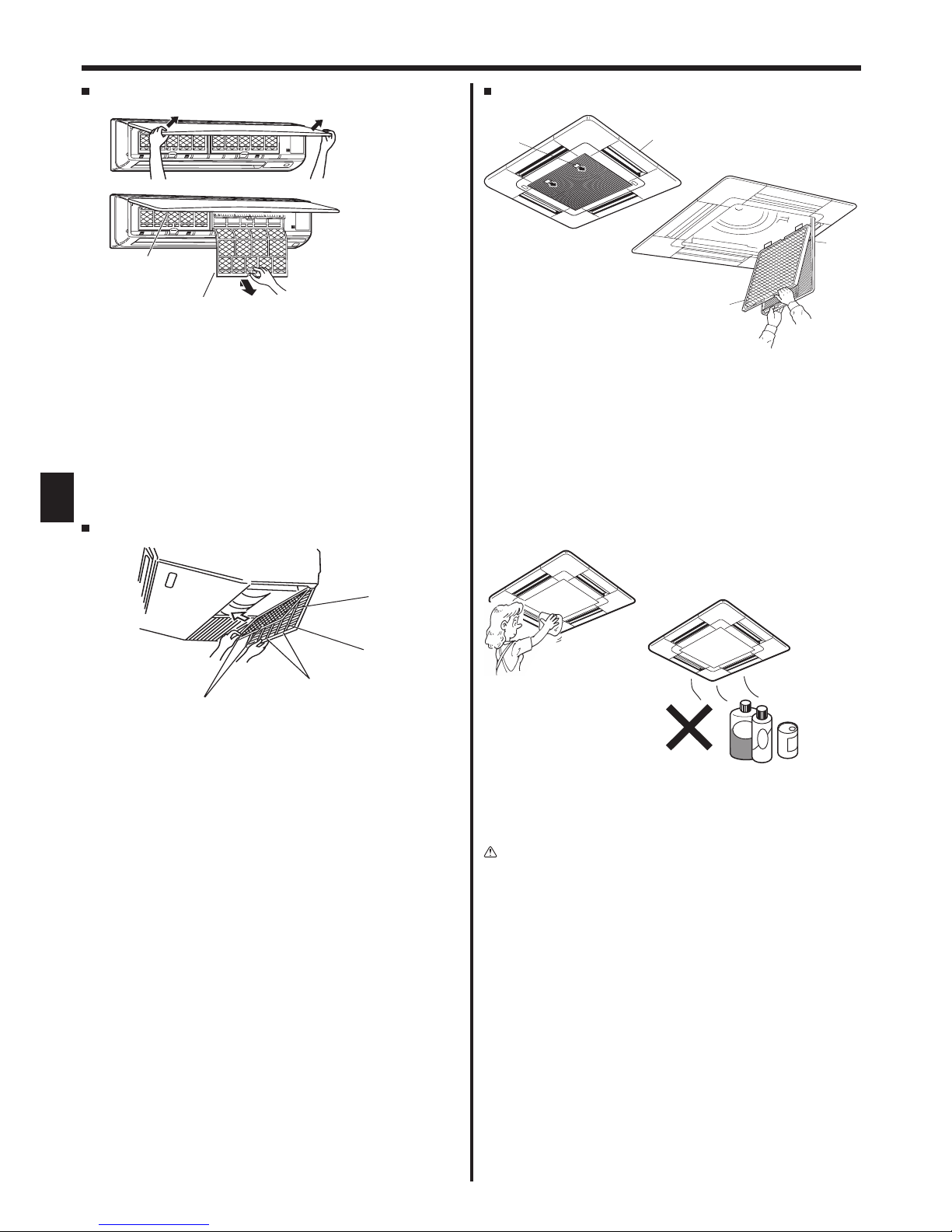
Cleaning the filters
• Clean the filters using a vacuum cleaner. If you do not have a vacuum
cleaner, tap the filters against a solid object to knock off dirt and dust.
• If the filters are especially dirty, wash them in lukewarm water. Take
care to rinse off any detergent thoroughly and allow the filters to dry
completely before putting them back into the unit.
Caution:
• Do not dry the filters in direct sunlight or by using a heat source,
such as an electric heater: this may warp them.
• Do not wash the filters in hot water (above 50°C), as this may
warp them.
• Make sure that the air filters are always installed. Operating the
unit without air filters can cause malfunction.
Caution:
• Before you start cleaning, stop operation and turn OFF the power
supply.
• Indoor units are equipped with filters to remove the dust of suckedin air. Clean the filters using the methods shown in the following
sketches.
Caution:
• In removing the filter, precautions must be taken to protect your
eyes from dust. Also, if you have to climb up on a stool to do the
job, be careful not to fall.
• When the filter is removed, do not touch the metallic parts inside
the indoor unit, otherwise injury may result.
10. Care and Cleaning
18
GB
10. Care and Cleaning
PLFY-P·VCM-E2
1 Pull the knob on the intake grille in the direction indicated by the
arrow and it should open.
2 Open the intake grille.
3 Release the knob on the center edge of the intake grille and pull
the filter forward to remove the filter.
A Knob
B Grille
C Intake grille
D Filter
B
A
D
C
Cleaning the indoor unit
• Wipe the outside of the unit with a clean, dry, soft cloth.
• Clean off any oil stains or finger marks using a neutral household
detergent (such as dishwashing liquid or laundry detergent).
Caution:
Never use gasoline, benzene, thinner, scouring powder or any type
of non-neutral detergent, as these substances may damage the
unit’s case.
PKFY-P·VKM-E
1 Using both hands, pull both the bottom corners of the inlet grille to
open the grille, then lift the filter until it clicks at the stop position.
2 Hold the knobs on the filter and pull the filter up, then pull it out
downward.
(Located in two places, on the left and right.)
A Front grille
B Filter
B
A
1 Open the intake grille.
2 Hold the knob on the filter then pull the filter up in the direction of
an arrow. To replace the filter after cleaning, be sure to insert the
filter far enough until it fits into the stopper.
A Filter B Intake Grille C Knob D Stopper
PCFY-P·VKM-E
A
B
C
D
19
GB
11. Troubleshooting
Having trouble? Here is the solution. (Unit is operating normally.)
Air conditioner does not heat or cool well.
Clean the filter. (Airflow is reduced when the filter is dirty or clogged.)
Check the temperature adjustment and adjust the set temperature.
Make sure that there is plenty of space around the outdoor unit. Is the
indoor unit air inlet or outlet blocked?
Has a door or window been left open?
When heating operation starts, warm air does not blow from the indoor
unit soon.
Warm air does not blow until the indoor unit has sufficiently warmed
up.
During heat mode, the air conditioner stops before the set room
temperature is reached.
When the outdoor temperature is low and the humidity is high,
frost may form on the outdoor unit. If this occurs, the outdoor unit
performs a defrosting operation. Normal operation should begin after
approximately 10 minutes.
Airflow up/down direction changes during operation or airflow up/down
direction cannot be set.
During cool mode, the vanes automatically move to the horizontal
(down) position after 1 hour when the down (horizontal) airflow up/
down direction is selected. This is to prevent water from forming and
dripping from the vanes.
During heat mode, the vanes automatically move to the horizontal
airflow up/down direction when the airflow temperature is low or
during defrosting mode.
When the airflow up/down direction is changed, the vanes always move
up and down past the set position before finally stopping at the position.
When the airflow up/down direction is changed, the vanes move to the
set position after detecting the base position.
A flowing water sound or occasional hissing sound is heard.
These sounds can be heard when refrigerant is flowing in the air
conditioner or when the refrigerant flow is changing.
A cracking or creaking sound is heard.
These sounds can be heard when parts rub against each due to
expansion and contraction from temperature changes.
The room has an unpleasant odor.
The indoor unit draws in air that contains gases produced from the
walls, carpeting, and furniture as well as odors trapped in clothing,
and then blows this air back into the room.
A white mist or vapor is emitted from the indoor unit.
If the indoor temperature and the humidity are high, this condition may
occur when operation starts.
During defrosting mode, cool airflow may blow down and appear like a
mist.
Water or vapor is emitted from the outdoor unit.
During cool mode, water may form and drip from the cool pipes and
joints.
During heat mode, water may form and drip from the heat exchanger.
During defrosting mode, water on the heat exchanger evaporates and
water vapor may be emitted.
The operation indicator does not appear in the remote controller display.
Turn on the power switch. “ ” will appear in the remote controller
display.
The air conditioner does not operate even though the ON/OFF button
is pressed. The operation mode display on the remote controller
disappears.
Is the power switch of the indoor unit turned off? Turn on the power
switch.
“ ” appears in the remote controller display. During central control, “ ” appears in the remote controller display
and air conditioner operation cannot be started or stopped using the
remote controller.
When restarting the air conditioner soon after stopping it, it does not
operate even though the ON/OFF button is pressed.
Wait approximately three minutes.
(Operation has stopped to protect the air conditioner.)
Air conditioner operates without the ON/OFF button being pressed.
Is the on timer set?
Press the ON/OFF button to stop operation.
Is the air conditioner connected to a central remote controller?
Consult the concerned people who control the air conditioner.
Does “ ” appear in the remote controller display?
Consult the concerned people who control the air conditioner.
Has the auto recovery feature from power failures been set?
Press the ON/OFF button to stop operation.
Air conditioner stops without the ON/OFF button being pressed.
Is the off timer set?
Press the ON/OFF button to restart operation.
Is the air conditioner connected to a central remote controller?
Consult the concerned people who control the air conditioner.
Does “ ” appear in the remote controller display?
Consult the concerned people who control the air conditioner.
Remote controller timer operation cannot be set.
Are timer settings invalid?
If the timer can be set,
WEEKLY, SIMPLE
, or
AUTO OFF
appears in
the remote controller display.
“PLEASE WAIT” appears in the remote controller display.
The initial settings are being performed. Wait approximately 3
minutes.
An error code appears in the remote controller display.
The protection devices have operated to protect the air conditioner.
Do not attempt to repair this equipment by yourself.
Turn off the power switch immediately and consult your dealer. Be
sure to provide the dealer with the model name and information that
appeared in the remote controller display.
Draining water or motor rotation sound is heard.
When cooling operation stops, the drain pump operates and then
stops. Wait approximately 3 minutes.
20
GB
Having trouble? Here is the solution. (Unit is operating normally.)
Noise is louder than specifications.
The indoor operation sound level is affected by the acoustics of the
particular room as shown in the following table and will be higher than
the noise specification, which was measured in an echo-free room.
High soundabsorbing rooms
Normal rooms Low sound-
absorbing rooms
Location
examples
Broadcasting
studio, music
room, etc.
Reception room,
hotel lobby, etc.
Office, hotel
room
Noise levels 3 to 7 dB 6 to 10 dB 9 to 13 dB
Nothing appears in the wireless remote controller display, the display
is faint, or signals are not received by the indoor unit unless the remote
controller is close.
The batteries are low.
Replace the batteries and press the Reset button.
If nothing appears even after the batteries are replaced, make sure
that the batteries are installed in the correct directions (+, –).
The operation lamp near the receiver for the wireless remote controller
on the indoor unit is flashing.
The self diagnosis function has operated to protect the air conditioner.
Do not attempt to repair this equipment by yourself.
Turn off the power switch immediately and consult your dealer. Be
sure to provide the dealer with the model name.
Warm air blows from the indoor unit intermittently when heat mode is off
or during fan mode.
When another indoor unit is operating in heat mode, the control
valve opens and closes occasionally to maintain stability in the air
conditioning system. This operation will stop after a while.
* If this will cause an undesirable rise in the room temperature in
small rooms, etc., stop the operation of the indoor unit temporarily.
Range of application
The range of working temperatures for both the indoor and outdoor units of the series Y, R2, Multi-S is as below.
Warning:
If the air conditioner operates but does not cool or heat (depending on model) the room, consult your dealer since there may be a
refrigerant leak. Be sure to ask the service representative whether there is refrigerant leakage or not when repairs are carried out.
The refrigerant charged in the air conditioner is safe. Refrigerant normally does not leak, however, if refrigerant gas leaks indoors, and
comes into contact with the fire of a fan heater, space heater, stove, etc., harmful substances will be generated.
11. Troubleshooting
21
GB
Model PKFY-P63VKM-E PKFY-P100VKM-E
Power source (Voltage<V>/Frequency) <Hz> ~N/220-230-240/50, 220/60
Capacity (Cooling/Heating) <kW> 7.1/8.0 11.2/12.5
Dimension (Height) <mm> 365
Dimension (Width) <mm> 1170
Dimension (Depth) <mm> 295
Net weight <kg> 22
Fan Airflow volume (Low-High) <m
3
/min> 16-20 20-25
Noise level (Low-High) <dB> 39-43 41-49
Model
PLFY-P15VCM-E2 PLFY-P20VCM-E2 PLFY-P25VCM-E2 PLFY-P32VCM-E2 PLFY-P40VCM-E2
Power source (Voltage<V>/Frequency) <Hz> ~N/220-230-240/50
Capacity (Cooling/Heating) <kW> 1.7/1.9 2.2/2.5 2.8/3.2 3.6/4.0 4.5/5.0
Dimension (Height) <mm> 208 (20)
Dimension (Width) <mm> 570 (650)
Dimension (Depth) <mm> 570 (650)
Net weight <kg> 15.5 (3) 17.0 (3)
Fan Airflow volume (Low-Middle-High) <m
3
/min> 8-8.5-9 8-9-10 8-9-11
Noise level (Low-Middle-High) <dB> 28-30-31 28-31-35 28-31-37 29-33-38 30-34-39
Model PCFY-P40VKM-E PCFY-P63VKM-E PCFY-P100VKM-E PCFY-P125VKM-E
Power source (Voltage<V>/Frequency) <Hz> ~/N 220-230-240/50, 220/60
Capacity (Cooling/Heating) <kW> 4.5/5.0 7.1/8.0 11.2/12.5 14.0/16.0
Dimension (Height) <mm> 230
Dimension (Width) <mm> 960 1280 1600
Dimension (Depth) <mm> 680
Net weight <kg> 24 32 36 38
Fan Airflow volume (Low-Middle2-Middle1-High)
<m3/min> 10-11-12-13 14-15-16-18 21-24-26-28 21-24-27-31
Noise level (Low-Middle2-Middle1-High) <dB> 29-32-34-36 31-33-35-37 36-38-41-43 36-39-42-44
Note
* Operation temperature of indoor unit.
Cooling mode: 15°C WB - 24°C WB
Heating mode: 15°C DB - 27°C DB
*1 Cooling/Heating capacity indicates the maximum value at operation under the following condition.
Cooling: Indoor 27 °C DB/19 °C WB, Outdoor 35 °C DB
Heating: Indoor 20 °C DB, Outdoor 7 °C DB/6 °C WB
*2 This figure ( ) indicates panel’s.
12. Specifications
22
D
Inhaltsverzeichnis
1. Sicherheitsvorkehrungen
Vor dem Einbau der Anlage vergewissern, dass Sie alle
Informationen über “Sicherheitsvorkehrungen” gelesen haben.
Die “Sicherheitsvorkehrungen” enthalten sehr wichtige
Sicherheitsgesichtspunkte. Sie sollten sie unbedingt befolgen.
Vor Anschluss an das System Mitteilung an
Stromversorgungsunternehmen machen oder dessen
Genehmigung einholen.
Raum mit hoher Luftfeuchtigkeit (80% oder mehr) betrieben wird,
kann in der Klimaanlage kondensiertes Wasser abtropfen und
Möbel usw. nass werden lassen oder beschädigen.
•
Berühren Sie während des Betriebs nicht den Flügel des oberen
Luftauslasses oder den Dämpfer des unteren Luftauslasses.
Dadurch kann Kondensation auftreten, wodurch der Betrieb stoppt.
Die Anlage entsorgen
Zum Entsorgen des Gerätes wenden Sie sich an Ihren Kundendienst.
Vorsicht:
•
Zum Drücken der Tasten keine scharfen Gegenstände benutzen,
da dadurch die Fernbedienung beschädigt werden kann.
• Die Ansaug- oder Austrittsöffnungen weder der Innennoch der Außenanlage blockieren oder abdecken.
• Die Fernbedienung niemals mit Benzol, Verdünner, mit
Chemikalien getränkten Putzlappen usw. abwischen.
•
Betreiben Sie die Klimaanlage niemals für längere Zeit bei hoher
Luftfeuchtigkeit, z. B. bei geöffneter Tür oder geöffnetem Fenster.
Falls die Klimaanlage für längere Zeit im Kühlbetrieb in einem
• Diese Klimaanlage darf NICHT von Kindern oder
unsicheren Personen ohne Aufsicht benutzt werden.
•
Kleine Kinder müssen beaufsichtigt werden, um sicherzustellen,
dass sie nicht an der Klimaanlage herumspielen.
• Wenn gasförmiges oder flüssiges Kühlmittel entweicht,
die Klimaanlage abstellen, den Raum ausreichend lüften
und das Verkaufsgeschäft benachrichtigen.
•
Dieses Gerät ist nicht zur Verwendung durch Personen
(einschließlich Kindern) mit reduzierten körperlichen, sensorischen
oder mentalen Fähigkeiten oder mangelnden Erfahrungen oder
Kenntnissen vorgesehen, es sei denn, sie werden durch eine für
ihre Sicherheit verantwortliche Person beaufsichtigt oder wurden
von dieser in der Verwendung des Geräts unterwiesen.
•
Beim Installieren oder Umsetzen oder Warten der
Klimaanlage darf nur das angegebene Kältemittel (R410A)
zur Befüllung der Kältemittelleitungen verwendet werden.
Vermischen Sie es nicht mit anderem Kältemittel und lassen
Sie nicht zu, dass Luft in den Leitungen zurückbleibt.
Wenn sich Luft mit dem Kältemittel vermischt, kann dies zu
einem ungewöhnlich hohen Druck in der Kältemittelleitung führen
und eine Explosion oder andere Gefahren verursachen. Die
Verwendung eines anderen als des für das System angegebenen
Kältemittels führt zu mechanischem Versagen, einer Fehlfunktion
des Systems oder einer Beschädigung des Geräts. Im
schlimmsten Fall kann sie ein schwerwiegendes Hindernis für die
Aufrechterhaltung der Produktsicherheit darstellen.
Warnung:
• Diese Geräte sind nicht allgemein zugänglich.
• Die Anlage sollte nicht vom Benutzer eingebaut werden.
Bitten Sie Ihren Händler oder eine Vertragswerkstatt,
die Anlage einzubauen. Wenn die Anlage unsachgemäß
eingebaut wurde, kann Wasser auslaufen, können
Stromschläge erfolgen, oder es kann Feuer ausbrechen.
•
Nicht auf die Anlage stellen oder Gegenstände darauf ablegen.
•
Kein Wasser über die Anlage spritzen und die Anlage auch nicht
mit nassen Händen berühren. Dies kann zu Stromschlägen führen.
• Kein brennbares Gas in der Nähe der Anlage versprühen.
Es kann Feuer ausbrechen.
•
Keine Gasheizung oder sonstige Geräte mit offenen Flammen
in Bereichen abstellen, an denen Luft aus der Anlage
ausströmt. Unvollständige Verbrennung kann die Folge sein.
• Wenn die Anlage läuft, nicht die Frontplatte oder den
Gebläseschutz von der Außenanlage abnehmen.
• Sie sollten die Anlage niemals eigenhändig reparieren
oder an einen anderen Standort verbringen.
•
Wenn das Geräusch oder die Vibrationen anders als normal oder
besonders stark sind, den Betrieb einstellen, den Hauptschalter
ausschalten, und das Verkaufsgeschäft um Hilfe bitten.
• Niemals die Finger, Stöcke etc. in de Ansaug- oder
Austrittsöffnungen stecken.
•
Wenn Sie merkwürdige Gerüche feststellen, sollten Sie die Anlage
nicht mehr benutzen, den Strom abschalten und sich an Ihren
Kundendienst wenden, da sonst schwere Defekte an der Anlage,
ein Stromschlag oder ein Brand verursacht werden können.
Im Text verwendete Symbole
Warnung:
Beschreibt Vorkehrungen, die beachtet werden sollten, um den Benutzer
vor der Gefahr von Verletzungen oder tödlicher Unfälle zu bewahren.
Vorsicht:
Beschreibt Vorkehrungen, die beachtet werden sollten,
damit an der Anlage keine Schäden entstehen.
In den Abbildungen verwendete Symbole
: Verweist auf einen Teil der Anlage, der geerdet werden muss.
1. Sicherheitsvorkehrungen .....................................................22
2. Bezeichnungen der Teile .....................................................23
3. Bildschirmkonfiguration .......................................................26
4. Einstellen des Wochentags und der Zeit .............................26
5. Bedienung ...........................................................................26
6. Timer ...................................................................................29
7. Weitere Funktionen .............................................................32
8. Funktionsauswahl ................................................................33
9. Notbetrieb bei schnurloser Fernbedienung .........................37
10. Pflege und Reinigung ..........................................................37
11. Fehlerbehebung ..................................................................39
12. Technische Daten ................................................................41
Hinweis:
Der Begriff “Verdrahte Fernbedienung” in dieser Bedienungsanleitung bezieht sich auf den PAR-21MAA.
Entnehmen Sie weitere Informationen zur anderen Fernbedienung dem in diesem Paketen beiliegenden Bedienungshandbuch.
Dieses Kennzeichnungssymbol gilt nur für EU-Länder.
Dieses Kennzeichnungssymbol entspricht der Richtlinie 2002/96/EG Artikel 10 Information für die Nutzer und Anhang IV,
und/oder der Richtlinie 2006/66/EG Artikel 20 Information für die Endnutzer und Anhang II.
Ihr MITSUBISHI ELECTRIC-Produkt wurde unter Einsatz von qualitativ hochwertigen Materialien und Komponenten konstruiert und
gefertigt, die für Recycling und/oder Wiederverwendung geeignet sind.Dieses Symbol bedeutet, dass elektrische und elektronische
Geräte sowie Batterien und Akkus am Ende ihrer Nutzungsdauer von Hausmüll getrennt zu entsorgen sind. Wenn ein chemisches Symbol
unterhalb des Symbols (Fig.1), bedeutet dies, dass die Batterie bzw. der Akku ein Schwermetall in einer bestimmten Konzentration enthält.
Dies wird wie folgt angegeben: Hg: Quecksilber (0,0005 %), Cd: Cadmium (0,002 %), Pb: Blei (0,004 %)
In der Europäischen Union gibt es unterschiedliche Sammelsysteme für gebrauchte Elektrik- und Elektronikgeräte einerseits sowie
Batterien und Akkus andererseits. Bitte entsorgen Sie dieses Gerät, Batterien und Akkus vorschriftsmäßig bei Ihrer kommunalen
Sammelstelle oder im örtlichen Recycling-Zentrum. Bitte helfen Sie uns, die Umwelt zu erhalten, in der wir leben!
Hinweis
Fig.1
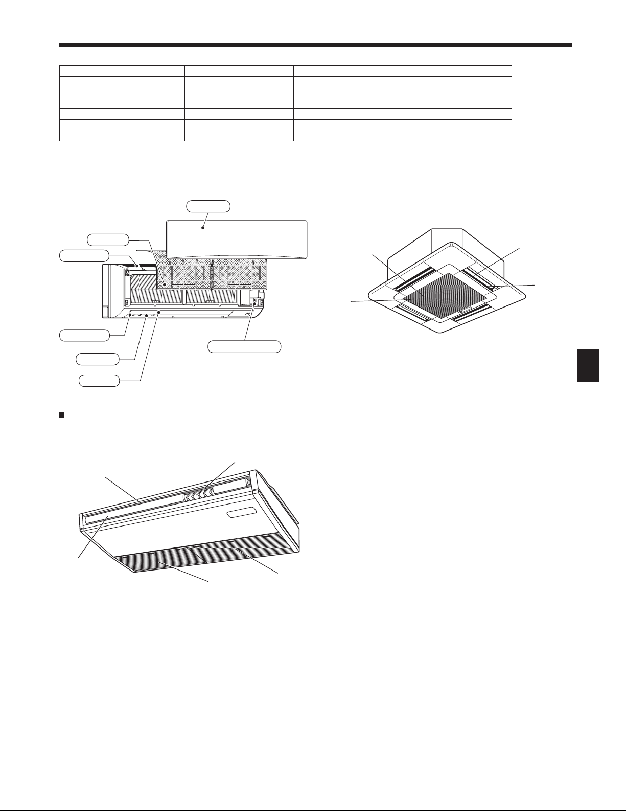
23
D
2. Bezeichnungen der Teile
Klappe
PKFY-P·VKM-E
Wandinstallation
Filter
Lufteinlass
Luftauslass
Luftklappe
Frontgitter
Notbetriebsschalter
PLFY-P·VCM-E2
4- Wege-Deckenkassette
Filter
Lufteinlass
Klappe
Luftauslass
Inneneinheit
PKFY-P·VKM-E PLFY-P·VCM-E2
PCFY-P·VKM-E
Lüfterstufen 2 Geschwindigkeitsstufen 3 Geschwindigkeitsstufen
4 Geschwindigkeit+Autom.*
Klappe
Stufen 4 Stufen 4 Stufen
5 Stufen
Auto-Schwingen
{{
{
Luftklappe Manuell ―
Manuell
Filter Normal Langlebig
Langlebig
Reinigungsempfehlung für Filter 100 Std. 2.500 Std.
2.500 Std.
Filter
(Inneres der Luftansaugung)
PCFY-P·VKM-E
Unterdeckengerät
Klappe
Lufteinlass
Luftauslass
Luftklappe
* Diese Bedienung ist nur durch Verwendung der Fernbedienung
möglich, die die Gebläsegeschwindigkeit auf "Autom." stellen kann.
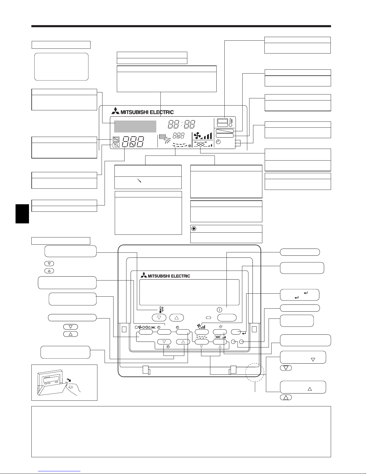
24
D
Für verdrahtete Fernbedienung (optionaler Bauteil)
°F°C
°F°C
ERROR CODE
AFTER
TIMER
TIME SUN MON TUE WED THU FRI SAT
ON
OFF
Hr
AFTER
FILTER
FUNCTION
ONLY1Hr.
WEEKLY
SIMPLE
AUTO OFF
PAR-21MAA
ON/OFF
FILTER
CHECK
OPERATION
CLEAR
TEST
TEMP.
MENU
BACK DAY
MONITOR/SET
CLOCK
ON/OFF
Nach unten
Nach oben
Zurück
Vorwärts
Öffnen der
Tür.
Zur vorherigen
Betriebsnummer.
Zur nächsten
Betriebsnummer.
2. Bezeichnungen der Teile
Eingebauter Temperatursensor
Display-Bereich
Zeigt den aktuellen Betrieb
Zeigt den Betriebsmodus, usw.
* Anzeige in mehreren Sprachen
wird unterstützt.
Anzeige “Centrally Controlled”
Gibt an, dass der Betrieb der
Fernbedienung durch eine MasterSteuerung deaktiviert wurde.
Anzeige “Timer is Off”
Gibt an, dass der Timer
ausgeschaltet ist.
Anzeige “One Hour Only”
Wird angezeigt, wenn der Luftstrom
in der Betriebsart COOL oder DRY
auf schwach und abwärts eingestellt
ist. (Der Betrieb unterscheidet sich je
nach Modell.)
Die Anzeige schaltet sich nach einer
Stunde aus, wenn sich die Richtung
des Luftstroms ebenfalls ändert.
Temperatureinstellung
Zeigt die Zieltemperatur an.
Anzeige der Luftrichtung nach
oben/nach unten
Die Anzeige gibt die Richtung der
herausströmenden Luft an.
Wochentag
Zeigt den aktuellen Wochentag an.
Anzeige der Umgebungstemperatur
Zeigt die Umgebungstemperatur
an. Der Anzeigebereich für die
Umgebungstemperatur ist 8 – 39 °C.
Die Anzeige blinkt, wenn die Temperatur
weniger als 8 °C oder mehr als 39 °C
beträgt.
Zeit-/Timer-Anzeige
Zeigt die aktuelle Zeit an, außer der einfache oder der
Auto-Off-Timer ist eingestellt.
Falls der einfache oder der Auto-Off-Timer eingestellt
ist, wird die Restzeit angezeigt.
Anzeige der Luftklappen
Gibt die Aktion der Schwingluftklappen
an. Erscheint nicht, wenn die Luftklappe
stationär ist.
(Netz-Ein-Anzeige)
Gibt an, dass der Netzschalter
eingeschaltet ist.
Anzeige der
Lüftergeschwindigkeit
Zeigt die ausgewählte
Lüftergeschwindigkeit an.
Belüftungsanzeige
Erscheint, wenn das Gerät im
Belüftungsmodus läuft.
Sensoranzeige
Wird angezeigt, wenn die
Fernbedienung verwendet wird.
Sperrfunktionsanzeige
Gibt an, dass die Tasten der
Fernbedienung gesperrt wurden.
Filterreinigungsanzeige
Erscheint, wenn der Filter gereinigt
werden muss.
Timer-Anzeigen
Die Anzeige erscheint, wenn der
entsprechende Timer eingestellt ist.
Hinweis:
Meldung “PLEASE WAIT” (BITTE WARTEN)
Diese Meldung wird etwa 3 Minuten lang angezeigt, wenn das Innengerät mit Strom versorgt wird.
Blinkende Betriebsartanzeige
Bei Anschluss mehrerer Innenanlagen an eine einzelne Außenanlage und wenn für eine Innenanlage eine Betriebsart gewählt wurde, die sich von der laufenden Betriebsart einer anderen
Innenanlage unterscheidet, blinkt die Betriebsartanzeige. Wählen Sie bitte für die andere Innenanlage die gleiche Betriebsart.
Meldung “NOT AVAILABLE” (NICHT VERFÜGBAR)
Diese Meldung wird angezeigt, wenn eine Taste für eine Funktion gedrückt wird, über die das Innengerät nicht verfügt.
Wenn zur Bedienung mehrerer Innengeräte verschiedener Modelle gleichzeitig eine einzige Fernbedienung benutzt wird, wird diese Meldung nicht angezeigt, wenn eines der Geräte über die Funktion verfügt.
Anzeige der Raumtemperatur
Die Temperaturfühler der Innenanlage oder der Temperaturfühler der Fernbedienung können zum Messen der Raumtemperatur gewählt werden. Die Temperaturfühler der Innenanlage bilden die
anfängliche Einstellung. Wenn die Temperaturfühler der Innenanlage zum Messen der Raumtemperatur gewählt werden, wird auf der Fernbedienung, die die Mehrfachinnenanlagen steuert, die
an der Hauptinnenanlage gemessene Raumtemperatur angezeigt.
Tasten zum Einstellen
der Temperatur
Taste Timer-Menü
(Taste Monitor/Einstellen)
Taste Betriebsart
(Taste Zurück)
Taste Zeit einstellen
Taste Timer Aus/Ein
(Taste Tag einstellen)
Taste ON/OFF
Taste
Lüftergeschwindigkeit
Taste Filter
(Taste
)
Taste Testlauf
Taste Check
(Taste Löschen)
Taste Luftstrom nach
oben/nach unten
Taste Luftklappe
(Taste Betrieb
)
Taste Belüftung
(Taste Betrieb
)
Für diese Erklärung werden
alle Teile des Displays als
beleuchtet dargestellt. Während
dem tatsächlichen Betrieb sind
nur die relevanten Elemente
beleuchtet.
Kontrollbereich
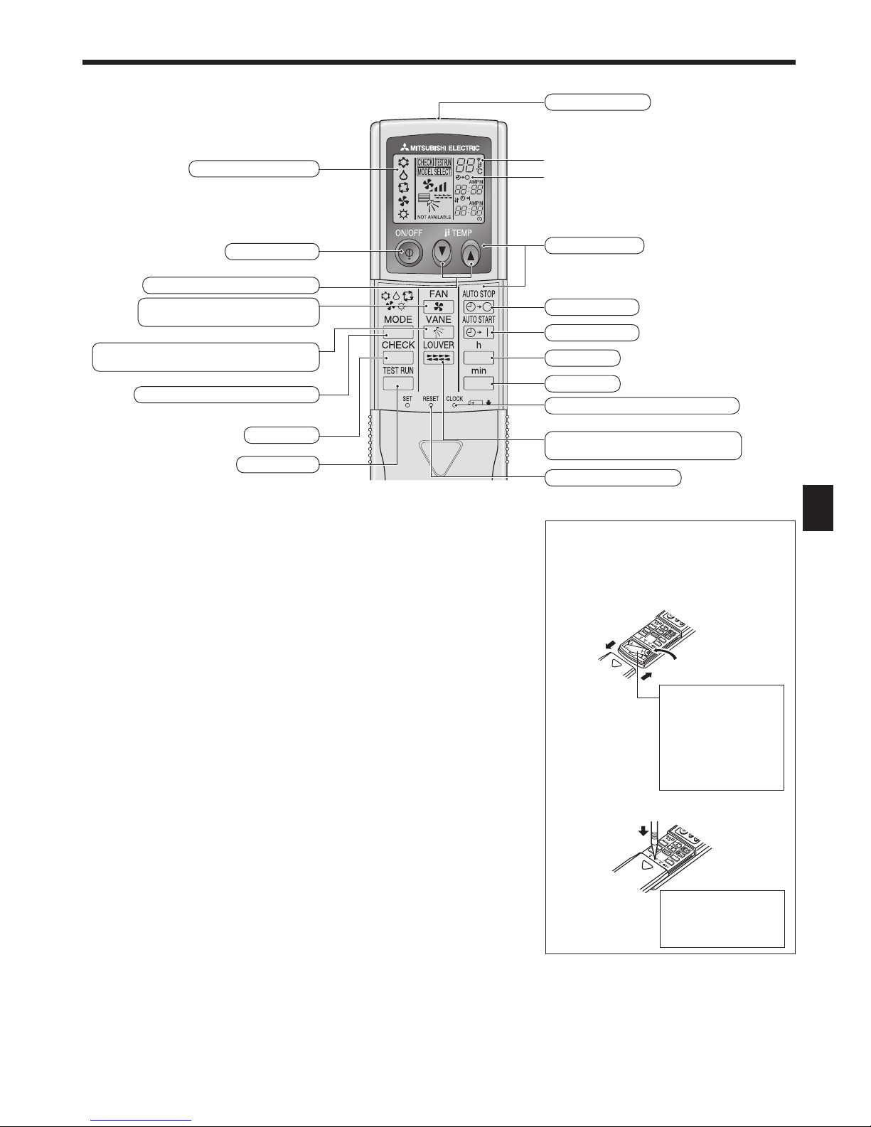
25
D
Für die schnurlose Fernbedienung (optionaler Bauteil)
2. Bezeichnungen der Teile
Übertragungsanzeige
Timer-Anzeige
Zur Benutzung der schnurlosen Fernbedienung diese auf den Empfänger am Innengerät
richten.
Wird die Fernbedienung innerhalb von etwa 2 Minuten betätigt, nachdem das Innengerät
eingeschaltet wurde, erklingt unter Umständen zweimal ein Piepton während das Gerät
die automatische Anfangsprüfung durchführt.
Das Innengerät piept zur Bestätigung, dass das Signal, das von der Fernbedienung
übertragen wird, empfangen wurde. Signale können bis zu etwa 7 Meter Sichtlinie vom
Innengerät in einem Winkel von 45° nach links und rechts vom Gerät empfangen werden.
Jedoch kann der Empfang des Innengeräts durch Beleuchtung wie Leuchtstofflampen
oder starkes Licht beeinträchtigt werden.
Wenn die Betriebsanzeige in der Nähe des Empfängers am Innengerät blinkt, muss das
Gerät geprüft werden. Wenden Sie sich an Ihren Händler für Service.
Behandeln Sie die Fernbedienung pfleglich! Lassen Sie sie nicht fallen und schützen Sie
sie vor starken Erschütterungen. Schützen Sie die Fernbedienung darüber hinaus vor
Wasser und hoher Luftfeuchtigkeit.
Um ein Verlegen der Fernbedienung zu vermeiden, montieren Sie den Halter, der mit der
Fernbedienung geliefert wurde, an einer Wand und legen Sie die Fernbedienung nach
Gebrauch stets in den Halter zurück.
* Zur Erläuterung sind alle Anzeigen, die auf
dem Display erscheinen können, abgebildet.
* Es werden alle Anzeigen angezeigt, wenn
die Reset-Taste gedrückt wird.
Display der Fernbedienung
Taste ON/OFF
Tasten zum Einstellen der Temperatur
Taste Lüftergeschwindigkeit (Ändert
Lüftergeschwindigkeit)
Taste Luftstrom (Ändert Richtung des Luftstroms
nach oben/unten)
Taste Modus (Ändert Betriebsmodus)
Taste Check
Taste Testlauf
Übertragungsfläche
Bedienungsflächen
Taste Timer aus
Taste Timer ein
Taste Stunde
Taste Minute
Taste Zeit einstellen (Stellt die Uhrzeit ein)
Taste Luftklappe (Ändert die Richtung des
Luftstroms nach links/rechts)
Taste Reset (Zurücksetzen)
Einsetzen/Austausch der Batterien
1. Nehmen Sie die obere Abdeckung ab und
legen Sie zwei AAA-Batterien ein. Schließen
Sie dann die obere Abdeckung wieder.
2. Drücken Sie die Taste Reset (Zurücksetzen).
1
2
3
Obere
Abdeckung
Zwei AAA-Batterien
Legen Sie den
negativen (–) Pol
der Batterien zuerst
ein. Setzen Sie
die Batterien in die
richtige Richtung (+, –)
zeigend ein!
Drücken Sie die Taste
Reset (Zurücksetzen)
mit einem spitzen
Gegenstand.
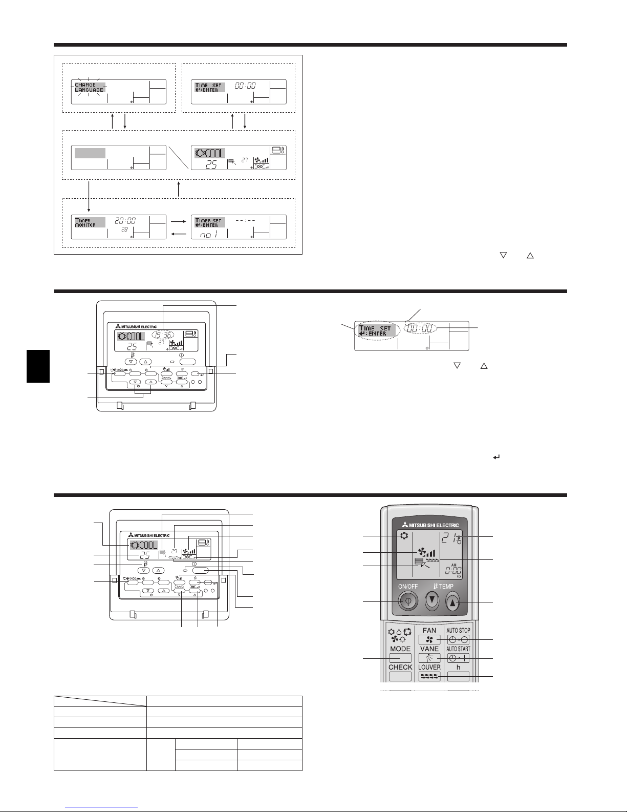
26
D
Hinweis:
Der Tag und die Zeit erscheinen nicht, wenn die Uhr in der Funktionsauswahl
deaktiviert wurde.
°C
°C
TIME SUN
PAR-21MAA
ON/OFF
FILTER
CHECK
OPERATION
CLEAR
TEST
TEMP.
MENU
BACK DAY
MONITOR/SET
CLOCK
ON/OFF
2
4
9
1
a
Zeit-Einstellung
TIME SUN
2
3
4
Einstellung des Wochentags
4. Einstellen des Wochentags und der Zeit
°C
°C
PAR-21MAA
ON/OFF
FILTER
CHECK
OPERATION
CLEAR
TEST
TEMP.
MENU
BACK DAY
MONITOR/SET
CLOCK
ON/OFF
2
7
2
3
3
8
6
4
5
8
7
1
1
5
6
2
5
6
1
2 6
5
3
3
7
7
5.1. ON/OFF (Ein-/Ausschalten)
<So starten Sie den Betrieb>
Drücken Sie die Taste ON/OFF 1.
• Die Lampe EIN 1 und der Anzeigebereich erscheinen.
Hinweis:
Wenn das Gerät neu gestartet wird, sind die Anfangseinstellungen wie folgt.
Fernbedienungseinstellungen
Modus Letzte Betriebsart
Temperatureinstellung Letzte Temperatureinstellung
Lüftergeschwindigkeit Letzte Lüftergeschwindigkeitseinstellung
Luftstrom nach oben/nach unten
Modus
COOL oder DRY Letzte Einstellung
HEAT Letzte Einstellung
FAN Letzte Einstellung
<Bildschirmtypen>
Mit der Funktionsauswahl der Fernbedienung kann die Spracheinstellung
des Displays auf German (Deutsch) umgestellt werden. In Abschnitt 8,
Punkt [4]–1 sehen Sie, wie Sie die Spracheinstellung ändern.
Die anfängliche Einstellung ist Englisch.
Funktionsauswahl: Stellt die verfügbaren Funktionen und Bereiche
auf der Fernbedienung ein (Timer-Funktionen,
Betriebsbeschränkungen, usw.).
Tag/Zeit einstellen: Stellt den aktuellen Wochentag oder die Zeit ein.
Standard-Kontrollbildschirme:
Zeigt den Betriebsstatus des
Klimaanlagensystems und stellt ihn ein.
Timer-Monitor: Zeigt den aktuell eingestellten Timer an
(wöchentlicher Timer, einfacher Timer oder AutoOff-Timer).
Timer-Setup: Stellt den Betriebs eines der Timer ein
(wöchentlicher Timer, einfacher Timer oder AutoOff-Timer).
<So wechseln Sie den Bildschirm>
Zu
A : Halten Sie sowohl die Taste Betriebsart als auch die Taste
Timer Ein/Aus 2 Sekunden lang gedrückt.
Zu B : Drücken Sie die Taste Timer-Menü.
Zu C : Drücken Sie die Taste Betriebsart (Zurück).
Zu D : Drücken Sie eine der Tasten Zeit einstellen ( oder ).
°F°C
TIMER
MON
OFF
WEEKLY
SUN MON TUE WED THU FRI SAT
WEEKLY
°F°C
°C
TIME SUN
Funktionsauswahl Tag/Zeit einstellen
Standardkontrollbildschirme
OFF ON
Timer-Monitor Timer-Setup
ADC
BC
B
3. Bildschirmkonfiguration
5. Bedienung
1. Drücken Sie die Taste Zeit einstellen oder 1 um 2 anzuzeigen.
2. Drücken Sie die Taste Timer Ein/Aus (Tag einstellen) 9, um den Tag
einzustellen.
* Mit jedem Drücken rückt die Anzeige unter 3 einen Tag vor: Sun →
Mon → ... → Fri → Sat.
3. Drücken Sie die entsprechenden Taste Zeit einstellen 1 nach Bedarf,
um die Zeit einzustellen.
* Wenn Sie die Taste gedrückt halten, rückt die Zeit (unter 4) zuerst in
Minutenintervallen vor, dann in Zehn-Minuten-Intervallen und dann in
Ein-Stunden-Intervallen.
4. Nachdem Sie die entsprechenden Einstellungen unter Schritt 2 und 3
durchgeführt haben, drücken Sie die Taste Filter 4 um die Werte zu
speichern.
<So stoppen Sie den Betrieb>
Drücken Sie die Taste ON/OFF 1 nochmals.
• Die Lampe ON 1 und die Anzeige erlöschen.
Hinweis:
Selbst wenn Sie die Taste ON/OFF unmittelbar nach dem Ausschalten des
laufenden Geräts drücken, kann die Klimaanlage etwa drei Minuten lang nicht
gestartet werden. Dadurch wird verhindert, dass Teile im Inneren der Anlage
beschädigt werden.
Anzeige des
Wochentags und
der Zeit
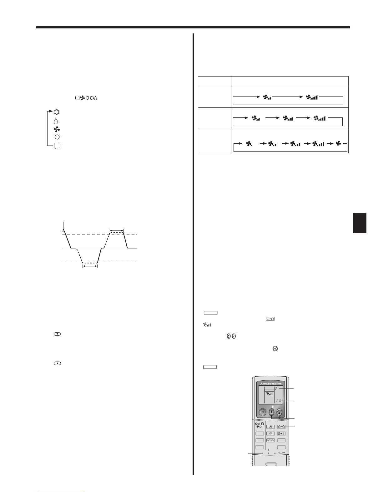
27
D
5. Bedienung
<So stoppen Sie den Betrieb>
Drücken Sie die Taste ON/OFF 1 erneut.
• Die Lampe EIN 1 und der Display-Bereich verschwinden.
Hinweis:
Selbst wenn Sie die ON/OFF (NETZSTROM EIN/AUS-) Taste unmittelbar
nach Abschaltung des in Gang befindlichen Betriebs drücken, beginnt die
Klimaanlage etwa drei Minuten lang nicht zu laufen. Dadurch wird verhindert,
dass Teile im Inneren der Anlage beschädigt werden.
5.2. Betriebsart wählen
Die Betriebsart ( )-Taste 2 drücken und die Betriebsart
wählen 2.
Kühlen
Trocknen
Gebläse
Heizen
Automatik (Kühlen/Heizen)
Automatischer Betrieb
Eine Temperatur wird eingestellt und der Kühlbetrieb beginnt, wenn
die Umgebungstemperatur zu hoch ist bzw. der Heizbetrieb beginnt,
wenn sie zu niedrig ist.
Im automatischen Betrieb schaltet die Klimaanlage in die Betriebsart
Kühlen, wenn die Umgebungstemperatur sich ändert und 3 Minuten
lang 1,5 °C oder mehr über der eingestellten Temperatur liegt.
Ebenso schaltet die Klimaanlage in die Betriebsart Heizen, wenn die
Umgebungstemperatur 3 Minuten lang 1,5 °C oder mehr unter der
eingestellten Temperatur liegt.
Da die Umgebungstemperatur automatisch angepasst wird, um eine
festgelegte tatsächliche Temperatur beizubehalten, wird das Kühlen
einige Grade wärmer und das Heizen einige Grade kühler ausgeführt
als die eingestellte Umgebungstemperatur, sobald die Temperatur
erreicht ist (automatisches Energiesparen).
5.3. Temperatureinstellung
Zum Absenken der Raumtemperatur:
Taste drücken 3, um die gewünschte Raumtemperatur
einzustellen.
Die eingestellte Raumtemperatur wird angezeigt 3.
Zur Erhöhung der Raumtemperatur:
Taste drücken 3, um die gewünschte Raumtemperatur
einzustellen.
Die eingestellte Temperatur wird angezeigt 3.
• Folgende Temperaturbereiche sind verfügbar:
Kühlen und Trocknen: 19 - 30 °C
Heizen: 17 - 28 °C
Automatik: 19 - 28 °C
• Die Anzeige blinkt bei 8 °C oder 39 °C und informiert so darüber
ob die Raumtemperatur höher oder niedriger als die angezeigte
Temperatur ist.
Kühlen
3 Minuten (schaltet von
Heizen auf Kühlen)
Eingestellte
Temperatur +1,5°C
Eingestellte Temperatur
Eingestellte
Temperatur -1,5°C
3 Minuten (schaltet von
Kühlen auf Heizen)
5.4. Einstellung der Lüftergeschwindigkeit
Drücken Sie die Taste Lüftergeschwindigkeit 5 so oft wie nötig,
während das System läuft.
• Jedes Drücken ändert die Stärke. Die aktuell ausgewählte
Geschwindigkeit ist unter 5 dargestellt
• Die Änderungsreihenfolge und die verfügbaren Einstellungen sind
wie folgt.
LÜFTERGESCHWINDIGKEIT
Anzeige
2-Geschwindigkeitsstufen-
Modell
Geschwindigkeit 1 Geschwindigkeit 2
3-Geschwindigkeitsstufen-
Modell
Geschwindigkeit 1 Geschwindigkeit 2 Geschwindigkeit 3
4 Geschwindigkeiten
+
Autom.*
* Nur für MA-Fernbedienung.
Automatische Gebläsegeschwindigkeit-Einstellung ist für drahtlose
Fernbedienung erforderlich.
Hinweis:
Die Anzahl der verfügbaren Lüftergeschwindigkeiten hängt von der Art des
angeschlossenen Geräts ab. Beachten Sie außerdem, dass einige Geräte
die Einstellung “Auto” nicht haben.
In den folgenden Fällen unterscheidet sich die vom Gerät
erzeugte tatsächliche Lüftergeschwindigkeit von der auf der
Fernbedienungsanzeige angezeigten Geschwindigkeit:
1. Während das Display “STAND BY” oder “DEFROST” anzeigt.
2. Wenn die Temperatur des Wärmetauschers in der Betriebsart Heizen zu
niedrig ist. (z.B. direkt nach dem Heizbeginn)
3. Im HEAT-Modus, wenn die Raumtemperatur höher als die
Temperatureinstellung ist.
4. Wenn sich das Gerät im DRY-Modus befindet.
Automatische Einstellung der Lüfterdrehzahl (für drahtlose
Fernbedienung)
Die Einstellung ist bei drahtloser Fernbedienung nur notwendig, wenn
die automatische Lüfterdrehzahl bei der Standardeinstellung nicht
eingestellt wird.
Die Einstellung ist nicht notwendig bei verdrahteter Fernbedienung mit
automatischer Lüfterdrehzahl bei Standardeinstellung.
1
SET-Taste mit einem spitzen Gegenstand drücken.
Dies muss bei ausgeschaltetem Display der Fernbedienung erfolgen.
MODEL SELECT
blinkt und die Modellnummer wird hervorgehoben A.
2
AUTO STOP-Taste betätigen. .
blinkt und die Einstell-Nummer wird hervorgehoben B.
(Einstell-Nr. 01: ohne automatische Lüfterdrehzahl)
3
Die Tasten drücken, um die Einstell-Nr. 02 einzustellen.
(Einstellung 02: mit automatischer Lüfterdrehzahl)
Bei einem Fehler ist die ON/OFF -Taste zu drücken und der
Vorgang ab Schritt 2 zu wiederholen.
4
SET-Taste mit einem spitzen Gegenstand drücken.
MODEL SELECT
und die Modellnummer leuchten 3 Sekunden lang auf und
verschwinden dann.
Geschwindigkeit 1
Autom.
Geschwindigkeit 2 Geschwindigkeit 3 Geschwindigkeit 4
ON/OFF TEMP
RESETSET CLOCK
MODEL SELECT
FAN
VANE
TEST RUN
AUTO STOP
AUTO START
h
min
LOUVER
MODE
CHECK
B
A
3
2
14
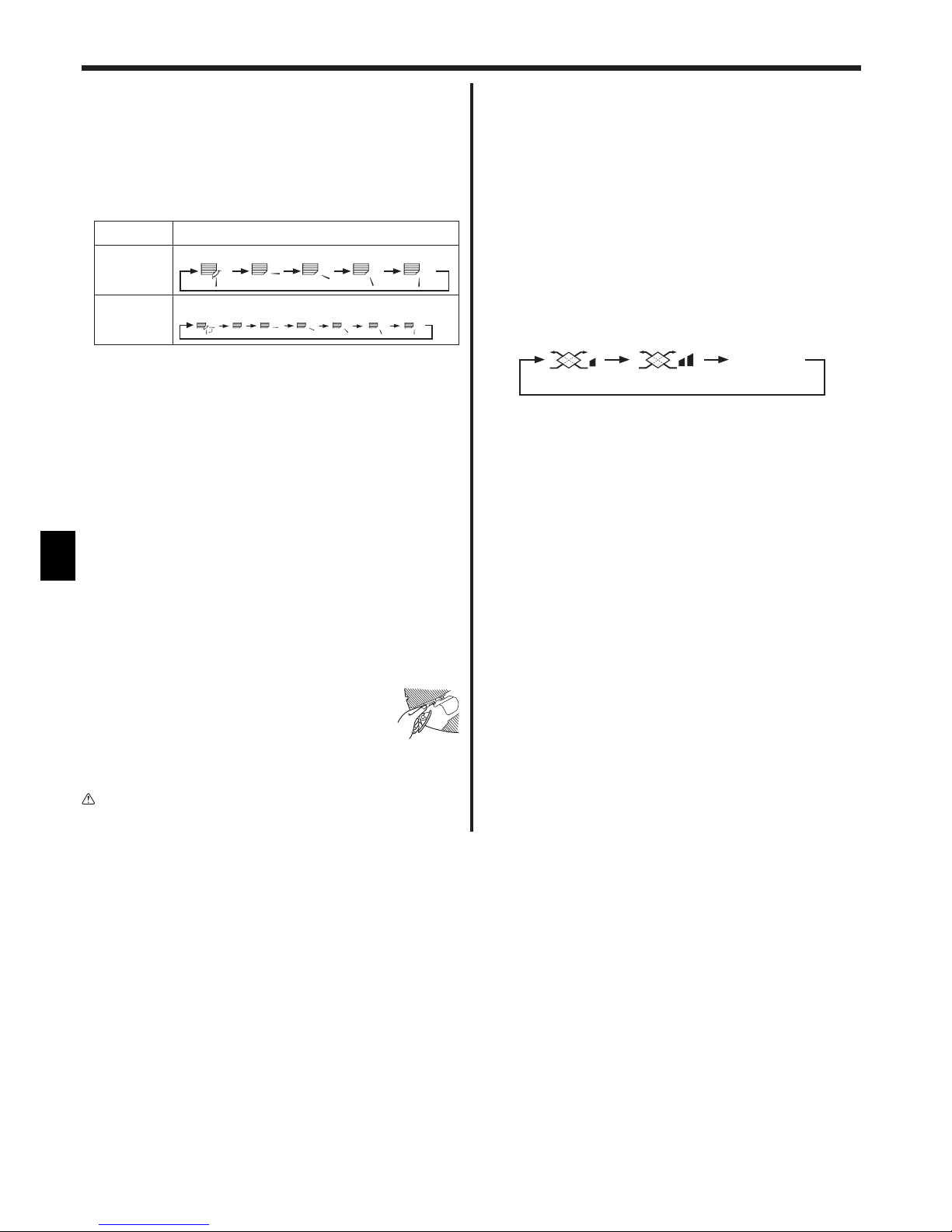
28
D
5.5. Einstellung der Luftstromrichtung
<So ändern Sie die Richtung des Luftstroms (nach oben/nach
unten)>
Drücken Sie, während das Gerät läuft, die Taste Luftstrom nach oben/
nach unten 6 nach Bedarf.
• Jedes Drücken ändert die Richtung. Die aktuelle Richtung wird
unter 6 angezeigt.
• Die Änderungsreihenfolge und die verfügbaren Einstellungen sind
wie folgt:
Luftstrom Anzeige
4-Stufen-
Modell
Schwingen 1 2 3 4
5-Stufen-
Modell *1
* Beachten Sie, dass sich während dem Schwingbetrieb die
Richtungsanzeige auf dem Bildschirm nicht synchron mit den
Richtungsklappen am Gerät ändert.
* Einige Modelle unterstützen Richtungseinstellungen nicht.
*1 Nur für MA-Fernbedienung, andere Fernbedienungen zeigen das
gleiche an wie das 4-Schritt-Modell.
*2
Einstellung der Luftstromrichtung <Autom.>
COOL/FAN/DRY : Einstellung 1 (Horizontal), HEAT : Einstellung 5 (Abwärts 5)
Hinweis:
Die verfügbaren Richtungen hängen von der Art des angeschlossenen
Geräts ab. Beachten Sie außerdem, dass einige Geräte die Einstellung
“Auto” nicht haben.
In den folgenden Fällen unterscheidet sich die tatsächliche Luftrichtung
von der Richtung, die auf der Fernbedienungsanzeige angezeigt wird:
1. Während das Display “STAND BY” oder “DEFROST” anzeigt.
2. Sofort nach Starten des Heizmodus (während das System darauf wartet,
dass sich die Betriebsart ändert).
3. Im Heizmodus, wenn die Raumtemperatur höher als die
Temperatureinstellung ist.
<[Manuell] Ändern der Luftstromrichtung links/rechts>
* Taste 7 Luftstromklappe kann nicht verwendet.
Modell PKFY-P·VKM-E
• Stoppen Sie das Gerät, halten Sie den Hebel der
Luftklappen fest und stellen Sie die gewünschte
Richtung ein.
* Richten Sie die Klappen nicht nach Innen aus, wenn
das Gerät in der Betriebsart Kühlen oder Trocknen arbeitet, da
dabei Kondensat und Wasser abtropfen könnte.
Vorsicht:
Achten Sie beim Bedienen des Geräts auf einen sicheren Fußhalt,
um Stürze zu vermeiden.
5.6. Belüftung
Für LOSSNAY-Kombination
5.6.1. Für verdrahtete Fernbedienung
So betreiben Sie den Ventilator zusammen mit dem Innengerät:
Drücken Sie die Taste ON/OFF 1.
• Die Anzeige Vent erscheint auf dem Bildschirm (unter 8). Der
Ventilator arbeitet jetzt immer automatisch, wenn das Innengerät
läuft.
So betreiben Sie den Ventilator nur, wenn das Innengerät
ausgeschaltet ist:
Drücken Sie die Taste Belüftung 8, während das Innengerät
ausgeschaltet ist.
• Die Lampe Ein (unter 1) und die Anzeige Belüftung (unter 8)
erscheinen.
So ändern Sie die Ventilatorstärke:
Drücken Sie die Taste Belüftung 8 nach Bedarf.
• Mit jedem Drücken wird die Einstellung wie unten dargestellt
umgeschaltet.
Hinweis:
Bei einigen Modellkonfigurationen kann sich der Lüfter des Innengeräts
einschalten, auch wenn Sie den Ventilator so eingestellt haben, dass er
unabhängig läuft.
5. Bedienung
(Niedrig) (Hoch)
Keine Anzeige
(Stopp)
(OFF)
Swing
Auto 1 2
3
4
5
Schwingen
Autom.
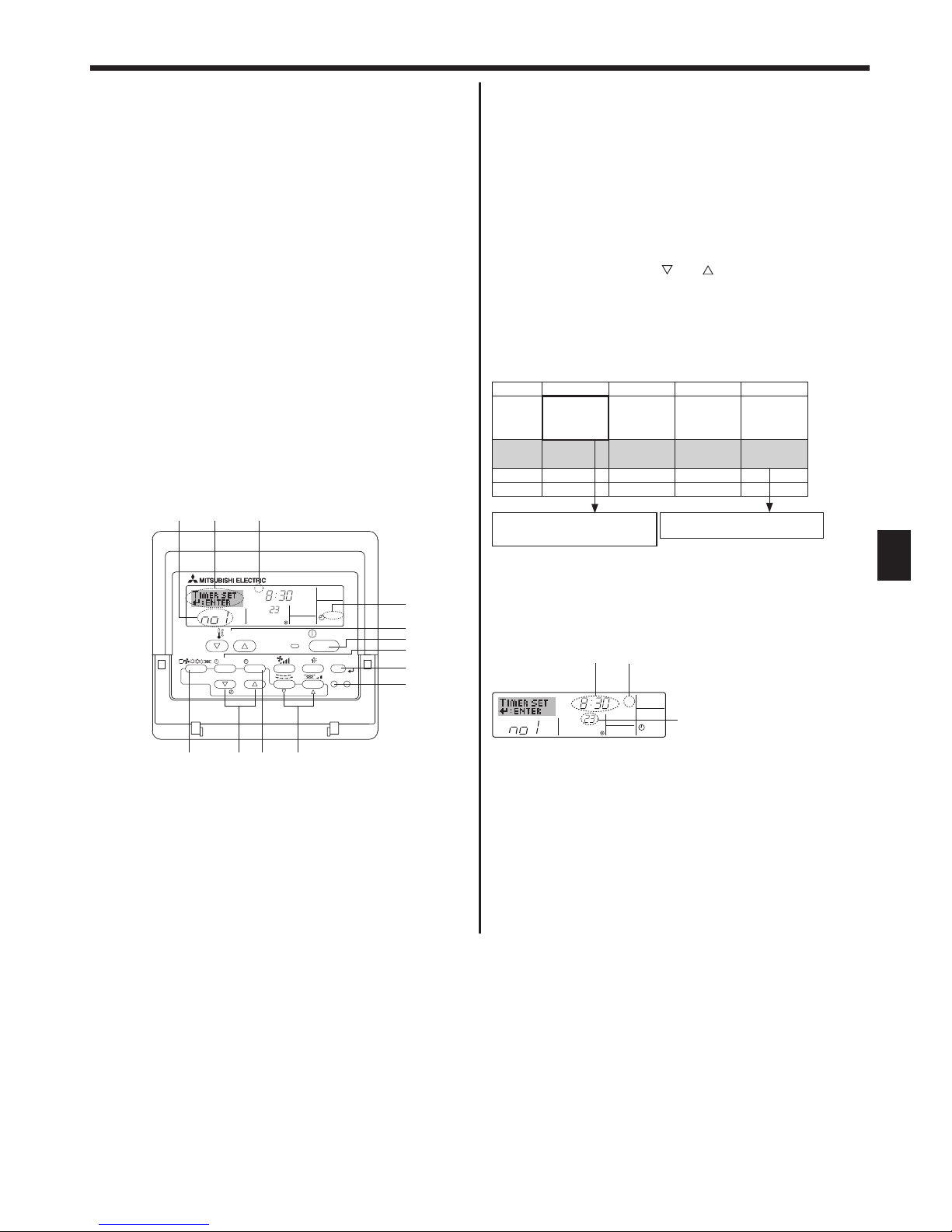
29
D
6.1. Für verdrahtete Fernbedienung
Sie können die Funktionsauswahl verwenden, um auszuwählen,
welchen der drei Timer Sie verwenden möchten: 1 Wöchentlicher Timer,
2 Einfacher Timer oder 3 Auto-Off-Timer.
6.1.1. Wöchentlicher Timer
Der wöchentliche Timer kann verwendet werden, um bis zu acht
Betriebsarten für jeden Tag der Woche einzustellen.
• Jede Betriebsart kann aus Folgendem bestehen: EIN/AUS-Zeit
zusammen mit einer Temperatureinstellung oder nur EIN/AUS-Zeit
oder nur Temperatureinstellung.
• Wenn die aktuelle Zeit eine vom Timer eingestellte Zeit erreicht,
führt die Klimaanlage die vom Timer eingestellte Aktion durch.
Die Einteilung der Zeiteinstellung für diesen Timer ist 1 Minute.
Hinweis:
*1. Der wöchentliche Timer/einfache Timer/Auto-Off-Timer können nicht
gleichzeitig eingestellt werden.
*2. Der wöchentliche Timer funktioniert nicht, wenn eine der folgenden
Bedingungen wirksam ist.
Die Timerfunktion ist ausgeschaltet; das System befindet sich in einem
unnormalen Zustand; ein Testlauf wird durchgeführt; die Fernbedienung
führt einen Selbstcheck oder einen Fernbedienungscheck durch; der
Benutzer stellt gerade eine Funktion ein; der Benutzer stellt gerade
einen Timer ein; der Benutzer stellt gerade den aktuellen Wochentag
oder die Zeit ein; das System wird zentral gesteuert. (Das System führt
insbesondere dann keine Betriebsarten durch (Gerät ein, Gerät aus oder
Temperatureinstellung), die während diesen Bedingungen deaktiviert
sind.)
°C
SUN
ON
WEEKLY
PAR-21MAA
ON/OFF
FILTER
CHECK
OPERATION
CLEAR
TEST
TEMP.
MENU
BACK DAY
MONITOR/SET
CLOCK
ON/OFF
2
42 3
a9
78
0
4
1
3
b
1
Betriebsart Nr.
Tageseinstellung
<So stellen Sie den wöchentlichen Timer ein>
1. Achten Sie darauf, dass Sie sich im Standardkontrollbildschirm
befinden und dass die Anzeige für den wöchentlichen Timer 1 auf
dem Display angezeigt wird.
2. Drücken Sie die Taste Timer-Menü 2, so dass “Set Up” auf
dem Bildschirm erscheint (unter 2). (Beachten Sie, dass mit
jedem Tastendruck die Anzeige zwischen “Set Up” und “Monitor”
umgeschaltet wird.)
3. Drücken Sie die Taste Timer Ein/Aus (Tag einstellen) 9, um den
Tag einzustellen. Mit jedem Drücken geht die Anzeige unter 3 zur
nächsten Einstellung in der folgenden Reihenfolge: “Sun Mon Tues
Wed Thurs Fri Sat” → “Sun” → ... → “Fri” → “Sat” → “Sun Mon Tues
Wed Thurs Fri Sat”...
4. Drücken Sie die Taste Betrieb
oder (7 oder 8) so oft wie nötig,
um die entsprechende Betriebsnummer auszuwählen (1 bis 8) 4.
* Mit Ihren Eingaben unter Schritt 3 und 4 wählen Sie eine der Zellen
aus der unten dargestellten Matrix.
(Die Fernbedienungsanzeige auf der linken Seite zeigt, wie
das Display aussieht, wenn Betrieb 1 für Sonntag auf die unten
angegebenen Werte eingestellt ist.)
Setup-Matrix
Betr.-Nr. Sonntag Montag ... Samstag
Nr. 1
• 8:30
• EIN
• 23 °C
Nr. 2
• 10:00
• AUS
• 10:00
• AUS
• 10:00
• AUS
• 10:00
• AUS
...
Nr. 8
Hinweis:
Durch Einstellen des Tags auf “Sun Mon Tues Wed Thurs Fri Sat”, können
Sie festlegen, dass derselbe Betrieb jeden Tag zur selben Zeit durchgeführt
wird.
(Beispiel: Betrieb 2 oben, der für jeden Tag der Woche gleich ist.)
<Einstellen des wöchentlichen Timers>
5. Drücken Sie die entsprechende Taste Zeit einstellen 1 so oft wie
nötig, um die gewünschte Zeit einzustellen (unter 5).
* Wenn Sie die Taste gedrückt halten, rückt die Zeit zuerst in
Minutenintervallen, dann in Zehn-Minuten-Intervallen und dann
in Ein-Stunden-Intervallen vor.
6. Drücken Sie die Taste ON/OFF 1, um die gewünschte Betriebsart
auszuwählen (EIN oder AUS) unter 6.
* Jedes Drücken ändert die nächste Einstellung in der folgenden
Reihenfolge: keine Anzeige (keine Einstellung) → “ON” →
“OFF”.
6. Timer
°C
SUN
ON
WEEKLY
6
7
5
Zeigt die ausgewählte Betriebsart an (EIN oder AUS)
* Erscheint nicht, wenn die Betriebsart nicht
eingestellt ist.
Zeigt die Temperatureinstellung an
* Erscheint nicht, wenn die
Temperatur nicht eingestellt ist.
Zeigt die
Zeiteinstellung an
<Einstellungen von Betrieb 1 für Sonntag>
Klimaanlage um 8.30 Uhr mit auf 23 °C
eingestellter Temperatur starten.
<Einstellung von Betrieb 2 für jeden Tag>
Klimaanlage um 10.00 Uhr ausschalten.
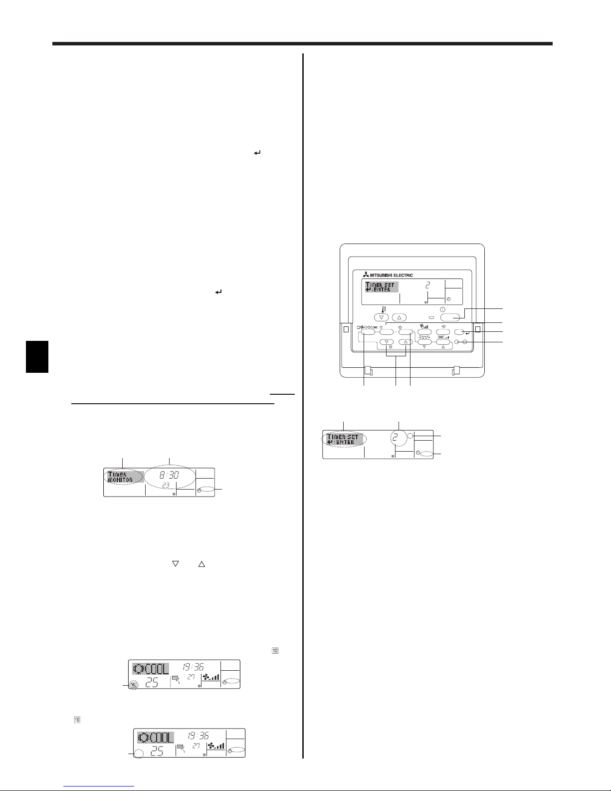
30
D
7. Drücken Sie die entsprechende Taste Temperatur einstellen 3, um
die gewünschte Temperatur einzustellen (unter 7).
* Jedes Drücken ändert die Einstellung in der folgenden
Reihenfolge: keine Anzeige (keine Einstellung) ⇔ 24 ⇔ 25 ⇔ ...
⇔ 29 ⇔ 30 ⇔ 12 ⇔ ... ⇔ 23 ⇔ keine Anzeige.
(Verfügbarer Bereich: Der Bereich für die Einstellung ist 12 °C
bis 30 °C. Der tatsächliche Bereich, über den die Temperatur
gesteuert werden kann, variiert jedoch entsprechend des Typs
des angeschlossenen Geräts.)
8. Nachdem Sie die entsprechenden Einstellungen unter Schritt 5, 6
und 7 durchgeführt haben, drücken Sie die Taste Filter 4 um die
Werte zu speichern.
Um die aktuell eingestellten Werte für den ausgewählten Betrieb
einzustellen, drücken Sie die Taste Check (Löschen) 0 einmal
kurz.
* Die angezeigte Zeiteinstellung ändert sich zu “—:—” und die
Ein/Aus- und Temperatureinstellungen verschwinden.
(Um alle wöchentlichen Timer-Einstellungen gleichzeitig zu
löschen, halten Sie die Taste Check (Löschen) 0 mindestens
2 Sekunden lang gedrückt. Das Display beginnt zu blinken,
wodurch angezeigt wird, dass alle Einstellungen gelöscht
wurden.)
Hinweis:
Ihre neuen Einträge werden storniert, wenn Sie die Taste Betriebsart
(Zurück) 2 drücken, bevor Sie die Taste Filter
4 drücken.
Wenn Sie zwei oder mehr unterschiedliche Betriebsarten für genau
dieselbe Zeit eingestellt haben, wird nur die Betriebsart mit der
höchsten Betriebsart-Nr. ausgeführt.
9. Wiederholen Sie die Schritte 3 bis 8 nach Bedarf, um so viele der
verfügbaren Zellen auszufüllen, wie Sie möchten.
10. Drücken Sie die Taste Betriebsart (Zurück) 2, um zum
Standardkontrollbildschirm zurückzukehren und den
Einstellvorgang zu beenden.
11. Um den Timer zu aktivieren, drücken Sie die Taste Timer Ein/Aus 9,
so dass die Anzeige “Timer Off” vom Bildschirm verschwindet. Achten
Sie darauf, dass die Anzeige “Timer Off” verschwunden ist.
* Wenn es keine Timer-Einstellungen gibt, blinkt die Anzeige
“Timer Off” auf dem Bildschirm.
<So zeigen Sie den wöchentlichen Timer an>
1. Achten Sie darauf, dass die wöchentliche Timer-Anzeige auf dem
Bildschirm sichtbar ist (unter 1).
2. Drücken Sie die Taste Timer-Menü 2 so dass “Monitor” auf dem
Bildschirm erscheint (unter 8).
3. Drücken Sie die Taste Timer Ein/Aus (Tag einstellen) 9 so oft wie
nötig, um den Tag einzustellen, den Sie anzeigen möchten.
4. Drücken Sie die Taste Betrieb
oder (7 oder 8) so oft wie
nötig, um den auf dem Display angezeigten Timer-Betrieb zu
ändern (unter 9).
* Mit jedem Drücken gelangen Sie zur nächsten Timer-Betriebsart
in der Reihenfolge der Zeiteinstellung.
5. Um den Monitor zu schließen und zum Standardkontrollbildschirm
zurückzukehren, drücken Sie die Taste Betriebsart (Zurück) 2.
<So schalten Sie den wöchentlichen Timer aus>
Drücken Sie die Taste Timer Ein/Aus 9, so dass “Timer Off” unter
.
erscheint.
<So schalten Sie den wöchentlichen Timer ein>
Drücken Sie die Taste Timer Ein/Aus 9, so dass die Anzeige “Timer Off”
(unter ) verschwindet.
6.1.2. Einfacher Timer
Sie haben drei Möglichkeiten, den einfachen Timer einzustellen.
• Nur Startzeit:
Die Klimaanlage startet, wenn die eingestellte Zeit vergangen ist.
• Nur Stoppzeit:
Die Klimaanlage stoppt, wenn die eingestellte Zeit vergangen ist.
• Start- und Stoppzeiten:
Die Klimaanlage startet und stoppt, wenn die entsprechenden
Zeiten vergangen sind.
Der einfache Timer (Start und Stopp) kann nur einmal innerhalb eines
Zeitraums von 72 Stunden eingestellt werden. Die Zeiteinstellung
erfolgt in Stunden-Schritten.
Hinweis:
*1. Der wöchentliche Timer/einfache Timer/Auto-Off-Timer können nicht
gleichzeitig eingestellt werden.
*2. Der einfache Timer funktioniert nicht, wenn eine der folgenden
Bedingungen wirksam ist:
Die Timerfunktion ist ausgeschaltet; das System befindet sich in einem
unnormalen Zustand; ein Testlauf wird durchgeführt; die Fernbedienung
führt einen Selbstcheck oder eine Diagnose durch; der Benutzer wählt
gerade eine Funktion aus; der Benutzer stellt gerade den Timer ein; das
System wird zentral gesteuert. (Unter diesen Bedingungen ist der Ein/
Aus-Betrieb deaktiviert.)
<So stellen Sie den einfachen Timer ein>
1. Achten Sie darauf, dass Sie sich im Standardkontrollbildschirm
befinden und dass die Anzeige des einfachen Timers auf dem Display
angezeigt wird (unter 1).
Wenn etwas anderes als der einfache Timer angezeigt wird, stellen
Sie den SIMPLE TIMER mit Hilfe der Timer-Funktionseinstellung der
Funktionsauswahl ein (siehe 8.[4]–3 (3)).
2. Drücken Sie die Taste Timer-Menü 2, so dass “Set Up” auf
dem Bildschirm erscheint (unter 2). (Beachten Sie, dass mit
jedem Tastendruck die Anzeige zwischen “Set Up” und “Monitor”
umgeschaltet wird.)
3. Drücken Sie die Taste ON/OFF 1, um die aktuelle EIN- oder AUSEinstellung des einfachen Timers anzuzeigen. Drücken Sie die Taste
einmal, um die restliche Zeit unter EIN anzuzeigen, und dann noch
einmal, um die restliche Zeit unter AUS anzuzeigen. (Die Anzeige
EIN/AUS erscheint unter 3.)
• “EIN”-Timer:
Die Klimaanlage startet den Betrieb, wenn die angegebene Anzahl
Stunden vergangen ist.
• “AUS”-Timer:
Die Klimaanlage stoppt den Betrieb, wenn die angegebene Anzahl
Stunden vergangen ist.
4. Wenn “ON” oder “OFF” unter 3 angezeigt wird: Drücken Sie die
entsprechende Taste Zeit einstellen 1 so oft wie nötig, um die
Stunden auf EIN (falls “ON” angezeigt wird) oder die Stunden auf AUS
(falls “OFF” angezeigt wird) unter 4 einzustellen.
• Verfügbarer Bereich: 1 bis 72 Stunden
5. Um sowohl die Zeiten für EIN als auch für AUS einzustellen,
wiederholen Sie die Schritte 3 und 4.
* Beachten Sie, dass die AUS- und EIN-Zeiten nicht auf denselben
Wert eingestellt werden können.
6. So löschen Sie die aktuelle EIN- oder AUS-Einstellung: Zeigen Sie
die EIN- oder AUS-Einstellung (siehe Schritt 3) an und drücken Sie
dann die Taste Check (Löschen) 0, so dass die Zeiteinstellung zu
“—” unter 4 zurückkehrt. (Wenn Sie nur eine EIN-Einstellung oder
nur eine AUS-Einstellung verwenden wollen, achten Sie darauf, dass
die Einstellung, die Sie nicht verwenden möchten, als “—” angezeigt
wird.)
ONHr
AFTER
SIMPLE
PAR-21MAA
ON/OFF
FILTER
CHECK
OPERATION
CLEAR
TEST
TEMP.
MENU
BACK DAY
MONITOR/SET
CLOCK
ON/OFF
2a9
0
4
1
b
ONHr
AFTER
SIMPLE
4
1
3
2
Timer-Einstellung
Aktion (Ein oder Aus)
* “— —” wird angezeigt, wenn es
keine Einstellung gibt.
°C
°C
TIME SUN
WEEKLY
0
6. Timer
°C
TIMER
SUN
ON
OFF
WEEKLY
1
9
8
°C
°C
TIME SUN
WEEKLY
0
Timer-Einstellungen
 Loading...