

Mitsubishi Electric City Multi PKFY, City Multi PKFY-P08NBMU-E, City Multi PKFY-P06NBMU-ER1, City Multi PKFY-P06NBMU-E, City Multi PKFY-P08NBMU-ER1 Service Manual
SPLIT-TYPE, HEAT PUMP AIR CONDITIONERS
TECHNICAL & SERVICE MANUAL
R22R410A
Indoor unit
[Model names] [Service Ref.]
PKFY-P06NBMU-E
PKFY-P06NBMU-E
PKFY-P06NBMU-ER1
PKFY-P08NBMU-E
PKFY-P08NBMU-E
PKFY-P08NBMU-ER1
September 2012
No. OCH461
REVISED EDITION-B
Revision:
• "8-2. Function of Dip
switch" has been modified.
• Some descriptions have
been modified.
• Please void OCH461
REVISED EDITION-A.
Note:
• This manual describes only
service data of the indoor
units.
• RoHS compliant products
have <G> mark on the
spec name plate.
INDOOR UNIT
Model name
indication
CONTENTS
1. TECHNICAL CHANGES
2. PART NAMES AND FUNCTIONS
3. SPECIFICATION
4. OUTLINES AND DIMENSIONS
5. WIRING DIAGRAM
6. REFRIGERANT SYSTEM DIAGRAM
7. MICROPROCESSOR CONTROL
8. TROUBLESHOOTING
9. DISASSEMBLY PROCEDURE
.....................................
.........................
.................................
..........................
.............
PARTS CATALOG (OCB461)
..........
..............
..........
.........
2
2
5
7
8
9
10
15
23
Use the specifi ed refrigerant only
OCH461B
Never use any refrigerant other than that specifi ed.
Doing so may cause a burst, an explosion, or fi re when the unit is being used, serviced, or disposed of.
Correct refrigerant is specifi ed in the manuals and on the spec labels provided with our products.
We will not be held responsible for mechanical failure, system malfunction, unit breakdown or accidents caused
by failure to follow the instructions.
1
TECHNICAL CHANGES
PKFY-P06NBMU-E PKFY-P06NBMU-ER1
PKFY-P06NBMU-E PKFY-P06NBMU-ER1
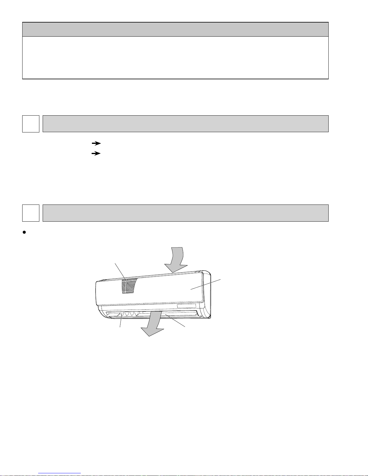
HEAT EXCHANGER and WATER CUT have been changed.
2
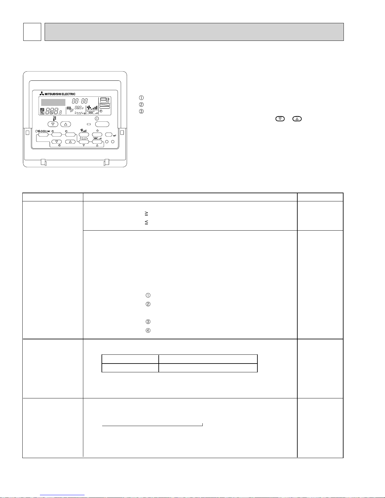
PART NAMES AND FUNCTIONS
Indoor unit
Air intake
Filter
Grille
Louver
Vane
Air outlet
2
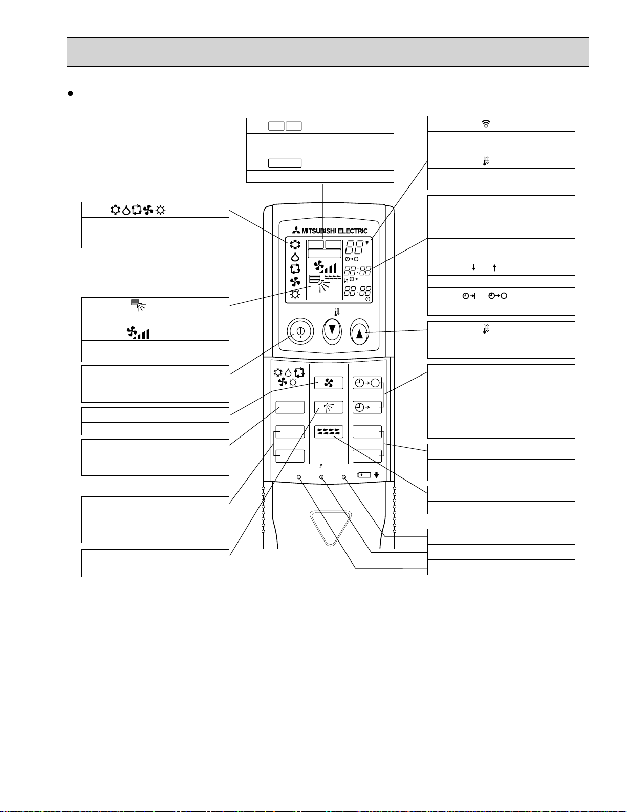
Wireless remote controller
OCH461B
display
OPERATION MODE display
Operation mode display indicates which
operation mode is in effect.
display
The vertical direction of air flow is indicated.
display
FAN SPEED display indicates which fan
speed has been selected.
ON/OFF button
The unit is turned ON and OFF alternately
each time the button is pressed.
FAN SPEED SELECT button
Used to change the fan speed.
MODE SELECT button
Used to switch the operation mode between
cooling, drying, fan, heating and auto mode.
+ In case the outdoor unit is cool only type, the
heating and auto mode are not available.
CHECK-TEST RUN button
Only press this button to perform an
inspection check or test operation.
Do not use it for normal operation.
VANE CONTROL button
Used to change the air flow direction.
CHECK
TEST RUN
display
CHECK and TEST RUN display indicate that
the unit is being checked or test-run.
MODEL SELECT
Blinks when model is selected.
display
CHECK
TEST RUN
MODEL SELECT
NOT AV AILABLE
°F
°C
AMPM
AMPM
ON/OFF TEMP
MODE
CHECK
TEST RUN
FAN
VANE
LOUVER
RESETSET CLOCK
AUTO STOP
AUTO START
h
min
display
Lights up while the signal is transmitted to
the indoor unit when the button is pressed.
display
SET TEMP. display indicates the set desired
temperature.
CLOCK display
Displays the current time.
TIMER display
Displays when in timer operation or when
setting timer.
“ ” “ ” display
Displays the order of timer operation.
“ ” “ ” display
Displays whether timer is on or off.
button
SET TEMPERATURE button sets any desired
room temperature.
TIMER CONTROL buttons
AUTO STOP (OFF timer): when this switch is
set, the air conditioner will be automatically
stopped at the preset time.
AUTO START (ON timer): when this switch is
set, the air conditioner will be automatically
started at the preset time.
h and min buttons
Buttons used to set the “hour and minute” of
the current time and timer settings.
LOUVER button
Changes left/right airflow direction.
(Not available for this model.)
CLOCK button
RESET button
SET button
33
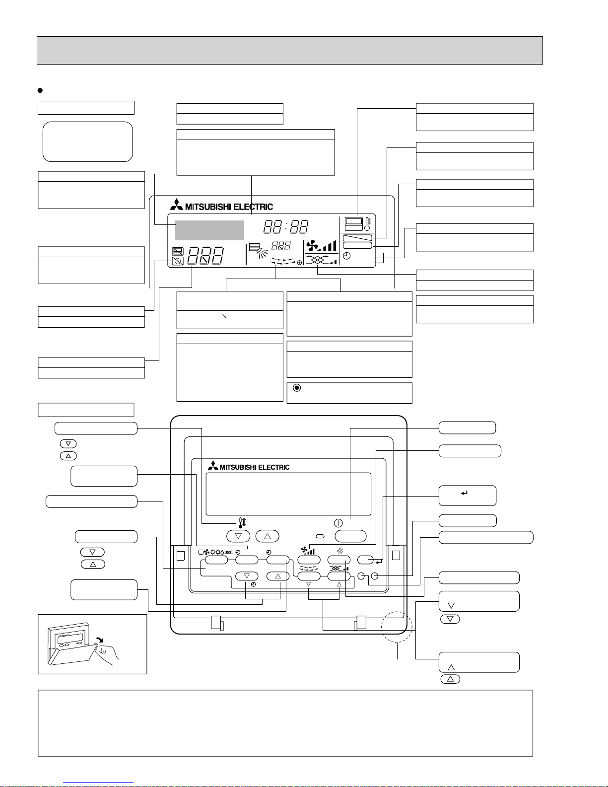
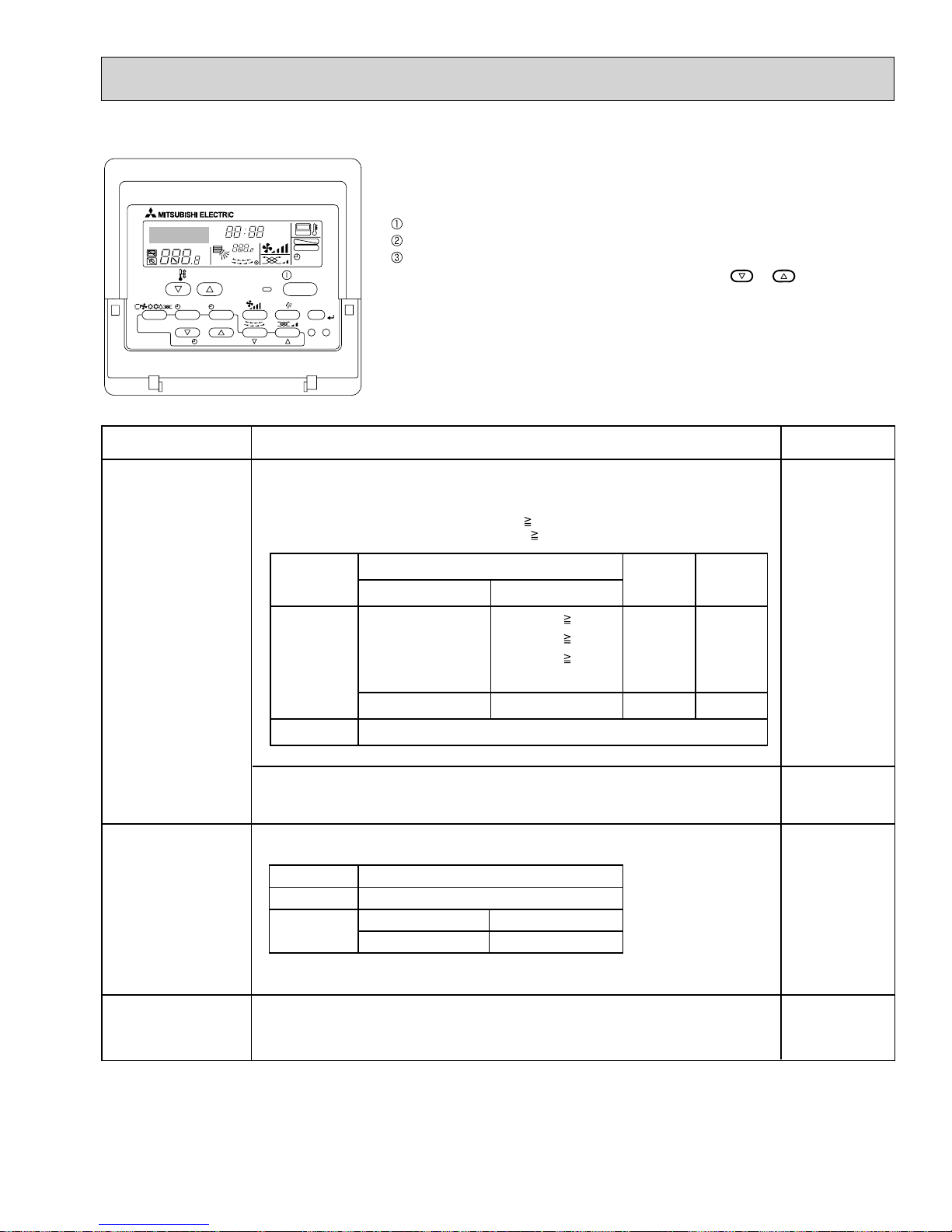
Wired remote controller
OCH461B
Display Section
For purposes of this explanation,
all parts of the display are shown.
During actual operation, only
the relevant items will be lit.
Identifies the current operation
Shows the operating mode, etc.
*Multilanguage display is available.
“Centrally Controlled” indicator
Indicates that operation from the
remote controller has been prohibited by a master controller.
“Timer is Off” indicator
Indicates that the timer is off.
Temperature Setting
Shows the target temperature.
Operation Section
Temperature setting buttons
Down
Up
Timer Menu button
(Monitor/Set button)
Mode button (Return button)
Day-of-Week
Shows the current day of the week.
Time/Timer Display
Shows the current time, unless the simple or Auto Off
timer is set.
If the simple or Auto Off timer is set, the time to be
switched off is shown.
TIME SUN MON TUE WED THU FRI SAT
TIMER
AFTER
ERROR CODE
°F°C
Hr
AFTER
°F°C
ONLY1Hr.
Up/Down Air Direction indicator
The indicator shows the direction of the outcoming airflow.
“One Hour Only” indicator
Displays if the airflow is set to
Low or downward during COOL
or DRY mode. (Operation varies
according to model.)
The indicator goes off in one hour,
at which time the airflow direction
also changes.
Room Temperature display
Shows the room temperature. The room
temperature display range is 46–102°F.
The display blinks if the temperature
is less than 46°F or 102°F or more.
Louver display
Indicates the action of the swing louver.
Does not appear if the louver is not
running.
(Power On indicator)
Indicates that the power is on.
ON
OFF
FUNCTION
FILTER
WEEKLY
SIMPLE
AUTO OFF
“Sensor” indication
Displays when the remote controller
sensor is used.
“Locked” indicator
Indicates that remote controller buttons have been locked.
“Clean The Filter” indicator
To be displayed on when it is time to
clean the filter.
Timer indicators
The indicator comes on if the corresponding timer is set.
Fan Speed indicator
Shows the selected fan speed.
Ventilation indicator
Appears when the unit is running in
Ventilation mode.
ON/OFF button
Fan Speed button
Filter button
(<Enter> button)
Set Time buttons
Back
Ahead
Timer On/Off button
(Set Day button)
Opening the
cover
Note:
●
“PLEASE WAIT” message
This message is displayed for approximately 3 minutes when power is supplied to the indoor unit or when the unit is recovering from a power failure.
●
“NOT A V AILABLE” message
This message is displayed if an invalid button is pressed (to operate a function that the indoor unit does not have).
If a single remote controller is used to operate multiple indoor units simultaneously that are different types, this message will not be displayed as
far as any of the indoor units is equipped with the function.
TEMP.
MENU
MONITOR/SET
BACK DAY
PAR-21MAA
CLOCK
ON/OFF
OPERATION
Built-in temperature sensor
4
ON/OFF
FILTER
CHECK
CLEAR
TEST
Test Run button
Check button (Clear button)
Airflow Up/Down button
Louver button
( Operation button)
T o return operation
number
Ventilation button
( Operation button)
To go to next operation
number

3
OCH461B
SPECIFICATION
3-1. Specifi cations
Service Ref.
Power source
Cooling capacity
(Nominal)
Power input
Current input
Heating capacity
(Nominal )
Power input
Current input
External finish
External dimension H × W × D
Net weight
Heat exchanger
Fan
Type × Quantity
External
static press.
Motor type
Motor output
Driving mechanism
Airflow rate
(Low-Mid2-Mid1-High)
Noise level (Low-Mid2-Mid1-High)
(measured in anechoic room)
Insulation material
Air filter
Protection device
Refrigerant control device
Connectable outdoor unit
Diameter of
refrigerant pipe
Liquid
Gas
(R410A)
(R410A)
Field drain pipe size
Standard
attachment
Optional parts
Remarks
Document
Accessory
External heater adapter
Installation
*1
*1
*2
*2
(R22)
(R22)
kW
Btu/h
kW
A
kW
Btu/h
kW
A
mm
in.
kg (lb)
Pa
mmH
2
kW
3
/min
m
L/s
cfm
dB <A>
mm (in.)
mm (in.)
mm (in.)
PKFY-P06NBMU-E
PKFY-P06NBMU-ER1
PKFY-P08NBMU-E
PKFY-P08NBMU-ER1
1-phase 208/230V 60Hz
1.8
6,000
0.03
0.15
2.0
6,700
0.03
0.15
2.3
8,000
0.03
0.15
2.6
9,000
0.03
0.15
Plastic, MUNSELL (1.0Y 9.2/0.2)
295 × 815 × 225
11-5/8" × 32-1/8" × 8-7/8"
10 (22)
Cross fin (Aluminum fin and copper tube)
Line flow fan × 1
0
O
0
1-phase induction motor
0.008
Direct-driven by motor
4.9 - 5.2 - 5.6 - 5.9
82 - 87 - 93 - 98
170 - 180 - 200 - 210
32 - 33 - 35 -36
4.9 - 5.2 - 5.6 - 5.9
82 - 87 - 93 - 98
170 - 180 - 200 - 210
32 - 33 - 35 -36
Polyethylene sheet
PP honeycomb
Fuse
LEV
R410A, R22 CITY MULTI
ø6.35 (ø1/4")
ø6.35 (ø1/4")
ø12.7 (ø1/2")
ø12.7 (ø1/2")
Flare
Flare
Flare
Flare
ø6.35 (ø1/4")
ø6.35 (ø1/4")
ø12.7 (ø1/2")
ø12.7 (ø1/2")
Flare
Flare
Flare
Flare
I.D. 16mm (5/8")
Installation Manual, Instruction Book
MA remote controller cable
PAC-SA88HA-E
Details on foundation work, insulation work, electrical wiring, power source switch, and other items shall be referred to
the Installation Manual.
Note :
Pipe length :
Level difference :
* Due to continuing improvement, above specification may be subject to change without notice.
*1 Nominal cooling conditions
Indoor :
Outdoor :
80°FDB/67°FWB (26.7°CDB/19.4°CWB)
95°FDB (
25 ft. (7.6 m)
0 ft (
35°CDB)
0 m)
*2 Nominal heating conditions
70°FDB(21°CDB)
47°FDB/43°FWB (8.3°CDB/6.1°CWB)
25 ft. (7.6 m)
0 ft (0 m)
55
Unit converter
kcal/h = kW × 860
Btu/h = kW × 3,412
3
cfm = m
lb = kg/0.4536
*Above specification data is
subject to rounding variation.
/min × 35.31
3-2. Electrical parts specifi cations
OCH461B
Service Ref.
Parts name
Room temperature
thermistor
Liquid pipe thermistor
Gas pipe thermistor
Fuse
(Indoor controller board)
Fan motor
(with thermal fuse)
Fan motor capacitor
Vane motor
(with limit switch)
Linear expansion valve
Power supply terminal
block
Transmission terminal
block
MA remote controller
terminal block
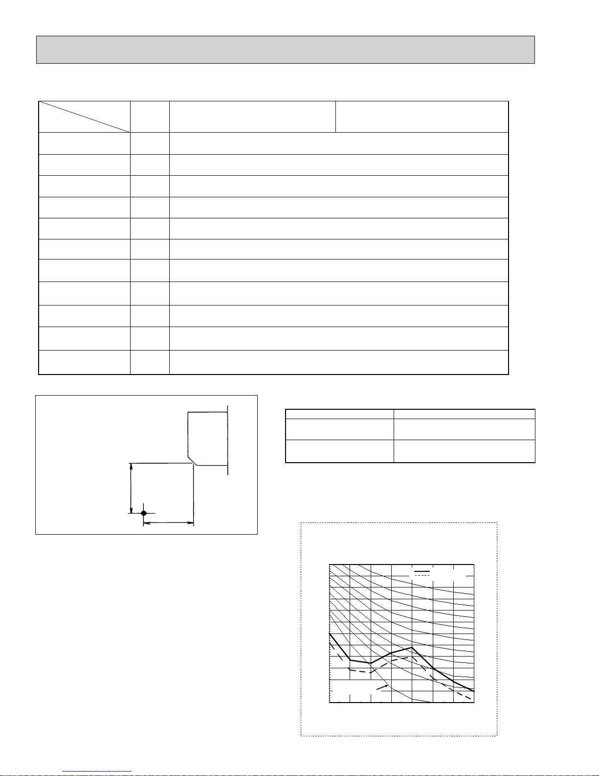
3-3. Sound levels
Symbol
TH21
TH22
TH23
FUSE
MF
C1
MV
LEV
TB2
TB5
TB15
PKFY-P06NBMU-E
PKFY-P06NBMU-ER1
PKFY-P08NBMU-E
PKFY-P08NBMU-ER1
Resistance 30°F/15.8k, 50°F/9.6k, 70°F/6.0k, 80°F/4.8k, 90°F/3.9k, 100°F/3.2k
Resistance 30°F/15.8k, 50°F/9.6k, 70°F/6.0k, 80°F/4.8k, 90°F/3.9k, 100°F/3.2k
Resistance 30°F/15.8k, 50°F/9.6k, 70°F/6.0k, 80°F/4.8k, 90°F/3.9k, 100°F/3.2k
250V 6A
4-Pole Output 8W / PS4N8-KB
1.2 × 440V
MSFBC20 DC12V
DC12V Stepping motor drive
Port :3.2 (0~2000pulse)
(L1, L2, GR) 250V 20A
(M1, M2, S) 250V 20A
(1, 2) 250V 10A
Service Ref.
Sound level at anechoic room : Low-Middle2-Middle1-High
PKFY-P06NBMU-E
PKFY-P06NBMU-ER1
PKFY-P08NBMU-E
PKFY-P08NBMU-ER1
Sound level dB (A)
32-33-35-36
32-33-35-36
3.3 ft.
(1m)
3.3 ft.
Measurement location
* Measured in anechoic room.
(1m)
3-4. NC curve
PKFY-P06/08NBMU-E(R1)
External static pressure : 0Pa
Power source : 208,230V, 60Hz
70.0
MPa
65.0
60.0
55.0
50.0
45.0
40.0
35.0
30.0
25.0
20.0
Approximate minimum
audible limit on
15.0
continuous noise
10.0
OCTAVE BAND PRESSURE LEVEL (dB) 0dB = 20
63 125 250 500 1k 2k 4k 8k
OCTAVE BAND CENTER FREQUENCIES(Hz)
6
High speed
Low speed
NC60
NC50
NC40
NC30
NC20
4
OCH461B
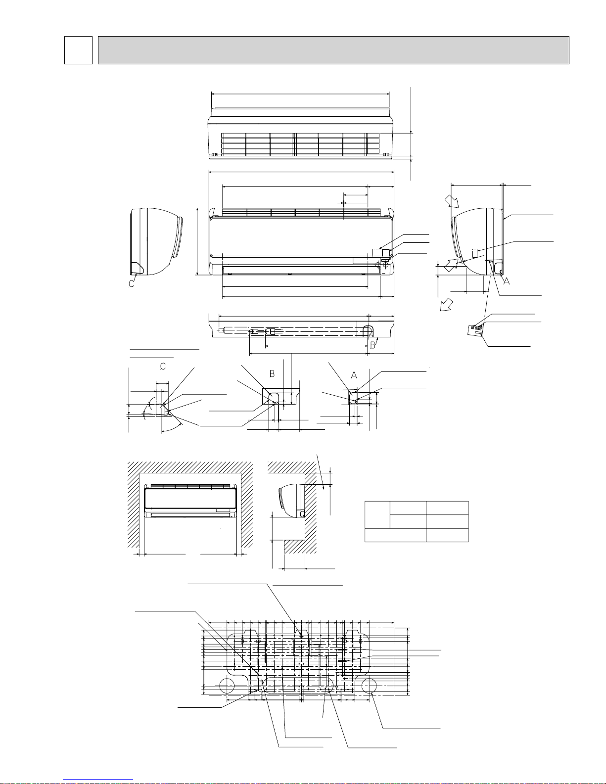
OUTLINES AND DIMENSIONS
PKFY-P06NBMU-E
PKFY-P08NBMU-E
PKFY-P06NBMU-ER1
PKFY-P08NBMU-ER1
Detailed figure dwg (ABC)
(Knockout hole)
2-1/8(54)
31/32(24.4)
13/32(10) 1-25/32(45)
3°
5°
R19/32(R15)
R19/32(R15)
R5/16(R8)
45°
Required space
11-5/8(295)
Knockout hole for
left piping
Knockout holt for
under piping
Knockout hole of
remote control wiring
30-13/16(783)
32-1/8(815)
25-3/16(640)
Air intake
25-3/16(640)
26-31/32(660)(Drain pipe total 29-29/32(760))
R19/32(R15)
R5/16(R8)
13/32(10)
3/32(2.5)
5/8(16)
2-3/8(60mm) or more for
left and left back piping.
27-3/8(695)
17-23/32(450)
20-25/32(520)
1-31/32(50)
3-19/32(91.5)1-25/32(45)
Air intake
Air outlet
Liquid pipe
R15/32(R12)
R5/16(R8)
13/32(10)
1-11/32(34)
4-3/16(106.7)
1/8(3)
Gas pipe
4-1/2(115)
2-3/8
(60)
4-11/32(110)
4-9/16(116)
Knockout hole of
right piping
Knockout hole for
remote control wiring
5/32(4) 1-31/32(50)
3/32(2.5) 5/8(16)
Air intake
3-15/16(100.6)17/32(14)
Air intake
(Direction)
Power supply
Transmission
Address board
Air outlet
(Direction)
8-7/8(225) 3/16(5)
Air intake
(Direction)
2-7/8
(74.6)
1-7/16(37.8)
Air outlet
Air outlet
Address board
Detailed
Unit : inch (mm)
installaion plate
Terminal block
1/4
(7)
Air intake
Address board
Connection No.
Address setting digit
Mode selection
*3 Address board is protected
by a plastic cover.
Remove the screw holding
the cover with screw-driver
at the time of address setting.
Min55/64(22) Min25/32(20)
Installation plate balance point hole
3/16×1-3/8(4.5×35) 4 holes
Installation plate
6-1/4(159)
5-1/4(133)
4-13/16(122.5)
3-27/32(97.5)
3-11/32(85)
2-27/32(72.5)
2-3/8(60)
1-7/8(47.5)
7/8(22.5)
0
19/32(15)
3-17/32(90)
4-1/32(102.5)
4-7/8(124)
8-:5/32(:4.3) holes
12-29/32(328)
16-1/32(407.5)
12-29/32(328)
11-5/8(295)
10-1/4(260)
9-1/4(235)
Min3-15/16(100)
Details of installation plate
0
8-27/32(225)
7-15/32(190)
6-3/32(155)
6-1/4(159)
6-7/8(175)
8-1/16(205)
6-11/16(170)
4-23/32(120)
1-3/16(30)
3-11/32(85)
1-3/16(30)
0
13/32(10)
13/32(10)
Knock of hole
12-:1/8(:2.8)holes
4-:11/32(:9)holes
Min1-31/32(50)
Min3-35/64(90)
4-23/32(120)
3-11/32(85)
1-3/4(45)
1-23/32(44)
1-31/32(50)
Note 1. Use M10 or W3/8 screw for installation plate.
Note 2. Extension piping side.
Note 3. In case of connecting MA-remote controller, please use
MA-remote controller cable in an accessories to the connector.
1/4F(:6.35)
1/2F(:12.7)
:5/8(:16) I.D
6-5/8(168)
5-5/16(135)
4-29/32(125)
4-11/32(110)
1-3/8(35)
13/32(10)
0
1-3/32(27.5)
1-9/16(40)
2-3/32(53)
2-9/16(65)
3-7/16(87)
4-7/16(113)
5-1/32(128)
7-3/32(180)
7-15/32(190)
8-27/32(225)
6-3/32(155)
6-7/8(175)
8-1/16(205)
6-11/16(170)
Refrigerart
piping
Liquid pipe
Drain pipe
11-23/32(298)
10-1/4(260)
3/16×1-15/32(4.5×37) 4 holes
3/16×1-9/16(4.5×40) 4 holes
9-1/4(235)
11-23/32(298)
Piping hole:2-9/16(:65)
Gas pipe
16-1/32(407.5)
87-:3/16(:5.1)holes
77
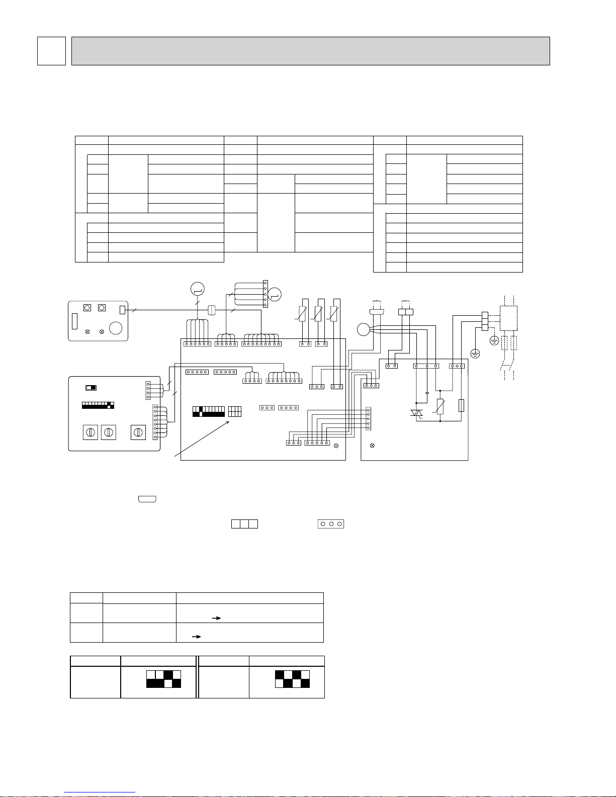
WIRING DIAGRAM5
OCH461B
PKFY-P06NBMU-E PKFY-P08NBMU-E
PKFY-P06NBMU-ER1 PKFY-P08NBMU-ER1
Legend
Symbol
I.B
CN32
CN51
CN52
Indoor controller board
Connector
Name
Remote switch
Centrally control
Remote indication,
External heater
Capacity code
Mode selection
P.B
SW2
Switch
SW3
Indoor power board
ZNR Varistor
Fuse (6A 250V)
FUSE
F.C
Fan phase control
Capacitor (Fan motor)
C1
M
LEV
W.B
SW2SW1
RU
LED2
LED1
9
CNB
BZ
6
YLW
WHT
ORN
11
CN60
LEV
(WHT)
A.B
SW5
208V 230V
SW1
ON
OFF
1234567891
0
1
9
2
8
3
7
4
6
5
10ths
DIGIT1sDIGIT
Note
0
1
9
8
7
4
6
5
0
2
3
(RED)
ADDRESS
CN43
(RED)
ADDRESS
CN82
SW14SW11SW12
F
E
D
C
B
A
BRANCH
No.
4
1
0
1
2
3
4
5
6
7
8
9
8
1
See Fig.1
4
8
ON
OFF
123456789
I.B
1. At servicing for outdoor unit, always follow the wiring diagram of outdoor unit.
2. In case of using MA-remote controller, please connect MA-remote controller cable in an accessory
to the connector . (Remote controller wire is non-polar.)
12
3. In case of using M-NET, please connect to TB5 (Transmission line is non-polar.)
4. Symbols used in wiring diagram above are, : terminal block, : connector
5. The setting of the SW2 dip switches differs in the capacity. For the detail, refer to the Fig. 1.
6. Please set the switch SW5 according to the power supply voltage.
Set SW5 to 230V side when the power supply is 230 volts.
When the power supply is 208 volts, set SW5 to 208V side.
Symbol
MF Fan motor
MV
LEV
TB2
TB5
TH21
TH22
TH23
5
9
BLU
BRN
RED
CN5V
VANE
(BLU)
1515
CN52CN51
SW2SW3
1234
10
Vane motor
Linear expansion valve
Terminal
block
Thermistor
RED
1
WHT
BLU
M
ORN
YLW
5
MV
56
141 8
CN42
ADDRESS
(RED)
CN90
WIRELESS
(WHT)
CN32
91
CN81
ADDRESS
(RED)
14
13
Power supply
Room temp.detection
(32°F/15k
t° t° t°
CN41
CN35M
(BLU)
Name
Symbol
A.B
Transmission
,77°F/5.4k)
W.B
Pipe temp.detection/Liquid
(32°F/15k,77°F/5.4k)
Pipe temp.detection/Gas
(32°F/15k,77°F/5.4k)
TO MA-REMOTE
TH23 TH22
2
CN29
GAS
(BLK)
ORN
13
CN3A
MA-
REMOCON
(BLU)
13
5
CN53M
(RED)
112
CN21
LIQUID
(WHT)
ORN
1
TH21
12
CN20
INTAKE
(RED)
LED2
CONTROLLER
DC8.7-13V
1
2
M
1~
MF
13
CN35P
(BLU)
5
CN53P
(RED)
1
LED1
P.B
Address board
Name
SW1
SW5
SW11
SW12
SW14
Switch
Mode selection
Voltage selection
Address setting 1s digit
Address setting 10ths digit
Branch No.
Wireless remote controller board
Receving unit
RU
Buzzer
BZ
LED1 LED(Operation indicator:Green)
(Preparation for heating:Orange)
LED
LED2
SW1
Emergency operation (Heat)
Emergency operation (Cool)
SW2
TO OUTDOOR UNIT
BC CONTROLLER
M-NET REMOTE CONTROLLER
DC24-30V
M1M2
TB5
BLU
BLU
RED
WHT
FAN
(GRN)
12
146
CN2M
M-NET
(BLU)
C1
ZNR
F.C
RED
BLK
BLU
13
CND
(RED)
FUSE
250V
6A
U
<+>
TB2
L1
L2
GR
GRN /YLW
BREAKER
(16A)
TO NEXT
INDOOR UNIT
POWER SUPPLY
208/230V 60Hz
PULL
BOX
FUSE
(16A)
LED on indoor board for service
Mark Meaning
Main power supply
LED1
Power supply for
LED2
MA-Remote controller
Main power supply (indoor unit: 208-230V)
power on lamp is lit
Power supply for MA-Remote controller
on lamp is lit
<Fig. 1>
MODELS SW2
P06
ON
OFF
1234
<+ >Use copper supply wires.
Function
MODELS SW2
P08
ON
OFF
1234
8
6
OCH461B
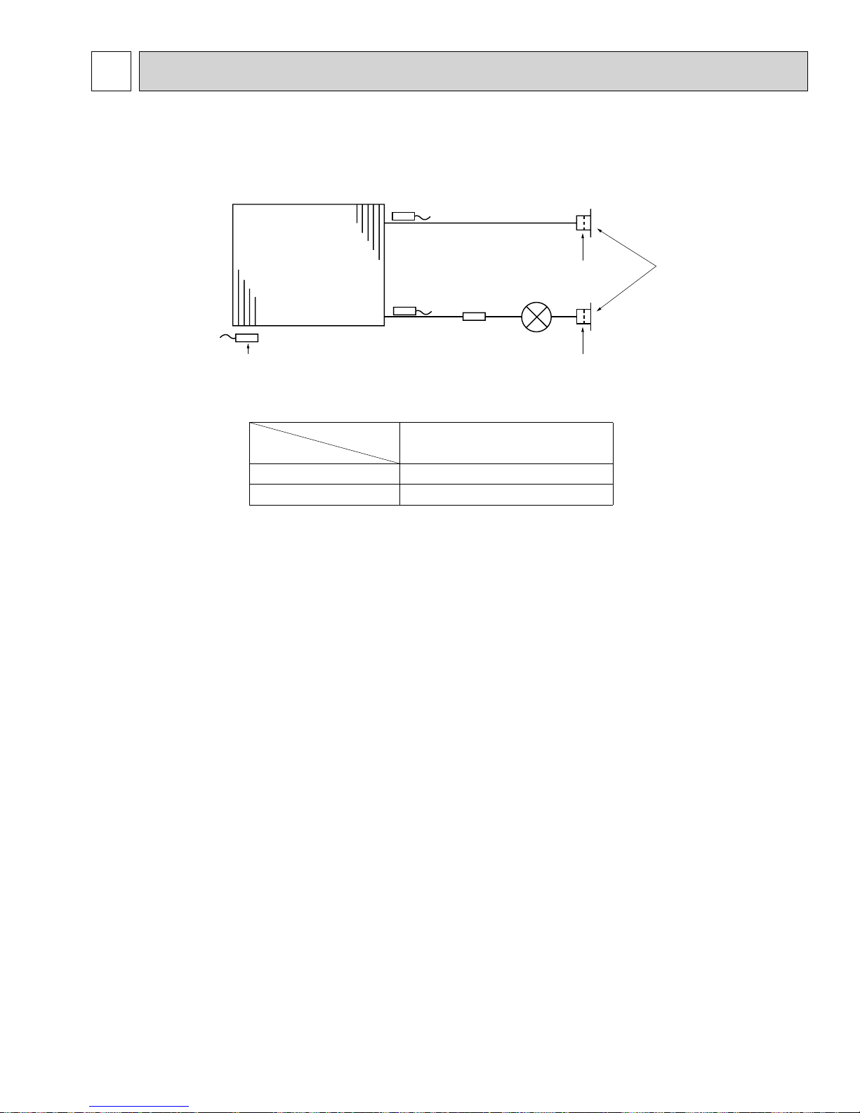
REFRIGERANT SYSTEM DIAGRAM
PKFY-P06NBMU-E PKFY-P08NBMU-E
PKFY-P06NBMU-ER1 PKFY-P08NBMU-ER1
Gas pipe temperature thermistor
TH23
Gas pipe
Heat exchanger
Room temperature thermistor
TH21
Service ref.
Item
Gas pipe {12.7 (1/2”)
Liquid pipe {6.35 (1/4”)
Liquid pipe temperature thermistor
TH22
Strainer
(#100mesh)
Linear expansion
valve
Unit: mm(inch)
PKFY-P06/08NBMU-E
PKFY-P06/08NBMU-ER1
Strainer
(#100mesh)
Liquid pipe
Strainer
(#100mesh)
Flare
9
7
OCH461B
MICROPROCESSOR CONTROL
INDOOR UNIT CONTROL
7-1. COOL OPERATION
TEMP.
MENU
MONITOR/SET
BACK DAY
PAR-21MAA
Control modes
1. Thermo stat
function
TIME SUN MON TUE WED THU FRI SAT
TIMER
AFTER
ERROR CODE
ûF ûC
ONLY1Hr.
ON/OFF
CLOCK
<How to operate>
ON
OFFHrAFTER
ûF ûC
FUNCTION
FILTER
WEEKLY
SIMPLE
AUTO OFF
ON/OFF
Press POWER ON/OFF button.
Press the operation MODE button to display COOL.
Press the TEMP. button to set the desired temperature.
NOTE: The set temperature changes 2°F when the or button is
pressed one time. Cooling 67 to 87°F
FILTER
CHECK
TEST
OPERATION
CLEAR
Control details
1-1. Thermo stat function (Function to prevent restarting for 3 minutes)
• Room temperature desired temperature + 2°F
• Room temperature desired temperature
···Thermo ON
···Thermo OFF
1-2. Anti-freezing control
Detected condition : When the liquid pipe temp. (TH22) is 32°F or less in 16
minutes from compressors start up, anti-freezing control
starts and the thermo OFF.
Released condition : The timer which prevents reactivating is set for 3 minutes,
and anti-freezing control is cancelled when any one of the
following conditions is satisfied.
Liquid pipe temp. (TH22) turns 50°F or above.
The condition of the thermo OFF has become complete
by thermo stat, etc.
The operation modes became mode other than COOL.
The operation stopped.
Remarks
2. Fan
By the remote controller setting (switch of 4 speeds)
Type
4 speeds type
3. Vane
(up/down vane change)
(1) Initial setting: Start at COOL mode and horizontal vane.
(2) Vane position:
Horizontal →Downward A →Downward B →Downward C
→
(3) Restriction of the downward vane setting
When setting the downward vane A, B or C in [Mid] or [Low] of the fan speed
notch, the vane changes to horizontal position after 1 hour have passed.
Fan speed notch
[Low], [Mid2], [Mid1], [High]
· "ONLY 1 Hr"
appears on the
wired remote
controller.
10
7-2. DRY OPERATION
OCH461B
TEMP.
MENU
BACK DAY
MONITOR/SET
PAR-21MAA
Control modes
1. Thermo stat
function
TIME SUN MON TUE WED THU FRI SAT
TIMER
AFTER
ERROR CODE
ûF ûC
ONLY1Hr.
ON/OFF
CLOCK
<How to operate>
ON
OFFHrAFTER
FUNCTION
ûF ûC
FILTER
WEEKLY
SIMPLE
AUTO OFF
ON/OFF
Press POWER ON/OFF button.
Press the operation MODE button to display DRY.
Press the TEMP. button to set the desired temperature.
NOTE: The set temperature changes 2°F when the or button is
pressed one time. Dry 67 to 87°F
FILTER
CHECK
TEST
OPERATION
CLEAR
Control details
1-1. Thermo stat function (Function to prevent restarting for 3 minutes)
Setting the Dry thermo by the thermo stat signal and the room
temperature (TH21).
Dry thermo ON Room temperature desired temperature + 2°F
Dry thermo OFF Room temperature desired temperature
Room
temperature
Over 64°F
3 min. passed since starting operation
Thermo stat signal
Room temperature (T1)
T1 83°F
ON
83°F > T1 79°F
79°F > T1 75°F
75°F > T1
Dry thermo
ON
time (min)
93
7
5
33
Remarks
Dry thermo
OFF
time (min)
3
3
2. Fan
3. Vane
(up/down vane change)
Less than 64°F
OFF
Unconditional
Dry thermo OFF
3
1-2. Freeze prevention control
No control function
Indoor fan operation controlled depending on the compressor conditions.
Dry thermo
ON
OFF
Excluding the following
Room temp. < 64°F
Fan speed notch
[Low]
Stop
[Low]
Note: Remote controller setting is not acceptable.
Same control as COOL operation
10
1111
 Loading...