

Mitsubishi Electric CITY MULTI PFFY-P-VLEM-E, CITY MULTI PFFY-P-VLRM-E Installation Manual
INSTALLATION MANUAL
For safe and correct use, please read this installation manual thoroughly before installing the air-conditioner unit.
INSTALLATIONSHANDBUCH
Zum sicheren und ordnungsgemäßen Gebrauch der Klimageräte das Installationshandbuch gründlich durchlesen.
MANUEL D’INSTALLATION
Veuillez lire le manuel d’installation en entier avant d’installer ce climatiseur pour éviter tout accident et vous assurer d’une utilisation correcte.
MANUAL DE INSTALACIÓN
Para un uso seguro y correcto, lea detalladamente este manual de instalación antes de montar la unidad de aire acondicionado.
MANUALE DI INSTALLAZIONE
Per un uso sicuro e corretto, leggere attentamente questo manuale di installazione prima di installare il condizionatore d’aria.
INSTALLATIEHANDLEIDING
Voor een veilig en juist gebruik moet u deze installatiehandleiding grondig doorlezen voordat u de airconditioner installeert.
MANUAL DE INSTALAÇÃO
Para segurança e utilização correctas, leia atentamente este manual de instalação antes de instalar a unidade de ar condicionado.
E°XEIPI¢IO O¢H°IøN E°KATA™TA™H™
°И· ·ЫК¿ПВИ· О·И ЫˆЫЩ‹ ¯Ъ‹ЫЛ, ·Ъ·О·ПВ›ЫЩВ ‰И·‚¿ЫВЩВ ЪФЫВ¯ЩИО¿ ·˘Щfi ЩФ ВБ¯ВИЪ›‰ИФ ВБО·Щ¿ЫЩ·ЫЛ˜ ЪИУ ·Ъ¯›ЫВЩВ ЩЛУ
ВБО·Щ¿ЫЩ·ЫЛ ЩЛ˜ МФУ¿‰·˜ ОПИМ·ЩИЫМФ‡.
РУКОВОДСТВО ПО УСТАНОВКЕ
Для осторожного и правильного использования прибора необходимо тщательно ознакомиться с данным руководством по
установке до выполнения установки кондиционера.
MONTAJ ELK‹TABI
Emniyetli ve do¤ru biçimde nas›l kullan›laca¤›n› ö¤renmek için lütfen klima cihaz›n› monte etmeden önce bu elkitab›n› dikkatle okuyunuz.
GB
D
F
E
I
NL
P
GR
RU
TR
CZ
SV
HG
PO
Air-Conditioners For Building Application
INDOOR UNIT
PFFY-P-VLEM-E
PFFY-P-VLRM-E
2
3
3.1
[Fig. 3.1.1]
4
4.1
[Fig. 4.1.1]
[Fig. 3.1.2]
4.2
B B
A
C
630
D
(B) (B)(A)
B
639
A
20
(D) (C) (D)
CD
<Upward blowing type>
B
A
(D) (C) (D)
CD
50
611
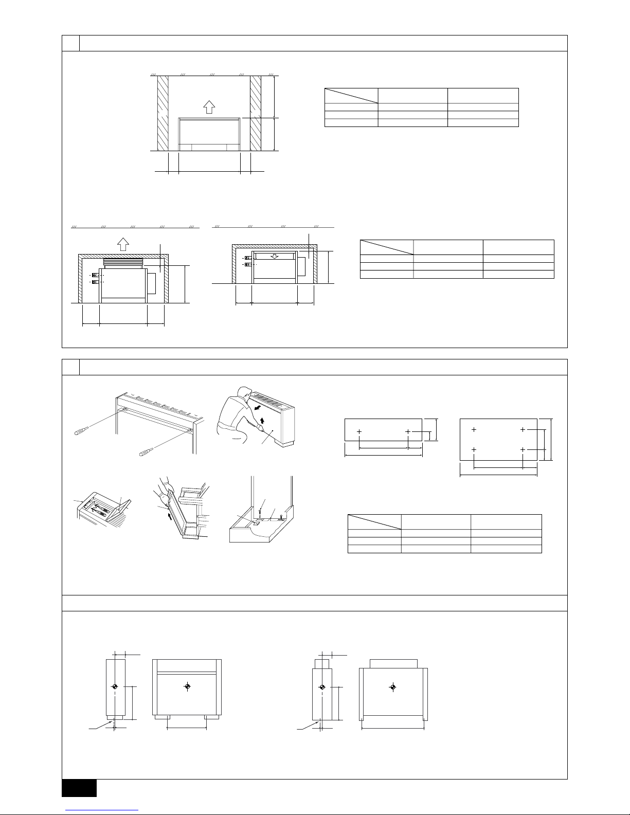
For PFFY-P-VLEM-A (mm)
Model name
(A) (B)
20 · 25 1050 More than 50
32 · 40 1170 More than 50
50 · 63 1410 More than 50
A Floor
B Wall
C Ceiling
D Secure large enough space to prevent that blowout air is blocked.
<Forward blowing type>
For PFFY-P-VLRM-A (mm)
Model name
(C) (D)
20 · 25 660 More than 240
32 · 40 780 More than 240
50 · 63 1030 More than 240
A Floor
B Ceiling
C Piping space
D Electrical part service space
A
C
A
A Front panel B Control panel cover
C Side casing D Floor hole for fixing
E Level adjusting screws (supplied) F Screw plate (supplied)
B
C
D
E
F
A Floor hole for fixing
[Fig. 4.1.6]
220
(F) 205
(E)
114
630
(F) 205
(E)
170 300
For fixing on the floor
<Viewed from bottom of the unit>
For fixing on the wall
<Viewed from front of the unit>
Model name
(E) (F)
20 · 25 1050 640
32 · 40 1170 760
50 · 63 1410 1000
[Fig. 4.2.1]
[Fig. 4.1.2]
[Fig. 4.1.3] [Fig. 4.1.4] [Fig. 4.1.5]
[Fig. 4.1.7]
PFFY-VLEM-E PFFY-VLRM-E
XW
Z
L
A
XW
Z
L
A
3
5
5.1
B
A
C
D
E
A Indoor unit
B Strainer (accessory)
C Drain pan
D Hose band (accessory)
E Drain hose (accessory)
A
B
430 50
90
100 35
F
E
D
C
80
45
G
A
B
430 50
90
100 35
F
E
D
C
80
G
45
A Refrigerant pipe flare connection (for gas): LP
B Refrigerant pipe flare connection (for liquid): HP
C Drain pan
D Stainer
E Hose (accessory) (External diameter ø27 (end ø20))
F Air filter
G Electrical part box
[Fig. 5.1.2]
6
6.2
[Fig. 6.2.1]
1
2
3
2
4
A
B
C
D
8
C
E
9
A Duct
B Tape
C Blowout hole section
D Insulating material
E Insulating material (10 mm in thickness. Be provided around the
blowout hole section.)
[Fig. 4.3.1] [Fig. 4.3.3][Fig. 4.3.2]
4.3
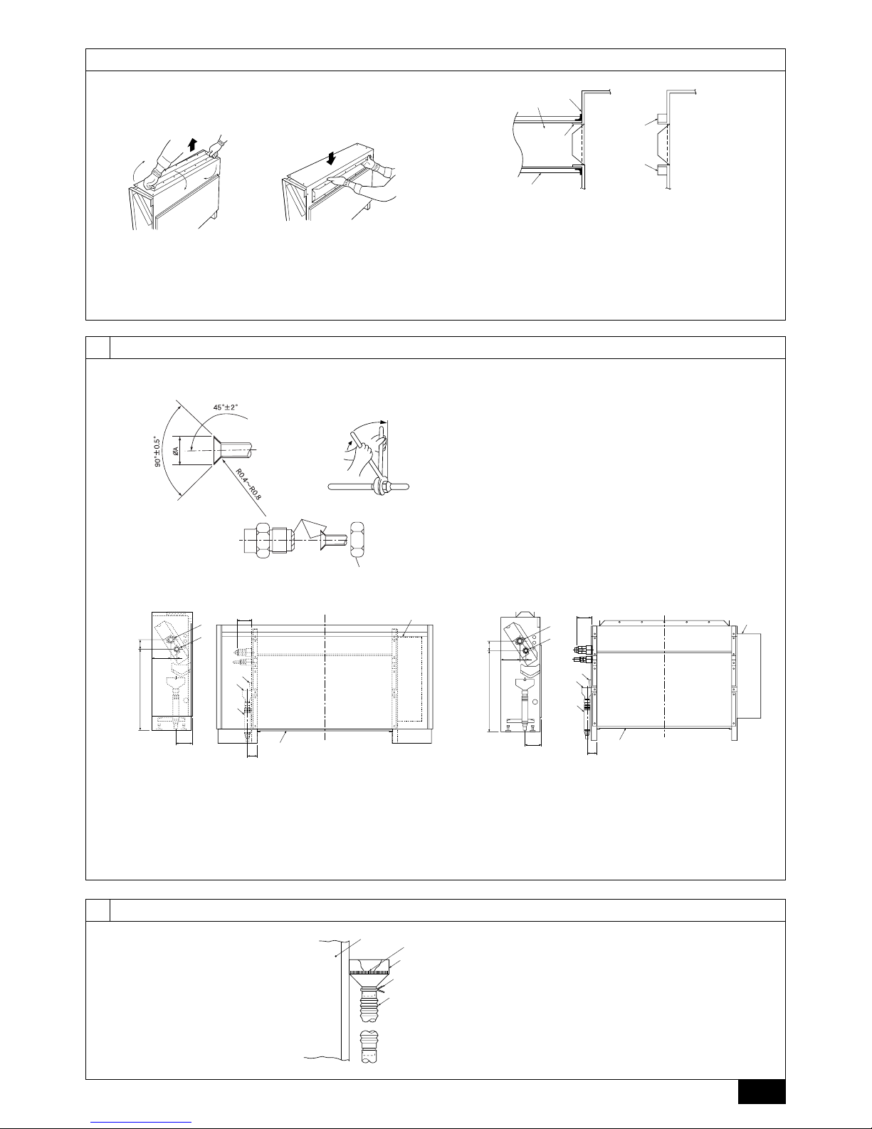
[Fig. 5.1.1]
AB
B
C
A Flare cutting dimensions
B Refrigerant pipe sizes & Flare nut tightening torque
C Apply refrigerating machine oil over the entire flare seat surface.
4
7
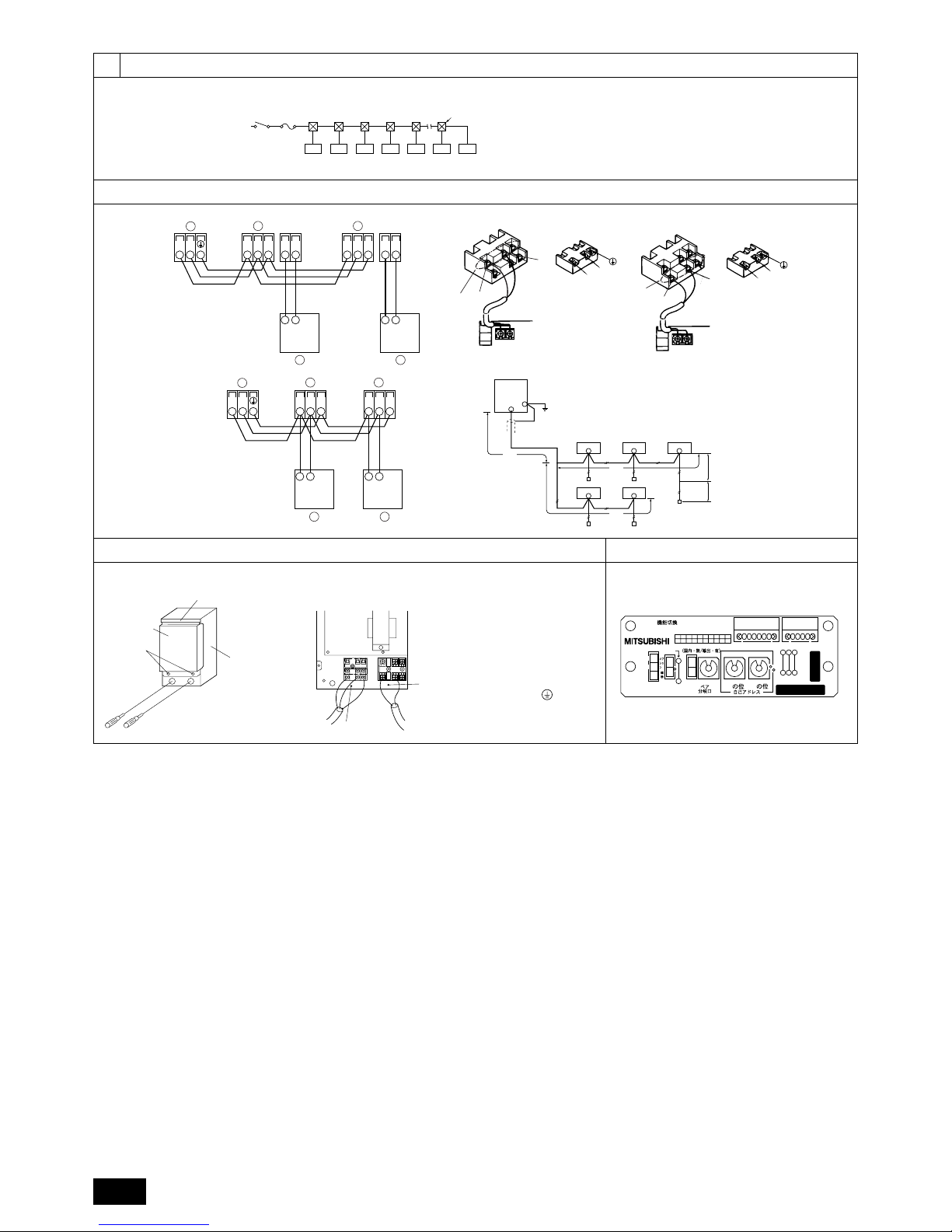
7.1
AB
DE
CCCCCCC
A Switch 16 A
B Overcurrent protection 16 A
C Indoor unit
D Total operating current be less than 16 A
E Pull box
D
A
C
B
1
C
F
E
H
NL
21
CN62
SW1
MADE IN JAPAN
ON
SW14
N0
N0
W254613G03
FP-AD-R
JP2
JP3
JP4
CN828161
10
1
240V 220V
SW5
JP1
SWCSWA
1
3
2
0
SW12
10
0
SW11
1
0
[Fig. 7.1.1]
[Fig. 7.2.1]
A Terminal block for indoor trans-
mission cable
B Terminal block for outdoor
transmission cable
C Remote controller
[Fig. 7.2.2]
M2
DC24~30V
M1
(A, B)
12
D
A
C
L
N
DC10~13V
AB
12
L
N
1
2
A
C
B
A Non-polarized
B Upper level (TB15)
C Remote Controller
D Lower level (TB5)
[Fig. 7.2.3] [Fig. 7.2.4]
7.2
G
III
JJ
JF
II
K
J
H
*1
L1
L2
L4
R
L3
*2
G Outdoor unit
H Earth
I Indoor unit
J Remote controller
K Non-polarized 2-wire
[Fig. 7.2.5]
<Address board>
[Fig. 7.3.1]
[Fig. 7.3.2]
[Fig. 7.4.1]
7.3
A Control box
B Cover
C Screw
D Hook
7.4
A DC 24 to 30 V
B Network remote controller
C Terminal bed for power supply
D Shielding
E Terminal bed for transmission cable
F To single-phase power supply
G To terminal bed for outdoor transmis-
sion cable
* Take shielding earth on the out-
door unit side.
H To terminal bed for transmission cable,
remote controller, indoor BC controller
TB5 TB5
SM1M2 SM1M2
TB3
M1M2
AA
B
CC
TB5 TB15 TB5 TB15
SM1M2 SM1M2
TB3
M1M2 21 21
AA
B
CC
 Loading...