

Mitsubishi Electric City Multi PFD-P250·500VM-E Installation Manual

Air-Conditioners For Building Application
INDOOR UNIT
PFD-P250·500VM-E
INSTALLATION MANUAL
For safe and correct use, please read this installation manual thoroughly before installing the air-conditioner unit.
INSTALLATIONSHANDBUCH
Zum sicheren und ordnungsgemäßen Gebrauch der Klimageräte das Installationshandbuch gründlich durchlesen.
MANUEL D’INSTALLATION
Veuillez lire le manuel d’installation en entier avant d’installer ce climatiseur pour éviter tout accident et vous assurer d’une utilisation correcte.
MANUAL DE INSTALA CIÓN
Para un uso seguro y correcto, lea detalladamente este manual de instalación antes de montar la unidad de aire acondicionado.
MANUALE DI INSTALLAZIONE
Per un uso sicuro e corretto, leggere attentamente questo manuale di installazione prima di installare il condizionatore d’aria.
MANUAL DE INSTALAÇÃO
Para um uso seguro e correcto, é favor ler o manual de instruções por completo antes de utilizar a unidade de ar condicionado.
KURULUM KILAVUZU
Do¤ru ve güvenli kullan›m için, klima ünitesini kullanmadan önce lütfen bu kullanma k›lavuzunu bafltan sona okuyun.
GB
D
F
I
P E
TR
HG
RU
TR
2
5
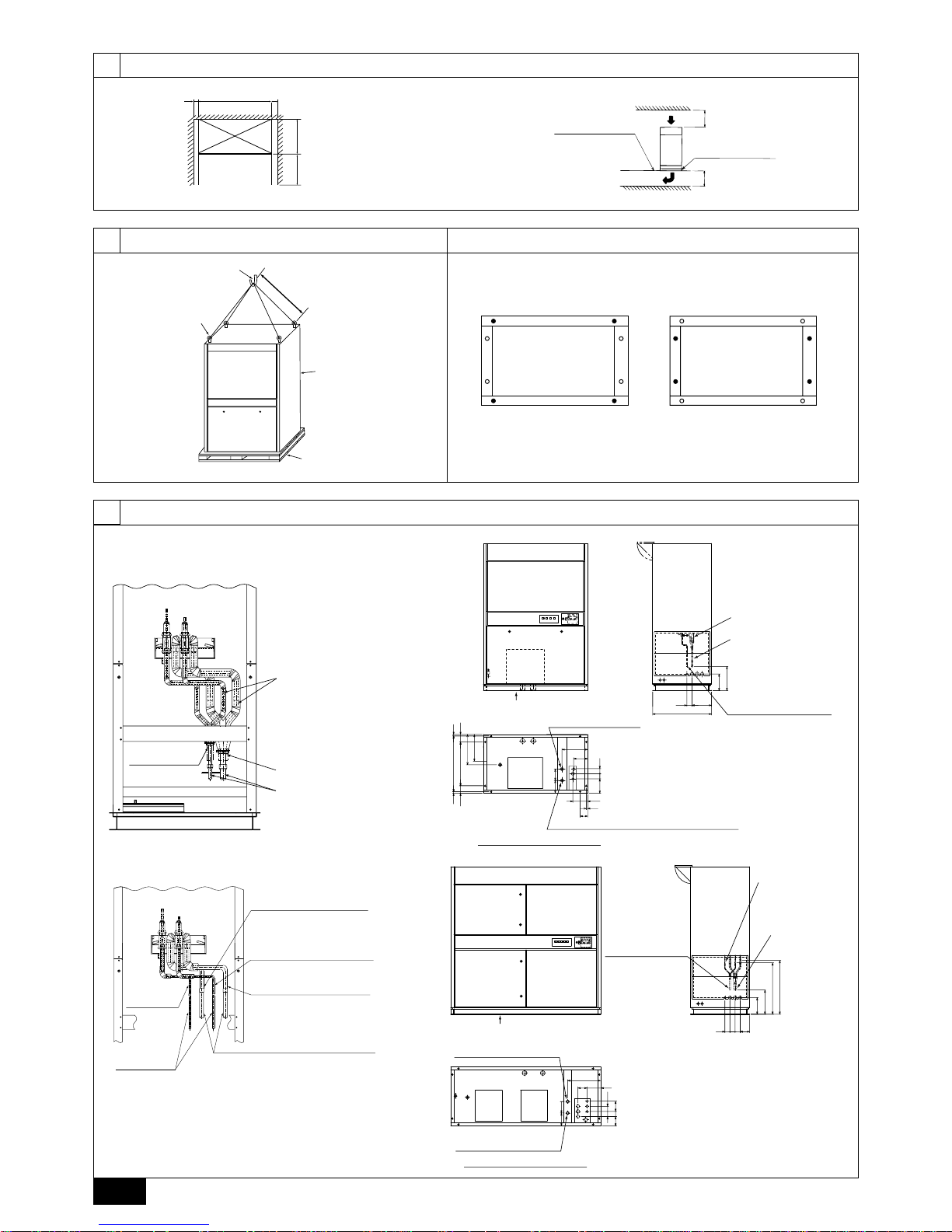
[Fig. 5.1.1]
<A> Single refrigerant circuit
5.1
3
3.1
[Fig. 3.1.1]
[Fig. 4.1.1] [Fig. 4.2.1]
C “•” indicates foundation bolt holes used.
4
4.24.1
[Fig. 3.1.2]
unit
1000
*
mm
>
=
780 mm
ACB
*
300 mm
D Free access floor
E Anti-vibration pad
>
=
300 mm
>
=
A: 200 mm or more
(as seen from top face of unit)
B: 500 mm or more
* It is necessary for the removal of the
panel beyond 600 mm
C: PFD-P250VM-E: 1380 mm
PFD-P500VM-E: 1980 mm
1300 mm
>
=
A Lifting hook
C Unit
D Base
B Eyebolt (supplied)
A Example 1 - Use holes at front and rear. B Example 2 - Use holes at sides.
E Unit weight
PFD-P250VM-E: 380 kg
PFD-P500VM-E: 520 kg
<C> Model 250
<D> Model 500
B
Refrigerant piping
(liquid)
A Thermal insulation
C Refrigerant piping
(gas)
D Piping for close
68 260
320
220
780
186
196
68
68
192
100 580 100
20 740 20
401
365
100
20
150171
340
K Location of
refrigerant piping
L Refrigerant piping
(ø22.2 Brazed) (gas)
M Refrigerant piping
(ø9.52 Brazed) (liquid)
A
N Main drain piping
joint outlet (Rp1-1/4)
W
Air outlet
O Emergency drain piping joint outlet (Rp1-1/4)
P As seen from bottom face A
220
68
68 68
124
320
710
680
135
68
124
120
171 150
440
185
135
<Rp1-1/4>
A
Q Location of
refrigerant piping
R Refrigerant piping
(ø28.58 Brazed)
(gas)
S Refrigerant piping
(ø15.88 Brazed)
(liquid)
W
Air outletWAir outlet
V As seen from bottom face A
U Emergency drain piping
joint outlet (Rp1-1/4)
T Main drain piping joint outlet
(Rp1-1/4)
<B> Two refrigerant circuits
E
No. 1 gas pipe on the unit side
Outer diameter
Model P500:
ø
22.2
H
No. 2 gas pipe on the unit side
Outer diameter
Model 500:
ø
22.2
G
No. 2 liquid pipe on the unit side
Outer diameter:
ø
9.52
F
No. 1 liquid
pipe on the
unit side
J
Field-installed gas pipe
Outer diameter <Expansion work required>
Model 500:
ø
22.2
To be connected to the gas pipe
on the unit pipe by brazing.
* Use non-oxidized brazing material.
I
Field-installed
liquid pipe
Outer diameter:
ø
9.52
<Expansion work required>
To be connected to the liquid pipe
on the unit pipe by brazing.
* Use non-oxidized brazing material.
Outer diameter:
ø
9.52
3
6
6.1
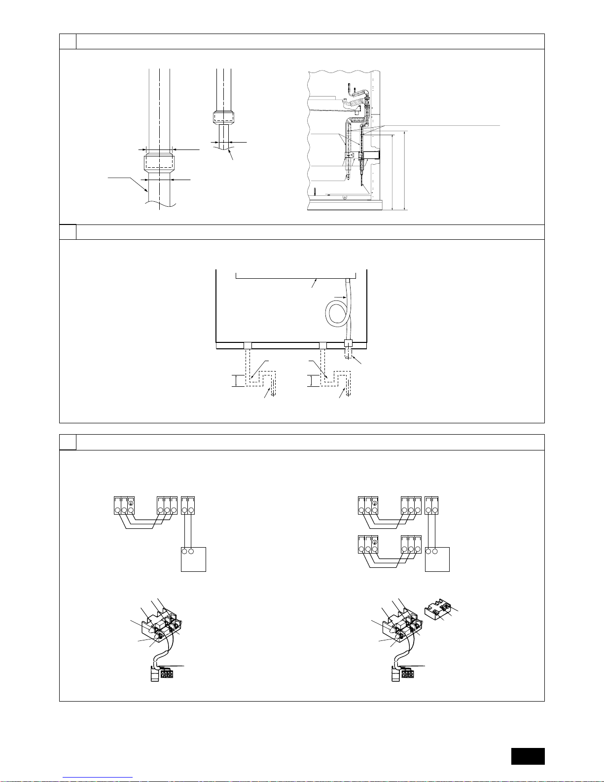
[Fig. 6.1.1]
[Fig. 6.2.1]
[Fig. 7.2.1]
6.2
7
7.2
ø
22.2
(ø28.58) OD
ø
22.2
(ø28.58)
ø9.52
(ø15.88)
A Piping on site
Expand the end of the
pipe and braze it to the
connecting pipe
(non-oxidizing brazing).
B Piping on site
Expand the end of the pipe
and braze it to the connecting
pipe (non-oxidizing brazing).
TB5 TB15
SA1 B1
TB3
M1M2 21
A Terminal block for
indoor transmission
cable
B Terminal block for
outdoor transmission
cable
C MA Remote
controller
TB5-1 TB15
SA1 B1
TB3
M1M2 21
TB5-2
SA2 B2
TB3
M1M2
A Terminal block for
indoor transmission
cable
B Terminal block for
outdoor transmission
cable
C MA Remote
controller
DC10~13V
AB
12
A2
1
2
A Non-polarized
D MA Remote Controller
Upper level
(TB5-1)
C Lower level
(TB15)
B2
S
S
A1
B1
(TB5-2)
DC10~13V
AB
12
A1
1
2
A Non-polarized
D MA Remote Controller
Upper level
(TB5)
C Lower level
(TB15)
B1
S
B B
[Fig. 7.2.2]
<A> Model 250
<A> Model 250
<B> Model 500
<B> Model 500
100mm
or more
100mm
or more
A Drain pan
B Drain hose
C As seen from
front of unit
D Main drain piping
on site
E Emergency drain piping
on site
G Drain piping on site
(for humid filter)
F Trap (on-site
piping work)
A
Pipe cover
B
Pipe
mounting
plate
C
Refrigerant
piping (gas)
D
Refrigerant
piping (liquid)
680 (Cut the liquid pipe here)
710 (Cut the gas pipe here)
When the unit is connected to a 2-refrigerant circuit,
cut off these pipes approximately 20 mm above
the point where expanded pipes are connected.
<Preparation of the pipes in a 2-refrigerant-circuit>
• Remove the pipe mounting plate.
• Peel off the pipe cover.
• Cut off both pipes at the specified location.
[Fig. 6.1.2]
6
4
7
7.3
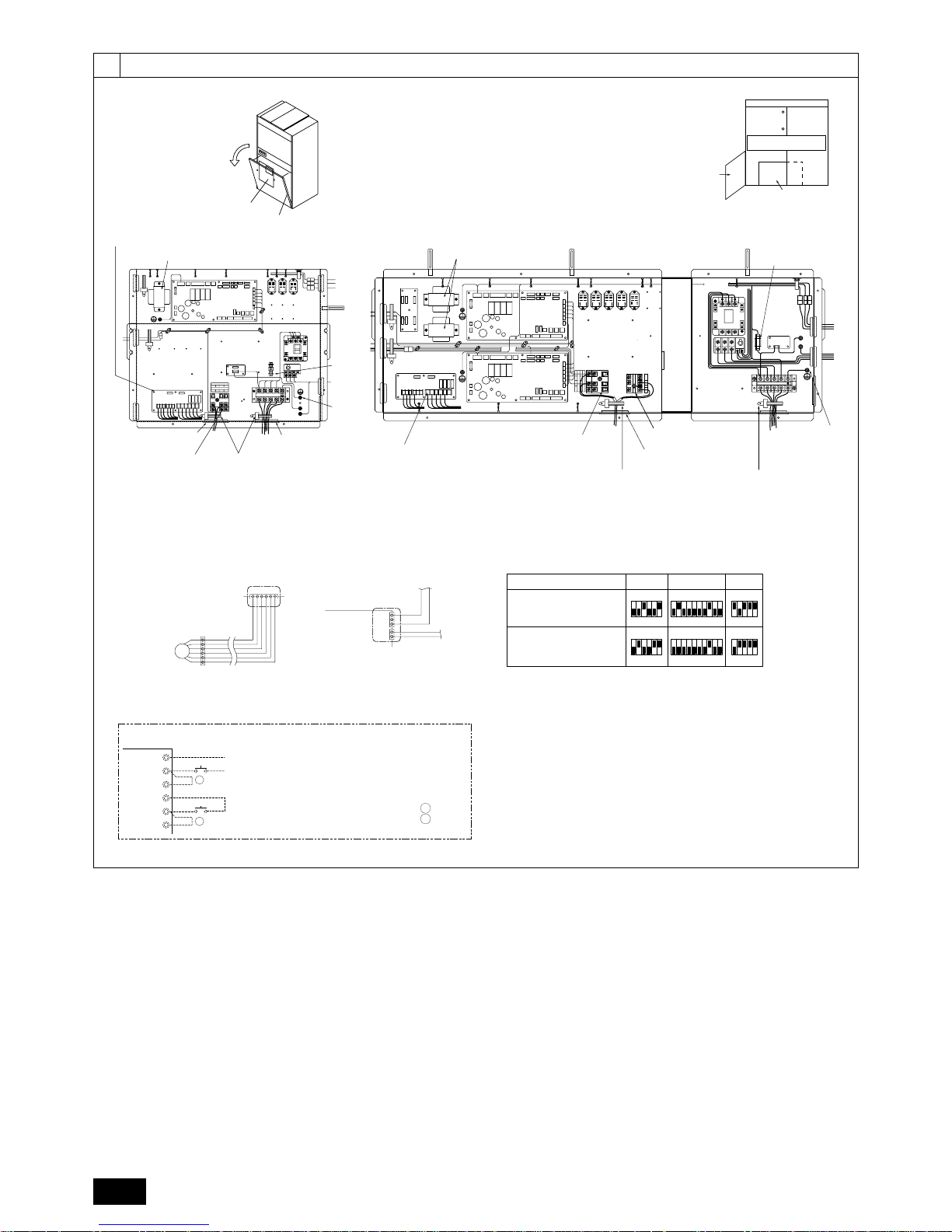
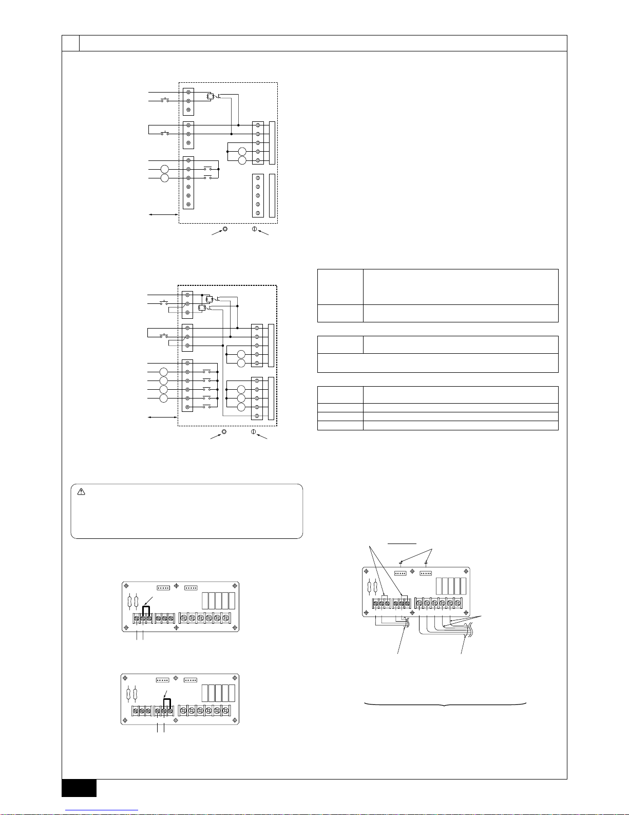
[Fig. 7.3.1]
A Transformer
A Transformer
E Connect trasmission
line to outdoor unit
D Fix in place after
connecting writing.
F To power supply
B External I/O board
H Fuse
G Earth
D No.2 Transmission line
terminal block
(Note: Connect to top
terminal block)
C No.1 Transmission line
terminal block
E Connect trasmission line
to outdoor unit
F Fix in place after connecting writing.
G Earth
B External I/O board
C Transmission line
terminal block
H Fuse
I Control box
J Bottom panel
I Control Box
J Bottom panel
<A> Model 250 <B> Model 500
[Fig. 7.3.2]
Connection changes to be made when connected to a 2-refrigerant circuit
When connected to
a 2-refrigerant circuit
When connected to
a 2-refrigerant circuit
Remove the LEV2B connector
from the adapter board, and
connect it to CN60 on No. 2 board.
CN60
6 5 4 3 2 1
6
5
4
3
2
1
CN3A
CN2M
1
2
2
1
3
No. 2 board
Connect the connectors to
CN3A and CN2M on No. 2 board.
When connected to a
single-refrigerant circuit
(factory setting)
When connected to t a
2-refrigerant circuit
Model 500 SW2 SW3 SW4
ON
123456 12345123456789
10
123456 12345123456789
10
ON ON
ON ON ON
LEV2
Switch setting changes to be made when connected to a 2-refrigerant circuit.
External input-output
board (IFB)
AC
A1
A2
BC
B1
B2
The case of with-voltage input
...
A
The case of no-voltage input
....
B
A
B
TB23
TB21
When using the external input function on the
indoor unit that is connected to a two-refrigerant
circuit, connect the short-circuit plate that is
supplied with the unit to the appropriate terminals
on the external input-output board.
5
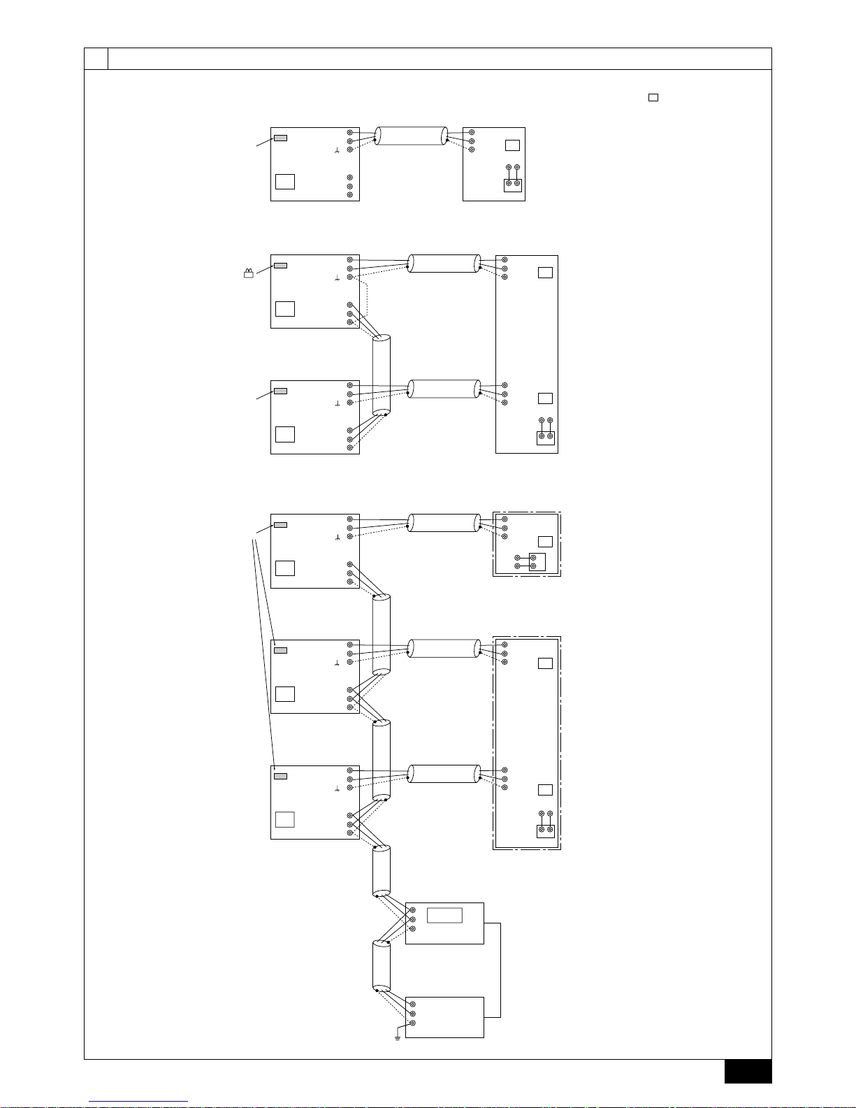
7.4
[Fig. 7.4.1]
[Fig. 7.4.2]
[Fig. 7.4.3]
• When there is a single Model 250 unit
• When there is a single Model 500 unit (Two refrigerant circuits)
• When connected to G50
TB3
TB7
M1
M2
M1
M2
S
M1
TB5
TB15
MA
12
M2
AB
S
51
<PUHY-P250YGM-A>
G-50
000
D Power supply unit
IC
CN41
01
TB3
TB7
M1
M2
M1
M2
S
M1
TB5-1
TB5-2
M2
S
51
OC <PUHY-P250YGM-A> IC
01
TB3
TB7
M1
M2
M1
M2
S
M1
TB15
MA
12
M2
AB
S
52
OC <PUHY-P250YGM-A>
02
TB15
MA
12
AB
TB3
TB7
M1
M2
M1
M2
S
M1
TB5
TB5-1
TB5-2
M2
S
51
OC
IC
(model 250)
IC (model 500)
01
TB3
TB7
M1
M2
M1
M2
S
M1
TB15
MA
1
2
M2
A
B
S
53
OC
03
04
M1
M2
S
TB3
TB7
M1
M2
M1
M2
S
54
OC
OC
A
B
S
A
B
S
TB2
*2 The Model 250 indoor unit
contains one indoor controller board.
A CN41 as it is
A
Replace CN41
with CN40
B Group 1
C Group 2
A CN41 as it is
B CN41 as it is
*1 The numbers shown
in the square ( )are addresses.
* The Model 500 indoor unit
contains two indoor controller boards.
E DC Power supply (DC 12V)
7
6
7.5
B External power supply
C Start/Stop
E Common
F Start/Stop
H Display power supply
A With-voltage input
K External I/O board
D No-voltage input
G Relay contact output
I Operation status
J Fault
L Terminal block connection
M Connector connection
N Wiring distance 100 m or less.
L1
L2
SW12
SW11
CN53
1
2
3
4
5
1
2
3
4
5
TB21
TB22
TB23
XA
XB
XB
XA
COM
1
2
BC
B1
B2
AC
A1
A2
3
4
5
CN54
[Fig. 7.5.1]
[Fig. 7.5.2]
Display
power supply
L1, L3
L2, L4
XA ~ XE
DC30 V 1 A or less
AC220 - 240 V 1 A
Operation status
Fault status
Relay (allowable current 10mA - 1 A)
G Relay contact output
<A> Model 250
<B> Model 500
B External power supply
C Start/Stop
A With-voltage input
E Common
F Start/Stop
H Display power supply
D No-voltage input
G Relay contact output
I Operation status (No.1)
J Fault (No.1)
I Operation status (No.2)
J Fault (No.2)
L Terminal block connection
M Connector connection
N Wiring distance 100 m or less.
SW12
K External I/O board
L1
L2
L3
L4
(*1)
Short circuit plate
(*1)
Short circuit plate
SW11
CN53
1
2
3
4
5
1
2
3
4
5
TB21
TB22
TB23
XA
XB
XC
XE
XD
XE
XD
XC
XB
XA
COM
1
2
BC
B1
B2
AC
A1
A2
3
4
5
CN54
7
• Notes on using external functions (Model 500 only)
(*1)
For instructions on how to install the short circuit plate, refer to “Notes on using
external input function” shown below.
When using the external input function on the indoor unit that is connected to a tworefrigerant circuit, connect the short-circuit plate that is supplied with the unit to the
appropriate terminals on the external input-output board.
Without the short-circuit plate, the unit will not function properly.
Don’t connect the short-circuit plate in case of a one-refrigerant circuit.
Caution
External input-output board
<The case of with-voltage input>
· Connecting the short-circuit plate
<The case of no-voltage input>
External input-output board
Short-circuit plate
External input
54321COM
B2B1BCA2A1AC
TB23
TB21 TB22
CN53 CN54
Short-circuit plate
External input
54321COM
TB23
TB21 TB22
CN53 CN54
B2A2A1AC B1BC
A Site wiring
B Fix low-voltage system
(DC30 V or less) wiring
with clamps and pass to
unit via transmission line
wiring holes.*1
C Fix high-voltage system
(AC220 - 240 V) wiring
with clamps and pass to
unit via power supply
wiring holes.*2
D To CN51 on control board
(inner wiring)
E model 500 only
E model 500 only
For instructions on how to install
the short circuit plate, refer to
"Notes on using external input
function" shown on the left.
54321COM
B2B1BCA2A1AC
TB23
TB21 TB22
CN53 CN54
SW11
Remote Start/Stop switch
* Toggles ON/OFF each time switch is pressed (pulse input).
Contact:Minimum applicable load DC 12 V 1 mA
Contact rating DC 12 V 0.1 A and over
D No-voltage input
A With-voltage input
External
power supply
SW12
Pulse input of start or stop
DC12 - 24 V
Input current (per contact)
Approximately 10 mA (DC12 V)
Remote Start/Stop switch
* Toggles ON/OFF each time switch is pressed (pulse input).
 Loading...