

Mitsubishi Electric CITY MULTI PFD-P250-A, CITY MULTI PFD-500VM-A Installation Manual

Air-Conditioners For Building Application
INDOOR UNIT
PFD-P250·500VM-A
INSTALLATION MANUAL
For safe and correct use, please read this installation manual thoroughly before installing the air-conditioner unit.
INSTALLATIONSHANDBUCH
Zum sicheren und ordnungsgemäßen Gebrauch der Klimageräte das Installationshandbuch gründlich durchlesen.
MANUEL D’INSTALLATION
Veuillez lire le manuel d’installation en entier avant d’installer ce climatiseur pour éviter tout accident et vous assurer d’une utilisation correcte.
MANUAL DE INSTALACIÓN
Para un uso seguro y correcto, lea detalladamente este manual de instalación antes de montar la unidad de aire acondicionado.
MANUALE DI INSTALLAZIONE
Per un uso sicuro e corretto, leggere attentamente questo manuale di installazione prima di installare il condizionatore d’aria.
INSTALLATIEHANDLEIDING
Voor een veilig en juist gebruik moet u deze installatiehandleiding grondig doorlezen voordat u de airconditioner installeert.
РУКОВОДСТВО ПО УСТАНОВКЕ
Для осторожного и правильного использования прибора необходимо тщательно ознакомиться с данным руководством по
установке до выполнения установки кондиционера.
GB
D
F
I
NL
E
RU
GR
RU
TR
2
5
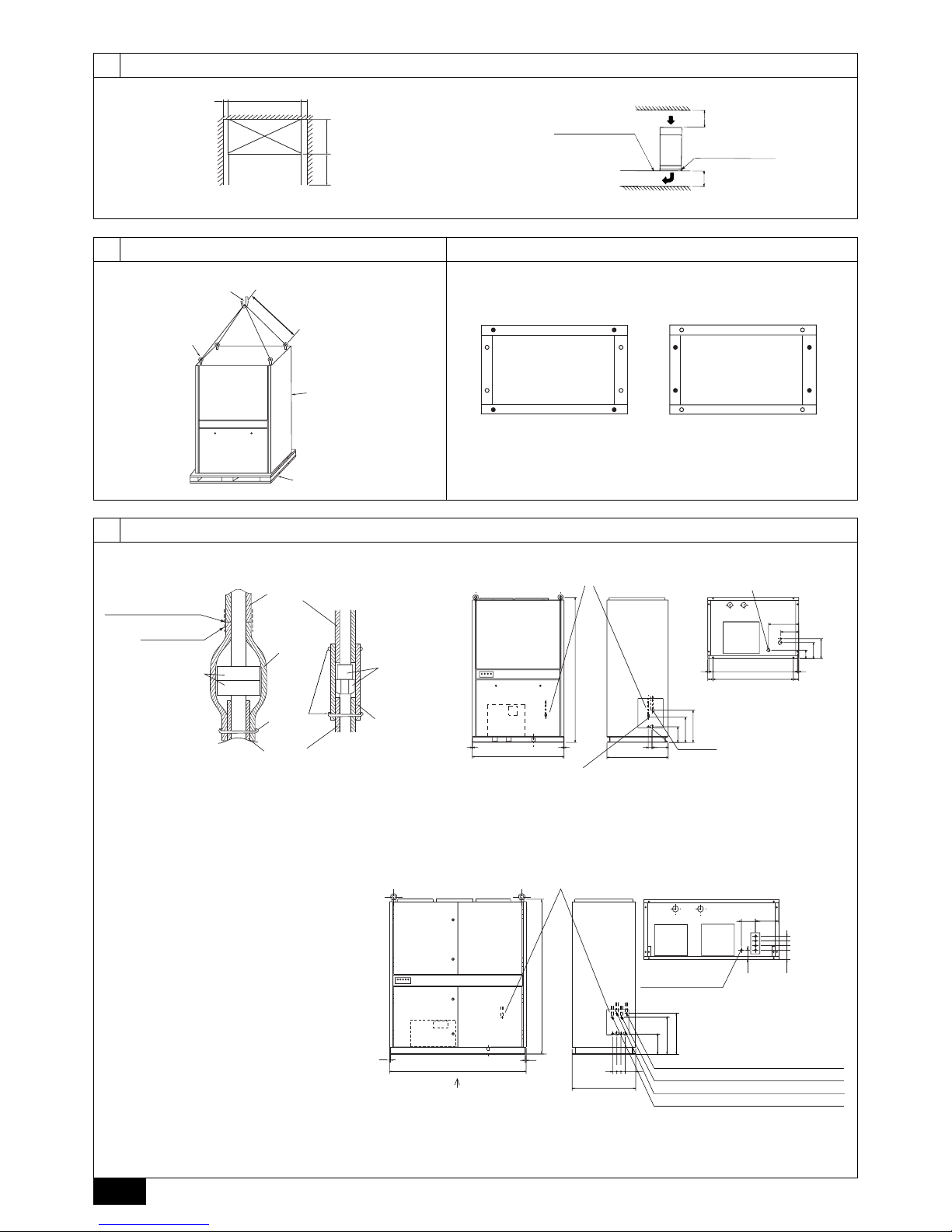
[Fig. 5.1.1]
5.1
3
3.1
[Fig. 3.1.1]
[Fig. 4.1.1] [Fig. 4.2.1]
C “•” indicates foundation bolt holes used.
4
4.24.1
[Fig. 3.1.2]
1200 mm
unit
800 mm
>
=
800 mm
AA
*
300 mm
B Free access floor
C Anti-vibration pad
>
=
300 mm
>
=
A: 200 mm or more (as seen from top face of unit)
* At least 500 mm when piping is taken from the right side.
1300 mm
>
=
A Lifting hook
C Unit
D Base
B Eyebolt (supplied)
A Example 1 - Use holes at front and rear. B Example 2 - Use holes at sides.
B Sealing tape
C Flange
H Flare
A Joint (Ensure that there
is no gap in the joint.)
E Flange cover
(supplied)
D Thermal insulating
material inside unit
I Thermal insulating
material (procured
on-site)
G Site thermal
insulating material
F Bind with
band or tape
235
210
260
340
420
205
210
50
395
110
15 151160
70
1050
70
1895
800
5
5
1200
1A
K
Refrigerant piping flange (gas)
O
Air outlet
M
Drain piping joint outlet (Rp1)
N
As seen from bottom face A.
L
Refrigerant piping flare (ø12.7) (liquid)
J
Location of refrigerant piping
<A> Gas <B> Liquid
E Unit weight
PFD-P250VM-A: 350 kg
PFD-P500VM-A: 500 kg
<C> Model 250
1800
1895
5
5
250
150
110
A
50
50
50
100
110
50
50
205
340
420
800
O
Air outletOAir outlet
N
As seen from bottom face A.
K
Refrigerant piping flange (gas)
L
Refrigerant piping flare (ø12.7) (liquid)
K
Refrigerant piping flange (gas) No. 2
No. 2
No. 1
No. 1
L
Refrigerant piping flare (ø12.7) (liquid)
J
Location of refrigerant piping
50
M
Drain piping joint
outlet (Rp1)
<D> Model 500
3
6
6.1
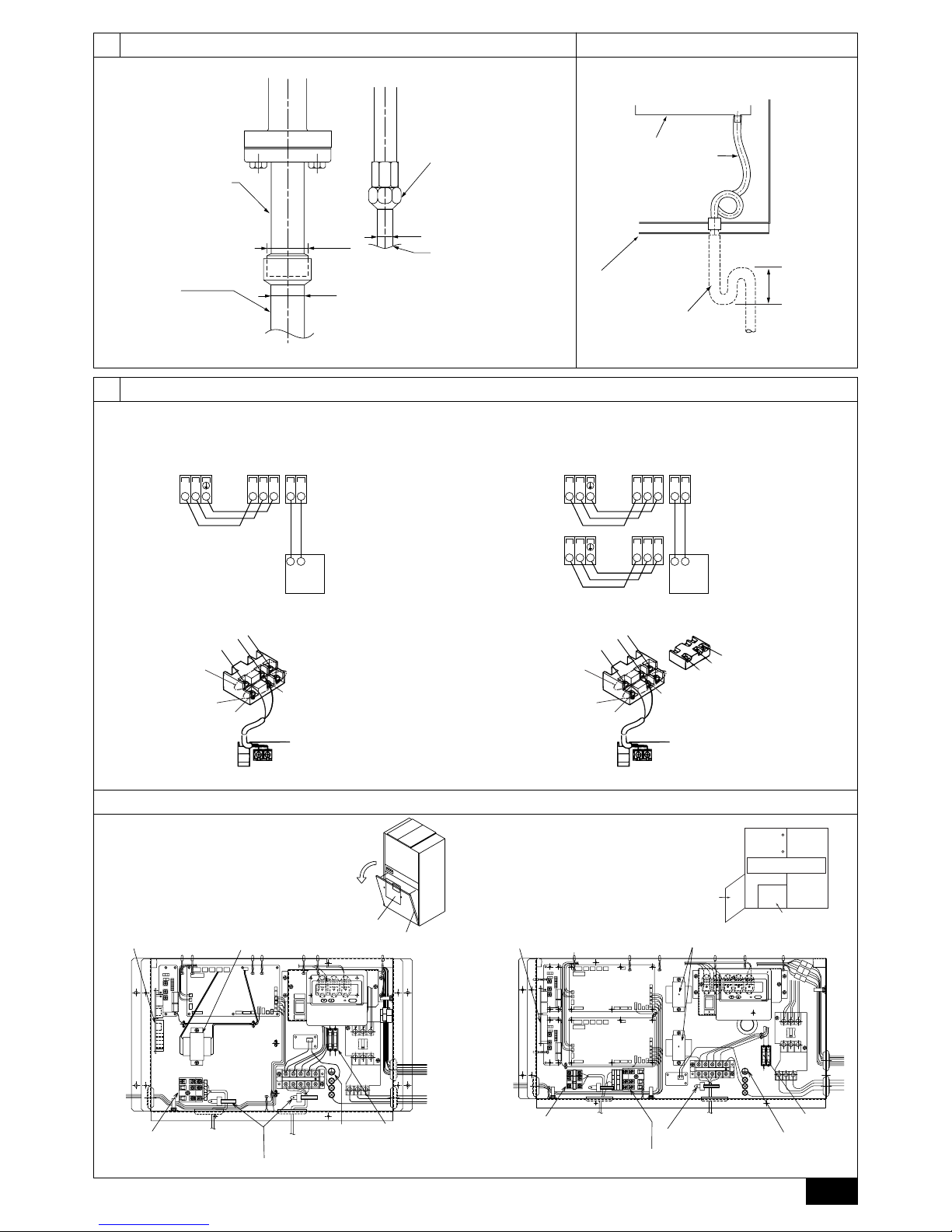
[Fig. 6.1.1] [Fig. 6.2.1]
[Fig. 7.2.1]
6.2
7
7.2
ø28.58 OD
ø28.58
ø12.7
A Connecting pipe (supplied)
Fit packing (supplied) firmly
(50 N·m torque) to the
flange to prevent a gas leak.
Apply refrigerator oil (ester
oil, ether oil, or a small
amount of alkyl benzene) to
both sides of the packing.
B Piping on site
Expand the end of the
pipe and braze it to the
connecting pipe (nonoxidizing brazing).
C Flared nut
Tighten to 55 N·m torque.
Open and close with a double
spanner.
Apply refrigerator oil (ester oil,
ether oil, or a small amount of
alkyl benzene) to the contact
surfaces of the flare.
D Piping on site
Expand the end of the pipe
and connect it. Do not use the
supplied piping.
A Drain pan
B Drain hose
C Trap
(on-site piping
work)
F 200 mm or more
D Unit base
(main drain pan)
E As seen from
front of unit.
TB5 TB15
SA1 B1
TB3
M1M2 21
A Terminal block for
indoor transmission
cable
B Terminal block for
outdoor transmission
cable
C MA Remote
controller
TB5-1 TB15
SA1 B1
TB3
M1M2 21
TB5-2
SA2 B2
TB3
M1M2
A Terminal block for
indoor transmission
cable
B Terminal block for
outdoor transmission
cable
C MA Remote
controller
DC10~13V
AB
12
A2
1
2
A Non-polarized
D MA Remote Controller
Upper level
(TB5-1)
C Lower level
(TB15)
B2
S
S
A1
B1
(TB5-2)
DC10~13V
AB
12
A1
1
2
A Non-polarized
D MA Remote Controller
Upper level
(TB5)
C Lower level
(TB15)
B1
S
B B
[Fig. 7.2.2]
7.3
[Fig. 7.3.1]
NO.2
NO.1
local
nomal
CN2M
CN29
CN21
CN20
CN3A
CN31
CN25
CN60
CN81
CN42
CN24
CN70
CNT
CND
CN3T
CN23
CNV
CN2M
CN29
CN21
CN20
CN3A
CN31
CN25
CN60
CN81
CN42
CN24
CN70
CNT
CND
CN3T
CN23
CNV
1A
5A
DOWN(Remote Controller)
UP(Transmission Line)
SB1A1
A2 B2
12
S
N
L3
L2
L1
normal
local
CNV
CN23
CN3T
CND
CNT
CN70
CN24
CN42
CN81
CN60
CN25 CN31
CN3A
CN20
CN21
CN29
CN2M
5A1A
L1
L2
L3
N
432
1
A Transformer
B External I/O board
G Earth
H Fuse
C No.1 transmission
line terminal block
C No.2 transmission line terminal block
(Note: Connect to top terminal block)
D Fix in place after
connecting wiring.
E Connect
transmission line
to outdoor unit
F To power supply
E Connect
transmission line
to outdoor unit
F To power supply
A Transformer
B External I/O board
G Earth
H Fuse
C Transmission
line terminal
block
D Fix in place after connecting wiring.
I Control box
J Bottom panel
<A> Model 250
<A> Model 250
<B> Model 500
<B> Model 500
I Control Box
J Bottom panel
<A> Model 250 <B> Model 500
4
7.4
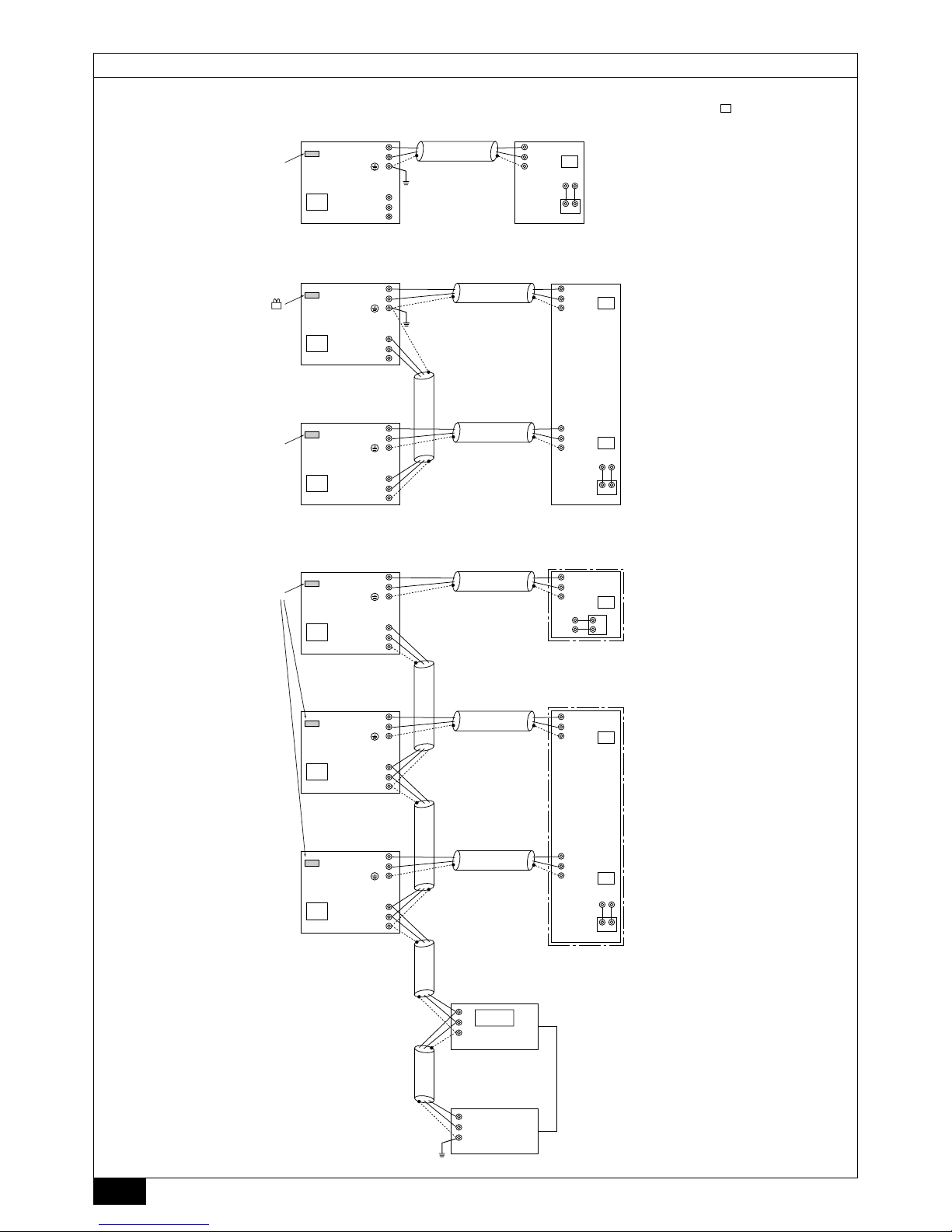
[Fig. 7.4.1]
[Fig. 7.4.2]
[Fig. 7.4.3]
• When there is a single Model 250 unit
• When there is a single Model 500 unit
• When connected to G50
TB3
TB7
M1
M2
M1
M2
S
M1
TB5
TB15
MA
12
M2
A1 B2
S
51
<PUD-P250YMF-C>
G-50
000
D Power supply unit
IC
CN41
01
TB3
TB7
M1
M2
M1
M2
S
M1
TB5-1
TB5-2
M2
S
51
OC <PUD-P250YMF-C> IC
01
TB3
TB7
M1
M2
M1
M2
S
M1
TB15
MA
12
M2
A1 B2
S
52
OC <PUD-P250YMF-C>
02
TB15
MA
12
A1 B2
TB3
TB7
M1
M2
M1
M2
S
M1
TB5
TB5-1
TB5-2
M2
S
51
OC
IC
(model 250)
IC (model 500)
01
TB3
TB7
M1
M2
M1
M2
S
M1
TB15
MA
1
2
M2
A1
B2
S
53
OC
03
04
M1
M2
S
TB3
TB7
M1
M2
M1
M2
S
54
OC
OC
A
B
S
A
B
S
TB2
*2 The Model 250 indoor unit
contains one indoor controller board.
A CN41 as it is
A
Replace CN41
with CN40
B Group 1
C Group 2
A CN41 as it is
B CN41 as it is
*1 The numbers shown
in the square ( )are addresses.
* The Model 500 indoor unit
contains two indoor controller boards.
E DC Power supply (DC 12V)
 Loading...