

Mitsubishi Electric City Multi PEFY-WP20, City Multi PEFY-WP40, City Multi PEFY-WP25, City Multi PEFY-WP32, City Multi PEFY-WP50VMA-E Installation Manual

Air-Conditioners
INDOOR UNIT
PEFY-WP20, 25, 32, 40, 50VMA-E
GB
INSTALLATION MANUAL
For safe and correct use, please read this installation manual thoroughly before installing the air-conditioner unit.
2
33.2
[Fig. 3.2.1]
44.1
[Fig. 4.1.1]
55.1 5.2
[Fig. 5.1.1] [Fig. 5.1.2] [Fig. 5.2.1]
66.2
[Fig. 6.2.1]
B
C
D
A
F
G
3
4
E
A
50~150 450
450
49
643
777
20
64
23
C
B
A
D
B
E
250
1
2
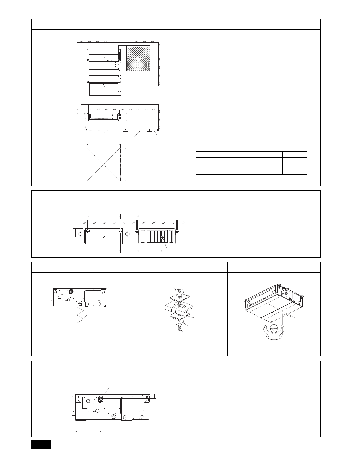
A Access door
B Electrical parts box 1 600 mm or more
C Air inlet 2 100 mm or more
D Air outlet 3 20 mm or more
E Ceiling surface 4 300 mm or more
F Service space (viewed from the side)
G Service space (viewed from the direction of arrow)
(mm)
Model A B C D E
PEFY-WP20VMA-E 700 754 800 660 800
PEFY-WP25, 32VMA-E 900 954 1000 860 1000
PEFY-WP40, 50VMA-E 1100 1154 1200 1060 1200
YX
LW
A
Z
A Center of gravity
B
A
A Unit body
B Lifting machine
C
D
C
E
D
C Nuts (field supply)
D Washers (field supply)
E M10 hanging bolt (field supply)
A
A Indoor unit’s bottom surface
A
239
41
A Drain pipe (O.D. ø32)
3
6.3
[Fig. 6.3.1]
[Fig. 6.3.2]
6.4
[Fig. 6.4.1] [Fig. 6.4.2]
77.2
C
B
A
L
D
D
D
E
K
M
B
H
I
Max. 20m
1.5-2m
G
F
FF
B
J
O
N
F
Max. 300mm
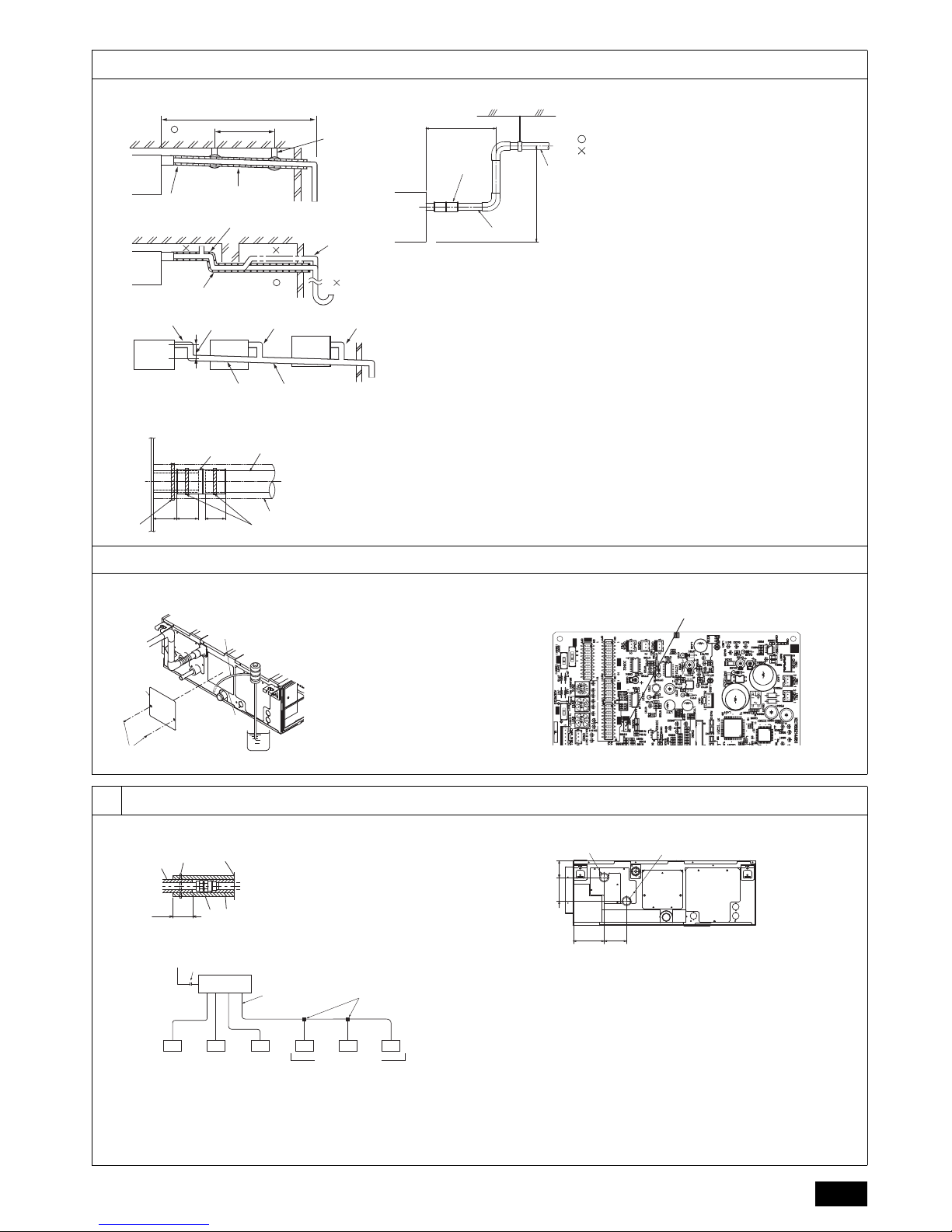
Grouped piping
Correct piping
Wrong piping
A Insulation (9 mm or more)
B Downward slope (1/100 or more)
C Support metal
K Air bleeder
L Raised
M Odor trap
D O. D. ø32 PVC TUBE
E Make it as large as possible. About 10 cm.
F Indoor unit
G Make the piping size large for grouped piping.
H Downward slope (1/100 or more)
I O. D. ø38 PVC TUBE for grouped piping.
(9 mm or more insulation)
J Up to 550 mm
N Drain hose (accessory)
O Horizontal or slightly upgradient
B
CD D
G
F
E
H
A
3235 25
A Indoor unit
B Tie band (accessory)
C Visible part
D Insertion margin
E Drain hose (accessory)
F Drain pipe (O.D. ø32 PVC TUBE, field supply)
G Insulating material (field supply)
H Tie band (accessory)
A
B
F
C
D
E
A Insert pump’s end 2 to 4 cm.
B Remove the water supply port.
C About 2500 cc
D Water
E Filling port
F Screw
SWE
<Indoor controller board>
F
E
D
C
B
A
D
DD
DDFD
A
B
E
*1
C
A
B
117 87
64
91
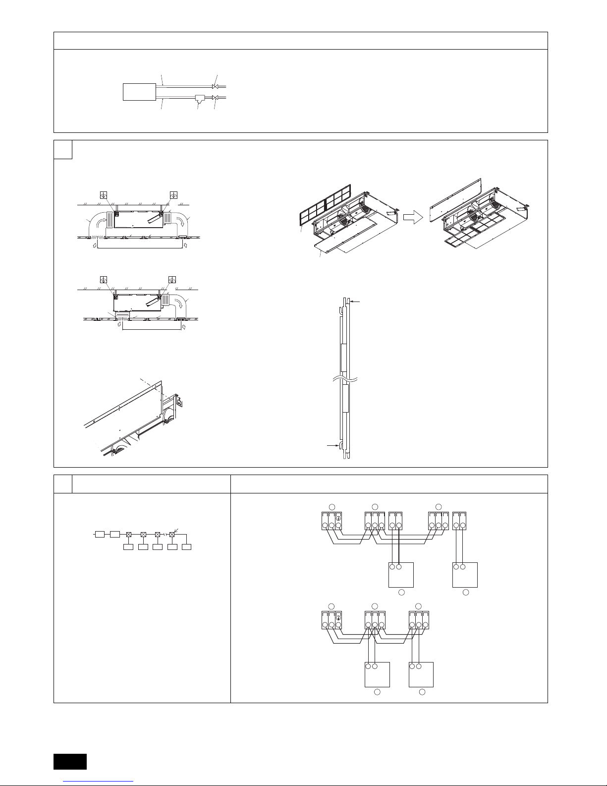
A Locally procured insulating material
for pipes
B Bind here using band or tape.
C Do not leave any opening.
D Lap margin: more than 40 mm
E Insulating material (field supply)
F Unit side insulating material
A To outdoor unit
B End connection (brazing)
C HBC controller
D Indoor unit
E Twinning pipe (field supply)
F Up to three units for 1 branch hole ; total capacity: below 80 (but in same mode,
cooling/heating)
Water pipework is screw
connections
Note:
*1. Connection of multiple indoor units with one connection (or joint pipe)
• Total capacity of connectable indoor units: Less than 80
• Number of connectable indoor units: Maximum 3 Sets
• Selection of water piping
Select the size according to the total capacity of indoor units to be installed
downstream.
• Please group units that operate on 1 branch.
[Fig. 7.2.3]
[Fig. 7.2.1] [Fig. 7.2.2]
A Water pipe: To HBC unit
B Water pipe: From HBC unit
4
7.2
[Fig. 7.2.4]
8
[Fig. 8.0.1]
[Fig. 8.0.3]
[Fig. 8.0.2]
[Fig. 8.0.4]
99.1 9.2
[Fig. 9.1.1]
C
B ED
E
A
A Indoor unit
B Water pipe: From HBC unit
C Water pipe: To HBC unit
D Strainer (40 mesh or more)
(field supply)
E Shut off valve
(field supply)
A
B
G
F
A
CE
D
A Duct
B Air inlet
C Access door
D Canvas duct
E Ceiling surface
F Air outlet
G Leave distance
enough to prevent
short cycle
<A> In case of rear inlet
A
B
G
C
E
A
F
D
<B> In case of bottom inlet
A
B
A Filter
B Bottom plate
C
D
C Nail for the bottom inlet
D Nail for the rear inlet
AB
CCCCDC
~220V
A Ground-fault interrupter
B Local switch/Wiring breaker
C Indoor unit
D Pull box
TB5 TB15 TB5 TB15
SM1M2 SM1M2
TB3
M1M2 21 21
AA
B
CC
[Fig. 9.2.1]
TB5 TB5
SM1M2 SM1M2
TB3
M1M2
AA
B
CC
[Fig. 9.2.2]
A Terminal block for indoor
transmission cable
B Terminal block for outdoor
transmission cable
C Remote controller
5
9.2
[Fig. 9.2.3] [Fig. 9.2.4]
9.3
9.5
[Fig. 9.5.1]
2
S
M2
M1
A
B
D
1
DC10~13V
AB
12
L
N
C
D
A
S
M2
M1
B
1
2
L
N
DC24~30V
(A, B)
12
C
A Non-polarized
B TB15
C Remote Controller
D TB5
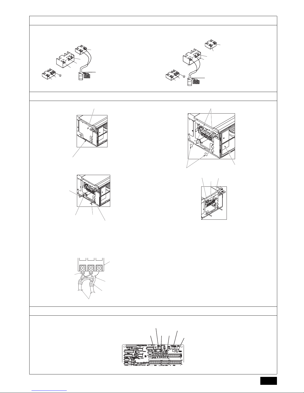
A
B
A Screw holding cover (1pc)
B Cover
[Fig. 9.3.1]
H
I
F
G
F Use PG bushing to keep the weight of the cable and external force from being
applied to the power supply terminal connector. Use a cable tie to secure the
cable.
G Power source wiring
H Use ordinary bushing
I Transmission wiring
[Fig. 9.3.3]
C
D
E
C Ter mi n a l b ox
D Knockout hole
E Remove
[Fig. 9.3.2]
J
L
K
J Terminal block for power source
K Terminal block for indoor transmission
L Terminal block for remote controller
[Fig. 9.3.4]
M2 SM1
A
B
C
E
D
A Ter mi nal bl o c k
B Round terminal
C Shield wire
D The earth wire from two cables are connected together to the S terminal. (Dead-end connection)
E Insulation tape (To keep the earth wire of the shielded cable from coming in contact with the transmission
terminal)
[Fig. 9.3.5]
<Indoor controller board>
SWC
SW11 SW12 SW14
SW5
SWA
 Loading...