

Mitsubishi Electric City Multi PEFY-P30NMHU-E-F, City Multi PEFY-P54NMHU-E-F, City Multi PEFY-P72NMHU-E-F, City Multi PEFY-P96NMHU-E-F Service Manual
TECHNICAL & SERVICE MANUAL
Multiple Split type Air-Conditioners
<Indoor unit>
Models
Ceiling Concealed (Fresh Air Intake type)
Series PEFY
PEFY-P30NMHU-E-F
PEFY-P54NMHU-E-F
PEFY-P72NMHU-E-F
PEFY-P96NMHU-E-F
INDOOR UNIT
CONTENTS
SAFETY PRECAUTIONS ·························1
1. FEATURES ···········································3
2. PART NAMES AND FUNCTIONS········4
3. SPECIFICATION ···································6
4. OUTLINES AND DIMENSIONS············8
5. WIRING DIAGRAM ·····························10
6.
REFRIGERANT SYSTEM DIAGRAM
12····
7. TROUBLE SHOOTING ·······················13
8. DISASSEMBLY PROCEDURE ···········
16
For use with the R410A & R22
2005
1
SAFETY PRECAUTIONS
and install the unit at the specified place.
- Improper installation may cause the unit to topple and result in
injury.
• Always use an air cleaner, humidifier, electric heater, and other
accessories specified by Mitsubishi Electric.
- Ask an authorized technician to install the accessories. Improper
installation by the user may result in water leakage, electric shock,
or fire.
• Never repair the unit. If the air conditioner must be repaired,
consult the dealer.
- If the unit is repaired improperly, water leakage, electric shock, or
fire may result.
• Do not touch the heat exchanger fins.
- Improper handling may result in injury.
• If refrigerant gas leaks during installation work, ventilate the
room.
- If the refrigerant gas comes into contact with a flame, poisonous
gases will be released.
• Install the air conditioner according to this Installation Manual.
- If the unit is installed improperly, water leakage, electric shock, or
fire may result.
• Have all electric work done by a licensed electrician according
to “Electric Facility Engineering Standard” and “Interior Wire
Regulations”and the instructions given in this manual and always use a special circuit.
- If the power source capacity is inadequate or electric work is per-
formed improperly, electric shock and fire may result.
• Securely install the cover of control box and the panel.
- If the cover and panel are not installed properly,dust or water may
enter the outdoor unit and fire or electric shock may result.
• When installing and moving the air conditioner to another site,
do not charge the it with a refrigerant different from the refrigerant specified on the unit.
- If a different refrigerant or air is mixed with the original refrigerant,
the refrigerant cycle may malfunction and the unit may be damaged.
• If the air conditioner is installed in a small room, measures
must be taken to prevent the refrigerant concentration from
exceeding the safety limit even if the refrigerant should leak.
- Consult the dealer regarding the appropriate measures to pre-
vent the safety limit from being exceeded. Should the refrigerant
leak and cause the safety limit to be exceeded, hazards due to
lack of oxygen in the room could result.
• When moving and reinstalling the air conditioner, consult the
dealer or an authorized technician.
- If the air conditioner is installed improperly, water leakage, elec-
tric shock, or fire may result.
• After completing installation work, make sure that refrigerant
gas is not leaking.
- If the refrigerant gas leaks and is exposed to a fan heater, stove,
oven, or other heat source, it may generate noxious gases.
• Do not reconstruct or change the settings of the protection
devices.
- If the pressure switch, thermal switch, or other protection device
is shorted and operated forcibly, or parts other than those specified
by Mitsubishi Electric are used, fire or explosion may result.
1. Before installation and electric work
s Before installing the unit, make sure you read all the
“Safety precautions”.
s The “Safety precautions” provide very important
points regarding safety. Make sure you follow them.
s This equipment may cause the adverse effect on the
same supply system.
s Please report to or take consent by the supply au-
thority before connection to the system.
Symbols used in the text
Warning:
Describes precautions that should be observed to prevent danger
of injury or death to the user.
Caution:
Describes precautions that should be observed to prevent damage
to the unit.
Symbols used in the illustrations
: Indicates an action that must be avoided.
: Indicates that impor tant instructions must be followed.
: Indicates a part which must be grounded.
: Indicates that caution should be taken with rotating parts. (This
symbol is displayed on the main unit label.) <Color: Yellow>
: Beware of electric shock (This symbol is displayed on the main
unit label.) <Color: Yellow>
Warning:
Carefully read the labels affixed to the main unit.
Warning:
• Ask the dealer or an authorized technician to install the air conditioner.
- Improper installation by the user may result in water leakage, elec-
tric shock, or fire.
• Install the air unit at a place that can withstand its weight.
- Inadequate strength may cause the unit to fall down, resulting in
injuries.
• Use the specified cables for wiring. Make the connections securely so that the outside force of the cable is not applied to the
terminals.
- Inadequate connection and fastening may generate heat and cause
a fire.
• Prepare for typhoons and other strong winds and earthquakes
• Keep the electric parts away from water (washing water etc.).
- It might result in electric shock, catching fire or smoke.
• To dispose of this product, consult your dealer.
• Do not use a leak detection additive.
2
2. Precautions for devices that use
Caution:
• Do not use the existing refrigerant piping.
- The old refrigerant and refrigerator oil in the existing piping contains a large amount of chlorine which may cause the refrigerator
oil of the new unit to deteriorate.
• Use refrigerant piping made of C1220 (Cu-DHP) phosphorus
deoxidized copper as specified in the *JIS H3300 “Copper and
copper alloy seamless pipes and tubes”. In addition, be sure
that the inner and outer surfaces of the pipes are clean and
free of hazardous sulphur, oxides, dust/dirt, shaving particles,
oils, moisture, or any other contaminant.
- Contaminants on the inside of the refrigerant piping may cause
the refrigerant residual oil to deteriorate.
*JIS: Japanese Industrial Standard
• Store the piping to be used during installation indoors and keep
both ends of the piping sealed until just before brazing. (Store
elbows and other joints in a plastic bag.)
- If dust, dirt, or water enters the refrigerant cycle, deterioration of
the oil and compressor trouble may result.
• Use ester oil, ether oil or alkylbenzene (small amount) as the
refrigerator oil to coat flares and flange connections.
- The refrigerator oil will degrade if it is mixed with a large amount of
mineral oil.
• Use liquid refrigerant to fill the system.
- If gas refrigerant is used to seal the system, the composition of
the refrigerant in the cylinder will change and performance may
drop.
• Do not use a refrig
- If another refrigerant (R22, etc.) is used, the chlorine in the refrig-
erant may cause the refrigerator oil to deteriorate.
• Use a vacuum pump with a reverse flow check valve.
- The vacuum pump oil may flow back into the refrigerant cycle and
cause the refrigerator oil to deteriorate.
• Do not use the following tools that are used with conventional
refrigerants.
(Gauge manifold, charge hose, gas leak detector, reverse flow
check valve, refrigerant charge base, vacuum gauge, refrigerant recovery equipment)
- If the conventional refrigerant and refrigerator oil are mixed in the
• Do not use a charging cylinder.
- Using a charging cylinder may cause the refrigerant to deteriorate.
• Be especially careful when managing the tools.
- If dust, dirt, or water gets in the refrigerant cycle, the refrigerant
may deteriorate.
R410A refrigerant
erant other than R410A.
R410A , the refrigerant may deteriorated.
- If deteriorate.water is mixed in the R410A , the refrigerator oil may
- Since R410A does not contain any chlorine, gas leak detectors
for conventional refrigerants will not react to it.
Warning:
Note the following when building a heater in the air
conditioning system.
- Leave enough space between units for proper ventilation so that
the indoor unit temperature does not exceed 40˚C when
windless.
- Keep the heater clean, and take appropriate measures so that
the indoor unit does not suck in the dust particles that
accumulate on the heater.
- Use the optional heater cable (PAC-YU24HT) to perform an
interlocked operation with indoor units.
- Do not build a heater inside the indoor unit.
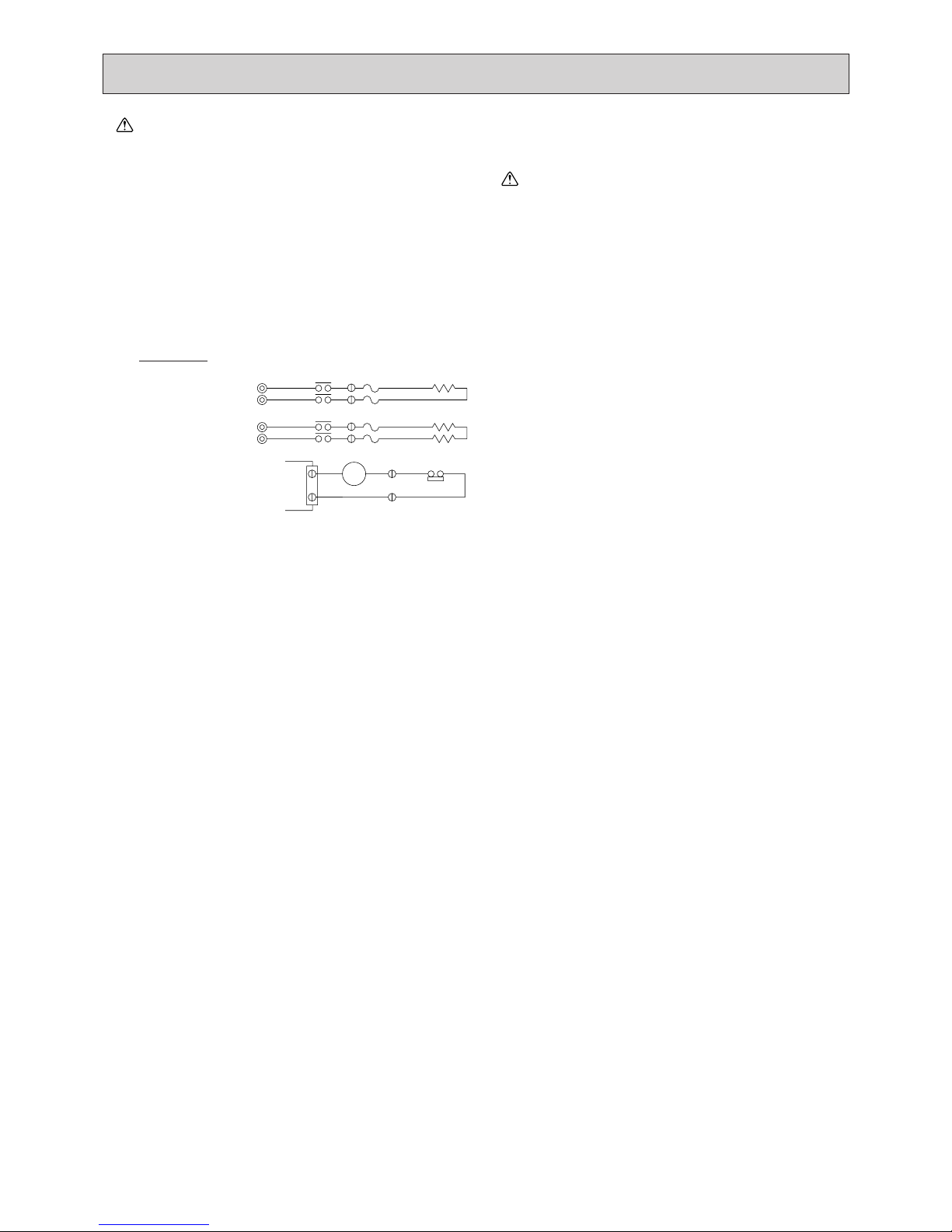
•
Recommended circuit
FS1
FS2
FS1
FS2
R
S
R
S
CN24
H2
88H
H1
88H
26H
88H
Wiring diagram
1-phase power
supply
208V, 230V/60Hz
Control board
FS1, 2 ----- Thermal fuse
H1, H2 ----- Heater
26H --------- Overheat protection
thermostat
88H --------- Electromagnetic contactor
3
PEFY-P30NMHU-E-F
PEFY-P54NMHU-E-F
PEFY-P72NMHU-E-F
PEFY-P96NMHU-E-F
8.8 / 8.4
15.8 / 14.9
21.1 / 19.9
28.1 / 26.4
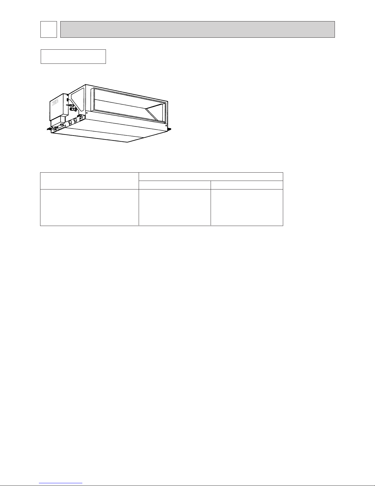
FEATURES
1
Indoor unit
Ceiling Concealed
Series PEFY
Models
Cooling capacity/Heating capacity
kW
30000 / 28500
54000 / 51000
72000 / 68000
96000 / 90000
BTU / h
4
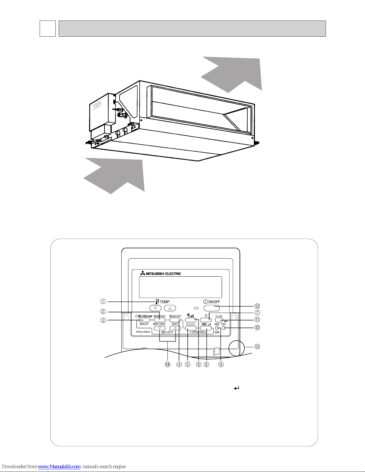
PART NAMES AND FUNCTIONS
2
● Indoor (Main) Unit
● Remote controller
[Operation buttons]
[PAR-21MAA]
● Once the controls are set, the same operation mode can
be repeated by simply pressing the ON/OFF button.
Air inlet
Air outlet
1 [Set Temperature] Button
2 [Timer Menu] Button
[Monitor/Set] Button
3 [Mode] Button
[Return] Button
4 [Timer On/Off] Button
[Set Day] Button
7 [Airflow Up/Down] Button
[Ventilation] Button
[Operation] Button
5 [Louver] Button
[Operation] Button
6 [Fan Speed] Button
[Check/Clear] Button
0 [Test run] Button
A
8
9
[Filter] Button
[ ] Button
B
C
D
[ON/OFF] Button
Position of built-in room temperature
[Set Time] Button
Ne• ver expose the remote controller to direct sunlight. Doing so can result in the erroneous measurement of room temperature.
• Never place any obstacle around the lower right-hand section of the remote controller. Doing so can
result in the erroneous measurement of room temperature.
PAR-21MAA
ON/OFF
FILTER
CHECK
OPERATION
CLEAR
TEST
TEMP.
MENU
BACK DAY
MONITOR/SET
CLOCK
ON/OFF
1
2
3
4D 568 9
0
C
A
B
7
5
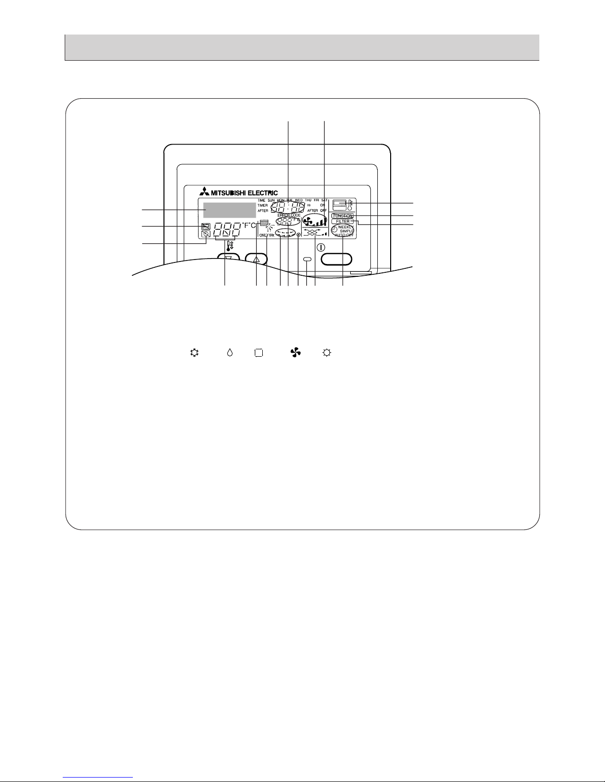
[Display]
C
C
ON/OFF
CENTRALLY CONTROLLED
ERROR CODE
CLOCK
ON OFF
CHECK
CHECK MODE
FILTER
TEST RUN
FUNCTION
1Hr.
NOT AVAILABLE
STAND BY
DEFROST
TEMP.
A
B
C
E
P
M
F
K
D
OLGNIHJQ
A
Current time/Timer
B
Centralized control
C
Timer OFF
D
Timer indicator
E
Operation mode: COOL, DRY, AUTO, FAN, HEAT
F
“Locked” indicator
G
H
Set temperature
I
Power ON
J
Louver
K
L
Ventilation
M
N
O
P
Filter sign
Set effective for 1 hr.
Sensor position
Room temperature
Airflow
Fan speed
3
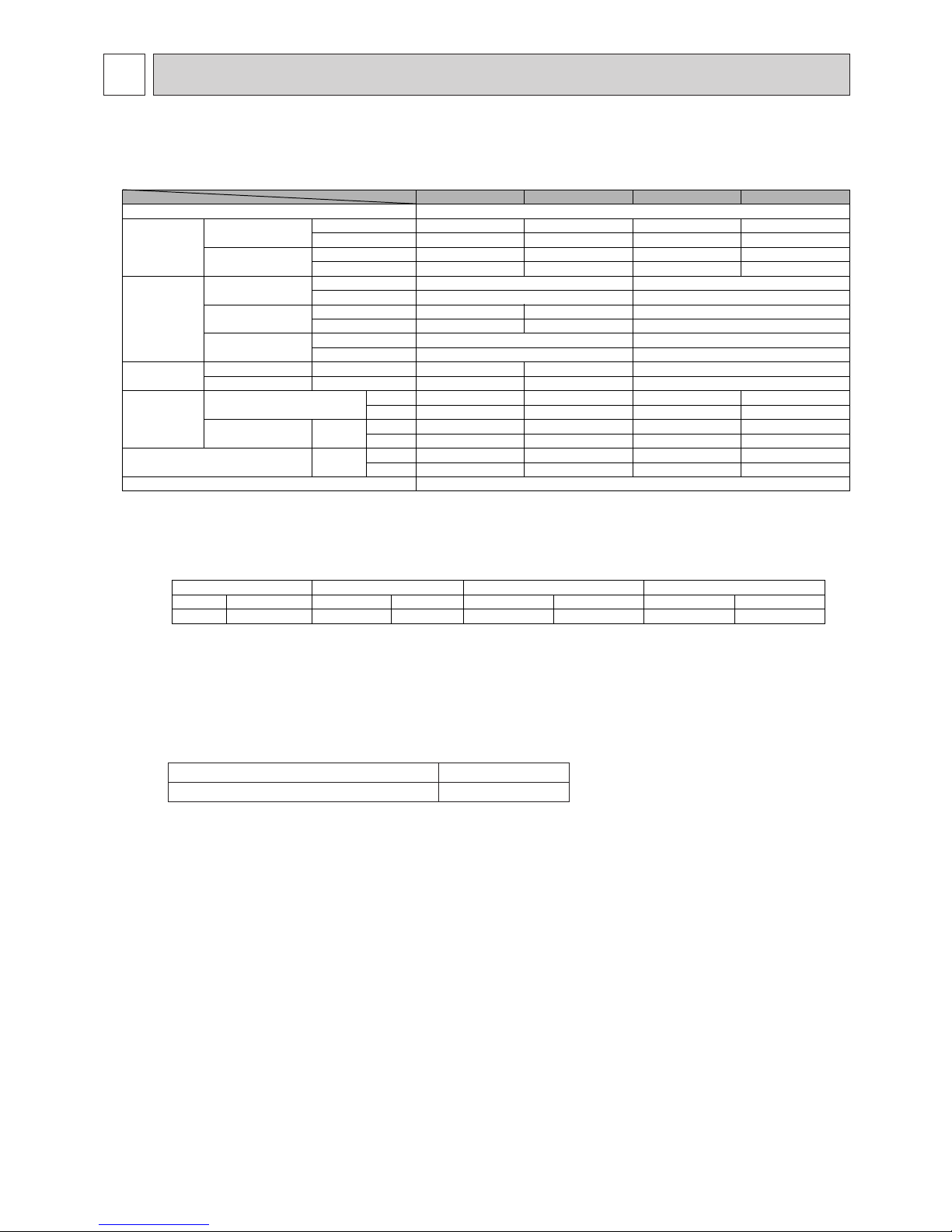
SPECIFICATION
3-1. Specification
a). The cooling and heating capacities are the maximum capacities that were obtained by operating in the above air conditions
and with a refrigerant pipe of about 7.5m.
b). The actual capacity characteristics vary with the combination of indoor and outdoor units. See the technical information.
c). The operating noise is the data that was obtained by measuring it 1.5m from the bottom of the unit in an anechoic room.
(Noise meter A-scale value)
d). The figures of Electrical characteristic of P30 and P54 models indicate at middle external static pressure,
electrical characteristic of P72 and P96 models indicate at high external static pressure.
e). When the 100% fresh air indoor units are connected, the maximum connectable indoor units to 1 outdoor unit are as follows.
f ). Operational temp range is cooling : from 21˚C[70˚F]DB/15.5˚C[60˚F] WB to 43˚C[109˚F]DB/35˚C[95˚F]WB.
Heating : from -10˚C[14˚F]DB to 20˚C[68˚F]DB
✻Thermo off (Fan) operation automatically starts either when temperature is lower than 21˚CDB in cooling mode or when
the temperature exceeds 20˚C[68˚F]DB in heating mode.
g ). As the room temp is sensed by the thermo in the remote controller or the one in the room, be sure to use ether remote
controller or room thermo.
h ). Dry mode is Not available. Fan mode operation during the thermo off in Cooling/Heating mode.
i ). The fan would temporarily stops either with R2/WR2 system or in defrost.
j ). In any case, the air flow rate should be kept lower than 110% of the above chart.Please see “ Fan curves “ for the details.
k ). When this unit is used as sole A/C system, be careful about the dew in air outlet grilles in cooling mode.
l ). Un-conditioned outdoor air such as humid air or cold air blows to the indoor during thermo off operation.
Please be careful when positioning indoor unit air outlet grilles, ie take the necessary precautions for cold air, and also
insulate rooms for dew condensation prevention as required.
m). Air filter must be installed in the air intake side.The filter should be attached where easy maintenance is possible in case of
usage of field supply filters.
n ). Long life filter cannot be used with Hi-efficiency filter together.
Heat pump models Cooling only
110%(100% in case of heating below-5
˚C) 110%
PEFY-P-NMHU-E-F
Notes: *1 Cooling/Heating capacity indicates the maximum value at operation under the following condition.
Cooling: Indoor: 33
˚C [91 ˚ F] DB/28 ˚C [82 ˚F] WB Outdoor: 33 ˚C [91 ˚F] DB
Heating: Indoor: 0
˚C [32 ˚ F] DB/-2. 9 ˚C [27 ˚F] WB Outdoor: 0 ˚C [32 ˚ F] DB/- 2.9 ˚C [27 ˚F] WB
*2 The operating noise is the data that was obtained in an anechoic room.
*3 As for the factory setting is below.
PEFY-P-NMHU-E-F series
Item Model
PEFY-P30NMHU-E-F PEFY-P54NMHU-E-F PEFY-P72NMHU-E-F PEFY-P96NMHU-E-F
Power sourse 208/230V, 60Hz
Capacity
*1
Cooling
kW 8.8 15.8 21.1 28.1
BTU/h 30000 54000 72000 96000
Heating
kW 8.4 14.9 19.9 26.4
BTU/h 28500 51000 68000 90000
Dimension
Height
mm 380 470
in 14-31/32 18-17/32
Width
mm 1000 1200 1250
in 39-3/8 47-1/4 49-7/32
Depth
mm 900 1120
in 35-7/16 44-1/8
Net weight
kg 50 70 100
lb 111 155 221
FAN
Airflow rate
m
3
/min9 182835
cfm 318 636 989 1236
External static
pressure *3
Pa
208V 35-85-170 35-85-170 180 180
230V 50-130-210 60-130-220 260 260
Noise level *2 dB(A)
208V 38 38 43 44
230V 43 43 47 48
Filter Standard filter
PEFY-P30NMHU-E-F PEFY-P54NMHU-E-F PEFY-P72NMHU-E-F PEFY-P96NMHU-E-F
208V 230V 208V 230V 208V 230V 208V 230V
85 130 85 130 180 260 180 260
6
7
LEV
C1
MF1,2
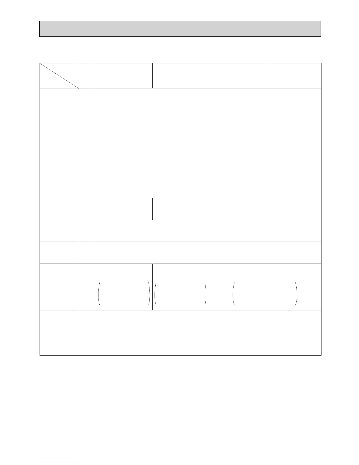
3-2. Electrical parts specifications
Model
Parts
name
Tranrsformer T (Primary) 50/60Hz 220-240V (Secondry) (23.5V 0.9A)
TH22
Resistance 0˚C[32˚F]/15kΩ,10˚C[50˚F]/9.6kΩ,20˚C[68˚F]/6.3kΩ,25˚C[77˚F]/5.4kΩ,
30˚C[86˚F]/4.3kΩ,40˚C[104˚F]/3.0kΩ
Resistance 0˚C[32˚F]/15kΩ,10˚C[50˚F]/9.6kΩ,20˚C[68˚F]/6.3kΩ,25˚C[77˚F]/5.4kΩ,
30˚C[86˚F]/4.3kΩ,40˚C[104˚F]/3.0kΩ
Resistance 0˚C[32˚F]/15kΩ,10˚C[50˚F]/9.6kΩ,20˚C[68˚F]/6.3kΩ,25˚C[77˚F]/5.4kΩ,
30˚C[86˚F]/4.3kΩ,40˚C[104˚F]/3.0kΩ
Gas pipe
thermistor
FUSE 250V 6.3A
TB2 (L1,L2,G) 330V 30A
TB5
TB15
(1,2),(M1,M2,S) 300V 10A
Fuse
(Indoor con-
troller board)
Power supply
terminal block
Transmission
terminal block
PEFY-P30NMHU-E-F PEFY-P54NMHU-E-F PEFY-P72NMHU-E-F PEFY-P96NMHU-E-F
OFF 135˚C±5˚C[275˚F±41˚F]
ON 95˚C±20˚C[203˚F±59˚F]
temperature
Outdoor air
thermistor
Fan motor
(with Inner-
thermostat)
Symbol
(L1,L2,L3,G) 660V 40A
TH23
TH24
Innerthermostat
(F
an motor)
Liquid pipe
thermistor
Fan motor
capacitor
Linear
expansion valve
4-pole OUTPUT 130W
NS-100VMHF
4-pole OUTPUT 200W
NS-224M-C-F
4-pole OUTPUT 230W
NS-280M-C-F
4-pole OUTPUT 90W
NS-80VMHF
4.0µF✕440V
-
0~1800pulse
<at R410A outdoor unit>
0~2000pulse
<at the other outdoor unit>
DC12V Stepping motor drive
port dimension ø 5.2
0~1800pulse
<at R410A outdoor unit>
0~2000pulse
<at the other outdoor unit>
DC12V Stepping motor drive
port dimension ø 6.4
0~1800pulse
<at R410A outdoor unit>
0~2000pulse
<at the other outdoor unit>
DC12V Stepping motor drive
port dimension ø 5.2
8
4
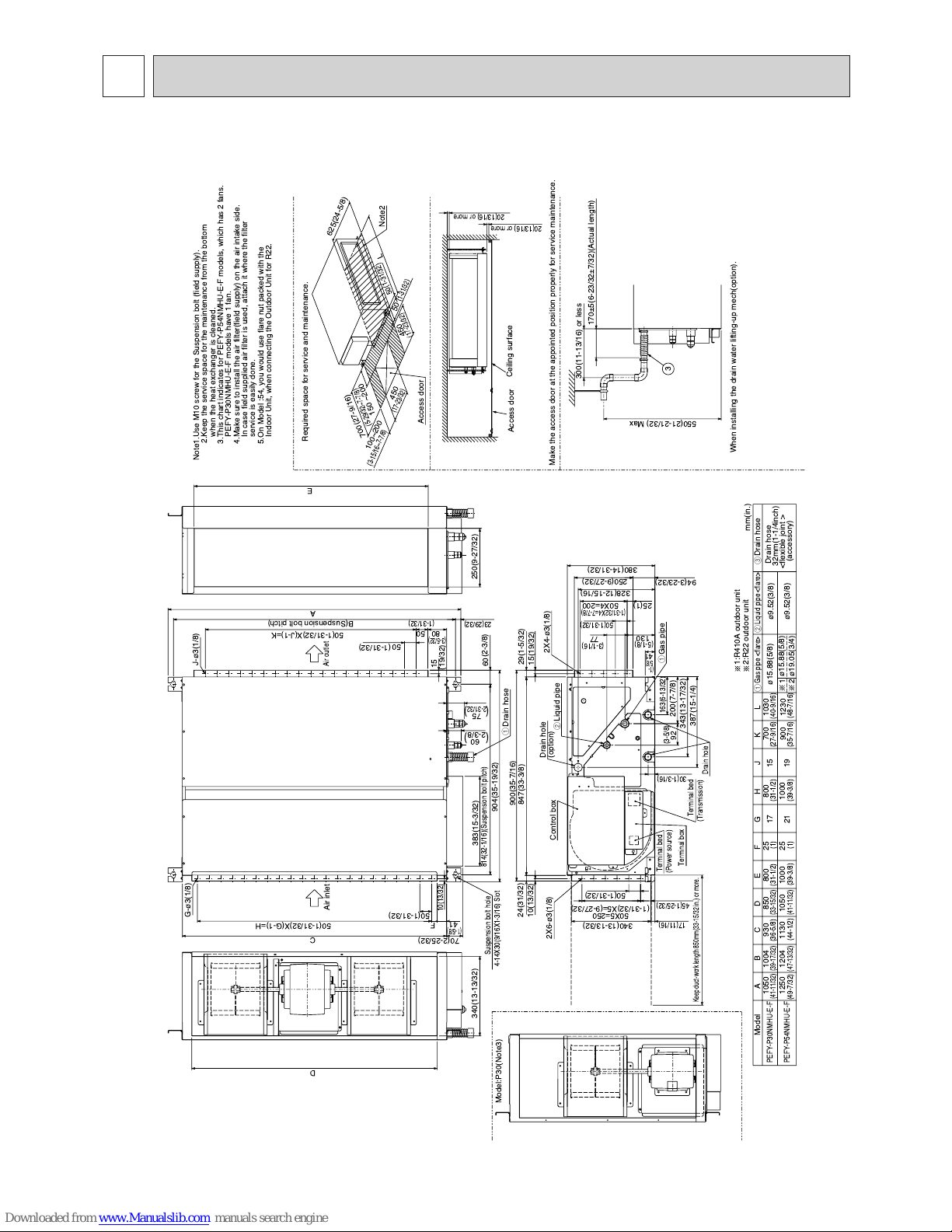
OUTLINES AND DIMENSIONS
Unit :mm(in.)
PEFY-P30·54NMHU-E-F
1:R410A outdoor unit
2:R22 outdoor unit
Air outlet
Air inlet
Model:P30(Note3)
mm(in.)
When installing the drain water lifting-up mech(option).
2X4-
¿3(1/8)
2X6-
¿3(1/8)
Drain hose
Liquid pipe <flare>Gas pipe <flare>
19
900 1230
15
700 1030
1204 1130
1004 930 850
1050 1000
800
25
21
1000
25
17
800
1250
1050
Drain hose
Required space for service and maintenance.
150 ~200
700
50
50
L
625
Note2
Access door
450
100~200
450
Terminal bed
(Power source)
Drain hole
(option)
Control box
Drain hole
Terminal box
Liquid pipe
Terminal bed
(Transmission)
Gas pipe
¿9.52(3/8)
¿9.52(3/8)
¿15.88(5/8)
1
2
¿19.05(3/4)
¿15.88(5/8)
Drain hose
32mm(1-1/4inch)
<flexible joint >
(accessory)
PEFY-P54NMHU-E-F
PEFY-P30NMHU-E-F
Model A B C D E F G H J K L
3
5.On Model :54, you would use flare nut packed with the
Indoor Unit, when connecting the Outdoor Unit for R22.
Make the access door at the appointed position properly for service maintenance.
Access door
Ceiling surface
Note1.Use M10 screw for the Suspension bolt (field supply).
2.Keep the service space for the maintenance from the bottom
when the heat exchanger is cleaned.
3.This chart indicates for PEFY-P54NMHU-E-F models, which has 2 fans.
PEFY-P30NMHU-E-F models have 1 fan.
4.Make sure to install the air filter(field supply) on the air intake side.
In case field supplied air filter is used, attach it where the filter
service is easily done.
Suspension bolt hole
G-¿3(1/8)
J-
¿3(1/8)
70(2-25/32)
C
41
50X5=250
41
92
163(6-13/32)
45(1-25/32)
17(11/16)
130
77
50(1-31/32)
50X4=20025
75
60
D
B(Suspension bolt pitch)
A
60
15
80
50
10(13/32)
F
50
E
Keep duct-work length 850mm(33-15/32 in.) or more.
(1-31/32)
(24-5/8)
(1-31/32)
(27-9/16)
(5-29/32~7-7/8)
(17-23/32)
(3-15/16~7-7/8)
(17-23/32)
(3-5/8)
(1-
5/8)
(5-1/8)
(3-1/16)
(1-31/32X4=7-7/8)
(1-5/8)
2-3/8
2-31/32
(19/32)
(1-31/32)
(3-5/32)
(35-7/16)
(48-7/16)
(27-9/16)
(40-9/16)
(47-13/32)
(44-1/2)
(39-17/32)
(36-5/8)
(33-15/32)
(41-11/32)
(39-3/8)
(31-1/2)
(1) (39-3/8)
(1)
(31-1/2)
(49-7/32)
(41-11/32)
4-14X30(9/16X1-3/16) Slot
24(31/32)
50(1-31/32)
10(13/32)
340(13-13/32)
900(35-7/16)
847(33-3/8)
15(19/32)
29(1-5/32)
387(15-1/4)
343(13-17/32)
200(7-7/8)
(1-31/32)X5=(9-27/32)
(1)
328(12-15/16)
250(9-27/32)
94(3-23/32)
380(14-31/32)
300(11-13/16) or less
550(21-21/32) Max
50(1-31/32)X(G-1)=H
170±5(6-23/32±7/32)(Actual length)
30(1-3/16)
20(13/16) or more
50(1-31/32)
20(13/16) or more
340(13-13/32)
814(32-1/16)(Suspension bolt pitch)
904(35-19/32)
383(15-3/32)
(2-3/8)
23(29/32)
(1-31/32)
50(1-31/32)X(J-1)=K
250(9-27/32)
321
1
1
2
()
()
9
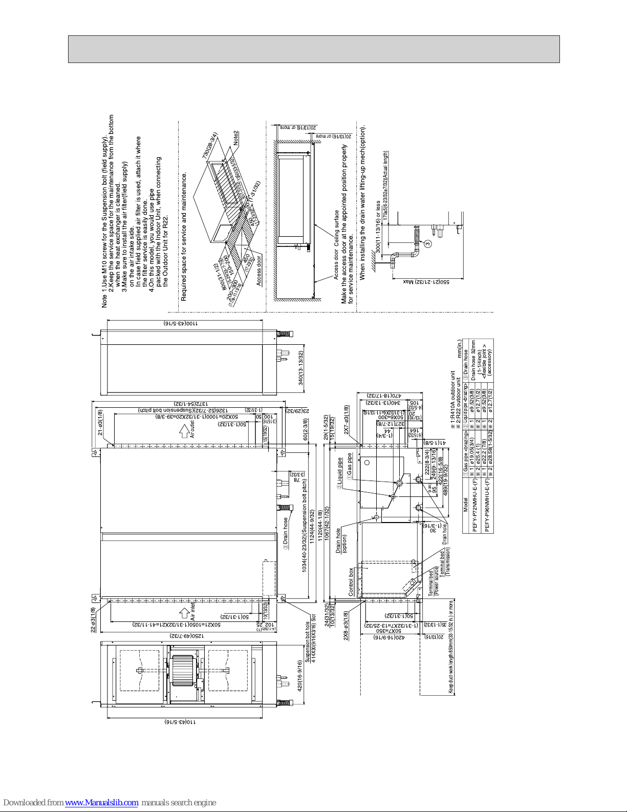
PEFY-P72·96NMHU-E-F
Unit : mm(in.)
1:R410A outdoor unit
2:R22 outdoor unit
Air inlet
Air outlet
mm(in.)
When installing the drain water lifting-up mech(option).
2X8-¿3(1/8)
2X7-
¿3(1/8)
Drain hose 32mm
<flexible joint >
(accessory)
Drain hose
¿9.52(3/8)
¿12.7(1/2)
¿9.52(3/8)
¿12.7(1/2)
PEFY-P72NMHU-E-(F)
¿19.05(3/4)
¿25.4 (1)
¿22.2 (7/8)
¿28.58(1-5/32)
PEFY-P96NMHU-E-(F)
Liquid pipe
Drain hose
Liquid pipe <brazing>
Gas pipe <brazing>
Gas pipe
3
Required space for service and maintenance.
Note2
Access door
450
200~300
450
730
(28-3/4)
50
150~200
Drain hole
(option)
Control box
Access door
Drain hole
22-¿3(1/8)
21-
¿3(1/8)
Model
Suspension bolt hole
Terminal bed
(Transmission)
Terminal bed
(Power source)
Make the access door at the appointed position properly
for service maintenance.
Ceiling surface
1.Use M10 screw for the Suspension bolt (field supply).
2.Keep the service space for the maintenance from the bottom
when the heat exchanger is cleaned.
3.Make sure to install the air filter(field supply)
on the air intake side.
In case field supplied air filter is used, attach it where
the filter service is easily done.
4.On this model, you would use pipe
packed with the Indoor Unit, when connecting
the Outdoor Unit for R22.
Note
221
1
221
1
50(1-31/32)
50(1-31/32)
60(2-3/8)
95
20
164
44
105
20(13/16)
35(1-13/32)
100
15
50
102 25
30
50X7=350
50X6=300
(1-1/4inch)
4-14X30(9/16X3/16) Slot
Keep duct-work length 850mm(33-15/32 in.) or more.
(3-3/32)
(4-1/32)
(1)
(3-3/4)
(6-15/32)
(1-3/4)
(13/16)
(4-5/32)
(19/32)
(1-31/32)
(3-15/16)
1350
(53-5/32)
800
(31-1/2)
(5-29/32~7-7/8)
(7-7/8~11-13/16)
(17-23/32)
(17-23/32)
(1-31/32)
50
(1-31/32)
50(1-31/32)
(1-3/16)
550(21-21/32) Max
222(8-3/4)
(1-31/32X7=13-25/32)
(1-31/32X6=11-13/16)
300(11-13/16) or less
78
170±5(6-23/32±7/32)(Actual length)
1100(43-5/16)
340(13-13/32)
1034(40-23/32)(Suspension bolt pitch)
1124(44-9/32)
420(16-9/16)
110(43-5/16)
1372(54-1/32)
1326(52-7/32)(Suspension bolt pitch)
23(29/32)
249(9-13/16)
422(16-5/8)
489(19-9/32)
41(1-5/8)
340(13-13/32)
470(18-17/32)
29(1-5/32)
15(19/32)
1067(42-1/32)
10(13/32)
1120(44-1/8)
420(16-9/16)
50X20=1000(1-31/32X20=39-3/8)
50X21=1050(1-31/32X21=41-11/32)
1250(49-7/32)
327(12-7/8)
20(13/16) or more
20(13/16) or more
10(13/32)
24(31/32)
321
3
2
1
 Loading...