

Mitsubishi A1SJH(S8), A1SH, A2SHCPU (S1) User Manual

SAFETY PRECAUTIONS
(Be sure to read these instructions before use.)
Before using the product, read this and relevant manuals carefully and handle the product correctly with full
attention to safety.
In this manual, SAFETY PRECAUTIONS are classified into 2 levels: "DANGER" and "CAUTION".
DANGER
CAUTION
Under some circumstances, failure to observe the CAUTION level instructions may also lead to serious
results.
Be sure to observe the instructions of both levels to ensure the safety.
Please keep this manual in a safe place for future reference and also pass this manual on to the end user.
Indicates that incorrect handling may cause hazardous conditions, resulting in
death or severe injury.
Indicates that incorrect handling may cause hazardous conditions, resulting in
medium or slight personal injury or physical damage.
[DESIGN PRECAUTIONS]
DANGER
Create a safety circuit outside the programmable controller to ensure the whole system will operate
safely even if an external power failure or a programmable controller failure occurs.
Otherwise, incorrect output or malfunction may cause an accident.
(1) For an emergency stop circuit, protection circuit and interlock circuit that is designed for
incompatible actions such as forward/reverse rotation or for damage prevention such as the
upper/lower limit setting in positioning, any of them must be created outside the programmable
controller.
Install the emergency stop switch outsid the controlpanel so that workers can operate it easily.
(2) When the programmable controller detects the following error conditions, it stops the operation
and turn off all the outputs.
• The overcurrent protection device or overvoltage protection device of the power supply
module is activated.
• The programmable controller CPU detects an error such as a watchdog timer error by the
self-diagnostics function.
In the case of an error of a part such as an I/O control part that cannot be detected by the
programmable controller CPU, all the outputs may turn on.In order to make all machines
operate safely in such a case, set up a fail-safe circuit or a specific mechanism outside the
programmable controller. For a fail-safe circuit example, refer to "LOADING AND
INSTALLATION" in this manual.
(3) Depending on the failure of the output module's relay or transistor, the output status may remain
ON or OFF incorrectly.
For output signals that may lead to a serious accident, create an external monitoring circuit.
A - 1
[DESIGN PRECAUTIONS]
DANGER
If load current more than the rating or overcurrent due to a short circuit in the load has flowed in the
output module for a long time, it may cause a fire and smoke.
as a fuse.
Design a circuit so that the external power will be supplied after power-up of the programmable
controller.
Activating the external power supply prior to the programmable controller may result in an accident
due to incorrect output or malfunction.
For the operation status of each station at a communication error in data link, refer to the respective
data link manual.
The communication error may result in an accident due to incorrect output or malfunction.
When controlling a running programmable controller (data modification) by connecting a peripheral
device to the CPU module or a PC to a special function module, create an interlock circuit on
sequence programs so that the whole system functions safely all the time.
Also, before performing any other controls (e.g. program modification, operating status change
(status control)), read the manual carefully and ensure the safety.
In these controls, especially the one from an external device to a programmable controller in a
remote location, some programmable controller side problem may not be resolved immediately due
to failure of data communications.
To prevent this, create an interlock circuit on sequence programs and establish corrective
procedures for communication failure between the external device and the programmable controller
CPU.
Provide an external safety device such
When setting up the system, do not allow any empty slot on the base unit.
If any slot is left empty, be sure to use a blank cover (A1SG60) or a dummy module (A1SG62) for it.
When using the extension base unit, A1S52B(S1), A1S55B(S1) or A1S58B(S1), attach the included
dustproof cover to the module in slot 0.
Otherwise, internal parts of the module may be flied in the short circuit test or when an overcurrent or
overvoltage is accidentally applied to the external I/O section.
[DESIGN PRECAUTIONS]
CAUTION
Do not install the control lines or communication cables together with the main circuit or power lines,
or bring them close to each other.
Keep a distance of 100mm (3.94inch) or more between them.
Failure to do so may cause malfunctions due to noise.
When an output module is used to control the lamp load, heater, solenoid valve, etc., a large current
(ten times larger than the normal one) may flow at the time that the output status changes from OFF
to ON. Take some preventive measures such as replacing the output module with the one of a
suitable current rating.
A - 2
[INSTALLATION PRECAUTIONS]
CAUTION
Use the programmable controller under the environment specified in the user's manual.
Otherwise, it may cause electric shocks, fires, malfunctions, product deterioration or damage.
Insert the module fixing projection into the fixing hole in the base unit and then tighten the module
fixing screw within the specified torque.
When no screw is tightened, even if the module is installed correctly, it may cause malfunctions, a
failure or a drop of the module.
Tightening the screw excessively may damage the screw and/or the module, resulting in a drop of
the module, a short circuit or malfunctions.
Connect the extension cable to the connector of the base unit or module.
Check for incomplete connection after installing it.
Poor electrical contact may cause incorrect inputs and/or outputs.
Insert the memory cassette and fully press it to the memory cassette connector.
Check for incomplete connection after installing it.
Poor electrical contact may cause malfunctions.
Be sure to shut off all phases of the external power supply used by the system before mounting or
removing the module.
Failure to do so may damage the module.
Do not directly touch the conductive part or electronic components of the module.
Doing so may cause malfunctions or a failure of the module.
A - 3
[WIRING PRECAUTIONS]
DANGER
Be sure to shut off all phases of the external power supply used by the system before wiring.
Failure to do so may result in an electric shock or damage of the product.
Before energizing and operating the system after wiring, be sure to attach the terminal cover
supplied with the product.
Failure to do so may cause an electric shock.
CAUTION
Ground the FG and LG terminals correctly.
Failure to do so may cause an electric shock or malfunctions.
Wire the module correctly after confirming the rated voltage and terminal layout.
Connecting a power supply of a different voltage rating or incorrect wiring may cause a fire or failure.
Do not connect multiple power supply modules to one module in parallel.
The power supply modules may be heated, resulting in a fire or failure.
Press, crimp or properly solder the connector for external connection with the specified tool.
Incomplete connection may cause a short circuit, fire or malfunctions.
Tighten terminal screws within the specified torque range.
If the screw is too loose, it may cause a short circuit, fire or malfunctions.
Tightening the screw excessively may damage the screw and/or the module, resulting in a drop of
the module, a short circuit or malfunctions.
Carefully prevent foreign matter such as dust or wire chips from entering the module.
Failure to do so may cause a fire, failure or malfunctions.
Install our programmable controller in a control panel for use.
Wire the main power supply to the power supply module installed in a control panel through a
distribution terminal block.
Furthermore, the wiring and replacement of a power supply module have to be performed by a
maintenance worker who acquainted with shock protection.
(For the wiring methods, refer to Section 8.7.)
A - 4
[STARTUP AND MAINTENANCE PRECAUTIONS]
DANGER
Do not touch any terminal during power distribution.
Doing so may cause an electric shock.
Properly connect batteries.
Do not charge, disassemble, heat or throw them into the fire and do not make them short-circuited
and soldered.
Incorrect battery handling may cause personal injuries or a fire due to exothermic heat, burst and/or
ignition.
Be sure to shut off all phases of the external power supply used by the system before cleaning or
retightening the terminal screws or module mounting screws.
Failure to do so may result in an electric shock.
If they are too loose, it may cause a short circuit or malfunctions.
Tightening the screw excessively may damage the screw and/or the module, resulting in a drop of
the module, a short circuit or malfunctions.
A - 5
CAUTION
When performing online operations (especially, program modification, forced output or operating
status change) by connecting a peripheral device to the running CPU module, read the manual
carefully and ensure the safety.
Incorrect operation will cause mechanical damage or accidents.
Do not disassemble or modify each of modules.
Doing so may cause failure, malfunctions, personal injuries and/or a fire.
When using a wireless communication device such as a mobile phone, keep a distance of 25cm
(9.84inch) or more from the programmable controller in all directions.
Failure to do so may cause malfunctions.
Be sure to shut off all phases of the external power supply used by the system before mounting or
removing the module.
Failure to do so may result in failure or malfunctions of the module.
Do not drop or apply any impact to the battery.
Doing so may damage the battery, resulting in electrolyte spillage inside the battery.
If any impact has been applied, discard the battery and never use it.
Do not mount/remove the module onto/from base unit more than 50 times (IEC61131-2-compliant),
after the first use of the product.
Before handling modules, touch a grounded metal object to discharge the static electricity from the
human body.
Failure to do so may cause failure or malfunctions of the module.
A - 6
[DISPOSAL PRECAUTIONS]
CAUTION
When disposing of the product, treat it as an industrial waste.
When disposing of batteries, separate them from other wastes according to the local regulations.
(For details of the battery directive in EU member states, refer to Appendix 6.)
[TRANSPORTATION PRECAUTIONS]
CAUTION
When transporting lithium batteries, make sure to treat them based on the transportation regulations.
(Refer to Appendix 5 for details of the relevant models.)
A - 7
Revision
*The manual number is given on the bottom left of the back cover.
Print Date *Manual Number Revision
May., 1997 IB(NA)66779-A First edition
Nov., 1997 IB(NA)66779-B
Apr., 1998 IB(NA)-66779-C
Aug., 1998 IB(NA)-66779-D
Nov., 1998 IB(NA)-66779-E
Dec., 2002 IB(NA)-66779-F Equivalent to the Japanese version F
Dec., 2003 IB(NA)-66779-G
Correction
Contents, Related manuals, Section 1.1, Section 2.1.1, 2.1.2, Section 2.2, 2.3,
Chapter 3, Section 4.1.6, Section 5.1, 5.2, Section 6.1.2, Section 8.7.1, 8.7.2,
Section 9.1.3, Section 11.3.1, Appendix 1, 1.1, Appendix 3.1, 3.2, Appendix 5.
Correction
SAFETY PRECAUTIONS, Contents, Section 1.1, Section 2.2, 2.3, Section 4.1,
4.1.7, 4.1.8, 4.1.9, 4.4.3, Section 6.1.3, Section 7.1.4, Section 8.7.1, Section
9.2.1, 9.2.2, Section 11.3.1, Appendix 1, 1.1, Appendix 3.1, 3.2, 3.3.3.
Correction
Section 2.2.1, 2.3, Section 4.1, Section 9.1.2.7, 9.1.2.9 Section 11.2.4, Appendix
2.2, 3.3.5
Addition of module
A1SJHCPU-S8
Correction
SAFETY PRECAUTIONS, Section 1.1, 1.2, Section 2.1.1, 2.1.2, 2.2.1, 2.2.2, 2.3,
Chapter 3, Section 4.1.1, 4.1.7, Section 5.1, 5.2, Section 6.1.3, Section 7.1.1,
Section 9.1.4, Chapter 10, Section 11.1.3, Appendix 2.1, 2.2, Appendix 4
Addition of module
A1SY42P
Oct., 2006 IB(NA)-66779-H
Correction
Section 2.2.1, 2.3, Section 7.1.1, 7.1.4, 7.2.1, Section 8.4.1, 8.8, Section 9.1.4,
Section 11.3.1, Appendix 2.1
Addition
Appendix 5
Correction
SAFETY PRECAUTIONS, Section 2.2.1, 2.3, Chapter 3, Section 4.1, 4.1.2, 4.1.3,
4.1.4, 4.1.7, 4.2, 4.3, 4.4.1, 4.4.3, 4.4.4, Section 5.1, 5.2, Section 6.1.2, 6.1.3, 6.2,
Section 7.1.1, 7.1.3, Section 8.1, 8.3, 8.4.1, 8.4.2, 8.5, 8.7.1, 8.7.2, 8.8, Chapter
9, Section 9.1.3, 9.2.6, Chapter 10, Section 10.2, 10.3.2, Section 11.2.8, 11.3.2,
11.4.1, 11.4.2, Appendix 2.1, 2.2, Appendix 4.5.1, WARRANTY
Addition
USER PRECAUTONS, Section 7.2.2, Section 11.2.9, 11.3.1
A - 8
Print Date *Manual Number Revision
May, 2007 IB(NA)-66779-I
Jul., 2007 IB(NA)-66779-J
Sep., 2008 IB(NA)-66779-K
Correction
Section 2.3, 8.7.1, 8.7.2, 9.1.3, 9.2.7, 10.3.1, 11.4.2
Addition
Section 9.1.7
Correction
Section 6.2, Appendix 4.4.1, Appendix 4.4.3, Appendix 4.4.4, Appendix 4.4.5,
Appendix 4.4.8, Appendix 4.4.9, Appendix 4.4.10
Correction
SAFETY PRECAUTIONS, Chapter 1, Section 2.2.2, 2.3, 2.4, Chapter 3,
Section 4.1, 4.1.1, 4.1.2, 4.1.3, 4.1.4, 4.1.5, 4.3, 4.4, 5.1, 8.1, 8.2, 8.3, 8.4.1,
8.4.2, 8.7.1, 8.7.2, 8.8, 9.1, 9.1.1, 9.1.2, 9.1.3, 9.2, 9.2.1, 9.2.2, 9.2.3, 9.2.4, 9.2.5,
9.2.6, 9.2.7, Chapter 10, Section 10.3.1, 10.3.2, 11.1, 11.2.3, 11.3, 11.4.1, 11.2.8,
Appendix 1, Appendix2.2
Addition
Appendix 6, Appendix 6.1, Appendix 6.2
Japanese Manual Version SH-3635-L
This manual confers no industrial property rights or any rights of any other kind, nor dose it confer any patent
licenses.Mitsubishi Electric Corporation cannot be held responsible for any problems involving industrial property rights
which may occur as a result of using the contents noted in this manual.
1997 MITSUBISHI ELECTRIC CORPORATION
A - 9

Introduction
Thank you for purchasing the Mitsubishi programmable logic controller MELSEC-A Series.
Prior to use, please read this manual thoroughly to fully understand the functions.
Please hand in a copy of this manual to the end user.
Table of Contents
1 OVERVIEW 1 - 1 to 1 - 4
1.1 Features ........................................................................................................................................1 - 2
2 SYSTEM CONFIGURATION 2 - 1 to 2 - 30
2.1 Overall Configuration.....................................................................................................................2 - 1
2.1.1 Overall configuration of AnSHCPU .......................................................................................2 - 1
2.1.2 Overall configuration of A1SJHCPU(S8)...............................................................................2 - 3
2.2 Precautions when Configuring the System ...................................................................................2 - 5
2.2.1 Hardware...............................................................................................................................2 - 5
2.2.2 Software package .................................................................................................................2 - 9
2.3 System Equipment ......................................................................................................................2 - 11
2.4 System Configuration Overview ..................................................................................................2 - 26
3 SPECIFICATIONS 3 - 1 to 3 - 1
4 CPU MODULE 4 - 1 to 4 - 29
4.1 Performance Specifications...........................................................................................................4 - 1
4.1.1 Overview of operation processing .........................................................................................4 - 4
4.1.2 Operation processing of RUN, STOP and PAUSE ...............................................................4 - 7
4.1.3 Operation processing upon instantaneous power failure ......................................................4 - 9
4.1.4 Self-diagnostics function .....................................................................................................4 - 10
4.1.5 Device list............................................................................................................................4 - 13
4.2 Parameter Setting Ranges ..........................................................................................................4 - 15
4.2.1 List of parameter setting range ...........................................................................................4 - 15
4.2.2 Memory capacity setting (for main program, file register, comment, etc.) ..........................4 - 17
4.3 Function List ................................................................................................................................4 - 19
4.4 Handling Precautions ..................................................................................................................4 - 21
4.5 Part Names .................................................................................................................................4 - 22
4.5.1 Parts names of the A1SHCPU, A2SHCPU(S1), A1SJHCPU (S8)......................................4 - 22
4.5.2 Setting of I/O control mode switching switch.......................................................................4 - 26
4.5.3 Settings for memory write protect switch ............................................................................4 - 27
4.5.4 Latch clear operation...........................................................................................................4 - 29
5 POWER SUPPLY MODULE 5 - 1 to 5 - 6
5.1 Specifications ................................................................................................................................5 - 1
5.1.1 Power supply module selection.............................................................................................5 - 4
5.2 Part Names ...................................................................................................................................5 - 5
A - 10

6 BASE UNIT AND EXTENSION CABLE 6 - 1 to 6 - 10
6.1 Specifications ................................................................................................................................6 - 1
6.1.1 Base unit specifications.........................................................................................................6 - 1
6.1.2 Extension cable specifications ..............................................................................................6 - 2
6.1.3 Application standards of extension base units (A1S52B(S1), A1S55B(S1), A1S58B(S1), A52B,
A55B, A58B) .........................................................................................................................6 - 3
6.2 Part Names ...................................................................................................................................6 - 7
6.3 Installation and Removal of DIN Rail.............................................................................................6 - 9
7 MEMORY CASSETTE AND BATTERY 7 - 1 to 7 - 8
7.1 Memory Cassette ..........................................................................................................................7 - 1
7.1.1 Specifications ........................................................................................................................7 - 1
7.1.2 Handling precautions ............................................................................................................7 - 2
7.1.3 Installation and removal of memory cassette........................................................................7 - 3
7.1.4 Writing a sequence program to a memory cassette..............................................................7 - 5
7.1.5 Memory protection setting of A2SNMCA-30KE ....................................................................7 - 6
7.2 Battery ...........................................................................................................................................7 - 7
7.2.1 Specifications ........................................................................................................................7 - 7
7.2.2 Handling precautions ............................................................................................................7 - 7
7.2.3 Battery installation.................................................................................................................7 - 8
8 LOADING AND INSTALLATION 8 - 1 to 8 - 23
8.1 Fail-Safe Circuit Concept ..............................................................................................................8 - 1
8.2 Installation Environment ................................................................................................................8 - 6
8.3 Calculation Method of Heat Amount Generated by the PLC .........................................................8 - 7
8.4 Installing the Base Units................................................................................................................8 - 9
8.4.1 Precautions when installing programmable controller...........................................................8 - 9
8.4.2 Installation ...........................................................................................................................8 - 10
8.5 Installation and Removal of the Base Units.................................................................................8 - 11
8.6 Installation and Removal of the Dustproof Cover........................................................................8 - 14
8.7 Wiring ..........................................................................................................................................8 - 16
8.7.1 Wiring instructions...............................................................................................................8 - 16
8.7.2 Wiring to module terminals..................................................................................................8 - 21
8.8 Precautions when Connecting the Uninterruptible Power Supply (UPS) ....................................8 - 23
9 EMC AND LOW VOLTAGE DIRECTIVES 9 - 1 to 9 - 13
9.1 Requirements for Compliance with EMC Directives......................................................................9 - 1
9.1.1 EMC standards .....................................................................................................................9 - 1
9.1.2 Installation instructions for EMC directive .............................................................................9 - 2
9.1.3 Cables ...................................................................................................................................9 - 3
9.1.4 Power supply module............................................................................................................9 - 8
9.1.5 Ferrite core............................................................................................................................9 - 8
9.1.6 Noise filter (power supply line filter) ......................................................................................9 - 9
9.1.7 Power line for external power supply terminal ......................................................................9 - 9
9.2 Requirements for Compliance with Low Voltage Directives........................................................9 - 10
A - 11

9.2.1 Standard applied for MELSEC-AnS series programmable controller .................................9 - 10
9.2.2 Precautions when using the MELSEC-AnS series programmable controller......................9 - 10
9.2.3 Power supply.......................................................................................................................9 - 11
9.2.4 Control panel.......................................................................................................................9 - 12
9.2.5 Module installation ..............................................................................................................9 - 13
9.2.6 Grounding ...........................................................................................................................9 - 13
9.2.7 External wiring.....................................................................................................................9 - 13
10 MAINTENANCE AND INSPECTION 10 - 1 to 10 - 8
10.1 Daily Inspection ...........................................................................................................................10 - 2
10.2 Periodic Inspection ......................................................................................................................10 - 3
10.3 Battery Replacement ...................................................................................................................10 - 4
10.3.1 Battery life ...........................................................................................................................10 - 4
10.3.2 Battery replacement procedure...........................................................................................10 - 8
11 TROUBLESHOOTING 11 - 1 to 11 - 22
11.1 Fundamentals of Troubleshooting ...............................................................................................11 - 1
11.2 Troubleshooting...........................................................................................................................11 - 2
11.2.1 Troubleshooting procedure .................................................................................................11 - 2
11.2.2 Flow for actions when the "POWER" LED is turned OFF ...................................................11 - 3
11.2.3 Flow for actions when the "RUN" LED is turned OFF .........................................................11 - 4
11.2.4 Flow for actions when the "RUN" LED is flickering .............................................................11 - 5
11.2.5 Flow for actions when the "ERROR" LED is turned ON......................................................11 - 6
11.2.6 Flow for actions when the "ERROR" LED is flickering ........................................................11 - 7
11.2.7 Flow for actions when the output module's output load does not turn ON ..........................11 - 8
11.2.8 Flow for actions when the program cannot be written.........................................................11 - 9
11.2.9 Flow for actions when the CPU module is not started up .................................................11 - 10
11.3 Error Code List ..........................................................................................................................11 - 11
11.3.1 Procedure to read an error code .......................................................................................11 - 11
11.3.2 AnSHCPU error code list ..................................................................................................11 - 12
11.4 Fault Examples with I/O Modules..............................................................................................11 - 17
11.4.1 Faults with the input circuit and the corrective actions ......................................................11 - 17
11.4.2 Faults in the output circuit .................................................................................................11 - 19
APPENDIX Appendix - 1 to Appendix - 57
Appendix 1 Instruction List .............................................................................................................. App - 1
Appendix 1.1 Precautions for write during RUN of a dedicated instruction .............................. App - 7
Appendix 2 LISTS OF SPECIAL RELAYS AND SPECIAL REGISTERS ...................................... App - 8
Appendix 2.1 List of Special Relays......................................................................................... App - 8
Appendix 2.2 Special Registers ............................................................................................. App - 20
Appendix 3 Precautions when Replacing AnSCPU with AnSHCPU ............................................. App - 39
Appendix 3.1 Differences between A1SHCPU and A1SCPU................................................. App - 39
Appendix 3.2 Differences between A2SHCPU(S1) and A2SCPU .......................................... App - 40
Appendix 3.3 Replacement precautions ................................................................................. App - 40
Appendix 3.3.1 PLC type setting ........................................................................................ App - 40
Appendix 3.3.2 Precautions when performing ROM partition ............................................. App - 40
A - 12

Appendix 3.3.3 Precautions when utilizing sequence programs ........................................ App - 41
Appendix 3.3.4 Checking the influence of the increased instruction processing speed on the
system ....................................................................................................... App - 41
Appendix 3.3.5 Handling conventional memory cassettes ................................................. App - 42
Appendix 3.3.6 Replacing the A2SMCA-14KP (when A2SCPU + A2SMCA-14KP has been used)
................................................................................................................... App - 42
Appendix 3.3.7 Restrictions on microcomputer programs .................................................. App - 42
Appendix 4 External Dimensions .................................................................................................. App - 43
Appendix 4.1 CPU module...................................................................................................... App - 43
Appendix 4.1.1 A1SHCPU, A2SHCPU(S1) module ........................................................... App - 43
Appendix 4.1.2 A1SJHCPU module ................................................................................... App - 43
Appendix 4.1.3 A1SJHCPU-S8 module.............................................................................. App - 44
Appendix 4.2 A1S61PN, A1S62PN and A1S63P power supply modules .............................. App - 45
Appendix 4.3 Main base unit................................................................................................... App - 46
Appendix 4.3.1 A1S32B main base unit ............................................................................. App - 46
Appendix 4.3.2 A1S33B main base unit ............................................................................. App - 46
Appendix 4.3.3 A1S35B main base unit ............................................................................. App - 47
Appendix 4.3.4 A1S38B main base unit ............................................................................. App - 47
Appendix 4.4 Extension base unit........................................................................................... App - 48
Appendix 4.4.1 A1S65B extension base unit...................................................................... App - 48
Appendix 4.4.2 A1S68B extension base unit...................................................................... App - 48
Appendix 4.4.3 A1S52B extension base unit...................................................................... App - 49
Appendix 4.4.4 A1S55B extension base unit...................................................................... App - 49
Appendix 4.4.5 A1S58B extension base unit...................................................................... App - 50
Appendix 4.4.6 A1S65B-S1 extension base unit ................................................................ App - 50
Appendix 4.4.7 A1S68B-S1 extension base unit ................................................................ App - 51
Appendix 4.4.8 A1S52B-S1 extension base unit ................................................................ App - 51
Appendix 4.4.9 A1S55B-S1 extension base unit ................................................................ App - 52
Appendix 4.4.10 A1S58B-S1 extension base unit................................................................ App - 52
Appendix 4.5 Memory cassette............................................................................................... App - 53
Appendix 4.5.1 AnSNMCA-[ ] memory cassette ................................................................. App - 53
Appendix 4.6 Memory write adapter ....................................................................................... App - 53
Appendix 4.6.1 A6WA-28P memory write adapter ............................................................. App - 53
Appendix 5 Transportation Precautions ........................................................................................ App - 54
Appendix 5.1 Relevant models ............................................................................................... App - 54
Appendix 5.2 Transportation Guidelines................................................................................. App - 55
Appendix 6 Handling of Batteries and Devices with Built-in Batteries in EU Countries ................ App - 56
Appendix 6.1 Disposal precautions......................................................................................... App - 56
Appendix 6.2 Exportation precautions .................................................................................... App - 57
INDEX Index - 1 to Index - 3
A - 13
About This Manual
Related manuals
The following manuals are related to this product.
Manual Name
ACPU/QCPU-A (A mode) Programming Manual (Fundamentals)
Describes programming methods necessary for creating programs, device names, parame-
ters, program types, memory area configuration, and so on. (Sold separately)
ACPU/QCPU-A (A mode) Programming Manual (Common Instructions)
Describes how to use the sequence instruction, basic instructions, applied instructions and
microcomputer programs. (Sold separately)
AnSHCPU/AnACPU/AnUCPU/QCPU-A (A Mode) Programming Manual (Dedicated Instructions)
Describes instructions that have been expanded for AnSHCPU
(Sold separately)
AnS Module type I/O User's Manual
Describes the specification of the compact building block type I/O module.
(Sold separately)
Manual No.
(Model Code)
IB-66249
(13J740)
IB-66250
(13J741)
IB-66251
(13J742)
IB-66541
(13JE81)
A - 14

USER PRECAUTIONS
Precautions when using the AnS series
For a new CPU module, which has never used before, the contents of built-in RAM and
device data are undefined.
Make sure to clear the built-in RAM memory (PLC memory all clear) in the CPU module by
peripheral devices and operate latch clear by RUN/STOP key switches.
Precautions for battery
(1) The operation after a battery is unmounted and the programmable controller is stored.
When reoperating after a battery is uncounted and the programmable controller is
stored, the contents of built-in RAM and device data may be undefined.
For this reason, make sure to clear the built-in RAM memory (PLC memory all clear) in
the CPU module by peripheral devices and operate latch clear by RUN/STOP key
switches before start the operation again.
After the built-in RAM clear and latch clear of the CPU module, write the backed-up
memory contents to the CPU module before saving.
(2) The operation after excess of a battery life
If a battery exceeded its guaranteed life is stored and reoperated, the contents of built-in
RAM and device data may be undefined.
For this reason, make sure to clear the built-in RAM memory (PLC memory all clear) in
the CPU module by peripheral devices and operate latch clear by RUN/STOP key
switches before start the operation again.
After the built-in RAM clear and latch clear of the CPU module, write the backed-up
memory contents to the CPU module before saving.
*
*
POINT
Make sure to back up each memory contents before storing the programmable
controller.
* Refer to the following manuals for details of built-in RAM clear (PLC memory all clear) by periph-
eral devices.
GX Developer Operating Manual
A6GPP/A6PHP Operating Manual
SW IVD-GPPA Operating Manual
Refer to Section 4.5 for latch clear operation by RUN/STOP key switch of the CPU module.
A - 15
1. OVERVIEW
1 OVERVIEW
This user's manual describes the functions, specification, and handling of the A1SJHCPU
general purpose programmable controller (abbreviated as A1SJHCPU from here on),
A1SJHCPU-S8 general purpose programmable controller (abbreviated as A1SJHCPUS8), A1SHCPU general purpose PLC (abbreviated as A1SHCPU), A2SHCPU general
purpose PLC (abbreviated as A2SHCPU), and A2SHCPU-S1 general purpose PLC
(abbreviated as A2SHCPU-S1).
A1SHCPU and A1SJHCPU are grouped as A1SHCPU, unless there is necessity to
identify each model.
Also, A1SHCPU, A2SHCPU and A2SHCPU-S1 are grouped as AnSHCPU, unless there
is necessity to identify each model.
The AnSHCPU is a compact-type building block programmable controller. The model is
one third the size of the conventional building block type programmable controller, and
allows easy operation in spite of its small size.
Sequence programs that have been created for the existing A0J2CPU, A0J2HCPU and
A NCPU models can be used by changing the CPU module type specification for the
program. Moreover, since modules for use with A NCPU can be used by installing them
on an extension base unit for A NCPU use, it is possible to extend the functions of an
AnSCPU.
This user's manual refers to peripheral devices by using the following abbreviations.
A6GPP, A6PHP, PC/AT (started up with SW IVD-GPPA)
......................................................... Abbreviated as "GPP function".
A7PUS, A8PUE .............................. Abbreviated as "PU".
1 - 1

1. OVERVIEW
1.1 Features
(1) High-speed operation processing speed
Compared to the conventional A1SCPU, the A1SHCPU is three times and A2SHCPU
(S1) is four times faster in the operation processing speed, respectively.
Item A1SHCPU A2SHCPU(S1) A1SCPU
Operation processing speed
*1 I/O processing: Refresh and LD instruction
*1
0.33 s 0.25 s 1 s
(2) Addition of new dedicated instructions
The CC-Link dedicated instructions (8 instructions) have been added, making the
operation even easier.
(3) Increased number of I/O device points
The actual number of I/O points is the same as the AnS series, but each CPU has
2048 points (X/Y0 to X/Y7FF) of I/O devices.
The added I/O device can be used as the MELSECNET (/B), MELSECNET/MINI-S3,
or CC-Link.
(4) Increased file register R capacity
The capacity is now max. 8192 points (R0 to R8191), which doubled the AnS series'
4096 points (R0 to R4095).
(5) Increased memory capacity (Increased number of comment points)
The A1SHCPU has 64 k bytes, which doubled the A1SCPU's 32 k bytes.
This increased the number of comment points stored in the CPU module 3648 points
in comparison to the 1600 points in A1SCPU.
(6) Full compatibility with A1S(S1)/A2SCPU(S1)
Because there is full compatibility of the functions and instructions with A1S(S1)/
A2SCPU(S1), all software packages can be used.
In addition, power supply module, base unit, and I/O modules can be used.
(7) Compact size
The appearance of the AnSHCPU system with one power supply module, one CPU,
and eight 16-point I/O modules for use with AnS mounted to the main base unit are:
430mm (16.9in.) (W); 130mm (5.12in.) (H); and 110mm (4.33in.) (D).
(8) Max. 8 k/14 k steps of program
An A1SHCPU allows the creation of a sequence program up to 8k steps, an
A2SHCPU(S1) allows up to 14k steps.
In addition, microcomputer programs and utility programs created by the user can be
used.
1 - 2
OVERVIEW1.
(9) SFC language compatible
An AnSCPU contains a microcomputer program area, so an SFC program can be
used.
(10) Two extension connectors, on the right and left sides. (A1SHCPU,A2SHCPU(S1))
In order to facilitate wiring wherever the extension base unit is installed, extension
connectors are provided at both left and right sides of the AnSHCPU and extension
cables that suit the requirements imposed by different mounting locations are
available.
* A1SJHCPU(S8) on the right side only
(11) Use either screws or DIN rail for panel installations
The AnS base unit is provided both with screw holes and, on its rear face, the fixture
for mounting it to a DIN rail.
(12) Easy-to-see terminal block symbol sheet
• A terminal block symbol sheet is attached to the front of AnS I/O modules.
AnSHCPU writes I/O device numbers, connector numbers, etc. on one side of the
sheet.
• Terminal symbols for 16 I/O signals can be written on the other side.
(13) A N, A A-series I/O module and special function module compatible
By connecting an A N, A A-series extension base unit, A N, A A I/O
modules or special function modules can be used.
(14) Same programming environment as other MELSEC-A CPU modules
A sequence program can be created using the peripheral device currently used for
other MELSEC-A CPU modules. For details on the applicable peripheral devices,
refer to Section 2.2 "Precautions when Configuring the System".
1 - 3

OVERVIEW1.
MEMO
1 - 4
2. SYSTEM CONFIGURATION
2 SYSTEM CONFIGURATION
This chapter describes the applicable system configurations, cautions on configuring a
system, and component devices of the AnSHCPU.
2.1 Overall Configuration
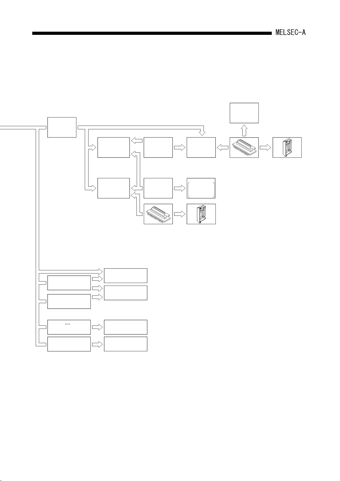
2.1.1 Overall configuration of AnSHCPU
The following figure shows configurations of an AnSHCPU stand-alone system and a
peripheral device.
(To peripheral devices)
ROM cassette
(A1SNMCA-8KP with EP-ROM)
(A1SNMCA- KE with E2PROM)
A1SHCPU
Main base(A1S3 B)
Battery (A6BAT)
A2SHCPU(S1)
ROM cassette
(A2SNMCA-30KE with E PROM)
Power supply module
Input module
Output module
Special function module
2
Power supply module
Input module
Output module
Special function module
Extension cable (A1SC0 NB)
[Building-block type]
Extension base
(A5 B)
: without a power supply module
(A6 B)
: with a power supply module
Extension cable (A1SC NB)
Extension base
(A1S5 B(S1))
: without a power supply module
(A1S6 B(S1))
: with a power supply module
2 - 1
SYSTEM CONFIGURATION2.
To CPU module
AC30R4
AC300R4
cable
AC30R4-PUS
cable
AC20R4-A8PU
cable
A6PHP
Plasma hand-held
graphic programmer
A6GPP intelligent
GPP
A7PUS
programming unit
A8PUE
programming unit
AC03WU
cable
AC30R2
cable
EP-ROM write adapter
(A6WA-28P)
A6WU
P-ROM writer
module
Printer
A7NPR-S1,
K6PR-K,
Generalpurpose printer
ROM cassette
(A1SNMCA-8KP)
ROM writer
*
EP-ROM write adapter
(A6WA-28P)
ROM cassette
(A1SNMCA-8KP)
RS-232C RS-422
converter
AC30R4-PUS
cable
IBM-PC/AT-compatible
personal computer
A6DU-B
data access module
2 - 2
SYSTEM CONFIGURATION2.
2.1.2 Overall configuration of A1SJHCPU(S8)
The following figure shows configurations of a A1SJHCPU(S8) stand-alone system and
peripheral device.
A1SJHCPU(S8)
Battery (A6BAT)
(To peripheral device)
Thin type I/O module (A1SJ-56 )
ROM cassette
A1SNMCA-8KP
with EP-ROM
A1SNMCA- KE
2
with E PROM
Extension cable (A1SC B)
Extension base
(A1S5 B(S1))
:Without a power supply module
(A1S6 B(S1))
:With a power supply module
Extension cable (A1SC05NB)
[Building block type]
Input module (A1SX )
Output module (A1SY )
Special function module
Power supply module (A1S6 P)
Extension base
(A5 B)
:Without a power supply module
(A6 B)
:With a power supply module
Input module (AX )
Power supply module (A6 P)
2 - 3
Output module (AY )
Special function module
Fuse
SYSTEM CONFIGURATION2.
(To A1SJHCPU(S8))
AC30R4
AC300R4
cable
AC30R4-PUS
cable
AC20R4-A8PU
cable
A6PHP
Plasma hand-held
graphic programmer
A6GPP
intelligent GPP
A7PUS
programming module
A8PUE
programming module
AC03WU
cable
AC30R2
cable
EP-ROM write adapter
(A6WA-28P)
A6WU
P-ROM writer
module
Printer
A7NPR-S1,
K6PR-K,
general-purpose
printer
ROM cassette
(A1SNMCA-8KP)
ROM writer
EP-ROM write
adapter
(A6WA-28P)
*
ROM cassette
(A1SNMCA-8KP)
RS-232C RS-422
conerter
AC30R4-PUS
cable
*1, *2
IBM PC/AT or
100% compatible
A6DU-B
data access module
*1:
Refer to SW0IX-GPPAE Software
Package Operating Manual or the
MELSEC-MEDOC Operating Manual for
connectable cables and devices.
*2:
IBM is a registered trademark of the
International Buisiness Machines Corporation.
2 - 4

2. SYSTEM CONFIGURATION
2.2 Precautions when Configuring the System
The hardware and software packages which can be used for the CPU module are
described.
2.2.1 Hardware
(1) I/O module
All the building-block-type I/O modules for A N and A A can be used by installing
them to the extension base module of A5 B/A6 B.
2 - 5
SYSTEM CONFIGURATION2.
(2) Special function module
(a) Special function modules for A N and A A can be used by installing them in
the extension base of A5 B/A6 B.
(b) Installation count of the following modules are limited of the special function
modules.
AD51H-S3
AJ71UC24
AJ71E71N-B5
AJ71C23-S3
AJ61BT11 (Only when the intelligent mode is used.)
GOT-A900 Series (Only when the bus connection is
*1
used.)
GOT1000 Series (Only when the bus connection is
*1
used.)
A1SJ71UC24-R2(PRF/R4)
A1SJ71E71N-B2
A1SJ71E71N-B5T
A1SD51S A1SD21-S1
A1SJ61BT11 (Only when the intelligent mode is
used.)
AI61(S1)
A1SI61
AJ71AP21(S3)
AJ71AT21B
A1SJ71AP21(S3)
A1SJ71AT21B
AJ71LP21(G/GE)
AJ71LR21
AJ71C22-S1
AJ71E71N-B2
AJ71E71N-T
AD22-S1
AJ71AR21
A1SJ71AR21
AJ71BR11
Up to 2 modules in total can be installed.
Only one module can be installed.
Only one module can be installed.
A1SJ71LP21(GE)
A1SJ71LR21
AJ71PT32-S3 (Only when the extension mode is
used.)
AJ71T32-S3 (Only when the extension mode is
used.)
A1SJ71PT32-S3 (Only when the extension mode is
used.)
A1SJ71T32-S3 (Only when the extension mode is
used.)
*1 Refer to the following manual for the GOT model names.
GOT-A900 Series User's Manual (GT Work2 Version2/GT Designer2 Version2 Compatible
Connection System Manual)
GOT1000 Series Connection Manual
A1SJ71BR11
2 - 6
Only one module can be installed.
SYSTEM CONFIGURATION2.
POINT
When the dedicated instruction for
the CC-Link is used, use the master
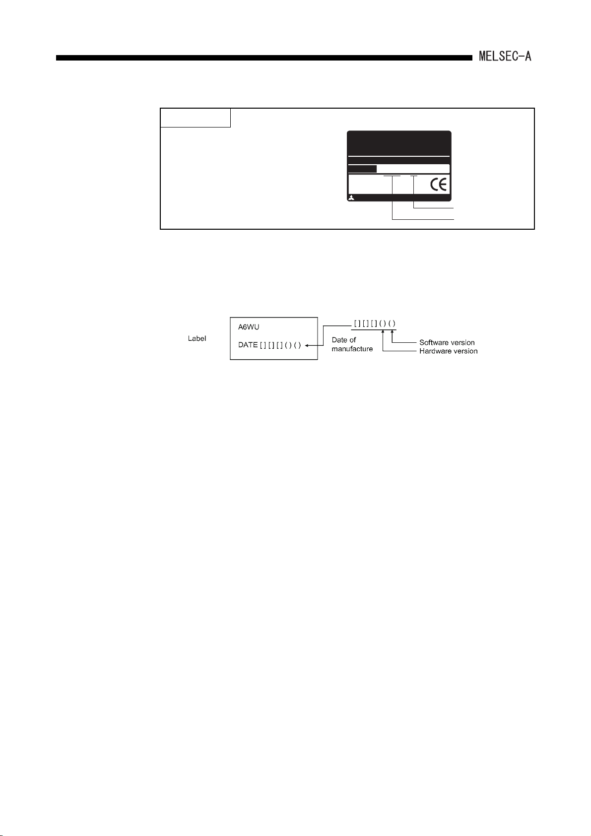
module marked "9707 B" or later in
MITSUB ISHI
CPU UNIT
MODEL
A2USHCPU-S1
MAX 30kSTEP
DATE
9707 B
the DATE column of the rated plate.
MITSUBISHI ELECTRIC
BD992D008H38
Function version
Date of manufacture
(3) Peripheral device
(a) Precautions when using an A6WU P-ROM writer
1) When using an A1SHCPU
Use an A6WU P-ROM writer module whose software version is E or later.
(b) The A6WU P-ROM writer module cannot be installed with add-on system, which
is installed directly in the AnSHCPU.
Only hand-held system, which is installed using cables, is possible.
(c) Among the programming modules (A7PUS and A8PUE), only the A7PUS can be
installed with add-on system.
Other models (A8PUE) can be installed with hand-held system, which is
connected with cables.
2 - 7
SYSTEM CONFIGURATION2.
(4) EP-ROM memory cassette ROM partition
Partitioning the EP-ROM memory cassette with an A6GPP (SW4GP-GPPA)/A6WU
requires a memory write adapter (optional).
The following shows the valid combinations of memory cassette and memory write
adapter:
CPU Model
A1SHCPU A1SNMCA-8KP 32k bytes
A1SJHCPU(S8) A1SNMCA-8KP 32k bytes
(5) Program write during operation with E
(a) When an operation is executed using an E
Memory Cassette
Model Capacity
2
PROM
Memory Write Adapter Model
A6WA-28P
2
PROM, write during RUN is not
possible. If write during RUN is executed, the following messages are displayed
on the peripheral devices:
For SW3GP-GPPA: "PLC COMMUNICATIONS ERROR : ERROR
CODE = 19"
For SW0RX-GPPA: "PLC COMMUNICATIONS ERROR :ERROR
CODE = 19"
For A7PUS: "PLC NOT RESPOND"
(b) The writing of the program cannot be executed from the computer link module or
from a peripheral device connected to other stations on the MELSECNET.
Write programs from peripheral devices connected to the AnSHCPU's RS-422.
2 - 8
2. SYSTEM CONFIGURATION
2.2.2 Software package
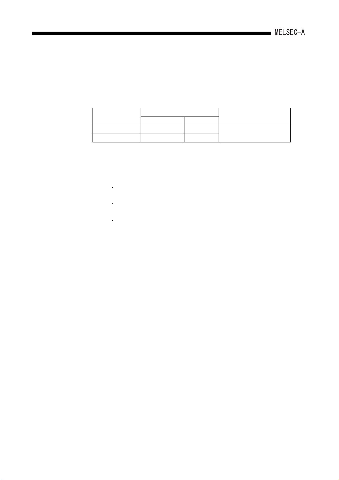
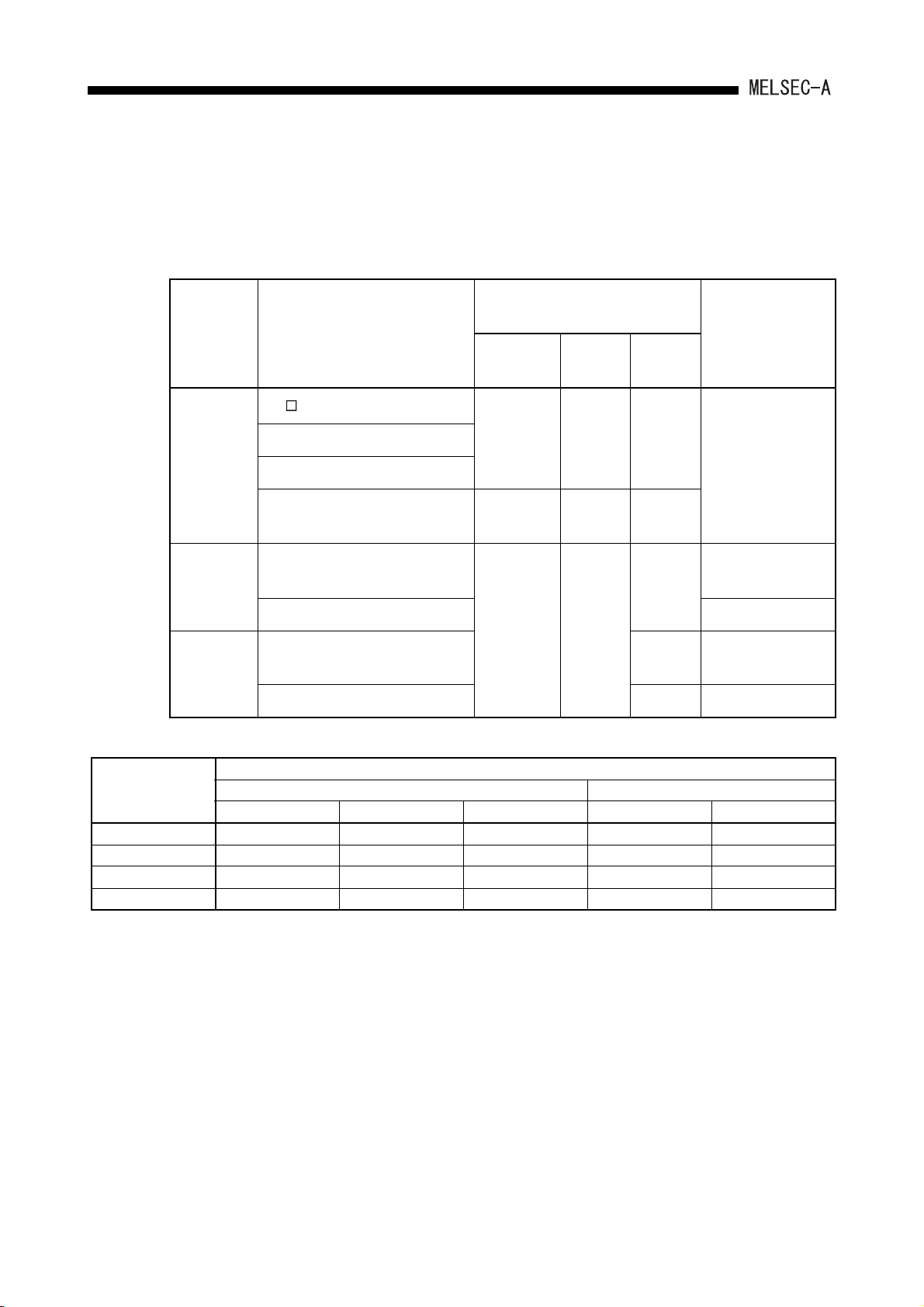
(1) GPP function software packages and model name setting at the start-up
(a) For AnSHCPU start-up, use the PLC model "A3".
(b) Perform the PLC type setting as shown below when using conventional
peripheral devices.
Peripheral
Device
Software Package for System
Start-u p
Programmable controller CPU
Model for Set-up
A1SJH
/A1SH
A2SH A2SH-S1
Remark
IBM PC/AT
SW IVD-GPPA
MELSEC MEDOC
*
A3
*
A3 A3
MELSEC MEDOC plus
A1SJH/
A1SH
A2SH A2SH-S1
A3
Writing on the ROM
is not allowed.
A6PHP
GX Developer
SW3GP-GPPA
SW4GP-GPPA
A3* A3
A6GPP SW3-GPPA
SW3GP-GPPA
A3
Writing on the ROM
is not allowed.
SW4GP-GPPA
*Select the model names according to the software package versions as shown below:
Model Name
Type
Select "A0J2H" Select "A1S" Select "A1SH" Select "A3" Select "A1SH"
SW4GP-GPPA Q or earlier R or later All versions
SW3RXV-GPPA 30D or earlier 40E or later 30D or earlier 40E or later
SW3NX-GPPA 60G or earlier 70H or later 60G or earlier 70H or later
SW3IVD-GPPA 60G or earlier 70H or later 60G or earlier 70H or later
For ROM Writing For Programming
2 - 9
 Loading...